A new software suite for separation concept evaluation...
20
Production Separation Systems, 6 th Annual Event IBC Conference, May 18-19 th , 1999 Stavanger, Norway A new software suite for separation concept evaluation and performance trouble-shooting John Ditria, Apex Process Technologies Inc. Abstract The oil and gas industry has undergone a significant change in the nature of its producing operations, and the recent low crude oil price environment has ensured this will continue. There is a consistent ongoing drive to reduce capital costs, improve the bottom line for existing operations, and to convert or shift marginal fields to clearly viable developments. To ensure this is achieved, problem solving needs to be innovative, with a new "mind-set" paradigm. Although significant effort has been placed on increasing production efficiencies, the majority of the high profile efforts have centered round drilling technologies. In comparison new production separation technologies, or the better understanding of conventional equipment performance has lagged behind. One of the reasons for this is the lack of consistent, widely used process separation tools applicable for process separation operations specifically found in the upstream oil and gas industry. This lack of consistent tools applies to many of the conventional separation equipment, and is certainly absent with the advent of newer separation equipment and technologies. It is widely accepted that cyclone based separation technologies are a key hardware element in returning flexible, smaller, more compact total production systems, with lower capital, maintenance, and operating costs. The applications for process separation studies and designs are numerous and increasing. These include traditional topsides equipment located downstream of the choke, separation equipment which may be located at the wellhead, and the special requirements for topsides process equipment operating in increasing water depths. Furthermore additional non-traditional locations are increasing and include the little understood downhole and subsea separation applications. As the potential sites for process separation increase, so does the potential for significant capital and operating cost reductions, however the complexity of the resultant process design "mix" also increases. A suite of cyclone simulation models for solid-liquid, liquid-liquid, and gas-liquid separation are presented together with a three phase separator providing a valuable tool for optimizing existing operations, and helping design better ones for the future. This is especially important where the number of separation sites increase, and become an integral part of future strategic production operations. Introduction In the last 5 to 10 years the widespread availability of computer based engineering hardware and software has significantly changed the way in which engineering professionals undertake their work. Advances in hardware technology, client-server based systems, and the use of the "Microsoft" standard, has placed enormous power at the hands of the professional, which only a few years ago was the sole province of company IT departments. Notwithstanding this current ability, maximum efficiency potential is far from realized for the process engineer in the oil and gas industry.
Transcript of A new software suite for separation concept evaluation...

Production Separation Systems, 6th Annual Event IBC Conference, May 18-19th, 1999 Stavanger, Norway A new software suite for separation concept evaluation and performance trouble-shooting John Ditria, Apex Process Technologies Inc. Abstract The oil and gas industry has undergone a significant change in the nature of its producing operations, and the recent low crude oil price environment has ensured this will continue. There is a consistent ongoing drive to reduce capital costs, improve the bottom line for existing operations, and to convert or shift marginal fields to clearly viable developments. To ensure this is achieved, problem solving needs to be innovative, with a new "mind-set" paradigm. Although significant effort has been placed on increasing production efficiencies, the majority of the high profile efforts have centered round drilling technologies. In comparison new production separation technologies, or the better understanding of conventional equipment performance has lagged behind. One of the reasons for this is the lack of consistent, widely used process separation tools applicable for process separation operations specifically found in the upstream oil and gas industry. This lack of consistent tools applies to many of the conventional separation equipment, and is certainly absent with the advent of newer separation equipment and technologies. It is widely accepted that cyclone based separation technologies are a key hardware element in returning flexible, smaller, more compact total production systems, with lower capital, maintenance, and operating costs. The applications for process separation studies and designs are numerous and increasing. These include traditional topsides equipment located downstream of the choke, separation equipment which may be located at the wellhead, and the special requirements for topsides process equipment operating in increasing water depths. Furthermore additional non-traditional locations are increasing and include the little understood downhole and subsea separation applications. As the potential sites for process separation increase, so does the potential for significant capital and operating cost reductions, however the complexity of the resultant process design "mix" also increases. A suite of cyclone simulation models for solid-liquid, liquid-liquid, and gas-liquid separation are presented together with a three phase separator providing a valuable tool for optimizing existing operations, and helping design better ones for the future. This is especially important where the number of separation sites increase, and become an integral part of future strategic production operations. Introduction In the last 5 to 10 years the widespread availability of computer based engineering hardware and software has significantly changed the way in which engineering professionals undertake their work. Advances in hardware technology, client-server based systems, and the use of the "Microsoft" standard, has placed enormous power at the hands of the professional, which only a few years ago was the sole province of company IT departments. Notwithstanding this current ability, maximum efficiency potential is far from realized for the process engineer in the oil and gas industry.

Work Processes When considering the exploitation of an oil and gas resource, the greatest potential in reducing capital and operating costs is in the Conceptual Design Phase where the process and basic engineering specifications are defined. During this stage over 75% of total capital requirements are identified, and over 30-40% of capital costs savings are possible. This is a critical, make or break stage in the development of any project, and as such one would expect that the full force of our technological ability would be utilized to integrate the process engineering work with the rest of the work. The traditional approach however still predominates today. This includes the one way flow of work between separate teams, with formal boundaries. Reservoir, process, mechanical, structural, and electrical/instrumentation engineers, amongst other, labor away with little time, let alone ability to care about the significant assumptions and therefore courses of action other disparate groups have on their recommended design discipline, and the resultant impact on the bottom line. Seamless, two-way, ongoing, iterative interaction is required, if we are to provide truly innovative solutions which are efficient, safe, cost effective and environmentally sound. It's essential that companies share up-to-date information through extensive network systems with cross-functional boundaries. It's hard to understand why first hand knowledge and models of actual operating plant, and their relevant designs (good and bad) are not used in every new project, or utilized for plant upgrades or improvements. IT The process engineer has some way to go to utilize the full potential of IT. Yes there are many tools available today, which cover operating systems (Windows98/NT, Unix), applications (AutoCAD, word processing, spreadsheets), various reservoir and pipeline simulation programs, and process simulation (Aspen, Hysys) packages to name a few. There are many fields of endeavor for the process engineer where little information exists, or principles are simply poorly understood, and the basic process unit operations in the upstream oil and gas industry are amongst them. Furthermore how many of the existing tools or models are linked/integrated from the 'coal face', i.e. starting at the reservoir, and end (for the upstream industry) at the refinery or petrochemical gate. To address this latter problem there has been an attempt to facilitate increasingly open systems and standards, to enable applications from different sources or suppliers to work together without users having to purchase or develop special interfaces for each product. There are two main ongoing initiatives to develop open process engineering standards, pdXi, and Cape-Open. Although these initiatives are a step in the right direction, they are well overdue, without obvious sight of a functional and complete operational conclusion that a majority of smaller software vendors can use. In the meantime numerous work areas need further investigation and automation. Summits' objective is to fill a very real void in the tools available to the process engineer, and begin to address the basic process unit operations in the upstream oil and gas industry. Features Summit is the culmination of over ten year's work in the cyclone based process separation equipment business. Significant field data gathered in the formative years of technology development between 1988 and 1994, together with an extensive literature search providing a source of approximately 600 technical papers and approximately 200 patents. Ongoing industry support is also provided from various individuals from oil and gas operating companies, and equipment manufacturers. These relationships will ensure a complete and comprehensive development, while guaranteeing the relevant needs of future users. This

contrasts the usual situation, where engineering companies seek assistance from third-party software vendors who are contracted to write engineering software. Most of the time these third-party software vendors do not have the in-house engineering expertise or the participation and focus of the potential end users Summit is an engineering environment that allows a multitude of Engineering Simulation/Application suites to reside within. Summit is designed to run on the Microsoft Windows 32 bit platforms (WinNT/Win95/Win98) and connect into a number of disparate information systems on the backend. Summit is an all-inclusive place to hold a myriad of engineering applications, custom or industry standard. The “Process Separation” Application Suite (or module) is the first engineering suite to be developed under Summit. The Process Separation module is used to advise and make recommendations for customer specific production separation equipment used in the upstream oil and gas industry. This module will solve the problems of high engineering costs, and often-inaccurate decisions at the vital conceptual engineering phase of a project. The Summit Engineering Environment uses state-of-the-art technologies to allow for maximum performance, flexibility and engineering capabilities. These technologies allow Summit to provide full engineering enterprise-level functionality. Some of the technologies in use are: Full 32 bit Windows application client interface Implementation of 32 bit Windows application graphical user interface based application. This design is optimized for Microsoft Windows platforms by running at the fastest possible speed with the utmost stability. Emphasis is placed on running effectively on the Windows NT/95/98 desktop and server platforms. These platforms have continued to set the standard in usability and functionality and are the primary choice for graphic user interface (GUI) development. Regardless of back-ends, full functionality will continue to be provided for the Windows desktop front-end. Microsoft Component Object Model Architecture (COM) The underlying object architecture of Summit is written in Visual C++ using COM interfaces. These interfaces present an industry standard object-programming model for the Microsoft Windows platforms. Due to this level of abstraction, complex engineering simulations are broken into simpler components with code re-use where appropriate. These object oriented methodologies present an environment that allows for much more software customization as well as debugging in a smaller amount of time. Microsoft Active Server Pages (ASP) COM Internet/Intranet Programming Model The ASP Internet programming model has created a COM compliant development environment that allows for quick and flexible HTML programming. All COM components developed for the Summit Engineering Environment are available for use via the ASP interfaces. These components will also allow themselves to be integrated into the Microsoft Transaction Server to allow for greater Server-Side stability and performance. These capabilities allow for quick delivery of the Summit simulations to the Web. This delivery will include lease options for instantaneous delivery of simulation capabilities over the Web or the ability to setup an in-house Intranet server for simulation delivery within an individual corporate network. Heterogeneous Development Environments A ‘best of breed’ methodologies has been chosen for determining which development environments are to be used for which portions of the Summit development. There has been considerable design work undertaken to this end to allow for maximum flexibility and performance under minimum development times. The user interface has been programmed in Visual Basic and will call COM components that are developed in Visual C++. The decision to use Visual Basic in the GUI portion of the initial application was due to the flexibility and speed of delivery of Visual Basic developed user interfaces. The use of Visual C++ in delivery of the COM components is based entirely upon speed of calculations and scalability of the application. ASP will continue to provide our Web interface capabilities. We believe that the successful mix of these three development environments in each circumstance brings out the best capabilities of each of the

environments. Visual Basic allows for a flexible GUI, Visual C++ provides stable and quick calculation components while ASP delivers HTML functionality. Design Basis Summit provides a steady state simulation model for six specific unit operations, along with a Fluid Properties Calculator, and a design structure to facilitate future basic process flow diagram (PFD) ability. The overall philosophy for user involvement (input/output) is “minimum in – maximum out”.
Fluid Properties Satisfactory modeling of any unit operation requires accurate input characteristics of the process fluids. The initial version of this software will utilize a “minimum in” approach, where only a small number of fluid characteristics are required as inputs. These include temperature and pressure at process conditions, and flowrate, specific gravity, and (dispersed) particle size of the four main constituents, oil, gas, water, and solids. From this information the model generates a complete range of fluids properties required to run the simulations. Utilizing industry proven fluid properties correlation's', a complete range of accurate fluid properties (density, viscosity, surface tension, mixture density, etc.) can be generated. Furthermore an override facility allows for the manual input of variables where the user has better information. The simulation models are very much "particle size" driven, and it is recognized that this variable is very difficult to predict and measure accurately. However the model is designed to allow for easy "what-if" analysis on this and other inputs, returning design impacts over a wide range of scenarios. This powerful functionality addresses an aspect of design frequently overlooked.
Model Operations The initial choice of unit operations was based on providing information which had the potential to provide the largest impact on the operation of existing process separation train designs, and by providing information on equipment which has been the most difficult to find to date. Each unit operation module is made up of four main sections, designed to reflect the work requirements of a process engineer. The main sections include: Specify Process: Here an engineer is investigating a new concept or project, knows what specification is required and needs to know the applicability of the equipment to do the job, how well the specification is meet, how sensitive to changing fluid conditions, and how many equipment items required. Specify Model: Here an engineer is investigating the performance of an existing product or equipment in the field, and wants to check/verify performance under changing fluid conditions. This is a particularly powerful diagnostic tool, where field data can used to accurately reflect the performance of the equipment. Results: Performance information via graphs and/or tables is provided showing a complete analysis of the case study. Tabular information is provided in a material balance format so that the separation characteristic of each component can be followed. Mechanical: The number of units required, to allow for preliminary specific equipment drawings and layout designs. Future versions will include equipment size and weight details.
Unit Operations Solid-Liquid Separation Desander and Multiphase Desander models have been built around field proven correlations and mechanistic principles to generate performance and efficiency correlation's, hydraulic

(flowrate) relationships, and equipment sizing criteria. Desanding is the separation of produced sand from crude and/or water, and the Multiphase Desander is the same however can deal with various amounts of free gas. In all cases, the discussion will be based on static hydrocyclones. Lynch-Rao or Plitt models, is the basis of the calculations, with additional models including Lieth/Licht, and Stairmand providing information for high gas void fraction (GVF) cases. Recovery curves and particle size distributions are provided for comparison of various scenarios. Input particle size distribution is predicted with a two-parameter log-probability function. Mechanistic sizing are produced as output, and provides the best technology available from existing manufactures. A simple Expert System is included to check and ensure that the models are operating within the appropriate operating envelope for this equipment. Solid liquid cyclones are a very old, well know technology, and there are literally dozens of manufacturers with suitable products for the oil and gas industry. Liquid-Liquid Separation Deoiler and Dewaterer models have been built around field proven correlation's and mechanistic principles to generate performance and efficiency correlation's, hydraulic (flowrate) relationships, and equipment sizing criteria. Deoiling is the removal of residual oil from produced water, and Dewaterering is the dehydration, or liquid-liquid separation of water from crude. Performance prediction includes the use of Lynch-Rao models, together with substantial field data. Flow split, pressure ratio, and water cut performance/relationships have been modeled to encompass the range of applications experienced in the field. Input particle size distribution is predicted with a two-parameter log-probability function. A simple Expert System is included to check and ensure that the models are operating within the appropriate operating envelope for this equipment. Mechanistic sizing are produced for output, and reflect the best technology available from existing manufactures. Liquid liquid cyclones first appeared in the oil and gas industry in the early 1980's, and have since flourished as a basic component of any process train. As such there are over a dozen manufacturers, with suitable product offerings for the oil and gas industry. Gas-Liquid Separation An Axial Flow Cyclone provides bulk gas-liquid separation. A model has been built around field proven correlation's and mechanistic principles to generate pressure drop versus throughput relationships, gas carryunder, liquid carryover, and equipment sizing. Simplistic slug handling algorithms have been modeled to handle certain non-steady conditions. A simple Expert System is included to check and ensure that the models are operating within the appropriate operating envelope for this equipment. Gas-Liquid-Liquid Separation A Three Phase Separator model has been built to provide a solid base framework for some of the current modeling scenarios for this equipment. This model has been built around field proven correlation’s based on Stokes Law, and published mechanistic principles to generate inlet momentum versus shear relationships (gas and liquid shear), gas carryunder, liquid carryover, liquid-liquid separation, sand separation and filling, and equipment sizing. The model is segmented into seven main areas, made up of one inlet or staging zone, which reflects the impact of baffle plates or other (cyclone) inlet device, and six separation zones which individually or collectively determine the criteria for the sizing of the separator. These include the bulk gas, gas-liquid separation (demister), bulk crude, oil/gas emulsion, bulk water, oil/water emulsion zones. There are numerous manufacturers of three phase separators, and even though all have their design "enhancements", they all follow the same laws of physics which have their fundamental basis modeled in Summit. Options for internals, such as baffles, inlet devices (cyclones, momentum plate, cascades, etc.), coalescence plates, vane packs, mist pads, sand jetting, weirs, and buckets can all be additionally modeled simply within the architecture provided.

Case Study The simulations models provided can be utilized for topsides, subsea, and downhole process separation applications. To illustrate the use of Summit we have provided an example, which reflects the use of most of the unit operations provided, investigating a process environment which is not typical or well understood - Subsea Separation. Figure 1 shows a PFD for a patented design of a complete subsea separation system (U.S. Patent Pending Application No. 09/250,584, Subsea Multiphase Fluid Separating System and Method). The objective here is for a Deepwater Production Separation System, to separate subsea in one integrated unit, the four (4) main constituents of hydrocarbons production; oil, gas, water, and solids. The system will be designed to operate in any water depths, however the significantly reduced size and weight of the system, compared to existing technology, lends itself to much greater water depths (over 5,000ft). If the specification by an end user is for the separation of only two or three constituents of hydrocarbon production, this can be handled seamlessly as well. It is beyond the scope of this paper to detail issues concerning subsea separation, however the following briefly shows how Summit can help us evaluate the potential of this technology in a strategically important area. Figure 2 shows the Summit input page for one of the design criteria from the recent CoSWaSS Joint Industry Program (JIP). The JIP's objective was to identify a subsea separation process, and this public domain information will serve as the basis of our input stream. Figures 3 to 4 show some of the program-generated information, which are required as input to the unit operations. A manual override is possible for each variable where the user has better information. Figures 5 to 9 show the unit operations for the multiphase desander, axial flow gas liquid cyclone, dewaterer, three phase separator and deoiler simulations respectively. Simulations are simple, intuitive, and easy to use. Output information is provided via graphs and material balance type tables. Also provided are equipment numbers and sizes to facilitate P&ID's, equipment layouts and skid arrangements. Figure 10 shows the detailed PFD resulting from the simulations, together with design, sizing, and summary material balance information. Figure 11 provides a 3-D rendition of the final design. A separate "what-if" case was undertaken, simulating a conventional (separator only) design. Figure 12 show the result of this conventional approach, verses the innovative cyclone-based approach. The cyclone-based system is 15-20% of the weight of the single separator, and the individual retrievable cyclone components are 3-5% of the size and weight of the single separator. As can be seen in this case, in increasingly deeper water depths, the use of a three-phase separator is simply not feasible due to the significant size and weight of such a system, especially during mobilization/demobilization and retrieving periods. Future Developments Summit is a 'work in progress' initiative, and substantial ongoing work is proceeding. The basis for any future work however will involve industry support and involvement. This provides the credible foundation required for widespread acceptance. To date this has been positive, and a number of oil and gas companies have voiced their commitment to be part of a formal steering committee to help further direct Summit's development. Some of these future developments may include: Medium Term (1-2 Years) The medium term goal is to provide an application with an open-system framework as a focal point for the accumulation of data and its transformation into useful information. • A software suite that provides most of the unit operations for the upstream oil and gas
industry (electrostatic coalescers, flotation equipment, centrifuges, filtration units,

chokes/valves, biofouling and other chemical units, etc.). These can be supplemented with modules (in particular gas handling unit operations) from other programs like HYSYS.
• PFD to allow simple integration of the unique unit operations provided. Summit will embrace other product offering functionality (i.e. PFD) on request from a customer, or when the open standards are ready to allow easy interface integration.
• Inclusion of transient and/or dynamic modeling capabilities to more closely match real life production
• Enhancement of the Fluids Properties Calculator to include full component breakdown and specification from established thermodynamic tables. This will only be necessary when the performance models can use this additional information.
• Addition of a separate economic evaluation module for conceptual case studies evaluations • Capability for inclusion of customer specific engineering software solutions. • Software functionality automation-enabled to allow other packages/applications including
Microsoft Office/AutoCad to remotely initiate Summit capabilities. • Available and delivered through the internet or customer-private intranet Long Term (3+ years) The long-term goal for the application is only limited by the information technology available. • an industry standard software suite that provides process simulation for all upstream oil and
gas unit operations • integrates complete process equipment design with economic evaluation of various case
studies • utilized for conceptual designs, to detailed design, and seamless integration into AutoCAD
and other skill specific packages. • Utilized for "real-time" trouble shooting in the field through a diagnostic ability (expert
system) that can take field information locally and disseminate globally either back to a home office environment, or to experts in disparate locations.
• Data Warehoused and Real Time information acquisition and analysis to enable immediate fully remote management and process control from any point in the world.
Conclusions Apex Process Technologies has developed the Summit Engineering Environment into the type of tool that will be the one all-inclusive environment for solving tough engineering problems specifically for the upstream oil and gas industry. Over time, Summit will evolve to meet all process engineering requirements whether they be small systems simulation, or large real-time data analysis. Customer participation with this product will lead to a significant development and improvement in the manner in which process engineers undertake production separation work in our industry. It will also move the client a little closer to the technological advancements made by other areas in the industry (drilling), and shift the total production “bottleneck” which seems so often to be defined by, and reside with, the separation equipment.

Bibliography BRADLEY H. B., et al, "Petroleum Engineering Handbook, 3rd Edition," Society of Petroleum Engineers, 1992. McCAIN, W.D. Jr., “The Properties of Petroleum Fluids, 2nd Edition,” Penwell Publishing Company, 1990. MOCK T., MOCK B., and BRITT H., "Integrate Work Processes to Cut Plant Life-Cycle Costs", Chemical Engineering, October 1998 References eProcess Technologies Inc., Summit Engineering Environment Manual, May 3rd, 1999 Applied Petroleum Services Pty. Ltd. Database. “Interactive Data Plotting – User’s Manual,” Fine Particle Software, 1989.
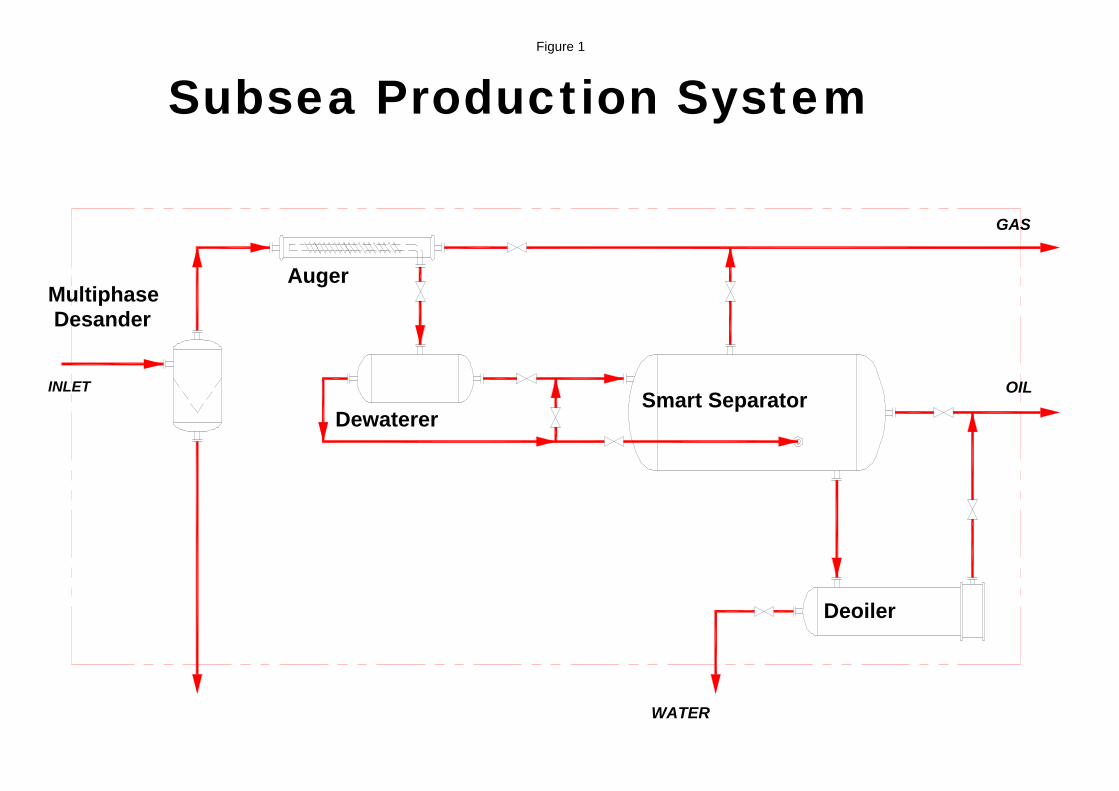
Figure 1
Subsea Production System
Multiphase Desander
Auger
Dewaterer Smart Separator
Deoiler
INLET OIL
GAS
WATER

Figure 2

Figure 5

Figure 6

Figure 7
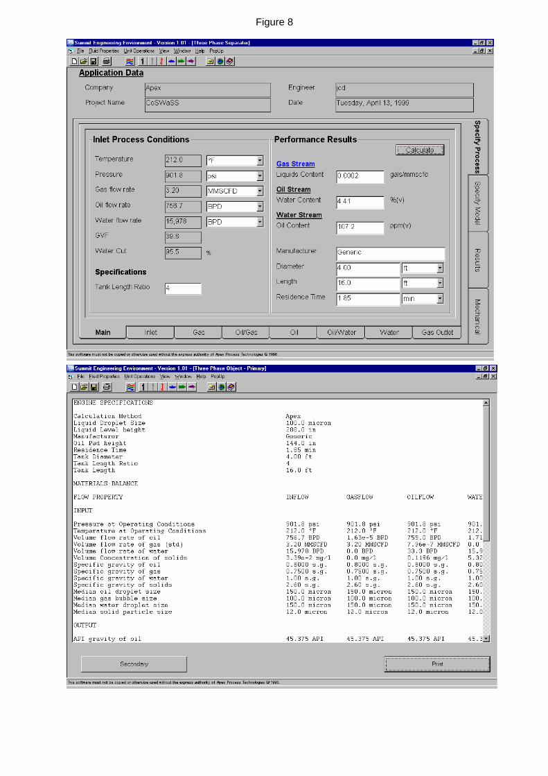
Figure 8

Figure 9

Figure 10
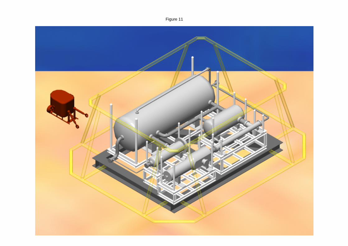
Figure 11

Figure 12

Figure 3

Figure 4