A New Simulator to Recreate Extr eme Dynamic Loads on ... · Category 5 wind loads on full-scale...
9
The 2012 World Congress on Advances in Civil, Environmental, and Materials Research (ACEM’ 12) Seoul, Korea, August 26-30, 2012 A New Simulator to Recreate Extreme Dynamic Loads on Large-Scale Building Component and Cladding Systems *S. Y. Shen 1) , F.J. Masters 2) and H. Upjohn II 3) 1),2) Dept. of Civil and Coastal Engineering, Univ. of Florida, Gainesville, FL, U.S.A 3) Special-Lite, Inc. Decatur, MI, U.S.A 1) [email protected] ABSTRACT A new large-scale hurricane simulator is under construction in the Powell Family Structures and Materials Laboratory at the University of Florida. This facility is designed as a method to replicate naturally occurring wind and pressure in a controlled laboratory environment. The simulator was designed to reproduce Saffir-Simpson Hurricane Scale Category 5 wind loads on full-scale building components and cladding systems with a maximum plan area of 40 m 2 . The simulator was designed to recreate an entire hurricane passage (>12 hours) at up to a 22 kPa pressure. The facility should be able to test specimens that exhibit large air leakage (< 47 m 3 /s) and deflections (< 1 m) under replicated wind loads. The paper provides an update on the development of the facility, which will be operational in summer 2012. Details about the final configuration, validation and initial experiments will be discussed during the conference session. Keywords: large-scale; hurricane simulator; pressure loading actuator 1. INTRODUCTION Hurricanes cause approximately $10 billion in damage in the continental United States annually (Pielke 2008), and the damage continues increasing with the growing 1) Assistant Professor 2) Graduate Student 3) Chief Executive Officer
-
Upload
nguyennguyet -
Category
Documents
-
view
221 -
download
0
Transcript of A New Simulator to Recreate Extr eme Dynamic Loads on ... · Category 5 wind loads on full-scale...

The 2012 World Congress on Advances in Civil, Environmental, and Materials Research (ACEM’ 12)Seoul, Korea, August 26-30, 2012
A New Simulator to Recreate Extreme Dynamic Loads on Large-Scale Building Component and Cladding Systems
*S. Y. Shen1), F.J. Masters2) and H. Upjohn II3)
1),2)Dept. of Civil and Coastal Engineering, Univ. of Florida, Gainesville, FL, U.S.A
3)Special-Lite, Inc. Decatur, MI, U.S.A
ABSTRACT
A new large-scale hurricane simulator is under construction in the Powell Family Structures and Materials Laboratory at the University of Florida. This facility is designed as a method to replicate naturally occurring wind and pressure in a controlled laboratory environment. The simulator was designed to reproduce Saffir-Simpson Hurricane Scale Category 5 wind loads on full-scale building components and cladding systems with a maximum plan area of 40 m2. The simulator was designed to recreate an entire hurricane passage (>12 hours) at up to a 22 kPa pressure. The facility should be able to test specimens that exhibit large air leakage (< 47 m3/s) and deflections (< 1 m) under replicated wind loads. The paper provides an update on the development of the facility, which will be operational in summer 2012. Details about the final configuration, validation and initial experiments will be discussed during the conference session. Keywords: large-scale; hurricane simulator; pressure loading actuator
1. INTRODUCTION
Hurricanes cause approximately $10 billion in damage in the continental United States annually (Pielke 2008), and the damage continues increasing with the growing
1) Assistant Professor 2) Graduate Student 3) Chief Executive Officer

population and properties in the coastal areas which are highly vulnerable to hurricanes. Wind-induced losses are primarily attributed to damage of buildings. For example, in August of 1992, Hurricane Andrew struck the northwestern Bahamas, southern Florida and southwest Louisiana and caused approximately $45 billion in damage, and 70% of the damage was caused as a result of the breach of the building envelope on low-rise buildings (O'Brien 1995). During hurricane Andrew, more than 25,000 homes were destroyed and more than 100,000 others were damaged in southern Dade County, Florida (Ed Rappaport 1993). Therefore, improving wind-resistance of low-rise buildings can significantly mitigate hurricane-induced losses.
Historically, wind-resistant design focused on the main wind load-resisting frame system (O'Brien 1995). However, hundreds of post-storm investigations have found that building envelope system is a significant contributor to damage (e.g., Minor 2005), particularly for infrastructure constructed under older building codes. Damage to the building envelope (e.g. the loss of panels of roof sheathing, the breakage of window glasses) can result in water ingress, sudden increases in internal pressure that overpressure the roof system, among other cascading factors that lead to severe damage.
This paper addresses recent efforts to develop large-scale testing apparatuses those are capable of recreating time-varying wind speed/load conditions at “full-scale,” i.e. simulating storm conditions at sufficient scale to evaluate the performance of full-size building systems. The authors have developed a dual-mode system capable of replicating both time-varying wind speed and pressure. This facility is scheduled to be commissioned in summer 2012.
2. EXISTING FULL-SCALE WIND FLOW/LOAD TESTING FACILITIES
This project was inspired by multiple wind engineering efforts directed at recreating
stochastic wind loads on building systems. The first notable project was the BRE Real-time Wind Uniform Load Follower (BRERWULF), which was developed by the Building Research Establishment (BRE) in the United Kingdom to investigate the performance of multi-layer cladding systems subjected to temporally fluctuating wind loads. The system utilized a closed-loop control system that varied pressure in a test chamber to follow a prescribed stochastic pressure sequence (Cook 1988). In the 2000s, the University of Western Ontario started the “Three Little Pigs” (3LP) project to develop the next generation BRERWULF system (Kopp 2010), which is called the Pressure Loading Actuator (PLA). Each PLA is able to recreate temporally fluctuating wind pressure, and spatial variations of wind pressure can be realized by using many PLAs simultaneously. The control valve system of this facility was designed to generate a linear relationship between produced pressure and valve position.

More recently, Florida International University (FIU) and the Insurance Institute for Business & Home Safety (IBHS) have developed full-scale boundary layer wind field simulators. Since 2003, FIU has been developing the Wall of Wind (WoW) in multiple stages (Chowdhury 2009). The FIU WoW facility has gone through from 2-fan, 6-fan to currently 12-fan phases, and the 12-fan WoW system is designed to produce sustained wind velocity in excess of 65 m/s to test full-scale structures. This facility, which is still in development, will use passive devices and active control mechanism to generate the desired wind flow characteristics (Bitsuamlak 2009). The Windstorm Test Facility developed in the IBHS Research Center is actually a full-scale wind tunnel. This facility has a large fan system comprised of 105 1.68 m (6 foot) diameter variable speed fans, and is capable of generating up to Category 3 hurricane wind conditions (Liu 2009). The test chamber of the full-scale wind tunnel has a large dimension of 44 m long × 44 m wide × 21 m high, enabling the facility to test one- or two-story structures with a cross-section area up to 220 m2. The proportional-integral-derivative technique employed in the control system is able to produce an approximately linear relationship between flow velocities and fan RPM.
3. THE LARGE-SCALE DYNAMIC WIND LOAD SIMULATOR AT THE UNIVERSITY OF FLORIDA
In 2009, the authors began development of a new large-scale dynamic wind load
simulator (henceforth Simulator) to recreate extreme wind and wind loads to test large/full-scale building components and cladding systems. Goals of the project are to:
1) Recreate time-varying wind and wind loads representing Category 5 Hurricane winds in a controllable laboratory environment;
2) Investigate hurricane-induced behaviors of building systems, and thus contribute for future retrofitting, optimization, design, building code modification, etc.;
3) Validate and enhance the numerical simulation of structures, which is cost- and time-efficient.
The Simulator has four main components: a fan system, ducting, a control system
and a test chamber (Fig. 1). A centrifugal fan, driven by a Caterpillar 3512 DITA diesel prime mover, produces the required pressure and air flow rate. The fan is able to generate pressures in the range of 23 kPa (90 in. wg), and a flow rate of 47 m3/s. The ducts connecting the fan and the air-box are made of 9.5 mm (3/8 in) thick steel. The circular parts of the ducting have an internal diameter of 1524 mm (60 in). In addition, two VAW duct silencers are incorporated in the inlet and outlet of the ducting system respectively to isolate the possibly resultant noise from the operation of the Simulator. The control system is comprised of four butterfly dampers and one opposed blade damper, which work together to recreate target wind pressure/velocity traces.

Fig
Theconcrehigh × 3/8 is cfull-scapressuthe effea potenbuilding
4. CO
Thedampe
ure 1. Thr
e pressureete and a r
0.9 m deeconnected ale buildinre in a coects of rainntial methog product a
ONTROL SY
e control sers and a c
ree-dimens
e test chareaction fraep (24 ft × to the air-
g systemsntrollable n to structuod to replaapproval te
YSTEM
system of custom-bui
sional draw
mber is came made
18 ft × 3 -box througs to be telaboratory ures can beace or redests adapte
the Simullt fast-actin
wing of the
comprised of steel. Ift), and thegh the posested undenvironme
e investigaduce the need from AS
lator is cong oppose
Simulator
of a test It has dimee reaction st-tensioniner replicatent. By adated as weeed for simSTM proce
omprised oed blade da
with the m
chamberensions of frame ma
ng bars. Thted hurrica
dding windell. This fullmple diagnedures.
of five damamper loca
major comp
made of f 7.3 m widade of HSShe simulatoane wind -driven rail-scale facinostic tools
mpers: fouated upstre
ponents
reinforcedde × 5.5 mS16 × 12 ×or enablesand wind
in devicesility can bes, such as
ur butterflyeam of the
d m × s d , e s
y e
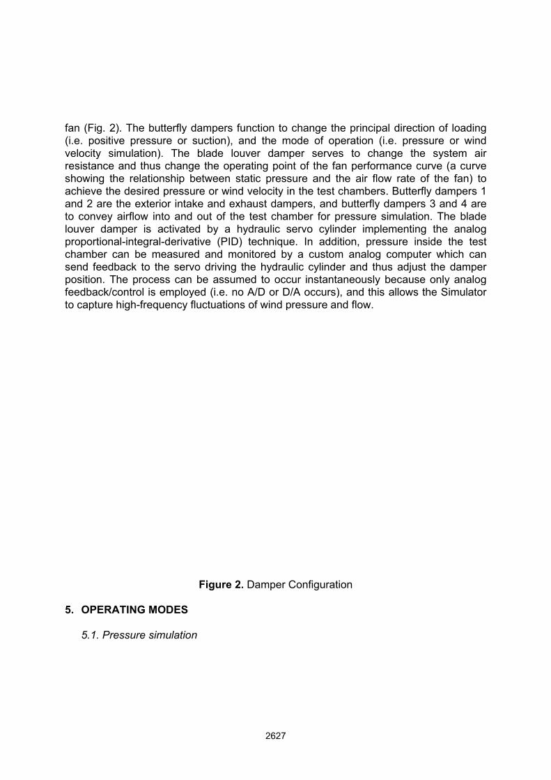
fan (Fig(i.e. povelocityresistashowinachieveand 2 to convlouver proportchambsend fepositionfeedbato capt
5. OP
5.1.
g. 2). The ositive prey simulationce and th
ng the relae the desirare the exvey airflowdamper i
tional-integber can beeedback ton. The pro
ack/control ture high-fr
ERATING
. Pressure
butterfly dssure or son). The hus changationship bred pressu
xterior intakw into and s activategral-derivae measureo the servocess can is employ
requency f
MODES
simulation
dampers fusuction), ablade loue the oper
between sture or windke and exhout of the
ed by a htive (PID)d and mo
vo driving tbe assum
yed (i.e. nofluctuations
Figure 2.
n
unction to and the muver damprating pointatic press
d velocity inhaust dame test chamydraulic s technique
onitored bythe hydrau
med to occo A/D or D/s of wind p
. Damper C
change thode of opper servesnt of the fasure and tn the test c
mpers, and mber for pservo cyline. In addiy a customulic cylindecur instanta/A occurs)
pressure an
Configurati
he principaperation (i.s to chan
an performhe air flowchambers.butterfly d
pressure sinder impletion, press
m analog cer and thuaneously b), and this nd flow.
ion
l direction e. pressurnge the s
mance curvw rate of t. Butterfly ddampers 3 imulation.
ementing tsure insidcomputer s adjust thbecause oallows the
of loadingre or windsystem airve (a curvethe fan) todampers 1and 4 areThe bladehe analoge the testwhich canhe dampernly analog
e Simulator
g d r e o 1 e e g t
n r g r

Test specimens are mounted into the reaction frame at the mouth of the pressure chamber. Opening butterfly dampers 3 and 4 allows air flow to enter into and run out of the chamber and thus change the internal pressure. As mentioned above, the rate of air supply is regulated by the blade louver damper. Closing the louver damper will increase the resistance of the system and thus results in the fan to produce higher static pressure and less airflow, and vice versa. Therefore, changing the inclined angle of the blades changes the pressure applied on test specimens. With the incorporation of the feedback signal from measuring the pressure inside the test chamber, a desired pressure trace is able to be achieved by adjusting the position of the louver damper. Pressure data will be acquired from wind tunnel modeling records. This research focuses on low-rise buildings, which are common for commercial, residential and industrial use (St. Pierre 2005). The US National Institute of Standard and Technology (NIST) has created an aerodynamic database of wind-induced pressure time histories on the envelope of various low-rise buildings (Chen 2003), and was chosen in this research for the pressure simulation. For example, a pressure time history with 10 Hz frequency and -14 kPa peak pressure shown in Fig. 3 can be possibly replicated by the Simulator. The pressure sequence was extracted from wind tunnel data measured at University of Western Ontario (UWO)
The fan and control system enable the Simulator to produce a maximum pressure of 23 kPa and a maximum pressure change of 10 Hz. Additionally, the fan is capable of
testing building components and cladding systems with high flow leakage up to 47 m3/s, and the size of the air-box allows the specimen to deflect up to 1 m during pressure simulation.
Figure 3. An example of pressure time history from wind-tunnel data measured at the University of Western Ontario
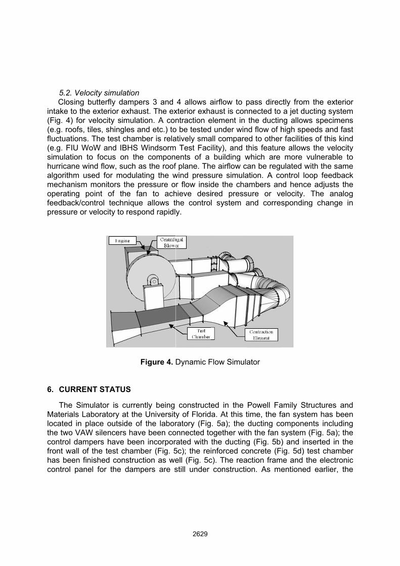
5.2. Closintake (Fig. 4(e.g. rofluctua(e.g. Fsimulathurricaalgorithmechaoperatifeedbapressu
6. CU
TheMaterialocatedthe twocontrolfront whas becontrol
. Velocity ssing butteto the exte) for veloc
oofs, tiles, tions. The IU WoW ation to foc
ane wind flohm used fanism moning point
ack/control re or veloc
RRENT ST
e Simulatoals Laborad in place o VAW sile dampers
wall of the een finishe panel for
simulation rfly dampeerior exhaucity simulatshingles atest cham
and IBHS cus on theow, such afor modulaitors the pof the fatechnique
city to resp
TATUS
or is currenatory at the
outside ofencers hav
have beetest chamd construcr the damp
ers 3 and ust. The extion. A con
and etc.) tomber is rela
Windsorme componas the roofating the wpressure oan to ache allows tpond rapidl
Figure 4.
ntly being e Universityf the labor
ve been con incorporber (Fig. 5ction as wepers are s
4 allows axterior exhantraction e
o be testedatively sma Test Facents of a f plane. Thwind pressr flow insid
hieve desihe controly.
Dynamic F
constructey of Floridratory (Fig
onnected torated with 5c); the reiell (Fig. 5cstill under
airflow to aust is con
element in under win
all compareility), and tbuilding w
e airflow cure simulade the chaired pressl system a
Flow Simul
ed in the a. At this t. 5a); the
ogether witthe ductininforced coc). The rea
constructi
pass direcnnected to
the ductinnd flow of hed to otherthis featurewhich are can be reguation. A coambers ansure or veand corres
ator
Powell Fatime, the fducting co
th the fan sg (Fig. 5b)oncrete (Faction framion. As me
ctly from tha jet ducti
ng allows shigh speedr facilities oe allows thmore vul
ulated withontrol loopnd hence aelocity. Thsponding
amily Strucfan systemomponentssystem (Fi) and inseig. 5d) tes
me and theentioned e
he exterioring systemspecimensds and fastof this kindhe velocitynerable to
h the samep feedbackadjusts thehe analogchange in
ctures andm has beens includingig. 5a); therted in the
st chamber electronic
earlier, the
r m s t d y o e k e g n
d n g e e r c e
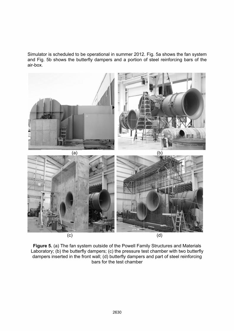
Simulaand Figair-box
FiguLabodam
ator is scheg. 5b show
x.
ure 5. (a) Tratory; (b) pers insert
eduled to bws the but
(a)
(c)
The fan systhe butterfted in the f
be operatiotterfly dam
stem outsidfly damperfront wall; (
bars f
onal in summpers and
de of the Prs; (c) the p(d) butterflfor the test
mmer 2012a portion o
Powell Fampressure tey damperst chamber
. Fig. 5a sof steel re
(b)
(d)
mily Structuest chambes and part o
hows the feinforcing b
ures and Mer with twoof steel rei
fan systembars of the
Materials o butterfly inforcing
m e
ACKNOWLEDGEMENTS
The authors appreciate Special-Lite Inc. for providing primary financial and technical support. We are also grateful to the Florida Building Commission and the Florida State University Florida Catastrophic Storm Risk Management Center for providing financial support for construction of the equipment. The authors would also like to thank the students and staff at the Powell Family Structures and Materials Laboratory at the University of Florida for the construction of the system.
REFERENCES Bitsuamlak, G. T., Chowdhury, A. G. and Sambare, D. (2009). “Application of a full-scale testing facility for assessing wind-driven-rain intrusion.” Building and Environment, 44(12), 2430-2441. Chen, Y., Kopp, G. A. and Surry, D. (2003). “Interpolation of pressure time series in an aerodynamic database for low buildings.” Journal of Wind Engineering and Industrial Aerodynamics, 91(6), 737-765. Chowdhury, A. G., Simu, E. and Leatherman, S. P. (2009). “Destructive Testing under Simulated Hurricane Effects to Promote Hazard Mitigation.” Natural Hazards Review, 10(1), 1-10. Cook, N. J., Keevil, A. P. and Stobart, R. K. (1988). “BRERWULF - The Big Bad Wolf.” Journal of Wind Engineering and Industrial Aerodynamics, 29, 99-107. Edward Rappaport, (1993). “Hurricane Andrew Preliminary Report.” National Hurricane Center. Kopp, G. A., Morrison, M. J., Gavanski, E., Henderson, D. J. and Hong, H. P. (2010). “‘Three Little Pigs’ Project: Hurricane Risk Mitigation by Integrated Wind Tunnel and Full-Scale Laboratory Tests.” Natural Hazards Review, 11(4), 151-162. Liu, Z., Smith, J., Masters, F. and Reinhold, T. (2009). “Assessment of Wind Storm Facility at the Insurance Center for Building Safety Research.” The seventh Asia-Pacific Conference on Wind Engineering, Taipei, Taiwan, 8 pages. Minor, J., (2005). “Lessons learned from failures of the building envelope in windstorms.” Journal of Architectural Engineering, 11(1), 10-13. O'Brien, C. C., (1995). “Full-Scale structural testing for severe wind, 1995.” The INEL Severe Windstorm Testing Workshop, 48 pages. Pielke, R., Gratz, J., Landsea, C., Collins, D., Saunders, M. and Musulin, R. (2008). “Normalized Hurricane Damage in the United States:1900-2005.” Natural Hazard Review, 9(1), 29-42. St. Pierre, L. M., Kopp, G. A., Surry, D. and Ho, T. C. E. (2005). “The UWO contribution to the NIST aerodynamic database for wind loads on low buildings: Part 2. Comparison of data with wind load provisions.” Journal of Wind Engineering and Industrial Aerodynamics, 93(1), 31-59.