A new family of field portable transmission test sets for ... · A new family of field portable...
29
A new family of field portable transmission test sets for applications to 10Gb/s J2126A J2127A SONET: OC-192, OC-48, OC-12, OC-3, OC-1, STS-3, STS-1 SDH: STM-64, STM-16, STM-4, STM-1, STM-0 T-carrier/PDH: DS1, DS3, 2Mb/s, 8Mb/s, 34Mb/s, 140Mb/s
Transcript of A new family of field portable transmission test sets for ... · A new family of field portable...

A new family of field portabletransmission test sets for
applications to 10Gb/s
SONET:OC-192, OC-48, OC-12, OC-3, OC-1, STS-3, STS-1
SDH:STM-64, STM-16, STM-4, STM-1, STM-0
T-carrier/PDH:DS1, DS3, 2Mb/s, 8Mb/s, 34Mb/s, 140Mb/s
J2126AJ2127A
1

Contents Introduction
Summary of capability .................................................................................................................................................... 3 Instrument tour................................................................................................................................................................ 4 SmartTest ........................................................................................................................................................................ 6 SignalWizard ................................................................................................................................................................... 6 SONET/SDH testing ........................................................................................................................................................ 7 DSn/PDH testing............................................................................................................................................................. 7 Additional measurements ............................................................................................................................................... 7
Technical specification
Interface specifications ................................................................................................................................................... 8 Test interfaces................................................................................................................................................................. 8 Optical transmitters ......................................................................................................................................................... 9 Optical receivers............................................................................................................................................................10 Electrical interfaces.......................................................................................................................................................11 Clock synchronization....................................................................................................................................................12 DCC drop/insert port.....................................................................................................................................................12 Payload signal structures ..............................................................................................................................................13 DSn/PDH frame formats and channel structures .........................................................................................................14 Test patterns .................................................................................................................................................................14 Measurements ..............................................................................................................................................................15 Error measurements......................................................................................................................................................15 Alarm detection and measurement ..............................................................................................................................16 Additional measurements .............................................................................................................................................17 SignalWizard (all-channel testing)................................................................................................................................18 Error generation ............................................................................................................................................................21 Alarm generation ..........................................................................................................................................................22 SONET/SDH overhead testing ......................................................................................................................................22 SONET/SDH pointer adjustment control.......................................................................................................................22 Drop/insert capabilities.................................................................................................................................................23 Thru-mode testing.........................................................................................................................................................24 DS1 loopcodes and DS3 FEAC messages ....................................................................................................................24 PDH spare-bits testing ..................................................................................................................................................24 Signaling-bits testing.....................................................................................................................................................25 General features............................................................................................................................................................25 General specifications...................................................................................................................................................26 Regulatory standards ....................................................................................................................................................27
2

Introduction Agilent Technologies' new family of portable transmission test sets provide you with the multi-rate test coverage you'll need to install and maintain today’s high-speed transmission networks. Compact and rugged, two instrument platforms are available for testing at all standard interface rates from DS1 to 2.5 Gb/s and from DS1 to 10 Gb/s. Both platforms support SONET, SDH, T-carrier and PDH test applications. What's more, their all-channel monitoring technology lets you simultaneously monitor all STS/AU
channels (up to 192) in a received SONET or SDH line signal, continuously, for fast problem resolution and efficient commissioning of new generation transmission systems. For routine and complex field applications, a broad set of additional measurement tools are available to identify problems associated with errors and alarms, signal quality and network operational performance. A comprehensive on-line help system is accessible at the touch of a button, while context sensitive help
is provided automatically as you navigate through the user interface. You can also extend the help available by adding your own documentation. Specifically designed for use in today’s high-speed networks, the testers provide you with the broad range of test capabilities required during installation, acceptance, commissioning and maintenance of SONET, SDH and DWDM transmission systems.
Summary of capability
Model
Optical interface rates
Electrical interface rates (optional)
J2127A OC-1 / 3 / 12 / 48 / 192 STM-0 / 1 / 4 / 16 / 64
STS-1 / 3, STM-0 / 1, DS1 (1.5 Mb/s), DS3 (45 Mb/s), 2 / 8 / 34 / 140 Mb/s
J2126A OC-1 / 3 / 12 / 48 STM-0 / 1 / 4 / 16
STS-1/3, STM-0/1, DS1 (1.5 Mb/s), DS3 (45 Mb/s), 2 / 8 / 34 / 140 Mb/s
• Global test coverage (SONET and SDH) • Fully integrated all-rate testing:
• 52 Mb/s to 10 Gb/s optical • 52/155 Mb/s; DS1/3; 2/8/34/140 Mb/s electrical
• Full range of standard and concatenated mappings • All standard error and alarm measurements, plus:
• optical power, electrical level, pulse mask, frequency • service disruption time, pointer movements, delay
• Simultaneous all-channel testing • Broad range of graphical results tools • Comprehensive on-line help • 2 year calibration cycle
3

Instrument tour
bright bi-color LEDs show network status at a glance
single key access to detailed alarm information
SmartTest - the gateway to powerful test tools
help system at the touch of a button
simple operation via menu and arrow navigation
keypad for entering text and numerical data
2 Mb/s & 2 MHz clock in (unbalance
10 Gb/s optical Tx (1550 or
STS1/3 & STM-0/1e (Tx & Rx)
DCC add drop port
Eye clock for 52 Mb/s to 2.5 Gb/s opti
DS3 & 2/8/34/140 Mb/s (unbalanced Tx & Rx)
2 Mb/s (balanced Tx)
DS1 (balanced Tx & Rx) 2 Mb/s (balanced Rx)
d) 2 MHz clock out (unbalance
BITS (DS1) clock out
10 Gb/s optical Rx (broadband)
c
Eye clock for 10 Gb/s Tx (622 MHz)
d
52/155/622 Mb/s optical Rx (broadband)
52/155/622 Mb/s & 2.5 Gb/s optical Tx (1310 nm)
1310 nm)
2.5 Gb/s optical Rx (broadband)
BITS (DS1) clock in (balanced)
al Tx
)
(balanced)
2 Mb/s & 2 MHz clock in (balanced)
large active-matrix (TFT)color display
52/155/622 Mb/s & 2.5 Gb/s optical Tx (1550 nm)
4

Instrument tour (continued)
auto-ranging power supply covering all standard ranges of input voltage
carrying handle
LAN port (remote control)
RS232 (remote control)
VGA output
mouse port
USB ports (printing)
Keyboard port
GPIB interface
earth tag
floppy disk drive
5

SmartTest The front panel Smart Test key provides fast access to the test set's extensive measurement capability. With only a few key presses you can quickly access:
• • • • • • •
•
•
•
•
•
SignalWizard Optical power measurement Frequency measurement Trouble scan Pulse Mask Service Disruption Round Trip Delay
SignalWizard Signal Wizard is a unique test tool that has been specifically designed to meet the challenges associated with testing the new generation of SONET/SDH transmission systems – systems that combine grooming, switching and multiplexing in a single unit. With two simple key presses, Signal Wizard automatically:-
Discovers the line rate and STS/AU channel structure of a valid OC-n/STM-n signal, including any ‘mix’ of standard and concatenated channels. Simultaneously monitors the line signal and all STS/AU channels (up to 192) for errors, alarms and pointer activity. Discovers and simultaneously monitors all VT/TU channels in a selected STS/AU Shows which channels are unequipped and the type of service being carried by equipped channels. Provides path trace message listing and search tools (including sub-string searches) to assist in identifying path routing errors within the network.
Clear tabular display of J1 or J2 path trace messages, or those
identified based on a sub-string search.
Error and alarm status clearly presented for each detected STS/AU channel, and for all VT/TU channels in a selected STS/AU.
6

SONET/SDH testing The SONET/SDH test capability allows comprehensive testing of synchronous networks with the following interface rates: 10 Gb/s, 2.5 Gb/s, 622 Mb/s, 155 Mb/s and 52 Mb/s. Supported functionality includes: •
•
• •
•
•
•
• •
•
•
• •
• • • •
• • • • • • •
SONET/SDH error and alarm generation and detection Performance analysis G.826, G.828, G.821, M.2100, M.2101, M.2101.1, M.2110, M.2120 Setup and monitor for all overhead bytes Setup and monitoring for linear and ring APS/MSP messages Setup and monitoring for J0, J1 and J2 trace messages Tandem connection monitoring testing to the SDH standards (both N1 and N2) Burst and periodic sequence pointer adjustment control Drop-insert of DCC channels External drop-insert of asynchronous mapped payloads Intrusive and non-intrusive Through-mode test capability
DSn/PDH testing The DSn/PDH test capability allows comprehensive testing of DSn/PDH signals and networks with the following interfaces: DS1 (1.5 Mb/s), DS3 (45 Mb/s), 2 Mb/s, 8 Mb/s, 34 Mb/s and 140 Mb/s. Supported functionality includes:
Unframed, framed, and structured (mux/demux) testing Error and alarm generation and detection 56 kb/s, n x 56 kb/s, 64 kb/s and n x 64 kb/s testing Drop/insert DSn/PDH to/from SONET/SDH Drop/insert DS1/2 Mb/s to/from DSn/PDH DS1 loop codes and DS3 FEAC messages PDH spare-bits control and monitoring
Additional measurements
Optical power Electrical level Line frequency Pointer measurements Service disruption Round trip delay Pulse mask
7

Technical specifications The following specification provides details on the J2126A and J2127A transmission test sets, including all standard options. Interface specifications Test interfaces (rates, wavelengths, connectors, line codes) J2126A J2127A
Line rates OC-1/3/12/48 STM-0/1/4/16o
OC-1/3/12/48/192 STM-0/1/4/16/64o
Wavelength (≤ 2.5 Gb/s) Option 100 Option 101 Option 102
1310 nm 1550 nm 1310/1550 nm
1310 nm 1550 nm 1310/1550 nm
Wavelength (10 Gb/s) Option 111 Option 120 Option 121
n/a n/a n/a
1550 nm (HS)1
1310 nm (SR)2
1550 nm (SR)2
Connectors Option 190 Option 191 Option 192
FC/PC SC ST
Optical
Line code NRZ Line rates: STS-1/3 (STM-0/1e); DS1, DS3; 2/8/34/140 Mb/s Connectors
STS-1/3 (STM-0/1e) BNC (75 Ω, unbalanced)
DS1 Bantam (100 Ω, balanced) DS3 BNC (75 Ω, unbalanced)
2 Mb/s BNC (75 Ω, unbalanced); 3-pin Siemens (120 Ω, balanced) 8/34/140 Mb/s BNC (75 Ω, unbalanced)
Electrical
Line code STS-3/STM-1e STS-1/STM-0e
DS1 DS3
2/8/34 Mb/s 140 Mb/s
CMI B3ZS B8ZS, AMI B3ZS HDB3 CMI
Notes: 1 These optics offer an improved receiver sensitivity specification over the other 10 Gb/s optics offerings. 2 These optics conform to GR-253 Short Reach (SR) specifications for SONET and the equivalent ITU-T standard for SDH.
Optical transmitters
8

9
J2126A J2127A Wavelengths
1310 nm (≤ 2.5 Gb/s) 1260 to 1360 nm
1260 to 1360 nm
1550 nm (≤ 2.5 Gb/s) 1500 to 1580 nm 1500 to 1580 nm 1310 nm (10Gb/s) n/a 1290 to 1330 nm 1550 nm (10Gb/s) n/a 1530 to 1565 nm
Power 1310 nm (≤ 2.5 Gb/s)
-5 to +0 dBm
-5 to +0 dBm
1550 nm (≤ 2.5 Gb/s) -2 to +3 dBm -2 to +3 dBm 1310 nm (10Gb/s) n/a -6 to -1 dBm
1550 nm (HS 10 Gb/s) 1550 nm (SR 10 Gb/s)
n/a n/a
-1 to +1 dBm -5 to -1 dBm
Spectral width 1310 nm 1550 nm
< 1.0 nm (-20 dB) < 1.0 nm (-20 dB)
< 1.0 nm (-20 dB) < 1.0 nm (-20 dB)
Extinction ratio > 8.2 dB > 8.2 dB (option 111 & 121) > 6 dB (option 120)
Pulse mask Meets ITU-T G.957 (6/1999) and Telcordia GR-253-CORE Issue 3 (9/2000) Fibre pigtail Single mode Laser safety See "Regulatory standards" section for details

10
Optical receivers
J2126A J2127A Wavelength 1200 to 1600 nm 1200 to 1600 nm (4)
1280 to 1580 nm (option 120/121) Min. sensitivity (1)
52/155 Mb/s 622 Mb/s 2.5 Gb/s
10 Gb/s (option 111) 10 Gb/s (option 120) 10 Gb/s (option 121)
< -33 dBm(2) < -28 dBm < -28 dBm n/a n/a n/a
< -33 dBm(2) < -28 dBm < -28 dBm < -20 dBm(3) < -11 dBm < -14 dBm
Max. input power (1): 52/155 Mb/s
622 Mb/s 2.5 Gb/s 10 Gb/s
10 Gb/s (SR)
> -10 dBm > -8 dBm > -9 dBm n/a n/a
> -10 dBm > -8 dBm > -9 dBm > -9 dBm(5)
> -1dBm Input damage power
52/155/622 Mb/s 2.5 Gb/s 10Gb/s
10 Gb/s (SR)
> +3 dBm > +3 dBm n/a n/a
> +3 dBm > +3 dBm > +1 dBm > +3 dBm
Fiber pigtail 52/155/622 Mb/s
2.5 Gb/s 10 Gb/s
Multi mode Single mode
Multi mode Single mode Single mode
Notes: 1. For BER = 1 x 10 -10 (input signal extinction ratio = 8.2 dB). 2. Typical: < -34 dBm. 3. Minimum sensitivity for a 1550 nm input signal (as measured at BER = 1 x 10 –12; input signal extinction ratio = 8.2 dB). Minimum sensitivity
for a 1310 nm input signal is < -19 dBm (under the same measurement conditions). 4. Specifications for the 10 Gb/s optical receiver apply for receive signals with 1310 and 1550 nm (nominal) wavelengths. However, the 10
Gb/s receiver is a broadband device and operates over the 1200 to 1600 nm range of wavelengths. 5. Maximum input power for a 1550 nm input (as measured at BER = 1 x 10 –12; input signal extinction ratio = 8.2 dB). Maximum input power
for a 1310 nm input is > -10 dBm (under the same measurement conditions).

11
Electrical interfaces
Transmitter
Meets Telcordia GR-253-CORE Issue 3 and ITU-T G.703 for level and pulse shape. Level: STS-1: STS-1 (HI), STSX-1 (450 ft), STS-1 (900 ft). STM-0e: as GR-253. STS-3/STM-1e: ± 0.5 Vpk, ± 10%.
STS-1/3 and STM-0/1e
Receiver
Input mode: terminated or monitor. Monitor gain: 20 dB or 26 dB. Equalization: STS-1/STM-0e: Selectable off/on. When enabled, automatic equalization provided for 450 to 900 ft of cable loss. STS-3/STM-1e: Automatic for cable loss to 12 dB at half the bit rate. Jitter tolerance: Meets Telcordia GR-253-CORE Issue 3 and ITU-T G.825.
Transmitter Meets ANSI T1.102-1993. Level: DS1: DSX-1, DS1-LO. DS3: DS3-HI, DSX-3, DS3-900’.
DS1/3
Receiver Meets ANSI T1.102-1993. Input mode: terminated or monitor. Monitor gain: DS1: 20 dB, 26 dB, 30 dB. DS3: 20 dB, 26 dB. Equalization: DS1: Automatically equalizes for DS1-HI, DSX-1, and DS1-LO levels in both terminated and monitor modes. DS3: Selectable off/on. When enabled, automatically equalizes for DS3-HI, DSX-3, and DS3-900’ levels in both terminated and monitor modes. Jitter tolerance: Meets Telcordia GR-499 Category II and ITU-T G.824.
Transmitter Meets ITU-T G.703. Level: Meets ITU-T G.703 for all rates.
2/8/34/140 Mb/s
Receiver Meets ITU-T G.703 and G.772. Input mode: terminated or monitor. Monitor gain: 2/8 Mb/s: 20 dB, 26 dB, 30 dB. 34/140 Mb/s: 20 dB, 26 dB. Equalization: Meets ITU-T G.703. Jitter tolerance: Meets ITU-T G.823.
12
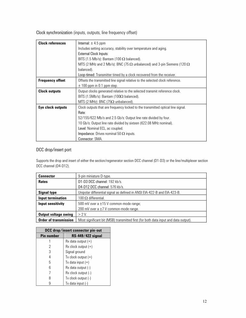
Clock synchronization (inputs, outputs, line frequency offset)
Clock references Internal: ± 4.5 ppm Includes setting accuracy, stability over temperature and aging. External Clock Inputs: BITS (1.5 Mb/s): Bantam (100 Ω balanced). MTS (2 MHz and 2 Mb/s): BNC (75 Ω unbalanced) and 3-pin Siemens (120 Ω balanced). Loop-timed: Transmitter timed by a clock recovered from the receiver.
Frequency offset Offsets the transmitted line signal relative to the selected clock reference. ± 100 ppm in 0.1 ppm step.
Clock outputs Output clocks generated relative to the selected transmit reference clock. BITS (1.5Mb/s): Bantam (100Ω balanced). MTS (2 MHz): BNC (75Ω unbalanced).
Eye clock outputs Clock outputs that are frequency locked to the transmitted optical line signal. Rate: 52/155/622 Mb/s and 2.5 Gb/s: Output line rate divided by four. 10 Gb/s: Output line rate divided by sixteen (622.08 MHz nominal). Level: Nominal ECL, ac coupled. Impedance: Drives nominal 50 Ω inputs. Connector: SMA.
DCC drop/insert port Supports the drop and insert of either the section/regenerator section DCC channel (D1-D3) or the line/multiplexer section DCC channel (D4-D12).
Connector 9-pin miniature D-type. Rates D1-D3 DCC channel: 192 kb/s.
D4-D12 DCC channel: 576 kb/s. Signal type Unipolar differential signal as defined in ANSI EIA-422-B and EIA-423-B. Input termination 100 Ω differential. Input sensitivity 500 mV over a ±15 V common-mode range;
200 mV over a ±7 V common-mode range. Output voltage swing > 2 V. Order of transmission Most significant bit (MSB) transmitted first (for both data input and data output).
DCC drop/insert connector pin-out
Pin number RS-449/422 signal 1 2 3 4 5 6 7 8 9
Rx data output (+) Rx clock output (+) Signal ground Tx clock output (+) Tx data input (+) Rx data output (-) Rx clock output (-) Tx clock output (-) Tx data input (-)

Payload signal structures SONET mappings Bulk STS-1 and STS-Nc, VT mappings and DSn/En service mappings supplied as standard.
STS-48cSTS-48c
STS-12cSTS-12c
STS-192cSTS-192c
STS-3cSTS-3c
STS-1STS-1
STS-192STS-192
STS-12STS-12
STS-48STS-48
STS-3STS-3
STS-1SPE
STS-1SPE
STS-192cSPE
STS-192cSPE
OC-48OC-48
OC-12OC-12
OC-192OC-192
OC-3OC-3
OC-1OC-1
VT-2VT-2
VT-1.5VT-1.5
VT-2SPE
VT-2SPE
VT-1.5SPE
VT-1.5SPE
VT groupVT group
Bulk Filled
Bulk Filled
Bulk Filled
Bulk FilledE4 Async
E3 AsyncDS3 AsyncBulk Filled
E1 AsyncE1 Float. byte syncBulk filledDS1 AsyncDS1 Float. byte syncBulk filled
52Mb/s
155Mb/s
STS-48cSPE
STS-48cSPE
STS-12cSPE
STS-12cSPE
STS-3cSPE
STS-3cSPE
622Mb/s
2.5Gb/s
10Gb/s
SDH mappings Bulk C-3, C-4 and C-4-Nc, TU mappings and DSn/En service mappings supplied as standard.
AU-4-16cAU-4-16c
AU-4-4cAU-4-4c
AU-4-64cAU-4-64c
AU-4AU-4
AU-3AU-3
VC-4-16cVC-4-16c
VC-4-4cVC-4-4c
VC-4-64cVC-4-64c
VC-4VC-4
VC-3VC-3
C-4-16cC-4-16c
C-4-4cC-4-4c
C-4-64cC-4-64c
C-4C-4
STM-16STM-16
STM-4STM-4
STM-64STM-64
STM-1STM-1
STM-0STM-0
AUGAUG
TUG-3TUG-3
TU-12TU-12
TU-3TU-3
TU-11TU-11
VC-12VC-12
VC-3VC-3
C-12C-12
C-11C-11
C-3C-3
TUG-2TUG-2
Bulk Filled
Bulk Filled
Bulk Filled
Bulk FilledE4 Async
E3 AsyncDS3 AsyncBulk Filled
E1 AsyncE1 Float. byte syncBulk filled
DS1 AsyncDS1 Float. byte syncBulk filled
VC-11VC-11
13

14
DSn/PDH frame formats and channel structures Supports generation and analysis of framed, channel structured (mux/demux) and unframed test signals.
Signal Framing Channel structures DS1 SF (D4), ESF, SLC-96, no frame, bit 56 kb/s, 64 kb/s, n x 56 kb/s,
n x 64 kb/s DS3 M13, C-bit DS1, 2 Mb/s, 56 kb/s, 64 kb/s,
n x 56 kb/s, n x 64 kb/s 2 Mb/s PCM30, PCM30CRC, PCM31,
PCM31CRC 64 kb/s, n x 64 kb/s
8 Mb/s ITU-T G.742 2 Mb/s, 64 kb/s, n x 64 kb/s
34 Mb/s ITU-T G.751 8 Mb/s, 2 Mb/s, 64 kb/s, n x 64 kb/s
140 Mb/s ITU-T G.751 34 Mb/s, 8 Mb/s, 2 Mb/s, 64 kb/s, n x 64 kb/s
Test patterns
PRBS 29–1, 211–1(1), 215–1, 220–1(1), QRSS (2), 223–1, 231–1(3). Polarity control: Inverted, non-inverted.
Word All 1’s, All 0’s, 1010, 1000, 16-bit word.
Additional DS1 patterns
3-in-24, 1-in-8, 2-in-8, 55-octet (Daly).
Notes: 1. Not provided for STS-192c/C-4-64c bulk payloads. 2. Non-inverted only. Provided for DSn signals (including 56/64 kb/s channel testing) and VT1.5 bulk payloads by J2129A. 3. Provided for bulk mapped STS-N(c) and C-4-N(c) payloads.

15
Measurements Error measurements
Measurement control Manual, single, timed start. Basic results Error count, error ratio.
Provided for the total measurement period and the most recent (last) measurement second.
SONET TOH: Frame (A1, A2), CV-S (B1), CV-L (B2), CV-LFE (REI-L). STS path: CV-P (B3), CV-PFE (REI-P). Bulk payload: Bit. Signal: BPV (STS-1 and STS-3 interfaces). VT: CV-V(V5), CV-VFE(REI-V). DSn/En payload: See DSn and PDH (En) measurements for details.
SDH SOH: Frame (A1A2), B1, B2, MS-REI. HO-path: B3, HP-REI. Tandem path (VC-3/4 and VC-4-Nc): TC-REI, TC-OEI, TC-IEC. Bulk payload: Bit. Signal: Code (STM-0e and STM-1e interfaces). LO-path: B3 (VC-3), BIP-2; LP-REI Tandem path (VC-11/12): TC-REI, TC-OEI, N2-BIP PDH/DSn payload: See PDH and DSn measurements for details.
DSn
DS1: BPV, frame, CRC6, bit. DS3: BPV, frame, P-bit, CP-bit, FEBE, bit.
PDH (En)
2 Mb/s: Code, frame, CRC4, E-bit, bit. 8Mb/s and 34 Mb/s: Code, frame, bit. 140 Mb/s: Frame, bit.
Performance analysis G.826, G.828. G.821, M.2100, M.2101, M2101.1, M.2110, M.2120.

16
Alarm detection and measurement
Results Alarm seconds. Provided for all supported alarm except power loss and clock loss.
Alarm LEDs Front panel LEDs: Red/green: Signal, frame (all levels of framing), errors (any error type), pattern. Red: SONET/SDH (any SONET/SDH alarm), DSn (any DSn alarm), PDH (any PDH alarm), history (any alarm earlier in measurement period). Virtual LEDs (accesses via front panel ‘Show More’ key): Graphical alarm display showing status information (including history) for all supported alarm types.
SONET Signal: LOS. TOH: LOF, OOF, AIS-L, RDI-L, K1/K2 change. STS path: LOP-P, LOP-C, AIS-P, AIS-C, UNEQ-P, RDI-P, RDI-P-P, RDI-P-S, RDI-P-C, STS pointer adjustment. Payload: Pattern loss. Other: Clock loss, power loss. VT path: H4-LOM, P1P2 Loss, LOP-V, AIS-V, UNEQ-V, RDI-V, RDI-V-P, RDI-V-S, RDI-V-C, RFI-V, VT pointer adjustment. DSn/En payload: See DSn and PDH (En) alarms for details.
SDH Signal: LOS. SOH: LOF, OOF, MS-AIS, MS-RDI, K1/K2 change. HO-path: AU-LOP, AU-LOP-C, AU-AIS, HP-UNEQ, HP-RDI, VC-AIS, AU pointer adjustment. Payload: Pattern loss Tandem path (VC-3/4 and VC-4-Nc): TC-RDI, TC-ODI, IncAIS, TC-OOM, TC-UNEQ. Other: Clock loss, power loss LO-path: H4-LOM, TU-AIS, TU-LOP, LP-UNEQ, LP-RDI, LP-RFI, TU pointer adjustment. Tandem path (VC-11/12): TC-RDI, TC-ODI, IncAIS, TC-OOM, TC-UNEQ. PDH/DSn payload: See PDH and DSn alarms for details.
DSn
DS1: LOS, OOF, AIS, RAI, excess zeros, pattern loss. DS3: LOS, OOF, LOMF, AIS, RAI, idle, DS3 framing mismatch, DS2 LOF, excess zeros, pattern loss.
PDH (En)
2 Mb/s: LOS, LOF, LOMF, AIS, RDI, RDI (MF), minor alarm, pattern loss. 8 /34/140 Mb/s: LOS, LOF, AIS, RDI, minor alarm, pattern loss.

17
Additional measurements
Optical power Supported for all optical receive rates. Ranges: 10 Gb/s: -3dBm to –25 dBm. 10 Gb/s (SR): -1 to –14 dBm 2.5 Gb/s: 0 dBm to –28 dBm. 622 Mb/s and below: 0 dBm to –30 dBm. Accuracy: 10 Gb/s: ± 1.5 dB. 10 Gb/s (SR): ± 2dB 2.5 Gb/s: ± 2 dB. 622 Mb/s and below: ± 1 dB. Resolution: 0.1 dB.
Line frequency Supported for all optical and electrical receive rates. Results: Frequency (Hz), Offset (Hz and ppm). Accuracy: ± 4.5 ppm. Resolution: Frequency: 1 Hz (up to 622 Mb/s), 0.1 kHz (2.5 Gb/s and 10 Gb/s). Offset: 0.1 ppm.
Pointer measurements Supported for both STS/AU and VT/TU pointers. Results: Pointer value, increment count, decrement count, increment seconds, decrement seconds, NDF seconds, missing NDF seconds, SPE/VC offset (in ppm).
Electrical level
Supported for all electrical receive signals up to 52Mb/s. Results: +Vpk, -Vpk, Vpk-pk; +dBdsx, -dBdsx, dBdsx. Accuracy: ± 5%.
Service disruption
Measures the duration of an error burst detected in the received test pattern (not available for word patterns). Supported for all SONET/SDH mappings and DSn/PDH signals. Results: Longest burst, shortest burst, last burst. Range: 50 µs to 2 s. Accuracy: ± 100 µs plus the sum of the applicable re-framing times. Resolution: 1 µs. Re-framing time (maximum): SONET/SDH: 250 µs; STS/AU Pointer: 500 µs; H4 multiframe (VT/TU): 1000 µs VT/TU Pointer: 2000 µs; PDH framer: 125 µs.
Delay
Round trip delay measurement. Supported for all DSn and PDH signals, both as a line signal and as a mapped payload in SONET/SDH. Range: 0 to 1999.999 ms. Resolution: 1 µs.
Pulse mask
Supported for electrical receive signals up to 52 Mb/s, except 8Mb/s. Rates: DS1/3; 2/34 Mb/s; STS-1/STM-0e. Pulse polarity: Evaluates both positive and negative pulses. Results: Graphical display versus selected mask (with pass/fail result), level (Vpk), level ratio (ratio of positive to negative pulse levels), pulse width (ns), pulse width ratio (ratio of positive to negative pulse widths). Masks: T1.102, T1.404, GR-499, GR-253-CORE, G.703, off.

18
SignalWizard (all-channel testing)
Line rates SONET: OC-1/3/12/48/192, STS-1/3. SDH: STM-0/1/4/16/64o, STM-0/1e. DSn: DS3, DS1. PDH: 140Mb/s, 34Mb/s, 8Mb/s, 2Mb/s.
Channel sizes Supports detection and simultaneous monitoring of any ‘mix’ of the following channel types: SONET: STS-1, STS-Nc (where N = 3, 12, 48, 192). SDH: AU-3, AU-4, AU-4-Nc (where N = 4, 16, 64). Note: SignalWizard will identify STS/AU channels of any size (for example STS-24c, AU-4-8c). However, error and alarm results will only be provided for the channel types identified above.
Signal discovery and monitoring
Discovers the line rate and STS/AU channel structure of a received signal. Monitors the line signal for:
CV-S (B1), CV-L (B2), CV-LFE (MS-REI) errors. LOS, LOF, OOF, AIS-L (MS-AIS), RDI-L (MS-RDI). Signal power/level. Synchronization status (S1) message. J0 section trace message.
Simultaneously monitors each STS/AU channel for: CV-P (B3), CV-PFE (HP-REI) errors. AIS-P (AU-AIS), LOP-P (AU-LOP), RDI-P (HP-RDI) alarms. Payload mapping type and VT payload defects (C2 signal label). Pointer activity. J1 path trace message.
Discovers and simultaneously monitors all VT/TU channels in a selected STS/AU for: CV-V (BIP-2), CV-VFE (LP-REI) errors. AIS-V (TU-AIS), LOP-V (TU-LOP), RFI-V (LP-RFI), RDI-V (LP-RDI) alarms. Payload mapping type (V5 signal label). Pointer activity. J2 path trace message.
VT/TU channels in other STS/AU channels are scanned on a sequential basis. STS/AU channel viewer display
Results are clearly presented on a colour-coded graphical display that shows:
Line rate and power/level of the received signal. Status indicators (including history) for each line/section error and alarm. Text decode of synchronization status (S1) and J0 section trace. For each STS/AU channels:
Channel size and channel traffic information (equipped/unequipped and channels carrying VT/TU payloads). Aggregated error/alarm status (including history) and pointer activity.
For a selected STS/AU channel: Status indicators (including history) for each channel error/alarm. Pointer activity. The payload mapping being carried (C2 signal label decode). J1 path trace message.
For each VT/TU channel in a selected STS/AU: Channel size and channel traffic information (equipped/unequipped). Aggregated error/alarm status (including history) and pointer activity.

19
For a selected VT/TU channel:
Status indicators (including history) for each channel error and alarm. The payload mapping being carried (V5 signal label decode). Pointer activity.
J2 path trace message. PDH/DSn Channel Scan
Automatically discover line rate, framing and structure of a received PDH/DSn signal. Automatically discover framing and structure of PDH/DSn signal contained within a SONET/SDH signal. Sequentially monitors each channel for:
140Mb/s, 34Mb/s, 8Mb/s: AIS, LOF, RAI 2Mb/s: AIS, LOF, RAI, CAS, CRC, RMF DS3: AIS, OOF, RAI (XBIT), FM, Idle, LOMF DS2: AIS, OOF, LOMF DS1: AIS, OOF, RAI (Yellow)
Display channel numbering and status indication (including history) for each PDH/DSn error or alarm.

20
SignalWizard (continued)
Path routing test facilities
Overview of received path trace messages:
Tabular display showing the J1 path trace message associated with each STS/AU channel in the received line signal. Tabular display showing the J2 path trace message associated with each VT/TU channel in a selected STS/AU.
Search for specified path trace message: Identifies channel that is carrying a user-specified path trace message. For J1 messages, the search is performed on all STS/AU channels in received signal. The J2 message search is performed on:
All VT/TU channels in a selected STS/AU channel. All VT/TU channels in all STS/AU channels.
Search can be performed using any sub-string contained in the target path trace message. Search results report up to 25 matches.
Channel traffic overview
Tabular display that lists for each STS/AU channel in the received signal:
Channel number. Channel size/type. The payload mapping being carried. J1 path trace message.
Tabular display that lists for each VT/TU channel in a selected STS/AU: Channel number. Channel size/type. The payload mapping being carried. J2 path trace message.

21
Error generation
SONET Signal: Data(1) TOH: Frame (A1A2), CV-S (B1), CV-L (B2), REI-L. (CV-LFE) (2) STS path: CV-P (B3), CV-PFE (REI-P), CV-IEC (STS path IEC). Bulk payload: Bit. Signal: BPV (STS-1). VT path: CV-V (V5), REI-V (CV-VFE). DSn/En payload: See DSn and PDH (En) error add for details. Error Control: Single, error all(3), M.P x 10-n (where M.P = 0.1 to 9.9 in 0.1 steps; n = 3 to 9)(4), N-in-4(5), N-in-T(6).
SDH Signal: Data(1) SOH: Frame (A1A2), B1, B2, MS-REI.(2) HO-path: B3, HP-REI, HP-IEC. Tandem path (VC-3/4 and VC-4-Nc): TC-REI, TC-OEI. Bulk payload: Bit Signal: Code (STM-0e). LO-path: B3 (VC-3), BIP-2 (VC-1/2); LP-REI. Tandem path (VC-11/12): TC-REI, TC-OEI, N2-BIP. PDH/DSn payload: See PDH and DSn error add for details. Error Control: Single, Error All (3), M.P x 10 -n (where M.P = 0.1 to 9.9 in 0.1 steps; n = 3 to 9) (4), N-in-4 (5), N-in-T (7)
DSn
DS1: BPV(8), excess zeros(9), frame, CRC6, bit. DS3: BPV (8), excess zeros(9), frame, MFAS, P-bit, CP-bit, FEBE, bit. Error control: Single, M.P x 10 -n (where M.P = 0.1 to 9.9 in 0.1 steps, and n = 3 to 9)(4), N-in-4(10) , N-in-6(11)
PDH (En)
2 Mb/s: Code(8), frame, CRC4, E-bit, bit. 8 Mb/s and 34 Mb/s: Code(8), frame, bit. 140 Mb/s: frame, bit. Error control: Single, M.P x 10 -n (where M.P = 0.1 to 9.9 in 0.1 steps, and n = 3 to 9)(4), N-in-4(10).
Notes: 1. Errors transmitted pseudo-randomly in the signal frame. 2. For OC-192/STM-64, supports both the ‘M1 only’ and ‘M0+M1’ options of the standards. 3. Not supported for data, frame, BPV/code or bit. 4. The maximum error rate for any error type is 1 x 10⁻³ or the maximum error rate supported by the error type (its saturation value), whichever
is the lower. 5. Supported for frame (A1A2) errors. N = 1 to 4. 6. B2 errors only. N errors transmitted during time T (T = 10 ms to 1000 s in decade steps; N = 0 to 640 x n errors, where n is the hierarchical
level of the STS-n signal). 7. B2 errors only. N errors transmitted during time T (T = 10 ms to 1000 s in decade steps;
N = 0 to 640 errors for STM-0, and 0 to 1920 x n errors for all other line rates, where n is the hierarchical level of the STM-n signal). 8. Not available when signal is a mapped payload in SONET/SDH or a channel within a higher rate DSn/PDH signal. 9. Single burst of 3 to 16 zeros (user selectable) transmitted without line coding. 10. Supported for DS3 frame, DS3 MFAS and PDH frame errors. N = 1 to 4. 11. Supported for DS1 frame errors. N = 1 to 6.

22
Alarm generation
Alarm control On/off. SONET Signal: LOS.
TOH: LOF, OOF, AIS-L, RDI-L. STS path: AIS-P, LOP-P, RDI-P, RDI-P-P, RDI-P-S, RDI-P-C, UNEQ-P.VT path: H4-LOM, AIS-V, LOP-V, RDI-V, RDI-V-P, RDI-V-S, RDI-V-C, RFI-V, UNEQ-V.
SDH Signal: LOS. SOH: LOF, OOF, MS-AIS, MS-RDI. HO-path: AU-AIS, AU-LOP, HP-RDI, HP-UNEQ. Tandem path (VC-3/4 and VC-4-Nc): TC-RDI, TC-ODI, VC-AIS, TC-UNEQ.LO-path: H4-LOM, TU-AIS, TU-LOP, LP-RDI, LP-RFI, LP-UNEQ. Tandem path (VC-11/12): TC-RDI, TC-ODI, VC-AIS, TC-UNEQ.
DSn
DS1: LOS, OOF, AIS, RAI. DS3: LOS, OOF, AIS, RAI, idle.
PDH (En)
2 Mb/s: LOS, LOF, LOMF, AIS, RDI, RDI (MF), minor alarm. 8 /34/140 Mb/s: LOS, LOF, AIS, RDI, minor alarm.
SONET/SDH overhead testing
Overhead setup All TOH/SOH, STS-path/HO-path, and VT-path/LO-path overhead bytes user programmable in hexadecimal. Restrictions: B1, B2, B3, H1 (SS-bits programmable), H2, H3, V1 to V4, V5 (bits 5-7 programmable).
Overhead monitor Displays all TOH/SOH overhead bytes in a selected STS-3/STM-1group, plus all STS-path/HO-path and VT path/LO-path overhead bytes. Received byte values are presented in hexadecimal.
APS/MSP messages (K1K2)
Text-based setup and monitoring of APS/MSP messages. Linear: Messages comply with Telcordia GR-253-CORE Issue 3 and ITU-T G.783. Ring: Messages comply with Telcordia GR-1230 and ITU-T G.841.
Trace messages (J0, J1, J2, TC-APId)
Text-based setup and monitoring of all trace messages (J0, J1, J2, TC-APId (VC-3/4, VC-4-Nc), TC-APId (VC-11/12). Message formats: J0/J1/J2: Selectable as 16-byte or 64-byte format. TC-APId (SDH only): 16-byte format.
Synchronization status message (S1)
Text-based setup and monitoring of Synchronization Status messages. Messages comply with Telcordia GR-253-CORE Issue 3 and ITU-T G.707 (04/00 draft).
Signal labels (C2, V5) Text-based setup and monitoring of payload signal labels (both STS path/HO-path and VT path/LO-path). Signal labels comply with Telcordia GR-253-CORE Issue 3 and ITU-T G.707 (04/00 draft).

23
SONET/SDH pointer adjustment control The following pointer adjustment controls are provided as standard for STS-Nc/AU-4-Nc, STS/AU payload pointers and VT/TU pointers.
New pointer Transmits a new pointer address with or without a new delta flag (NDF). Supports setting of any valid pointer value.
Burst Single burst of adjustments transmitted in a selected pointer. Adjustment polarity: Incrementing, decrementing, alternating. Burst size: STS/AU and STS-Nc/AU-4-Nc: 1 to 10. VT/TU: 1 to 5. Separation of adjustments in burst: STS/AU and STS-Nc/AU-4-Nc: 4 frames (500µs). VT/TU: 4 multiframes (2 ms).
Periodic sequence Periodic sequence of pointer adjustments created by generating a frequency offset between the line and SPE/VC clocks. Clock control: User selectable as either:
1. SPE/VC clock offset, line clock locked to reference. 2. Line clock offset, SPE/VC clock locked to reference.
Offset: User selectable in the range ± 100 ppm. Setting resolution: 0.1 ppm. Accuracy: 0.02 ppm.
Drop/insert capabilities
DCC channels Supports the drop-insert of a selected DCC channel in SONET/SDH via a serial datacom interface. DCC channel: D1-D3 (192 kb/s) or D4-D12 (576 kb/s). Connector: 9-pin miniature (see DCC connector for details). Interface type: DCE (drop and insert clocks supplied by test set).
DSn/PDH to/from SONET
Supports the external drop/insert of asynchronous mapped DSn/PDH payloads. Drop/insert is performed via the instrument’s DSn/PDH electrical test ports. Supported rates: DS1, E1 (2Mb/s), DS3.
DSn/PDH to/from SDH
Supports the external drop/insert of asynchronous mapped DSn/PDH payloads. Drop/insert performed via the instrument’s DSn/PDH electrical test ports. Supported rates: DS1, 2 Mb/s, 34 Mb/s, DS3, 140 Mb/s.
DSn/PDH to/from DSn/PDH
Supports the external drop/insert of a DS1 or 2 Mb/s channel to/from a higher-rate DSn/PDH signal. Drop-insert performed via the instrument’s DSn/PDH electrical test ports. Supported rates: DS1 to/from DS3; 2 Mb/s(1) to/from 8/34/140 Mb/s or DS3.
Voice drop
Allows the traffic in a selected 56 kb/s or 64 kb/s timeslot carried within a DS1 or 2 Mb/s signal to be dropped to an internal speaker. The DS1 or 2 Mb/s signal can be at the primary signal rate or carried within a higher-rate line signal (SONET/SDH or DS3/PDH). Coding: A-law (2 Mb/s), µ-law (DS1).
Note: 2 Mb/s drop/insert to/from an 8/34/140 Mb/s signal is performed via the 120 Ω balanced test ports (3-pin Siemens connectors)

24
Thru-mode testing
Non-intrusive (Transparent) Receive signal passes unaltered through test set. All receiver test facilities are available. Rates: SONET: OC-1, OC-12, OC-48, OC-192, STS-1, STS-3. SDH: STM-0o, STM-4o, STM-16o, STM-64o, STM-0e, STM-1e. Note: J2129A required for support of STS1/3 and STM-0/1e interfaces. Intrusive (Overhead Overwrite) In this configuration the signal at the receiver is replicated at the transmitter output. Full receiver capability is available, while the instrument also allows for selected bytes of the SOH/RSOH, the LOH/MSOH and the high POH to be modified – J0, J1, S1, C2, K1, K2,
Transmitted B1, B2 and B3 BIP values are recalculated before re-transmission. Thru Mode Error Addition SDH SONET Entire Frame error Fame (A1, A2) error B1 BIP error CV-S B2 BIP error CV-L MS REI error REI-L B3 BIP error CV-P HP REI error REI-P TC-IEC (VC-4-Xc/VC-4/VC-3) error Not applicable TC-REI (VC-4-Xc/VC-4/VC-3) error Not applicable TC-OEI (VC-4-Xc/VC-4/VC-3) error Not applicable When an error is added to any byte, the whole byte is overwritten. Thru Mode Alarm Generation SDH SONET LOS alarm LOF alarm OOF alarm SEF MS-AIS alarm AIS-L MS-RDI alarm RDI-L AU-AIS alarm AIS-P AU-AIS-C AIS-C HP-RDI alarm RDI-P AU-LOP alarm LOP-P AU-LOP-C alarm LOP-C HP-UNEQ alarm UNEQ-P
SONET/SDH
VC-AIS alarm Not applicable

25
TC-RDI (VC-4-Xc/VC-4/VC-3) alarm Not applicable TC-ODI (VC-4-Xc/VC-4/VC-3) alarm Not applicable TC-UNEQ (VC-4-Xc/VC-4/VC-3) alarm Not applicable TC-OOM (VC-4-Xc/VC-4/VC-3) alarm Not applicable
TC-IAIS (VC-4-Xc/VC-4/VC-3) alarm Not applicable DSn/PDH
Receive signal passes unaltered through test set. All receiver test facilities are available. Rates: DS1, DS3, 2Mb/s, 8Mb/s, 34Mb/s, 140Mb/s.
DS1 loopcodes and DS3 FEAC messages
DS1 loopcodes Transmits and monitors both in-band and out-of-band DS1 loopcodes. In-band: Line, payload, network, user (selectable in range 3 to 8 bits). Transmit: Selected code transmitted for 8 seconds (nominal). Monitor: Indicates the detection of a selected loop-up and loop-down code. Displays the last valid loopcode received. Out-of-band: Line, payload, network, universal, user (11111111 0xxxxxx0). Transmit: Selected code transmitted either continuously or in a burst of n-messages (where n is selectable in the range 1 to 15). Monitor: Displays in decode form the two most recently received loopcodes (current and previous).
DS3 FEAC messages Applies to DS3 C-bit framed signals. Transmits and monitors loopback and alarm/status codes as per ANSI T1.107-1995. Loopback code transmit: Transmits any user selected loopback code as a single burst of ‘N loopback codes’ and ‘M messages’ (where N and M are selectable in the range 1 to 15). Alarm/status code transmit: Transmits any ANSI T1.107-1995 message or any user specified code (0xxxxxx0 11111111), either continuously or in a single burst (selectable in the range 1 to 15). Monitor: Displays in decoded form the two most recently received FEAC messages (current and previous).
PDH spare-bits testing Supports user-programming and monitoring of PDH frame spare-bits.
2 Mb/s (non-CRC framing)
Si-bit (timeslot 0, bit 1); Sa4 to Sa8 (NFAS timeslot); timeslot 16 (MFAS) bits 5, 7 and 8 (PCM30 framing).
2 Mb/s (CRC framing)
E-bits (Si-bit in frames 13 and 15); 8-bit pattern in each NFAS Sa-bit (Sa4 to Sa8); timeslot 16 (MFAS) bits 5, 7 and 8 (PCM30CRC framing).
8/34/140 Mb/s 8 Mb/s and 34 Mb/s: FAS bit 12. 140 Mb/s: FAS bits 14 to 16.

26
Signaling-bits testing
2 Mb/s Framing formats: PCM30, PCM30CRC (CAS). Transmit: User-programmed value transmitted in ABCD signaling-bits associated with all 30-channels. Monitor: Displays ABCD signaling-bits associated with all 30-channels.
DS1 Frame formats: SF (D4), ESF, SLC-96 Channel type: 56 kb/s structured timeslots. Transmit: User-programmed value transmitted in AB or ABCD signaling-bits associated with all 24-channels. Monitor: Displays AB or ABCD signaling-bits associated with all 24-channels.
General features
Help facilities On-line user documentation: Accessed via front panel key. Context-sensitive help: Provided for each control-field on a dedicated line of the instrument’s display. The displayed help information automatically tracks the cursor. User-help documentation: Supports the installation (from floppy disk) of up to 1.44 Mbytes of user-authored help files in the instrument’s non-volatile memory. This help information is available in addition to that provided as standard.
Stored configurations Provides storage for ten instrument configurations (one factory-default configuration plus nine user configurations) in non-volatile memory. Additional instrument configurations can be saved to and recalled from the floppy disk.
Graphical results The following graphical results are available for display during a measurement: STS/AU pointer: Line graph of STS/AU pointer address versus time. Errors: Bar graph for each supported error types versus time. Alarms: Line graph for each supported alarm type versus time. VT/TU pointer: Line graph of VT/TU pointer address versus time. Time resolution: 1-second, 1 min, 1 hr, 12hr, 1 day, 2-7 days. Storage: Up to 10 sets (or 10 Mbytes in total) of graphical results can be saved in the instrument’s non-volatile memory.
Result logging Supports logging of results during a measurement to a printer or to a file in the instrument’s non-volatile memory. Logged information: Instrument settings, time and date, period-results, end-of-measurement results (the results logged are user selectable). Logging period: 10-minutes, 1-hour, 24-hours, user-defined (in ranges 10 to 99-minutes; 1 to 99-hours).
Printing
Supports printing of logged results and screen dumps via USB port.
Beep-on-error Audible beep emitted on detection of any valid error-type. Control: Off/on (with user controlled volume).

27
General specifications
Display 8.4” VGA display (TFT active matrix).
Floppy disk 1.44 Mb IBM-compatible. Supported facilities include: Stored configurations: Save and recall of instrument configurations. Logged results: Saving the results generated during measurement logging. Results saved in Windows®-compatible ‘plain text’ format. Screen dumps: Saving the current instrument display in Windows-compatible .BMP format. User-help files: Downloading user-help files to the instrument.
Remote control interfaces LAN (10/100BaseT), RS-232, GP-IB. Peripheral interfaces
PS/2 keyboard; PS/2 mouse 2 x USB (for printer).
Remote graphical user interface
A JavaTM application connected remotely via LAN or modem. Compatible with PC-based Windows® operating systems.
Firmware upgrades
Downloaded to the test set from a PC via LAN or RS-232 interface.
AC power
Voltage range: 90 to 260 Vac nominal (auto-ranging). Frequency range: 47 to 63 Hz. Power: 150 VA (J2126A); 250 VA (J2127A).
Environmental
Operating temperature: 0 to 45 oC (32 to 113 oF). Storage temperature: -20 to 70 oC (-4 to 158 oF). Humidity: 15% to 90% relative humidity at 40 oC (104 oF).
Dimensions (approximate) (height x width x depth)
J2126A: 180 mm x 331 mm x 224 mm (7.1” x 13” x 8.8”). J2127A: 180 mm x 331 mm x 288 mm (7.1” x 13” x 11.3”). J2127A (extended chassis): 180 mm x 331 mm x 402 mm (7.1” x 13” x 15.8”)
Weight (approximate) J2126A: 8.7 kg (19 lbs) (covers all rates to 2.5 Gb/s). J2127A: 11.2 kg (25 lbs) (covers all rates to 10 Gb/s). J2127A (extended chassis): 13.5 kg (30 lbs) (covers all rates to 10Gb/s).
Warranty
3-year as standard. Option W50: Extends warranty period to 5-years.
Calibration cycle
2-years.
28
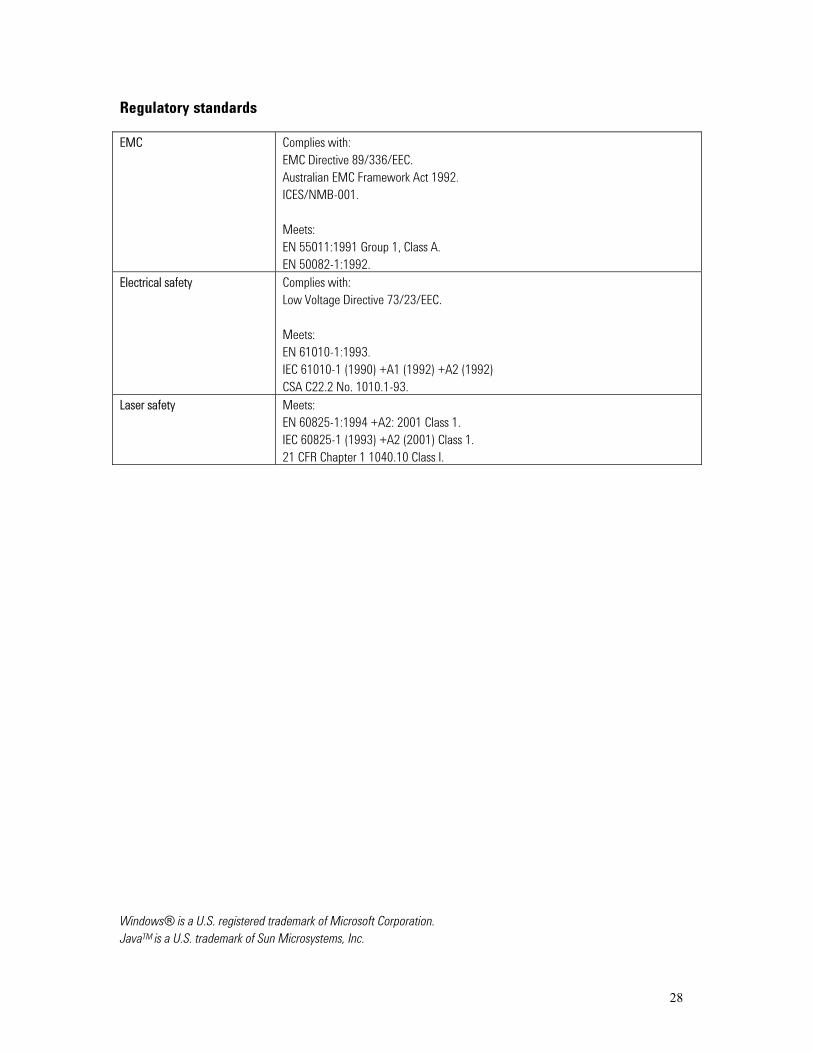
Regulatory standards EMC Complies with:
EMC Directive 89/336/EEC. Australian EMC Framework Act 1992. ICES/NMB-001. Meets: EN 55011:1991 Group 1, Class A. EN 50082-1:1992.
Electrical safety Complies with: Low Voltage Directive 73/23/EEC. Meets: EN 61010-1:1993. IEC 61010-1 (1990) +A1 (1992) +A2 (1992) CSA C22.2 No. 1010.1-93.
Laser safety Meets: EN 60825-1:1994 +A2: 2001 Class 1. IEC 60825-1 (1993) +A2 (2001) Class 1. 21 CFR Chapter 1 1040.10 Class I.
Windows® is a U.S. registered trademark of Microsoft Corporation. JavaTM is a U.S. trademark of Sun Microsystems, Inc.

Agilent Technologies’Test and Measurement Support, Services, and Assistance Agilent Technologies aims to maximize the value you receive, while minimizing your risk and problems. We strive to ensure that you get the test and measurement capabilities you paid for and obtain the support you need. Our extensive support resources and services can help you choose the right Agilent products for your applications and apply them successfully. Every instrument and system we sell has a global warranty. Support is available for at least five years beyond the production life of the product. Two concepts underlie Agilent’s overall support policy: “Our Promise” and “Your Advantage.” Our Promise Our Promise means your Agilent test and measurement equipment will meet its advertised performance and functionality. When you are choosing new equipment, we will help you with product information, including realistic performance specifications and practical recommendations from experienced test engineers. When you use Agilent equipment, we can verify that it works properly, help with product operation, and provide basic measurement assistance for the use of specified capabilities, at no extra cost upon request. Many self-help tools are available. Your Advantage Your Advantage means that Agilent offers a wide range of additional expert test and measurement services, which you can purchase according to your unique technical and business needs. Solve problems efficiently and gain a competitive edge by contracting with us for calibration, extra-cost upgrades, out-of-warranty repairs, and on-site education and training, as well as design, system integration, project management, and other professional engineering services. Experienced Agilent engineers and technicians worldwide can help you maximize your productivity, optimize the return on investment of your Agilent instruments and systems, and obtain dependable measurement accuracy for the life of those products.
By internet, phone, or fax, get assistance with all your test & measurement needs Online assistance: www.agilent.com/find/assist Phone or Fax United States: (tel) 1 800 452 4844 Canada: (tel) 1 877 894 4414 (fax) (905) 282 6495 China: (tel) 800 810 0189 (fax) 1 0800 650 0121 Europe: (tel) (31 20) 547 2323 (fax) (31 20) 547 2390 Japan: (tel) (81) 426 56 7832 (fax) (81) 426 56 7840 Korea: (tel) 82 2) 2004 5004 (fax) (82 2) 2004 5115 Latin America: (tel) (305) 269 7500 (fax) (305) 269 7599 Taiwan: (tel) 080 004 7866 (fax) (886 2) 2545 6723 Other Asia Pacific Countries: (tel) (65) 375 8100 (fax) (65) 836 0252 Email: [email protected] Product specifications and descriptions in this document subject to change without notice. © Agilent Technologies, Inc. 2002 Printed in UK, Aug, 2002 5988-2570EN
29