A GUIDE TO UNMETERED - Elexon
44
A Guide to Unmetered Supplies Under the BSC 17 March 2021 Version 23.0 © Elexon 2021 Page 0 of 43 Intellectual Property Rights, Copyright and Disclaimer The copyright and other intellectual property rights in this document are vested in Elexon or appear with the consent of the copyright owner. These materials are made available for you for the purposes of your participation in the electricity industry. If you have an interest in the electricity industry, you may view, download, copy, distribute, modify, transmit, publish, sell or create derivative works (in whatever format) from this document or in other cases use for personal academic or other non-commercial purposes. All copyright and other proprietary notices contained in the document must be retained on any copy you make. All other rights of the copyright owner not expressly dealt with above are reserved. No representation, warranty or guarantee is made that the information in this document is accurate or complete. While care is taken in the collection and provision of this information, Elexon Limited shall not be liable for any errors, omissions, misstatements or mistakes in any information or damages resulting from the use of this information or action taken in reliance on it. A GUIDE TO UNMETERED SUPPLIES UNDER THE BSC Operational Information Document Public
Transcript of A GUIDE TO UNMETERED - Elexon
A Guide to Unmetered Supplies Under the BSC
17 March 2021 Version 23.0
© Elexon 2021 Page 0 of 43
Intellectual Property Rights, Copyright and Disclaimer
The copyright and other intellectual property rights in this document are vested in Elexon or appear with the
consent of the copyright owner. These materials are made available for you for the purposes of your
participation in the electricity industry. If you have an interest in the electricity industry, you may view, download,
copy, distribute, modify, transmit, publish, sell or create derivative works (in whatever format) from this
document or in other cases use for personal academic or other non-commercial purposes. All copyright and
other proprietary notices contained in the document must be retained on any copy you make.
All other rights of the copyright owner not expressly dealt with above are reserved.
No representation, warranty or guarantee is made that the information in this document is accurate or complete.
While care is taken in the collection and provision of this information, Elexon Limited shall not be liable for any
errors, omissions, misstatements or mistakes in any information or damages resulting from the use of this
information or action taken in reliance on it.
A G U I D E TO
U N M E T E R E D
S U P P L I E S U N D E R T H E
B S C
Operational Information
Document
Public
A Guide to Unmetered Supplies Under the BSC
17 March 2021 Version 23.0
© Elexon 2021 Page 1 of 43
Contents
Contents 1
1 An introduction to Unmetered Supplies 3
1.1 What are Unmetered Supplies under the BSC? 3
1.2 What is the purpose of this document? 3
1.3 Before reading on, some key roles and terms explained... 3
1.4 What is Half Hourly (HH) and Non Half Hourly (NHH) Trading? 3
1.4.1 Calculation of the Maximum Demand of an UMS Inventory 4
1.4.2 Half Hourly 5
1.4.3 Non Half Hourly 5
1.5 What are Central Management Systems (CMS)? 5
2 What are Charge Codes? 6
2.1 Why do I need one? 6
2.2 What are discontinued Charge Code structures? 6
2.3 The structure explained 6
2.3.1 Lamps 7
2.3.2 Traffic equipment 10
2.3.3 Miscellaneous equipment 13
2.3.4 Issuing of local or national Miscellaneous Charge Codes 13
2.3.5 Control equipment 16
2.3.6 Highway Message and Indicator Signs - Devices with variable hours 16
3 How do I apply for a Charge Code? 17
3.1 Considerations in respect of Charge Code applications 17
3.2 Test data requirements 18
3.3 Applying to use a range of Generic LED Lighting Charge Codes 19
3.3.1 The structure of Generic LED Lighting Charge Codes 19
3.3.2 Manufacturer Equipment LED Range Spreadsheet 20
3.4 Test procedure for LED Variable Message, Bus Information Signs and signs with variable light levels
20
3.5 Test procedure for Belisha Beacons 21
3.6 Test procedure for CCTV Equipment 21
3.7 Test procedure for Constant Light Output (CLO) 22
3.8 Test procedure for Variable Power Switch Regime (VPSR) Devices 22
3.9 Testing requirements for Wi-Fi Equipment 23
3.10 Testing requirements for 50 Series Electronic Ballasts 23
3.11 Charge Codes for Central Management System (CMS) Equipment 24
3.12 Charge Codes for Speed/red light cameras or equipment that includes cameras 24
4 How are Charge Codes Calculated? 24
4.1 Equipment that is less than 10 Watts 24
A Guide to Unmetered Supplies Under the BSC
17 March 2021 Version 23.0
© Elexon 2021 Page 2 of 43
4.2 Traffic signal heads 24
4.2.1 Continuous green aspects 25
4.2.2 How do I record traffic signal equipment in my inventory? 25
4.2.3 Dimming Traffic Signals 26
4.2.4 Dummy Loads for LED Traffic Lights 26
4.2.5 What are filter signals? 26
4.3 Cable network cabinets (Miscellaneous Codes Starting 813) 27
4.3.1 Legacy arrangement 27
4.3.2 Charge Codes at Cabinet Level 27
4.3.3 Charge Codes at Component Level 27
5 Not used 28
6 Photoelectric Control Unit (PECU) array location and siting guidance 28
6.1 Location of a single array 28
6.1.1 Weighted latitude and longitude of inventory 28
6.1.2 Weighted latitude and longitude of population 28
6.2 Deciding on multiple or single arrays 28
6.3 Hosting and maintenance of the arrays 28
7 What are Switch Regimes? 29
7.1 Hybrid/thermal Photoelectric Control Units (PECUs) 31
7.2 Part night dimming 31
7.3 Variable Power Switch Regime (VPSR) Switch Regimes 32
7.4 Variable Power Switch Regime Spreadsheet 33
7.4.1 Energy calculation for dimming of Generic LED Lighting Charge Codes ending ‘100’ 33
7.5 Highway Message and Indicator Sign operating hours 33
7.6 Valid Combinations of Charge Codes and Switch Regimes 34
7.6.1 Valid Combinations of Equipment Charge Codes and Switch Regimes 34
7.6.2 Valid Combinations of Control Charge Codes and Switch Regimes 37
7.7 Equivalent Meter Default PECU Switch Regimes 38
8. Standard file format for detailed inventories 39
8.1 General comments 39
8.2 Standard file format 40
8.3 Notes on standard inventory format 41
8.4 Notes for Customers on declaring Charge Codes and Switch Regimes for Variable Power Switch
Regime (VPSR) Devices 42
A Guide to Unmetered Supplies Under the BSC
17 March 2021 Version 23.0
© Elexon 2021 Page 3 of 43
1 An introduction to Unmetered Supplies
1.1 What are Unmetered Supplies under the BSC?
An Unmetered Supply (UMS) means a supply of electricity to a particular inventory of equipment in respect of which a
Licensed Distribution System Operator (LDSO) has issued an Unmetered Supply Certificate. For example, this
equipment could be any electrical equipment that draws a current and is connected to the Distribution Network without
a meter, i.e. there is no meter recording its energy consumption, e.g. street lights, traffic signs, zebra crossings, etc.
1.2 What is the purpose of this document?
This document aims to provide guidance on:
What Charge Codes are (unique code representing unmetered equipment)
The meaning of a Charge Code’s structure
The testing required to obtain a Charge Code
How to account for equipment such as traffic signals in Customer inventories
Switch Regime codes (and Part Night dimming)
The difference between Non Half Hourly (NHH) and Half Hourly (HH) trading; and
Other useful operational information relating to Unmetered Supplies under the BSC.
1.3 Before reading on, some key roles and terms explained...
The Customer – A Customer will have entered into an Unmetered Supplies Connection Agreement with a Licensed
Distribution System Operator or been provided with Unmetered Supplies in accordance with the National Terms of
Connection. They are responsible for maintaining a detailed inventory of all their UMS equipment and providing regular
updates to their Unmetered Supplies Operator (UMSO). The Customer is also responsible for contracting with the
Meter Administrator (MA), if the UMS is traded HH under the BSC. The Supplier will appoint the MA for Settlement
purposes. Customers should contact their UMSO if they have any questions on how to submit equipment in their
detailed inventory.
The Unmetered Supplies Operator (UMSO) – The UMSO is part of the LDSO, also known as the Distribution
Business or Network Operator. The UMSO is responsible for looking after all of the Unmetered Supplies on its network.
The UMSO makes new connections and decides what equipment is suitable for treatment as an Unmetered Supply.
The UMSO provides a summarised inventory to the MA for HH traded UMS or calculates an Estimated Annual
Consumption (EAC) for NHH traded UMS.
The Meter Administrator (MA) – is responsible for providing HH consumption data into Settlement. This is the
consumption of a particular Customer in kWh, for each half hour of every day. The Supplier will appoint the MA for
Settlement purposes.
BSCCo (the Balancing and Settlement Code Company, the role fulfilled by Elexon) - is responsible for ensuring
that the processes within BSCP520 ‘Unmetered Supplies Registered in SMRS’ are carried out effectively. BSCCo is
also responsible for issuing Charge Codes and Switch Regimes to Product Manufacturers and Customers such as
Local or Highways Authorities. BSCCo also coordinates the Central Management Systems (CMS) approval process.
Unmetered Supplies User Group (UMSUG) - An expert group reporting to the Supplier Volume Allocation Group
(SVG) advising them on the UMS arrangements under the Balancing and Settlement Code (BSC). Their work includes
reviewing Charge Code applications, advising on changes to the relevant BSC subsidiary documents (e.g. BSCP520),
the resolution of issues and new developments relating to UMS. The UMSUG is chaired by BSCCo and meets on an
ad-hoc basis driven by the SVG and business need.
1.4 What is Half Hourly (HH) and Non Half Hourly (NHH) Trading?
Unmetered inventories are traded either on a NHH or a HH basis. The majority of inventories are traded on a NHH
basis, however, the BSC requires unmetered 100kW Metering Systems to trade on a HH basis where the LDSO has
agreed that the maximum demand is greater than 100kW.
A Guide to Unmetered Supplies Under the BSC
17 March 2021 Version 23.0
© Elexon 2021 Page 4 of 43
The UMSO (as the LDSO’s party agent carrying out its role defined in BSCP520) is responsible for agreeing the
inventory of unmetered equipment with the customer. As part of this activity the maximum demand of the unmetered
inventory must be determined. If it exceeds 100kW then the UMSO will advise the Supplier to arrange with the
Customer for the inventory to be traded on a HH basis.
The Supplier is responsible for making the initial contact with the customer and for ensuring the migration to HH
occurs. Although these responsibilities are that of the Supplier, it may be beneficial for the UMSO to be involved in any
migration activities. The UMSO should wait for confirmation from the Supplier that the customer has been contacted
before starting the process of establishing a new HH inventory.
The Distribution Use of System charging statements currently require that unmetered supplies only transfer from non-
half hourly to half hourly on the 1 April in any year. In April 2021 the charging arrangements will change and they can
transfer at any time.
1.4.1 Calculation of the Maximum Demand of an UMS Inventory
The electrical demand for an inventory will vary during the day as equipment is switched on/off or dimmed. To
determine the maximum demand it will be necessary to decide the time of day when the peak will occur. In an
inventory predominantly for Street Lighting, this is likely to be during the Dusk to Dawn period, whereas an inventory for
Traffic Signals the maximum demand will more likely occur during the day between Dawn and Dusk, when the traffic
signals will be “bright” rather than dimmed at night between Dusk and Dawn.
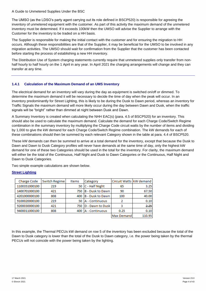
A Summary Inventory is created when calculating the NHH EAC(s) (para. 4.5 of BSCP520) for an inventory. This
should also be used to calculate the maximum demand. Calculate the demand for each Charge Code/Switch Regime
combination in the summary inventory by multiplying the Charge Code circuit watts by the number of items and dividing
by 1,000 to give the kW demand for each Charge Code/Switch Regime combination. The kW demands for each of
these combinations should then be summed by each relevant Category shown in the table at para. 4.4 of BSCP520.
These kW demands can then be summed to arrive at a total demand for the inventory, except that because the Dusk to
Dawn and Dawn to Dusk Category profiles will never have demands at the same time of day, only the highest kW
demand for one of these two Categories should be used in the total for the inventory. For clarity, the maximum demand
will either be the total of the Continuous, Half Night and Dusk to Dawn Categories or the Continuous, Half Night and
Dawn to Dusk Categories.
Two simple example calculations are shown below.
Street Lighting
In this example, the Thermal PECUs kW demand on row 5 of the inventory has been excluded because the total of the
Dawn to Dusk category is lower than the total of the Dusk to Dawn category, i.e. the power being taken by the thermal
PECUs will not coincide with the power being taken by the lighting.

A Guide to Unmetered Supplies Under the BSC
17 March 2021 Version 23.0
© Elexon 2021 Page 5 of 43
Traffic Signals
In this example, the power used by the Vehicle and Pedestrian Aspects at night (dimmed) has been excluded because
it will not coincide with the higher watts (bright) used during the day.
Additionally note the requirements of 1.4.3 below when allocating demand to a category. If allocating dimming traffic
signal equipment to Category A, only the bright circuit watts should be used in the maximum demand calculation.
1.4.2 Half Hourly
HH data is the energy consumption of a Customer in kWh, apportioned into the correct half hour of each day. There
are two methods of calculating half hourly consumptions, dynamic and passive HH trading.
Dynamic HH trading achieves this by use of the data obtained from PECU arrays and/or any CMS. Dynamic data is
actual recorded data such as the switching times of a representative sample of photocells contained in a Photo Electric
Control Unit (PECU) array. Data recorded by a Central Management System (CMS) is also dynamic data, with the
switching times of each individual lamp controlled by the system and/or power levels being recorded (see What are
Central Management Systems (CMS)?).
Passive HH achieves this by using the calculated Sunrise/Sunset times. Passive HH does not use any dynamic data.
In order to trade HH an MA must be appointed. The MA is appointed by the Supplier and contracted by the Customer
(who may have chosen to operate HH).
1.4.3 Non Half Hourly
NHH trading does not use any dynamic data and instead uses an estimated number of annual hours for each type of
photocell Switch Regime. These annual hours are published by BSCCo in the Switch Regime Spreadsheet. The
appropriate Category for each Switch Regime is defined in the Switch Regime Spreadsheet. The Category shown in
the spreadsheet is not appropriate for certain load types:
Traffic signal equipment, particularly where dimming is in use, so traffic signal consumption should always be
regarded as either Category A – continuous; or split in proportion across Category B – Dusk to Dawn &
Category D – Dawn to Dusk.
Thermal & hybrid photocells daytime load would be allocated to Category D – Dawn to Dusk.
All other equipment controllers (electronic photocells, time switches, etc.) would be allocated to Category A –
continuous.
1.5 What are Central Management Systems (CMS)?
CMS are dynamic controls which manage the electrical load of UMS equipment that can operate at multiple on/off
times and/or dimming levels. A CMS records these events, which the MA then uses to calculate consumption data for
Settlement. This is a form of dynamic HH Settlement.
Different CMS designs operate in different ways. Some only provide an instruction to the controlled equipment and
assume the equipment reacts to the instruction. Others receive feedback from the controlled equipment. Some designs
measure the energy consumed and return information which reflects the actual consumption.
A Guide to Unmetered Supplies Under the BSC
17 March 2021 Version 23.0
© Elexon 2021 Page 6 of 43
Measured Central Management Systems (mCMS) are a subset of CMS with their own testing and approval process.
The mCMS arrangements have been developed specifically to cater for types of Apparatus, other than street lighting
controls, that use feedback from an active measuring device. For the avoidance of doubt, Apparatus that controls street
lighting can use active measurement but must follow the testing and approval process for CMS rather than mCMS. All
references in the OID to CMS otherwise include mCMS.
Any unmetered charge points for electric vehicles:
Should be used in conjunction with an approved mCMS; and
Should not be used for fast or rapid charging (e.g. they should have an individual power output that is typically not greater than 7.2kW).
The mCMS provisions for EV charging have been designed to facilitate the establishment of charging facilities via
existing unmetered street furniture where it may be difficult and costly to provide normal metering. It is fully expected
that new developments will make provision for appropriate metered charge point infrastructure. Similarly, in any
situation where new dedicated supplies are being laid for the purpose of EV charging it is expected that these will have
MPANs and regular metering.
Further details of the CMS approval process, including CMS and mCMS Test Specifications, can be found on the BSC
Website: Central Management Systems.
2 What are Charge Codes?
A Charge Code is simply a 13 digit number which represents a specific type of UMS equipment. It is used by UMSOs
and MAs to look up the power value (known as Circuit Watts) associated with the equipment and calculate
consumption.
The Charge Code itself also contains information in its structure. The first two digits (first three digits for miscellaneous
equipment) provide an indication of the type of equipment, for instance whether it is a new light-emitting diode (LED)
street light or a high pressure sodium lamp. The Charge Code can also include the nominal Watts for the equipment.
Typically, this could be the ‘printed value’ on the equipment, e.g. the power value on a lamp, 100W SON or the Circuit
Watts for the equipment at full power. For equipment without any ‘printed’ values, the nominal Watts could be the rating
at which the product is marketed by the manufacturer.
2.1 Why do I need one?
Charge Codes are required so that the energy consumption of the equipment can be recorded as accurately as
possible. By having a Charge Code it shows that the manufacturer has provided load research for the equipment (as
explained below) and the Charge Code has been issued by BSCCo.
Equipment shall not be connected to the Distribution Network without first being issued with a Charge Code. The issue
of a Charge Code does not guarantee an unmetered connection to a Distribution Network. Connection to a network is
at the discretion of the Distribution Business following its licence conditions and UMS connections policy.
2.2 What are discontinued Charge Code structures?
Sometimes certain Charge Code structures are marked as discontinued. This means that no further Charge Codes will
be provided with the defined structure in future applications, but existing (historic) Charge Codes with the discontinued
structure remain valid and will still appear on the Charge Code Spreadsheet.
2.3 The structure explained
The structure of the Charge Code depends on the type of equipment. There are currently five categories: Lamps,
Traffic Equipment, Miscellaneous, Control Equipment and Highway Message and Indicator Signs.

A Guide to Unmetered Supplies Under the BSC
17 March 2021 Version 23.0
© Elexon 2021 Page 7 of 43
2.3.1 Lamps
Standard lighting equipment has the following structure:
Digits Description
1 and 2 Identifies the lamp type
3, 4, 5 and 6 The nominal lamp Watts (typically the power value printed on the lamp, e.g. a 100W SON) or the Circuit Watts N.B. this is not the same (usually less than) as the Circuit Watts
7 The control gear type
8, 9 and 10 Allows equipment with the same full Circuit Watts to have a different Charge Code
11, 12 and 13 The dimming level, i.e. the percentage of full load (N.B. ‘100’ = full load Circuit Watts)
Definition of digits 1 and 2:
Code Description Definition Letters
Comments
01 General lighting service filament GLS, GLD
03 Tungsten Halogen TH
11 Low Pressure Sodium SOX, SOXPLUS SOX - Low pressure sodium
12 Low Pressure Sodium (Economy)
SOX/E, SOX-PLUS, SOX-HF
SOX E – Low pressure sodium – energy efficient – i.e.
lower Watts for same light output and HF would be High
Frequency electronic ballast; and
14 High Pressure Sodium SON, SON/T, SON/+
SON – High pressure sodium that has many suffixes such as T – tubular or PLUS being high output
15 Festive Lighting See note at end of section 2.3.1 that explains how these codes are to be used
21 High Pressure Mercury MBF/U, MBFR/U MBF - Mercury Blended Fluorescent
23 High Pressure Mercury (Blended)
MBTL/U
24 High Pressure Mercury (Halide) MBI
25 High Pressure Mercury (Induction)
QL
26 High Pressure Mercury (Ceramic Discharge Metal Halide)
CDM-T, CDM-TT, CDO
CDO - Ceramic Discharge Outdoor CDM - Ceramic Discharge Metal
27 High Pressure Mercury (Metal Arc)
MP
28 Cosmopolis CPO CPO - Cosmopolis
29 Cold Cathode
A Guide to Unmetered Supplies Under the BSC
17 March 2021 Version 23.0
© Elexon 2021 Page 8 of 43
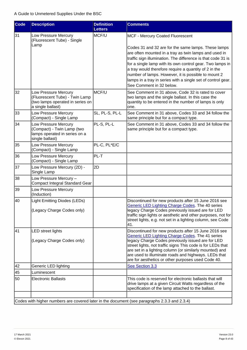
Code Description Definition Letters
Comments
31 Low Pressure Mercury (Fluorescent Tube) - Single Lamp
MCF/U MCF - Mercury Coated Fluorescent
Codes 31 and 32 are for the same lamps. These lamps
are often mounted in a tray as twin lamps and used in
traffic sign illumination. The difference is that code 31 is
for a single lamp with its own control gear. Two lamps in
a tray would therefore require a quantity of 2 in the
number of lamps. However, it is possible to mount 2
lamps in a tray in series with a single set of control gear.
See Comment in 32 below.
32 Low Pressure Mercury (Fluorescent Tube) - Twin Lamp (two lamps operated in series on a single ballast)
MCF/U See Comment in 31 above, Code 32 is rated to cover two lamps and the single ballast. In this case the quantity to be entered in the number of lamps is only one.
33 Low Pressure Mercury (Compact) - Single Lamp
SL, PL-S, PL-L See Comment in 31 above, Codes 33 and 34 follow the same principle but for a compact type.
34 Low Pressure Mercury (Compact) - Twin Lamp (two lamps operated in series on a single ballast)
PL-S, PL-L See Comment in 31 above, Codes 33 and 34 follow the same principle but for a compact type.
35 Low Pressure Mercury (Compact) - Single Lamp
PL-C, PL*E/C
36 Low Pressure Mercury (Compact) - Single Lamp
PL-T
37 Low Pressure Mercury (2D) - Single Lamp
2D
38 Low Pressure Mercury – Compact Integral Standard Gear
39 Low Pressure Mercury (Induction)
40 Light Emitting Diodes (LEDs) (Legacy Charge Codes only)
Discontinued for new products after 15 June 2016 see Generic LED Lighting Charge Codes. The 40 series legacy Charge Codes previously issued are for LED traffic sign lights or aesthetic and other purposes, not for street lights, e.g. not set in a lighting column, see Code 41.
41 LED street lights (Legacy Charge Codes only)
Discontinued for new products after 15 June 2016 see Generic LED Lighting Charge Codes. The 41 series legacy Charge Codes previously issued are for LED street lights, not traffic signs This code is for LEDs that are set in a lighting column (or similarly mounted) and are used to illuminate roads and highways. LEDs that are for aesthetics or other purposes used Code 40.
42 Generic LED lighting See Section 3.3
45 Luminescent
50 Electronic Ballasts This code is reserved for electronic ballasts that will drive lamps at a given Circuit Watts regardless of the specification of the lamp attached to the ballast.
Codes with higher numbers are covered later in the document (see paragraphs 2.3.3 and 2.3.4)
A Guide to Unmetered Supplies Under the BSC
17 March 2021 Version 23.0
© Elexon 2021 Page 9 of 43
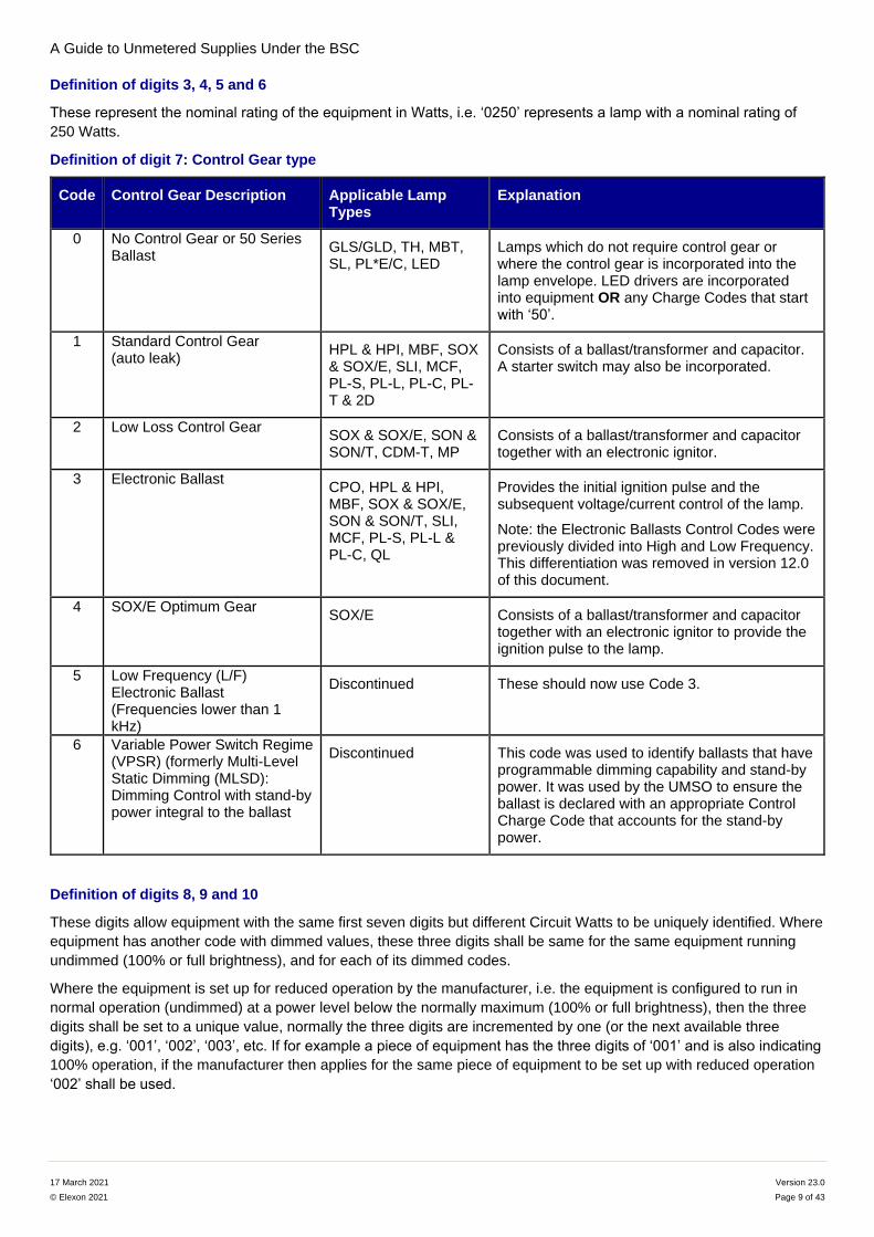
Definition of digits 3, 4, 5 and 6
These represent the nominal rating of the equipment in Watts, i.e. ‘0250’ represents a lamp with a nominal rating of
250 Watts.
Definition of digit 7: Control Gear type
Code Control Gear Description Applicable Lamp Types
Explanation
0 No Control Gear or 50 Series Ballast
GLS/GLD, TH, MBT, SL, PL*E/C, LED
Lamps which do not require control gear or where the control gear is incorporated into the lamp envelope. LED drivers are incorporated into equipment OR any Charge Codes that start with ‘50’.
1 Standard Control Gear (auto leak)
HPL & HPI, MBF, SOX & SOX/E, SLI, MCF, PL-S, PL-L, PL-C, PL-T & 2D
Consists of a ballast/transformer and capacitor. A starter switch may also be incorporated.
2 Low Loss Control Gear SOX & SOX/E, SON & SON/T, CDM-T, MP
Consists of a ballast/transformer and capacitor together with an electronic ignitor.
3 Electronic Ballast CPO, HPL & HPI, MBF, SOX & SOX/E, SON & SON/T, SLI, MCF, PL-S, PL-L & PL-C, QL
Provides the initial ignition pulse and the subsequent voltage/current control of the lamp.
Note: the Electronic Ballasts Control Codes were previously divided into High and Low Frequency. This differentiation was removed in version 12.0 of this document.
4 SOX/E Optimum Gear SOX/E Consists of a ballast/transformer and capacitor
together with an electronic ignitor to provide the ignition pulse to the lamp.
5 Low Frequency (L/F) Electronic Ballast (Frequencies lower than 1 kHz)
Discontinued These should now use Code 3.
6 Variable Power Switch Regime (VPSR) (formerly Multi-Level Static Dimming (MLSD): Dimming Control with stand-by power integral to the ballast
Discontinued This code was used to identify ballasts that have programmable dimming capability and stand-by power. It was used by the UMSO to ensure the ballast is declared with an appropriate Control Charge Code that accounts for the stand-by power.
Definition of digits 8, 9 and 10
These digits allow equipment with the same first seven digits but different Circuit Watts to be uniquely identified. Where
equipment has another code with dimmed values, these three digits shall be same for the same equipment running
undimmed (100% or full brightness), and for each of its dimmed codes.
Where the equipment is set up for reduced operation by the manufacturer, i.e. the equipment is configured to run in
normal operation (undimmed) at a power level below the normally maximum (100% or full brightness), then the three
digits shall be set to a unique value, normally the three digits are incremented by one (or the next available three
digits), e.g. ‘001’, ‘002’, ‘003’, etc. If for example a piece of equipment has the three digits of ‘001’ and is also indicating
100% operation, if the manufacturer then applies for the same piece of equipment to be set up with reduced operation
‘002’ shall be used.
A Guide to Unmetered Supplies Under the BSC
17 March 2021 Version 23.0
© Elexon 2021 Page 10 of 43
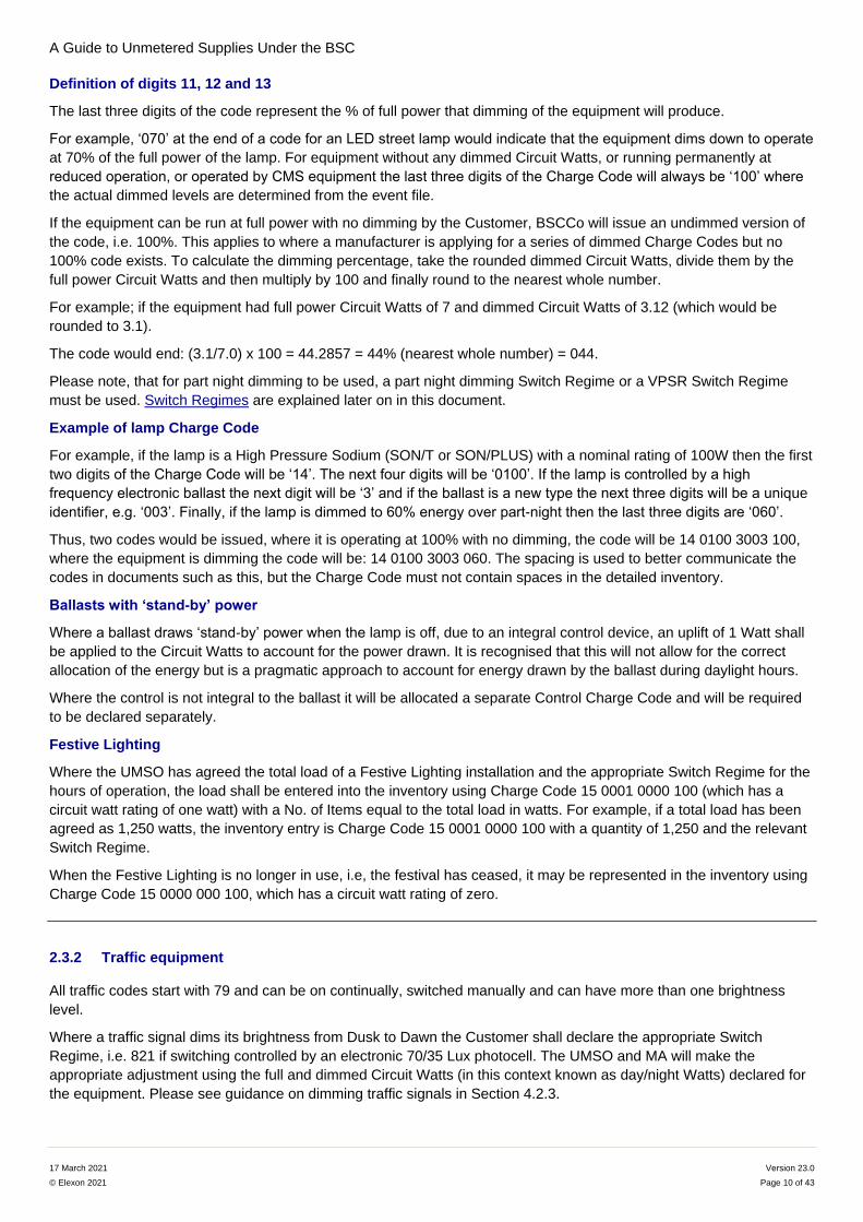
Definition of digits 11, 12 and 13
The last three digits of the code represent the % of full power that dimming of the equipment will produce.
For example, ‘070’ at the end of a code for an LED street lamp would indicate that the equipment dims down to operate
at 70% of the full power of the lamp. For equipment without any dimmed Circuit Watts, or running permanently at
reduced operation, or operated by CMS equipment the last three digits of the Charge Code will always be ‘100’ where
the actual dimmed levels are determined from the event file.
If the equipment can be run at full power with no dimming by the Customer, BSCCo will issue an undimmed version of
the code, i.e. 100%. This applies to where a manufacturer is applying for a series of dimmed Charge Codes but no
100% code exists. To calculate the dimming percentage, take the rounded dimmed Circuit Watts, divide them by the
full power Circuit Watts and then multiply by 100 and finally round to the nearest whole number.
For example; if the equipment had full power Circuit Watts of 7 and dimmed Circuit Watts of 3.12 (which would be
rounded to 3.1).
The code would end: (3.1/7.0) x 100 = 44.2857 = 44% (nearest whole number) = 044.
Please note, that for part night dimming to be used, a part night dimming Switch Regime or a VPSR Switch Regime
must be used. Switch Regimes are explained later on in this document.
Example of lamp Charge Code
For example, if the lamp is a High Pressure Sodium (SON/T or SON/PLUS) with a nominal rating of 100W then the first
two digits of the Charge Code will be ‘14’. The next four digits will be ‘0100’. If the lamp is controlled by a high
frequency electronic ballast the next digit will be ‘3’ and if the ballast is a new type the next three digits will be a unique
identifier, e.g. ‘003’. Finally, if the lamp is dimmed to 60% energy over part-night then the last three digits are ‘060’.
Thus, two codes would be issued, where it is operating at 100% with no dimming, the code will be 14 0100 3003 100,
where the equipment is dimming the code will be: 14 0100 3003 060. The spacing is used to better communicate the
codes in documents such as this, but the Charge Code must not contain spaces in the detailed inventory.
Ballasts with ‘stand-by’ power
Where a ballast draws ‘stand-by’ power when the lamp is off, due to an integral control device, an uplift of 1 Watt shall
be applied to the Circuit Watts to account for the power drawn. It is recognised that this will not allow for the correct
allocation of the energy but is a pragmatic approach to account for energy drawn by the ballast during daylight hours.
Where the control is not integral to the ballast it will be allocated a separate Control Charge Code and will be required
to be declared separately.
Festive Lighting
Where the UMSO has agreed the total load of a Festive Lighting installation and the appropriate Switch Regime for the
hours of operation, the load shall be entered into the inventory using Charge Code 15 0001 0000 100 (which has a
circuit watt rating of one watt) with a No. of Items equal to the total load in watts. For example, if a total load has been
agreed as 1,250 watts, the inventory entry is Charge Code 15 0001 0000 100 with a quantity of 1,250 and the relevant
Switch Regime.
When the Festive Lighting is no longer in use, i.e, the festival has ceased, it may be represented in the inventory using
Charge Code 15 0000 000 100, which has a circuit watt rating of zero.
2.3.2 Traffic equipment
All traffic codes start with 79 and can be on continually, switched manually and can have more than one brightness
level.
Where a traffic signal dims its brightness from Dusk to Dawn the Customer shall declare the appropriate Switch
Regime, i.e. 821 if switching controlled by an electronic 70/35 Lux photocell. The UMSO and MA will make the
appropriate adjustment using the full and dimmed Circuit Watts (in this context known as day/night Watts) declared for
the equipment. Please see guidance on dimming traffic signals in Section 4.2.3.

A Guide to Unmetered Supplies Under the BSC
17 March 2021 Version 23.0
© Elexon 2021 Page 11 of 43
Digits Description
1 and 2 Always 79. Traffic signal codes begin with “79” as the first two digits.
3 and 4 Numeric code that represents the type of traffic signal equipment
5, 6 and 7 The nominal Watts (not the same as Circuit Watts)
8, 9 and 10 A numeric code that allows equipment with the same first seven digits of the Charge Code but with different Circuit Watts to be uniquely identified.
11, 12 and 13 Always ‘100’. It should be noted that traffic lights and other non-lighting traffic equipment may have ‘day’ and ‘night’ Watts. This means that there is no need for a fixed dimming percentage at the end of the code because dimming percentages apply to part night dimming in conjunction with part night switching regimes. For a fuller explanation see paragraph 4.2.3.
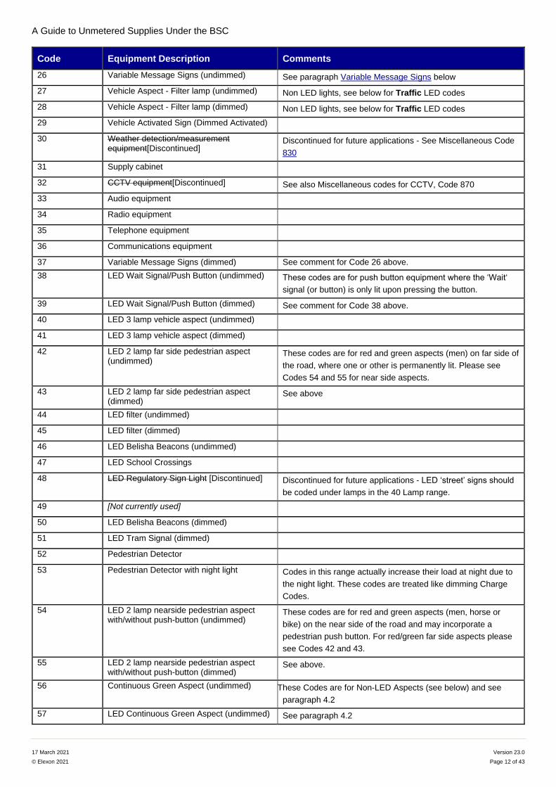
Definition of digits 3 and 4:
Code Equipment Description Comments
01 Incandescent 3 lamp vehicle aspect
(undimmed)
Non LED lights, see below for Traffic LED codes
02 Incandescent 3 lamp vehicle aspect
(dimmed)
Non LED lights, see below for Traffic LED codes
03 Incandescent 2 lamp pedestrian aspect
(undimmed)
Non LED lights, see below for Traffic LED codes
These codes are for red and green aspects (men), where one
or other is permanently lit.
04 Incandescent 2 lamp pedestrian aspect
(dimmed)
Non LED lights, see below for Traffic LED codes
05 Incandescent Wait Signal/Push Button
(undimmed)
Non LED lights, see below for Traffic LED codes
06 Controller
07 Vehicle Detector
08 Cableless Link Unit (CLU)
09 Lamp Monitoring Unit (LMU)
10 Outstation Monitoring Unit (OMU)
11 Outstation Transmission Unit (OTU)
12 Detector Power Pack Unit (DPU)
13 Speed Discrimination Unit (SDU)
14 Variable Maximum Unit (VMU)
15 Microprocessor Optimised Vehicle
Actuation (MOVA)
16 Incandescent Belisha Beacons Non LED lights, see below for Traffic LED codes
17 Regulatory or Box Sign Non LED lights, see below for Traffic LED codes
18 School Crossings
19 Pole Mounted Responder
20 Traffic Counter
21 Speeding/Red Light Camera
22 Motorway Overhead Gantry
23 Ticket Machine
24 Wait Signal/Push Button (dimmed)
25 Speed Warning Signs
A Guide to Unmetered Supplies Under the BSC
17 March 2021 Version 23.0
© Elexon 2021 Page 12 of 43
Code Equipment Description Comments
26 Variable Message Signs (undimmed) See paragraph Variable Message Signs below
27 Vehicle Aspect - Filter lamp (undimmed) Non LED lights, see below for Traffic LED codes
28 Vehicle Aspect - Filter lamp (dimmed) Non LED lights, see below for Traffic LED codes
29 Vehicle Activated Sign (Dimmed Activated)
30 Weather detection/measurement equipment[Discontinued]
Discontinued for future applications - See Miscellaneous Code
830
31 Supply cabinet
32 CCTV equipment[Discontinued] See also Miscellaneous codes for CCTV, Code 870
33 Audio equipment
34 Radio equipment
35 Telephone equipment
36 Communications equipment
37 Variable Message Signs (dimmed) See comment for Code 26 above.
38 LED Wait Signal/Push Button (undimmed) These codes are for push button equipment where the ‘Wait‘
signal (or button) is only lit upon pressing the button.
39 LED Wait Signal/Push Button (dimmed) See comment for Code 38 above.
40 LED 3 lamp vehicle aspect (undimmed)
41 LED 3 lamp vehicle aspect (dimmed)
42 LED 2 lamp far side pedestrian aspect (undimmed)
These codes are for red and green aspects (men) on far side of
the road, where one or other is permanently lit. Please see
Codes 54 and 55 for near side aspects.
43 LED 2 lamp far side pedestrian aspect (dimmed)
See above
44 LED filter (undimmed)
45 LED filter (dimmed)
46 LED Belisha Beacons (undimmed)
47 LED School Crossings
48 LED Regulatory Sign Light [Discontinued] Discontinued for future applications - LED ‘street’ signs should
be coded under lamps in the 40 Lamp range.
49 [Not currently used]
50 LED Belisha Beacons (dimmed)
51 LED Tram Signal (dimmed)
52 Pedestrian Detector
53 Pedestrian Detector with night light Codes in this range actually increase their load at night due to
the night light. These codes are treated like dimming Charge
Codes.
54 LED 2 lamp nearside pedestrian aspect with/without push-button (undimmed)
These codes are for red and green aspects (men, horse or
bike) on the near side of the road and may incorporate a
pedestrian push button. For red/green far side aspects please
see Codes 42 and 43.
55 LED 2 lamp nearside pedestrian aspect with/without push-button (dimmed)
See above.
56 Continuous Green Aspect (undimmed) These Codes are for Non-LED Aspects (see below) and see
paragraph 4.2
57 LED Continuous Green Aspect (undimmed) See paragraph 4.2
A Guide to Unmetered Supplies Under the BSC
17 March 2021 Version 23.0
© Elexon 2021 Page 13 of 43
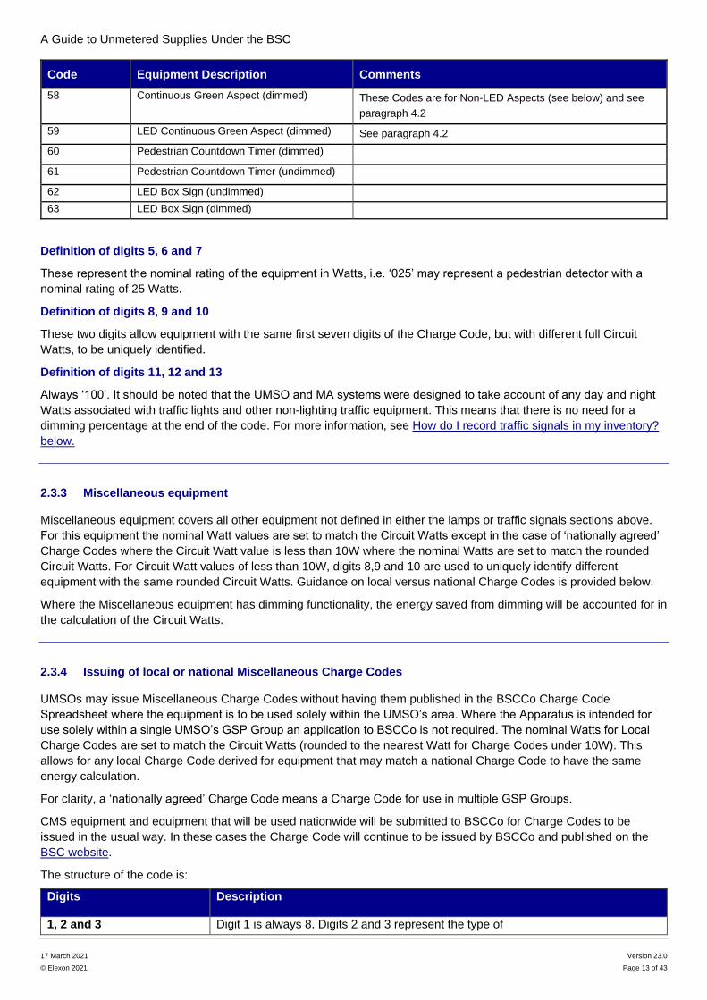
Code Equipment Description Comments
58 Continuous Green Aspect (dimmed) These Codes are for Non-LED Aspects (see below) and see
paragraph 4.2
59 LED Continuous Green Aspect (dimmed) See paragraph 4.2
60 Pedestrian Countdown Timer (dimmed)
61 Pedestrian Countdown Timer (undimmed)
62 LED Box Sign (undimmed)
63 LED Box Sign (dimmed)
Definition of digits 5, 6 and 7
These represent the nominal rating of the equipment in Watts, i.e. ‘025’ may represent a pedestrian detector with a
nominal rating of 25 Watts.
Definition of digits 8, 9 and 10
These two digits allow equipment with the same first seven digits of the Charge Code, but with different full Circuit
Watts, to be uniquely identified.
Definition of digits 11, 12 and 13
Always ‘100’. It should be noted that the UMSO and MA systems were designed to take account of any day and night
Watts associated with traffic lights and other non-lighting traffic equipment. This means that there is no need for a
dimming percentage at the end of the code. For more information, see How do I record traffic signals in my inventory?
below.
2.3.3 Miscellaneous equipment
Miscellaneous equipment covers all other equipment not defined in either the lamps or traffic signals sections above.
For this equipment the nominal Watt values are set to match the Circuit Watts except in the case of ‘nationally agreed’
Charge Codes where the Circuit Watt value is less than 10W where the nominal Watts are set to match the rounded
Circuit Watts. For Circuit Watt values of less than 10W, digits 8,9 and 10 are used to uniquely identify different
equipment with the same rounded Circuit Watts. Guidance on local versus national Charge Codes is provided below.
Where the Miscellaneous equipment has dimming functionality, the energy saved from dimming will be accounted for in
the calculation of the Circuit Watts.
2.3.4 Issuing of local or national Miscellaneous Charge Codes
UMSOs may issue Miscellaneous Charge Codes without having them published in the BSCCo Charge Code
Spreadsheet where the equipment is to be used solely within the UMSO’s area. Where the Apparatus is intended for
use solely within a single UMSO’s GSP Group an application to BSCCo is not required. The nominal Watts for Local
Charge Codes are set to match the Circuit Watts (rounded to the nearest Watt for Charge Codes under 10W). This
allows for any local Charge Code derived for equipment that may match a national Charge Code to have the same
energy calculation.
For clarity, a ‘nationally agreed’ Charge Code means a Charge Code for use in multiple GSP Groups.
CMS equipment and equipment that will be used nationwide will be submitted to BSCCo for Charge Codes to be
issued in the usual way. In these cases the Charge Code will continue to be issued by BSCCo and published on the
BSC website.
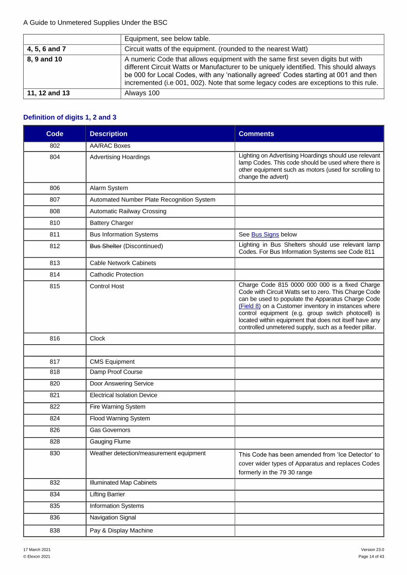
The structure of the code is:
Digits Description
1, 2 and 3 Digit 1 is always 8. Digits 2 and 3 represent the type of
A Guide to Unmetered Supplies Under the BSC
17 March 2021 Version 23.0
© Elexon 2021 Page 14 of 43
Equipment, see below table.
4, 5, 6 and 7 Circuit watts of the equipment. (rounded to the nearest Watt)
8, 9 and 10 A numeric Code that allows equipment with the same first seven digits but with different Circuit Watts or Manufacturer to be uniquely identified. This should always be 000 for Local Codes, with any ‘nationally agreed’ Codes starting at 001 and then incremented (i.e 001, 002). Note that some legacy codes are exceptions to this rule.
11, 12 and 13 Always 100
Definition of digits 1, 2 and 3
Code Description Comments
802 AA/RAC Boxes
804 Advertising Hoardings Lighting on Advertising Hoardings should use relevant lamp Codes. This code should be used where there is other equipment such as motors (used for scrolling to change the advert)
806 Alarm System
807 Automated Number Plate Recognition System
808 Automatic Railway Crossing
810 Battery Charger
811 Bus Information Systems See Bus Signs below
812 Bus Shelter (Discontinued) Lighting in Bus Shelters should use relevant lamp Codes. For Bus Information Systems see Code 811
813 Cable Network Cabinets
814 Cathodic Protection
815 Control Host Charge Code 815 0000 000 000 is a fixed Charge Code with Circuit Watts set to zero. This Charge Code can be used to populate the Apparatus Charge Code (Field 8) on a Customer inventory in instances where control equipment (e.g. group switch photocell) is located within equipment that does not itself have any controlled unmetered supply, such as a feeder pillar.
816 Clock
817 CMS Equipment
818 Damp Proof Course
820 Door Answering Service
821 Electrical Isolation Device
822 Fire Warning System
824 Flood Warning System
826 Gas Governors
828 Gauging Flume
830 Weather detection/measurement equipment This Code has been amended from ‘Ice Detector’ to
cover wider types of Apparatus and replaces Codes
formerly in the 79 30 range
832 Illuminated Map Cabinets
834 Lifting Barrier
835 Information Systems
836 Navigation Signal
838 Pay & Display Machine
A Guide to Unmetered Supplies Under the BSC
17 March 2021 Version 23.0
© Elexon 2021 Page 15 of 43
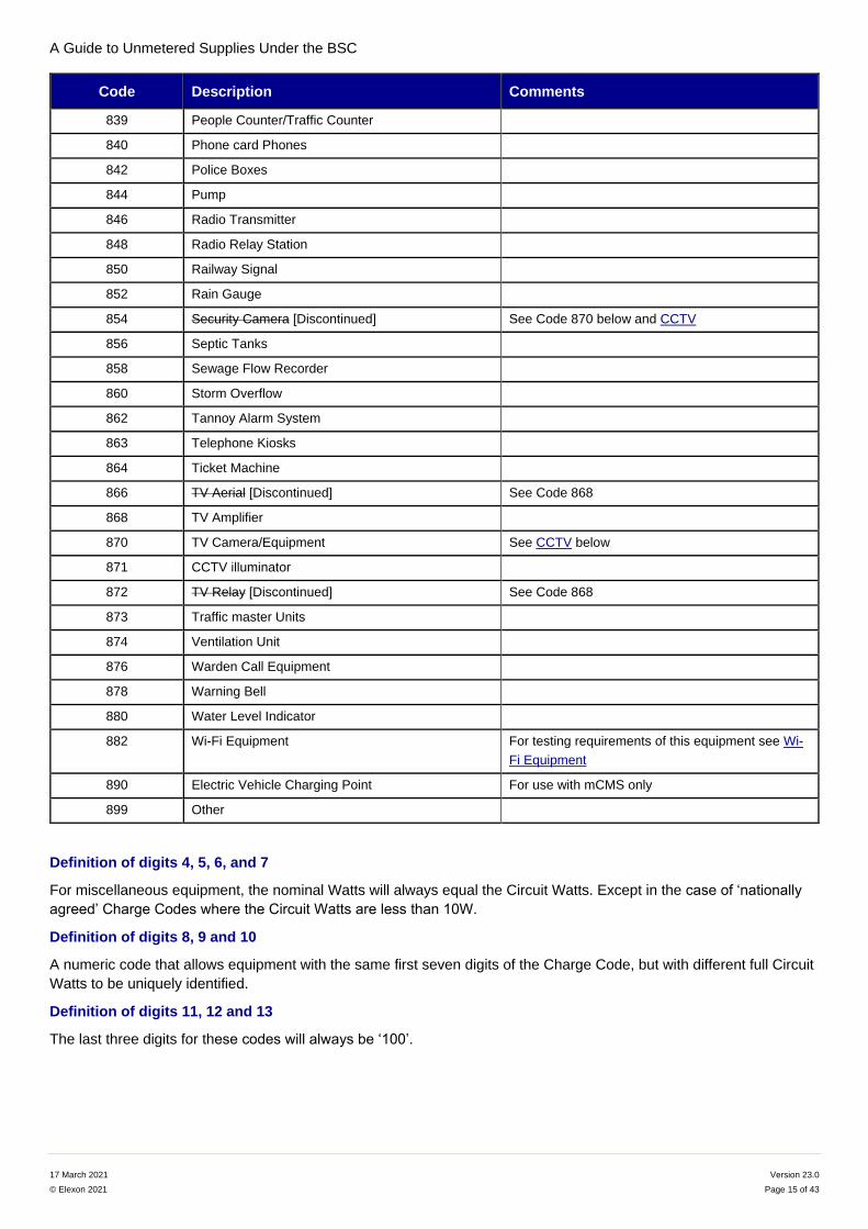
Code Description Comments
839 People Counter/Traffic Counter
840 Phone card Phones
842 Police Boxes
844 Pump
846 Radio Transmitter
848 Radio Relay Station
850 Railway Signal
852 Rain Gauge
854 Security Camera [Discontinued] See Code 870 below and CCTV
856 Septic Tanks
858 Sewage Flow Recorder
860 Storm Overflow
862 Tannoy Alarm System
863 Telephone Kiosks
864 Ticket Machine
866 TV Aerial [Discontinued] See Code 868
868 TV Amplifier
870 TV Camera/Equipment See CCTV below
871 CCTV illuminator
872 TV Relay [Discontinued] See Code 868
873 Traffic master Units
874 Ventilation Unit
876 Warden Call Equipment
878 Warning Bell
880 Water Level Indicator
882 Wi-Fi Equipment For testing requirements of this equipment see Wi-
Fi Equipment
890 Electric Vehicle Charging Point For use with mCMS only
899 Other
Definition of digits 4, 5, 6, and 7
For miscellaneous equipment, the nominal Watts will always equal the Circuit Watts. Except in the case of ‘nationally
agreed’ Charge Codes where the Circuit Watts are less than 10W.
Definition of digits 8, 9 and 10
A numeric code that allows equipment with the same first seven digits of the Charge Code, but with different full Circuit
Watts to be uniquely identified.
Definition of digits 11, 12 and 13
The last three digits for these codes will always be ‘100’.
A Guide to Unmetered Supplies Under the BSC
17 March 2021 Version 23.0
© Elexon 2021 Page 16 of 43
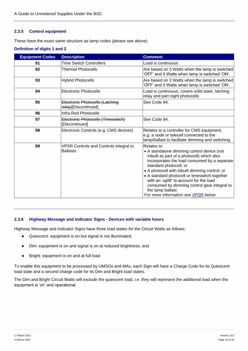
2.3.5 Control equipment
These have the exact same structure as lamp codes (please see above)
Definition of digits 1 and 2
Equipment Codes Description Comment
91 Time Switch Controllers Load is continuous
92 Thermal Photocells Are based on 3 Watts when the lamp is switched ‘OFF’ and 0 Watts when lamp is switched ‘ON’.
93 Hybrid Photocells Are based on 3 Watts when the lamp is switched ‘OFF’ and 0 Watts when lamp is switched ‘ON’.
94 Electronic Photocells Load is continuous, covers solid state, latching relay and part night photocells
95 Electronic Photocells (Latching relay)[Discontinued]
See Code 94.
96 Infra-Red Photocells
97 Electronic Photocells (Timeswitch) [Discontinued]
See Code 94.
98 Electronic Controls (e.g. CMS devices) Relates to a controller for CMS equipment. e.g. a node or telecell connected to the lamp/ballast to facilitate dimming and switching.
99 VPSR Controls and Controls integral to Ballasts
Relates to:
A standalone dimming control device (not inbuilt as part of a photocell) which also incorporates the load consumed by a separate standard photocell; or
A photocell with inbuilt dimming control; or
A standard photocell or timeswitch together with an ‘uplift’ to account for the load consumed by dimming control gear integral to the lamp ballast.
For more information see VPSR below
2.3.6 Highway Message and Indicator Signs - Devices with variable hours
Highway Message and Indicator Signs have three load states for the Circuit Watts as follows:
Quiescent: equipment is on but signal is not illuminated;
Dim: equipment is on and signal is on at reduced brightness; and
Bright: equipment is on and at full load.
To enable this equipment to be processed by UMSOs and MAs, each Sign will have a Charge Code for its Quiescent
load state and a second charge code for its Dim and Bright load states.
The Dim and Bright Circuit Watts will exclude the quiescent load, i.e. they will represent the additional load when the
equipment is ‘on’ and operational.
A Guide to Unmetered Supplies Under the BSC
17 March 2021 Version 23.0
© Elexon 2021 Page 17 of 43
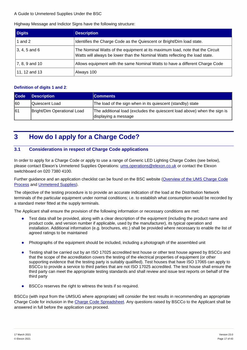
Highway Message and Indictor Signs have the following structure:
Digits Description
1 and 2 Identifies the Charge Code as the Quiescent or Bright/Dim load state.
3, 4, 5 and 6 The Nominal Watts of the equipment at its maximum load, note that the Circuit
Watts will always be lower than the Nominal Watts reflecting the load state.
7, 8, 9 and 10 Allows equipment with the same Nominal Watts to have a different Charge Code
11, 12 and 13 Always 100
Definition of digits 1 and 2:
Code Description Comments
60 Quiescent Load The load of the sign when in its quiescent (standby) state
61 Bright/Dim Operational Load The additional load (excludes the quiescent load above) when the sign is
displaying a message
3 How do I apply for a Charge Code?
3.1 Considerations in respect of Charge Code applications
In order to apply for a Charge Code or apply to use a range of Generic LED Lighting Charge Codes (see below),
please contact Elexon’s Unmetered Supplies Operations: [email protected] or contact the Elexon
switchboard on 020 7380 4100.
Further guidance and an application checklist can be found on the BSC website (Overview of the UMS Charge Code
Process and Unmetered Supplies).
The objective of the testing procedure is to provide an accurate indication of the load at the Distribution Network
terminals of the particular equipment under normal conditions; i.e. to establish what consumption would be recorded by
a standard meter fitted at the supply terminals.
The Applicant shall ensure the provision of the following information or necessary conditions are met:
Test data shall be provided, along with a clear description of the equipment (including the product name and product code, and version number if applicable, used by the manufacturer), its typical operation and installation. Additional information (e.g. brochures, etc.) shall be provided where necessary to enable the list of agreed ratings to be maintained
Photographs of the equipment should be included, including a photograph of the assembled unit
Testing shall be carried out by an ISO 17025 accredited test house or other test house agreed by BSCCo and that the scope of the accreditation covers the testing of the electrical properties of equipment (or other supporting evidence that the testing party is suitably qualified). Test houses that have ISO 17065 can apply to BSCCo to provide a service to third parties that are not ISO 17025 accredited. The test house shall ensure the third party can meet the appropriate testing standards and shall review and issue test reports on behalf of the third party
BSCCo reserves the right to witness the tests if so required.
BSCCo (with input from the UMSUG where appropriate) will consider the test results in recommending an appropriate
Charge Code for inclusion in the Charge Code Spreadsheet. Any questions raised by BSCCo to the Applicant shall be
answered in full before the application can proceed.
A Guide to Unmetered Supplies Under the BSC
17 March 2021 Version 23.0
© Elexon 2021 Page 18 of 43
3.2 Test data requirements
The Applicant shall adhere to the following requirements when preparing the test data:
Both power/voltage and volt-ampere/voltage curves will be required with measurements taken at 210, 220, 230, 240 and 250 volts, 50 hertz. Typically, the power measurements provided shall be greater or equal to the nominal Watts stated in the Charge Code application
The accuracy of the measurements shall be stated and the minimum accuracy shall be ±2% of the recorded value as per the Electricity (Unmetered Supply) Regulations 2001
The testing set-up to undertake the power measurements shall include any voltage transformers, drivers or any other equipment necessary to operate the equipment from the mains. If there are multiple pieces of equipment (each requiring a separate Charge Code) being supplied by one transformer or power supply unit, the power measurements shall exclude that transformer or power supply unit. Please note that an uplift of 10% will be added to the power measurements in deriving the circuit (and/or dimming) watts
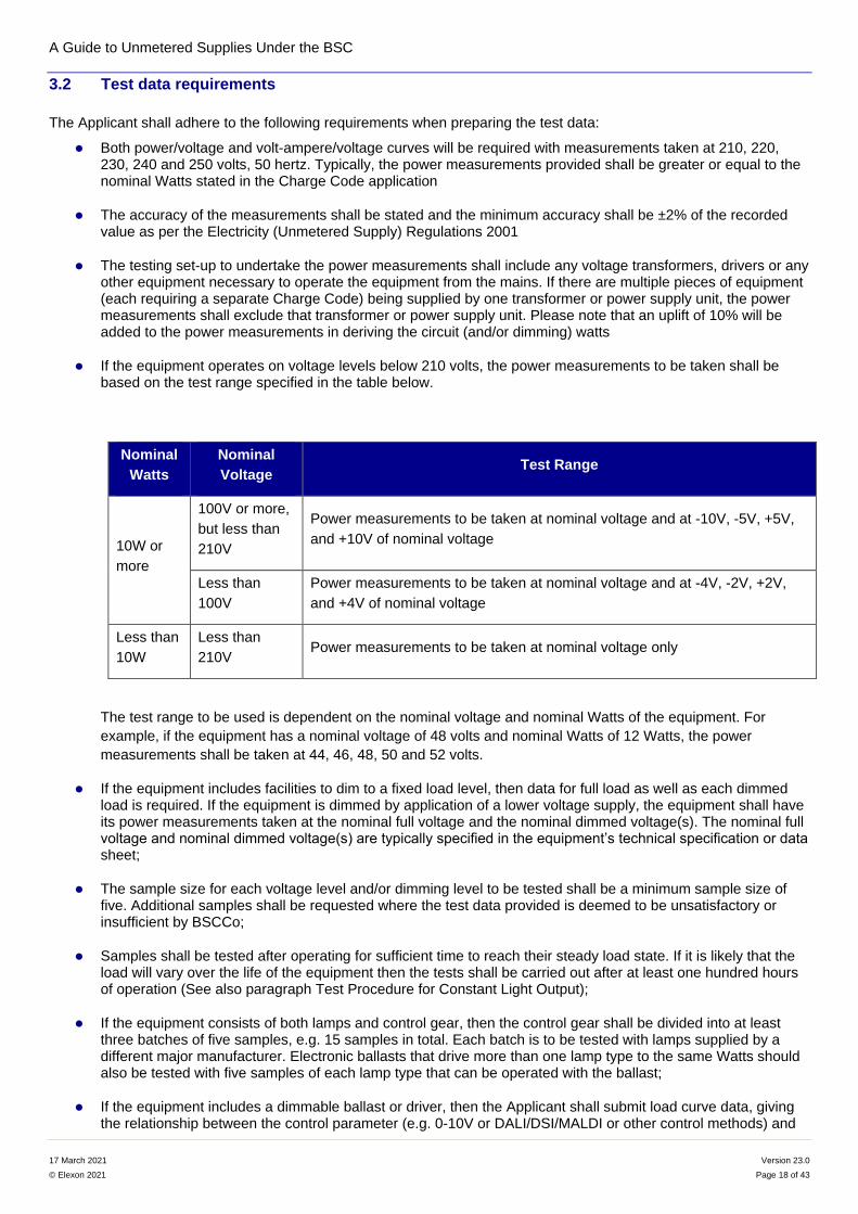
If the equipment operates on voltage levels below 210 volts, the power measurements to be taken shall be based on the test range specified in the table below.
Nominal
Watts
Nominal
Voltage Test Range
10W or
more
100V or more,
but less than
210V
Power measurements to be taken at nominal voltage and at -10V, -5V, +5V,
and +10V of nominal voltage
Less than
100V
Power measurements to be taken at nominal voltage and at -4V, -2V, +2V,
and +4V of nominal voltage
Less than
10W
Less than
210V Power measurements to be taken at nominal voltage only
The test range to be used is dependent on the nominal voltage and nominal Watts of the equipment. For
example, if the equipment has a nominal voltage of 48 volts and nominal Watts of 12 Watts, the power
measurements shall be taken at 44, 46, 48, 50 and 52 volts.
If the equipment includes facilities to dim to a fixed load level, then data for full load as well as each dimmed load is required. If the equipment is dimmed by application of a lower voltage supply, the equipment shall have its power measurements taken at the nominal full voltage and the nominal dimmed voltage(s). The nominal full voltage and nominal dimmed voltage(s) are typically specified in the equipment’s technical specification or data sheet;
The sample size for each voltage level and/or dimming level to be tested shall be a minimum sample size of five. Additional samples shall be requested where the test data provided is deemed to be unsatisfactory or insufficient by BSCCo;
Samples shall be tested after operating for sufficient time to reach their steady load state. If it is likely that the load will vary over the life of the equipment then the tests shall be carried out after at least one hundred hours of operation (See also paragraph Test Procedure for Constant Light Output);
If the equipment consists of both lamps and control gear, then the control gear shall be divided into at least three batches of five samples, e.g. 15 samples in total. Each batch is to be tested with lamps supplied by a different major manufacturer. Electronic ballasts that drive more than one lamp type to the same Watts should also be tested with five samples of each lamp type that can be operated with the ballast;
If the equipment includes a dimmable ballast or driver, then the Applicant shall submit load curve data, giving the relationship between the control parameter (e.g. 0-10V or DALI/DSI/MALDI or other control methods) and
A Guide to Unmetered Supplies Under the BSC
17 March 2021 Version 23.0
© Elexon 2021 Page 19 of 43
the power input to the equipment. Additionally, the maximum and minimum level to which these ballasts or drivers can operate shall be provided with the Charge Code application;
If the equipment is housed within a cabinet, then clear evidence shall be provided that additional equipment cannot be added (e.g. not scalable) and that a meter cannot be installed or that it fits the criteria for an unmetered supply as defined in the Unmetered Supply Statutory Instrument (2001 No. 3263);
If the equipment incorporates heating (e.g. frost heaters) or cooling equipment (e.g. fans) then the estimated operating hours under the different regimes should be reported;
If the equipment load varies with ambient temperature then test data shall be provided at a room temperature (approx. 20ºC). The testing temperature shall be declared and a statement or data shall be provided on the maximum variation in load at both likely extremes (high and low) with the application;
It is historically a standard requirement of UMS Connection Agreements or the National Terms of Connection that the power factor of connected equipment shall be as near to unity as practicable but in any case not less than 0.85 lagging or 0.95 leading. If the equipment does not meet this standard then a Distribution Business may refuse to connect the equipment. Where an application is made for a piece of equipment with a Circuit Watts of less than 25 Watts then lower power factors will normally be considered;
The test house should identify whether the power factor is leading or lagging and this information should be provided by the Applicant. Leading power factors will be declared as neutral/unity in the Charge Code Spreadsheet.
3.3 Applying to use a range of Generic LED Lighting Charge Codes
From 15 June 2016 LED manufacturers or Customers can apply to use these Charge Codes by either providing:
data showing the power range of the driver settings that can be used; and
a load curve based on test data from sufficient different dimming levels (to include full power and the minimum dimming level); or
details of legacy LED products to be mapped to generic Charge Codes (test results not required).
This allows us to extrapolate intermediate power levels. We still expect the test data to include both Watts (W) and Volt
Amps (VA). We are assuming a unity power factor of 1 for the purposes of the generic Charge Codes. We shall provide
the manufacturer with confirmation that it can use all generic Charge Codes published on the Charge Code
Spreadsheet within the capability of the equipment (LED driver limits).
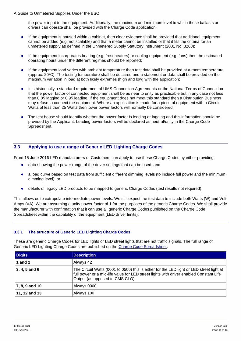
3.3.1 The structure of Generic LED Lighting Charge Codes
These are generic Charge Codes for LED lights or LED street lights that are not traffic signals. The full range of
Generic LED Lighting Charge Codes are published on the Charge Code Spreadsheet.
Digits Description
1 and 2 Always 42
3, 4, 5 and 6 The Circuit Watts (0001 to 0500) this is either for the LED light or LED street light at full power or a mid-life value for LED street lights with driver enabled Constant Life Output (as opposed to CMS CLO)
7, 8, 9 and 10 Always 0000
11, 12 and 13 Always 100
A Guide to Unmetered Supplies Under the BSC
17 March 2021 Version 23.0
© Elexon 2021 Page 20 of 43
Definition of digits 1 and 2
The value of 42 defines the product as an LED light or an LED street light.
Definition of digits 3, 4, 5 and 6
These represent the Circuit Watts of the equipment in Watts at full power, i.e. ‘0250’ represents a lamp with a full
power rating of 250 Watts. For lamps with driver enabled CLO this will be the mid-life value.
Definition of digits 7, 8, 9 and 10
The value of 0000 defines the product as a Generic LED light or a Generic LED street light.
Definition of digits 11, 12 and 13
The value of 100 defines that these Charge Codes are the full power rating for the lamp. Dimming of these Generic
LED Lighting Charge Codes is achieved by linking them with a dimming Switch Regime which is explained later in this
document.
3.3.2 Manufacturer Equipment LED Range Spreadsheet
We will publish each manufacturer’s allowed Charge Code range for each product/drivers range on the Manufacturer
Equipment LED Range Spreadsheet on the BSC website . As a minimum the spreadsheet will include:
the manufacturer;
the manufacturer’s product designation;
the Generic LED Lighting Charge Codes – lower limit; and
the Generic LED Lighting Charge Codes – upper limit.
For applications to use a range of Generic LED Lighting Charge Codes the successful Applicant will be informed that it
can use the appropriate range. The Apparatus and valid range will be included in the Manufacturer Equipment LED
Range Spreadsheet.
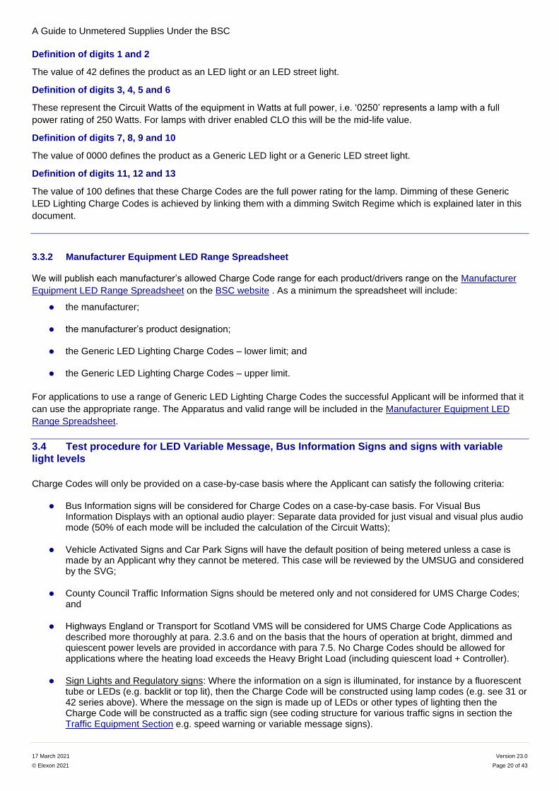
3.4 Test procedure for LED Variable Message, Bus Information Signs and signs with variable
light levels
Charge Codes will only be provided on a case-by-case basis where the Applicant can satisfy the following criteria:
Bus Information signs will be considered for Charge Codes on a case-by-case basis. For Visual Bus Information Displays with an optional audio player: Separate data provided for just visual and visual plus audio mode (50% of each mode will be included the calculation of the Circuit Watts);
Vehicle Activated Signs and Car Park Signs will have the default position of being metered unless a case is made by an Applicant why they cannot be metered. This case will be reviewed by the UMSUG and considered by the SVG;
County Council Traffic Information Signs should be metered only and not considered for UMS Charge Codes; and
Highways England or Transport for Scotland VMS will be considered for UMS Charge Code Applications as described more thoroughly at para. 2.3.6 and on the basis that the hours of operation at bright, dimmed and quiescent power levels are provided in accordance with para 7.5. No Charge Codes should be allowed for applications where the heating load exceeds the Heavy Bright Load (including quiescent load + Controller).
Sign Lights and Regulatory signs: Where the information on a sign is illuminated, for instance by a fluorescent tube or LEDs (e.g. backlit or top lit), then the Charge Code will be constructed using lamp codes (e.g. see 31 or 42 series above). Where the message on the sign is made up of LEDs or other types of lighting then the Charge Code will be constructed as a traffic sign (see coding structure for various traffic signs in section the Traffic Equipment Section e.g. speed warning or variable message signs).
A Guide to Unmetered Supplies Under the BSC
17 March 2021 Version 23.0
© Elexon 2021 Page 21 of 43
Where applications are agreed the test data shall be provided along with a description of typical operation and
installation of the equipment. Application for Charge Codes shall be made on a per unit basis, e.g. one Charge Code to
include all items such as the controller, heating elements, and the message block sign. The message blocks shall be
tested with either ‘BBBB’ or ‘8888’ illuminated for the full width of the block. Where a message sign can be dimmed test
data shall be provided on the same basis as for full load with the sign dimmed.
The Applicant shall provide clear detail on why the load is deemed to be predictable and why the equipment cannot, or
is impractical for it to, be metered.
This equipment is deemed to be on continuously. There should be one Charge Code which includes an agreed
percentage for all of the elements making up the full installation, such as heater, controller, etc. It will be necessary to
determine an average load for the display, taking into consideration any night time dimming (see paragraph 3.2).
The equipment shall then be tested in line with the testing requirements described in the section above. Where Charge
Codes can be provided for Vehicle Activated Speed Warning Signs the Circuit Watts will be derived using the
quiescent load of the unlit sign with an uplift equal to 10% of the load of the sign when illuminated. Test data for both
modes of operation must therefore be provided by the Applicant.
Where Apparatus (other than street lights) has variable light levels the BSCCo will apply a weight to the load at each
light level according to the percentage of time that the Apparatus is deemed to be at each light level. The Applicant
must provide sufficient detail on the operation of the Apparatus to allow BSCCo to determine the appropriate
weightings.
BSCCo will consider the test information provided and consult with the Customer as to an appropriate figure for the
Circuit Watts.
3.5 Test procedure for Belisha Beacons
Belisha Beacons shall be tested at a constant load with the lamp constantly on (i.e. no flashing). BSCCo will then take
62% of the full Circuit Watts to account for the lamp flashing. Alternatively, the energy consumed over the period of say
10 minutes will give the average consumption while flashing. When submitting test evidence, the method of test should
be clearly stated.
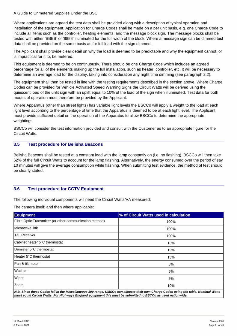
3.6 Test procedure for CCTV Equipment
The following individual components will need the Circuit Watts/VA measured:
The camera itself; and then where applicable:
Equipment % of Circuit Watts used in calculation
Fibre Optic Transmitter (or other communication method) 100%
Microwave link 100%
Tel. Receiver 100%
Cabinet heater 5°C thermostat 13%
Demister 5°C thermostat 13%
Heater 5°C thermostat 13%
Pan & tilt motor 5%
Washer 5%
Wiper 5%
Zoom 10%
N.B. Since these Codes fall in the Miscellaneous 800 range, UMSOs can allocate their own Charge Codes using the table. Nominal Watts must equal Circuit Watts. For Highways England equipment this must be submitted to BSCCo as used nationwide.
A Guide to Unmetered Supplies Under the BSC
17 March 2021 Version 23.0
© Elexon 2021 Page 22 of 43
The camera, which is the core component, shall be tested at five voltages and with a minimum of five samples. All
other additional components, as detailed in the table above, shall be tested at one sample each and at one voltage.
Alternatively, where it is impracticable to disassemble the CCTV equipment and test each component separately, the
whole equipment shall be tested at different operating modes. Please see below for an example:
Example
Suppose a CCTV equipment is made up of these components: Camera, Heater, Wiper, Pan & tilt motor, and Zoom.
The whole equipment shall be tested at the following modes:
Mode 1: Only the Camera itself in operation, with all other components switched off
Mode 2: Camera and Heater in operation
Mode 3: Camera and Wiper in operation
Mode 4: Panning and tilting the Camera at full speed
Mode 5: Zooming the Camera at full speed
BSCCo will compare the test data from Mode 1 against all other operating modes to derive the energy consumption of
each additional component. For example, to derive the energy consumption of the Heater itself, BSCCo will calculate
the difference using the test results from Mode 1 and Mode 2.
Applicants shall test the camera, under Mode 1, at five voltages and with a minimum of five samples. For all other
operating modes, only one sample of test data (with the Camera and the additional component being tested together)
shall be supplied.
3.7 Test procedure for Constant Light Output (CLO)
Evidence that includes beginning-, mid-, and end-of-life data shall be provided for equipment that has driver enabled
CLO functionality. For this purpose, mid-life is halfway through the design life of the product.
E.g. If the end-of-life current is 20% higher than the beginning-of-life current, then the driver output current should
be adjusted to simulate ‘end of life’ conditions and the appropriate measurements taken.
This may be achieved by using a resistor or other methodology. A clear statement of methodology shall be supplied
with the application.
The mid-point of the beginning of ‘life’ and ‘’end of life’ data will then be used by BSCCo.
The mid-life Circuit Watts value will be used by BSCCo to define the Charge Code.
For Generic LED Lighting Charge Codes for driver enabled CLO, Applicants will notify their Customers of the 42 Series
Generic LED Charge Code that has the circuit watt value (digits 3 to 6) matching the approved mid-life value. E.g. If the
mid-life value for an LED street light is 52 Watts then the Applicant will notify their Customers that the Generic LED
Lighting Charge Code is 42 0052 0000 100.
Where a CMS is being used to control lighting there are two methods to achieve CLO. If the built-in functionality of the
driver or ballast adjusts the power level over the life of the equipment (irrespective of any additional dimming) the
Charge Code that equates to the mid-life Circuit Watts is to be used in the Customer’s inventory. However, if the CMS
Program controls the power level over the life of the equipment in order to achieve CLO (in addition to any dimming), a
CLO Charge Code must not be used.
I.e. CLO should either be controlled by the CMS Program or alternatively the CLO functionality is activated within the
driver/ballast, but not both. Using both could have adverse effects.
3.8 Test procedure for Variable Power Switch Regime (VPSR) Devices
VPSR equipment will have different types of Charge Codes depending on whether the dimming control is integral to the
ballast or not. Stand-alone dimming devices will be coded as a control Charge Code (i.e. 99 xxxx 100), as will
photocells with inbuilt dimming control capability.
A Guide to Unmetered Supplies Under the BSC
17 March 2021 Version 23.0
© Elexon 2021 Page 23 of 43
Where the dimming control is integral to the ballast, the equipment will be coded as ‘Electronic Ballast with integral
VPSR Dimming Equipment’. A dedicated Control Charge Code will be used in conjunction with these ballasts with an
uplift of 1 Watt to account for the stand-by power. These codes can be coded either with specific lamp types or with
any lamp type if the ballast will drive the lamps to specific values.
In addition to the requirement for test data set out in 3.2, evidence of the accuracy of the equipment in setting the
switching times for on/off and dimming shall be provided. The manufacturer shall also provide evidence of the
relationship between the control signal (e.g. 0-10v, DALI/DSI) and the percentage dimming with the application. Where
the application is in association with a specific lamp then evidence shall be supplied showing the lamp being dimmed at
10% levels from 50% energy to full power. Where the equipment can be used with a range of lamps the manufacturer
shall provide appropriate evidence that the product will dim correctly.
The Charge Codes provided will be associated with specific Switch Regimes and ‘Variable Power Switch Regimes’ will
be published on the BSC Website: Variable Power Switch Regime Spreadsheet
Applications for Switch Regimes shall be made by the Customer or the manufacturer in accordance with the VPSR
Switch Regime application process defined in 7.3.
3.9 Testing requirements for Wi-Fi Equipment
The equipment shall be tested as if operated in a realistic environment. This should be one of the testing requirements;
to replicate, in a laboratory, the data flow that will go through the equipment during live operation ‘in the field’. The test
house shall consider the modes of operation that are appropriate for testing and set out clearly the test environment in
the test report. Consideration should be given to:
The signal strength;
That any radio power indicators are active and connected to the network;
There is an active internet connection at the Ethernet port;
Where auxiliary access points are to be used to simulate a network, then ensure such access points are active and connection is confirmed;
Confirmation of the frequency of the signal(s) and that it was active during measurement; and
The materiality of network searching activity.
The measurements are to be taken after 15 minutes at each voltage level.
3.10 Testing requirements for 50 Series Electronic Ballasts
To qualify for a 50 series Code the electronic ballasts will drive lamps at a given Watts regardless of the specification of
the lamp attached to the ballast. The criteria to be considered in any application are defined as follows:
That the ballast must be able to drive more than one lamp type (e.g. High Pressure Sodium and Metal Halide);
The five test samples per lamp type should be supplied by the Applicant (i.e. 10 test samples, five for each lamp type for the two aforementioned lamp types);
Data for full load and minimum power level must be supplied;
That there can be a maximum divergence from the highest values lamp type at full power of 2%;
That there can be a maximum divergence from the highest values lamp type at minimum power level of 5%; and
Where the test data for the lamp/ballast combination diverge from the above criteria Charge Codes shall be provided separately for each lamp/ballast combination
A Guide to Unmetered Supplies Under the BSC
17 March 2021 Version 23.0
© Elexon 2021 Page 24 of 43
If the equipment can only be used with High Pressure Sodium (SON) lamps then the 14 series will be used for
construction of the Charge Code and not the 50 series.
3.11 Charge Codes for Central Management System (CMS) Equipment
All CMS equipment (e.g. Controls, gateways and relays) are deemed to be operating continuously. The CMS will
provide the actual detail on the operation of individual pieces of Apparatus controlled by the system in a file called an
‘event log’. The event log provides the on/off times and dimming percentages for each piece of Apparatus that is being
controlled. The event log is obtained by the MA who calculates the energy volumes using the events (in the event log)
and the 100% (full power) version of the Charge Code for each piece of Apparatus.
Therefore, Customers should apply only for the full power Charge Code and not for dimmed Charge Codes for all the
possible levels the equipment could dim to.
3.12 Charge Codes for Speed/red light cameras or equipment that includes cameras
If the equipment includes camera equipment then the Applicant shall confirm whether the operation of the flash is
material to the consumption of the Apparatus and appropriate evidence shall be provided with the Charge Code
application.
4 How are Charge Codes Calculated?
4.1 Equipment that is less than 10 Watts
For equipment that is rated as less than 10 Watts BSCCo will issue Circuit Watts to the nearest one decimal place, e.g.
2.125 = 2.1 Watts (1.d.p.). Please note that control equipment (Charge Codes beginning with ‘90’ and above) will still
always be given Circuit Watts to two decimal places.
Generic LED lighting and Miscellaneous equipment Charge Codes are an exception:
Charge Codes for Generic LED Lighting fall within a range that will always be rounded to the nearest Watt.
Locally agreed Charge Codes for Miscellaneous equipment are issued by UMSOs for use solely within a single Distributor’s GSP Group and will always be coded to the nearest Watt to allow for the same value for Circuit Watts as the nominal Watts in construction of a Miscellaneous Charge Code.
Nationally agreed Charge Codes for Miscellaneous equipment may be issued by BSCCo with the Circuit Watts declared to one decimal place as described above.
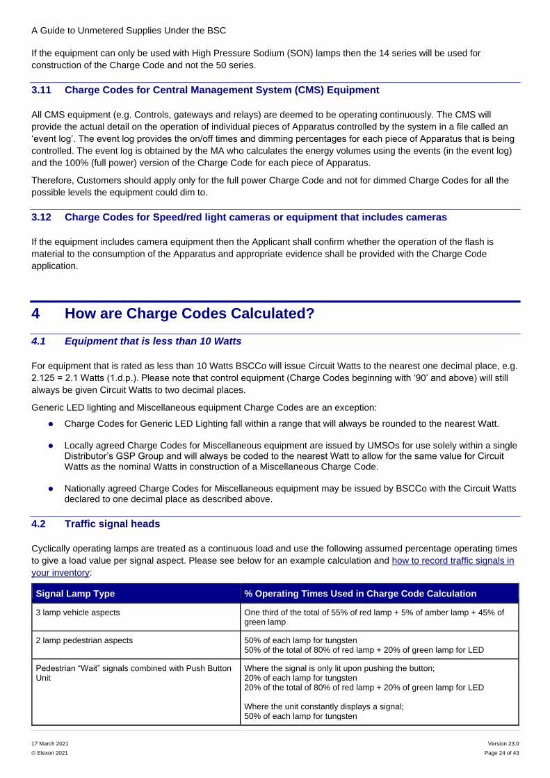
4.2 Traffic signal heads
Cyclically operating lamps are treated as a continuous load and use the following assumed percentage operating times
to give a load value per signal aspect. Please see below for an example calculation and how to record traffic signals in
your inventory:
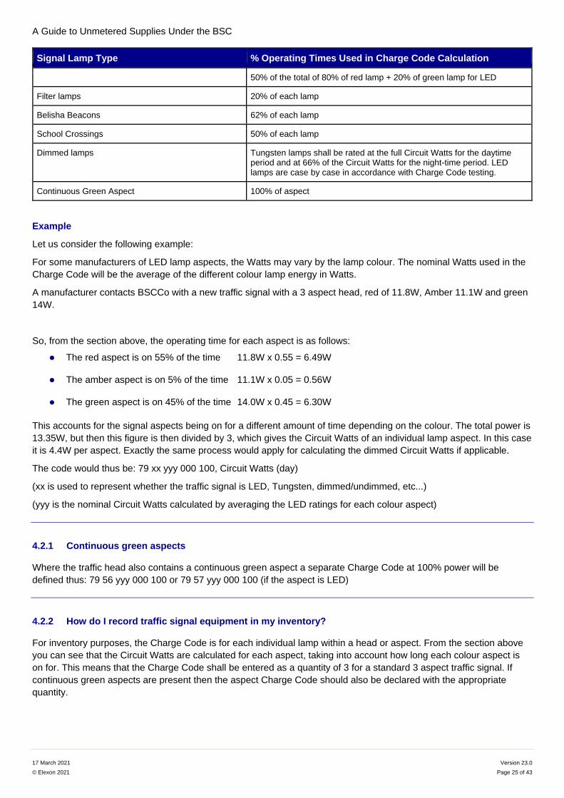
Signal Lamp Type % Operating Times Used in Charge Code Calculation
3 lamp vehicle aspects One third of the total of 55% of red lamp + 5% of amber lamp + 45% of green lamp
2 lamp pedestrian aspects 50% of each lamp for tungsten 50% of the total of 80% of red lamp + 20% of green lamp for LED
Pedestrian “Wait” signals combined with Push Button Unit
Where the signal is only lit upon pushing the button; 20% of each lamp for tungsten 20% of the total of 80% of red lamp + 20% of green lamp for LED Where the unit constantly displays a signal; 50% of each lamp for tungsten
A Guide to Unmetered Supplies Under the BSC
17 March 2021 Version 23.0
© Elexon 2021 Page 25 of 43
Signal Lamp Type % Operating Times Used in Charge Code Calculation
50% of the total of 80% of red lamp + 20% of green lamp for LED
Filter lamps 20% of each lamp
Belisha Beacons 62% of each lamp
School Crossings 50% of each lamp
Dimmed lamps Tungsten lamps shall be rated at the full Circuit Watts for the daytime period and at 66% of the Circuit Watts for the night-time period. LED lamps are case by case in accordance with Charge Code testing.
Continuous Green Aspect 100% of aspect
Example
Let us consider the following example:
For some manufacturers of LED lamp aspects, the Watts may vary by the lamp colour. The nominal Watts used in the
Charge Code will be the average of the different colour lamp energy in Watts.
A manufacturer contacts BSCCo with a new traffic signal with a 3 aspect head, red of 11.8W, Amber 11.1W and green
14W.
So, from the section above, the operating time for each aspect is as follows:
The red aspect is on 55% of the time 11.8W x 0.55 = 6.49W
The amber aspect is on 5% of the time 11.1W x 0.05 = 0.56W
The green aspect is on 45% of the time 14.0W x 0.45 = 6.30W
This accounts for the signal aspects being on for a different amount of time depending on the colour. The total power is
13.35W, but then this figure is then divided by 3, which gives the Circuit Watts of an individual lamp aspect. In this case
it is 4.4W per aspect. Exactly the same process would apply for calculating the dimmed Circuit Watts if applicable.
The code would thus be: 79 xx yyy 000 100, Circuit Watts (day)
(xx is used to represent whether the traffic signal is LED, Tungsten, dimmed/undimmed, etc...)
(yyy is the nominal Circuit Watts calculated by averaging the LED ratings for each colour aspect)
4.2.1 Continuous green aspects
Where the traffic head also contains a continuous green aspect a separate Charge Code at 100% power will be
defined thus: 79 56 yyy 000 100 or 79 57 yyy 000 100 (if the aspect is LED)
4.2.2 How do I record traffic signal equipment in my inventory?
For inventory purposes, the Charge Code is for each individual lamp within a head or aspect. From the section above
you can see that the Circuit Watts are calculated for each aspect, taking into account how long each colour aspect is
on for. This means that the Charge Code shall be entered as a quantity of 3 for a standard 3 aspect traffic signal. If
continuous green aspects are present then the aspect Charge Code should also be declared with the appropriate
quantity.
A Guide to Unmetered Supplies Under the BSC
17 March 2021 Version 23.0
© Elexon 2021 Page 26 of 43
4.2.3 Dimming Traffic Signals
All Traffic Signals take an electricity supply on a continuous basis and normally in an inventory would be allocated
against Switch Regime Code 001. However, large numbers of Traffic Signals can operate in a dimmed mode at night
through voltage reduction. The switch to dimmed mode is triggered by the operation of a Dusk to Dawn Photoelectric
Control Unit (PECU) (or time switch), which when switched on in the evening, causes the voltage to reduce. This
means that the equipment is now operating at the dimmed Watts (or night Watts) figure shown in the Charge Code
Spreadsheet. When the PECU switches off in the morning the voltage increases and the equipment operates at full
brightness and Circuit Watts in the Charge Code Spreadsheet.
When submitting such equipment in an inventory, the Switch Regime code for the PECU (or time switch) in the Switch
Regime Spreadsheet should be shown against that item.
If the item is traded on a NHH basis the operating hours to be used in the EAC calculation for the dimmed (Dusk to
Dawn) operation will be those shown against the relevant Switch Regime in the Switch Regime Spreadsheet, i.e. 821
for a 70/35 Lux electronic photocell.
For the day time (Dawn to Dusk) operation the hours to be used will be the continuous hours for Switch Regime 001
(8,766 hours) minus the dimmed hours. A worked example is shown below:
Take an inventory in the Midlands, which includes 300 x 50 Watt Red Amber Green Vehicle Aspects with a Charge
Code of 7902050000100. These are switched to dimmed operation by use of 70/35 Electronic PECUs which is Switch
Regime 821.
The calculation will be:
300 items x 12W x 4,150 hours / 1,000 = 14,940.0 kWh allocated to the Dusk to Dawn profile.
300 items x 18W x 4,616 (8,766-4,150) hours / 1,000 = 24,926.4 kWh allocated to the Dawn to Dusk profile.
If the item is traded on a HH basis the Equivalent Meter will work out bright and dimmed loads based on the hours of
operation of the relevant photocell.
4.2.4 Dummy Loads for LED Traffic Lights
A Dummy Load is required for some LED lights to increase the load so that a lamp monitor system will pick up if a lamp
fails. The dummy load is to be applied to the lamp Circuit Watts as part of the test process. Where evidence is provided
that different dummy loads are set dependent on equipment types then more than one Charge Code can be
constructed using the appropriate uplift.
4.2.5 What are filter signals?
The coding for a traffic light containing four or more aspects depends upon the use of the other aspects.
4 (or more) Signal Aspects
If the fourth aspect is on for the same time as another head, e.g. left arrow on at the same time as the straight ahead
signal, then a quantity of 4 must be associated with the corresponding 3 head lamp Charge Code.
If the length of time is the same as (or greater) than the green signal light, it shall be counted as a normal green signal
lamp. In this case a quantity of 4 (1 red + 1 amber + 2 green aspects) would be entered on the detailed inventory for
the relevant Charge Code.
Part of Green Sequence
If the fourth aspect is only on for part of the time, e.g. a right filter arrow on for part of the time of the straight ahead
signal, then a quantity of 3 shall be associated with the specific Charge Code and also a quantity of 1 shall be
associated with the correct Charge Code for the filter lamp head.
A Guide to Unmetered Supplies Under the BSC
17 March 2021 Version 23.0
© Elexon 2021 Page 27 of 43
Traffic filter signals are coded as 20% of the full Circuit Watts of the lamp to recognise that they are only illuminated for
part of the green sequence. The definition of a green filter signal is a green signal indicating movement for a specific
amount of time. This amount of time must be less than the time that the main green signal light is on for.
4.3 Cable network cabinets (Miscellaneous Codes Starting 813)
There are three approaches to establishing Charge Codes for fibre cable network cabinets, one of which is a legacy
arrangement established for a fibre cable network that was created by the merger of several regional operators into a
single national operator. The other two approaches are for newer fibre equipment, where Charge Codes are
established at either cabinet level or component level.
4.3.1 Legacy arrangement
The wide variety and different makes of equipment (power amplifiers, distribution amplifiers, etc.) used in
communication distribution cabinets makes it extremely difficult to provide an accurate breakdown of equipment for
each installation (with corresponding Charge Codes). In addition, a cabinet may be directly connected to the
Distribution Business’s network and then supply energy to equipment in other cabinets downstream of that cabinet, via
the Customer’s own communication network and associated private wiring.
It is therefore necessary to measure the actual load (spot check) at each exit point from the Distribution Business’s
network, and to quote the load applicable to each exit point in bands of 20 Watts (i.e. 400, 420, 440, etc.). The
Customer shall round to the nearest 20 Watts and declare those Watts on the inventory via a Charge Code.
As examples, if a particular load is measured at 458 Watts, then it is rounded to 460 Watts, whereas 448 would be
rounded to 440 Watts. The Charge Codes entered on the inventory would be 813 0460 000 100 and 813 0440 000
100, respectively.
4.3.2 Charge Codes at Cabinet Level
Cabinets will contain varying numbers and types of components depending on the number of end customers served by
the individual cabinet. Applications for Charge Codes shall include test results that enable the total electrical load at the
exit point from the Distribution Business’s network to be established for each potential cabinet component
configuration.
It is possible that the electrical load may vary for some components, for example dependant on factors such as
temperature (i.e. heating or cooling) or data load (end customer numbers). The application shall include details of
reasonable assumptions that have been made in determining the average load for such variations.
4.3.3 Charge Codes at Component Level
Where multiple configurations of one or more types or makes of equipment are used in an individual cabinet,
applications may be made for Charge Codes at component level.
Applications for Charge Codes shall include test results that enable the total electrical load at the exit point from the
Distribution Business’s network to be established by submission of an inventory including Charge Codes for all relevant
components installed in the individual cabinet.
It is possible that the electrical load may vary for some components, dependant on factors such as temperature (e.g.
heating or cooling) or data load (e.g. end customer numbers). The application shall include details of reasonable
assumptions that have been made in determining the average load for such variations.
A Guide to Unmetered Supplies Under the BSC
17 March 2021 Version 23.0
© Elexon 2021 Page 28 of 43
5 Not used
Content moved to Section 1.4.
6 Photoelectric Control Unit (PECU) array location and siting guidance
If there is disagreement regarding the location and siting of a Customer’s PECU array or the number of arrays required,
BSCP520 ‘Unmetered Supplies registered in SMRS’ makes reference to carrying out ‘research’.
This section is intended to expand on the type of research that can be considered by the MA and UMSO when
agreeing proposed locations.
6.1 Location of a single array
6.1.1 Weighted latitude and longitude of inventory
If there is latitude and longitude information contained in the Customer’s detailed inventory, it should be possible for the
MA and/or UMSO to perform a weighted longitude/latitude calculation to see where the ideal location of a single PECU
array should be.
6.1.2 Weighted latitude and longitude of population
If known, it is possible to perform the calculation described above but using the population figures of the various major
towns in the Customer’s area.
6.2 Deciding on multiple or single arrays
The number of arrays may be subject to decisions on the number of PECU types that can be populated in the array.
More than one array may be required if the population of PECUs for a Customer cannot be reasonably represented on
a single array of 30 PECUs. Furthermore, the size of the Customer’s area might require more than one array to
facilitate accurate calculation of Burn Hours. It is possible for the MA to calculate the Annual Burn Hours for any
latitude and longitude. If the differences between the proposed array sites are very small (i.e. less than +/- 2%) then
this would suggest that one array should be sufficient. If actual Burn Hours are available for existing arrays this data
could also be used.
6.3 Hosting and maintenance of the arrays
It is now common practice for the Customers to host PECU arrays. The MA is responsible for ensuring the siting of the
array complies with all the considerations of the PECU array siting procedures defined in BSCP520 ‘Unmetered
Supplies registered in SMRS’.
Where PECUs are identified for replacement the MA can direct the Customer to replace the PECU with an appropriate
PECU, taking into account the type and age and any changes to the Customer’s population of PECUs (keeping it
representative). The MA shall ensure on the next dial that the replaced cell is performing in line with expectations.
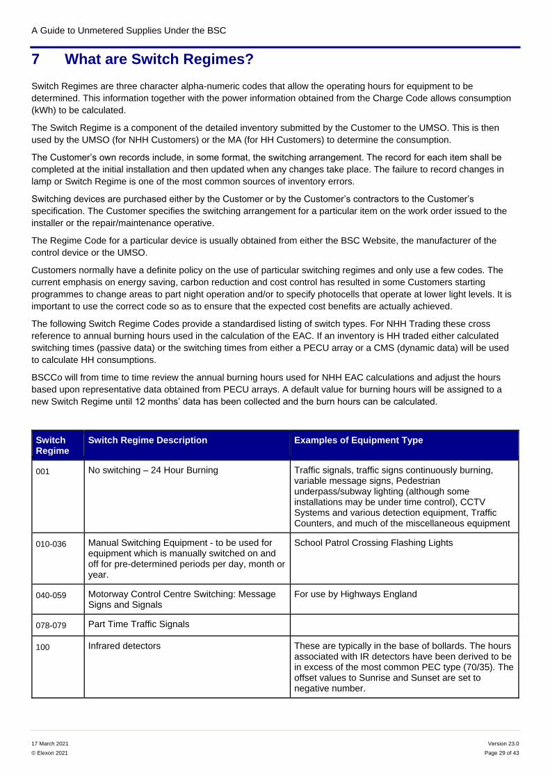
A Guide to Unmetered Supplies Under the BSC
17 March 2021 Version 23.0
© Elexon 2021 Page 29 of 43
7 What are Switch Regimes?
Switch Regimes are three character alpha-numeric codes that allow the operating hours for equipment to be
determined. This information together with the power information obtained from the Charge Code allows consumption
(kWh) to be calculated.
The Switch Regime is a component of the detailed inventory submitted by the Customer to the UMSO. This is then
used by the UMSO (for NHH Customers) or the MA (for HH Customers) to determine the consumption.
The Customer’s own records include, in some format, the switching arrangement. The record for each item shall be
completed at the initial installation and then updated when any changes take place. The failure to record changes in
lamp or Switch Regime is one of the most common sources of inventory errors.
Switching devices are purchased either by the Customer or by the Customer’s contractors to the Customer’s
specification. The Customer specifies the switching arrangement for a particular item on the work order issued to the
installer or the repair/maintenance operative.
The Regime Code for a particular device is usually obtained from either the BSC Website, the manufacturer of the
control device or the UMSO.
Customers normally have a definite policy on the use of particular switching regimes and only use a few codes. The
current emphasis on energy saving, carbon reduction and cost control has resulted in some Customers starting
programmes to change areas to part night operation and/or to specify photocells that operate at lower light levels. It is
important to use the correct code so as to ensure that the expected cost benefits are actually achieved.
The following Switch Regime Codes provide a standardised listing of switch types. For NHH Trading these cross
reference to annual burning hours used in the calculation of the EAC. If an inventory is HH traded either calculated
switching times (passive data) or the switching times from either a PECU array or a CMS (dynamic data) will be used
to calculate HH consumptions.
BSCCo will from time to time review the annual burning hours used for NHH EAC calculations and adjust the hours
based upon representative data obtained from PECU arrays. A default value for burning hours will be assigned to a
new Switch Regime until 12 months’ data has been collected and the burn hours can be calculated.
Switch Regime
Switch Regime Description Examples of Equipment Type
001 No switching – 24 Hour Burning Traffic signals, traffic signs continuously burning, variable message signs, Pedestrian underpass/subway lighting (although some installations may be under time control), CCTV Systems and various detection equipment, Traffic Counters, and much of the miscellaneous equipment
010-036 Manual Switching Equipment - to be used for equipment which is manually switched on and off for pre-determined periods per day, month or year.
School Patrol Crossing Flashing Lights
040-059 Motorway Control Centre Switching: Message Signs and Signals
For use by Highways England
078-079 Part Time Traffic Signals
100 Infrared detectors These are typically in the base of bollards. The hours associated with IR detectors have been derived to be in excess of the most common PEC type (70/35). The offset values to Sunrise and Sunset are set to negative number.
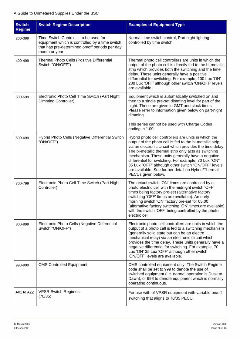
A Guide to Unmetered Supplies Under the BSC
17 March 2021 Version 23.0
© Elexon 2021 Page 30 of 43
Switch Regime
Switch Regime Description Examples of Equipment Type
200-399 Time Switch Control - - to be used for equipment which is controlled by a time switch that has pre-determined on/off periods per day, month or year.
Normal time switch control, Part night lighting controlled by time switch
400-499 Thermal Photo Cells (Positive Differential Switch "ON/OFF")
Thermal photo cell controllers are units in which the output of the photo cell is directly fed to the bi-metallic strip which provides both the switching and the time delay. These units generally have a positive differential for switching. For example, 100 Lux ‘ON’ 200 Lux ‘OFF’ although other switch ‘ON/OFF’ levels are available.
500-599 Electronic Photo Cell Time Switch (Part Night Dimming Controller)
Equipment which is automatically switched on and then to a single pre-set dimming level for part of the night. These are given in GMT and clock times. Please refer to information given below on part-night dimming. This series cannot be used with Charge Codes ending in ‘100’.
600-699 Hybrid Photo Cells (Negative Differential Switch "ON/OFF")
Hybrid photo cell controllers are units in which the output of the photo cell is fed to the bi-metallic strip via an electronic circuit which provides the time delay. The bi-metallic thermal strip only acts as switching mechanism. These units generally have a negative differential for switching. For example, 70 Lux "ON" 35 Lux "OFF" although other switch "ON/OFF" levels are available. See further detail on Hybrid/Thermal PECUs given below.
700-799 Electronic Photo Cell Time Switch (Part Night Controller)
The actual switch ‘ON’ times are controlled by a photo electric cell with the midnight switch ‘OFF’ times being factory pre-set (alternative factory switching ‘OFF’ times are available). An early morning switch ‘ON’ factory pre-set for 05.00 (alternative factory switching ‘ON’ times are available) with the switch ‘OFF’ being controlled by the photo electric cell.
800-899 Electronic Photo Cells (Negative Differential Switch "ON/OFF")
Electronic photo cell controllers are units in which the output of a photo cell is fed to a switching mechanism (generally solid state but can be an electro mechanical relay) via an electronic circuit which provides the time delay. These units generally have a negative differential for switching. For example, 70 Lux ‘ON’ 35 Lux ’OFF’ although other switch ‘ON/OFF’ levels are available.
998-999 CMS Controlled Equipment CMS controlled equipment only. The Switch Regime code shall be set to 999 to denote the use of switched equipment (i.e. normal operation is Dusk to Dawn), or 998 to denote equipment which is normally operating continuous.
A01 to AZZ VPSR Switch Regimes: (70/35)
For use with of VPSR equipment with variable on/off
switching that aligns to 70/35 PECU.
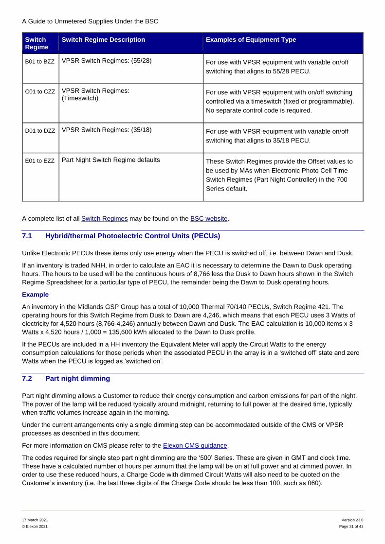
A Guide to Unmetered Supplies Under the BSC
17 March 2021 Version 23.0
© Elexon 2021 Page 31 of 43
Switch Regime
Switch Regime Description Examples of Equipment Type
B01 to BZZ VPSR Switch Regimes: (55/28) For use with VPSR equipment with variable on/off
switching that aligns to 55/28 PECU.
C01 to CZZ VPSR Switch Regimes: (Timeswitch)
For use with VPSR equipment with on/off switching
controlled via a timeswitch (fixed or programmable).
No separate control code is required.
D01 to DZZ VPSR Switch Regimes: (35/18) For use with VPSR equipment with variable on/off
switching that aligns to 35/18 PECU.
E01 to EZZ Part Night Switch Regime defaults These Switch Regimes provide the Offset values to
be used by MAs when Electronic Photo Cell Time
Switch Regimes (Part Night Controller) in the 700
Series default.
A complete list of all Switch Regimes may be found on the BSC website.
7.1 Hybrid/thermal Photoelectric Control Units (PECUs)
Unlike Electronic PECUs these items only use energy when the PECU is switched off, i.e. between Dawn and Dusk.
If an inventory is traded NHH, in order to calculate an EAC it is necessary to determine the Dawn to Dusk operating
hours. The hours to be used will be the continuous hours of 8,766 less the Dusk to Dawn hours shown in the Switch
Regime Spreadsheet for a particular type of PECU, the remainder being the Dawn to Dusk operating hours.
Example
An inventory in the Midlands GSP Group has a total of 10,000 Thermal 70/140 PECUs, Switch Regime 421. The
operating hours for this Switch Regime from Dusk to Dawn are 4,246, which means that each PECU uses 3 Watts of
electricity for 4,520 hours (8,766-4,246) annually between Dawn and Dusk. The EAC calculation is 10,000 items x 3
Watts x 4,520 hours / 1,000 = 135,600 kWh allocated to the Dawn to Dusk profile.
If the PECUs are included in a HH inventory the Equivalent Meter will apply the Circuit Watts to the energy
consumption calculations for those periods when the associated PECU in the array is in a ‘switched off’ state and zero
Watts when the PECU is logged as ‘switched on’.
7.2 Part night dimming
Part night dimming allows a Customer to reduce their energy consumption and carbon emissions for part of the night.
The power of the lamp will be reduced typically around midnight, returning to full power at the desired time, typically
when traffic volumes increase again in the morning.
Under the current arrangements only a single dimming step can be accommodated outside of the CMS or VPSR
processes as described in this document.
For more information on CMS please refer to the Elexon CMS guidance.
The codes required for single step part night dimming are the ‘500’ Series. These are given in GMT and clock time.
These have a calculated number of hours per annum that the lamp will be on at full power and at dimmed power. In
order to use these reduced hours, a Charge Code with dimmed Circuit Watts will also need to be quoted on the
Customer’s inventory (i.e. the last three digits of the Charge Code should be less than 100, such as 060).
A Guide to Unmetered Supplies Under the BSC
17 March 2021 Version 23.0
© Elexon 2021 Page 32 of 43
Part night cells are a direct plug-in replacement for normal photocells. They can either simply switch the load ‘ON’,
‘OFF’, ‘ON’, ‘OFF’ during the night or ‘ON’, ‘DIM’, ‘BRIGHT’, ‘OFF’ according to the type of cell and the particular
equipment they are controlling. In the middle of summer, the cells may not switch back ‘ON’ in the morning.
Typically, they calculate midnight by determining the mid-point of the last three on-off cycles then switch the load ‘ON’,
‘DIM’ and ‘OFF’ at the times already programmed into the cell at the time of manufacture.
A more sophisticated version is available that adjusts for the change from GMT to BST and back to GMT. The
transition is triggered when the time that the cell is switched ‘ON’ during 24 hours equals the time the cell is switched
‘OFF’.
E.g. Assuming a Customer has a SELC 4000 ECONO 100 Watt Part Night Ballast (Dimmed 72% Circuit Watts). The
Customer wants to benefit from the dimming available. They contact their UMSO to inform them that they are now
dimming their lamps from 23:00 to 05:00.
The Customer would update the Switch Regime in their inventory to 530. They would also need to quote the correct
Charge Code: 14 0100 5004 072.
To calculate the energy consumption (using the NHH hours published for the Eastern GSP Group) the following would
apply;
Bright Hours = 2468, Dimmed Hours = 1683, Full Power Circuit Watts = 110, Dimmed Circuit Watts = 79
(1683 x 79) / 1000 + (2468 x 110) / 1000
= Dimmed Consumption 132.96 + Full Power Consumption 271.48
= 404 kWh per annum (to the nearest kWh)
For a full list of Charge Codes that support dimming please see the Charge Code Spreadsheet.
7.3 Variable Power Switch Regime (VPSR) Switch Regimes
A Customer (or the driver/ballast manufacturer) can apply for a VPSR Switch Regime from BSCCo. The application
can be made for a single change in power level or up to eight different power levels, including the 100% level, in a 24-
hour period. These Switch Regimes can only be paired with Charge Codes that have ‘100’ as their last three digits.
The manufacturer or lighting engineer can set the Apparatus to any dimming level between 10% and 85% of full power
(noting the limit of eight events). However, when applying for the VPSR Switch Regimes the Applicant should round the
dimming levels to the nearest 5% boundary (percentages ending in a 0 or a 5).
More specifically, if the dimming % ends in a 1, 2, 8 or 9 then round to nearest % ending 0. If dimming % ends 3, 4, 6
or 7 rounds to nearest dimming % ending in a 5.
E.g. Assuming dimming % are always whole numbers and the Apparatus is physically set to dim to 52% of full power at
02:00 hours and to 68% full power at 04:00 hours. The application for a Switch Regime would be for 50% of full power
at 02:00 hours and 70% full power at 04:00 hours.
The Applicant will also declare if the switch times are in Co-ordinated Universal Time (UTC) (equivalent of Greenwich
Mean Time (GMT)) or if the times are ‘Clock Time’ (GMT in winter and British Summer Time (BST) in summer).
Where a dimming device can be configured remotely or locally, prior to making any changes to the dimming pattern,
the Customer must ensure that a suitable Variable Power Switch Regime (VPSR), which matches the new dimming
pattern, is defined in the Variable Power Switch Regime Spreadsheet on the BSC website. If a suitable VPSR is not
already approved, the customer or a representative, must complete an application for a new VPSR, which needs to be
approved and published before changing the operation of the device.
Once the device has been re-configured the Customer must immediately provide a new inventory to the UMSO
declaring the appropriate VPSR.
The Switch Regime will be calculated based on a 70/35, 55/28, 35/18 or 20/20 Lux PECU or Time Switches.
A Guide to Unmetered Supplies Under the BSC
17 March 2021 Version 23.0
© Elexon 2021 Page 33 of 43
7.4 Variable Power Switch Regime Spreadsheet
The Variable Power Switch Regime Spreadsheet displays all events and percentages on a single line, to allow users to
filter entries. A single-step dimming to 50% would give the following information:
Switch Regime: 01A (UTC)
On Event: PECU
Power %: 100
Switch Event 2 Time: 01:00
Switch Event 2 Power % Energy: 50
Switch Event 3 Time: 05:00
Switch Event 3 Power % Energy: 100
Off Event: PECU
The Switch Regime Spreadsheet shows the average Burn Hours (if at full Circuit Watts) used to calculate the NHH
EAC.
7.4.1 Energy calculation for dimming of Generic LED Lighting Charge Codes ending ‘100’
This is the energy calculation for single or VPSR dimming using Generic LED Lighting Charge Codes or other Charge
Codes ending ‘100’. Where a Customer purchases their unmetered energy on a HH basis, the MA uses the VPSR
dimming approach for both multi and single step dimming. That is, they will enter the dimming level and timings
indicated by the Switch Regimes into the Equivalent Meter. Any percentage reduction in power will then be applied to
the full Circuit Watts at the indicated times. The energy calculations that determine the HH consumption values for the
LED lighting Apparatus will reflect the dimming (reduced power).
Where a Customer purchases their unmetered energy on a NHH basis, this requires the UMSO to estimate the annual
consumption of the Apparatus (the EAC).
For a 100 Watt Generic LED street light dimmed from 01:00 to 05:00 hours (UTC) with Switch Regime Burn Hours of
3496 hours per year the calculation would be:
100 Watts * 3496 Hours = 349.6 kWh per year
We calculated this using the Burn Hours (3496 hours) and converting to kWh, using a generic Charge Code ending
‘100’ (e.g. 42 0100 000 100).
7.5 Highway Message and Indicator Sign operating hours
Annual operating hours for the Bright and Dim load will be calculated by Highways England based on actual
operational information. These are updated periodically and issued to UMSOs & MAs. For NHH trading the annual
hours issued by Highways England will be used in the EAC calculation. Daily switching events will be defined by the
MA to replicate the Switch Regime annual hours for HH trading.
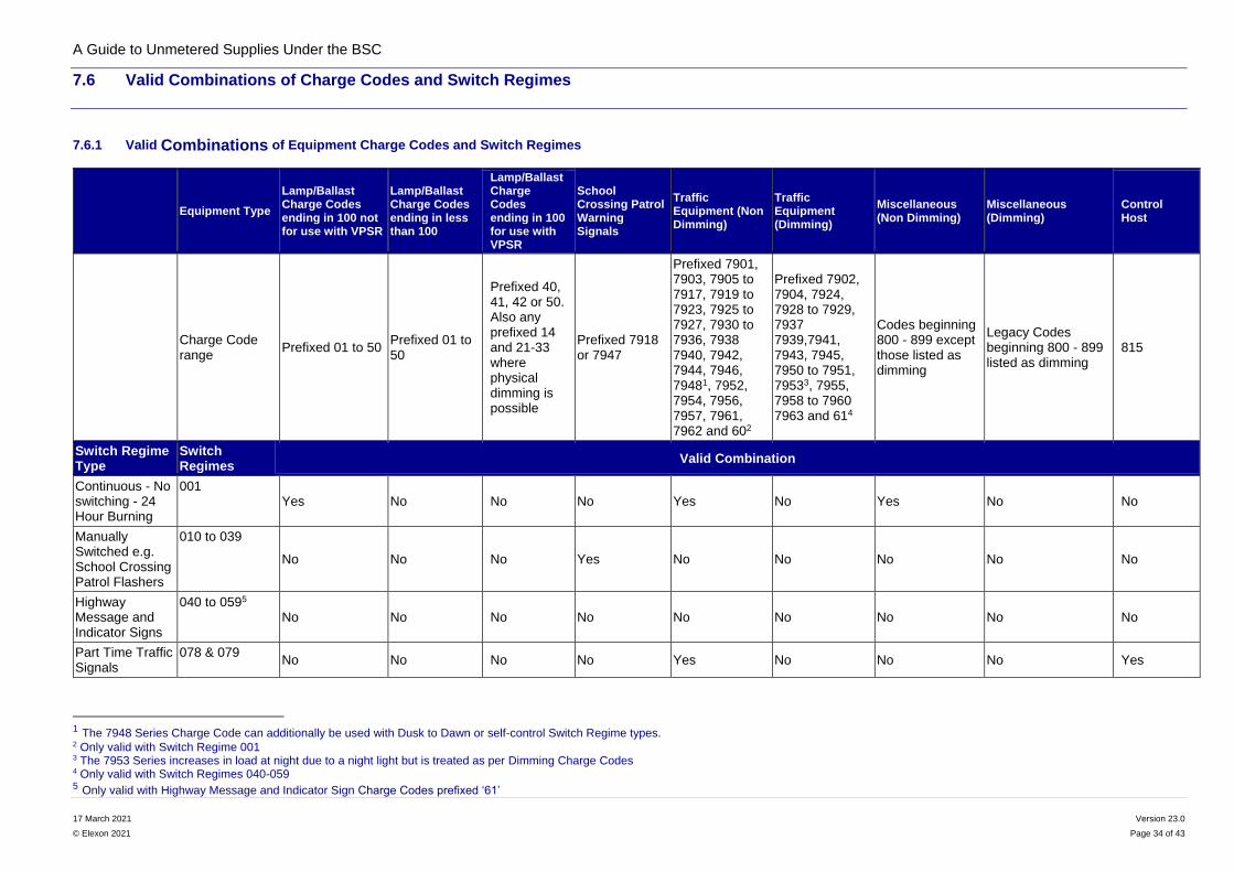
A Guide to Unmetered Supplies Under the BSC
17 March 2021 Version 23.0
© Elexon 2021 Page 34 of 43
7.6 Valid Combinations of Charge Codes and Switch Regimes
7.6.1 Valid Combinations of Equipment Charge Codes and Switch Regimes
Equipment Type
Lamp/Ballast Charge Codes ending in 100 not for use with VPSR
Lamp/Ballast Charge Codes ending in less than 100
Lamp/Ballast Charge Codes ending in 100 for use with VPSR
School Crossing Patrol Warning Signals
Traffic Equipment (Non Dimming)
Traffic Equipment (Dimming)
Miscellaneous (Non Dimming)
Miscellaneous (Dimming)
Control Host
Charge Code range
Prefixed 01 to 50 Prefixed 01 to 50
Prefixed 40, 41, 42 or 50. Also any prefixed 14 and 21-33 where physical dimming is possible
Prefixed 7918 or 7947
Prefixed 7901, 7903, 7905 to 7917, 7919 to 7923, 7925 to 7927, 7930 to 7936, 7938 7940, 7942, 7944, 7946, 79481, 7952, 7954, 7956, 7957, 7961, 7962 and 602
Prefixed 7902, 7904, 7924, 7928 to 7929, 7937 7939,7941, 7943, 7945, 7950 to 7951, 79533, 7955, 7958 to 7960 7963 and 614
Codes beginning 800 - 899 except those listed as dimming
Legacy Codes beginning 800 - 899 listed as dimming
815
Switch Regime Type
Switch Regimes
Valid Combination
Continuous - No switching - 24 Hour Burning
001 Yes No No No Yes No Yes No No
Manually Switched e.g. School Crossing Patrol Flashers
010 to 039
No No No Yes No No No No No
Highway Message and Indicator Signs
040 to 0595 No No No No No No No No No
Part Time Traffic Signals
078 & 079 No No No No Yes No No No Yes
1 The 7948 Series Charge Code can additionally be used with Dusk to Dawn or self-control Switch Regime types. 2 Only valid with Switch Regime 001 3 The 7953 Series increases in load at night due to a night light but is treated as per Dimming Charge Codes 4 Only valid with Switch Regimes 040-059 5 Only valid with Highway Message and Indicator Sign Charge Codes prefixed ‘61’
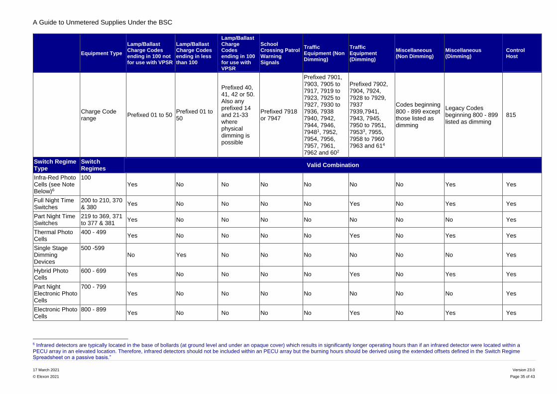
A Guide to Unmetered Supplies Under the BSC
17 March 2021 Version 23.0
© Elexon 2021 Page 35 of 43
Equipment Type
Lamp/Ballast Charge Codes ending in 100 not for use with VPSR
Lamp/Ballast Charge Codes ending in less than 100
Lamp/Ballast Charge Codes ending in 100 for use with VPSR
School Crossing Patrol Warning Signals
Traffic Equipment (Non Dimming)
Traffic Equipment (Dimming)
Miscellaneous (Non Dimming)
Miscellaneous (Dimming)
Control Host
Charge Code range
Prefixed 01 to 50 Prefixed 01 to 50
Prefixed 40, 41, 42 or 50. Also any prefixed 14 and 21-33 where physical dimming is possible
Prefixed 7918 or 7947
Prefixed 7901, 7903, 7905 to 7917, 7919 to 7923, 7925 to 7927, 7930 to 7936, 7938 7940, 7942, 7944, 7946, 79481, 7952, 7954, 7956, 7957, 7961, 7962 and 602
Prefixed 7902, 7904, 7924, 7928 to 7929, 7937 7939,7941, 7943, 7945, 7950 to 7951, 79533, 7955, 7958 to 7960 7963 and 614
Codes beginning 800 - 899 except those listed as dimming
Legacy Codes beginning 800 - 899 listed as dimming
815
Switch Regime Type
Switch Regimes
Valid Combination
Infra-Red Photo Cells (see Note Below)6
100 Yes No No No No No No Yes Yes
Full Night Time Switches
200 to 210, 370 & 380
Yes No No No No Yes No Yes Yes
Part Night Time Switches
219 to 369, 371 to 377 & 381
Yes No No No No No No No Yes
Thermal Photo Cells
400 - 499 Yes No No No No Yes No Yes Yes
Single Stage Dimming Devices
500 -599 No Yes No No No No No No Yes
Hybrid Photo Cells
600 - 699 Yes No No No No Yes No Yes Yes
Part Night Electronic Photo Cells
700 - 799 Yes No No No No No No No Yes
Electronic Photo Cells
800 - 899 Yes No No No No Yes No Yes Yes
6 Infrared detectors are typically located in the base of bollards (at ground level and under an opaque cover) which results in significantly longer operating hours than if an infrared detector were located within a PECU array in an elevated location. Therefore, infrared detectors should not be included within an PECU array but the burning hours should be derived using the extended offsets defined in the Switch Regime Spreadsheet on a passive basis.”
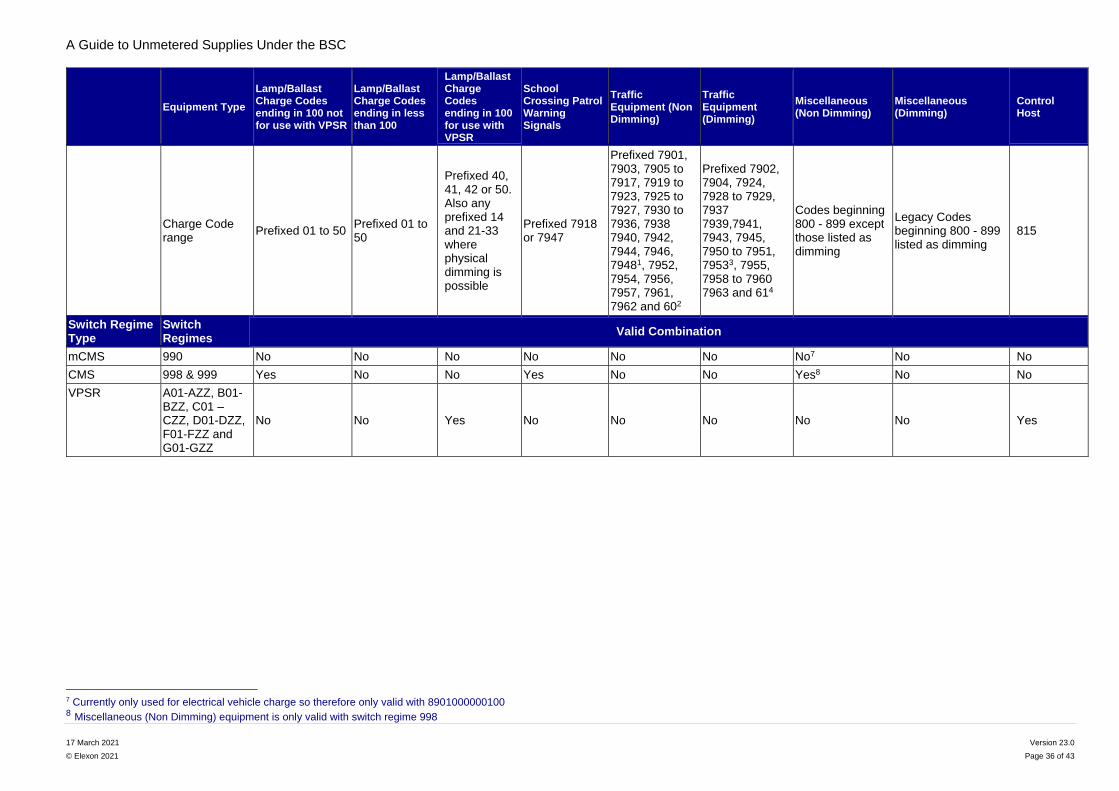
A Guide to Unmetered Supplies Under the BSC
17 March 2021 Version 23.0
© Elexon 2021 Page 36 of 43
Equipment Type
Lamp/Ballast Charge Codes ending in 100 not for use with VPSR
Lamp/Ballast Charge Codes ending in less than 100
Lamp/Ballast Charge Codes ending in 100 for use with VPSR
School Crossing Patrol Warning Signals
Traffic Equipment (Non Dimming)
Traffic Equipment (Dimming)
Miscellaneous (Non Dimming)
Miscellaneous (Dimming)
Control Host
Charge Code range
Prefixed 01 to 50 Prefixed 01 to 50
Prefixed 40, 41, 42 or 50. Also any prefixed 14 and 21-33 where physical dimming is possible
Prefixed 7918 or 7947
Prefixed 7901, 7903, 7905 to 7917, 7919 to 7923, 7925 to 7927, 7930 to 7936, 7938 7940, 7942, 7944, 7946, 79481, 7952, 7954, 7956, 7957, 7961, 7962 and 602
Prefixed 7902, 7904, 7924, 7928 to 7929, 7937 7939,7941, 7943, 7945, 7950 to 7951, 79533, 7955, 7958 to 7960 7963 and 614
Codes beginning 800 - 899 except those listed as dimming
Legacy Codes beginning 800 - 899 listed as dimming
815
Switch Regime Type
Switch Regimes
Valid Combination
mCMS 990 No No No No No No No7 No No
CMS 998 & 999 Yes No No Yes No No Yes8 No No
VPSR A01-AZZ, B01-BZZ, C01 – CZZ, D01-DZZ, F01-FZZ and G01-GZZ
No No Yes No No No No No Yes
7 Currently only used for electrical vehicle charge so therefore only valid with 8901000000100 8 Miscellaneous (Non Dimming) equipment is only valid with switch regime 998

A Guide to Unmetered Supplies Under the BSC
17 March 2021 Version 23.0
© Elexon 2021 Page 37 of 43
7.6.2 Valid Combinations of Control Charge Codes and Switch Regimes
Description
Time Switch
Controls
Thermal
Photocells
Hybrid
Photocel
ls
Electronic
Photocells
Electronic
Photocells
(Latching relay)
[Discontinued]
Infra-Red
Photocells
Electronic
Photo Cell
Timeswitch
[Discontinue
d]
Electronic
Controls (e.g.
CMS
devices)9
VPSR Controls
and Controls
integral to
Ballasts
Equipment Code 91 92 93 94 95 96 97 98 99
Switch Regime Type Switch Regime Valid Combinations
Continuous - No
switching - 24 Hour
Burning
001
No No No No No No No No/Yes No
Manually Switched
e.g. School
Crossing Patrol
Flashers
010 to 039
Yes No No Yes No No No Yes No
Highway Message and Indicator Signs
040 to 059 No No No No No No No No No
Part Time Traffic Signals
078 to 079 Yes No No No No No No No No
Infra-Red Photo
Cells
100 No No No No No Yes No No No
Time Switches 200 to 399 Yes No No No No No No No No
Thermal Photo Cells 400 - 499 No Yes No No No No No No No
Single Stage
Dimming Devices
500 -599 Yes Yes Yes Yes Yes No Yes No/Yes Yes
Hybrid Photo Cells 600 - 699 No No Yes No No No No No No
Part Night Electronic
Photo Cells
700 - 799 No No No Yes Yes No Yes No/Yes No
Electronic Photo Cells 800 - 899 No No No Yes Yes No Yes No/Yes No
9 Where “No/Yes” is shown, ‘Yes’ is only applicable where the UMSO has agreed to a small scale CMS trial or has made inventory amendments
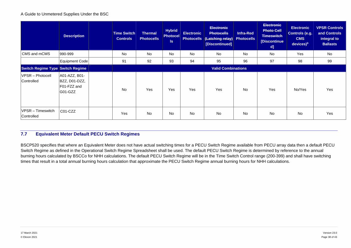
A Guide to Unmetered Supplies Under the BSC
17 March 2021 Version 23.0
© Elexon 2021 Page 38 of 43
Description
Time Switch
Controls
Thermal
Photocells
Hybrid
Photocel
ls
Electronic
Photocells
Electronic
Photocells
(Latching relay)
[Discontinued]
Infra-Red
Photocells
Electronic
Photo Cell
Timeswitch
[Discontinue
d]
Electronic
Controls (e.g.
CMS
devices)9
VPSR Controls
and Controls
integral to
Ballasts
CMS and mCMS 990-999 No No No No No No No Yes No
Equipment Code 91 92 93 94 95 96 97 98 99
Switch Regime Type Switch Regime Valid Combinations
VPSR – Photocell
Controlled
A01-AZZ, B01-
BZZ, D01-DZZ,
F01-FZZ and
G01-GZZ
No Yes Yes Yes Yes No Yes No/Yes Yes
VPSR – Timeswitch
Controlled C01-CZZ
Yes No No No No No No No Yes
7.7 Equivalent Meter Default PECU Switch Regimes
BSCP520 specifies that where an Equivalent Meter does not have actual switching times for a PECU Switch Regime available from PECU array data then a default PECU
Switch Regime as defined in the Operational Switch Regime Spreadsheet shall be used. The default PECU Switch Regime is determined by reference to the annual
burning hours calculated by BSCCo for NHH calculations. The default PECU Switch Regime will be in the Time Switch Control range (200-399) and shall have switching
times that result in a total annual burning hours calculation that approximate the PECU Switch Regime annual burning hours for NHH calculations.

A Guide to Unmetered Supplies Under the BSC
17 March 2021 Version 23.0
© Elexon 2021 Page 39 of 43
8. Standard file format for detailed inventories
Customers should maintain an inventory of their unmetered equipment to enable them to populate a file with the data
described in this section. Where typical unmetered equipment is supplied by a metered feeder pillar then this should be
recorded in the inventory system and not included within the inventory submitted to the UMSO. Otherwise the
consumption will be charged for twice.
Customers may have equipment connected to more than one Distribution Network. It is therefore important that the inventory identifies which Network Operator is providing the connection for each item of unmetered equipment, so that the inventory can be submitted to the correct UMSO (see also Field 16 of the Standard Inventory Format and the explanatory notes).
8.1 General comments
This format has been developed to provide the information required for the operation of BSCP520 and the auditing requirements of Distribution Businesses in a standard way. Provision of an inventory in this format will be accepted by all UMSOs. It is expected to be of particular benefit to Customers with unmetered equipment in more than one Distribution Licence area and to suppliers of inventory software who wish to provide a standard extract package for their Customers.
It is NOT intended to supersede existing arrangements where both the Customer and the Distribution Business agree to continue with a different format.
The inventory shall be submitted either as a fixed format text file, a spreadsheet compatible with Excel, or as a comma
separated file with a line for each item of inventory. The data, with the originator clearly identified, shall be attached to
an email.
Submissions made as a comma separated file should be checked carefully to ensure formatting includes leading zeros
as necessary and as described in the notes at 8.3. Unless noted below, the field lengths apply to fixed format text files only, e.g. No. of items does not need leading zeros in a spreadsheet or CSV file.
The file format below is that which shall be supplied by the Customer or as otherwise agreed with the UMSO. The file format shall contain, as a minimum, the following information:
a) a list of items of unmetered equipment providing a unique identification and geographical location of each item;
b) the number of items of each category of unmetered equipment, classified by Charge Code and Switch Regime. Items not able to be so classified shall be identified and quantified separately;
c) the nominal rating for each Charge Code shall be indicated; and
d) the Switch Regime for each UMS equipment. Items not able to be so classified shall be identified separately.
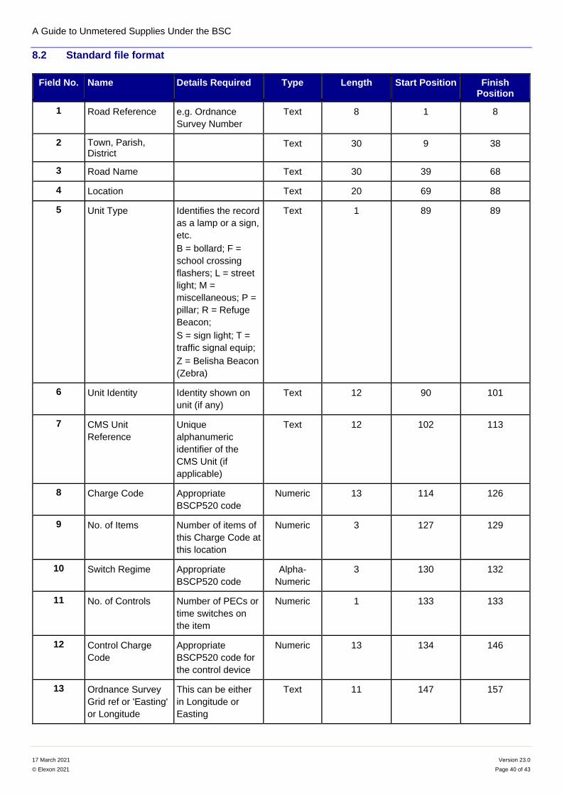
A Guide to Unmetered Supplies Under the BSC
17 March 2021 Version 23.0
© Elexon 2021 Page 40 of 43
8.2 Standard file format
Field No. Name Details Required Type Length Start Position Finish Position
1 Road Reference e.g. Ordnance
Survey Number
Text 8 1 8
2 Town, Parish, District
Text 30 9 38
3 Road Name Text 30 39 68
4 Location Text 20 69 88
5 Unit Type Identifies the record
as a lamp or a sign,
etc.
B = bollard; F =
school crossing
flashers; L = street
light; M =
miscellaneous; P =
pillar; R = Refuge
Beacon;
S = sign light; T =
traffic signal equip;
Z = Belisha Beacon
(Zebra)
Text 1 89 89
6 Unit Identity Identity shown on
unit (if any)
Text 12 90 101
7 CMS Unit
Reference
Unique
alphanumeric
identifier of the
CMS Unit (if
applicable)
Text 12 102 113
8 Charge Code Appropriate
BSCP520 code
Numeric 13 114 126
9 No. of Items Number of items of
this Charge Code at
this location
Numeric 3 127 129
10 Switch Regime Appropriate
BSCP520 code
Alpha-
Numeric
3 130 132
11 No. of Controls Number of PECs or
time switches on
the item
Numeric 1 133 133
12 Control Charge
Code
Appropriate
BSCP520 code for
the control device
Numeric 13 134 146
13 Ordnance Survey
Grid ref or 'Easting'
or Longitude
This can be either
in Longitude or
Easting
Text 11 147 157
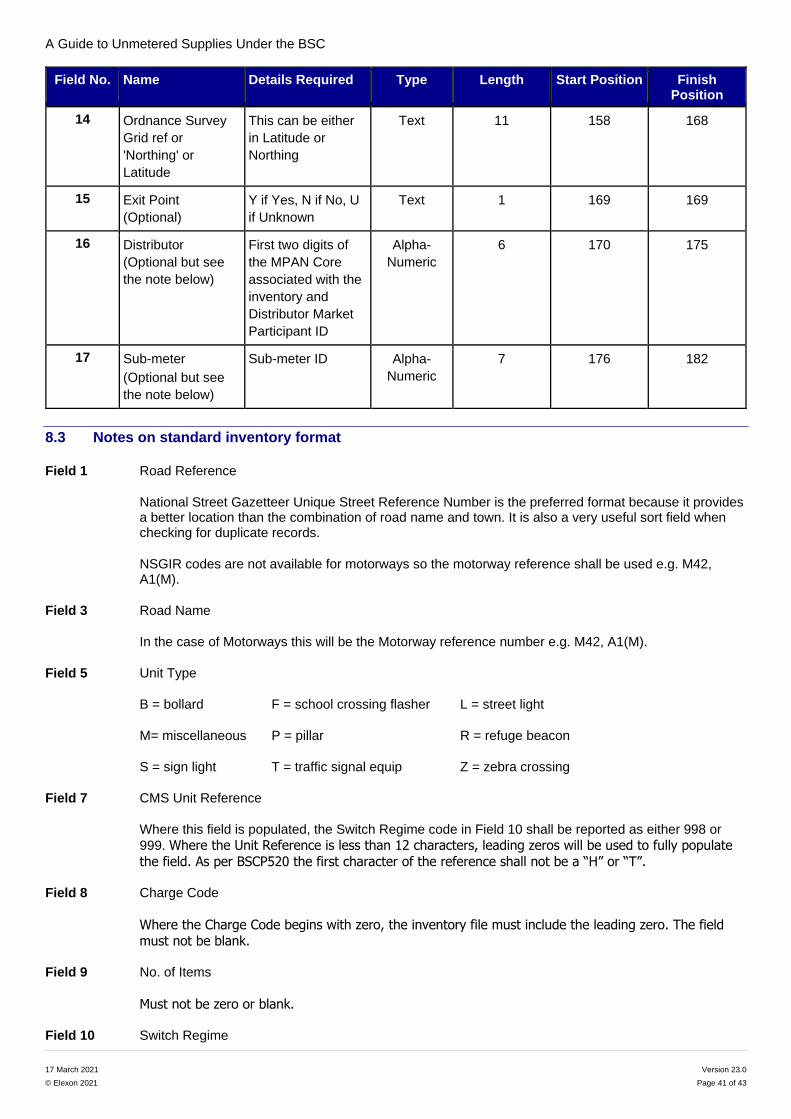
A Guide to Unmetered Supplies Under the BSC
17 March 2021 Version 23.0
© Elexon 2021 Page 41 of 43
Field No. Name Details Required Type Length Start Position Finish Position
14 Ordnance Survey
Grid ref or
'Northing' or
Latitude
This can be either
in Latitude or
Northing
Text 11 158 168
15 Exit Point
(Optional)
Y if Yes, N if No, U
if Unknown
Text 1 169 169
16 Distributor
(Optional but see
the note below)
First two digits of
the MPAN Core
associated with the
inventory and
Distributor Market
Participant ID
Alpha-
Numeric
6 170 175
17 Sub-meter
(Optional but see
the note below)
Sub-meter ID Alpha-
Numeric
7 176 182
8.3 Notes on standard inventory format
Field 1 Road Reference
National Street Gazetteer Unique Street Reference Number is the preferred format because it provides a better location than the combination of road name and town. It is also a very useful sort field when checking for duplicate records.
NSGIR codes are not available for motorways so the motorway reference shall be used e.g. M42, A1(M).
Field 3 Road Name
In the case of Motorways this will be the Motorway reference number e.g. M42, A1(M).
Field 5 Unit Type
B = bollard F = school crossing flasher L = street light
M= miscellaneous P = pillar R = refuge beacon
S = sign light T = traffic signal equip Z = zebra crossing
Field 7 CMS Unit Reference
Where this field is populated, the Switch Regime code in Field 10 shall be reported as either 998 or
999. Where the Unit Reference is less than 12 characters, leading zeros will be used to fully populate
the field. As per BSCP520 the first character of the reference shall not be a “H” or “T”.
Field 8 Charge Code
Where the Charge Code begins with zero, the inventory file must include the leading zero. The field must not be blank.
Field 9 No. of Items
Must not be zero or blank.
Field 10 Switch Regime
A Guide to Unmetered Supplies Under the BSC
17 March 2021 Version 23.0
© Elexon 2021 Page 42 of 43
Where the Switch Regime begins with zero, the inventory file must include the leading zero(s). The field must not be blank.
Field 11 No. of Controls
If no controls are fitted, the entry can be zero or blank.
In the case of isolation pillars which only contain a time control device and no other load consuming device then the number of time control devices shall be entered here and the appropriate Control Charge Code in field 12. The Control Host Charge Code shall be entered in field 8, with an appropriate No. of Items in field 9.
Field 12 Control Charge Code
If no controls are fitted, the entry can be zero or blank.
Fields 13, 14 Grid References or Latitude and Longitude.
Data is to be inserted in these fields when available. The increasing use of GPS equipment provides very accurate location data which may supplement or be in addition to the location in Field 4.
Field 15 Exit Point (Optional)
A ‘Y’ identifies if the equipment is connected directly to the Distribution network, a ‘N’ indicates fed via some private distribution network, i.e. a sign light looped from a lighting column, or column fed from private distribution cables.
Field 16 Distributor (Optional but see the note below)
This field must be populated where agreement has been reached to include Apparatus connected to the embedded network(s) of more than one Distributor in a single combined inventory, as this identifies which Network Operator (Distributor) owns the connection. The first two characters will be the first two digits of the MPAN Core (i.e. the Distributor Identifier or ‘short code’) associated with the inventory. The last four characters will be the Market Participant Identifier (MPID) for the embedded Distributor.
Example: If a council had Apparatus connected to an embedded network in the South Eastern Power Networks distribution area, the first two digits of this field would be ‘19’. If that embedded network was operated by ESP Electricity Ltd (MPID: LENG), then the Apparatus would have an entry in the inventory of ‘19LENG’.
Note: All Distributors’ MPIDs can be found in the list of Qualified Persons on the BSC website: List of Qualified Persons Spreadsheet.
Field 17 Sub-Meter (Optional but see the note below)
This field must be populated where the Customer wishes more than one sub-meter ID to be used within the Equivalent Meter for a single HH MSID. This enables the half hourly energy data to be split by category of equipment, e.g. lighting, traffic signals, etc. The sub-meter IDs agreed with the Meter Administrator shall be entered here.
8.4 Notes for Customers on declaring Charge Codes and Switch Regimes for Variable Power
Switch Regime (VPSR) Devices
These notes are provided for the accurate declaration of Charge Codes and Switch Regimes for VPSR devices:
Dimming devices integral to the ballast or driver:
The Charge Code for the dimming-equipped lamp/ballast ending in ‘100’ must be declared in Field 8;
A valid alpha-numeric Switch Regime that corresponds to the operation of the device will be declared in Field 10; and
A Guide to Unmetered Supplies Under the BSC
17 March 2021 Version 23.0
© Elexon 2021 Page 43 of 43
A Control Charge Code in the 99 series that accounts for any standby power used by the ballast will be declared in Field 12. It also includes the power of a standard photocell so please note the 99… Charge Code will be used instead of a standard photocell Charge Code.
Dimming devices that are stand alone or integral PECU:
The standard Charge Code for the lamp/ballast(s) must be declared in Field 8;
A valid alpha-numeric Switch Regime that corresponds to the operation of the device will be declared in Field 10; and
The Charge Code for the dimming device in the 99 series will be declared as the Control Charge Code in Field 12. Please note a separate Charge Code for the photocell is not required as its consumption is included in the 99… control Charge Code.
Note: Valid Combinations for declaration can be found in the Variable Power Switch Regime Spreadsheet on the BSC Website: Variable Power Switch Regime Spreadsheet
For more information please contact the BSC Service Desk at [email protected] or call 0370 010 6950.
Intellectual Property Rights, Copyright and Disclaimer
The copyright and other intellectual property rights in this document are vested in Elexon or appear with the consent
of the copyright owner. These materials are made available for you for the purposes of your participation in the
electricity industry. If you have an interest in the electricity industry, you may view, download, copy, distribute,
modify, transmit, publish, sell or create derivative works (in whatever format) from this document or in other cases
use for personal academic or other non-commercial purposes. All copyright and other proprietary notices contained
in the document must be retained on any copy you make.
All other rights of the copyright owner not expressly dealt with above are reserved.
No representation, warranty or guarantee is made that the information in this document is accurate or complete.
While care is taken in the collection and provision of this information, Elexon Limited shall not be liable for any
errors, omissions, misstatements or mistakes in any information or damages resulting from the use of this
information or action taken in reliance on it.