A guide to the use and specification of cold recycled ...1).pdf · blends and cold recycling using...
54
A guide to the use and specification of cold recycled materials for the maintenance of road pavements Prepared for County Surveyors’ Society, Highways Agency, Hanson Environmental Fund (Viridis), Scottish Executive, Tarmac, UKQAA, WS Atkins, Colas, RBA D Merrill, M Nunn and I Carswell TRL Report TRL611
Transcript of A guide to the use and specification of cold recycled ...1).pdf · blends and cold recycling using...
A guide to the use and specification of coldrecycled materials for the maintenance ofroad pavements
Prepared for County Surveyors’ Society, Highways Agency,Hanson Environmental Fund (Viridis), Scottish Executive,Tarmac, UKQAA, WS Atkins, Colas, RBA
D Merrill, M Nunn and I Carswell
TRL Report TRL611

ii
First Published 2004ISSN 0968-4107Copyright TRL Limited 2004.
This report has been produced by TRL Limited as part of acontract jointly sponsored by the Highways Agency, CountySurveyors’ Society, Hanson Environmental Fund (Viridis),Scottish Executive Development Department, Tarmac, UnitedKingdom Quality Ash Association (UKQAA), WS Atkins,Colas and the Refined Bitumen Association (RBA).
TRL is committed to optimising energy efficiency, reducingwaste and promoting recycling and re-use. In support of theseenvironmental goals, this report has been printed on recycledpaper, comprising 100% post-consumer waste, manufacturedusing a TCF (totally chlorine free) process.
iii
CONTENTS
Page
Executive Summary 1
1 Introduction 3
1.1 General 3
1.2 Design guide 3
2 Sustainable construction practices 3
3 Cold recycled materials in pavement construction 4
3.1 Current specifications for cold recycled materials 4
3.2 Potential uses of cold recycled material 4
3.3 Families of cold recycled material 4
4 Use of this guide 5
5 Site evaluation 5
5.1 Assessment of pavement deterioration 5
5.2 Traffic assessment 6
5.3 Evaluating the suitability of cold recycling treatments 6
5.4 Assessment of pavement support for full depth recyclingtreatments 7
5.5 Assessment of the suitability of materials from an existingpavement 9
5.6 Risk assessment 9
5.6.1 General 9
5.6.2 Pavement design risks 9
5.6.3 Mix design risks 11
5.6.4 Construction risks 11
5.6.5 Underground services and other hazards 11
6 Mix design of cold recycled materials 12
6.1 Aggregate 12
6.1.1 General requirements for aggregate 12
6.1.2 Grading 12
6.2 Moisture content 12
6.3 Binding agents 13
6.3.1 Portland cement 13
6.3.2 Other hydraulic binders 13
6.3.3 Foamed bitumen 13
6.3.4 Bitumen emulsions 13
6.3.5 Other components 13

iv
Page
6.4 Guidance on the selection of materials 14
6.5 Mix appraisal and design 14
6.5.1 General 14
6.5.2 Material conditioning in the laboratory 14
7 Pavement design using cold recycled materials 15
7.1 Full depth or partial depth pavement design 15
7.2 Pavement design for full depth cold recycling 15
7.2.1 Background 15
7.2.2 Definitions 15
7.2.3 Pavement support 16
7.2.4 Pavements with hydraulically bound cold recycledstructural course 16
7.2.5 Pavements with bitumen bound cold recycledstructural course 17
7.2.6 Alternative designs for Type 2, 3 and 4 roads upto 5 msa traffic 19
7.3 Treatment design for partial depth cold recycling 22
7.3.1 Design methodology 22
7.3.2 Examples of treatment design using partial depthcold recycling 23
8 Specification of cold recycled materials 23
8.1 General 23
8.2 Quality plan 24
8.2.1 General 24
8.2.2 Mix design 24
8.2.3 Method statement 24
8.2.4 Process control and end-product criteria 25
9 Acknowledgements 26
10 References 26
Appendix A: Specification of cold recycled material withnotes for guidance 28
Appendix B: Validation of design concepts at active sites 41
Appendix C: Static stiffness and direct tensile strength 45
Abstract 47
Related publications 47
1
Executive Summary
each material family could be determined. Relationshipsbetween laboratory prepared samples, curing regimes andone year properties from site have also been assessed.
Aside from recycling existing pavement materials, thereis now a wide range of alternative materials available for usein construction. These materials may have properties that aredifferent from primary materials because of their mode offormation, and this difference affects their engineeringbehaviour. In many cases, these properties can be turned toadvantage to create new materials that have no naturalanalogues. For example, pulverised fuel ash or blast furnaceslag (granulated or ground granulated) can be used ashydraulic binders. In other cases, alternative materials maybe used in place of primary materials to preserve scarcenatural resources. Alternative materials that can now bereadily used in highway construction include: recycledconstruction and demolition material, asphalt planings,pulverised fuel ash, china clay sand, slate aggregate, steeland blast furnace slag, colliery spoil, incinerator bottom ash,crushed glass, recycled tyres and recycled plastic.
The pavement design and material specification guidedescribed in this report will help to facilitate the take-up ofcold recycling. It is a comprehensive guide that coversmaterial design, site evaluation, pavement design and end-product specification. The main features of this designguide are:
� It covers a wide range of cold-mix recycled materialsinvolving a range of binders and binder blends.Materials are classified into families, which enablesmaterials produced with new binders or combinations ofbinders to be introduced with relative ease.
� The advice covers a wide range of traffic conditionsranging from the lightly traffic roads to heavilytrafficked trunk roads. However, some caution shouldbe exercised in this extrapolation of current knowledgeto heavier trafficked roads until more knowledge can begained on the performance of cold mixed materialsunder these conditions.
� The pavement designs encompass the latest designmethodology developed for the Highways Agency. Thisutilises 1-year material properties, which enables slowcuring materials to be used in an equivalent manner totraditional materials.
� Material specification focuses on quality control of thematerial to ensure that proposals for end-performancemade at the mix design stage are achieved in thepermanent works. A quality plan, prepared by thecontractor and agreed with the client, forms the core ofthe specification for cold recycled materials. It coversthe entire production process of cold recycled materialfrom the mix design stage through to in situ end-product testing.
� This extension of design guidance to cover a widerrange of recycled materials and traffic conditions willallow more prudent use to be made of natural resourcesand assist in the protection of the environment in linewith Government Policy.
Recycling of existing pavement materials has become, andis, an increasingly important factor in the UK formaintenance of highways. Use of the ‘linear quarry’ conceptof using the existing highway as a source of road-stoneaggregates has gained considerable favour in recent yearsfollowing the introduction of the first nationally consistentguidelines in TRL Report TRL386 (Milton and Earland,1999). Since that time, sustainability and environmentalissues have continued to receive more attention and this hasresulted in the demand to consider recycling in themaintenance of a larger proportion of the primary andsecondary road network. In construction and maintenance,the way in which materials are specified is changing toallow for innovation and alternatives to the use of primaryaggregates newly extracted from a quarry. For instance,specifications can be based upon performance rather than onthe use of standard materials made to strict recipes, designprocedures can be introduced to permit many options to beconsidered rather than demanding combinations of strengthsand layer thicknesses that limits the choice to new materials.A comprehensive sustainability strategy requiresconsidering the use of all resources (including aggregates,binders and fuel) alongside engineering requirements in theselection of construction techniques.
Cold recycling is evolving into a major constructionactivity. In situ and ex situ variants of hot and coldtechniques are now all feasible and many large andspecialist contracting organisations can offer theseservices. Cold recycling can contribute to a reduction inenergy, fuel and material consumption. The lower mixingtemperatures reduce the energy required to produce thesematerials compared to conventional hot bituminousmaterials. Recycling technology has also improved withincreasing use now being made of binder blends and coldrecycling using the ex situ process which allows forscreening and crushing of aggregates, prior to mixing withbinder(s) in plant located nearby and laying of materials inone or more layers using a paver. In addition, the ex situprocess allows the use of alternative aggregates fromsources other than the existing pavement.
This guide to the use and specification of cold recycledmaterials for road maintenance is an extension of theearlier work described in TRL Report TRL386. Thedevelopment of this guide was jointly sponsored by theHighways Agency, County Surveyors’ Society, HansonEnvironmental Fund (Viridis), Scottish Executive, Tarmac,United Kingdom Quality Ash Association (UKQAA), WSAtkins, Colas and the Refined Bitumen Association(RBA). It is aimed at ‘end performance’ and sets outdesign guidelines and specifications applicable to bothin situ and ex situ recycling techniques. Materials havebeen divided into families based upon the binder or thebinder blend being used in the construction.
The guidance is based upon a three year programme ofwork in which a detailed study was made at several sitesduring construction and for the first year followingconstruction for a range of material families andconstruction methods so that the curing characteristics of

2

3

4

5
1 Introduction
1.1 General
Recycling of existing pavement materials has become, andis, an increasingly important factor in the UK formaintenance of highways. Use of the ‘linear quarry’concept of using the existing highway as a source ofroadstone aggregates has gained considerable favour inrecent years with the introduction of the first nationallyconsistent guidelines in the publication ofTRL Report TRL386 (Milton and Earland, 1999), Designguide and specification for structural maintenance ofhighway pavements by cold in situ recycling. This reportgave design guidance and specifications for in siturecycling using either foamed bitumen or cement fortraffic levels up to 20 million standard axles (msa).
Since that time, increasing use has been made of binderblends and cold recycling using the ex situ process whichallows for screening and crushing of aggregates, prior tomixing with binder(s) in plant located nearby and laying ofmaterials in one or more layers using a paver. In addition,the ex situ process allows the use of alternative aggregatesfrom sources other than the existing pavement.
This report is aimed at ‘end performance’ and sets outdesign guidelines and specifications applicable to bothin situ and ex situ recycling techniques, although to ensuredurability it has still been necessary to maintain some‘method’ type elements in the specification clauses.Materials have been divided into families based upon thebinder or the binder blend being used in the construction.
Proposals are included for pavement designs with heavytraffic, although it is stressed that this is an extrapolation ofcurrent knowledge of these materials and designs forheavier trafficked roads should be applied with cautionuntil further knowledge can be gained on theirperformance. Use of designs for more heavily traffickedroads should provide for more prudent use of naturalresources and protection of the environment in line withGovernment Policy.
The guidance is based upon a three year programme ofwork in which a detailed study was made at several sitesduring construction and for the first year followingconstruction for a range of material families andconstruction methods so that the curing characteristics ofeach material family could be determined. Relationshipsbetween laboratory prepared samples and curing regimesand one year properties from site have also been assessed.
1.2 Design guide
The design guidance and advice contained in this reportare based on a 3 year programme reviewing theperformance during, and for the first year after,construction of pavements built using both in situ andex situ techniques covering several material families. Thetype of binder or binders included within the mix describeseach material family. Cores were extracted at variousstages after construction using the air flush technique, toprovide samples for studying the in situ curing behaviourof each family and to compare this behaviour with the
curing behaviour of laboratory prepared samples subjectedto different curing regimes. Design traffic levels of up to80 msa are considered in this report although it isrecognised that this is an extrapolation of current data forthese types of materials and, therefore, these designsshould be applied with caution until further knowledge canbe gained on their performance.
2 Sustainable construction practices
The need and desire for change to the methods andmaterials used for construction and maintenance hasaccelerated in the last 10 years. The major instigator wasthe Rio Earth Summit in 1992 (Keaton, 1993) that elevatedsustainable development to the forefront of governmentpolicy. The UK Government definition was developed as‘…a better quality of life for everyone, now and forgenerations to come’; with a number of key elementsincluding protection of the environment and prudent use ofnatural resources.
The UK Government objective for our transport systemis that it should provide the choice, or freedom to travel,but minimise damage to the environment. In designing forconstruction projects, the way in which materials arespecified is changing to allow for innovation andalternatives to the use of primary aggregates newlyextracted from a quarry. For instance, specifications can bebased upon performance rather than on the use of standardmaterials made to strict recipes and design procedures canbe introduced to permit many options to be consideredrather than demanding combinations of strengths and layerthicknesses that limits the choice to new materials. Acomprehensive sustainability strategy requires consideringthe use of all resources (including aggregates, binders, andfuel) alongside engineering requirements in the selectionof construction techniques.
Cold recycling should now be a major constructionactivity. In situ and ex situ variants of hot and coldtechniques are now all feasible and many large andspecialist contracting organisations can offer these services.Cold recycling can contribute to a reduction in energy, fueland material consumption. The lower mixing temperaturesreduce the energy required to produce these materialscompared to conventional hot bituminous materials.
Aside from recycling existing pavement materials, thereis now a wide range of alternative materials also availablefor use in construction. These materials may haveproperties that are different from primary materialsbecause of their mode of formation, and this differenceaffects their engineering behaviour. In many cases, theseproperties can be turned to advantage to create newmaterials that have no natural analogues. For example,pulverised fuel ash or blast furnace slag (granulated orground granulated) can be used as hydraulic binders. Inother cases, alternative materials may be used in place ofprimary materials to preserve scarce natural resources.Alternative materials that can now be readily used inhighway construction include: recycled construction anddemolition material, asphalt planings, pulverised fuel ash,

6
china clay sand, slate aggregate, steel and blast furnaceslag, colliery spoil, incinerator bottom ash, crushed glass,recycled tyres and recycled plastic.
Specification clauses for the use of alternative materialshave been developed by TRL and are included in theHighways Agency Specification and many localauthorities also have their own guidance on the use ofalternative materials.
3 Cold recycled materials in pavementconstruction
3.1 Current specifications for cold recycled materials
Current specifications for cold recycled materials arelimited to in situ methods following the guidance given inTRL Report TRL386 (Milton and Earland, 1999) and theintroduction in May 2001 of Clauses 948 for bitumenbound material and 1046 for cement bound material in theSpecification for Highway Works (MCHW1).
3.2 Potential uses of cold recycled material
Provided that the cold recycled materials can achieve thedesired performance, the potential use of cold recycling isnot limited. However, there are general details that needconsideration at each site.
The decision to use cold in situ recycling will dependmainly on the nature and consistency of the existingmaterials and the availability of appropriate specialisedplant and skilled contractors.
Each site needs to be evaluated for the most appropriatemaintenance in terms of:
� Location.
� Proximity of suitable location for setting up ex situ plant.
� Proximity of source(s) of alternative materials, if required.
� Type(s) and severity of deterioration.
� Extent of deterioration.
� Location of services within the pavement construction.
� Condition of drainage.
� Edge detail and verge condition.
3.3 Families of cold recycled material
This design guide covers all material types that could beconsidered as cold recycled materials and both in situ andex situ construction processes. In order to adequatelyconsider this wide range of materials, definitions of thematerial families are required.
Milton and Earland (1999) defined two families of in situstabilised materials: one family where the primary binderwas portland cement and the other family where the primarybinder was foamed bitumen. Each family was treatedseparately with a design method and specification for each.
A versatile design methodology will permit a wide rangeof aggregate types to be used for both in situ and ex siturecycling; however, the stabilising agents are likely to be thedominant component in terms of the overall performancecharacteristics of a given mixture. Materials bound withportland cement are expected to cure more quickly thanmaterials with other types of hydraulic binder, and visco-elastic materials are likely to be less prone to shrinkagecracking than hydraulically bound materials. It is, therefore,practical to define material families based upon thecharacteristics of the stabilising agents.
A ternary diagram, based on three distinct materialtypes, can be used to classify materials into families, asshown in Figure 3.1. The apexes of this diagramcorrespond to fully hydraulic bound, fully visco-elasticbound and unbound material. Recycled materials usingcombinations of binder and curing behaviour can becharacterised by areas within this chart. Four materialtypes that fall into three material families are illustrated onthis chart. These are classified according to the primarybinder type and their rate of curing. The four materials aredefined as:
� Quick hydraulic (QH) with hydraulic only binder(s)including cement.
� Slow hydraulic (SH) with hydraulic only binder(s)excluding cement.
� Quick visco-elastic (QVE) with bituminous andhydraulic binder(s) including cement.
� Slow visco-elastic (SVE) with bituminous only orbituminous and hydraulic binder(s) excluding cement.
Fullyhydraulically
bound
Fullyvisco-elastically
bound
FAMILY 1'HYDRAULIC' BINDERS
(QH & SH)
FAMILY 2VISCO-ELASTIC BINDERS
(SVE)
FAMILY 3VISCO-ELASTIC / 'HYDRAULIC' BINDERS
(QVE & SVE)
Unbound
Figure 3.1 Identification of material families

7
4 Use of this guide
The following flow diagram (Figure 4.1) is an example ofhow this document can be used. In this example, the firsttask is to assess a site’s suitability for recycling in terms oftraffic and overall risk; such factors could negate the use ofrecycling at an early stage. Once the details of the schemeare finalised, an economic assessment should be carriedout to see if the proposed solution is economically viable;there is the possibility that even if cold recycling is not themost economical solution, it could still be the preferredsolution due to other issues such as sustainability.
5 Site evaluation
5.1 Assessment of pavement deterioration
A site may be identified for maintenance following anassessment of the pavement condition. The maintenanceneeds of the pavement can range from a remedy forsubstandard functional characteristics of the pavement
such as ride quality to structural maintenance. A pavementassessment procedure is defined in the Design Manual forRoads and Bridges (DMRB 7.3.3); this assessmentprocedure is aimed at the principal road network althoughthe underlying principles can apply to other parts of theroad network.
Where pavement deterioration is identified as being afailure in the road haunch, the site assessment should becarried out in accordance with the advice contained in thefollowing documents.
� Road Haunches: A Guide to Maintenance Practice.(TRL, 1994).
� Practical Guide to Haunching. (County Surveyors’Society, 1991).
� Road Haunches: A Guide to Re-useable Materials.(Potter, 1996).
If the deterioration in the pavement can be remedied bythe replacement of the surfacing, refer to the DesignManual for Roads and Bridges (DMRB 7.4.1) for adviceon possible maintenance treatments.
Assess thetraffic
RiskAssessment
Site Evaluation (Chapter 5)
Material Design(Chapter 6)
Pavement Design(Chapter 7)
Specification (Chapter 8)
Selectpavement materials
Yes
No
Yes
No
Economic analysis
Construct pavement usingcold recycled materials
Consider othersolutions
No
Is the sitesuitable for
cold recycling?
Assess thepavement support
Performpavement design
Iscold recyclingan economical
option?
Iscold recycling
favoured due tosustainability or
otherlocal issues?
Figure 4.1 An example of the use of this guide

8
Where structural maintenance is required, orreplacement of the binder course layer, a rehabilitationtreatment of the pavement using cold recycled pavementmaterials can be considered.
5.2 Traffic assessment
A pavement containing recycled materials must bedesigned so that it can carry the traffic over the whole ofthe design period. Traffic can be described in terms of acumulative number of equivalent 80 kN standard axles. Amethod of calculating design traffic for maintenancepurposes is described in the Design Manual for Roads andBridges (DMRB 7.2.1).
The HAUC specification for re-instatement of openingsin highways (HAUC, 2002) includes five road categories.These road categories are defined in terms of millionstandard axles (msa) in Table 5.1 and will be maintained todescribe the pavement design options for pavementscomprising cold recycled materials.
cold recycling may still be viable provided that there is anappropriate policy for cold recycling treatments as part of awider sustainability campaign.
The economic analysis of treatments comprising coldrecycled material should be based on a whole life costapproach. This whole life cost approach should include thepresent cost of performing the treatment as well as all otherdiscounted future maintenance costs associated with thistreatment within a specified analysis period. In order tocompare with conventional treatments, a default analysisperiod should be 30 years although longer periods could beselected dependent on the local policy or the nature of thetreatment. For example, a full-depth reconstruction mayneed to be assessed over 40 years to be compared withlong-life fully-flexible pavements. Advice on theeconomic assessment of road maintenance is available inthe Design Manual for Roads and Bridges Volume 14.
As part of the economic assessment, the determination ofinitial costs of the treatments is required. For a maintenancescheme where cold recycling is a consideration, the initialcosts are likely to be highly scheme specific. The method ofestimating initial costs will include:
� The size of the maintenance scheme and the amount ofrecycled material that is expected to be required. It islikely that the economic recycling of a road pavementwill be highly influenced by economies of scale. Somemethods of cold recycling will involve the mobilisationof a substantial amount of plant. As a rough guide, aminimum programme of work in the order of 3,000 m2
is estimated to be an economic threshold.
� The availability of raw recycled aggregates, both fromwithin the maintenance scheme and also from otherlocally won materials. The cost of cold recycling canincrease if there is insufficient raw materials from withinthe scheme or if raw aggregates are required to betransported over long distances.
� Where a treatment comprising recycled materials cannotbe accommodated within the existing pavementthickness, adjustment of the drainage and other streetfurniture will need to be considered. If the finished levelcannot be raised to accommodate the new pavementdesign, it may be possible to process some of theexisting foundation material into the recycled material;such a procedure could introduce cohesive material thatwill require modification prior to stabilisation.
The suitability of cold recycling for maintenance isclosely tied in with the likely performance of the recycledmaterial and the consequential pavement design. Thus theeconomic assessment of a cold recycling scheme must beallied to a robust pavement and material design.
Most cold recycled materials are suitable for use inheavily trafficked pavements. This guide contains pavementdesigns for sites with traffic carrying up to 80 msa, althoughthese designs are an extrapolation of the current knowledgewhich exists for pavements up to 30 msa. Also, heavilytrafficked sites may require that the road is reopenedimmediately after construction to prevent excessive userdelays. A high demand may also be required of theperformance of recycled materials at an early stage. For
Table 5.1 Road type categories
Road type category Traffic design standard (msa)
0 Roads carrying over 30 to 80* msa1 Roads carrying over 10 to 30 msa2 Roads carrying over 2.5 to 10 msa3 Roads carrying over 0.5 to 2.5 msa4 Roads carrying up to 0.5 msa
* Road type category 0 has been restricted to 80 msa in this guide.
For each road type category, different levels of risk canbe assigned. For the road categories carrying the heaviesttraffic, the risk of failure should be minimised due to ahigh risk for traffic delays if emergency intervention isrequired. However for the lighter road type categories, anincreased risk of failure could be accommodated toincrease the economy of pavement recycling methods forlow volume roads. The pavement designs for Type 0, 1and 2 roads have been produced according to a designmethodology analogous to that which is implemented inthe Design Manual for Roads and Bridges (DMRB 7.2.3).For Type 3 and 4 roads, there are permitted variations inthe core design methodology that balance an increased riskof failure with more economic pavements incorporatingcold recycled materials.
The road type category initially directs the designer touse the appropriate design methodology and later to selectthe appropriate design thicknesses; an exception is for fulldepth cold recycling on roads carrying traffic greater than5 msa, where the pavement is designed for the actualdesign traffic level not the road type category.
5.3 Evaluating the suitability of cold recyclingtreatments
The suitability of cold recycling treatments depends on a largenumber of factors. The chief criterion for the selection ofrehabilitation treatments will be an economic one. However,if cold recycling treatments are uneconomic compared totreatments using conventional hot mix materials, the case for

9
these reasons, special care should taken to ensure that themix design has adequate mechanical stability in early life.One test that could be used to show the mechanical stabilityof cold recycled material is the Immediate Bearing Index asdescribed in BS EN 13286-47 (BSI, 2004).
The requirements for maintenance assessment whenusing cold recycling techniques can require that differentprocedures are employed to those described in the DesignManual for Roads and Bridges (DMRB 7.3.3). Thelocation, condition and construction of the existingpavement will have a significant bearing on the methods ofassessment as well as the contract details such as job sizeand job risk. An assessment of the pavement support aswell as the suitability of materials from the existingpavement may be required.
5.4 Assessment of pavement support for full depthrecycling treatments
The design of a pavement containing recycled materials isaffected by the quality of support provided by the layerbelow the recycling treatment. Weak support maynecessitate a high quality or thicker material to be placed.The intrinsic support offered to the pavement is one factorof the design that should be provided to the pavementdesigner and is, in most cases, an aspect of the design thatis fixed.
The pavement design procedure for road types two, orsuperior roads, requires that the foundation is classifiedinto one of four classes labelled 1 to 4. Foundation classesare an integral part of a versatile design methodology thatis being developed on behalf of the Highways Agencyconcurrently with the development of this guide; thedefinitions of foundation classes in that methodology hasbeen transferred to this guide for consistency.
� In most cases, a road foundation will be formed of asubstantial thickness of well-graded, sound granularmaterial and the thickness will be suitable for thesubgrade strength; such a foundation is considered aClass 2 foundation.
� If the foundation is formed of poor quality granularmaterial or the granular layer is thin for the strength ofsubgrade, it could be considered as a Class 1 foundation.
� Class 3 foundations represent stabilised foundations ingood condition.
� Class 4 foundations represent stabilised foundations ingood condition; however these foundations should beformed of coarse granular material, suitably thick andstrong.
This advice applies only to full depth recycling. While thesupport plays an important role in all pavements, a partialdepth recycling treatment implies that the lower layers of thepavement (and the foundations) are in a satisfactorycondition. By implication of the maintenance assessmentprocedure, the support provided to the pavement is adequatefor the conditions at the site and further assessment of thelower layers will be of little value.
Advice on the assessment of the support conditions for apavement is catered for in the Design Manual for Roadsand Bridges. For new constructions, the support conditions
are easily available for assessment using standardprocedures (DMRB 7.2.2). For maintenance assessments,other procedures are available (DMRB 7.3.3) for thedetailed assessment of the condition of the existingpavement and a detailed assessment of the lower layers.
Three main avenues for the assessment of the supportunder a proposed recycling scheme are available to thedesigner; these are a desk-based records study, invasiveassessment and non-destructive assessment.
The desk-based records study is likely to be the mosteconomic method of determining the support. It does,however, attract a certain degree of risk. The quality of theinformation provided to the records, the maintenance ofthose records and the methods of retrieval could influencethe result of the desk study. It may be advisable toaugment this study with some limited investigation toconfirm the quality of the construction records.
Invasive assessment requires that the supporting layersin the existing structure be exposed in some manner forassessment. Milton and Earland (1999) advised that theassessment be based around the excavation of trial pits at amaximum frequency of one trial pit per 500 m2 or roughlyone trial pit every 135 lane metres. These trials pits shouldbe of sufficient size to extract a sufficient quantity ofpavement materials to determine factors such as for:
Subgrade: Atterberg limits, natural moisturecontent and CBR of the subgrade.
Foundation: Thickness and nature of thefoundation layers.
Pulverised aggregate: Grading.
Lean concrete bases: Compressive strength if suspectedthat the base is too strong forplanning or pulverisation.
This advice is applicable for medium to heavilytrafficked sites. Milton and Earland acknowledged that theallowable risk is different at different sites and advised thatthe frequency of excavations can be reduced forinvestigations of sites where there are lower traffic levels.
Non-destructive test methods are described in theDesign Manual for Roads and Bridges (DMRB 7.3.2) forthe assessment of the lower layers of an existing pavement.Primarily using a Falling Weight Deflectometer (FWD),the results can be analysed to give a stiffness for thefoundation layers. At the present time, the precision of thisresult is such that only two performance classifications offoundation are advised; above 100 MPa is said to beassociated with foundations providing good performance.
Although these non-destructive test methods provide anindication of stiffness, which is a key factor in thedetermination of foundation support, the current permittedmethods of classification suggest that it is not sufficientlyprecise in order to classify the support of the layers belowa recycled layer into one of up to four classifications.
The preferred methodology for the assessment of thesupporting layers remains invasive assessments. Theadvice provided by Milton and Earland for cold in siturecycling procedures is still valid although somemodification is required to reflect the need to classify thesupport if full depth recycling is required.

10
The proposed methodology for assessing the foundationsupport requires a combination of in situ and laboratorytests to classify the supporting layers. The in situ testmethod is principally the Dynamic Cone Penetrometer(DCP) that provides an estimate of the strength of thepavement layers and also the thickness of each layer.Foundation materials can be extracted from the trial pitafter testing using the DCP; these materials can be testedaccording to the type of material. The extracted materialsshould be visually classified as unbound, weakly bound orstrongly bound materials and the aggregate type noted,including whether fine or coarse aggregates have beenused; this process will enable a crude comparison of theexcavated material with that required for standardmaterials for new foundations. The following advice isprovided on the assessment of different materials.
� Unbound aggregate samples can be tested for gradingand soundness.
� Strongly bound materials can be extracted by coring todetermine compressive strength.
� The strength of weakly bound materials can be gainedfrom DCP tests although laboratory compressivestrength tests are of value.
� The nature of the grading of the aggregates can be usedto assess risk. Cracked materials containing fineaggregates are at increased risk of poor load transferaround cracks. Foundations containing rounded gravelaggregates may provide additional risks at the time ofconstruction or may require treatment if the designtraffic is above 5 msa; this is in accordance with thedesign requirements for new pavements described inDesign Manual for Roads and Bridges (DMRB 7.2.3).
The foundation classes (or support classes) in the designmethod reflect a conservative condition taking into accountlong-term in situ properties of the materials. Consequently aseries of tests performed on materials extracted from a trialpit are unlikely to replicate the conditions which thefoundation classes describe. Therefore, the informationcollected at the time of the assessment should be allied with
information from laboratory tests and more subjectiveinformation such as time of year.
A crude method of indicating the assignment offoundation class based on the DCP test is proposed in thisguide. The outcome of this method does not supersedethe advice of foundation classes provided earlier in thissection. The method is based upon integrating the areaunder a Penetration versus Depth chart down to a depthof 600mm; integration in this fashion incorporates thecontribution of supporting layers at different depths butthe classification is biased towards those supports whichhave stiff layers close to the recycled layer. Theintegrated value has been called ‘penetration area’ andcan be considered to reflect a weighted amount of energyrequired to drive the DCP cone through the supportinglayers; an example of penetration area is shown in theshaded region of Figure 5.1.
Where P = Penetration (blows)PA = Penetration area (mm blows)D = Depth (mm)
The following classifications are suggested:
Table 5.2 Proposed assignments for foundation classes
Foundation class Penetration area (mm blows)
1 >65002 >100003 or 4 >18000*
* May be impractical to measure with a DCP.
0
100
200
300
400
500
600
700
800
900
1000
0 10 20 30 40 50 60 70
Number of blows (N)
Dep
th (
mm
)
Penetration Area = 11205 mm x blows
∫ PRdDPA =600mm
0
Figure 5.1 Illustration of penetration area
Where the penetration area value is less than 6500 mmblows, the foundation could be considered as inadequate; insuch cases the foundation can be improved using methodssuch as described in the Design Manual for Roads andBridges (DMRB 7.2.2). For foundation classes 3 and above,assessment of support using a DCP may be impractical due tohigh strength materials being present. In these cases,alternative assessment techniques, including extraction ofmaterial for laboratory strength measurements, are preferred.
11
5.5 Assessment of the suitability of materials from anexisting pavement
The assessment of the suitability of materials in existingpavement structures will only be required if it isanticipated that the cold recycled materials will containaggregate from the existing structures. Where required, theassessment is likely to be carried out at the same time asthe assessment of pavement support using invasiveprocedures. If this is not possible, an alternative method ofobtaining material for the assessment should beinvestigated such as a limited coring survey.
For any assessment related to the design of recyclingworks, it is particularly important that any sample ofaggregate obtained is fully representative of the aggregateto be used in the recycled pavement. The sample can beobtained as a mixed sample or in separate components, forrecombining later in appropriate proportions. Furthermore,test specimens should ideally be representative of theaggregate obtained by pulverisation or planing, for bothgrading and particle shape.
Pulverised aggregate is normally obtained from theexisting pavement. The design process may rely on testspecimens derived from samples crushed in the laboratory.A variety of laboratory crushing methods are currentlyavailable, although none are believed to be specificallydesigned to recreate the pulverised aggregate produced bya recycler or planer. Guidance should be sought from theplant manufacturer on the most appropriate method ofcrushing material in the laboratory to simulate theperformance of their plant.
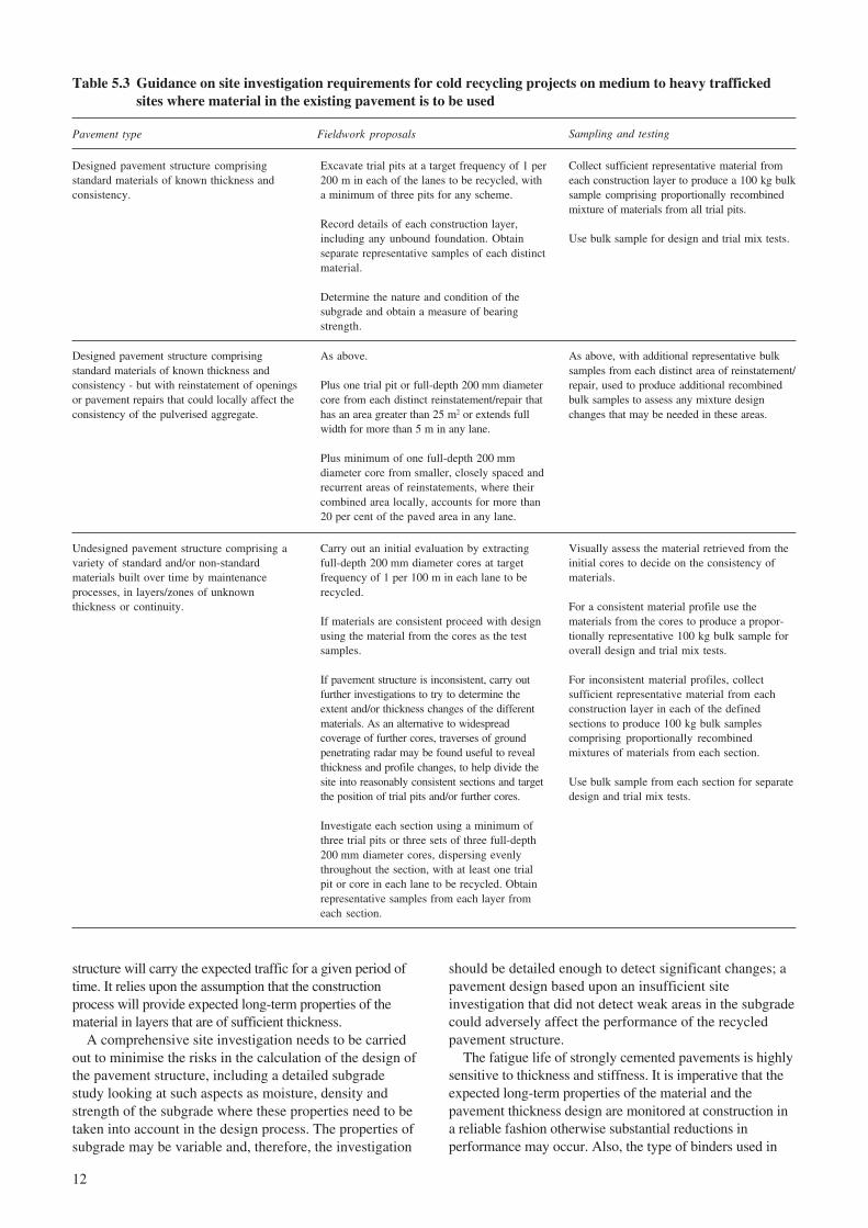
The method of sampling material from the existingpavement should consider the condition of that pavement.Milton and Earland (1999) gave advice based on samplingfrom trial pits and cores, and defined three basic conditionsof existing pavements with each condition associated witha level of uncertainty. As uncertainty increases, theoperations proposed for sampling material increase; theproposals are reproduced in Table 5.3.
5.6 Risk assessment
5.6.1 GeneralThe use of cold recycling techniques for pavementmaintenance involves particular risks that may not beencountered with other types of maintenance. This sectiongives guidance on the likely risks associated with coldrecycling so that consideration can be given to eithermitigating or accommodating these risks. The types of riskcovered in this document cannot be consideredcomprehensive. Site specific and material specific riskswill be encountered which will need to be considered priorto commencement of the works. These risks are oftendifficult to quantify in terms of any standard measure, buttheir consideration and equitable allocation will be vital ifthe cold recycling operations are to be completed to thesatisfaction of both contractor and client. Ignorance ofthese risks could lead to economic losses and/or a poorproduct and it is recommended that both the client as wellas the contractor should be aware of the risks associatedwith cold recycling at a particular site to prevent
unnecessary negative outcomes on maintenance schemes.Cold recycling is a developing industry that will have animportant role in road construction and maintenance; earlynegative relationships between clients and contractors dueto an insufficient comprehension of risk could seriouslyaffect the future of this industry.
In all types of construction work, even wherecomprehensive site evaluation has been carried out, therewill always remain those sites where unsuspectedsituations arise. However, for certain types of recyclingworks, such situations are more likely to play a part in thefinal outcome. Furthermore, for cold in situ recycling,there is an increased risk due to the variability of existingmaterials to be included in the finished works.
To offset this risk, greater understanding through ashared risk approach should be accepted for cold recyclingoperations. When existing pavement materials are beingused, both parties in the contract are given the opportunityto satisfy themselves and agree that these materials in thesections of the works defined by the contract, are capableof being recycled to form the main aggregate componentof the cold recycled mixture. For sites where ex situmaterials are to be laid, the contractor will usually supplythe main aggregate; for ex situ processes the risk is similarto other conventional material supplies. In general, theclient is responsible for ensuring that the contractingpartner has sufficient capability to obtain the mainaggregate and material components of sufficient quantityand quality so that the recycled mixture is capable of beingdesigned and produced to meet the specified end-productperformance requirements.
For sites where the existing pavement materials are to beused in the cold recycled material, the client is normallyexpected to organise and implement the site investigationworks separately, as part of the general design process forthe purposes of competitive tender arrangements. In thesecircumstances, if risk is to be shared, the investigationmust be comprehensive, and offer all potential contractorssuitable data for designing and programming theirindividual method of working, appropriate to the particularsite conditions.
The risks associated with any particular pavementrecycling scheme will need to be included in any whole-life cost analysis. Milton and Earland (1999) reported that‘experience to date has indicated that even where quitepessimistic projections for the service life of cold in siturecycled pavements are used, significant whole life costsavings are possible’.
Risks can be broadly classified into design risks andconstruction risks. The design risks are associated with thepavement design in terms of the expected performance onthe structure and mix design risks in terms of the expectedperformance on the recycled material. Construction risksare encountered during the preparation of the site forlaying recycled materials as well as the production,transporting and laying of recycled material.
5.6.2 Pavement design risksPavement design is the process of selecting materials andconstruction thicknesses in order to ensure that the pavement
12
structure will carry the expected traffic for a given period oftime. It relies upon the assumption that the constructionprocess will provide expected long-term properties of thematerial in layers that are of sufficient thickness.
A comprehensive site investigation needs to be carriedout to minimise the risks in the calculation of the design ofthe pavement structure, including a detailed subgradestudy looking at such aspects as moisture, density andstrength of the subgrade where these properties need to betaken into account in the design process. The properties ofsubgrade may be variable and, therefore, the investigation
should be detailed enough to detect significant changes; apavement design based upon an insufficient siteinvestigation that did not detect weak areas in the subgradecould adversely affect the performance of the recycledpavement structure.
The fatigue life of strongly cemented pavements is highlysensitive to thickness and stiffness. It is imperative that theexpected long-term properties of the material and thepavement thickness design are monitored at construction ina reliable fashion otherwise substantial reductions inperformance may occur. Also, the type of binders used in
Table 5.3 Guidance on site investigation requirements for cold recycling projects on medium to heavy traffickedsites where material in the existing pavement is to be used
Visually assess the material retrieved from theinitial cores to decide on the consistency ofmaterials.
For a consistent material profile use thematerials from the cores to produce a propor-tionally representative 100 kg bulk sample foroverall design and trial mix tests.
For inconsistent material profiles, collectsufficient representative material from eachconstruction layer in each of the definedsections to produce 100 kg bulk samplescomprising proportionally recombinedmixtures of materials from each section.
Use bulk sample from each section for separatedesign and trial mix tests.
Carry out an initial evaluation by extractingfull-depth 200 mm diameter cores at targetfrequency of 1 per 100 m in each lane to berecycled.
If materials are consistent proceed with designusing the material from the cores as the testsamples.
If pavement structure is inconsistent, carry outfurther investigations to try to determine theextent and/or thickness changes of the differentmaterials. As an alternative to widespreadcoverage of further cores, traverses of groundpenetrating radar may be found useful to revealthickness and profile changes, to help divide thesite into reasonably consistent sections and targetthe position of trial pits and/or further cores.
Investigate each section using a minimum ofthree trial pits or three sets of three full-depth200 mm diameter cores, dispersing evenlythroughout the section, with at least one trialpit or core in each lane to be recycled. Obtainrepresentative samples from each layer fromeach section.
Undesigned pavement structure comprising avariety of standard and/or non-standardmaterials built over time by maintenanceprocesses, in layers/zones of unknownthickness or continuity.
As above, with additional representative bulksamples from each distinct area of reinstatement/repair, used to produce additional recombinedbulk samples to assess any mixture designchanges that may be needed in these areas.
As above.
Plus one trial pit or full-depth 200 mm diametercore from each distinct reinstatement/repair thathas an area greater than 25 m2 or extends fullwidth for more than 5 m in any lane.
Plus minimum of one full-depth 200 mmdiameter core from smaller, closely spaced andrecurrent areas of reinstatements, where theircombined area locally, accounts for more than20 per cent of the paved area in any lane.
Designed pavement structure comprisingstandard materials of known thickness andconsistency - but with reinstatement of openingsor pavement repairs that could locally affect theconsistency of the pulverised aggregate.
Collect sufficient representative material fromeach construction layer to produce a 100 kg bulksample comprising proportionally recombinedmixture of materials from all trial pits.
Use bulk sample for design and trial mix tests.
Excavate trial pits at a target frequency of 1 per200 m in each of the lanes to be recycled, witha minimum of three pits for any scheme.
Record details of each construction layer,including any unbound foundation. Obtainseparate representative samples of each distinctmaterial.
Determine the nature and condition of thesubgrade and obtain a measure of bearingstrength.
Designed pavement structure comprisingstandard materials of known thickness andconsistency.
Sampling and testingFieldwork proposalsPavement type
13
the recycled mixture will affect the workability and settingtime. Such considerations are important in being able toachieve the specified layer density; density is the key factorin ensuring that the long-term performance that is assumedin the design is achieved.
The binder content will also influence the stiffness andstrength of the recycled mixture. An inadequate quantity ofbinder may lead to the material being susceptible tomoisture. Increasing the quantity of bituminous binderscould lead to premature deformation problems whileincreasing the quantity of quick setting cementitiousbinders increases likelihood of thermal cracking.
This guide contains pavement designs for sites with trafficcarrying up to 80 msa although the road trials on which thedesign guidance contained in this report was formed carried amaximum of 25 msa; therefore designs for heavily trafficroads are based upon extrapolations of existing knowledgeand they should therefore be used with caution.
5.6.3 Mix design risksThe mix design is principally performed as an essentialinput to the pavement design process. As such the risks formix design will have a significant impact on the risksassociated with pavement design.
The principle feedstock of aggregate for the mix designprocess should be the same feedstock of aggregate for thepermanent works. In some cases, sufficient aggregate fromthe same source as for the permanent works may beunavailable. Where aggregate is unavailable, the mixdesign should be performed on an aggregate as close as isreasonably possible to the aggregate in the permanentworks. A degree of caution should be applied to the resultsof this mix design process because these can be highlyinfluenced by the nature of the aggregate involved.
The recycled aggregates from existing roads containingmultiple layers may be more variable in quality and typethan those from a single layer because there is effectivelymore than one source. Where possible, the mix designstage should take into account this variability by varyingthe proportions of recycled aggregate from each layer.
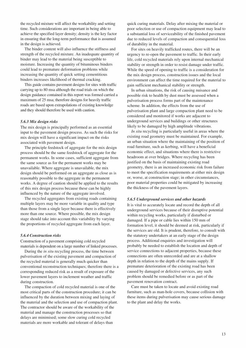
5.6.4 Construction risksConstruction of a pavement comprising cold recycledmaterials is dependent on a large number of linked processes.
During the in situ recycling process, the time betweenpulverisation of the existing pavement and compaction ofthe recycled material is generally much quicker thanconventional reconstruction techniques; therefore there is acorresponding reduced risk as a result of exposure of thelower pavement layers to inclement weather and trafficduring construction.
The compaction of cold recycled material is one of themost critical parts of the construction procedure; it can beinfluenced by the duration between mixing and laying ofthe material and the selection and use of compaction plant.The contractor should be aware of the workability of thematerial and manage the construction processes so thatdelays are minimised; some slow curing cold recycledmaterials are more workable and tolerant of delays than
quick curing materials. Delay after mixing the material orpoor selection or use of compaction equipment may lead toa substantial loss of serviceability of the finished pavementdue to reduced levels of compaction and consequential lossof durability in the material.
For sites on heavily trafficked routes, there will be anurgency to re-open the pavement to traffic. In their earlylife, cold recycled materials rely upon internal mechanicalstability or strength in order to resist damage under traffic.While the speed of opening to traffic is a consideration forthe mix design process, construction issues and the localenvironment can affect the time required for the material togain sufficient mechanical stability or strength.
In urban situations, the risk of causing nuisance andpossible risk to health by dust must be assessed when apulverisation process forms part of the maintenancescheme. In addition, the effects from the use ofpulverisation plant and large compaction plant need to beconsidered and monitored if works are adjacent tounderground services and buildings or other structureslikely to be damaged by high amplitude vibrations.
In situ recycling is particularly useful in areas where theexisting road geometry must be maintained. For example,an urban situation where the maintaining of the position ofroad furniture, such as kerbing, will have a beneficialeconomic effect, and situations where there is restrictiveheadroom at over bridges. Where recycling has beenjustified on the basis of maintaining existing roadgeometry, there is an increased economic risk from failureto meet the specification requirements at either mix designor, worse, at construction stage; in other circumstances,poor material properties could be mitigated by increasingthe thickness of the pavement layers.
5.6.5 Underground services and other hazardsIt is vital to accurately locate and record the depth of allunderground services because of their disruptive potentialwithin recycling works, particularly if disturbed ordamaged. If a pipe or cable lies within 150 mm offormation level, it should be deemed at risk, particularly ifthe services are old. It is prudent, therefore, to consult withthe statutory undertakers at an early stage of the designprocess. Additional enquiries and investigation willprobably be needed to establish the location and depth ofservice connections to adjacent properties, because theseconnections are often unrecorded and are at a shallowdepth in relation to the depth of the mains supply. Ifpremature deterioration of the existing road has beencaused by damaged or defective services, any suchproblem should be remedied before or as part of thepavement renovation contract.
Care must be taken to locate and avoid existing roadfurniture, such as man-hole covers, because collision withthese items during pulverisation may cause serious damageto the plant and delay the works.
14
6 Mix design of cold recycled materials
6.1 Aggregate
6.1.1 General requirements for aggregateThe aggregate for cold recycled material can come fromthe pulverised material from existing roads; alternatively,other approved aggregate types may be used from othersources.
The source and stock of the aggregate for recycling is akey factor in the decision about material composition andthe construction process. A fine grained aggregate may bemore suitable to hydraulic binders whilst certain types ofaggregate may prove incompatible with certain bituminousbinders. If it is possible to obtain an adequate volume ofaggregate from the road to be maintained by pulverisationof the existing material, then an in situ stabilisation processcould be favoured to an ex situ process.
6.1.2 GradingMany of the materials that could be considered to be coldrecycled materials are described under the umbrella ofEuropean (CEN) standards. It is, therefore, prudent toensure that the grading used for the specification to covercold recycled materials is consistent with all the materialsin the European standards that are likely to be required tobe covered by this guide. In particular, the sieve sizes shallbe consistent with European standards (which havereplaced previous BS sieve sizes in the UK).
Milton and Earland (1999) defined two grading zonesfor in situ stabilisation: Zone A and Zone B. Zone A is awell graded aggregate of nominal size 50 mm. Zone B is afiner grading than Zone A; materials graded to withinZone B were only permitted to be used if mix designtesting proved that this aggregate could be used to producea consistent cold recycled material.
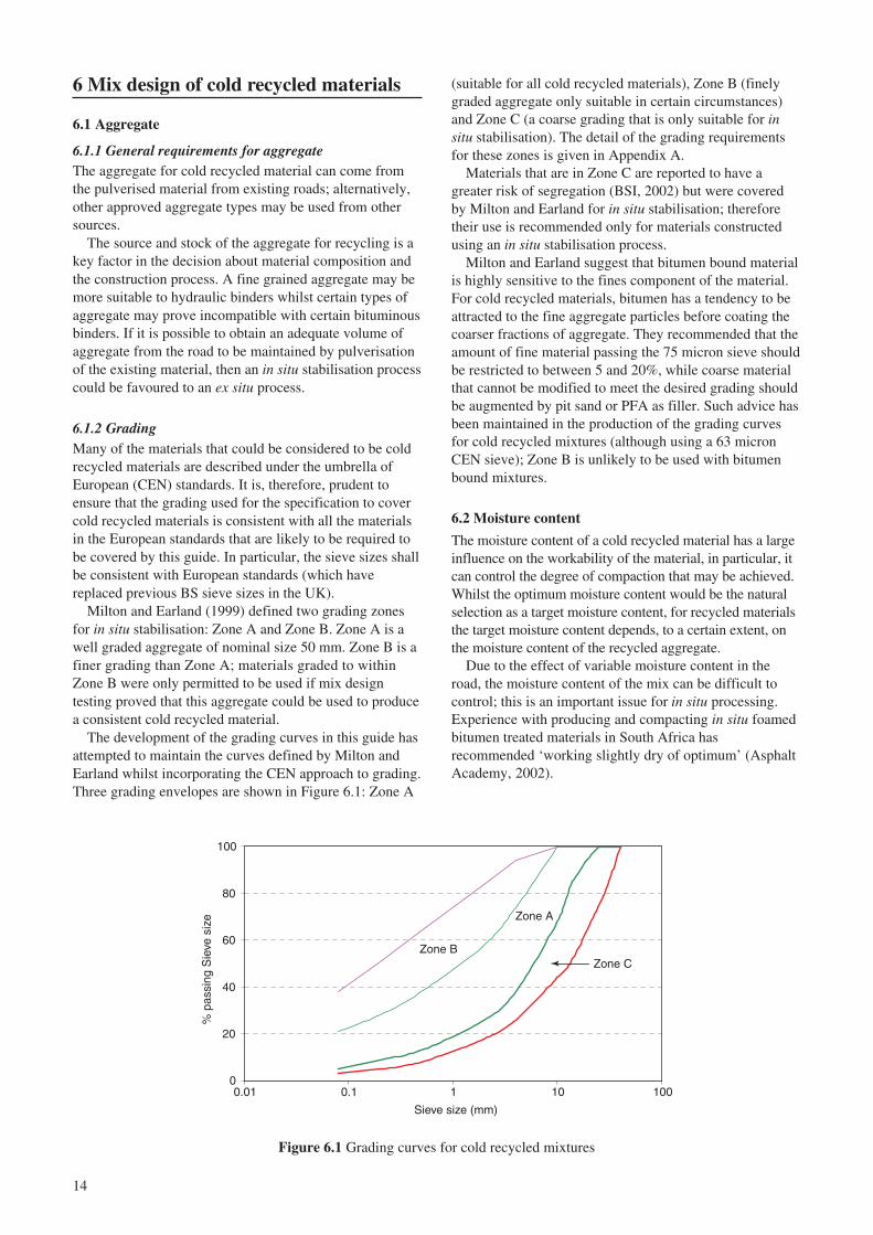
The development of the grading curves in this guide hasattempted to maintain the curves defined by Milton andEarland whilst incorporating the CEN approach to grading.Three grading envelopes are shown in Figure 6.1: Zone A
(suitable for all cold recycled materials), Zone B (finelygraded aggregate only suitable in certain circumstances)and Zone C (a coarse grading that is only suitable for insitu stabilisation). The detail of the grading requirementsfor these zones is given in Appendix A.
Materials that are in Zone C are reported to have agreater risk of segregation (BSI, 2002) but were coveredby Milton and Earland for in situ stabilisation; thereforetheir use is recommended only for materials constructedusing an in situ stabilisation process.
Milton and Earland suggest that bitumen bound materialis highly sensitive to the fines component of the material.For cold recycled materials, bitumen has a tendency to beattracted to the fine aggregate particles before coating thecoarser fractions of aggregate. They recommended that theamount of fine material passing the 75 micron sieve shouldbe restricted to between 5 and 20%, while coarse materialthat cannot be modified to meet the desired grading shouldbe augmented by pit sand or PFA as filler. Such advice hasbeen maintained in the production of the grading curvesfor cold recycled mixtures (although using a 63 micronCEN sieve); Zone B is unlikely to be used with bitumenbound mixtures.
6.2 Moisture content
The moisture content of a cold recycled material has a largeinfluence on the workability of the material, in particular, itcan control the degree of compaction that may be achieved.Whilst the optimum moisture content would be the naturalselection as a target moisture content, for recycled materialsthe target moisture content depends, to a certain extent, onthe moisture content of the recycled aggregate.
Due to the effect of variable moisture content in theroad, the moisture content of the mix can be difficult tocontrol; this is an important issue for in situ processing.Experience with producing and compacting in situ foamedbitumen treated materials in South Africa hasrecommended ‘working slightly dry of optimum’ (AsphaltAcademy, 2002).
0
20
40
60
80
100
0.01 0.1 1 10 100
Sieve size (mm)
% p
assi
ng S
ieve
siz
e
Zone C
Zone A
Zone B
Figure 6.1 Grading curves for cold recycled mixtures

15
6.3 Binding agents
6.3.1 Portland cementPortland cement is used to a lesser or greater degree inquick hydraulic (QH) materials and quick visco-elastic(QVE) materials; it is the key component that ensures thematerials are classified as quick curing.
The primary reason for the use of portland cement is toprovide a material that gains strength quickly at reasonablecost. Portland cement is a widely used road constructionbinding agent that can be used with a wide range ofaggregate types (including pulverised aggregates). It isrelatively tolerant of poor weather conditions because itcures quickly. It is also tolerant of some plastic or organicmaterial in the mixture.
Care should be taken in the design of materialscomprising portland cement. Whilst its use has clearadvantageous effects, mixtures with a high proportion ofcement will have a risk of thermal cracking.
Highways Agency and CEN specifications cover the useof cement bound aggregates; therefore, the use of mixturescomprising cement only may also be covered by otherspecifications providing the recycled aggregate also meetsthe particular requirements.
6.3.2 Other hydraulic bindersGranulated blast furnace slag (GBS) and ground granulatedblast furnace slag (GGBS) are by-products of the steelindustry. These materials are formed by rapid cooling ofmolten slag in water. GGBS is a fine material that can beused to substitute for a proportion of portland cement. GBSis a coarse material that could be used to form more of theaggregate skeleton of the mix; GBS can also be used as abinder if crushed in the presence of lime or sulphate.
Pulverised fuel ash (PFA) is a by-product from theburning of fuels in power stations and has been used inroad construction for many years. Its use in roadconstruction is currently covered by BS EN 14227-3 (BSI,2001) for fly ash bound material (FABM). It is possible touse lime with PFA and generate a strong binder throughpozzolanic reaction. It is a very fine grained material andcan be used to modify the amount of fine materials in themix. The use of PFA in preference to portland cementcreates a slower curing material in which diffuse crackingrather than large cracks develop. The long-term propertiesof a mixture containing PFA are likely to be similar to theequivalent mixture containing portland cement.
Unweathered 0/4 mm basic oxygen slag (BOS) is coveredby the specification; BOS is referred to as air-cooled steelslag (ASS) in CEN standards. These fines have a high freelime content and can perform many of the functions oftraditional lime. The proportion of BOS in the mix shouldbe restricted due to its expansion characteristics as thematerial hydrates to form a binder.
6.3.3 Foamed bitumenFoamed bitumen can be used with a variety of combinationsof other binders to produce fully-flexible pavementstructures. When used with other hydraulic binders, it couldbe viewed as a hybrid material: neither bituminous nor
hydraulic. Foamed bitumen binders are used to produceboth QVE and SVE material families; QVE material alsoincludes a proportion of portland cement.
Foamed bitumen is produced by the injection of 1 to 2%cold water with air into hot penetration grade bitumen.This process produces a high-volume, low viscosity fluidwith low surface tension; these properties enable thefoamed bitumen to coat a wide range of moist, coldrecycled aggregates.
The foaming temperature or water content has aninfluence on the expansion ratio (volumetric fluidexpansion after foaming) and bubble life; hightemperatures and water content increases the expansionratio but reduces bubble life. The choice of bitumen gradeis a compromise between foaming ability and stiffness;higher grade bitumen foams easily but has lower stiffness.
Materials bound with foamed bitumen, on its own orwith lime and PFA, are highly workable; they can bestock-piled or reworked if necessary up to 48 hours afterproduction. This feature indicates that the material is slowcuring; indeed, the long-term performance of thesematerials is reliant on the slow curing properties. Providedthat the material is sufficiently compacted, it can normallybe opened to a moderate degree of traffic after one day.
For an increased rate of curing, foamed bitumen can becombined with portland cement or other hydraulic binder.Increased curing may be required when the chosen binder/aggregate combination does not generate early-lifestiffness or when more demanding traffic conditions areencountered. The balance between foamed bitumen andsome hydraulic binders can be a compromise betweenearly life performance and the risk of thermal cracking.
6.3.4 Bitumen emulsionsBitumen emulsions are widely used in highway engineeringin a range of applications from tack coats to surfacedressings. They are also used as a bituminous binder forcold mixed materials including those in cold-mix recycling.
An emulsion is a system comprised of two immiscibleliquids, the one dispersed in the other, in the form of fineglobules or droplets. Bitumen emulsion is generally an oil-in-water type of emulsion in which the bitumen (the oil) isdispersed in water and held in suspension by means of oneor more emulsifying agents. This produces a low viscosityfluid at low temperatures that is suitable for coating coldrecycled aggregates. Compaction of the mixtureaccelerates the rate of development of cohesion bylaminating the bitumen globules and squeezing out thewater. Bitumen emulsion is readily combined withhydraulic binders but care should be taken to preventstripping problems by selecting an emulsion that it iscompatible with the aggregate.
The early life and long term properties of mixtures withbitumen emulsion are similar to those with foamed bitumen.
6.3.5 Other componentsOther components that are covered in this guide andspecification are principally lime, although the guide doesnot exclude any particular material components provided

16
that their value in road construction can be demonstrated.Lime (quick lime or hydrated lime) is used as both a
modifier and an activator of certain hydraulic components.Lime can create weak bonds between the recycledaggregate particles and can be used to reduce the plasticityof aggregate containing plastic or organic elements. Limecan improve the adhesion properties of the aggregate withbituminous binder. For some slow curing hydraulicbinders, lime is an activator for the other binding agents.
6.4 Guidance on the selection of materials
The scope of the design guide covers a range of materialtypes using a wide range of components. It is not the roleof the guide to advise on material composition; suchdecisions should be made based on the results of the mixdesign process and directed by local economic factors.However some general advice on cold recycled materialsis given, and advice on the applicability of differentcomponents is given in Section 6.3.
Guidance is, provided on the main features of the fourprincipal material families.
Quick curing materials achieve their optimal propertiesfairly early in their life. Such materials are suited tolocations where there are demands to open the pavementquickly and/or the traffic intensity will be high.
Slow curing materials offer increased workability and areduced risk of material performance being adverselyaffected by delays during construction. Hydraulicallybound, slow curing materials are thought to have a lowerrisk of reflection cracking than their quick curingcounterparts; naturally forming shrinkage cracks form in amore dispersed manner for slow curing materials than forquick curing materials. Slow curing materials can besuitable for locations where there is a traffic demand inearly life provided that the material has adequatemechanical stability.
Cold recycled materials can perform well under early-life trafficking provided that the materials are not damagedthrough permanent deformation or cracking. Permanentdeformation occurs where the traffic stresses exceed theinternal friction or strength of the material, when thematerial is said to be unstable. For some materials, cracksthat have occurred in early-life can be healed if significantcuring occurs after the cracks were initially formed. Quickcuring materials are at risk of damage during early-lifetrafficking due to cracking; deformation should beprevented by adequate stability. Slow curing materials areat risk of damage during early-life trafficking due todeformation; cracks that occur in early-life are likely to behealed during the slow curing process.
In the scope of this guide, the selection of either hydraulicor visco-elastic materials remains largely an economicdecision. However, aggregates whose grading contains ahigh proportion of fine material may be unsuitable for theproduction of bitumen bound cold recycled material.
6.5 Mix appraisal and design
6.5.1 GeneralMilton and Earland (1999) developed a mix design processbased upon an accelerated curing regime for in situstabilised material containing either cement or foamedbitumen. The approach proposed for cold recycledmaterials in this document allows the contractor morefreedom in which to conduct the mix design; it is,however, a requirement of the specification that the mixdesign stage is documented and used as part of thecompliance procedure in the permanent works.
Advice is supplied on the mix design process on thetreatment of the different families in the Notes forGuidance section of the specification. Therefore, it doesnot form part of the contract requirements but the endproduct requirements (which state that the work carried outin the mix design stage must be followed) will form part ofthe contract. The contractor has some freedom to choosethe method and detail of the mix design stage as agreedwith the client. The method of acquiring the results of themix design will need to be recorded for insertion into theMaterial Quality Plan (see Section 8.2).
The mix design stage should be as detailed as iseconomically feasible. The greater investment in the mixdesign stage, the less the risk at construction stage. Itshould be remembered that the law of diminishing returnsapplies, and the investment in the mix design stage must bebalanced with the risk of failure in the construction stage.For example, contracts on high profile routes for whichdelays in opening to traffic or repeat works are criticalwould justify a large investment in the mix design stage.
6.5.2 Material conditioning in the laboratoryThe design and specification of cold recycled material isbased upon the one year or long-term performance of thematerials. In order to obtain these estimates ofperformance in the laboratory, some form of sampleconditioning is required. When a material is described asquick-curing, it can develop stiffness or strength rapidlyand assurance of its long-term characteristics can beobtained in a relatively short time. In the UK, suchbehaviour has been traditionally exploited for specificationof portland cement bound materials.
Many materials cure at a slower rate and it is not possibleto provide assurance of the long-term properties of thematerials in the traditional manner. In order to obtain areliable estimate of the long-term properties, there shouldeither be a defined progression of performance from short tolong-term or an accelerated curing regime implemented thatreliably predicts the long term properties of the material. Thewide spectrum of materials that are covered in this guide doesnot allow for a defined progression of performance to beassumed; there is, therefore, a requirement to cure the materialin some accelerated manner to provide a more reliableassurance of its long-term properties.
Accelerated curing is achieved by raising thetemperature of the environment surrounding the materialto increase the rate of chemical reaction in the sample.Curing at elevated temperatures can affect the type of
17
chemical reaction in the sample and it is, therefore,preferable to use a temperature for curing that is as close aspossible to the temperature that would be encountered inthe pavement. Milton and Earland advocated a curingregime of 60 °C for 72 hours. This curing regime wasundertaken at a far higher temperature than average in situpavement temperatures and may be considered unrealistic.
For this design guide, a low temperature regime forsample conditioning has been sought wherever possible.The specification does not prescribe the method to use butsimply advises on the most applicable regime in the Notesfor Guidance. A summary of the advised conditioningregimes is shown in Table 6.1. A curing regime for SVEmaterial is provided only when it contains a pozzolaniccomponent; otherwise a high curing temperature isrequired to generate some form of curing in early life.Curing at such temperatures is not encouraged forprediction of long-term performance, but may be suitableonly for establishing a provisional mix design.
This design guide includes mutually exclusive methodsto perform pavement design for both situations.
7.2 Pavement design for full depth cold recycling
7.2.1 BackgroundMilton and Earland (1999) produced design curves for insitu cold recycled material based upon a limited set of trialdata. These curves were developed in isolation due to thesmall number of possible constructions considered. Thisdesign guide extends these curves to cover a wide range ofrecycled pavement materials using both in situ and ex situconstruction techniques.
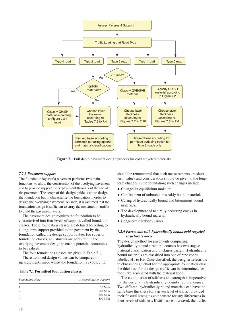
The design of pavements comprising Cold RecycledMaterial follows the Versatile Pavement Designmethodology that is currently under development by theHighways Agency (Nunn, 2004). This method uses asingle pool of input data from which separate designcriteria are applied depending on whether the basecomprises a hydraulically bound or bituminous boundmaterial. Figure 7.1 gives an illustrative view of thepavement design process for cold recycled materials.
7.2.2 DefinitionsIn the context of structural maintenance of highwaypavements using cold recycling, whilst carrying out thesame function, a standard pavement layer may beconstructed significantly different to that of the same layerin a new pavement. Therefore, the broader definitionsapplicable to this design guide are:
Subgrade: Underlying natural soil or rock. However, inthe situations where the subgrade is weak or there isinsufficient depth to the existing pavement, the upper layerof the subgrade may be stabilised using the in siturecycling technique and incorporated as part thefoundation platform.
Formation level: Immediately below the sub-base layerand at the top of the subgrade or capping layer.
Foundation: The support to the overlying pavementlayers that serves as a platform to construct the structuralcourse. It includes the sub-base, subgrade and the cappinglayer if required. For maintenance purposes, this layer willnormally comprise the undisturbed lower sections of theexisting pavement. In situations where there is insufficientdepth of existing pavement to satisfy the current design orwhere other circumstances dictate, this platform may beconstructed, in part or whole, using cold recycled material.
Structural course: The main stress distribution layerwithin the pavement whose thickness is dependent onstiffness of the material itself, stiffness of the underlyingstructure and the anticipated traffic loading. This layer willnormally comprise cold recycled material, but where thereis insufficient depth of existing pavement and the in siturecycled material is used to form the foundation platform,it may comprise in part or whole, new plant mixedmaterial. This layer is often called the base.
Surfacing: The upper layer or layers of the road,designed to provide an even surface with a high resistanceto deformation and an adequate resistance to skidding.
Table 6.1 Laboratory conditioning regimes and factorsto relate to long-term performance
Temperature Duration Long-termFamily (°C) (days) factor
QH 20 28 1.2SH 40 28 1.0QVE 20 28 1.2QVE* 40 28 1.0SVE – – –SVE* 40 28 1.0
* For materials containing a pozzolanic binder.
The long-term factors shown in Table 6.1 are used toprovide an estimate of the performance of cold recycledmaterials after approximately one year. The pavementdesigns given in Section 7 of this guide are based upon theproperties of cold recycled material at one year. Therefore,the conditioning regimes described in Table 6.1 can beused with an appropriate laboratory test procedure to giveconfidence, at an early stage, that the properties assumedto design the pavement are likely to be achieved. The long-term factors are conservative but other factors may be usedwith appropriate supporting evidence.
7 Pavement design using cold recycledmaterials
7.1 Full depth or partial depth pavement design
Cold recycled materials can be utilised in a pavementstructure in two ways:
� The cold recycled material forms the layer immediatelyabove the foundation and is covered by a bituminoussurfacing.
� Bitumen bound cold recycled material can be used as asubstitute for conventional hot mix material for inlaytreatments where a significant proportion of the existingpavement remains to form part of the rehabilitatedpavement.
18
7.2.3 Pavement supportThe foundation layer of a pavement performs two mainfunctions: to allow the construction of the overlying pavementand to provide support to the pavement throughout the life ofthe pavement. The scope of this design guide is not to designthe foundation but to characterise the foundation in order todesign the overlying pavement. As such, it is assumed that thefoundation design is sufficient to carry the construction trafficto build the pavement layers.
The pavement design requires the foundation to becharacterised into four levels of support, called foundationclasses. These foundation classes are defined according toa long-term support provided to the pavement by thefoundation called the design support value. For superiorfoundation classes, adjustments are permitted in theoverlying pavement design to enable potential economiesto be realised.
The four foundations classes are given in Table 7.1.These assumed design values can be compared to
measurements made whilst the foundation is exposed. It
should be remembered that such measurements are short-term values and consideration should be given to the long-term changes in the foundation; such changes include:
� Changes in equilibrium moisture.
� Confinement of unbound or weakly bound material.
� Curing of hydraulically bound and bituminous boundmaterials.
� The development of naturally occurring cracks inhydraulically bound material.
� Long-term durability issues
7.2.4 Pavements with hydraulically bound cold recycledstructural course
The design method for pavements comprisinghydraulically bound structural courses has two stages:material classification and thickness design. Hydraulicallybound materials are classified into one of nine zoneslabelled H1 to H9. Once classified, the designer selects thethickness design chart for the appropriate foundation class;the thickness for the design traffic can be determined forthe curve associated with the material zone.
The combination of stiffness and strength is imperativefor the design of a hydraulically bound structural course.Two different hydraulically bound materials can have thesame base thickness for a given level of traffic, providedtheir flexural strengths compensate for any differences intheir levels of stiffness. If stiffness is increased, the traffic
Table 7.1 Permitted foundation classes
Foundation class Assumed design support
1 50 MPa2 100 MPa3 200 MPa4 400 MPa
Figure 7.1 Full depth pavement design process for cold recycled materials
Type 4 road Type 3 road Type 2 road Type 1 road Type 0 road
Classify QH/SH material according
to Figure 7.2
Classify QVE/SVE material
Choose layer thickness
according to Figures 7.3 to 7.6
Choose layer thickness
according to Figures 7.7 to 7.10
Revised base according to permitted surfacing options and material classifications
Choose layer thickness
according to Tables 7.3 to 7.4
Revised base according to permitted surfacing option for
Type 2 roads only
Traffic Loading and Road Type
Assess Pavement Support
< 5 msa?Yes No
QH/SH materials?Yes
No
Classify QH/SH material according
to Figure 7.2 if used
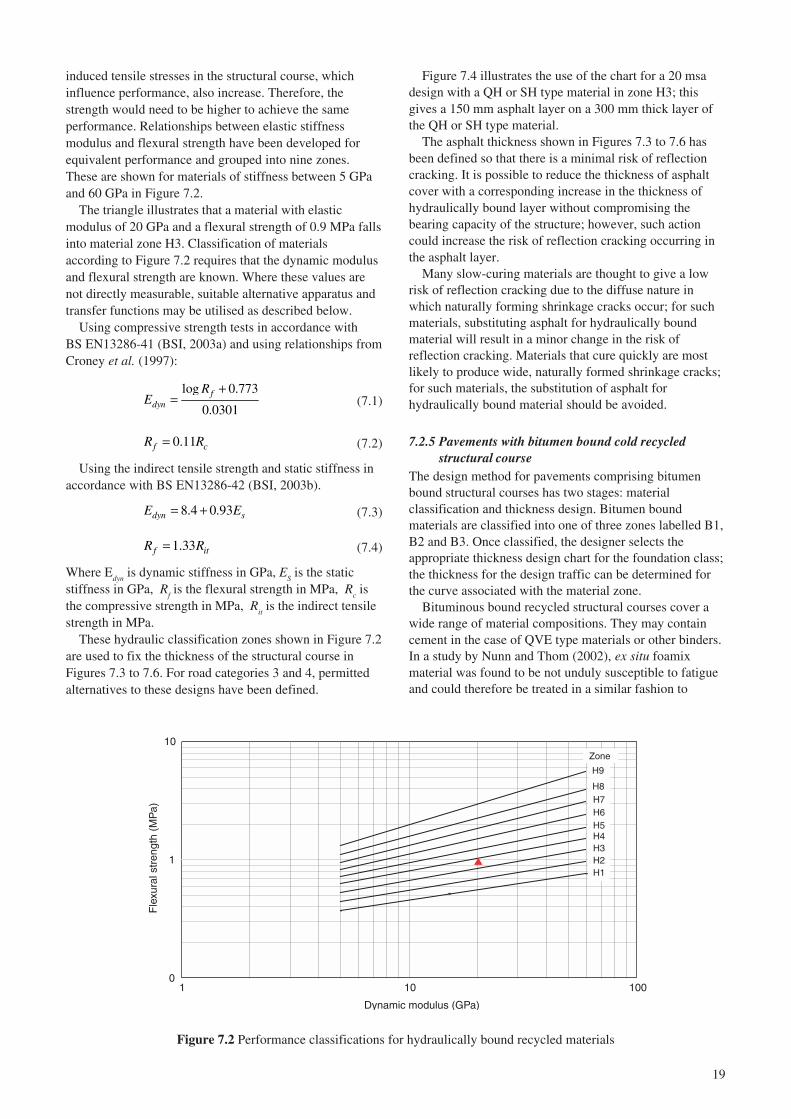
19
induced tensile stresses in the structural course, whichinfluence performance, also increase. Therefore, thestrength would need to be higher to achieve the sameperformance. Relationships between elastic stiffnessmodulus and flexural strength have been developed forequivalent performance and grouped into nine zones.These are shown for materials of stiffness between 5 GPaand 60 GPa in Figure 7.2.
The triangle illustrates that a material with elasticmodulus of 20 GPa and a flexural strength of 0.9 MPa fallsinto material zone H3. Classification of materialsaccording to Figure 7.2 requires that the dynamic modulusand flexural strength are known. Where these values arenot directly measurable, suitable alternative apparatus andtransfer functions may be utilised as described below.
Using compressive strength tests in accordance withBS EN13286-41 (BSI, 2003a) and using relationships fromCroney et al. (1997):
log 0.773
0.0301f
dyn
RE
+= (7.1)
0.11f cR R= (7.2)
Using the indirect tensile strength and static stiffness inaccordance with BS EN13286-42 (BSI, 2003b).
8.4 0.93dyn sE E= + (7.3)
1.33f itR R= (7.4)
Where Edyn
is dynamic stiffness in GPa, ES is the static
stiffness in GPa, Rf is the flexural strength in MPa, R
c is
the compressive strength in MPa, Rit is the indirect tensile
strength in MPa.These hydraulic classification zones shown in Figure 7.2
are used to fix the thickness of the structural course inFigures 7.3 to 7.6. For road categories 3 and 4, permittedalternatives to these designs have been defined.
Figure 7.4 illustrates the use of the chart for a 20 msadesign with a QH or SH type material in zone H3; thisgives a 150 mm asphalt layer on a 300 mm thick layer ofthe QH or SH type material.
The asphalt thickness shown in Figures 7.3 to 7.6 hasbeen defined so that there is a minimal risk of reflectioncracking. It is possible to reduce the thickness of asphaltcover with a corresponding increase in the thickness ofhydraulically bound layer without compromising thebearing capacity of the structure; however, such actioncould increase the risk of reflection cracking occurring inthe asphalt layer.
Many slow-curing materials are thought to give a lowrisk of reflection cracking due to the diffuse nature inwhich naturally forming shrinkage cracks occur; for suchmaterials, substituting asphalt for hydraulically boundmaterial will result in a minor change in the risk ofreflection cracking. Materials that cure quickly are mostlikely to produce wide, naturally formed shrinkage cracks;for such materials, the substitution of asphalt forhydraulically bound material should be avoided.
7.2.5 Pavements with bitumen bound cold recycledstructural course
The design method for pavements comprising bitumenbound structural courses has two stages: materialclassification and thickness design. Bitumen boundmaterials are classified into one of three zones labelled B1,B2 and B3. Once classified, the designer selects theappropriate thickness design chart for the foundation class;the thickness for the design traffic can be determined forthe curve associated with the material zone.
Bituminous bound recycled structural courses cover awide range of material compositions. They may containcement in the case of QVE type materials or other binders.In a study by Nunn and Thom (2002), ex situ foamixmaterial was found to be not unduly susceptible to fatigueand could therefore be treated in a similar fashion to
Figure 7.2 Performance classifications for hydraulically bound recycled materials
0
1
10
1 10 100
Dynamic modulus (GPa)
Fle
xura
l str
engt
h (M
Pa)
Zone
H9
H7
H1H2H3H4H5H6
H8

20
Figure 7.3 Design thicknesses for road Type 2 and superior roads with a Class 1 foundation
Figure 7.4 Design thicknesses for road Type 2 and superior roads with a Class 2 foundation
Figure 7.5 Design thicknesses for road Type 2 and superior roads with a Class 3 foundation
50
100
150
200
Asp
halt
Laye
r (m
m)
100
150
200
250
300
350
400
450
500
1 10 100Cumulative Traffic (msa)
Hyd
raul
ical
ly b
ound
bas
e (m
m)
H1
H9
H4
H5
H6
H7
H8
Zone
H2
H3
50
100
150
200
Asp
halt
laye
r (m
m)
100
150
200
250
300
350
400
450
500
1 10 100
Cumulative Traffic (msa)
Hyd
raul
ical
ly b
ound
bas
e (m
m) H1
H9
H4
H5
H6
H7H8
H2
H3
Zone
50
100
150
200
Asp
halt
laye
r (m
m)
100
150
200
250
300
350
400
450
500
1 10 100
Cumulative Traffic (msa)
Hyd
raul
ical
ly b
ound
bas
e (m
m)
H1
H4
H5
H6H7
H8,9
H2
H3
Zone
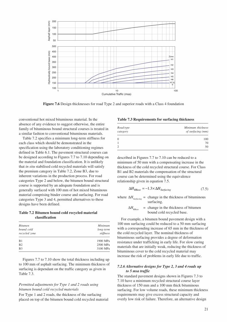
21
50
100
150
200
Asp
halt
laye
r (m
m)
100
150
200
250
300
350
400
450
500
1 10 100
Cumulative Traffic (msa)
Hyd
raul
ical
ly b
ound
bas
e (m
m)
H1
H4
H5H6
H7,8,9
H2
H3
Zone
Figure 7.6 Design thicknesses for road Type 2 and superior roads with a Class 4 foundation
Table 7.2 Bitumen bound cold recycled materialclassification
Bitumen Minimumbound cold long-termrecycled zone stiffness
B1 1900 MPaB2 2500 MPaB3 3100 MPa
Table 7.3 Requirements for surfacing thickness
Road type Minimum thicknesscategory of surfacing (mm)
0 1001 702 50
conventional hot mixed bituminous material. In theabsence of any evidence to suggest otherwise, the entirefamily of bituminous bound structural courses is treated ina similar fashion to conventional bituminous materials.
Table 7.2 specifies a minimum long-term stiffness foreach class which should be demonstrated in thespecification using the laboratory conditioning regimesdefined in Table 6.1. The pavement structural courses canbe designed according to Figures 7.7 to 7.10 depending onthe material and foundation classification. It is unlikelythat in situ stabilised cold recycled materials will satisfythe premium category in Table 7.2, Zone B3, due toinherent variations in the production process. For roadcategories Type 2 and below, the bitumen bound structuralcourse is supported by an adequate foundation and isgenerally surfaced with 100 mm of hot mixed bituminousmaterial comprising binder course and surfacing. For roadcategories Type 3 and 4, permitted alternatives to thesedesigns have been defined.
Figures 7.7 to 7.10 show the total thickness including upto 100 mm of asphalt surfacing. The minimum thickness ofsurfacing is dependant on the traffic category as given inTable 7.3.
Permitted adjustments for Type 1 and 2 roads usingbitumen bound cold recycled materials
For Type 1 and 2 roads, the thickness of the surfacingplaced on top of the bitumen bound cold recycled material
described in Figures 7.7 to 7.10 can be reduced to aminimum of 50 mm with a compensating increase in thethickness of the cold recycled structural course. For ClassB1 and B2 materials the compensation of the structuralcourse can be determined using the equivalencerelationship given in equation 7.5.
1.3RBase SurfacingH H∆ = − × ∆ (7.5)
where ∆HSurfacing
= change in the thickness of bituminoussurfacing.
∆HRBase
= change in the thickness of bitumenbound cold recycled base.
For example, a bitumen bound pavement design with a100 mm surfacing could be reduced to a 50 mm surfacingwith a corresponding increase of 65 mm in the thickness ofthe cold recycled layer. The nominal thickness ofbituminous surfacing provides a degree of deformationresistance under trafficking in early life. For slow curingmaterials that are initially weak, reducing the thickness ofbituminous cover to the cold recycled material mayincrease the risk of problems in early life due to traffic.
7.2.6 Alternative designs for Type 2, 3 and 4 roads upto 5 msa traffic
The standard pavement designs shown in Figures 7.3 to7.10 have a minimum recycled structural course layerthickness of 150 mm and a 100 mm thick bituminoussurfacing. For low volume roads, these minimum thicknessrequirements may give excess structural capacity andoverly low risk of failure. Therefore, an alternative design

22
Figure 7.7 Design curves for bitumen bound cold recycled material (Foundation Class 1)
Figure 7.8 Design curves for bitumen bound cold recycled material (Foundation Class 2)
Figure 7.9 Design curves for bitumen bound cold recycled material (Foundation Class 3)
100
150
200
250
300
350
400
450
500
1 10 100
Traffic (msa)
Tota
l thi
ckne
ss o
f bou
nd la
yer
(mm
)
Zone B1
Zone B2
Zone B3
These designs include up to 100 mmasphalt surfacing as shown in Table 7.3
100
150
200
250
300
350
400
450
500
1 10 100
Traffic (msa)
Tota
l thi
ckne
ss o
f bou
nd la
yer
(mm
)
Zone B1
Zone B2
Zone B3
These designs include up to 100 mmasphalt surfacing as shown in Table 7.3
100
150
200
250
300
350
400
450
500
1 10 100
Traffic (msa)
Tota
l thi
ckne
ss o
f bou
nd la
yer
(mm
)
Zone B1
Zone B2
Zone B3
These designs include up to 100 mmasphalt surfacing as shown in Table 7.3

23
Figure 7.10 Design curves for bitumen bound cold recycled material (Foundation Class 4)
Table 7.4 Thickness of pavements using cold recycled materials as the combined structural course and foundationplatform in roads up to 5 msa
Thickness of cold recycled material (mm)
Binder type Hydraulically bound material
Type 2 road Type 3 road Type 4 road
Surfacing Surface Surface Surfacethickness (mm) dressing 40 100 dressing 40 100 dressing 40 100
Subgrade CBR (%)<2 n/r n/r n/r n/r n/r n/r n/r n/r n/r2-4 n/r 300 240 280 240 180 240 200 1505-7 n/r 280 220 260 220 160 220 180 1508-14 n/r 270 200 240 200 150 200 160 150>15 n/r 250 200 220 180 150 190 150 150
Binder type Bitumen bound material
Type 2 road Type 3 road Type 4 road
Surfacing Surface Surface Surfacethickness (mm) dressing 40 100 dressing 40 100 dressing 40 100
Subgrade CBR (%)<2 n/r n/r n/r n/r n/r n/r n/r n/r n/r2-4 n/r n/r n/r n/r 310(n/r) 250 320(n/r) 280 1955-7 n/r n/r n/r 330 290 230 300 260 1858-14 n/r n/r 300 315 275 215 285 245 160>15 n/r n/r 270 285 245 185 255 215 150
n/r: not recommended
approach for these roads is provided for roads with trafficless than 5 msa that will take advantage of a reducedrequirement for structural capacity and improve theeconomic viability of cold recycling.
Potter (1996) proposed designs for pavementscontaining cold in situ recycled materials for Type 2, 3 and4 roads. These low volume roads can be designed from theformation level with the structural contribution of the sub-base layer incorporated into an increased thickness ofrecycled structural course. There is no evidence to suggestthat these designs have not performed well and, therefore,
they have been maintained for all cold recycled materialscovered within this guide. These designs cover a range ofsurfacing options from surface dressing up to a cover of100 mm of asphalt surfacing.
Table 7.4 shows the thickness design of cold recycledstructural courses (incorporating the foundation platform).Alternative surfacing options allow for a reduction in thethickness of the cold recycled layer for a compensatingincrease in surfacing thickness.
These designs incorporating structural and foundationlayers were proposed assuming minimum performance
100
150
200
250
300
350
400
450
500
1 10 100
Traffic (msa)
Tota
l thi
ckne
ss o
f bou
nd la
yer
(mm
)
Zone B1
Zone B2
Zone B3
These designs include up to 100 mmasphalt surfacing as shown in Table 7.3

24
requirements for strength and stiffness; the equivalentminimum requirements are:
� Hydraulically bound material should be Type H5 orsuperior (Figure 7.2).
� Bitumen bound material should be Type B1 or superior(Table 7.2).
For hydraulically bound materials classed as H1, H2, H3or H4 the following adjustments in Table 7.5 can beapplied to the thickness of the materials in Table 7.4. Forexample, for a Type 3 road with subgrade CBR of between5 and 7%, a hydraulically bound material of class H4 witha layer thickness of 250 mm (220 × 1.13) with a 40 mmsurfacing can be used. Some combinations of materialquality and subgrade strength will produce thick layers; forthese combinations, the standard approach given in Section7.2.2 can be used.
is likely to produce overly thick pavement layers. Thefollowing methodology attempts to account for thestructural value of the existing ‘good quality’ bituminousmaterial together with the cold recycled layers.
The design methodology described is based upon long-term design stiffness for in situ and ex situ cold recycledmaterials. The method of equivalent thickness (Ullidtz,1987) can be used to compare the adequacy of arehabilitated layer using cold recycled material comparedwith that of a conventional hot mix material, such as a densebitumen macadam, using a structural equivalence number(SEN). The structural equivalence number is calculatedusing Equation 7.6 using the parameters given in Table 7.6.
13
i ii
SEN h E=∑ (7.6)
Where i = Layer identifier.h = Thickness of the layer (m).E = Design stiffness of the layer (MPa).
Table 7.5 Adjustments for hydraulically boundmaterials H1 to H4
Material Thickness adjustment
H1 1.66H2 1.45H3 1.28H4 1.13H5 or superior 1.0
Table 7.6 Long-term design stiffness for bitumen boundmaterial
Material description Design stiffness (MPa)
Surface course 2000Cold recycled material Class B1 1900Cold recycled material Class B2 2500Cold recycled material Class B3 3100New hot-mixed asphalt 3100Existing asphalt base material* 3100
* The design stiffness may be augmented by values obtained fromlaboratory testing.
Table 7.7 Minimum required SEN for partial depthrecycling
MinimumMinimum surfacing
Road type Minimum SEN thicknesscategory SEN (CBM base) (mm)
0 5.7 2.6 1001 4.8 2.4 702 4.0 1.9 503 3.2 1.2 Surface dressing4 2.5 0.2 Surface dressing
All permitted alternatives are subject to a 150 mmminimum layer thickness of cold recycled material; amaximum thickness of 300 mm is also recommended.
Designs are not provided for weak subgrade conditionsthat may give inadequate resistance to damage byconstruction traffic or may not provide the necessarysupport for adequate compaction of the cold recycledlayer. Methods for dealing with weak subgrade conditionscan be found in the Design Manual for Roads and Bridges(DMRB 7.2.2).
7.3 Treatment design for partial depth cold recycling
7.3.1 Design methodologySection 7.2 covered pavement designs comprising cold in siturecycled materials for the pavement layers from thefoundation upwards. Such designs were applicable to newconstruction and full-depth reconstruction. Some maintenancetreatments for fully-flexible roads do not require the completereplacement of the pavement layers particularly for thickbituminous roads and, therefore, an alternative treatmentdesign procedure is proposed that could still utilise significantamounts of cold recycled materials.
A conservative approach would be to design thepavement using the approach described in Section 7.2. Theapproach would ensure that the total thickness of thepavement is maintained as shown in Figures 7.7 to 7.10and any bituminous material remaining in good conditionwould then add assurance. Such an approach would beapplicable when the remaining mature bituminous layerforms the minority of the rehabilitated pavement.
When the thickness of remaining mature bituminousmaterial is significant, the method described in Section 7.2
Using standard designs for full depth constructionsusing conventional hot mix material, the criterion for theminimum SEN for designing a partial depth treatmentcomprising cold recycled materials is given in Table 7.7. Aminimum thickness of asphalt surfacing is required toconcur with the requirements for full depth recyclingoptions shown in Figures 7.7 to 7.10. For cases where aCBM base layer exists, alternative SEN are given; forthese cases, the structural contribution of the CBM layer isnot accounted for in the SEN calculations.
The minimum requirements for the SEN shown inTable 7.7 have been deduced from the curves given byPowell et al. (1984); these curves were constructed using an85% probability of survival. Powell et al. (1984)

25
acknowledge that for less important roads, a lowerprobability appropriate to the performance of the roadshould be used. Table 7.8 gives factors that can be appliedto the SEN for different probabilities of survival. For a 70%probability of survival, the minimum SEN requirement for aRoad Type Category 2 will be 4.0 × 0.9 = 3.6.
Figure 7.11 shows three partial depth recyclingsolutions using each of the bitumen bound cold recycledmaterial classes: B1, B2 and B3. For the solution usingClass B1 material, the uppermost 170 mm of theexisting pavement could be in situ stabilised and a thinsurfacing is laid on top of the recycled material;alternatively the existing pavement material could beremoved and ex situ cold recycled materials used. Usingclass B2 and B3 materials will result in reductions in theoverall pavement thickness.
Example 2:
In this example the existing asphalt pavement is 320 mmthick and the pavement is to be upgraded by partial depthcold recycled material to carry design traffic of 30 msa.The deterioration in the existing structure requires thatonly the lower most 150 mm of the existing pavementstructure be retained after maintenance.
Figure 7.12 shows three partial depth recycling solutionsusing each of the bitumen bound cold recycled materialclasses: B1, B2 and B3. For the solution using Class B1material, the upper most 170 mm of the existing pavementcould be in situ stabilised and a bituminous surfacing ofthickness 100 mm (50 mm surface course and 50 mmasphalt binder course) is laid on top of the recycledmaterial; alternatively, the existing pavement materialcould be removed and ex situ cold recycled materials used.Using class B2 and B3 materials will result in reductions inthe overall pavement thickness.
8 Specification of cold recycled materials
8.1 General
Specifications for the production of cold recycled materialshas been covered in the Specification for Highway Works(MCHW1) Series 900 and 1000 for a number of years.These specifications have covered the production ofcement bound and foamed bitumen bound recycledmaterial using an in situ stabilisation process. In recentyears, ex situ or plant mixed cold recycled material
Table 7.8 Factors to be applied to SEN requirements
Probability of survival Factor
85% 1.070% 0.960% 0.8
DesignThickness stiffness
Layer (m) (MPa) 31
ii Eh
Surface course 0.050 2000 0.6Cold recycled material Class B2 0.140 2500 2.1Existing asphalt base material 0.1 3100 1.5
SEN = 0.44 + 2.1 + 1.46 = 4.0
7.3.2 Examples of treatment design using partial depthcold recycling
The following examples of partial depth recycling arepresented. Example 1 is a pavement that is maintained toremedy deterioration and to provide the same structuralcapacity at the existing pavement. Example 2 is apavement whose structural capacity is to be upgraded bypartial depth recycling.
Example 1:An existing asphalt pavement of 270 mm comprising aDBM type material and hot rolled asphalt surfacing is tobe maintained by partial depth recycling to carry a designtraffic of 5 msa. The existing pavement contained somedeterioration in the asphalt layers and the lower most100 mm of the existing pavement is in a good condition.
A derivation of the necessary calculation using Class B2materials is as follows:
Figure 7.11 Example of an existing structure maintained by partial depth recycling
0
0.05
0.1
0.15
0.2
0.25
0.3
0.35
Existingstructure
Recycledstructure
using Class 1Material
Recycledstructure
using Class 2Material
Recycledstructure
using Class 3Material
Thi
ckne
ss (
mm
) Existing surface course
New surface course
Class 3
Class 2
Class 1
Existing base
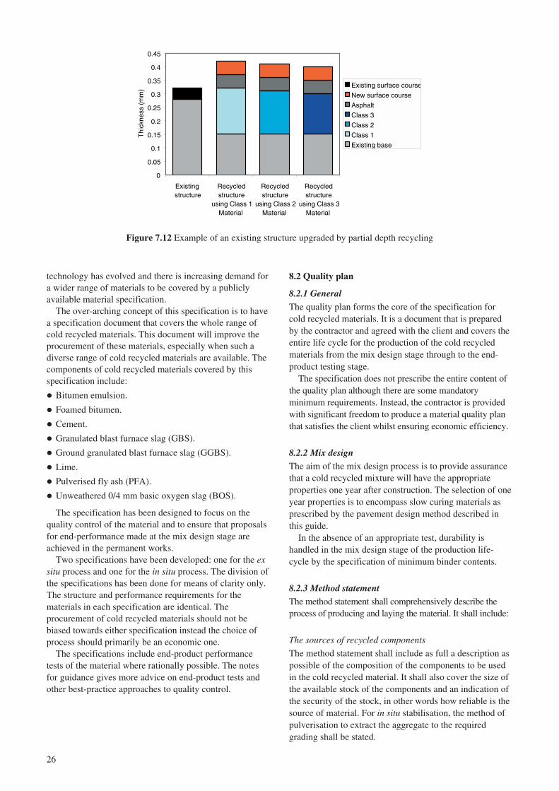
26
technology has evolved and there is increasing demand fora wider range of materials to be covered by a publiclyavailable material specification.
The over-arching concept of this specification is to havea specification document that covers the whole range ofcold recycled materials. This document will improve theprocurement of these materials, especially when such adiverse range of cold recycled materials are available. Thecomponents of cold recycled materials covered by thisspecification include:
� Bitumen emulsion.
� Foamed bitumen.
� Cement.
� Granulated blast furnace slag (GBS).
� Ground granulated blast furnace slag (GGBS).
� Lime.
� Pulverised fly ash (PFA).
� Unweathered 0/4 mm basic oxygen slag (BOS).
The specification has been designed to focus on thequality control of the material and to ensure that proposalsfor end-performance made at the mix design stage areachieved in the permanent works.
Two specifications have been developed: one for the exsitu process and one for the in situ process. The division ofthe specifications has been done for means of clarity only.The structure and performance requirements for thematerials in each specification are identical. Theprocurement of cold recycled materials should not bebiased towards either specification instead the choice ofprocess should primarily be an economic one.
The specifications include end-product performancetests of the material where rationally possible. The notesfor guidance gives more advice on end-product tests andother best-practice approaches to quality control.
8.2 Quality plan
8.2.1 GeneralThe quality plan forms the core of the specification forcold recycled materials. It is a document that is preparedby the contractor and agreed with the client and covers theentire life cycle for the production of the cold recycledmaterials from the mix design stage through to the end-product testing stage.
The specification does not prescribe the entire content ofthe quality plan although there are some mandatoryminimum requirements. Instead, the contractor is providedwith significant freedom to produce a material quality planthat satisfies the client whilst ensuring economic efficiency.
8.2.2 Mix designThe aim of the mix design process is to provide assurancethat a cold recycled mixture will have the appropriateproperties one year after construction. The selection of oneyear properties is to encompass slow curing materials asprescribed by the pavement design method described inthis guide.
In the absence of an appropriate test, durability ishandled in the mix design stage of the production life-cycle by the specification of minimum binder contents.
8.2.3 Method statementThe method statement shall comprehensively describe theprocess of producing and laying the material. It shall include:
The sources of recycled components
The method statement shall include as full a description aspossible of the composition of the components to be usedin the cold recycled material. It shall also cover the size ofthe available stock of the components and an indication ofthe security of the stock, in other words how reliable is thesource of material. For in situ stabilisation, the method ofpulverisation to extract the aggregate to the requiredgrading shall be stated.
Figure 7.12 Example of an existing structure upgraded by partial depth recycling
0
0.05
0.1
0.15
0.2
0.25
0.3
0.35
0.4
0.45
Existingstructure
Recycledstructure
using Class 1Material
Recycledstructure
using Class 2Material
Recycledstructure
using Class 3Material
Thi
ckne
ss (
mm
)
Existing surface course
New surface course
Asphalt
Class 3
Class 2
Class 1
Existing base

27
Production
The method of production of the cold recycled materialsshall be described in detail. The storage of the componentmaterials may be important to maintain the quality of theproduct material. The plant used for mixing thecomponents shall be detailed including the method ofaddition of the components and the methods forcontrolling the addition of the components.
Transportation to site for ex situ process
The location of the mixing plant shall be declared. Apreferred route and an alternative route for thetransportation of material to the site shall be declared witha statement on the time of the day when transportation willoccur and the anticipated duration between the mixingprocess and compaction. A risk assessment shall beperformed for the travelling time to site on the preferredand the alternative route including likely delays due tocongestion or accidents.
Laying and compaction
The plant used for placement and compaction of the coldrecycled mixture shall be described in the methodstatement. Although some compaction controls are indeedspecified, any additional quality control measures that willbe undertaken at the site should be highlighted.
Although the process control for compaction of thicklayers is the same as for thinner layers, requiring the samelevel of compaction for the full depth, the compactiveeffort needs to be considerably greater, using either heavyvibratory compaction or possibly, a tamping roller. Insome situations, the use of a heavy pneumatic tyred roller(PTR) may also be considered.
The procedure for laying the material should also coverearly life trafficking issues. For all types of material,curing will occur that will increase the strength andstiffness of the material with time. In early life theremaybe a risk of over-stressing the material and formingcracks, and unduly damaging the recycled material.Damage to the material through early life trafficking maybe mitigated by ensuring that adequate compaction hasbeen achieved (as indicated by the density of the material).Regular visual monitoring of the condition of the recycledmaterial is advised to detect any degradation at an earlystage and to enable the progression of damage to be haltedif visually occurring. For certain slow-curing materials,damage due to early-life trafficking may be mitigated bythe long-term curing behaviour of the material. Injustifying the performance under heavy traffic in early life,previous case studies can be utilised to illustrate the risksto the material.
8.2.4 Process control and end-product criteriaThe specified process control procedures have beendesigned to be generally consistent for all types of coldrecycled material covered under the specification although
there are permitted variances for certain tests. Overall, thespecified process controls cover:
� Moisture content.
� Batching checks.
� Degree of compaction.
� Structural performance.
� Thickness.
The moisture content is monitored so that the materialimmediately prior to compaction is within 2% of theoptimum moisture content for compaction. Theproportions of the binding fractions are also monitored bythe batching checks; more stringent compliance targetshave been placed on bituminous fractions than otherhydraulic fractions. The degree of compaction ismonitored using relative in situ density as measured usinga Nuclear Density Gauge operated in direct transmissionmode with an average limit of 95% of refusal densitybeing specified.
The in situ structural performance of the material is notmonitored in the specification. It is often the case that theearly life performance of cold recycled materials is ruledby factors outside of the control of the contractor; inparticular, the climatic conditions at the site afterconstruction. Longer term performance is less likely to beaffected by climatic conditions due to the fact that thematerial will experience a full year’s variation inenvironment. It is, therefore, unreasonable to set minimumrequirements on structural performance in early life, butlong term compliance is not a practical alternative. Thespecification focuses on the adherence to statedperformance characteristics in the quality plan (QP), asdefined in the mix design process. Material sampled fromthe mat prior to compaction is then subjected to anidentical sample preparation, laboratory curing and testingregime as was declared for the job site mix in the QP; thevalues of stiffness and strength obtained from the processneed to satisfy the same criteria as defined in the mixdesign stage. Where superior performance has been usedas a basis for adjusting the pavement design, the results ofthe process control tests shall also be compared to thedesign values.
Thickness is an important determinant of durability ofthe structure. Therefore, the thickness of the recycled layeris monitored so that its performance is not compromisedby variation of thickness. This requirement does not negatethe need for global pavement level tolerances. Efficientoperation of this process control requires consideration ofthe variability of the level immediately below the recycledlayer, the consistency of the recycled material and theeffective control of compaction operations.
All the specified process control criteria are minimumpermissible values. There is an opportunity for thecontractor to demonstrate adherence to superior processcontrol procedures using the appropriate sections of thequality plan.

28
9 Acknowledgements
The work described in this report was carried out in theInfrastructure Division of TRL Limited (Director: MikeHead). The authors are grateful to Dr Cliff Nicholls whocarried out the quality review and auditing of this report.
The authors are grateful for the assistance and contributionof the project steering group whose members include:
Dave Adams Atkins.
Steve Biczysko Atkins (Chairman).
Robert Dudgeon Highways Agency.
Brian Hicks Colas.
Jim Hill Total Bitumen (Representing RBA).
John Kennedy Consultant (representing UKQAA).
Terry Lomas Hants CC (representing CSS).
Colin Loveday Tarmac.
Forbes Macgregor Scottish Executive DevelopmentDepartment.
Particular thanks are due to Tarmac for constructing apilot scale trial specifically for the project and undertakingextensive laboratory testing under various curing regimes(Nizar Ghazireh is acknowledged for his contribution andassistance); and to Colas for the modification to one oftheir schemes to include additional material familiesspecifically for the project.
10 References
Asphalt Academy (2002). Interim Technical Guideline:the design and use of foamed bitumen treated materials.South Africa: Transportek, CSIR.
British Standards Institution (2000). Testing concrete instructures: Cored specimens – taking, examining andtesting in compression. BS EN 12504-1. London: BritishStandards Institution.
British Standards Institution (2001). Unbound andhydraulically bound materials: Fly ash for bound mixtures.BS prEN 14227-3. London: British Standards Institution.
British Standards Institution (2002). Unbound andhydraulically bound materials: Granular materials boundwith hydraulic road binders. BS prEN 14227-5. London:British Standards Institution.
British Standards Institution (2003a). Unbound andhydraulically bound mixtures. Test method for thedetermination of compressive strength of hydraulicallybound mixtures. BS EN 13286-41. London: BritishStandards Institution.
British Standards Institution (2003b). Unbound andhydraulically bound mixtures. Test method for thedetermination of the indirect tensile strength ofhydraulically bound mixtures. BS EN 13286-42. London:British Standards Institution.
British Standards Institution (2004). Unbound andhydraulically bound mixtures: Test method fordetermination of California bearing ratio, immediatebearing index and linear swelling. BS EN 13286-47.London: British Standards Institution.
County Surveyors’ Society (1991). Practical Guide toHaunching. CSS Relport ENG/1/9. Wiltshire CountyCouncil: County Surveyors’ Society.
Croney D and P Croney (1997). Design and performanceof road pavements. 3rd Edition. ISBN 0-07-014451-6. NewYork: McGraw-Hill, New York.
Design Manual for Roads and Bridges. London: TheStationery Office:
HD 24/96 – Traffic Assessment (DMRB 7.2.1).HD 25/94 – Foundations (DMRB 7.2.2).HD 26/01 – Pavement Design (DMRB 7.2.3).HD 29/94 – Structural Assessment Methods
(DMRB 7.3.2).HD 30/99 – Maintenance Assessment Procedure
(DMRB 7.3.3).
HAUC (2002). Specification for the reinstatement ofopenings in highways. Highways Authorities and UtilitiesCommittee. London: The Stationery Office.
Keating M (1993). Agenda for change: a plain languageversion of agenda 21 and other rio agreements. Geneva:Centre for Our Common Future.
Manual of Contract Documents for Highway Works.London: The Stationery Office. Volume 1: Specification for Highway Works (MCHW 1).
Milton L J and M Earland (1999). Design guide andspecification for structural maintenance of highwaypavements by cold in-situ recycling. TRL Report TRL386.Crowthorne: TRL Limited.
Nunn M E (2004). Development of a more versatileapproach to flexible and flexible composite pavementdesign. Crowthorne: TRL Limited. (In preparation)
Nunn M E and D B Merrill (1997). A review of flexibleand composite pavement design methods. Papers andArticles PA/3298/97. Crowthorne: TRL Limited.
Nunn M E and N Thom (2002). Foamix road trials anddesign considerations. Viridis Report VR1. Crowthorne:TRL Limited.

29
Potter J F (1996). Road haunches: a guide to re-usablematerials. TRL Report TRL216. Crowthorne: TRL Limited.
Powell W D, Potter J F, Mayhew H C and Nunn M E(1984). The structural design of bituminous roads.Laboratory Report LR1132. Crowthorne: TRL Limited.
TRL (1994). Road Haunches: A guide to maintenancepractice. Report of a working group chaired by R A Luck(Gloucestershire County Council). Papers and ArticlesPA/SCR/243. Crowthorne: TRL Limited.
Ullidtz P (1987). Pavement analysis. Developments incivil engineering. Amsterdam: Elsevier.

30
Appendix A: Specification of cold recycled material with notes for guidance
A1.5 Binders and other constituents
� Bitumen emulsion shall conform with BS 434-1 and beused in accordance with BS 434-2.
� Cement shall conform to EN 197-1.
� Bitumen used for foaming shall conform with EN12591and shall be grade 160/220 or harder.
� Granulated blast furnace slag (GBS) shall comply withEN 14227-2.
� Ground granulated blast furnace slag (GGBS) shallcomply with EN 14227-2.
� Lime shall comply with EN 14227-11.
� Fly ash (PFA) used as either filler or pozzolan, shallcomply with EN 14227-4.
� Un-weathered 0/4 mm basic oxygen slag (BOS) used inSH material as activator/accelerator to the GBS shallcomply with BS 6463 Part 102.
� Other constituents, including setting and hardeningagents, may be used to enhance the performance of themixture, subject to the approval of the overseeingorganisation.
� Water shall not contain material that adversely affectsthe performance of the mixture.
A1.6 Job standard mixtureThe composition of the job standard mixture shall bedeclared as follows:
� Source, origin and proportion of all aggregateconstituents.
� Combined target grading, including mineral binders andtolerances.
� Source, origin and proportion of all binders.
� Target moisture content.
The grading of the job standard mixture (the aggregatetogether with the other constituents including binders)shall comply with one of the zones in Table A1.1.
Table A1.1 Particle size distribution of mixture for coldrecycling
Percentage by mass passing
Sieve (mm) Zone A Zone B Zone C
40 100 100 10031,5 100 100 86-10020 100 100 75-10014 85-100 85-100 52-10010 68-100 68-100 44-1004 38-74 38-94 26-742 26-58 26-84 18-580,5 13-38 13-64 8-380,250 9-28 9-51 5-280,063 5-21 5-38 3-21
A1 Ex situ cold recycled bound material – specification
A1.1 GeneralEx situ cold recycled bound material (CRBM) comprisesbase and binder courses produced in a fixed or mobilemixing plant from graded aggregate processed fromarisings from the excavation of roads and similar sources,blended if necessary with other aggregate and bound withhydraulic or bituminous binders, separately or incombination. This clause covers four generic materialfamilies: quick hydraulic (QH), slow hydraulic (SH), quickvisco-elastic (QVE) and slow visco-elastic (SVE). Theprimary binder of these families of materials shall be asfollows:
QH: Portland cement as the main hydraulic componentand excluding bituminous binders.
SH: Hydraulic binders (e.g. PFA/lime and GBS/lime)excluding bituminous binders and portland cement.
QVE: Bituminous binder as the main component but alsoincluding portland cement.
SVE: Bituminous binder as main component butexcluding portland cement.
Ex situ CRBM shall be designed to achieve the specifiedlevel of the appropriate end performance property.
A1.2 Quality planEx situ CRBM shall be produced to a quality plan (QP)with the following elements:
� Sourcing of aggregate components.
� Processing of aggregate components.
� Declaration of constituents.
� Declaration of Job Standard Mixture.
� Process control of mixing.
� Inspection and test schedules.
� Demonstration of performance properties.
A1.3 Sourcing of aggregateThe quality plan shall contain details of all aggregates tobe used in the CRBM. Aggregate may include:
� Asphalt, concrete or granular material planed orexcavated from a road or other paved area.
� Primary, secondary or recycled aggregate from othersources.
� Fillers from primary or secondary sources (e.g. PFA).
The processed aggregate, including added filler, shallnot contain deleterious material that adversely affects theperformance of the mixture.
A1.4 Processing of aggregateThe quality plan shall describe how, in particular, highwayarisings are to be processed, crushed, screened and stockedto enable consistent production of the CRBM in line withthe job standard mixture.

31
Use of Zone B or C graded material shall be permittedonly when the results of a full mixture design showingcompliance with the required 28 day performanceproperties are available or when evidence can be providedof satisfactory achievement of the performancerequirements on an earlier contract with a similarcomposition.
The binder addition shall comply with Table A1.2.
A1.7 Mixture design validationWhen a mixture design validation is required, it shall becarried out on aggregates and binders representative ofthose to be used in the works. The validation shall becarried out on CRBM mixed either in the laboratory or ona pilot basis using full scale plant.
The target mixture shall comply with sub clauses A1.5and A1.6.
A preliminary exercise shall be undertaken to establish atarget grading and suitable moisture content.
Representative samples of the mixture shall be taken;from which 150 mm diameter cylindrical specimens shallbe produced in accordance with sub clause A1.14. Theheight of these specimens shall be appropriate to themechanical performance test declared in the quality plan.The time between mixing and specimen production shallbe kept to a minimum but within the setting times given inTable A1.4.
The density of each specimen shall be measured and,using the respective moisture content values, the drydensity values shall be determined.
The cylindrical specimens shall be conditioned andtested in accordance with sub clauses A1.15 and A1.16.
The performance properties of the conditionedspecimens shall be declared. The results shall beconsidered as indicative only; the end product compliancecriteria, as stated in sub-clause A1.16, shall apply only tothe specimens prepared during the execution of the works.
A1.8 Trafficking trialA trafficking trial shall be undertaken when required in the
QP to demonstrate that the CRBM is not prone toexcessive rutting in its early life.
A trial area shall be laid using the materials and plant tobe used for the main works and on a foundation typical ofthat in the main works. The trial area shall be left to curefor 24 hours, or other declared time, and shall then besubjected to controlled trafficking. The trafficking shall beperformed by a heavy goods vehicle with an axleconfiguration and loading typical of that to be encounteredin the construction phase. The number of passes shallequate to the total expected amount of traffic to be carriedduring construction, with a default value equivalent to100 standard axles.
The measured rutting in the trafficking trial shall be lessthan 10 mm or that stated in the job specific appendix.
A1.9 Process controlProduction of the ex situ CRBM shall be subject to processcontrol detailed in the quality plan and meeting thefollowing requirements:
� There shall be a description of the plant and theproduction process, preferably including a flowdiagram, detailing how material is to be produced inaccordance with this specification.
� Calibration schedules for all parts of the plant involvedin determining mix consistency shall be provided. Theseshall be accompanied by calibration records.
� Details of transportation shall be provided. These shallinclude the location of the mixing plant and theexpected average time between mixing and laying. Thecontractor shall record the duration between mixing andthe completion of compaction at the site during theexecution of the works.
� The measures to maintain quality of construction atjoints shall be described; in addition, measures to dealwith hard edges and obstructions shall be included.
� Measures to avoid problems caused by extreme weather.In particular, production shall not proceed if thefeedstock is frozen or excessively wet.
Table A1.2 Minimum binder contents for ex situ construction by family and binder type
Family OPC Lime BOS PFA GBS GGBS Bitumen1
QH 3% – – – – – –2% – – 4% – – –2% – – – 4% – –2% – – – – 2% –
SH – 2% – 8% – – –– 2% – – 8% – –– 2% – – – 4% –– 1.5% – – 10% – –– – 2.5% – 10% – –
QVE 1% – – 2 – – 3%
SVE – 1.5%3 – 2 – – 3%
1 Foamed or emulsion (residual).2 PFA may be added as filler. 3 Lime may be added for ‘breaking’ and adhesion purposes, and, if PFA included as filler, will contribute to strength.
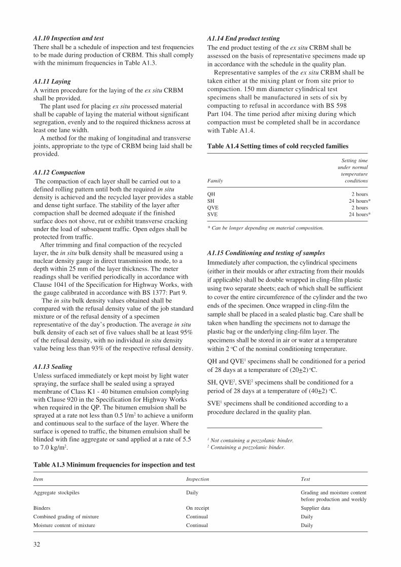
32
A1.10 Inspection and testThere shall be a schedule of inspection and test frequenciesto be made during production of CRBM. This shall complywith the minimum frequencies in Table A1.3.
A1.11 LayingA written procedure for the laying of the ex situ CRBMshall be provided.
The plant used for placing ex situ processed materialshall be capable of laying the material without significantsegregation, evenly and to the required thickness across atleast one lane width.
A method for the making of longitudinal and transversejoints, appropriate to the type of CRBM being laid shall beprovided.
A1.12 Compaction The compaction of each layer shall be carried out to adefined rolling pattern until both the required in situdensity is achieved and the recycled layer provides a stableand dense tight surface. The stability of the layer aftercompaction shall be deemed adequate if the finishedsurface does not shove, rut or exhibit transverse crackingunder the load of subsequent traffic. Open edges shall beprotected from traffic.
After trimming and final compaction of the recycledlayer, the in situ bulk density shall be measured using anuclear density gauge in direct transmission mode, to adepth within 25 mm of the layer thickness. The meterreadings shall be verified periodically in accordance withClause 1041 of the Specification for Highway Works, withthe gauge calibrated in accordance with BS 1377: Part 9.
The in situ bulk density values obtained shall becompared with the refusal density value of the job standardmixture or of the refusal density of a specimenrepresentative of the day’s production. The average in situbulk density of each set of five values shall be at least 95%of the refusal density, with no individual in situ densityvalue being less than 93% of the respective refusal density.
A1.13 SealingUnless surfaced immediately or kept moist by light waterspraying, the surface shall be sealed using a sprayedmembrane of Class K1 - 40 bitumen emulsion complyingwith Clause 920 in the Specification for Highway Workswhen required in the QP. The bitumen emulsion shall besprayed at a rate not less than 0.5 l/m2 to achieve a uniformand continuous seal to the surface of the layer. Where thesurface is opened to traffic, the bitumen emulsion shall beblinded with fine aggregate or sand applied at a rate of 5.5to 7.0 kg/m2.
A1.14 End product testingThe end product testing of the ex situ CRBM shall beassessed on the basis of representative specimens made upin accordance with the schedule in the quality plan.
Representative samples of the ex situ CRBM shall betaken either at the mixing plant or from site prior tocompaction. 150 mm diameter cylindrical testspecimens shall be manufactured in sets of six bycompacting to refusal in accordance with BS 598Part 104. The time period after mixing during whichcompaction must be completed shall be in accordancewith Table A1.4.
Table A1.3 Minimum frequencies for inspection and test
Item Inspection Test
Aggregate stockpiles Daily Grading and moisture contentbefore production and weekly
Binders On receipt Supplier data
Combined grading of mixture Continual Daily
Moisture content of mixture Continual Daily
A1.15 Conditioning and testing of samplesImmediately after compaction, the cylindrical specimens(either in their moulds or after extracting from their mouldsif applicable) shall be double wrapped in cling-film plasticusing two separate sheets; each of which shall be sufficientto cover the entire circumference of the cylinder and the twoends of the specimen. Once wrapped in cling-film thesample shall be placed in a sealed plastic bag. Care shall betaken when handling the specimens not to damage theplastic bag or the underlying cling-film layer. Thespecimens shall be stored in air or water at a temperaturewithin 2 oC of the nominal conditioning temperature.
QH and QVE1 specimens shall be conditioned for a periodof 28 days at a temperature of (20+2) oC.
SH, QVE2, SVE2 specimens shall be conditioned for aperiod of 28 days at a temperature of (40+2) oC.
SVE1 specimens shall be conditioned according to aprocedure declared in the quality plan.
1 Not containing a pozzolanic binder.2 Containing a pozzolanic binder.
Table A1.4 Setting times of cold recycled families
Setting timeunder normal
temperatureFamily conditions
QH 2 hoursSH 24 hours*QVE 2 hoursSVE 24 hours*
* Can be longer depending on material composition.

33
A1.16 End product criteria The minimum specification compliance criteria for theprocess control tests shall be as described in Table A1.5.
In the event of test specimens failing to achieve therequired mechanical performance, compliance shall bedetermined by the testing of cores extracted by dry coringafter one year.
be on ensuring that deleterious materials, such as claylumps and badly weathered aggregate, are excluded fromthe recycled material.
A2.6When determining the grading of materials containingasphalt planings, samples should be dried to constant massat 40 oC and care should be taken not to break down theaggregated particles of asphalt unnecessarily.
A2.7It is good practice to undertake mix design evaluation inadvance of works on site, but it must be recognised thatthis is not always practicable, particularly for smallprojects. Additionally, there will not always be time for thefull design procedure and, in particular, the curing stage tobe carried out in advance of the works. Where this is thecase, information from earlier works with similar materialand the same process or accelerated curing regimes shouldbe taken into consideration.
The components used in the mix design stage shouldrepresent the materials available in the permanent works.Where a representative component is unavailable, thecontractor should use a replacement component of similarproperties in the mix design stage.
The laboratory prepared aggregate should be thoroughlymixed with the measured proportions of the binder andother constituents. The constituents should be the same asthose used in the finished works.
For QVE materials, as well as SVE materials thatcontain pozzolanic binders, the contractor should declarethe indirect tensile stiffness modulus in accordance withBS DD 213 after conditioning.
For SVE materials that do not contain pozzolanicbinders, it is recommended that an accelerated curingregime is used involving curing at 60 oC for 72 hours andthen determining indirect tensile stiffness modulus. Thistest cannot be related to 360 day performance as the valuesobtained in this way may not reflect in situ performance inthe same way as for the other material types.
For QH and SH materials the contractor should declarethe minimum performance class achieved according to thedirect measurement of Dynamic Modulus and FlexuralStrength after conditioning; where these values are notdirectly measurable, suitable alternative apparatus andtransfer functions may be utilised as described below.
Table A1.5 End product criteria
Material Mean fromproperty or Individual test set of sixcharacteristic results measurements
Particle size distribution Zone –Moisture content ±2% –Relative in situ density 93% minimum 95% minimumLayer thickness ±25 mm of specified ±15 mm of specifiedMechanical performance n/a As stated in the QP
Table A2.1 Examples of material families
Quick visco-elastic/ Slow visco-elastic/Quick hydraulic (QH) Slow hydraulic (SH) hydraulic (QVE) hydraulic (SVE)
� Foam/Lime/PFA� Foam/Lime/GGBS� Foam/Lime� Foam/GBS� Foam/’other’� Emulsion/GBS� Emulsion/Lime/PFA� Emulsion/Lime/’other’� Emulsion/’other’
� Foam/PC� Foam/PC/PFA� Foam/PC/GGBS� Foam/PC/’other’� Emulsion/PC� Emulsion/PC/PFA� Emulsion/PC/GGBS� Emulsion/PC/GBS� Emulsion/PC/’other’
� Lime/PFA � Lime/GGBS� Lime/PFA/GGBS� Lime/GBS� Lime/PFA/GBS� Lime/’other’� BOS/GBS
� PC/PFA � PC/GGBS � PC/PFA/GGBS � PC/’other’
A2 Ex situ cold recycled material – notes for guidance
A2.1Examples of the types of materials that satisfy the materialclassifications QH, SH, QVE and SVE are provided inTable A2.1. It is realised that the combinations listed for eachfamily are not exhaustive and alternatives to those shown canbe considered (as indicated by ‘other’ in the table).
A2.2Appendix 7/1 contained in Series 700 of the Notes forGuidance to the Specification for Highways Works(MCHW2) is a widely used method for specifyingpavement constructions, and it is advised that the format ofthis Appendix should be used in the quality plan unlessotherwise requested. The contractor should also justify theconstruction with appropriate references to design chartsor, if requested by the overseeing organisation, by carryingout analytical pavement design.
A2.3The aggregate component should be of a quality generallysuitable for use in cement bound material or asphalt.However, given the nature of the operation, whichinvolves processing arisings from existing road pavements,some discretion should be applied. The emphasis should
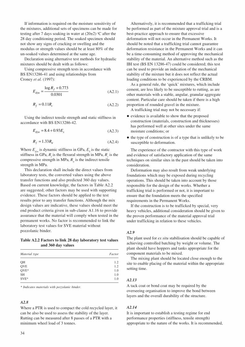
34
If information is required on the moisture sensitivity ofthe mixtures, additional sets of specimens can be made fortesting after 7 days soaking in water at (20±2) oC after the28 day conditioning period. The soaked specimen shouldnot show any signs of cracking or swelling and themodulus or strength values should be at least 80% of theun-soaked values determined at the same age.
Declaration using alternative test methods for hydraulicmixtures should be dealt with as follows:
Using compressive strength tests in accordance withBS EN13286-41 and using relationships fromCroney et al. (1997):
log 0.773
0.0301f
dyn
RE
+= (A2.1)
0.11f cR R= (A2.2)
Using the indirect tensile strength and static stiffness inaccordance with BS EN13286-42.
8.4 0.93dyn sE E= + (A2.3)
1.33f itR R= (A2.4)
Where Edyn
is dynamic stiffness in GPa, ES is the static
stiffness in GPa, Rf is the flexural strength in MPa, R
c is the
compressive strength in MPa, Rit is the indirect tensile
strength in MPa.This declaration shall include the direct values from
laboratory tests, the converted values using the abovetransfer functions and also predicted 360 day values.Based on current knowledge, the factors in Table A2.2are suggested; other factors may be used with supportingevidence. These factors should be applied to the testresults prior to any transfer functions. Although the mixdesign values are indicative, these values should meet theend product criteria given in sub-clause A1.16 to provideassurance that the material will comply when tested in thepermanent works. No factor is recommended to link thelaboratory test values for SVE material withoutpozzolanic binder.
Alternatively, it is recommended that a trafficking trialbe performed as part of the mixture approval trial and is abest-practice approach to ensure that excessivedeformation will not occur in the Permanent Works. Itshould be noted that a trafficking trial cannot guaranteedeformation resistance in the Permanent Works and it canbe a time-consuming method of approving the mechanicalstability of the material. An alternative method such as theIBI test (BS EN 13286-47) could be considered; this testcan be used to provide an indication of the mechanicalstability of the mixture but it does not reflect the actualloading conditions to be experienced by the CRBM.
As a general rule, the ‘quick’ mixtures, which includecement, are less likely to be susceptible to rutting, as areother materials with a stable, angular, granular aggregatecontent. Particular care should be taken if there is a highproportion of rounded gravel in the mixture.
A trafficking trial may not be necessary if:
� evidence is available to show that the proposedconstruction (materials, construction and thicknesses)has performed well at other sites under the samemoisture conditions; or
� the type of construction is of a type that is unlikely to besusceptible to deformation.
The experience of the contractor with this type of workand evidence of satisfactory application of the sametechniques on similar sites in the past should be taken intoconsideration.
Deformation may also result from weak underlyingfoundations which may be exposed during recyclingoperations. This should be taken into account by thoseresponsible for the design of the works. Whether atrafficking trial is performed or not, it is important toensure that the foundation meets the specifiedrequirements in the Permanent Works.
If the construction is to be trafficked by special, veryheavy vehicles, additional consideration should be given tothe proven performance of the material approval trialunder trafficking in relation to these vehicles.
A2.9The plant used for ex situ stabilisation should be capable ofachieving controlled batching by weight or volume. Theplant should have hoppers and tanks appropriate for thecomponent materials to be mixed.
The mixing plant should be located close enough to thesite to enable placing of the material within the appropriatesetting time.
A2.13A tack coat or bond coat may be required by theoverseeing organisation to improve the bond betweenlayers and the overall durability of the structure.
A2.14It is important to establish a testing regime for endperformance properties (stiffness, tensile strength)appropriate to the nature of the works. It is recommended,
Table A2.2 Factors to link 28 day laboratory test valuesand 360 day values
Material type Factor
QH 1.2QVE 1.2QVE* 1.0SH 1.0SVE* 1.0
* Indicates materials with pozzolanic binder.
A2.8Where a PTR is used to compact the cold recycled layer, itcan be also be used to assess the stability of the layer.Rutting can be measured after 8 passes of a PTR with aminimum wheel load of 3 tonnes.
35
given the precision of the testing, that the results areassessed for conformity in sets of six. Thisrecommendation does not, however, mean that a full set ofsix specimens needs to be made up at one time.
For works of a reasonable size, it is recommended thatspecimens are prepared at an overall frequency of three per1000 tonnes with a minimum of three per working day.Conformity should be assessed on a rolling basis.
It may be possible to relax this requirement for smalland intermittent jobs with the prior agreement of theoverseeing organisation.
40kg of material is required for each sample to havesufficient material for the three test samples (PRD,Cylindrical and Moisture Content) to be produced. PRDsamples require a minimum of 5kg of material; Cylindricalsamples, 4kg; Moisture Content samples, 3kg; as well as threepartical size distribution tests from a bulk sample of sixindividual samples.
A2.15Prior to testing, specimens shall be conditioned in acontrolled environment, sealed to keep the moisture in, asdescribed in this clause. The purpose of this conditioningis to simulate the likely curing over the first year in theroad. A PRD or other suitable mould may be used. Wherelong-term storage of materials is required, the use of aninexpensive mould such as a plastic soil pipe is advised.
No curing regime is been specified for SVE materialwithout pozzolanic binders; it is anticipated that alaboratory test of material in early life will not be asuitable method to demonstrate the 360 day performanceof this material. For these materials, early lifedetermination of performance using accelerated curing isrecommended for quality control purposes but not forprediction of 360 day performance.
A2.16The material performance requirements for QVE and SVEtype CRBM are given in terms of indirect tensile stiffnessmodulus as shown in Table A2.3. The materialperformance requirements for QH and SH materials aregiven in terms of flexural strength and dynamic stiffness asshown in Figure A2.1.
Table A2.3 End product requirements for QVE andSVE CRBM at 360 days*
Material class Mean from test set
Class B1 1900 MPaClass B2 2500 MPaClass B3 3100 MPa
* 360 days in situ or cured in accordance with sub clause A1.15.
Figure A2.1 End product requirements of QH and SH CRBM at 360 days*
* 360 days in situ or cured in accordance with sub clause A1.15
The criteria in this sub-clause represent the minimumpermitted end product compliance criteria; however, they canbe supplemented by other laboratory and non-destructive insitu test methods as agreed with the overseeing organisation.For visco-elastic materials, particularly those containingasphalt planings, testing for bitumen content is unlikely to beof value. This aspect of process control is better controlledthrough tank reconciliation. A description of thesupplementary test methods and expected outcomes of thetesting can be included in the quality plan declaration.Supplementary testing can be of value to both the contractorand the overseeing organisation and should be viewed asgood practice. For example, a non-destructive falling weighttest device can, in certain circumstances, be used to show thein situ performance of the layer and also show that curing isoccurring. It is advised that any agreed supplementary testingis used as a tool for ‘acceptance’ (as opposed to ‘rejection’) sothat, along with practical evidence at other sites, these may beused to resolve non-compliance issues should they occur.
0
1
10
1 10 100
Dynamic modulus (GPa)
Fle
xura
l str
engt
h (M
Pa)
Zone
H9
H7
H1H2H3H4H5H6
H8

36
A3 In situ cold recycled bound material – specification
A3.1 GeneralIn situ cold recycled bound material (CRBM) comprisesbase and binder courses produced by the pulverisation andstabilisation of all, or part, of the existing road structure. Insitu CRBM is bound with hydraulic or bituminous binders,separately or in combination. This clause covers fourgeneric material families: quick hydraulic (QH), slowhydraulic (SH), quick visco-elastic (QVE) and slow visco-elastic (SVE). The primary binder of these families ofmaterials shall be as follows:
QH: Portland cement as the main hydraulic componentand excluding bituminous binders.
SH: Hydraulic binders (e.g. PFA/lime and GBS/lime)excluding bituminous binders and portland cement.
QVE: Bituminous binder as the main component but alsoincluding portland cement.
SVE: Bituminous binder as main component butexcluding portland cement.
In situ CRBM shall be designed to achieve the specifiedlevel of the appropriate end performance property
A3.2 Quality planIn situ CRBM shall be produced to a quality plan (QP)with the following elements:
� Sourcing of additional aggregate and other constituents.
� Declaration of constituents and the job standard mixture.
� Process control of pulverisation and mixing.
� Inspection and test schedules.
� Demonstration of performance properties.
A3.3 Sourcing of aggregateThe quality plan shall contain details of all aggregates,including the pulverised road, to be used in the CRBM.Aggregate may include:
� Asphalt, concrete or granular material pulverised,planed or excavated from a road or other paved area.
� Fillers from primary or secondary sources (e.g. PFA).
The pulverised aggregate, including added filler, shallnot contain deleterious material that adversely affects theperformance of the mixture.
A3.4. Processing of aggregateNot used
A3.5 Binders and other constituents
� Bitumen emulsion shall conform with BS 434-1 and beused in accordance with BS 434-2.
� Cement shall conform to EN 197-1.
� Bitumen used for foaming shall conform with EN12591and shall be grade 160/220 or harder.
� Granulated blast furnace slag (GBS) shall comply withEN 14227-2.
� Ground granulated blast furnace slag (GGBS) shallcomply with EN 14227-2.
� Lime shall comply with EN 14227-11.
� Fly ash (PFA) used as either as filler or pozzolan, shallcomply with EN 14227-4.
� Un-weathered 0/4 mm basic oxygen slag (BOS) slagfines used in SH material as activator/accelerator to theGBS shall comply with BS 6463 Part 102
� Other constituents, including setting and hardeningagents, may be used to enhance the performance of themixture, subject to the approval of the overseeingorganisation.
� Water shall not contain material that adversely affectsthe performance of the mixture.
A3.6 Job standard mixtureThe composition of the job standard mixture shall bedeclared as follows:
� Source, origin and proportion of all aggregateconstituents.
� Combined target grading, including mineral binders andtolerances.
� Source, origin and proportion of all binders.
� Target moisture content.
The grading of the job standard mixture (the aggregatetogether with the other constituents including hydraulicbinders) shall comply with one of the zones in Table A3.1.
Table A3.1 Particle size distribution of mixture for coldrecycling
Percentage by mass passing
Sieve (mm) Zone A Zone B Zone C
40 100 100 10031,5 100 100 86-10020 100 100 75-10014 85-100 85-100 52-10010 68-100 68-100 44-1004 38-74 38-94 26-742 26-58 26-84 18-580,5 13-38 13-64 8-380,250 9-28 9-51 5-280,063 5-21 5-38 3-21
Use of Zone B or C graded material shall be permittedonly when the results of a full mix design showingcompliance with the required 28 day performance propertiesare available or when evidence can be provided ofsatisfactory achievement of the performance requirementson an earlier contract with a similar composition.
The addition of binder shall comply with Table A3.2.
A3.7 Mixture design validationWhen a mixture design validation is required it shall becarried out on aggregates and binders representative ofthose to be used in the works. The validation may becarried out on CRBM mixed in the laboratory.

37
The target mixture shall comply with sub-clause A3.5.A preliminary exercise shall be undertaken to establish a
target grading and suitable moisture content.Representative samples of the mixture shall be taken,
from which 150 mm diameter cylindrical specimens shall beproduced in accordance with sub clause A3.14. The heightof these specimens shall be appropriate to the mechanicalperformance test declared in the quality plan. The timebetween mixing and specimen production shall be kept to aminimum but within the setting times given in Table A3.4.
The density of each specimen shall be measured and,using the respective moisture content values, the drydensity values shall be determined.
The cylindrical specimens shall be conditioned andtested in accordance with sub clauses A3.15 and A3.16.
The performance properties of the conditionedspecimens shall be declared. The results shall beconsidered as indicative only; the end product compliancecriteria, as stated in sub-clause A3.16, shall apply only tothe specimens prepared during the execution of the works.
A3.8 Trafficking trialA trafficking trial shall be undertaken when required in theQP to demonstrate that the CRBM is not prone toexcessive rutting in its early life.
A trial area shall be laid using the materials and plant tobe used for the main works and on a foundation typical ofthat in the main works. The trial area shall be left to curefor 24 hours, or other declared time, and shall then besubjected to controlled trafficking. The trafficking shall beperformed by a heavy goods vehicle with an axleconfiguration and loading typical of that to be encounteredin the construction phase. The number of passes shallequate to the total expected amount of traffic to be carriedduring construction, with a default value equivalent to100 standard axles.
The measured rutting in the trafficking trial shall be lessthan 10 mm or that stated in the job specific appendix.
A3.9 Process controlProduction of the in situ CRBM shall be subject to processcontrol detailed in the quality plan and meeting thefollowing requirements:
� There shall be a description of the plant and theproduction process, preferably including a flow diagram,detailing how material is to be produced in accordancewith this specification. A description of the systematicpattern of the pulverisation and stabilisation process shallbe included.
� Measures to deal with hard edges and obstructions shallbe included.
� Calibration schedules for all parts of the plant involvedin determining mix consistency shall be provided.Calibration records shall accompany these schedules.
� Measures to avoid problems caused by extreme weather.In particular, construction shall not proceed if road and/or other materials are frozen or excessively wet.
A3.10 Inspection and testThere shall be a schedule of inspection and test frequenciesto be made during production of CRBM. This shall complywith the minimum frequencies in Table A3.3.
Table A3.3 Minimum frequencies for inspection and test
Item Inspection Test
Aggregate stockpiles* Daily Grading and moisture contentbefore production and weekly
Binders On receipt Supplier dataCombined grading of mixture Continual DailyMoisture content of mixture Continual Daily
* If applicable.
A3.11 LayingA written procedure for the levelling of the in situ CRBMshall be provided.
The plant used for levelling the in situ processedmaterial shall be capable of levelling without significantsegregation, evenly and to the required thickness acrossthe full width.
A method for the forming of longitudinal and transversejoints shall be provided that is appropriate to the type ofCRBM being laid.
Table A3.2 Minimum binder contents for in situ construction by family and binder type
Family OPC Lime BOS PFA GBS GGBS Bitumen1
QH 4% – – – – – –3% – – 5% – – –3% – – – 5% – –3% – – – – 3% –
SH – 3% – 10% – – –– 3% – – 10% – –– 3% – – – 6% –– 2% – – 10% – –– – 2.5% – 10% – –
QVE 1% – – 2 – – 4%
SVE – 2.5%3 – 2 – – 4%
1 foamed or emulsion (residual).2 PFA may be added as filler. 3 lime may be added for ‘breaking’ and adhesion purposes, and, if PFA included as filler, will contribute to strength.
38
A3.12 CompactionThe compaction of each layer shall be carried out to adefined rolling pattern until both the required in situdensity is achieved and the recycled layer provides a stableand dense tight surface. The stability of the layer aftercompaction shall be deemed adequate if the finishedsurface does not shove, rut or exhibit transverse crackingunder the load of subsequent traffic. Open edges shall beprotected from traffic.
After trimming and final compaction of the recycledlayer, the in situ bulk density shall be measured using anuclear density gauge in direct transmission mode, to adepth within 25 mm of the layer thickness. The meterreadings shall be verified periodically in accordance withClause 1041 of the Specification for Highway Works, withthe gauge calibrated in accordance with BS 1377: Part 9.
The in situ bulk density values obtained shall becompared with the refusal density value of the job standardmixture or of the refusal density of a specimenrepresentative of the day’s production. The average in situbulk density of each set of five values shall be at least 95%of the refusal density, with no individual in situ densityvalue being less than 93% of the respective refusal density.
A3.13 SealingUnless surfaced immediately or kept moist by light waterspraying, the surface shall be sealed using a sprayedmembrane of Class K1 - 40 bitumen emulsion complyingwith Clause 920 in the Specification for Highway Workswhen required in the quality plan. The bitumen emulsionshall be sprayed at a rate not less than 0.5 l/m2 to achieve auniform and continuous seal to the surface of the layer.Where the surface is opened to traffic, the bitumenemulsion shall be blinded with fine aggregate or sandapplied at a rate of 5.5 to 7.0 kg/m2.
A3.14 End product testingThe end product testing of the in situ CRBM shall beassessed on the basis of representative specimens made upin accordance with the schedule in the quality plan.
Representative samples of the in situ CRBM shall betaken at the stabilisation plant prior to compaction. 150 mmdiameter cylindrical test specimens shall be manufactured insets of six by compacting to refusal in accordance withBS 598: Part 104. The time period after mixing duringwhich compaction must be completed shall be in accordancewith Table A3.4.
A3.15 Conditioning and testing of samplesImmediately after compaction, the cylindrical specimens(either in their moulds or after extraction from the mouldsif applicable), shall be double wrapped in cling-film plasticusing two separate sheets, each of which shall be sufficientto cover the entire circumference of the cylinder and thetwo ends of the specimen. Once wrapped in cling-film, thesample shall be placed in a sealed plastic bag. Care shall betaken when handling the specimens not to damage theplastic bag or the underlying cling-film layer. Thespecimens shall be stored in air or water at a temperaturewithin 2 oC of the nominal conditioning temperature.
QH and QVE1 specimens shall be conditioned for a periodof 28 days at a temperature of (20+2) oC.
SH, QVE2, SVE2 specimens shall be conditioned for aperiod of 28 days at a temperature of (40+2) oC.
SVE1 specimens shall be conditioned according to aprocedure declared in the quality plan.
A3.16. End product criteria The minimum specification compliance criteria for theprocess control tests shall be as described in Table A3.5.
Table A3.5 End product criteria
Material Mean fromproperty or Individual test set of sixcharacteristic results measurements
Particle size distribution Zone –Moisture content ±2% –Relative in situ density 93% minimum 95% minimumLayer thickness ±25 mm of specified ±15 mm of specifiedMechanical performance n/a As stated in the QP
In the event of test specimens failing to achieve therequired mechanical performance, compliance shall bedetermined by the testing of cores extracted by dry coringafter one year. The results shall be compared with thematerial performance requirements in the QP.
A4 In situ cold recycled material – Notes for guidance
A4. 1 GeneralExamples of the types of materials that satisfy the materialclassifications QH, SH, QVE and SVE are provided below. Itis realised that the combinations listed in Table A4.1 for eachfamily are not exhaustive and alternatives to those shown canbe considered (as indicated by ‘other’ in the table).
A4.2 Quality planAppendix 7/1 contained in Series 700 of the Notes forGuidance to the Specification for Highways Works(MCHW2) is a widely used method for specifyingpavement construction, and it is advised that the format ofthis Appendix should be used in the quality plan unlessotherwise requested. The contractor should also justify the
1 Not containing a pozzolanic binder.2 Containing a pozzolanic binder.
Table A3.4 Setting times of cold recycled families
Setting timeunder normal
temperatureFamily conditions
QH 2 hoursSH 24 hours*QVE 2 hoursSVE 24 hours*
* Can be longer depending on material composition.
39
construction with appropriate references to design chartsor, if requested, by the overseeing organisation, carryingout analytical pavement design.
A4.3 Sourcing of aggregateThe aggregate component should be of a quality generallysuitable for use in cement bound material or asphalt.However, given the nature of the operation, whichinvolves processing arisings from existing road pavements,some discretion should be applied. The emphasis shouldbe on ensuring that deleterious materials, such as claylumps and badly weathered aggregate are excluded fromthe recycled material.
A4.6 Job standard mixtureWhen determining the grading of materials containingasphalt planings, samples should be dried to constant massat 40 oC and care should be taken not to break down theaggregated particles of asphalt unnecessarily.
A4.7 Mixture design validation It is good practice to undertake mix design evaluation inadvance of works on site, but it must be recognised thatthis is not always practicable, particularly for smallprojects. Additionally, there will not always be time for thefull design procedure and, in particular, the curing stage tobe carried out in advance of the works. Where this is thecase, information from earlier works with the same processor accelerated curing regimes should be taken intoconsideration.
The components used in the mix design stage shouldrepresent the materials available in the permanent works.Where a representative component is unavailable, thecontractor should use a replacement component of similarproperties in the mix design stage.
The laboratory prepared aggregate should be thoroughlymixed with the measured proportions of the binder andother constituents. The constituents shall be the same asthose used in the finished works.
For QVE materials, as well as SVE materials thatcontain pozzolanic binders, the contractor should declarethe indirect tensile stiffness modulus in accordance withBS DD 213 after conditioning.
For SVE materials that do not contain pozzolanicbinders, it is recommended that an accelerated curing
regime is used involving curing at 60 oC for 72 hours andthen determining indirect tensile stiffness modulus. Thistest cannot be related to 360 day performance as the valuesobtained in this way may not reflect in situ performance inthe same way as for the other material types.
For QH and SH materials the contractor should declarethe minimum performance class achieved according to thedirect measurement of dynamic modulus and flexuralstrength after conditioning; where these values are notdirectly measurable, suitable alternative apparatus andtransfer functions may be utilised as described below.
If information is required on the moisture sensitivity ofthe mixtures, additional sets of specimens can be made fortesting after 7 days soaking in water at (20±2) oC after the28 day conditioning period. The soaked specimens shouldnot show any signs of cracking or swelling and themodulus or strength values should be at least 80% of theun-soaked values determined at the same age.
Declaration using alternative test methods for hydraulicmixtures should be dealt with as follows:
Using compressive strength tests in accordance withBS EN13286-41 and using relationships from Croney et al.(1997):
log 0.773
0.0301f
dyn
RE
+= (4.1)
0.11f cR R= (4.2)
Using the indirect tensile strength and static stiffness inaccordance with BS EN13286-42:
8.4 0.93dyn sE E= + (4.3)
1.33f itR R= (4.4)
Where Edyn
is dynamic stiffness in GPa, ES is the static
stiffness in GPa, Rf is the flexural strength in MPa, R
c is the
compressive strength in MPa, Rit is the indirect tensile
strength in MPa.This declaration shall include the direct values from
laboratory tests, the converted values using the abovetransfer functions and also predicted 360 day values.Based on current knowledge, the factors in Table A4.2are suggested; other factors may be used with supportingevidence. These factors should be applied to the testresults prior to any transfer functions. Although the mix
Table A4.1 Examples of material families
Quick visco-elastic/ Slow visco-elastic/Quick hydraulic (QH) Slow hydraulic (SH) hydraulic (QVE) hydraulic (SVE)
� Foam/Lime/PFA� Foam/Lime/GGBS� Foam/Lime� Foam/GBS� Foam/’other’� Emulsion/GBS� Emulsion/Lime/PFA� Emulsion/Lime/’other’� Emulsion/’other’
� Foam/PC� Foam/PC/PFA� Foam/PC/GGBS� Foam/PC/’other’� Emulsion/PC� Emulsion/PC/PFA� Emulsion/PC/GGBS� Emulsion/PC/GBS� Emulsion/PC/’other’
� Lime/PFA � Lime/GGBS� Lime/PFA/GGBS� Lime/GBS� Lime/PFA/GBS� Lime/’other’� BOS/GBS
� PC/PFA � PC/GGBS � PC/PFA/GGBS � PC/’other’
40
design values are indicative, these values should meet theend product criteria given in sub-clause A3.16 to provideassurance that the material will comply when tested in thepermanent works. No factor is recommended to link thelaboratory test values for SVE material withoutpozzolanic binder.
A4.8 Trafficking trialWhere a PTR is used to compact the cold recycled layer, itcan be also be used to assess the stability of the layer.Rutting can be measured after 8 passes of a PTR with aminimum wheel load of 3 tonnes.
Alternatively, it is recommended that a trafficking trialbe performed as part of the mixture approval trial and is abest-practice approach to ensure that excessivedeformation will not occur in the permanent works. Itshould be noted that a trafficking trial cannot guaranteedeformation resistance in the Permanent Works and it canbe a time-consuming method of approving the mechanicalstability of the material. An alternative method such as theIBI test (BS EN 13286-47) could be considered; this testcan be used to provide an indication of the mechanicalstability of the mixture but it does not reflect the actualloading conditions to be experienced by the CRBM.
As a general rule, the ‘quick’ mixtures, which includecement, are less likely to be susceptible to rutting, as areother materials with a stable, angular, granular aggregatecontent. Particular care should be taken if there is a highproportion of rounded gravel.
A trafficking trial may not be necessary if:
� evidence is available to show that the proposedconstruction (materials, construction and thicknesses)has performed well at other sites under the samemoisture conditions; or
� the type of construction is of a type that is unlikely to besusceptible to deformation.
The experience of the contractor with this type of workand evidence of satisfactory application of the sametechniques on similar sites in the past should be taken intoconsideration.
Deformation may also result from weak underlyingfoundations which may be exposed during recyclingoperations. This should be taken into account by thoseresponsible for the design of the works. Whether atrafficking trial is performed or not, it is important toensure that the foundation meets the specifiedrequirements in the Permanent Works.
If the construction is to be trafficked by special, veryheavy vehicles, additional consideration should be given tothe proven performance of the material approval trialunder trafficking in relation to these vehicles.
A4.9 Process controlPulverisation of the existing road structure should becarried out in a systematic pattern, to the required depth, toensure that it covers all parts of the existing road; adescription of the pattern should be given in the QP. Anoverlap of at least 150 mm should be made betweenadjacent passes of the machine. Any material missed alonghard edges or around obstructions should be excavated andplaced in the path of subsequent passes of the machineuntil a uniform fully pulverised aggregate is obtained. Thesurface of the pulverised layer should be graded to therequired level profile and nominally compacted.
Where work continues adjacent to previously recycledmaterial, transverse joints should be reformed a minimum0.5 m into the previously treated construction. Where alayer of material for recycling is placed over a layerpreviously recycled, the depth of pulverisation/stabilisationof the upper layer should be set to cut into the underlyingrecycled layer by at least 20 mm.
Excess pulverised material should be removed by graderand/or excavator for use elsewhere on site or transported tostockpile at locations given in the QP. The surface of thelayer should be graded to the required level profile andnominally compacted.
The moisture content of the pulverised aggregateimmediately prior to stabilisation should be measured inaccordance with BS 812: Part 109 using a method suitablefor subsequent process control testing. The moisturecontent should be uniform throughout the layer within therange ±2% of optimum moisture content for the pulverisedaggregate including any designed proportion of filler,determined in accordance with BS 1924: Part 2 (1990).
If the moisture content of the pulverised aggregate failsto meet the specified moisture content range, correctiveaction should be taken either by aeration to reduce themoisture content or controlled addition of water to increasethe moisture content.
Prior to stabilisation, pulverised materials within 100 mmof restricted hard edges such as kerbs and channels, oraround obstructions such as gullies, should be removedand spread uniformly over the remaining full width of thepulverised material.
The stabilisation should be carried out to the requireddepth in a systematic pattern similar to that used for thepulverisation process, with an overlap of at least 150 mmbetween adjacent passes of the machine using a methodapproved by the overseeing organisation.
The layer of recycled material should be graded to leveland compacted within two hours of the final pass of thestabilising plant, unless a curing or ‘maturing’ period ofaeration is required. Any furrow formed by priorexcavation of edge material should be re-filled by gradingthe adjacent recycled material into the space using aminimum amount of re-working.
Table A4.2 Factors to link laboratory test values and360 day values
Material type Factor
QH 1.2QVE 1.2QVE* 1.0SH 1.0SVE* 1.0
* Indicates materials with pozzolanic binder.
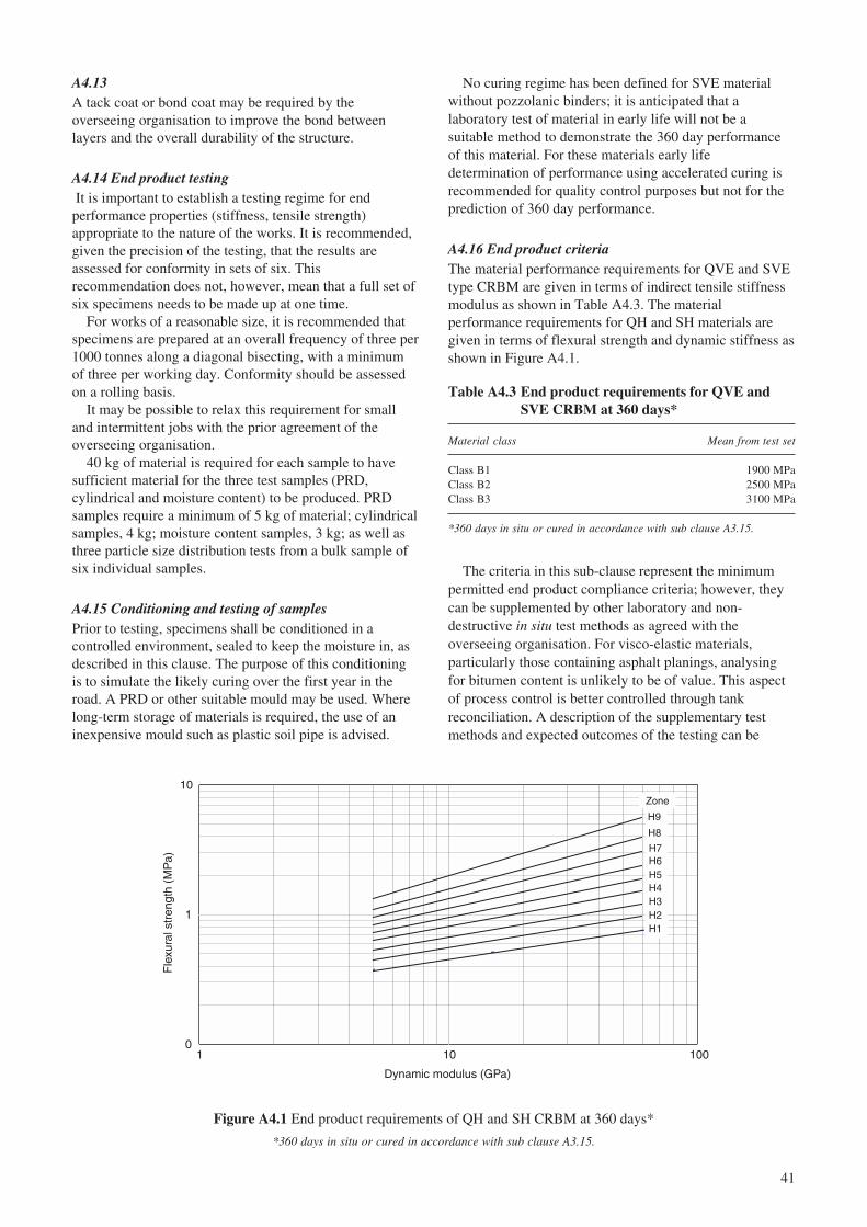
41
A4.13A tack coat or bond coat may be required by theoverseeing organisation to improve the bond betweenlayers and the overall durability of the structure.
A4.14 End product testing It is important to establish a testing regime for endperformance properties (stiffness, tensile strength)appropriate to the nature of the works. It is recommended,given the precision of the testing, that the results areassessed for conformity in sets of six. Thisrecommendation does not, however, mean that a full set ofsix specimens needs to be made up at one time.
For works of a reasonable size, it is recommended thatspecimens are prepared at an overall frequency of three per1000 tonnes along a diagonal bisecting, with a minimumof three per working day. Conformity should be assessedon a rolling basis.
It may be possible to relax this requirement for smalland intermittent jobs with the prior agreement of theoverseeing organisation.
40 kg of material is required for each sample to havesufficient material for the three test samples (PRD,cylindrical and moisture content) to be produced. PRDsamples require a minimum of 5 kg of material; cylindricalsamples, 4 kg; moisture content samples, 3 kg; as well asthree particle size distribution tests from a bulk sample ofsix individual samples.
A4.15 Conditioning and testing of samplesPrior to testing, specimens shall be conditioned in acontrolled environment, sealed to keep the moisture in, asdescribed in this clause. The purpose of this conditioningis to simulate the likely curing over the first year in theroad. A PRD or other suitable mould may be used. Wherelong-term storage of materials is required, the use of aninexpensive mould such as plastic soil pipe is advised.
No curing regime has been defined for SVE materialwithout pozzolanic binders; it is anticipated that alaboratory test of material in early life will not be asuitable method to demonstrate the 360 day performanceof this material. For these materials early lifedetermination of performance using accelerated curing isrecommended for quality control purposes but not for theprediction of 360 day performance.
A4.16 End product criteriaThe material performance requirements for QVE and SVEtype CRBM are given in terms of indirect tensile stiffnessmodulus as shown in Table A4.3. The materialperformance requirements for QH and SH materials aregiven in terms of flexural strength and dynamic stiffness asshown in Figure A4.1.
Figure A4.1 End product requirements of QH and SH CRBM at 360 days*
*360 days in situ or cured in accordance with sub clause A3.15.
Table A4.3 End product requirements for QVE andSVE CRBM at 360 days*
Material class Mean from test set
Class B1 1900 MPaClass B2 2500 MPaClass B3 3100 MPa
*360 days in situ or cured in accordance with sub clause A3.15.
The criteria in this sub-clause represent the minimumpermitted end product compliance criteria; however, theycan be supplemented by other laboratory and non-destructive in situ test methods as agreed with theoverseeing organisation. For visco-elastic materials,particularly those containing asphalt planings, analysingfor bitumen content is unlikely to be of value. This aspectof process control is better controlled through tankreconciliation. A description of the supplementary testmethods and expected outcomes of the testing can be
0
1
10
1 10 100
Dynamic modulus (GPa)
Fle
xura
l str
engt
h (M
Pa)
Zone
H9
H7
H1H2H3H4H5H6
H8
42
included in the quality plan declaration. Supplementarytesting can be of value to both the contractor and theoverseeing organisation and should be viewed as goodpractice. For example, a non-destructive falling weight testdevice can in certain circumstances be used to show the insitu performance of the layer and also show that curing isoccurring. It is advised that any agreed supplementarytesting is used as a tool for ‘acceptance’ (as opposed to‘rejection’) so that, along with practical evidence at othersites, these may be used to resolve non-compliance issuesshould they occur.
A5 References
British Standards Institution (1984). Bitumen roademulsions (anionic and cationic). Specification for bitumenroad emulsions. BS 434-1. London: British StandardsInstitution.
British Standards Institution (1984). Bitumen roademulsions (anionic and cationic). Code of practice for useof bitumen road emulsions. BS 434-2. London: BritishStandards Institution.
British Standards Institution (1989). Sampling andexamination of bituminous mixtures for roads and otherpaved areas. Methods of test for determination of densityand compaction. BS598 Part 104. London: BritishStandards Institution.
British Standards Institution (1990). Method of test forsoils for civil engineering purposes. In situ tests. BS1377Part 9. London: British Standards Institution.
British Standards Institution (1993). Method fordetermination of indirect tensile stiffness modulus ofbituminous mixtures. DD 213. London: British StandardsInstitution.
British Standards Institution (2000). Cement,composition, specifications and conformity criteria forcommon cements. BS EN 197-1. London: BritishStandards Institution.
British Standards Institution (2000). Testing concrete instructures. Cored specimens. Taking, examining andtesting in compression. BS EN12504. London: BritishStandards Institution.
British Standards Institution (2000). Bitumen andbituminous binders. Specifications for paving gradebitumen. BS EN12591. London: British StandardsInstitution.
British Standards Institution (2001). Quicklime,hydrated lime and natural calcium carbonate. Methods forchemical analysis. BS 6463 Part 102. London: BritishStandards Institution.
British Standards Institution (2001). Unbound andhydraulically bound mixtures. Specifications. Part 2: Slagbound mixtures. Definitions, composition, classification.BS EN 14227-2. London: British Standards Institution.
British Standards Institution (2001). Unbound andhydraulically bound mixtures. Specifications. Part 3: Flyash for bound mixtures. Definitions, composition,classification. BS EN 14227-3. London: British StandardsInstitution.
British Standards Institution (2001). Unbound andhydraulically bound mixtures. Specifications. Part 11: Soiltreated by lime. BS EN 14227-11. London: BritishStandards Institution.
British Standards Institution (2003). Unbound andhydraulically bound mixtures. Test method for thedetermination of compressive strength of hydraulicallybound mixtures. BS EN 13286-41. London: BritishStandards Institution.
British Standards Institution (2003). Unbound andhydraulically bound mixtures. Test method for thedetermination of the indirect tensile strength ofhydraulically bound mixtures. BS EN 13286-42. London:British Standards Institution.
British Standards Institution (2003c). Unbound andhydraulically bound mixtures. Test method for thedetermination of California bearing ratio, immediatebearing index and linear swelling. BS EN 13286-47.London: British Standards Institution.
Croney D and P Croney (1997). Design and performanceof road pavements. 3rd Edition. ISBN 0-07-707408-4.Maidenhead: McGraw Hill.
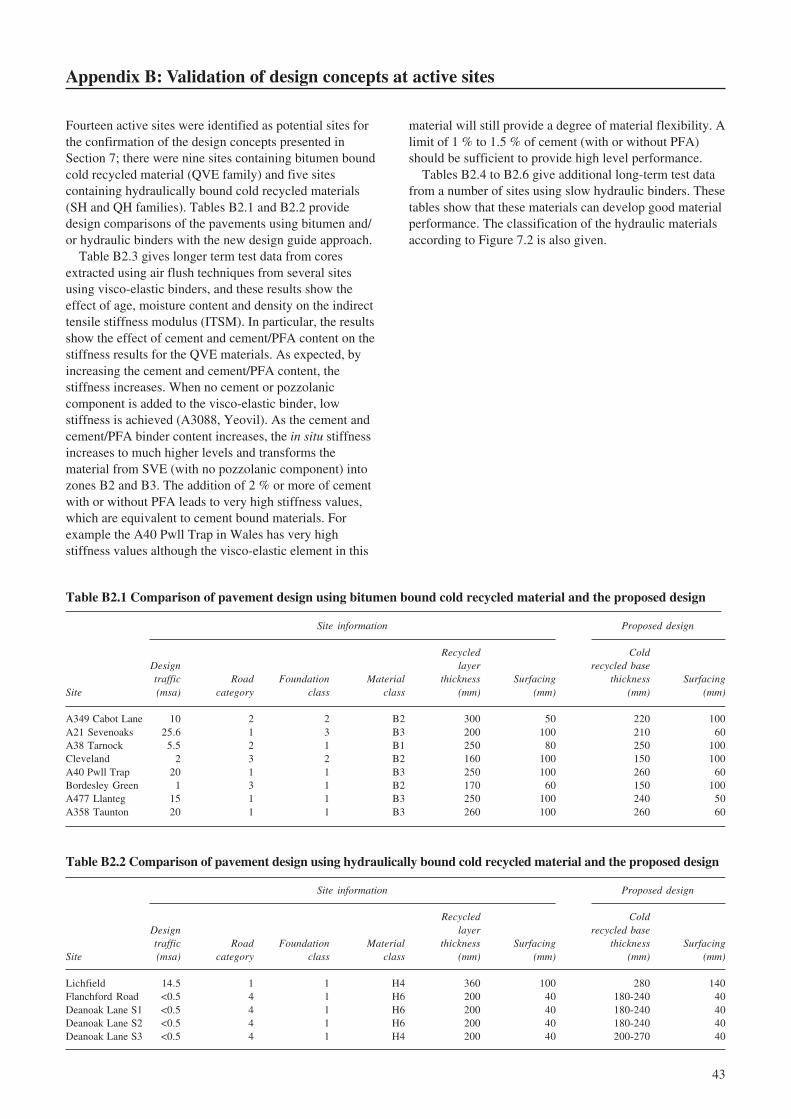
43
Appendix B: Validation of design concepts at active sites
Fourteen active sites were identified as potential sites forthe confirmation of the design concepts presented inSection 7; there were nine sites containing bitumen boundcold recycled material (QVE family) and five sitescontaining hydraulically bound cold recycled materials(SH and QH families). Tables B2.1 and B2.2 providedesign comparisons of the pavements using bitumen and/or hydraulic binders with the new design guide approach.
Table B2.3 gives longer term test data from coresextracted using air flush techniques from several sitesusing visco-elastic binders, and these results show theeffect of age, moisture content and density on the indirecttensile stiffness modulus (ITSM). In particular, the resultsshow the effect of cement and cement/PFA content on thestiffness results for the QVE materials. As expected, byincreasing the cement and cement/PFA content, thestiffness increases. When no cement or pozzolaniccomponent is added to the visco-elastic binder, lowstiffness is achieved (A3088, Yeovil). As the cement andcement/PFA binder content increases, the in situ stiffnessincreases to much higher levels and transforms thematerial from SVE (with no pozzolanic component) intozones B2 and B3. The addition of 2 % or more of cementwith or without PFA leads to very high stiffness values,which are equivalent to cement bound materials. Forexample the A40 Pwll Trap in Wales has very highstiffness values although the visco-elastic element in this
Table B2.2 Comparison of pavement design using hydraulically bound cold recycled material and the proposed design
Site information Proposed design
Recycled ColdDesign layer recycled basetraffic Road Foundation Material thickness Surfacing thickness Surfacing
Site (msa) category class class (mm) (mm) (mm) (mm)
Lichfield 14.5 1 1 H4 360 100 280 140Flanchford Road <0.5 4 1 H6 200 40 180-240 40Deanoak Lane S1 <0.5 4 1 H6 200 40 180-240 40Deanoak Lane S2 <0.5 4 1 H6 200 40 180-240 40Deanoak Lane S3 <0.5 4 1 H4 200 40 200-270 40
Table B2.1 Comparison of pavement design using bitumen bound cold recycled material and the proposed design
Site information Proposed design
Recycled ColdDesign layer recycled basetraffic Road Foundation Material thickness Surfacing thickness Surfacing
Site (msa) category class class (mm) (mm) (mm) (mm)
A349 Cabot Lane 10 2 2 B2 300 50 220 100A21 Sevenoaks 25.6 1 3 B3 200 100 210 60A38 Tarnock 5.5 2 1 B1 250 80 250 100Cleveland 2 3 2 B2 160 100 150 100A40 Pwll Trap 20 1 1 B3 250 100 260 60Bordesley Green 1 3 1 B2 170 60 150 100A477 Llanteg 15 1 1 B3 250 100 240 50A358 Taunton 20 1 1 B3 260 100 260 60
material will still provide a degree of material flexibility. Alimit of 1 % to 1.5 % of cement (with or without PFA)should be sufficient to provide high level performance.
Tables B2.4 to B2.6 give additional long-term test datafrom a number of sites using slow hydraulic binders. Thesetables show that these materials can develop good materialperformance. The classification of the hydraulic materialsaccording to Figure 7.2 is also given.

44
Tab
le B
2.3
Sum
mar
y of
tes
t re
sult
s ob
tain
ed o
n in
situ
Foa
mix
cor
es e
xtra
cted
fro
m s
elec
ted
site
s
Con
diti
onA
s re
ceiv
edD
ry a
t 20
o C
Lay
erU
pper
Low
erU
pper
Low
er
Bul
kB
ulk
Bul
kB
ulk
Stif
fnes
sM
Cde
nsit
ySt
iffn
ess
MC
dens
ity
Stif
fnes
sM
Cde
nsit
ySt
iffn
ess
MC
dens
ity
Age
to
date
(MP
a)(%
)M
g/m
3(M
Pa)
(%)
Mg/
m3
(MP
a)(%
) M
g/m
3(M
Pa)
(%)
Mg/
m3
Mix
ture
det
ails
Inci
nera
tor
plan
t H
aver
ton
Hill
, B
illin
gham
, C
leve
land
4 ye
ars
and
3475
9.4
2.17
824
969.
42.
0946
813.
62.
669
1951
32.
713
100%
cru
shed
con
cret
e ag
greg
ates
(28
/0)
3 m
onth
s39
588.
42.
2118
099.
62.
073
5945
3.2
2.97
924
982.
62.
805
1% c
emen
t41
248.
52.
164
1158
8.8
1.76
949
673.
62.
766
1100
2.2
2.44
92.
8% F
B (
150
pen)
1347
7.7
2.09
632
569.
22.
1617
943
2.61
3688
32.
748
1% w
ater
3226
21
80
4347
23
09
A40
Pw
ll T
rap,
St
Cle
ars,
Wal
es1
year
and
1183
211
.61.
9892
494.
12.
159
1228
611
.91.
975
8828
4.4
2.15
495
% w
et m
ix m
acad
am (
28/0
)9
mon
ths
7179
6.9
2.25
114
008
4.7
2.24
274
957.
12.
245
1205
35
2.23
65%
PFA
9509
7.8
2.29
1338
17.
32.
319
9465
8.1
2.28
313
600
7.5
2.31
32.
0% c
emen
t14
072
52.
304
1451
84.
62.
349
1396
34.
82.
298
1393
24.
32.
342
3% F
B (
150
pen)
1186
74.
62.
312
8158
12.2
2.24
410
670
4.1
2.30
182
2311
.92.
237
0.5%
-1.5
% w
ater
1386
74.
72.
344
1413
56.
22.
3414
779
4.4
2.33
613
563
5.9
2.33
410
767
4.7
2.32
611
030
4.4
2.22
110
559
4.5
2.32
111
332
4.2
2.21
615
324
8.5
2.24
311
461
4.4
2.27
116
622
8.5
2.24
410
525
4.1
2.26
417
984
6.9
2.29
1618
83.
82.
291
1770
96.
72.
286
1602
13.
52.
286
1248
912
459
1261
612
008
Bor
desl
ey G
reen
, B
irm
ingh
am4
year
sC
rack
ed9.
42.
014
2403
111.
966
Cra
cked
2.8
1.90
933
053.
11.
853
60%
rec
ycle
d ag
greg
ates
pre
dom
inan
tly25
0411
2.03
237
5911
2.02
241
163.
11.
905
5766
2.9
1.90
9cr
ushe
d co
ncre
te29
0211
2.00
933
2411
2.03
545
653
1.9
4986
2.9
1.92
940
% R
AP
3331
111.
992
3270
112.
018
4403
2.8
1.88
746
932.
81.
906
1.5%
cem
ent
3469
121.
997
3981
112.
029
4282
3.1
1.87
248
442.
81.
926
2.8%
FB
(15
0pen
)13
1512
1.97
333
5312
2.02
213
562.
91.
846
4286
31.
904
1% w
ater
3527
132.
053
1911
112.
022
4389
2.9
1.86
527
172.
71.
901
1469
112.
043
1975
112.
012
2580
2.7
1.92
130
643.
11.
887
2450
121.
996
2047
112.
032
3911
2.8
1.88
135
352.
21.
912
2621
2891
3700
4133

45
Tab
le B
2.3
(Con
tinu
ed)
Sum
mar
y of
test
res
ults
obt
aine
d on
in s
itu F
oam
ix c
ores
ext
ract
ed fr
om s
elec
ted
site
s
Con
diti
onA
s re
ceiv
edD
ry a
t 20
o C
Lay
erU
pper
Low
erU
pper
Low
er
Bul
kB
ulk
Bul
kB
ulk
Stif
fnes
sM
Cde
nsit
ySt
iffn
ess
MC
dens
ity
Stif
fnes
sM
Cde
nsit
ySt
iffn
ess
MC
dens
ity
Age
to
date
(MP
a)(%
)M
g/m
3(M
Pa)
(%)
Mg/
m3
(MP
a)(%
) M
g/m
3(M
Pa)
(%)
Mg/
m3
Mix
ture
det
ails
A47
7,
Lla
nteg
6
mon
ths
4436
5.6
2.26
7763
4.8
2.33
161
653.
22.
236
8306
3.3
2.31
695
% R
AP
4526
5.5
2.25
463
805.
12.
2458
013.
22.
231
7710
3.2
2.22
5% P
FA45
425.
22.
347
8567
4.5
2.27
749
873
2.32
490
603
2.26
21.
5% c
emen
t23
235.
52.
243
8569
5.3
2.25
732
672.
82.
214
7891
3.6
2.24
3% F
B (
150
pen)
3445
52.
255
8252
4.7
2.28
737
692.
62.
229
7983
3.2
2.27
30.
5%-1
.5%
wat
er37
845.
32.
236
6611
4.9
2.29
345
762.
72.
207
7102
3.2
2.27
6
6022
5.9
2.19
776
245.
22.
348
7081
3.5
2.17
479
563.
12.
327
55
235.
82.
2849
815.
22.
266
7106
3.3
2.25
567
742.
92.
24
4325
7343
5344
7848
A35
8 H
atch
Bea
ucha
mp
Tau
nton
, Som
erse
t12
mon
ths
3128
5.2
2.05
455
055.
22.
171
3281
3.5
2.02
159
143.
52.
135
95%
RA
P an
d su
b-ba
se a
ggre
gate
s62
385.
92.
133
6770
6.5
2.14
356
654.
12.
096
8511
4.7
2.10
65%
PFA
4179
5.6
2.12
381
836
2.16
739
093.
52.
082
7984
4.3
2.13
11.
5% c
emen
t45
476.
42.
115
5307
62.
175
5972
4.7
2.08
260
163.
72.
128
3% F
B (
150
pen)
6534
5.3
2.11
4*
**
5861
3.7
2.08
1*
**
2.0-
2.5%
wat
er67
325.
12.
174
3767
6.3
2.12
771
503.
42.
138
4827
4.1
2.08
3
4947
6.1
2.16
864
746.
32.
106
5955
3.1
2.10
674
163.
82.
056
51
8660
0153
9967
78
A30
88,
Yeo
vil
5 ye
ars
888
22.
391
Too
wea
k2.
32.
259
3106
0.4
2.35
322
220.
32.
216
60%
lea
n m
ix r
ecyc
led
aggr
egat
es49
62
2.29
422
23.
12.
115
2.72
30.
42.
258
2137
0.3
2.05
840
% R
AP
379
2.6
2.2
691
2.3
2.41
317
430.
42.
154
1819
0.4
2.36
63%
FB
(15
0 pe
n)36
12
2.34
427
62.
22.
262
2717
0.4
2.30
620
330.
32.
222.
5% w
ater
531
396
2572
2053

46
Table B2.4 A52 Reconstruction at Froghall, Staffordshire, 1997
Rf in MPa,
Ed in GPa derived
Mixture: derived from from NAT 1:1 cylinder85% planings NAT stiffness indirect tensile compressive E
dR
f classification
12% PFA Age and Es using strength R
it using strength, in accordance
3% lime curing Ed = 8.4 + 0.93E
sR
f = 1.33R
itR
c, in Mpa with Figure 7.2
Mixture design 20degC / 1 year 20 1.7 15 H6Production results 20degC / 1 year 19 1.0 8.5 H4Cores 1 year 23 1.2 6 H4Falling weight deflectometer 1 year 13 (FWD stiffness) – – –Ditto 3 years 20+ (FWD stiffness) – – –
Table B2.5 Ramsgate Harbour Approach Road, Kent, 1999/2000
Rf in MPa,
Ed in GPa derived
Mixture: derived from from NAT 1:1 cylinder85% planings NAT stiffness indirect tensile compressive E
dR
f classification
12% PFA Age and Es using strength R
it using strength, in accordance
3% lime curing Ed = 8.4 + 0.93E
sR
f = 1.33R
itR
c, in Mpa with Figure 7.2
Mixture design 14 days / 40degC – – 12.5 –Production results 14 days / 40degC – – 10.5 –Production results 2 years / 20degC 34 2.0 15 H6Falling weight deflectometer 2 years 27 (FWD stiffness) – – –
Table B2.6. Burntwood Bypass, Staffordshire, 2000/2001
Rf in MPa,
Ed in GPa derived
Mixture: derived from from NAT 1:1 cylinder85% planings NAT stiffness indirect tensile compressive E
dR
f classification
12% PFA Age and Es using strength R
it using strength, in accordance
3% lime curing Ed = 8.4 + 0.93E
sR
f = 1.33R
itR
c, in Mpa with Figure 7.2
Mixture design 28 days / 40degC - - 15 –Production results 14 days / 40degC 21 1.5 9 H5Cores 2 years 21 2.2 11.5 H7Falling weight deflectometer 2 years 20+ (FWD stiffness) – – –

47
Appendix C: Static stiffness and direct tensile strength
C1 Introduction
The UK has traditionally characterised cement boundmaterials in terms of dynamic elastic modulus and flexuralstrength for the purposes of pavement design. Thedynamic elastic modulus is measured at a loadingfrequency of several kilohertz and at low stress amplitude.This differs from the conditions induced by a rolling wheelload, which has an effective loading frequency of a fewhertz and generally induces a much higher stress. Theproposed new European Standard for fly ash boundmaterial, BS EN 14227-3 (BSI, 2001) uses static elasticmodulus and direct tensile strength to characterisehydraulically bound materials and this characterisation willeventually be adopted in the UK.
In this appendix, the implications of harmonising with thematerial characteristics used to classify materials in theproposed new European Standards are examined. There arefew measurements available for the static modulus anddirect tensile strength for the standard cement boundmaterials used in the UK, and there is even less informationon other hydraulically bound materials. It is also recognisedthat the relationship between these parameters and those thathave been used traditionally in the UK is material specific.A programme of material testing would be required toestablish authoritative relationships. Uncertainty iscompounded by the fact that many of the values availablewere determined after 7, 28, 60 or 90 days of curing ratherthan after 360 days as required for design purposes.Therefore, the calculations and values contained in thisappendix should be regarded with caution and their purposeis to explore the design implications of moving to theEuropean method of characterisation.
C2 Relationship between material characteristics
C2.1 GeneralExisting data was reviewed to obtain provisionalrelationships between the dynamic and static elasticmodulus and the flexural and direct tensile strength. A testprogramme would need to be devised to establish morerobust static modulus and direct tensile strength values forcement bound and other hydraulically bound materials.
C2.2 Elastic modulusThe static elastic modulus is defined as the secant modulusat 30% of the load to failure whereas the dynamic elasticmodulus is measured at the resonant frequency of aprismatic specimen (BS 1881, 1990). This frequency istypically between 2 and 5 kHz. During the vibration,negligible stress is applied. Therefore, the dynamicmodulus refers to an almost purely elastic effect and isunaffected by creep. For this reason the dynamic modulusis approximately equal to the initial tangent modulusdetermined in the static test and it is higher than the static(secant) modulus.
The following relationship between static (Es) and
dynamic modulus (Ed) was derived from the measurements
on cement bound materials reported by Kolias andWilliams (1978), as reproduced in Figure C1.
Es = 1.08 E
d – 9.07 (R2 = 0.97) (C1)
The relationship between static and dynamic modulus ismaterial dependent and at low modulus values thedifference between the two measurements becomes
Figure C1 Relationship between dynamic and static modulus for CBM
0
5
10
15
20
25
30
35
40
45
50
0 10 20 30 40 50 60
Dynamic elastic modulus, Ed (GPa)
Sta
tic e
last
ic m
odul
us, E
s (G
Pa)
y = 1.08x - 9.07R2 = 0.97

48
greater. For example, Figure C2 shows the relationshipbetween compressive strength and dynamic and staticmodulus of slag bound material (SBM). This illustratesthat the two curves diverge for lower modulus values.
C2.3 Material strengthIn the French design guide (LCPC/SETRA, 1998) thedirect tensile strength of hydraulically bound material istaken to be 80% of the indirect tensile strength. Also theindirect tensile strength is approximately 75% of theflexural strength (Raphael, 1984). These two relationshipsimply that the direct tensile strength is approximately 60%of the flexural strength.
C3 Summarising remarks
1 Initially cold recycled materials can be introduced basedon the current UK material characterisation parametersof dynamic modulus and flexural strength with a longerterm view to adopting the parameters defined in theproposed new European Standards.
2 At present there is only limited data available on 360day values of dynamic modulus and flexural strength ofhydraulically bound materials in general, and even lessinformation available on static modulus and directtensile strength. It is therefore recommended that furthertesting be carried out to develop more robust materialcharacterisation values.
C4 References
British Standards Institution (2001). Unbound andHydraulically bound materials: Fly ash for boundmixtures. BS EN 14227-3. London: British StandardsInstitution.
British Standards Institution (1990). Concrete testing:Part 209 – Recommendations for the measurement ofdynamic modulus of elasticity. BS 1881-209. London:British Standards Institution.
Kolias S and Williams R (1978). Cement bound roadmaterials: Strength and elastic properties measured in thelaboratory. Supplementary Report SR344. Crowthorne:TRL Limited.
LCPC/SETRA (1997). French pavement design manual.Translation of the December 1994 French version of thetechnical guide. Published by Laboratoire Central desPonts et Chaussees (LCPC) and Service d,EtudesTechniques Routes des Autoroutes (SETRA).
Raphael J M (1984). Tensile strength of concrete. ACIJournal, vol. 80, no. 2.
0
5
10
15
20
25
0 2 4 6 8 10 12 14 16 18 20
Compressive strength (MPa)
Mod
ulus
(G
Pa)
Dynamic modulus (Ed)
Static modulus (Es)
Figure C2 Relationship between compressive strength and modulus for SBM
49
Abstract
Recycling of existing pavement materials, and the re-use of alternative aggregates, has become an increasinglyimportant factor in the UK for maintenance of highways. The ‘linear quarry’ concept of using the existing highwayas a source of road-stone aggregates has gained considerable favour in recent years following the introduction of thefirst nationally consistent guidelines in 1999. Since that time, sustainability and environmental issues havecontinued to receive more attention which has resulted in the demand to consider recycling in the maintenance of alarger proportion of the primary and secondary road network. In situ and ex situ variants of cold recyclingtechniques are now feasible and many large and specialist contracting organisations can offer these services, withthe benefit of reduced consumption of energy, fuel and materials. The report, based upon a three year programme ofwork, provides an end-performance based design guide and specification for cold recycled materials, no matter howthey are produced, and covers a wide range of cold-mix recycled materials involving a range of binders and binderblends. Materials are classified into families, which enables materials produced with new binders or combinations ofbinders to be introduced with relative ease. Advice is given for a wide range of traffic conditions ranging from thelightly traffic roads to heavily trafficked trunk roads. The pavement designs utilise 1-year material properties, thusenabling slow curing materials to be used in an equivalent manner to traditional materials. The specifications andadvice should facilitate more prudent use of natural resources and assist in the protection of the environment in linewith Government Policy.
Related publications
Development of a more versatile approach to flexible and flexible composite pavement designby M E Nunn. 2004 (In preparation)
TRL473 In-service performance of recycled asphalt roadbase by M A Megan and J F Potter.2000 (price £25, code E)
TRL386 Design guide and specification for structural maintenance of highway pavements by cold in-siturecycling by L J Milton and M Farland. 1999 (price £50, code L)
TRL 216 Road haunches: a guide to re-usable materials by J F Potter. 1996 (price £35, code J)
VR1 Foamix: Pilot scale trials and design considerations by M E Nunn and N Thom. 2002 (price £40, code HX)
SR 675 In-situ recycling of asphalt wearing courses in the UK by G D Goodsall. 1981 (price £20)
LR1132 The structural design of bituminous roads by W D Powell, J F Potter, H C Mayhew and M E Nunn.1984 (price £20, code A)
CT36.3 Recycling of road materials update (2001-2003) Current Topics in Transport: selected abstracts fromTRL Library’s database (price £20)
Prices current at June 2004
For further details of these and all other TRL publications, telephone Publication Sales on 01344 770783, or visitTRL on the Internet at www.trl.co.uk.

50