
A Fuzzy PID Control Method for the Underwater Spherical Robot · A Fuzzy PID Control Method for the...
6
A Fuzzy PID Control Method for the Underwater Spherical Robot Abstract – The motion control of underwater spherical robot is a complicated process, which has the characteristics of high inertia and non-linearity. There are many influencing factors for the underwater spherical robot motion such as ambient temperature and water current, so it is difficult to obtain the real-time kinematic model. Therefore, it is hard for traditional PID to achieve stable motion control of the underwater spherical robot. In this paper, the actual motion control of underwater spherical robot was realized that used fuzzy PID control method. Compared with traditional PID for the underwater spherical robot, fuzzy PID has some advantages, such as good robustness and good dynamic performance. To demonstrate that the fuzzy PID was more suitable to our underwater spherical robot, we carried out some real time experiments. Comparison experimental results demonstrated that the fuzzy PID control method has better dynamic performance than the traditional PID. Index Terms – Underwater Motion Control; Underwater Spherical Robot; Fuzzy PID Algorithm; I. INTRODUCTION Land resources are over-collected, so the land resources are increasingly scarce. As we all know, the ocean area accounts for 71% of the total area of the earth. Therefore, the rational use of marine resources and the environment has attracted the attention of researchers. In order to satisfied the urgent need for marine scientific research and military missions. Underwater spherical robot was developed by us, which has high mobility, high concealment, high adaptability and other advantages. Currently, researchers study underwater autonomous robots, most of them designed underwater autonomous robots by using traditional torpedo shape. Generally, this type of robots have many disadvantages, such as big shape and using propeller as power. Therefore, these shortcomings caused them to have high noise, low concealment, etc. They are difficult to finish the detection and sampling tasks in a variety of extreme environments [1]-[2], such as the detection of submarine volcano and mineral collection in seabed rock seam. The study of underwater spherical robots began in the early 1990s, and the University of Hawaii designed a spherical underwater robot: Omni-Directional Intelligent Navigator (ODIN). ODIN is mainly used to environmental monitoring and underwater operation. ODIN has eight thrusters, sonar sensor, pressure sensor and inertial navigation system [3]-[4]. With the successful design of ODIN, many researchers began to carry out various research work for the underwater robots, and the researchers obtained a series of research achievement of underwater robot. The motion control of underwater robot is a main technology of underwater robot. The stability control of underwater robot is very important. The control of underwater robots include a lot of aspects. Like machine vision, path programming, trajectory tracking, information fusion, environment modeling, fluid mechanics analysis, fault diagnosis, obstacle avoidance, navigation, communication, etc. Underwater spherical robot is not only a strongly nonlinear system, but also a multi-input/multi-output system. Meanwhile, underwater robot can be susceptible to the uncertainty of ocean current. Therefore, it is difficult to obtain stable motion control in the underwater environment. When researchers selected some traditional methods such as traditional PID control algorithm to design the underwater robot controller, they cannot obtained the expected control due to the anti-disturbance ability is not strong enough. The researchers have developed a lot of new methods, but some of the practical application of control methods were difficult to achieve. Most of the underwater robot motion control methods were still in the simulation stage, so it is necessary to develop new ways to solve these problems in the practical application. At present, the control algorithms of underwater robot have the following method: PID control, adaptive control, fuzzy control, sliding mode control, neural network control, robust control [5], and the combination of several control methods, etc. Compare with the research [6], they proposed a motion control of amphibious robot based on fuzzy PID. But it just only used the simulation to compare the traditional PID and fuzzy PID. It did not finish the actual robot experiment, and only analysis the advantages of fuzzy PID in the theoretical. So the membership function and the PID parameters are different from the actual experiments. However, in this paper, we focus on actual underwater motion control experiments of amphibious robot that is using fuzzy PID control method, not just the simulation, and the Liwei Shi 1, 2 , Shuxiang Su 1, 2 , Shuxiang Guo 1, 2, 3* , Kun Tang 1,2 , Shaowu Pan 1, 2 , Yanlin He 1,2 , Huiming Xing 1,2 , Zhan Chen 1,2 , Ping Guo 1 1 Key Laboratory of Convergence Medical Engineering System and Healthcare Technology, the Ministry of Industry and Information Technology, School of Life Science, Beijing Institute of Technology, No.5, Zhongguancun South Street, Haidian District, Beijing 100081, China 2 Key Laboratory of Biomimetic Robots and Systems, Ministry of Education, Beijing Institute of Technology , No.5,Zhongguancun South Street, Haidian District, Beijing 100081, China 3 Faculty of Engineering, Kagawa University, 2217-20 Hayashi-cho, Takamatsu, Kagawa, Japan [email protected], [email protected], [email protected] * Corresponding author
Transcript of A Fuzzy PID Control Method for the Underwater Spherical Robot · A Fuzzy PID Control Method for the...
A Fuzzy PID Control Method for the Underwater Spherical Robot
Abstract – The motion control of underwater spherical robot is a complicated process, which has the characteristics of high inertia and non-linearity. There are many influencing factors for the underwater spherical robot motion such as ambient temperature and water current, so it is difficult to obtain the real-time kinematic model. Therefore, it is hard for traditional PID to achieve stable motion control of the underwater spherical robot. In this paper, the actual motion control of underwater spherical robot was realized that used fuzzy PID control method. Compared with traditional PID for the underwater spherical robot, fuzzy PID has some advantages, such as good robustness and good dynamic performance. To demonstrate that the fuzzy PID was more suitable to our underwater spherical robot, we carried out some real time experiments. Comparison experimental results demonstrated that the fuzzy PID control method has better dynamic performance than the traditional PID. Index Terms – Underwater Motion Control; Underwater Spherical Robot; Fuzzy PID Algorithm;
I. INTRODUCTION
Land resources are over-collected, so the land resources are increasingly scarce. As we all know, the ocean area accounts for 71% of the total area of the earth. Therefore, the rational use of marine resources and the environment has attracted the attention of researchers. In order to satisfied the urgent need for marine scientific research and military missions. Underwater spherical robot was developed by us, which has high mobility, high concealment, high adaptability and other advantages. Currently, researchers study underwater autonomous robots, most of them designed underwater autonomous robots by using traditional torpedo shape. Generally, this type of robots have many disadvantages, such as big shape and using propeller as power. Therefore, these shortcomings caused them to have high noise, low concealment, etc. They are difficult to finish the detection and sampling tasks in a variety of extreme environments [1]-[2], such as the detection of submarine volcano and mineral collection in seabed rock seam.
The study of underwater spherical robots began in the early 1990s, and the University of Hawaii designed a spherical underwater robot: Omni-Directional Intelligent Navigator (ODIN). ODIN is mainly used to environmental monitoring
and underwater operation. ODIN has eight thrusters, sonar sensor, pressure sensor and inertial navigation system [3]-[4]. With the successful design of ODIN, many researchers began to carry out various research work for the underwater robots, and the researchers obtained a series of research achievement of underwater robot.
The motion control of underwater robot is a main technology of underwater robot. The stability control of underwater robot is very important. The control of underwater robots include a lot of aspects. Like machine vision, path programming, trajectory tracking, information fusion, environment modeling, fluid mechanics analysis, fault diagnosis, obstacle avoidance, navigation, communication, etc. Underwater spherical robot is not only a strongly nonlinear system, but also a multi-input/multi-output system. Meanwhile, underwater robot can be susceptible to the uncertainty of ocean current. Therefore, it is difficult to obtain stable motion control in the underwater environment. When researchers selected some traditional methods such as traditional PID control algorithm to design the underwater robot controller, they cannot obtained the expected control due to the anti-disturbance ability is not strong enough. The researchers have developed a lot of new methods, but some of the practical application of control methods were difficult to achieve. Most of the underwater robot motion control methods were still in the simulation stage, so it is necessary to develop new ways to solve these problems in the practical application. At present, the control algorithms of underwater robot have the following method: PID control, adaptive control, fuzzy control, sliding mode control, neural network control, robust control [5], and the combination of several control methods, etc.
Compare with the research [6], they proposed a motion control of amphibious robot based on fuzzy PID. But it just only used the simulation to compare the traditional PID and fuzzy PID. It did not finish the actual robot experiment, and only analysis the advantages of fuzzy PID in the theoretical. So the membership function and the PID parameters are different from the actual experiments.
However, in this paper, we focus on actual underwater motion control experiments of amphibious robot that is using fuzzy PID control method, not just the simulation, and the
Liwei Shi1, 2, Shuxiang Su1, 2, Shuxiang Guo1, 2, 3*, Kun Tang1,2, Shaowu Pan1, 2, Yanlin He1,2, Huiming Xing1,2, Zhan Chen1,2, Ping Guo1
1 Key Laboratory of Convergence Medical Engineering System and Healthcare Technology, the Ministry of Industry and Information Technology, School of Life Science, Beijing Institute of Technology,
No.5, Zhongguancun South Street, Haidian District, Beijing 100081, China
2Key Laboratory of Biomimetic Robots and Systems, Ministry of Education, Beijing Institute of Technology , No.5,Zhongguancun South Street, Haidian District, Beijing 100081, China
3Faculty of Engineering, Kagawa University, 2217-20 Hayashi-cho, Takamatsu, Kagawa, Japan [email protected], [email protected], [email protected]
* Corresponding author
membership function and the PID parameters had been selected more reasonable.
The structure of this paper is organized as follows. Section II introduces the structure and some dynamic equations of the amphibious spherical robot, also with some thruster’s measure experiments. Traditional PID and fuzzy PID control method are introduced in Section III, and the experimental results are provided in Section IV. Finally, Section V presents some conclusions and future work.
II. RELATED WORKS
A. Amphibious spherical robot In previous researches, the amphibious spherical robot was
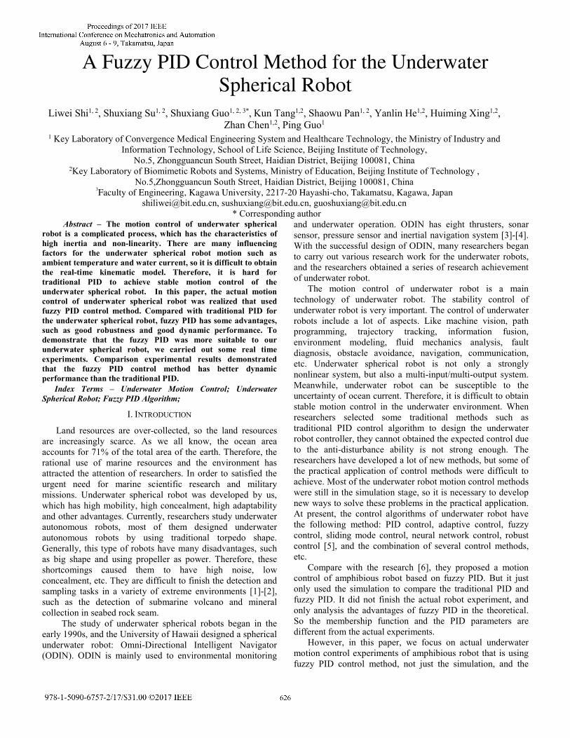
developed with high mobility and high hidden [7-8]. The application of a wide range of prospects, its application areas involving industry, fisheries, exploration, military, etc. The robot consists of a hemispherical body and four mechanical legs. As shown in Fig.1, the direction of the red line is the forward direction of the robot. The robot was equipped with a control system and a drive circuit in the upper hemisphere, and the robot has four two degrees of freedom mechanical legs in the lower hemisphere [9-12]. Each mechanical leg contains a water-jet thruster and two waterproof servo steering gears. Fixed in the horizontal and vertical bracket. The robot total diameter was 35 cm, and its weight in air was about 5.5 kg.
Forward Direction
Hemispherical
Body
Control System
Drive
Circuit
Fig.1 The amphibious spherical robot
The amphibious spherical robot have two model: the land mode and the underwater mode. The robot walked with four legs in the land mode, and it could drive with four water-jet thrusters in the underwater mode. The two mode as shown as in Fig.2, and this paper mainly studied the underwater motion control mode of robot.
Four LegsFour Water-jet
Thrusters
w
(a) Land mode (b) Underwater mode
Fig.2 The motion mode of the amphibious spherical robot
B. Dynamics equations of underwater spherical robot In order to achieve a more effective control strategy,
modeling of the underwater spherical robot is important. The generalized position and velocity are defined in six degrees of freedom (6-DOF) [13], which are usually defined as:
T 6[ , , , , , ]v u v w p q r= ∈ R (1)
T 3 3[ , , , , , ]x y zη φ θ ϕ= ∈ ×R S (2)
[ ] 3, ,T
p q rω = ∈ R (3)
[ ] 3, ,Tφ θ ψΘ = ∈S (4)
where R3 is n-dimensional Euclidean space, S3 is a three-dimensional torus. When modeling the movement of a six-degree-of-freedom underwater robot, by two reference coordinate systems and using the vector defined in equation (1) to (4) were used to describe the information of position, direction, velocity, angular velocity, etc.
In order to calculate the position and direction of the robot. It’s necessary to know the line acceleration and angular acceleration of the robot. It’s clear that these accelerations are determined by the forces acting on the robot. So the dynamics of the robot can be divided into two parts: rigid body and torque, hydrodynamic and torque [14].
Firstly, rigid body and torque satisfy the following equation:
( )RB RB HM v C v v τ+ = (5)
where: MRB is the robot inertia matrix, MA is the added mass inertia matrix, CRB(v) is Coriolis of robot, τH includes the total hydrodynamic force and torque including the load and controls the propulsion and torque.
Secondly, hydrodynamic and torque satisfy the following equation:
( ) ( ( )) ( )H A A l qM v C v v D D v v gτ τ= − − − + − Θ + (6)
where CA(v) is Coriolis of added mass, Dl is the linear damping matrix, Dq is the nonlinear damping matrix, g(Θ) is the restoring force and moment vector, τ is control vector.
Finally, substituting equation (5) into equation (6). The total underwater spherical robot dynamics equation can be expressed as:
( ) ( ( ) ( ))
( ( )) ( )RB A RB A
l q
M M v C v C v v
D D v v g τ+ + +
+ + + Θ =
(7)
In order to simplify the dynamics of underwater spherical robot model, the dynamics of the underwater spherical robot are declared as follows: (1) The velocity of underwater spherical robot is less than 1m/s; (2) During all experiments, the underwater spherical robot always hold in a horizontal attitude; (3) The x and y directions of the underwater spherical robot have the same dynamic characteristics on the xy plane. (4) The degree of freedom of the underwater spherical robot can be decoupled [15]; As the underwater spherical robot is considered to be symmetrically distributed, and the robot is moving at low velocity, and the decoupling of the freedom degree of the robot is well founded. Decoupling means that the Coriolis
force and the centripetal force become negligible and can be eliminated from the dynamics model. Therefore, simplified dynamics model of the underwater spherical robot can be obtained:
( ) ( ( )) ( )RB A l qM M v D D v v g τ+ + + + Θ = (8)
The specific dynamics model of the underwater spherical robot in the XY plane can be expressed as:
4
4
4
9.408 0 0 10.3 0 00 9.408 0 0 10.3 00 0 0.0826 0 0 0.065
1.01 10 0 0 0.471 0 00 1.01 10 0 0 0.4710
0 0 00 0 1.01 10
v
v τ
−
−
−
+ +
×× + =
×
(9)
The transfer function of the turn bow motion is: 40.1476 1.01 10 rr r τ−+ × = (10)
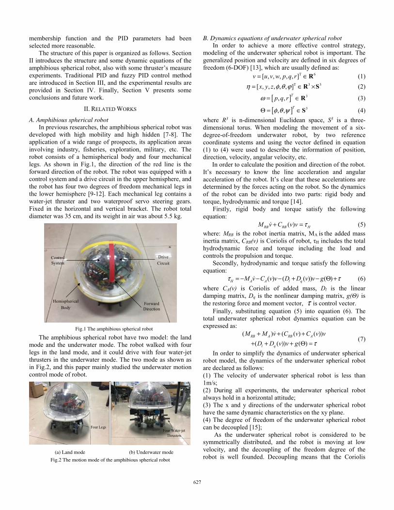
C. Identification of water-jet thruster In order to identify the dynamic characteristics of water-
jet thruster. According to the lever principle, a method of measuring the relationship between the input voltage and the output force of the water-jet thruster could be established. As shown in Fig.3 and Fig.4, the experimental device consisted of the angle ruler and fixed mechanism.
Thruster
mg
FL
FG
Ft
Ψ
Fig.3 The schematic diagram of experiment
Fig.4 Experimental setup
Using the lever principle, the relationship between the input voltage and output force can be expressed as the following equation:
sintF mg ψ= ⋅ (11)
where ψ is the deflection angle of lever, m is the quality of
underwater spherical robot, g is the gravity.
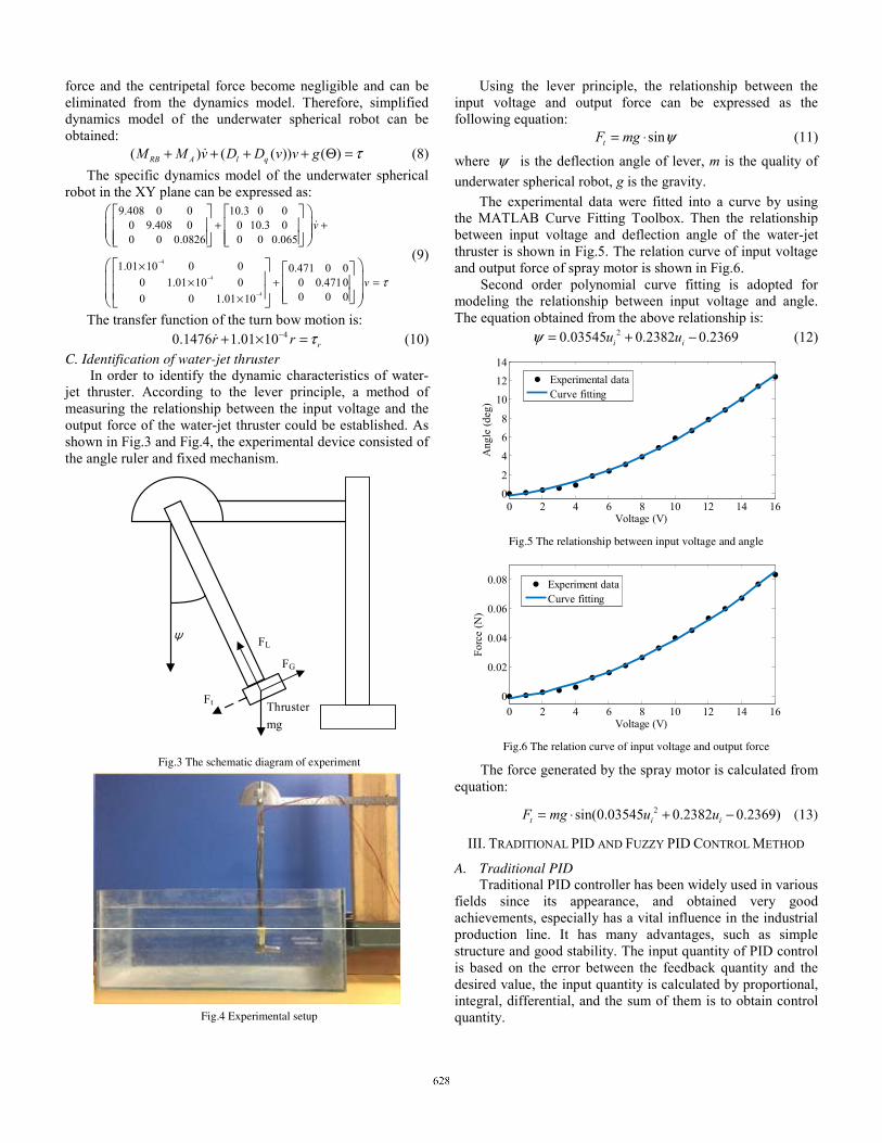
The experimental data were fitted into a curve by using the MATLAB Curve Fitting Toolbox. Then the relationship between input voltage and deflection angle of the water-jet thruster is shown in Fig.5. The relation curve of input voltage and output force of spray motor is shown in Fig.6. Second order polynomial curve fitting is adopted for modeling the relationship between input voltage and angle. The equation obtained from the above relationship is:
20.03545 0.2382 0.2369i iu uψ = + − (12)
0 2 4 6 8 10 12 14 160
2
4
6
8
10
12
14
Voltage (V)
Ang
le (
deg)
Experimental dataCurve fitting
Fig.5 The relationship between input voltage and angle
0 2 4 6 8 10 12 14 160
0.02
0.04
0.06
0.08
Voltage (V)
Forc
e (N
)
Experiment dataCurve fitting
Fig.6 The relation curve of input voltage and output force
The force generated by the spray motor is calculated from equation:
2sin(0.03545 0.2382 0.2369)t i iF mg u u= ⋅ + − (13)
III. TRADITIONAL PID AND FUZZY PID CONTROL METHOD
A. Traditional PID Traditional PID controller has been widely used in various
fields since its appearance, and obtained very good achievements, especially has a vital influence in the industrial production line. It has many advantages, such as simple structure and good stability. The input quantity of PID control is based on the error between the feedback quantity and the desired value, the input quantity is calculated by proportional, integral, differential, and the sum of them is to obtain control quantity.
Generally, traditional PID is suitable for linear systems. Block diagram of traditional PID control system is shown in Fig.7.
PID Controller
Water-jet Thrusters
expectd angle
measured angle
-
IMU
error PWM
Fig.7 Block diagram of traditional PID control system
PID controller control law is:
0
1 ( )( ) ( ) ( )
( )( ) ( )
t
p di
t
p i do
de tu t K e t e t dt T
T dt
de tK e t K e t dt K
dt
= + +
= + +
(14)
where Kp is proportional gain coefficient, Ki is integral coefficient, Kd is differential coefficient, e(t) is error. B. Fuzzy PID
Fuzzy PID controller consists of two parts: fuzzy module and traditional PID controller. The main task of fuzzy PID controller is to detect the error and the rate of error of the system at each sampling period continuously, and it can obtain the correction quantity of PID parameters according to fuzzy rules. Then, the control quantity of the system is obtained by calculation of the PID controller. Fuzzy PID can improve performance and robustness of system by the tuning of PID parameters at real-time, and increase the anti-interference of the system. Block diagram of the fuzzy PID controller system is shown in Fig.8.
PID Controller
Fuzzy Inference
Water-jet Thrusters
IMU
errorexcepted
angle
mearsured angle
-de—dt
PWM
Fig.8 Block diagram of fuzzy PID controller system
The design of fuzzy PID controller can be divided into three step as follows:
(1) First step, the fuzzy of input and output variables: We select the robot’s yawing angle error (e) and its rate of
change (ec) as the input variables of the fuzzy PID controller. After the input variables are calculated by the quantization factor, we enter them to the fuzzy controller and get the blurring variable (E and Ec). The output of fuzzy variables are Kp, Ki and Kd. The fuzzy domain and membership functions of input and output variables are shown in Fig.9 (a) to Fig.9 (e).
(2) Second step, the design of fuzzy rules: Generally in different cases, the principle of setting of PID parameters as follows: 1) When the value of |E| is big, we need to increase the value of Kp so that the |E| can decrease quickly, and we need to decrease the value of Kd that can void the fast increase of differential action.
2) When the value of |E| and the |Ec| are medium, we need to decrease the value of Kp and Ki that can avoid the overshoot. 3) When the value of |E| is small, we need to increase the value of Kp and Ki that can decrease the steady-state error. To avoid instability in the vicinity of the steady-state value of the system, and the dynamic performance of the system will be greatly affected by the value of Kd, so we need to find a suitable value of Kd. 4) The error rate of change of system is decided by the value of |Ec|, and when the value of | Ec | is big, we need to increase the value of Kp and decrease the value of Ki.
According to the above, the dynamic performance of system can be influenced by PID parameters, based on a large number of experimental data, we can obtain the excellent response performance of the system by setting the principle of fuzzy PID control parameters rules, and the fuzzy rules of Kp have shown in Table II. Fuzzy rules of the other parameters can be analogy.
(a) The membership function of E (b) The membership function of Ec
(c) The membership function of Kp (d) The membership function of Ki
(e) The membership function of Kd
Fig.9 The membership functions of variables
TABLE II FUZZY RULES OF KP
NB NM NS ZO PS PM PB
NB NB NB NM ZO ZO ZO PS
NM NB NM NM ZO Z0 PS PS
NS NM NM NS PS PS PS PM
ZO NM NM NS PS PS PM PM
PS NM NS NS PM PM PM PB
PM NS NS ZO PM PM PB PB
PB ZO ZO ZO PB PB PB PB
EcE
(3) Third step, fuzzy inference and defuzzification: According to the fuzzy fules, the fuzzy value output of
Kp, Ki and Kd are obtained by fuzzy inference and defuzzification. The membership degree of the first fuzzy rule corresponding to Kp is:
{ }1 min ( ), ( )Kp NB NBm m E m EC= (15)
The rest can be done in the same manner, we can obtain the membership degree of all fuzzy rules are corresponded to the output of Kp at different error and error rate of change. According to fuzzy rules, the fuzzy value of output of Kp can be defuzzification by using the weighted average method:
kpj pjp
kpj
m KK
mΔ =
(16)
where Kpj is the real number of domain of Kp. Similarly, we can obtain the fuzzy output value of Ki and Kd in each sampling period. But these values are still fuzzy values, we need to multiply these values by the scale factor so that we can obtain the actual control output value of Kp, Ki and Kd, and the PID controller parameters can be updated. The adjustment algorithm is:
0
0
0
p p p
i i i
d d d
K K D K
K K D K
K K D K
= + ∗Δ
= + ∗ Δ= + ∗Δ
(17)
where D is the scale factor.
IV. EXPERIMENTS AND RESULTS
In this section, we carried out some experiments to demonstrate that the fuzzy PID is more suitable to our underwater spherical robot.
X
Y
Z
(a) At 0s (b) At 8s
(c) At 16s (d) At 24s
Fig.10 Straight forward motion (Traditional PID)
Fig.10 shows a video sequence of the forward motion and the totally horizontal forward motion spent about twenty-five second. In Fig.10, There were two rulers about two meter in the vertical direction of the pool and a ruler about two point five meter in the horizontal direction of the pool. We carried
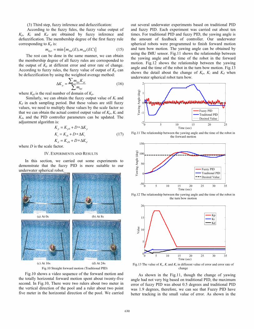
out several underwater experiments based on traditional PID and fuzzy PID. Each experiment was carried out about ten times. For traditional PID and fuzzy PID, the yawing angle is the amount of feedback of controller. Our underwater spherical robots were programmed to finish forward motion and turn bow motion. The yawing angle can be obtained by using the IMU sensor. Fig.11 shows the relationship between the yawing angle and the time of the robot in the forward motion. Fig.12 shows the relationship between the yawing angle and the time of the robot in the turn bow motion. Fig.13 shows the detail about the change of Kp, Ki and Kd when underwater spherical robot turn bow.
0 5 10 15 20 25-2
-1
0
1
2
Time (sec)
Yaw
ing
Ang
le (
deg)
Fuzzy PIDTraditonal PIDDesired Value
Fig.11 The relationship between the yawing angle and the time of the robot in
the forward motion
0 5 10 15 20 25 30 35-50
0
50
100
150
Time (sec)
Yaw
ing
Ang
le (
deg)
Fuzzy PIDTraditonal PIDDesired Value
Fig.12 The relationship between the yawing angle and the time of the robot in
the turn bow motion
0 5 10 15 20 25 30 350
5
10
15
20
Time (sec)
Val
ue
KpKiKd
Fig.13 The value of Kp, Ki and Kd in different value of error and error rate of
change
As shown in the Fig.11, though the change of yawing angle had not very big based on traditional PID, the maximum error of fuzzy PID was about 0.5 degrees and traditional PID was 1.9 degrees, therefore, we can see that Fuzzy PID have better tracking in the small value of error. As shown in the
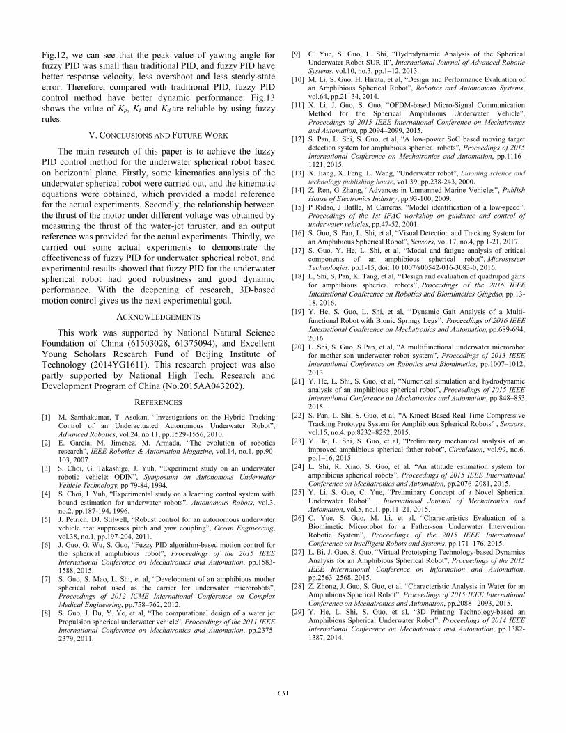
Fig.12, we can see that the peak value of yawing angle for fuzzy PID was small than traditional PID, and fuzzy PID have better response velocity, less overshoot and less steady-state error. Therefore, compared with traditional PID, fuzzy PID control method have better dynamic performance. Fig.13 shows the value of Kp, Ki and Kd are reliable by using fuzzy rules.
V. CONCLUSIONS AND FUTURE WORK
The main research of this paper is to achieve the fuzzy PID control method for the underwater spherical robot based on horizontal plane. Firstly, some kinematics analysis of the underwater spherical robot were carried out, and the kinematic equations were obtained, which provided a model reference for the actual experiments. Secondly, the relationship between the thrust of the motor under different voltage was obtained by measuring the thrust of the water-jet thruster, and an output reference was provided for the actual experiments. Thirdly, we carried out some actual experiments to demonstrate the effectiveness of fuzzy PID for underwater spherical robot, and experimental results showed that fuzzy PID for the underwater spherical robot had good robustness and good dynamic performance. With the deepening of research, 3D-based motion control gives us the next experimental goal.
ACKNOWLEDGEMENTS
This work was supported by National Natural Science Foundation of China (61503028, 61375094), and Excellent Young Scholars Research Fund of Beijing Institute of Technology (2014YG1611). This research project was also partly supported by National High Tech. Research and Development Program of China (No.2015AA043202).
REFERENCES
[1] M. Santhakumar, T. Asokan, “Investigations on the Hybrid Tracking Control of an Underactuated Autonomous Underwater Robot”, Advanced Robotics, vol.24, no.11, pp.1529-1556, 2010.
[2] E. Garcia, M. Jimenez, M. Armada, “The evolution of robotics research”, IEEE Robotics & Automation Magazine, vol.14, no.1, pp.90-103, 2007.
[3] S. Choi, G. Takashige, J. Yuh, “Experiment study on an underwater robotic vehicle: ODIN”, Symposium on Autonomous Underwater Vehicle Technology, pp.79-84, 1994.
[4] S. Choi, J. Yuh, “Experimental study on a learning control system with bound estimation for underwater robots”, Autonomous Robots, vol.3, no.2, pp.187-194, 1996.
[5] J. Petrich, DJ. Stilwell, “Robust control for an autonomous underwater vehicle that suppresses pitch and yaw coupling”, Ocean Engineering, vol.38, no.1, pp.197-204, 2011.
[6] J. Guo, G. Wu, S. Guo, “Fuzzy PID algorithm-based motion control for the spherical amphibious robot”, Proceedings of the 2015 IEEE International Conference on Mechatronics and Automation, pp.1583-1588, 2015.
[7] S. Guo, S. Mao, L. Shi, et al, “Development of an amphibious mother spherical robot used as the carrier for underwater microrobots”, Proceedings of 2012 ICME International Conference on Complex Medical Engineering, pp.758–762, 2012.
[8] S. Guo, J. Du, Y. Ye, et al, “The computational design of a water jet Propulsion spherical underwater vehicle”, Proceedings of the 2011 IEEE International Conference on Mechatronics and Automation, pp.2375-2379, 2011.
[9] C. Yue, S. Guo, L. Shi, “Hydrodynamic Analysis of the Spherical Underwater Robot SUR-II”, International Journal of Advanced Robotic Systems, vol.10, no.3, pp.1–12, 2013.
[10] M. Li, S. Guo, H. Hirata, et al, “Design and Performance Evaluation of an Amphibious Spherical Robot”, Robotics and Autonomous Systems, vol.64, pp.21–34, 2014.
[11] X. Li, J. Guo, S. Guo, “OFDM-based Micro-Signal Communication Method for the Spherical Amphibious Underwater Vehicle”, Proceedings of 2015 IEEE International Conference on Mechatronics and Automation, pp.2094–2099, 2015.
[12] S. Pan, L. Shi, S. Guo, et al, “A low-power SoC based moving target detection system for amphibious spherical robots”, Proceedings of 2015 International Conference on Mechatronics and Automation, pp.1116–1121, 2015.
[13] X. Jiang, X. Feng, L. Wang, “Underwater robot”, Liaoning science and technology publishing house, vo1.39, pp.238-243, 2000.
[14] Z. Ren, G Zhang, “Advances in Unmanned Marine Vehicles”, Publish House of Electronics Industry, pp.93-100, 2009.
[15] P Ridao, J Batlle, M Carreras, “Model identification of a low-speed”, Proceedings of the 1st IFAC workshop on guidance and control of underwater vehicles, pp.47-52, 2001.
[16] S. Guo, S. Pan, L. Shi, et al, “Visual Detection and Tracking System for an Amphibious Spherical Robot”, Sensors, vol.17, no.4, pp.1-21, 2017.
[17] S. Guo, Y. He, L. Shi, et al, “Modal and fatigue analysis of critical components of an amphibious spherical robot”, Microsystem Technologies, pp.1-15, doi: 10.1007/s00542-016-3083-0, 2016.
[18] L, Shi, S, Pan, K. Tang, et al, ‘‘Design and evaluation of quadruped gaits for amphibious spherical robots’’, Proceedings of the 2016 IEEE International Conference on Robotics and Biomimetics Qingdao, pp.13-18, 2016.
[19] Y. He, S. Guo, L. Shi, et al, ‘‘Dynamic Gait Analysis of a Multi-functional Robot with Bionic Springy Legs’’, Proceedings of 2016 IEEE International Conference on Mechatronics and Automation, pp.689-694, 2016.
[20] L. Shi, S. Guo, S Pan, et al, “A multifunctional underwater microrobot for mother-son underwater robot system”, Proceedings of 2013 IEEE International Conference on Robotics and Biomimetics, pp.1007–1012, 2013.
[21] Y. He, L. Shi, S. Guo, et al, “Numerical simulation and hydrodynamic analysis of an amphibious spherical robot”, Proceedings of 2015 IEEE International Conference on Mechatronics and Automation, pp.848–853, 2015.
[22] S. Pan, L. Shi, S. Guo, et al, “A Kinect-Based Real-Time Compressive Tracking Prototype System for Amphibious Spherical Robots” , Sensors, vol.15, no.4, pp.8232–8252, 2015.
[23] Y. He, L. Shi, S. Guo, et al, “Preliminary mechanical analysis of an improved amphibious spherical father robot”, Circulation, vol.99, no.6, pp.1–16, 2015.
[24] L. Shi, R. Xiao, S. Guo, et al. “An attitude estimation system for amphibious spherical robots”, Proceedings of 2015 IEEE International Conference on Mechatronics and Automation, pp.2076–2081, 2015.
[25] Y. Li, S. Guo, C. Yue, “Preliminary Concept of a Novel Spherical Underwater Robot” , International Journal of Mechatronics and Automation, vol.5, no.1, pp.11–21, 2015.
[26] C. Yue, S. Guo, M. Li, et al, “Characteristics Evaluation of a Biomimetic Microrobot for a Father-son Underwater Intervention Robotic System”, Proceedings of the 2015 IEEE International Conference on Intelligent Robots and Systems, pp.171–176, 2015.
[27] L. Bi, J. Guo, S. Guo, “Virtual Prototyping Technology-based Dynamics Analysis for an Amphibious Spherical Robot”, Proceedings of the 2015 IEEE International Conference on Information and Automation, pp.2563–2568, 2015.
[28] Z. Zhong, J. Guo, S. Guo, et al, “Characteristic Analysis in Water for an Amphibious Spherical Robot”, Proceedings of 2015 IEEE International Conference on Mechatronics and Automation, pp.2088– 2093, 2015.
[29] Y. He, L. Shi, S. Guo, et al, “3D Printing Technology-based an Amphibious Spherical Underwater Robot”, Proceedings of 2014 IEEE International Conference on Mechatronics and Automation, pp.1382-1387, 2014.


![[PID] PID Control - Good Tuning - A Pocket Guide](https://static.fdocuments.us/doc/165x107/577d2a661a28ab4e1ea914b1/pid-pid-control-good-tuning-a-pocket-guide.jpg)


