PID INSTRUCTIONOPENNET CONTROLLER PID INSTRUCTION USER’S MANUAL 1 PID INSTRUCTION Introduction The...
18
April 22, 2002 OPENNET CONTROLLER PID INSTRUCTION
Transcript of PID INSTRUCTIONOPENNET CONTROLLER PID INSTRUCTION USER’S MANUAL 1 PID INSTRUCTION Introduction The...

April 22, 2002
OPENNET CONTROLLER
PID INSTRUCTION

PID INSTRUCTION
IntroductionThe PID instruction implements a PID (proportional, integral, and derivative) algorithm with built-in auto tuning to deter-mine PID parameters, such as proportional gain, integral time, derivative time, and control action automatically. The PID instruction is primarily designed for use with an analog I/O module to read analog input data, and turns on and off a desig-nated output to perform PID control in applications such as temperature control described in the application example on page 14. In addition, when the output manipulated variable is converted, the PID instruction can also generate an analog output using an analog I/O module.
PID (PID Control)
Valid Operands
Source operand S1 (control register) uses 27 data registers starting with the operand designated as S1. Data registers D0 through D7973 can be designated as S1. For details, see the following pages.
Source operand S2 (control relay) uses 8 points of outputs or internal relays starting with the operand designated as S2. Outputs Q0 through Q590 or internal relays M0 through M2550 can be designated as S2. For details, see page 10.
Source operand S3 (set point): When the linear conversion is disabled (S1+4 set to 0), the valid range of the set point (S3) is 0 through 4000 which can be designated using a data register or constant. When the linear conversion is enabled (S1+4 set to 1), the valid range is –32768 to 32767 that is a value after linear conversion. Use a data register to designate a nega-tive value for a set point when the linear conversion is used. For details, see page 12.
Source operand S4 (process variable) is designated using a data register or link register. When reading input data from an analog input module, designate a proper link register number depending on the slot position of the analog input module and the channel number connected to the analog input. For details, see page 12.
Destination operand D1 (manipulated variable) stores –32768 through 32767 that is a calculation result of the PID action. For details, see page 13.
Operand Function I Q M R T C D L Constant
S1 (Source 1) Control register — — — — — — D0-D7973 — —
S2 (Source 2) Control relay — Q0-Q590 M0-M2550 — — — — — —
S3 (Source 3) Set point — — — — — — D0-D7999 — 0-4000
S4 (Source 4)Process variable(before conversion)
— — — — — — D0-D7999 L100-L705 —
D1 (Destination 1) Manipulated variable — — — — — — D0-D7999 — —
• Special technical knowledge about the PID control is required to use the PID function of the OpenNet Controller. Use of the PID function without understanding the PID control may cause the OpenNet Controller to perform unexpected operation, resulting in disorder of the control sys-tem, damage, or accidents.
• When using the PID instruction for feedback control, emergency stop and interlocking circuits must be configured outside the OpenNet Controller. If such a circuit is configured inside the OpenNet Controller, failure of inputting the process variable may cause equipment damage or accidents.
Warning
When input is on, auto tuning and/or PID action is exe-cuted according to the value (0 through 2) stored in a data register operand assigned for operation mode.
A maximum of 42 PID instructions can be used in a user program.
D1*****
S1*****
PID S2*****
S3*****
S4*****
OPENNET CONTROLLER PID INSTRUCTION USER’S MANUAL 1

PID INSTRUCTION
Source Operand S1 (Control Register)Store appropriate values to data registers starting with the operand designated by S1 before executing the PID instruction as required, and make sure that the values are within the valid range. Operands S1+0 through S1+2 are for read only, and operands S1+23 through S1+26 are reserved for the system program.
Note: The value stored in the data register designated by S1+3 (operation mode) is checked only when the start input for the PID instruction is turned on. Values in all other control registers are refreshed in every scan.
Operand Function Description R/W
S1+0Process variable(after conversion)
When S1+4 (linear conversion) = 1 (enable linear conversion): Stores the process variable after conversion.When S1+4 (linear conversion) = 0 (disable linear conversion): Stores the process variable without conversion.
R
S1+1 Output manipulated variableStores the output manipulated variable (manual mode output variable and AT output manipulated variable) in percent.0 to 100 (0% to 100%)
R
S1+2 Operating status Stores the operating or error status of the PID instruction. R
S1+3 Operation mode0: PID action1: AT (auto tuning) + PID action2: AT (auto tuning)
R/W
S1+4 Linear conversion0: Disable linear conversion1: Enable linear conversion
R/W
S1+5Linear conversion maximum value
–32768 to +32767 R/W
S1+6Linear conversion minimum value
–32768 to +32767 R/W
S1+7 Proportional gain1 to 10000 (0.01% to 100.00%)0 designates 0.01%, ≥10001 designates 100.00%
R/W
S1+8 Integral time 1 to 65535 (0.1 sec to 6553.5 sec), 0 disables integral action R/W
S1+9 Derivative time 1 to 65535 (0.1 sec to 6553.5 sec), 0 disables derivative action R/W
S1+10 Integral start coefficient1 to 100 (1% to 100%), 0 and ≥101 (except 200) designate 100%200 executes integral action within the proportional range
R/W
S1+11 Input filter coefficient 0 to 99 (0% to 99%), ≥100 designates 99% R/W
S1+12 Sampling period1 to 10000 (0.01 sec to 100.00 sec)0 designates 0.01 sec, ≥10001 designates 100.00 sec
R/W
S1+13 Control period1 to 500 (0.1 sec to 50.0 sec)0 designates 0.1 sec, ≥501 designates 50.0 sec
R/W
S1+14 High alarm value
When S1+4 (linear conversion) = 0: 0 to 4000 (≥4001 designates 4000)When S1+4 = 1: Linear conversion min. ≤ High alarm ≤ Linear conversion max.When S1+14 < S1+6 (linear conversion min.), S1+6 becomes high alarm.When S1+14 > S1+5 (linear conversion max.), S1+5 becomes high alarm.
R/W
S1+15 Low alarm value
When S1+4 (linear conversion) = 0: 0 to 4000 (≥4001 designates 4000)When S1+4 = 1: Linear conversion min. ≤ Low alarm ≤ Linear conversion max.When S1+15 < S1+6 (linear conversion min.), S1+6 becomes low alarm.When S1+15 > S1+5 (linear conversion max.), S1+5 becomes low alarm.
R/W
S1+16Output manipulated variable upper limit
0 to 100, 10001 to 10099 (other values designate 100) R/W
S1+17Output manipulated variable lower limit
0 to 100 (≥101 designates 100) R/W
S1+18Manual mode output manipulated variable
0 to 100 (≥101 designates 100) R/W
S1+19 AT sampling period1 to 10000 (0.01 sec to 100.00 sec)0 designates 0.01 sec, ≥10001 designates 100.00 sec
R/W
S1+20 AT control period1 to 500 (0.1 sec to 50.0 sec)0 designates 0.1 sec, ≥501 designates 50.0 sec
R/W
S1+21 AT set pointWhen S1+4 (linear conversion) = 0: 0 to 4000 (≥4001 designates 4000)When S1+4 = 1: Linear conversion min. ≤ AT set point ≤ Linear conversion max.
R/W
S1+22 AT output manipulated variable 0 to 100 (≥101 designates 100) R/W
S1+23S1+24S1+25S1+26
— Reserved for processing the PID instruction —
OPENNET CONTROLLER PID INSTRUCTION USER’S MANUAL 2

PID INSTRUCTION
S1+0 Process Variable (after conversion)
When the linear conversion is enabled (S1+4 set to 1), the data register designated by operand S1+0 stores the linear con-version result of the process variable designated by operand S4. The process variable (S1+0) takes a value between the lin-ear conversion minimum value (S1+6) and the linear conversion maximum value (S1+5).
When the linear conversion is disabled (S1+4 is set to 0), the data register designated by operand S1+0 stores the same value as the process variable designated by operand S4.
S1+1 Output Manipulated Variable
While the PID action is in progress, the data register designated by operand S1+1 holds 0 through 100 read from the manipulated variable, –32768 through 32767, stored in the data register designated by operand D1, omitting values less than 0 and greater than 100. The percent value in S1+1 determines the ON duration of the control output (S2+6) in propor-tion to the control period (S1+13).
While manual mode is enabled with the auto/manual mode control relay (S2+1) set to on, S1+1 stores 0 through 100 read from the manual mode output manipulated variable (S1+18).
While auto tuning (AT) is in progress, S1+1 stores 0 through 100 read from the AT output manipulated variable (S1+22).
S1+2 Operating Status
The data register designated by operand S1+2 stores the operating or error status of the PID instruction.
Status codes 1X through 6X contain the time elapsed after starting auto tuning or PID action. X changes from 0 through 9 in 10-minute increments to represent 0 through 90 minutes. The time code remains 9 after 90 minutes has elapsed. When the operation mode (S1+3) is set to 1 (AT+PID), the time code is reset to 0 at the transition from AT to PID.
Status codes 100 and above indicate an error, stopping the auto tuning or PID action. When these errors occur, a user pro-gram execution error will result, turning on the ERR LED and special internal relay M8004 (user program execution error). To continue operation, enter correct parameters and turn on the start input for the PID instruction.
Status Code Description Operation
1X AT in progressAT is normal.
2X AT completed
5X PID action in progressPID action is normal.
6XPID set point (S3) is reached. Status code changes from 5X to 6X once the PID set point is reached.
100 The operation mode (S1+3) is set to a value over 2.
PID action or AT is stopped because of incorrect parameter settings.
101 The linear conversion (S1+4) is set to a value over 1.
102When the linear conversion is enabled (S1+4 to 1), the linear conversion maximum value (S1+5) and the linear conversion minimum value (S1+6) are set to the same value.
103The output manipulated variable upper limit (S1+16) is set to a value smaller than the out-put manipulated variable lower limit (S1+17).
104When the linear conversion is enabled (S1+4 set to 1), the AT set point (S1+21) is set to a value larger than the linear conversion maximum value (S1+5) or smaller than the linear con-version minimum value (S1+6).
105When the linear conversion is disabled (S1+4 set to 0), the AT set point (S1+21) is set to a value larger than 4000.
106When the linear conversion is enabled (S1+4 set to 1), the set point (S3) is set to a value larger than the linear conversion maximum value (S1+5) or smaller than the linear conver-sion minimum value (S1+6).
107When the linear conversion is disabled (S1+4 set to 0), the set point (S3) is set to a value larger than 4000.
200
The current control action (S2+0) differs from that determined at the start of AT. To restart AT, set correct parameters referring to the probable causes listed below:• The manipulated variable (D1) or the control output (S2+6) is not outputted to the control target correctly.• The process variable is not stored to the operand designated by S4.• The AT output manipulated variable (S1+22) is not set to a large value so that the process variable (S4) can change sufficiently.• A large disturbance occurred.
AT is stopped because of AT execution error.
201AT failed to complete normally because the process variable (S4) fluctuated excessively. To restart AT, set the AT sampling period (S1+19) or the input filter coefficient (S1+11) to a larger value.
OPENNET CONTROLLER PID INSTRUCTION USER’S MANUAL 3
PID INSTRUCTION
S1+3 Operation Mode
When the start input for the PID instruction is turned on, the CPU module checks the value stored in the data register des-ignated by S1+3 and executes the selected operation. The selection cannot be changed while executing the PID instruction.
0: PID actionThe PID action is executed according to the designated PID parameters such as proportional gain (S1+7), integral time (S1+8), derivative time (S1+9), and control action (S2+0).
1: AT (auto tuning) + PID actionAuto tuning is first executed according to the designated AT parameters such as AT sampling period (S1+19), AT con-trol period (S1+20), AT set point (S1+21), and AT output manipulated variable (S1+22). As a result of auto tuning, PID parameters are determined such as proportional gain (S1+7), integral time (S1+8), derivative time (S1+9), and control direction (S2+0), then PID action is executed according to the derived PID parameters.
2: AT (auto tuning)Auto tuning is executed according to designated AT parameters to determine PID parameters such as proportional gain (S1+7), integral time (S1+8), derivative time (S1+9), and control direction (S2+0); PID action is not executed.
S1+4 Linear Conversion
0: Disable linear conversionLinear conversion is not executed. When the linear conversion is disabled (S1+4 set to 0), the analog input data (0 through 4000) from the analog I/O module is stored to the process variable (S4), and the same value is stored to the process variable (S1+0) without conversion.
1: Enable linear conversionThe linear conversion function is useful for scaling the process variable to the actual measured value in engineering units.
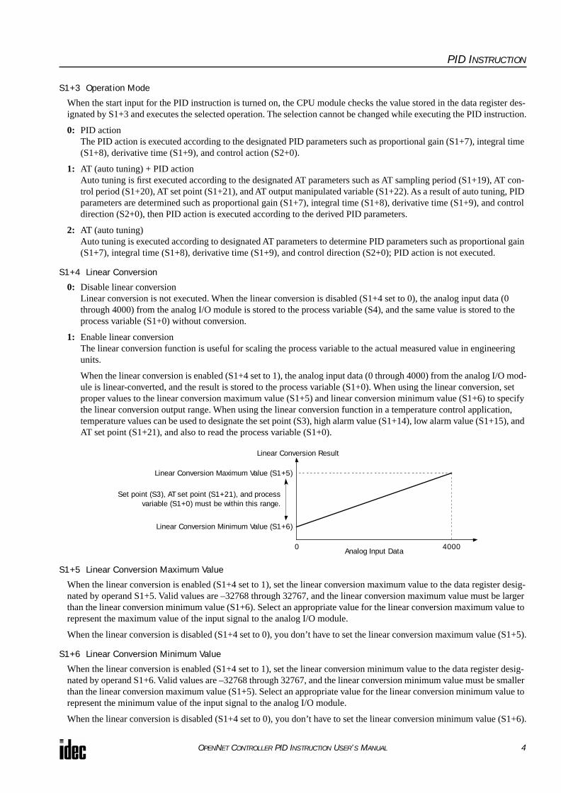
When the linear conversion is enabled (S1+4 set to 1), the analog input data (0 through 4000) from the analog I/O mod-ule is linear-converted, and the result is stored to the process variable (S1+0). When using the linear conversion, set proper values to the linear conversion maximum value (S1+5) and linear conversion minimum value (S1+6) to specify the linear conversion output range. When using the linear conversion function in a temperature control application, temperature values can be used to designate the set point (S3), high alarm value (S1+14), low alarm value (S1+15), and AT set point (S1+21), and also to read the process variable (S1+0).
S1+5 Linear Conversion Maximum Value
When the linear conversion is enabled (S1+4 set to 1), set the linear conversion maximum value to the data register desig-nated by operand S1+5. Valid values are –32768 through 32767, and the linear conversion maximum value must be larger than the linear conversion minimum value (S1+6). Select an appropriate value for the linear conversion maximum value to represent the maximum value of the input signal to the analog I/O module.
When the linear conversion is disabled (S1+4 set to 0), you don’t have to set the linear conversion maximum value (S1+5).
S1+6 Linear Conversion Minimum Value
When the linear conversion is enabled (S1+4 set to 1), set the linear conversion minimum value to the data register desig-nated by operand S1+6. Valid values are –32768 through 32767, and the linear conversion minimum value must be smaller than the linear conversion maximum value (S1+5). Select an appropriate value for the linear conversion minimum value to represent the minimum value of the input signal to the analog I/O module.
When the linear conversion is disabled (S1+4 set to 0), you don’t have to set the linear conversion minimum value (S1+6).
Linear Conversion Result
0Analog Input Data
Linear Conversion Maximum Value (S1+5)
Linear Conversion Minimum Value (S1+6)
4000
Set point (S3), AT set point (S1+21), and processvariable (S1+0) must be within this range.
OPENNET CONTROLLER PID INSTRUCTION USER’S MANUAL 4
PID INSTRUCTION
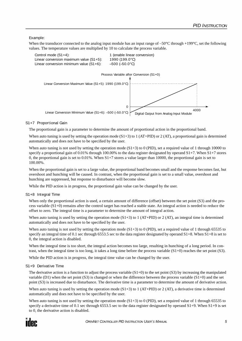
Example:When the transducer connected to the analog input module has an input range of –50°C through +199°C, set the following values. The temperature values are multiplied by 10 to calculate the process variable.
Control mode (S1+4): 1 (enable linear conversion)Linear conversion maximum value (S1+5): 1990 (199.0°C)Linear conversion minimum value (S1+6): –500 (–50.0°C)
S1+7 Proportional Gain
The proportional gain is a parameter to determine the amount of proportional action in the proportional band.
When auto tuning is used by setting the operation mode (S1+3) to 1 (AT+PID) or 2 (AT), a proportional gain is determined automatically and does not have to be specified by the user.
When auto tuning is not used by setting the operation mode (S1+3) to 0 (PID), set a required value of 1 through 10000 to specify a proportional gain of 0.01% through 100.00% to the data register designated by operand S1+7. When S1+7 stores 0, the proportional gain is set to 0.01%. When S1+7 stores a value larger than 10000, the proportional gain is set to 100.00%.
When the proportional gain is set to a large value, the proportional band becomes small and the response becomes fast, but overshoot and hunching will be caused. In contrast, when the proportional gain is set to a small value, overshoot and hunching are suppressed, but response to disturbance will become slow.
While the PID action is in progress, the proportional gain value can be changed by the user.
S1+8 Integral Time
When only the proportional action is used, a certain amount of difference (offset) between the set point (S3) and the pro-cess variable (S1+0) remains after the control target has reached a stable state. An integral action is needed to reduce the offset to zero. The integral time is a parameter to determine the amount of integral action.
When auto tuning is used by setting the operation mode (S1+3) to 1 (AT+PID) or 2 (AT), an integral time is determined automatically and does not have to be specified by the user.
When auto tuning is not used by setting the operation mode (S1+3) to 0 (PID), set a required value of 1 through 65535 to specify an integral time of 0.1 sec through 6553.5 sec to the data register designated by operand S1+8. When S1+8 is set to 0, the integral action is disabled.
When the integral time is too short, the integral action becomes too large, resulting in hunching of a long period. In con-trast, when the integral time is too long, it takes a long time before the process variable (S1+0) reaches the set point (S3).
While the PID action is in progress, the integral time value can be changed by the user.
S1+9 Derivative Time
The derivative action is a function to adjust the process variable (S1+0) to the set point (S3) by increasing the manipulated variable (D1) when the set point (S3) is changed or when the difference between the process variable (S1+0) and the set point (S3) is increased due to disturbance. The derivative time is a parameter to determine the amount of derivative action.
When auto tuning is used by setting the operation mode (S1+3) to 1 (AT+PID) or 2 (AT), a derivative time is determined automatically and does not have to be specified by the user.
When auto tuning is not used by setting the operation mode (S1+3) to 0 (PID), set a required value of 1 through 65535 to specify a derivative time of 0.1 sec through 6553.5 sec to the data register designated by operand S1+9. When S1+9 is set to 0, the derivative action is disabled.
Process Variable after Conversion (S1+0)
0
Digital Output from Analog Input Module
Linear Conversion Maximum Value (S1+5): 1990 (199.0°C)
Linear Conversion Minimum Value (S1+6): –500 (–50.0°C)4000
OPENNET CONTROLLER PID INSTRUCTION USER’S MANUAL 5

PID INSTRUCTION
When the derivative time is set to a large value, the derivative action becomes large. When the derivative action is too large, hunching of a short period is caused.
While the PID action is in progress, the derivative time value can be changed by the user.
S1+10 Integral Start Coefficient
The integral start coefficient is a parameter to determine the point, in percent of the proportional term, where to start the integral action. Normally, the data register designated by operand S1+10 (integral start coefficient) stores 0 to select an integral start coefficient of 100% and the integral start coefficient disable control relay (S2+3) is turned off to enable inte-gral start coefficient. When the PID action is executed according to the PID parameters determined by auto tuning, proper control is ensured with a moderate overshoot and no offset.
It is also possible to set a required value of 1 through 100 to start the integral action at 1% through 100% to the data regis-ter designated by operand S1+10. When S1+10 stores 0 or a value larger than 100 (except for 200), the integral start coef-ficient is set to 100%.
When 200 is set to S1+10, the integral action is enabled only while the process variable (S4) is within the proportional band. When the process variable runs off the proportional band due to disturbance or changing of the set point, the integral action is disabled, so that adjustment of the output manipulated variable (S1+1) is improved with little overshoot and undershoot.
To enable the integral start coefficient, turn off the integral start coefficient disable control relay (S2+3). When S2+3 is turned on, the integral start coefficient is disabled and the integral term takes effect at the start of the PID action.
When the integral term is enabled at the start of the PID action, a large overshoot is caused. The overshoot can be sup-pressed by delaying the execution of the integral action in coordination with the proportional term. The PID instruction is designed to achieve proper control with a small or moderate overshoot when the integral start coefficient is set to 100%. Overshoot is most suppressed when the integral start coefficient is set to 1% and is least suppressed when the integral start coefficient is set to 100%. When the integral start coefficient is too small, overshoot is eliminated but offset is caused.
S1+11 Input Filter Coefficient
The input filter has an effect to smooth out fluctuations of the process variable (S4). Set a required value of 0 through 99 to specify an input filter coefficient of 0% through 99% to the data register designated by operand S1+11. When S1+11 stores a value larger than 99, the input filter coefficient is set to 99%. The larger the coefficient, the larger the input filter effect.
The input filter is effective for reading a process variable (S4) such as temperature data when the value changes at each sampling time. The input filter coefficient is in effect during auto tuning and PID action.
S1+12 Sampling Period
The sampling period determines the interval to execute the PID instruction. Set a required value of 1 through 10000 to specify a sampling period of 0.01 sec through 100.00 sec to the data register designated by operand S1+12. When S1+12 stores 0, the sampling period is set to 0.01 sec. When S1+12 stores a value larger than 10000, the sampling period is set to 100.00 sec.
When a sampling period is set to a value smaller than the scan time, the PID instruction is executed every scan.
Example – Sampling period: 40 msec, Scan time: 80 msec (Sampling period ≤ Scan time)
1 scan
80 msec 80 msec 80 msec 80 msec 80 msec
PIDExecuted
PIDExecuted
PIDExecuted
PIDExecuted
PIDExecuted
PIDExecuted
1 scan 1 scan 1 scan 1 scan 1 scan
OPENNET CONTROLLER PID INSTRUCTION USER’S MANUAL 6

PID INSTRUCTION
Example – Sampling period: 80 msec, Scan time: 60 msec (Sampling period > Scan time)
S1+13 Control Period
The control period determines the duration of the ON/OFF cycle of the control output (S2+6) that is turned on and off according to the output manipulated variable (S1+1) calculated by the PID action or derived from the manual mode output manipulated variable (S1+18). Set a required value of 1 through 500 to specify a control period of 0.1 sec through 50.0 sec to the data register designated by operand S1+13. When S1+13 stores 0, the control period is set to 0.1 sec. When S1+13 is set to a value larger than 500, the control period is set to 50.0 sec.
The ON pulse duration of the control output (S2+6) is determined by the product of the control period (S1+13) and the output manipulated variable (S1+1).
Example – Control period: 5 sec (S1+13 is set to 50)
S1+14 High Alarm Value
The high alarm value is the upper limit of the process variable (S1+0) to generate an alarm. When the process variable is higher than or equal to the high alarm value while the start input for the PID instruction is on, the high alarm output control relay (S2+4) is turned on. When the process variable is lower than the high alarm value, the high alarm output control relay (S2+4) is turned off.
When the linear conversion is disabled (S1+4 set to 0), set a required high alarm value of 0 through 4000 to the data regis-ter designated by operand S1+14. When S1+14 stores a value larger than 4000, the high alarm value is set to 4000.
When the linear conversion is enabled (S1+4 set to 1), set a required high alarm value of –32768 through 32767 to the data register designated by operand S1+14. The high alarm value must be larger than or equal to the linear conversion mini-mum value (S1+6) and must be smaller than or equal to the linear conversion maximum value (S1+5). If the high alarm value is set to a value smaller than the linear conversion minimum value (S1+6), the linear conversion minimum value will become the high alarm value. If the high alarm value is set to a value larger than the linear conversion maximum value (S1+5), the linear conversion maximum value will become the high alarm value.
S1+15 Low Alarm Value
The low alarm value is the lower limit of the process variable (S1+0) to generate an alarm. When the process variable is lower than or equal to the low alarm value while the start input for the PID instruction is on, the low alarm output control relay (S2+5) is turned on. When the process variable is higher than the low alarm value, the low alarm output control relay (S2+5) is turned off.
When the linear conversion is disabled (S1+4 set to 0), set a required low alarm value of 0 through 4000 to the data register designated by operand S1+15. When S1+15 stores a value larger than 4000, the low alarm value is set to 4000.
When the linear conversion is enabled (S1+4 set to 1), set a required low alarm value of –32768 through 32767 to the data register designated by operand S1+15. The low alarm value must be larger than or equal to the linear conversion minimum value (S1+6) and must be smaller than or equal to the linear conversion maximum value (S1+5). If the low alarm value is set to a value smaller than the linear conversion minimum value (S1+6), the linear conversion minimum value will become the low alarm value. If the low alarm value is set to a value larger than the linear conversion maximum value (S1+5), the linear conversion maximum value will become the low alarm value.
60 msec
1 scan
60 msec 60 msec 60 msec 60 msec 60 msec 60 msec
PID
60 msec (120 msec)
40 msec
(100 msec)
20 msec
80 msec
0 msec
60 msec (120 msec)
40 msec
(100 msec)
20 msec
1 scan 1 scan 1 scan 1 scan 1 scan 1 scan 1 scan
ExecutedPID Not
ExecutedPID
ExecutedPID
ExecutedPID
ExecutedPID Not
ExecutedPID
ExecutedPID
Executed
5 sec 5 sec 5 sec
ON (4 sec) OFF ON (3 sec) ON (2.5 sec)OFF OFFOFFControl Output (S2+6)
80% 60% 50%Output Manipulated Variable (S1+1)
Control Period (S1+13)
OPENNET CONTROLLER PID INSTRUCTION USER’S MANUAL 7

PID INSTRUCTION
S1+16 Output Manipulated Variable Upper Limit
The value contained in the data register designated by operand S1+16 specifies the upper limit of the output manipulated variable (S1+1) in two ways: direct and proportional.
S1+16 Value 0 through 100When S1+16 contains a value 0 through 100, the value directly determines the upper limit of the output manipulated vari-able (S1+1). If the manipulated variable (D1) is greater than or equal to the upper limit value (S1+1), the upper limit value is outputted to the output manipulated variable (S1+1). Set a required value of 0 through 100 for the output manipulated variable upper limit to the data register designated by operand S1+16. When S1+16 stores a value larger than 100 (except 10001 through 10099), the output manipulated variable upper limit (S1+16) is set to 100. The output manipulated variable upper limit (S1+16) must be larger than the output manipulated variable lower limit (S1+17).
To enable the manipulated variable upper limit, turn on the output manipulated variable limit enable control relay (S2+2). When S2+2 is turned off, the output manipulated variable upper limit (S1+16) has no effect.
S1+16 Value 10001 through 10099 (disables Output Manipulated Variable Lower Limit S1+17)When S1+16 contains a value 10001 through 10099, the value minus 10000 determines the ratio of the output manipulated variable (S1+1) in proportion to the manipulated variable (D1) of 0 through 100. The output manipulated variable (S1+1) can be calculated by the following equation:
Output manipulated variable (S1+1) = Manipulated variable (D1) × (N – 10000)
where N is the value stored in the output manipulated variable upper limit (S1+16), 10001 through 10099.
If the manipulated variable (D1) is greater than or equal to 100, 100 multiplied by (N – 10000) is outputted to the output manipulated variable (S1+1). If D1 is less than or equal to 0, 0 is outputted to S1+1.
To enable the manipulated variable upper limit, turn on the output manipulated variable limit enable control relay (S2+2). When S2+2 is turned off, the output manipulated variable upper limit (S1+16) has no effect.
When S1+16 is set to a value 10001 through 10099, the output manipulated variable lower limit (S1+17) is disabled.
S1+17 Output Manipulated Variable Lower Limit
The value contained in the data register designated by operand S1+17 specifies the lower limit of the output manipulated variable (S1+1). Set a required value of 0 through 100 for the output manipulated variable lower limit to the data register designated by operand S1+17. When S1+17 stores a value larger than 100, the output manipulated variable lower limit is set to 100. The output manipulated variable lower limit (S1+17) must be smaller than the output manipulated variable upper limit (S1+16).
To enable the output manipulated variable lower limit, turn on the output manipulated variable limit enable control relay (S2+2), and set the output manipulated variable upper limit (S1+16) to a value other than 10001 through 10099. When the manipulated variable (D1) is smaller than or equal to the specified lower limit, the lower limit value is outputted to the out-put manipulated variable (S1+1).
When the output manipulated variable limit enable control relay (S2+2) is turned off, the output manipulated variable lower limit (S1+17) has no effect.
S1+18 Manual Mode Output Manipulated Variable
The manual mode output manipulated variable specifies the output manipulated variable (0 through 100) for manual mode. Set a required value of 0 through 100 for the manual mode output manipulated variable to the data register designated by operand S1+18. When S1+18 stores a value larger than 100, the manual mode output manipulated variable is set to 100.
To enable the manual mode, turn on the auto/manual mode control relay (S2+1). While in manual mode, the PID action is disabled. The specified value of the manual mode output manipulated variable (S1+18) is outputted to the output manipu-lated variable (S1+1), and the control output (S2+6) is turned on and off according to the control period (S1+13) and the manual mode output manipulated variable (S1+18).
S1+19 AT Sampling Period
The AT sampling period determines the interval of sampling during auto tuning. When using auto tuning, set a required value of 1 through 10000 to specify an AT sampling period of 0.01 sec through 100.00 sec to the data register designated by operand S1+19. When S1+19 stores 0, the AT sampling period is set to 0.01 sec. When S1+19 stores a value larger than 10000, the AT sampling period is set to 100.00 sec.
OPENNET CONTROLLER PID INSTRUCTION USER’S MANUAL 8

PID INSTRUCTION
Set the AT sampling period to a long value to make sure that the current process variable is smaller than or equal to the pre-vious process variable during direct control action (S2+0 is on) or that the current process variable is larger than or equal to the previous process variable during reverse control action (S2+0 is off).
S1+20 AT Control Period
The AT control period determines the duration of the ON/OFF cycle of the control output (S2+6) during auto tuning. For operation of the control output, see Control Period on page 7.
When using auto tuning, set a required value of 1 through 500 to specify an AT control period of 0.1 sec through 50.0 sec to the data register designated by operand S1+20. When S1+20 stores 0, the AT control period is set to 0.1 sec. When S1+20 stores a value larger than 500, the AT control period is set to 50.0 sec.
S1+21 AT Set Point
While auto tuning is executed, the AT output manipulated variable (S1+22) is outputted to the output manipulated variable (S1+1) until the process variable (S1+0) reaches the AT set point (S1+21). When the process variable (S1+0) reaches the AT set point (S1+21), auto tuning is complete and the output manipulated variable (S1+1) is reduced to zero. When PID action is selected with operation mode (S1+3) set to 1 (AT+PID), the PID action follows immediately.
When the linear conversion is disabled (S1+4 set to 0), set a required AT set point of 0 through 4000 to the data register designated by operand S1+21. When S1+21 stores a value larger than 4000, the AT set point is set to 4000.
When the linear conversion is enabled (S1+4 set to 1), set a required AT set point of –32768 through 32767 to the data reg-ister designated by operand S1+21. The AT set point must be larger than or equal to the linear conversion minimum value (S1+6) and must be smaller than or equal to the linear conversion maximum value (S1+5).
In the direct control action (see page 10), set the AT set point (S1+21) to a value sufficiently smaller than the process vari-able (S4) at the start of the auto tuning. In the reverse control action, set the AT set point (S1+21) to a value sufficiently larger than the process variable (S4) at the start of the auto tuning.
S1+22 AT Output Manipulated Variable
The AT output manipulated variable specifies the amount of the output manipulated variable (0 through 100) during auto tuning. When using auto tuning, set a required AT output manipulated variable of 0 through 100 to the data register desig-nated by operand S1+22. When S1+22 stores a value larger than 100, the AT output manipulated variable is set to 100.
While auto tuning is executed, the specified value of the AT output manipulated variable (S1+22) is outputted to the output manipulated variable (S1+1), and the control output (S2+6) is turned on and off according to the AT control period (S1+20) and the AT output manipulated variable (S1+22). To keep the control output (S2+6) on during auto tuning, set 100 to S1+22.
Auto Tuning (AT)When auto tuning is selected with the operation mode (S1+3) set to 1 (AT+PID) or 2 (AT), the auto tuning is executed before starting PID control to determine PID parameters, such as proportional gain (S1+7), integral time (S1+8), derivative time (S1+9), and control action (S2+0) automatically. The OpenNet Controller uses the step response method to execute auto tuning. To enable auto tuning, set four parameters for auto tuning before executing the PID instruction, such as AT sampling period (S1+19), AT control period (S1+20), AT set point (S1+21), and AT output manipulated variable (S1+22).
Step Response MethodThe OpenNet Controller uses the step response method to execute auto tuning and determine PID parameters such as proportional gain (S1+7), integral time (S1+8), derivative time (S1+9), and con-trol action (S2+0) automatically. The auto tuning is executed in the following steps:
1. Calculate the maximum slope of the process variable (S1+0) before the process variable reaches the AT set point (S1+21).
2. Calculate the dead time based on the derived maximum slope.
3. Based on the maximum slope and dead time, calculate the four PID parameters.
Process Variable (S1+0)
Dead Time
Maximum Slope
AT Set Point (S1+21)
OPENNET CONTROLLER PID INSTRUCTION USER’S MANUAL 9
PID INSTRUCTION
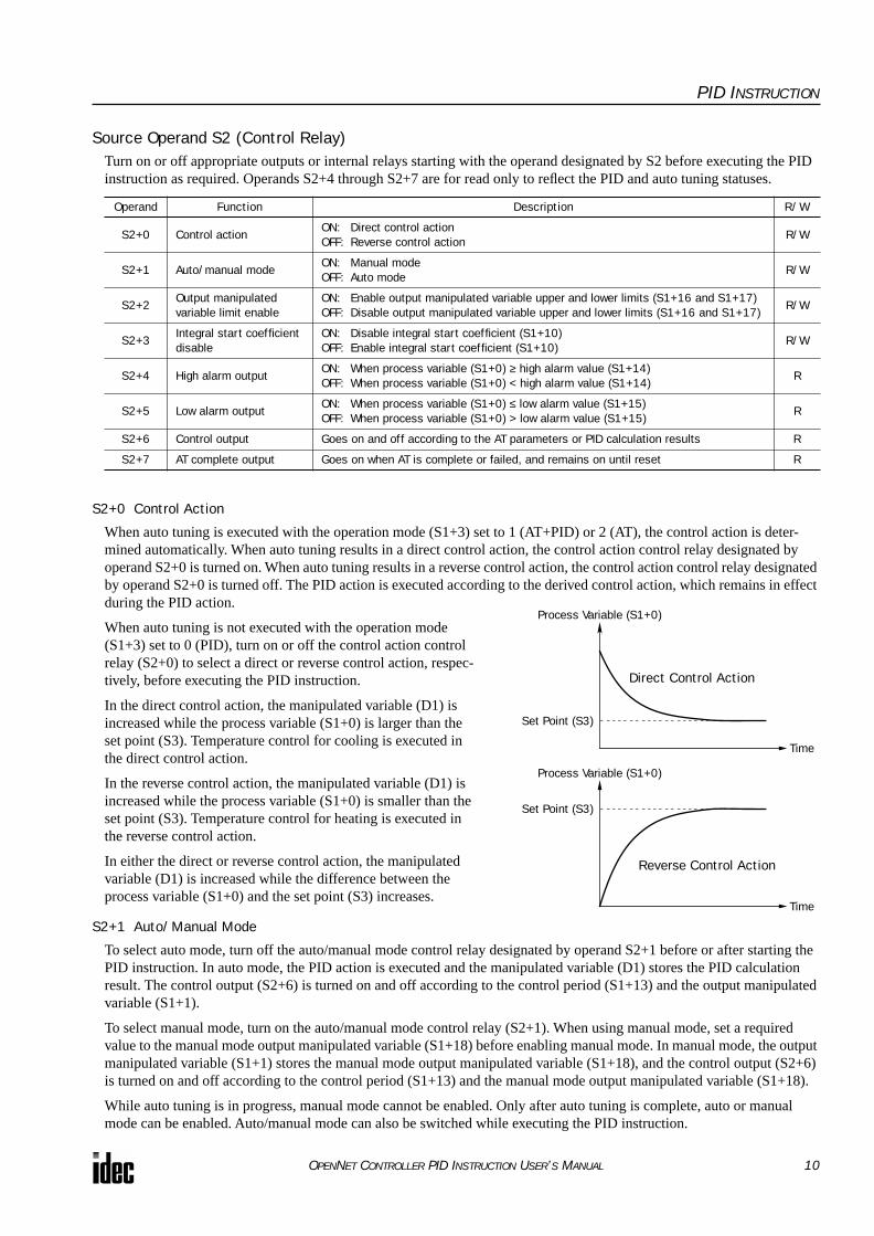
Source Operand S2 (Control Relay)Turn on or off appropriate outputs or internal relays starting with the operand designated by S2 before executing the PID instruction as required. Operands S2+4 through S2+7 are for read only to reflect the PID and auto tuning statuses.
S2+0 Control Action
When auto tuning is executed with the operation mode (S1+3) set to 1 (AT+PID) or 2 (AT), the control action is deter-mined automatically. When auto tuning results in a direct control action, the control action control relay designated by operand S2+0 is turned on. When auto tuning results in a reverse control action, the control action control relay designated by operand S2+0 is turned off. The PID action is executed according to the derived control action, which remains in effect during the PID action.
When auto tuning is not executed with the operation mode (S1+3) set to 0 (PID), turn on or off the control action control relay (S2+0) to select a direct or reverse control action, respec-tively, before executing the PID instruction.
In the direct control action, the manipulated variable (D1) is increased while the process variable (S1+0) is larger than the set point (S3). Temperature control for cooling is executed in the direct control action.
In the reverse control action, the manipulated variable (D1) is increased while the process variable (S1+0) is smaller than the set point (S3). Temperature control for heating is executed in the reverse control action.
In either the direct or reverse control action, the manipulated variable (D1) is increased while the difference between the process variable (S1+0) and the set point (S3) increases.
S2+1 Auto/Manual Mode
To select auto mode, turn off the auto/manual mode control relay designated by operand S2+1 before or after starting the PID instruction. In auto mode, the PID action is executed and the manipulated variable (D1) stores the PID calculation result. The control output (S2+6) is turned on and off according to the control period (S1+13) and the output manipulated variable (S1+1).
To select manual mode, turn on the auto/manual mode control relay (S2+1). When using manual mode, set a required value to the manual mode output manipulated variable (S1+18) before enabling manual mode. In manual mode, the output manipulated variable (S1+1) stores the manual mode output manipulated variable (S1+18), and the control output (S2+6) is turned on and off according to the control period (S1+13) and the manual mode output manipulated variable (S1+18).
While auto tuning is in progress, manual mode cannot be enabled. Only after auto tuning is complete, auto or manual mode can be enabled. Auto/manual mode can also be switched while executing the PID instruction.
Operand Function Description R/W
S2+0 Control actionON: Direct control actionOFF: Reverse control action
R/W
S2+1 Auto/manual modeON: Manual modeOFF: Auto mode
R/W
S2+2Output manipulated variable limit enable
ON: Enable output manipulated variable upper and lower limits (S1+16 and S1+17)OFF: Disable output manipulated variable upper and lower limits (S1+16 and S1+17)
R/W
S2+3Integral start coefficient disable
ON: Disable integral start coefficient (S1+10)OFF: Enable integral start coefficient (S1+10)
R/W
S2+4 High alarm outputON: When process variable (S1+0) ≥ high alarm value (S1+14)OFF: When process variable (S1+0) < high alarm value (S1+14)
R
S2+5 Low alarm outputON: When process variable (S1+0) ≤ low alarm value (S1+15)OFF: When process variable (S1+0) > low alarm value (S1+15)
R
S2+6 Control output Goes on and off according to the AT parameters or PID calculation results R
S2+7 AT complete output Goes on when AT is complete or failed, and remains on until reset R
Process Variable (S1+0)
Direct Control Action
Set Point (S3)
Time
Process Variable (S1+0)
Reverse Control Action
Set Point (S3)
Time
OPENNET CONTROLLER PID INSTRUCTION USER’S MANUAL 10
PID INSTRUCTION
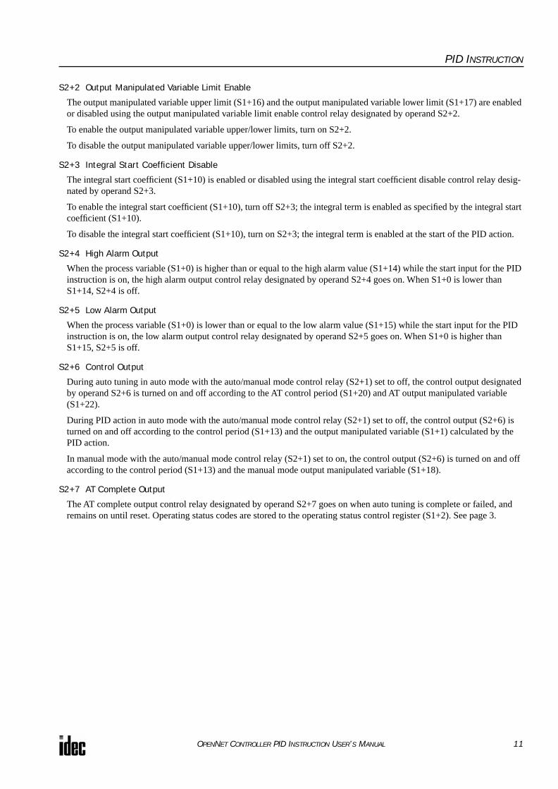
S2+2 Output Manipulated Variable Limit Enable
The output manipulated variable upper limit (S1+16) and the output manipulated variable lower limit (S1+17) are enabled or disabled using the output manipulated variable limit enable control relay designated by operand S2+2.
To enable the output manipulated variable upper/lower limits, turn on S2+2.
To disable the output manipulated variable upper/lower limits, turn off S2+2.
S2+3 Integral Start Coefficient Disable
The integral start coefficient (S1+10) is enabled or disabled using the integral start coefficient disable control relay desig-nated by operand S2+3.
To enable the integral start coefficient (S1+10), turn off S2+3; the integral term is enabled as specified by the integral start coefficient (S1+10).
To disable the integral start coefficient (S1+10), turn on S2+3; the integral term is enabled at the start of the PID action.
S2+4 High Alarm Output
When the process variable (S1+0) is higher than or equal to the high alarm value (S1+14) while the start input for the PID instruction is on, the high alarm output control relay designated by operand S2+4 goes on. When S1+0 is lower than S1+14, S2+4 is off.
S2+5 Low Alarm Output
When the process variable (S1+0) is lower than or equal to the low alarm value (S1+15) while the start input for the PID instruction is on, the low alarm output control relay designated by operand S2+5 goes on. When S1+0 is higher than S1+15, S2+5 is off.
S2+6 Control Output
During auto tuning in auto mode with the auto/manual mode control relay (S2+1) set to off, the control output designated by operand S2+6 is turned on and off according to the AT control period (S1+20) and AT output manipulated variable (S1+22).
During PID action in auto mode with the auto/manual mode control relay (S2+1) set to off, the control output (S2+6) is turned on and off according to the control period (S1+13) and the output manipulated variable (S1+1) calculated by the PID action.
In manual mode with the auto/manual mode control relay (S2+1) set to on, the control output (S2+6) is turned on and off according to the control period (S1+13) and the manual mode output manipulated variable (S1+18).
S2+7 AT Complete Output
The AT complete output control relay designated by operand S2+7 goes on when auto tuning is complete or failed, and remains on until reset. Operating status codes are stored to the operating status control register (S1+2). See page 3.
OPENNET CONTROLLER PID INSTRUCTION USER’S MANUAL 11
PID INSTRUCTION
Source Operand S3 (Set Point)The PID action is executed to adjust the process variable (S1+0) to the set point (S3).
When the linear conversion is disabled (S1+4 set to 0), set a required set point value of 0 through 4000 to the operand des-ignated by S3. Valid operands are data register and constant.
When the linear conversion is enabled (S1+4 set to 1), designate a data register as operand S3 and set a required set point value of –32768 through 32767 to the data register designated by operand S3. Since the PID instruction uses the word data type, negative constants cannot be entered directly to operand S3. Use the MOV instruction with the integer (I) data type to store a negative value to a data register. The set point value (S3) must be larger than or equal to the linear conversion min-imum value (S1+6) and smaller than or equal to the linear conversion maximum value (S1+5).
When an invalid value is designated as a set point, the PID action is stopped and an error code is stored to the data register designated by operand S1+2. See Operating Status on page 3.
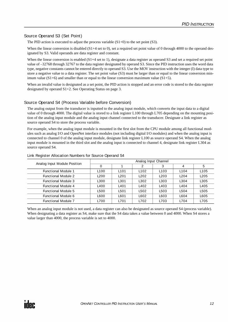
Source Operand S4 (Process Variable before Conversion)The analog output from the transducer is inputted to the analog input module, which converts the input data to a digital value of 0 through 4000. The digital value is stored to a link register L100 through L705 depending on the mounting posi-tion of the analog input module and the analog input channel connected to the transducer. Designate a link register as source operand S4 to store the process variable.
For example, when the analog input module is mounted in the first slot from the CPU module among all functional mod-ules such as analog I/O and OpenNet interface modules (not including digital I/O modules) and when the analog input is connected to channel 0 of the analog input module, designate link register L100 as source operand S4. When the analog input module is mounted in the third slot and the analog input is connected to channel 4, designate link register L304 as source operand S4.
Link Register Allocation Numbers for Source Operand S4
When an analog input module is not used, a data register can also be designated as source operand S4 (process variable). When designating a data register as S4, make sure that the S4 data takes a value between 0 and 4000. When S4 stores a value larger than 4000, the process variable is set to 4000.
Analog Input Module PositionAnalog Input Channel
0 1 2 3 4 5Functional Module 1 L100 L101 L102 L103 L104 L105Functional Module 2 L200 L201 L202 L203 L204 L205Functional Module 3 L300 L301 L302 L303 L304 L305Functional Module 4 L400 L401 L402 L403 L404 L405Functional Module 5 L500 L501 L502 L503 L504 L505Functional Module 6 L600 L601 L602 L603 L604 L605Functional Module 7 L700 L701 L702 L703 L704 L705
OPENNET CONTROLLER PID INSTRUCTION USER’S MANUAL 12

PID INSTRUCTION
Destination Operand D1 (Manipulated Variable)The data register designated by destination operand D1 stores the manipulated variable of –32768 through 32767 calcu-lated by the PID action. When the calculation result is less than –32768, D1 stores –32768. When the calculation result is greater than 32767, D1 stores 32767. While the calculation result is less than –32768 or greater than 32767, the PID action still continues.
When the output manipulated variable limit is disabled (S2+2 set to off) while the PID action is in progress, the data regis-ter designated by operand S1+1 holds 0 through 100 of the manipulated variable (D1), omitting values less than 0 and greater than 100. The percent value in S1+1 determines the ON duration of the control output (S2+6) in proportion to the control period (S1+13).
When the output manipulated variable limit is enabled (S2+2 set to on), the manipulated variable (D1) is stored to the out-put manipulated variable (S1+1) according to the output manipulated variable upper limit (S1+16) and the output manipu-lated variable lower limit (S1+17) as summarized in the table below.
While manual mode is enabled with the auto/manual mode control relay (S2+1) set to on, S1+1 stores 0 through 100 of the manual mode output manipulated variable (S1+18), and D1 stores an indefinite value.
While auto tuning is in progress, S1+1 stores 0 through 100 of the AT output manipulated variable (S1+22), and D1 stores an indefinite value.
Examples of Output Manipulated Variable Values
Output Manipulated Variable Limit Enable
(S2+2)
Output Manipulated Variable Upper Limit
(S1+16)
Output Manipulated Variable Lower Limit
(S1+17)
Manipulated Variable(D1)
Output Manipulated Variable(S1+1)
OFF (disabled) — —
≥ 100 100
1 to 99 1 to 99
≤ 0 0
ON (enabled)
50 25
≥ 50 50
26 to 49 26 to 49
≤ 25 25
10050 —
≥ 100 50
1 to 99 (1 to 99) × 0.5
≤ 0 0
OPENNET CONTROLLER PID INSTRUCTION USER’S MANUAL 13

PID INSTRUCTION
Application ExampleThis application example demonstrates a PID control for a heater to keep the temperature at 200°C.
In this example, when the program is started, the PID instruction first executes auto tuning according to the designated AT parameters, such as AT sampling period, AT control period, AT set point, and AT output manipulated variable, and also the temperature data inputted to the analog input module. The control output remains on to keep the heater on until the tem-perature reaches the AT set point of 150°C. Auto tuning determines PID parameters such as proportional gain, integral time, derivative time, and control action.
When the temperature reaches 150°C, PID action starts to control the temperature to 200°C using the derived PID param-eters. The heater is turned on and off according to the output manipulated variable calculated by the PID action. When the heater temperature is higher than or equal to 250°C, an alarm light is turned on by the high alarm output.
The analog input module data is also monitored to force off the heater power switch.
Operand Settings
Note: The output manipulated variable during auto tuning is a constant value. In this example, the AT output manipulated variable is set to the maximum value of 100 (100%), so the control output (S2+6) remains on during auto tuning.
Operand Function DescriptionAllocation No.
(Value)S1+3 Operation mode AT (auto tuning) + PID action D3 (1)S1+4 Linear conversion Enable linear conversion D4 (1)S1+5 Linear conversion maximum value 500°C D5 (5000)S1+6 Linear conversion minimum value –50°C D6 (–500)S1+10 Integral start coefficient 100% D10 (0)S1+11 Input filter coefficient 70% D11 (70)S1+12 Sampling period 500 msec D12 (50)S1+13 Control period 1 sec D13 (10)S1+14 High alarm value 250°C D14 (2500)S1+19 AT sampling period 1.5 sec D19 (150)S1+20 AT control period 3 sec D20 (30)S1+21 AT set point 150°C D21 (1500)S1+22 AT output manipulated variable 100% (Note) D22 (100)S2+1 Auto/manual mode Auto mode M1 (OFF)
S2+2Output manipulated variable limit enable
Disable output manipulated variable limits M2 (OFF)
S2+3 Integral start coefficient disable Enable integral start coefficient (S1+10) M3 (OFF)
S2+4 High alarm outputON: When temperature ≥ 250°COFF: When temperature < 250°C
M4
S2+6 Control output
Remains on during auto tuning; Goes on and off according to the control period (S1+13) and output manipulated variable (S1+1) during PID action
M6
S3 Set point 200°C D100 (2000)
S4 Process variable
Analog input module is mounted at the first slot among functional modules and the analog input is connected to channel 0 of the analog input module; stores 0 through 4000
L100
D1 Manipulated variable Stores PID calculation result (–32768 to 32767) D102PID start input Starts to execute the PID instruction I0
Monitor inputStarts to monitor the analog input module data for high alarm
I1
Heater power switch Turned on and off by control output M6 Q0High alarm light Turned on and off by high alarm output M4 Q1
OPENNET CONTROLLER PID INSTRUCTION USER’S MANUAL 14

PID INSTRUCTION
System Setup
Digital Output from Analog Input Module vs. Process Variable after Conversion
Temperature Control by Auto Tuning and PID Action
AB
GR
S485
CO
MA
BZ
HS
CO
UT
+24V
0V
POWER
RUN
ERROR
HSC OUT
1
2
3
4
5
6
7
8
9
10
11
12
13
14
15
16
17
18
19
20
A/D
+_24V DC
Fuse
CPU ModuleRelay Output Module
FC3A-R161Analog Input Module
FC3A-AD1261
012345671011121314151617
1
2
3
4
5
6
7
8
9
10
11
12
13
14
15
16
17
18
19
20
RyOUT
Transducer–50° to 500°C
Thermocouple
High Alarm LightOutput Q1
Output Q0 Heater Power Switch
L
Heater
High Alarm Value (S1+14): 2500 (250°C)
4000Linear Conversion Minimum Value (S1+6): –500 (–50°C)
0
Linear Conversion Maximum Value (S1+5): 5000 (500°C)
Set Point (S3): 2000 (200°C)AT Set Point (S1+21): 1500 (150°C)
Digital Output from Analog Input Module
Process Variable after Conversion (S1+0)
Process Variable after Conversion (S1+0)
Time
High Alarm Value (S1+14): 2500 (250°C)
Set Point (S3): 2000 (200°C)
AT Set Point (S1+21): 1500 (150°C)
Auto Tuning
PID Action
OPENNET CONTROLLER PID INSTRUCTION USER’S MANUAL 15

PID INSTRUCTION
Ladder ProgramThe ladder diagram shown below describes an example of using the PID instruction. The user program must be modified according to the application and simulation must be performed before actual operation.
When input I0 is turned on, 0 is stored to 27 data registers D0 through D26 designated as control registers.
D3 (operation mode): 1 (AT+PID)
D4 (linear conversion): 1 (enable linear conversion)
D5 (linear conversion maximum value): 5000 (500°C)
D6 (linear conversion minimum value): –500 (–50°C)
D10 (integral start coefficient): 0 (100%)
D11 (input filter coefficient): 70 (70%)
D12 (sampling period): 50 (500 msec)
D13 (control period): 10 (1 sec)
D14 (high alarm value): 2500 (250°C)
D19 (AT sampling period): 150 (1.5 sec)
D20 (AT control period): 30 (3 sec)
D21 (AT set point): 1500 (150°C)
D22 (AT output manipulated variable): 100 (100%)
D100 (set point): 2000 (200°C)
S1 –1
D1 –D3
MOV(W) REP
S1 –1
D1 –D4
MOV(W) REP
S1 –5000
D1 –D5
MOV(I) REP
S1 ––500
D1 –D6
MOV(I) REP
S1 –70
D1 –D11
MOV(W) REP
S1 –50
D1 –D12
MOV(W) REP
S1 –10
D1 –D13
MOV(W) REP
S1 –2500
D1 –D14
MOV(W) REP
S1 –150
D1 –D19
MOV(W) REP
S1 –30
D1 –D20
MOV(W) REP
S1 –1500
D1 –D21
MOV(W) REP
S1 –100
D1 –D22
MOV(W) REP
S1 –2000
D1 –D100
MOV(W) REP
M3R
M2R
M1R
When input I0 is turned on, 3 internal relays M1 through M3 designated as control relays are turned off.
M1 (auto/manual mode): Auto modeM2 (output manipulated variable limit enable): DisableM3 (integral start coefficient disable): Enable
While input I0 is on, the PID instruction is executed.
D0-D26: control registersM0-M7: control relaysD100: set pointL100: process variableD102: manipulated variable
When internal relay M6 (control output) is turned on, out-put Q0 (heater power switch) is turned on.
When internal relay M4 (high alarm output) is turned on, output Q1 (high alarm light) is turned on.
S1 –0
D1 RD0
MOV(W) REP27
S1 –0
D1 –D10
MOV(W) REP
I0SOTU
I0D1
D102S1D0
S2M0
S3D100
PID S4L100
M6
M4
Q0
Q1
M4
Continued on the next page.
OPENNET CONTROLLER PID INSTRUCTION USER’S MANUAL 16

PID INSTRUCTION
Ladder Program (continued)
Notes for Using the PID Instruction:• Since the PID instruction requires continuous operation, keep on the start input for the PID instruction.
• The high alarm output (S2+4) and the low alarm output (S2+5) work while the start input for the PID instruction is on. These alarm outputs, however, do not work when a PID instruction execution error occurs (S1+2 stores 100 through 107) due to data error in control data registers S1+0 through S1+26 or while the start input for the PID instruction is off. Pro-vide a program to monitor the process variable (S4) separately.
• When a PID execution error occurs (S1+2 stores 100 through 107) or when auto tuning is completed, the manipulated variable (D1) stores 0 and the control output (S2+6) turns off.
• Do not use the PID instruction in program branching instructions: LABEL, LJMP, LCAL, LRET, JMP, JEND, MCS, and MCR. The PID instruction may not operate correctly in these instructions.
• The PID instruction, using the difference between the set point (S3) and process variable (S4) as input, calculates the manipulated variable (D1) according to the PID parameters, such as proportional gain (S1+7), integral time (S1+8), and derivative time (S1+9). When the set point (S3) or process variable (S4) is changed due to disturbance, overshoot or undershoot will be caused. Before putting the PID control into actual application, perform simulation tests by changing the set point and process variable (disturbance) to anticipated values in the application.
• The PID parameters, such as proportional gain (S1+7), integral time (S1+8), and derivative time (S1+9), determined by the auto tuning may not always be the optimum values depending on the actual application. To make sure of the best results, adjust the parameters. Once the best PID parameters are determined, perform only the PID action in usual opera-tion unless the control object is changed.
• When a feedback control is executed using the control output (S2+6), the optimum control may not be achieved depend-ing on the controlled object. If this is the case, use of the manipulated variable (D1) in the feedback control is recom-mended.
Q0R
While monitor input I1 is on, the temperature is monitored.When the temperature is higher than or equal to 250°C, M10 is turned on.
4000 × 250/1300 = 769.23
When M10 is on while monitor input I1 is on, Q0 (heater power switch) is forced off and Q1 (high alarm light) is forced on.
I1REPS1 –
L100D1 –M10
CMP>=(W) S2 –769
M10 I1
Q1S
OPENNET CONTROLLER PID INSTRUCTION USER’S MANUAL 17