A Dynamic Model of Hydrostatic Reactor Coolant …glc.ans.org/nureth-16/data/papers/13375.pdfa...
14
A Dynamic Model of Hydrostatic Mechanical Face Seals for RELAP5/MOD3.3 Michael LaPresti Westinghouse Electric Company LLC Technology and Innovation 1320 Beulah Road, Pittsburgh, PA 15235, USA [email protected] Naugab E. Lee, Ruben J. Espinosa, Michael Volodzko, and Mie Azuma Westinghouse Electric Company LLC Transient and LOCA Analysis 20 International Drive, Windsor, CT 06095, USA [email protected], [email protected], [email protected], [email protected] ABSTRACT Commercial pressurized water reactors often employ hydrostatic mechanical face seals between the motor and hydraulic sections of the reactor coolant pumps. Such seals are designed to permit controlled leakage while experiencing minimal wear by maintaining constant separation by a thin fluid film between the seal faces. Leakage through the seal is dependent upon the face geometry and mechanical design as well as the thermodynamic state of the sealed fluid. During normal modes of operation, seal leakage is compensated by makeup from the chemical and volume control system; however, failures of the seals or supporting systems can lead to significant inventory loss from the reactor. A fluid-structure interaction model is developed to predict seal performance and simulate the response to system perturbations. Integration of the fluid-structure interaction model into the RELAP5/MOD3.3 thermal-hydraulic safety analysis code allows for coupled simulations of the seal and supporting fluid systems under transient or steady state operation. Best estimate predictions of seal leakage are obtained for normal operating and faulted conditions. KEYWORDS Hydrostatic seals, transient, simulation 5756 NURETH-16, Chicago, IL, August 30-September 4, 2015
Transcript of A Dynamic Model of Hydrostatic Reactor Coolant …glc.ans.org/nureth-16/data/papers/13375.pdfa...

A Dynamic Model of Hydrostatic Mechanical Face Seals for RELAP5/MOD3.3
Michael LaPresti
Westinghouse Electric Company LLC Technology and Innovation
1320 Beulah Road, Pittsburgh, PA 15235, USA
Naugab E. Lee, Ruben J. Espinosa, Michael Volodzko, and Mie Azuma
Westinghouse Electric Company LLC Transient and LOCA Analysis
20 International Drive, Windsor, CT 06095, USA
[email protected], [email protected], [email protected], [email protected]
ABSTRACT Commercial pressurized water reactors often employ hydrostatic mechanical face seals between the motor and hydraulic sections of the reactor coolant pumps. Such seals are designed to permit controlled leakage while experiencing minimal wear by maintaining constant separation by a thin fluid film between the seal faces. Leakage through the seal is dependent upon the face geometry and mechanical design as well as the thermodynamic state of the sealed fluid. During normal modes of operation, seal leakage is compensated by makeup from the chemical and volume control system; however, failures of the seals or supporting systems can lead to significant inventory loss from the reactor. A fluid-structure interaction model is developed to predict seal performance and simulate the response to system perturbations. Integration of the fluid-structure interaction model into the RELAP5/MOD3.3 thermal-hydraulic safety analysis code allows for coupled simulations of the seal and supporting fluid systems under transient or steady state operation. Best estimate predictions of seal leakage are obtained for normal operating and faulted conditions.
KEYWORDS
Hydrostatic seals, transient, simulation
5756NURETH-16, Chicago, IL, August 30-September 4, 2015 5756NURETH-16, Chicago, IL, August 30-September 4, 2015

1. BACKGROUND AND HISTORICAL PERSPECTIVE Light water nuclear reactors throughout the world typically consist of a nuclear core, turbine generator, and suitable pumping capacity for circulating coolant within the system in order to generate power by the Rankine cycle. Such reactor designs can be arranged in a single closed-loop configuration, as commonly used in boiling water reactors, or a dual loop configuration in which the reactor coolant is maintained as a subcooled liquid and heat is transferred to a secondary steam system utilizing heat exchangers. Pumps employed in these systems demand high reliability and safety margin, as their performance is required for economical power generation as well as safe operation of the plant. For pressurized water reactors, the primary system typically consists of a reactor vessel containing the nuclear core, a steam generator for transferring heat to the secondary loop, reactor coolant pumps, and a pressurizer. The primary system is often configured with two, three, or four loops passing through the reactor, each of which has a pump and steam generator. The thermodynamic conditions in the primary system are balanced between the need to maintain safe conditions for the pressure boundary and fuel and the ability to economically generate power. Shaft-seal style pumps are the chosen technology for application in Westinghouse pressurized water reactors, with similar arrangements being selected for other manufacturers’ nuclear steam supply systems. The need for high reliability combined with the severe thermodynamic conditions, relatively large shaft size, radiation and chemical environment, and shaft speed poses a challenging sealing problem, and considerable effort was expended upon developing the technology that is the basis for pump seals currently in use today. To satisfy these requirements, a hydrostatic film-riding seal was developed which was capable of limiting leakage to acceptably low values while maintaining an adequate film thickness to avoid face contact and wear. In addition to its primary sealing function, the reactor coolant pump seal system serves a number of other critical functions, including allowing for cooling flow through the pump bearing and providing a pathway for chemical additions to the reactor coolant system. The Westinghouse reactor coolant pump seal design consists of three stages, one high pressure film-riding seal and two subsequent stages of the face-rubbing type. The first stage utilizes ceramic seal faces and experiences 99% of the total pressure drop, while the second and third stages use a graphite on stainless interface, each experiencing a small pressure drop and allowing minimal leakage. While reactor coolant in the hydraulic section of the pump is maintained at approximately 15.5 MPa and 288°C, a buffer of cool injection water is maintained at the seal inlet to limit its temperature to nominally 65°C. This prevents flashing across the faces and inhibits deleterious effects such as flow erosion, corrosion, the ingress of foreign material, or chemical attack. A redundant system is provided to maintain seal cooling in the event that the injection system becomes inoperable; however both cooling systems require the availability of AC power. 1.1. Seal Modeling Applications Reactor coolant pump seal performance, as characterized by the parameters of leakage rate and temperature, is closely monitored by plant operators as these values must remain within a relatively narrow range in order for safe pump operation to be maintained. Excessively low or
5757NURETH-16, Chicago, IL, August 30-September 4, 2015 5757NURETH-16, Chicago, IL, August 30-September 4, 2015

high leakage necessitates a plant shutdown for the seals to be serviced, resulting in potentially significant costs and lost power generation. In practice, seal leakage is observed to be affected by a wide range of plant parameters reaching as far as the ultimate heat sink temperature, and plant operators expend considerable effort to determine the particular cause of any observed perturbation in seal performance. Additionally, plant transients or accident scenarios, particularly those involving a loss of cooling to the seals, may result in elevated leakage rates and significant inventory loss from the reactor, which makes the seal performance under such circumstances an important boundary condition for safety analysis and the design of backup equipment. For these reasons, a robust analytical model of the reactor coolant pump seals is a valuable tool which can provide insight into seal behavior beyond the few indications available in plant service or experimental tests. In principle, a comprehensive model could be used in a confirmatory capacity by testing the hypothesized cause of a particular seal perturbation. The conclusions of such an evaluation can provide valuable information to plant managers, allowing for normal behaviors to be discriminated from problematic ones, affording a more judicious decision about when and how to perform seal maintenance than could otherwise be made using plant data alone. A predictive analysis is also valuable, such as that which could be performed to estimate the seal behavior during an accident scenario, providing critical inputs for designing safety equipment and developing operator response procedures. 1.2. Seal Modeling Landscape The value of analytical models for the reactor coolant pump seals has been recognized for nearly four decades. Advancement of digital computers and the refinement of numerical analysis techniques such as the finite element method allowed equipment manufacturers to develop the first simulation models of the reactor coolant pump seals in the 1970s. These early analyses generally consisted of a basic structural model of the seal hardware coupled with a one dimensional fluid dynamic calculation, together which provided estimates of the component deformation and seal leakage rates. Concerns regarding the seal performance during a loss of AC power event triggered a significant industry-wide development effort in the 1980s which included a number of advancements, notably the prediction of seal leakage rates at elevated temperatures and under two-phase flashing flow conditions [1,2]. Significant research and development efforts undertaken by Électricité de France (EdF) in the early 2000s led to a sophisticated modeling framework including thermo-elastic deformation, inertia within the fluid film, dynamic seal friction, and refined turbulence models. These studies were generally limited to steady state analyses, applicable in cases where the seal inlet and exit conditions were known and did not evolve over time. Models for studying the transient behavior of seals have received less consideration, with only a few examples being identified in the literature. Tournerie, Brunetière, and Danos proposed a two-dimensional transient model that was applied to characterize the thermo-elastic distortions and the resulting leakage behavior during a startup transient [6]. This model utilized the influence coefficient method similar to [4] for calculating the thermo-elastic deformations; however the model also incorporated a transient fluid energy equation and heat conduction model to supply the temperature gradients required for that calculation. Blasbalg and Salant proposed a similar model in [7] that also included a differential equation of motion describing the seal displacement, modeling of the asperity contact at the seal interface, and fluid dynamic
5758NURETH-16, Chicago, IL, August 30-September 4, 2015 5758NURETH-16, Chicago, IL, August 30-September 4, 2015
model suitable for two-phase flashing flow. The model in [7] was applied for evaluating the stability of a basic seal to perturbations in the equilibrium film thickness. These models outline a basic approach for studying the complex interdependences that govern the seal response to time varying conditions; however, it is unknown if they are suitable for efficient simulation of system-level transients common in nuclear plant operation.
This paper proposes a fully transient fluid-structure interaction model of hydrostatic mechanical face seals based on the nuclear safety analysis code RELAP5/MOD3.3. The model offers an efficient tool for simulating long duration transients, while providing suitable modeling of the complex thermo-elasto-hydrodynamic phenomena that govern the seal behavior. Furthermore, the existing features within RELAP5 allow for the study of fluid system and control system processes and their interactive effect on the seal behavior. A description of the basic approach as well as reference simulations for normal pump operation and a loss of seal injection transient are provided.
2. MODEL DESCRIPTION
2.1. Reactor Coolant Pump Seal System Operation
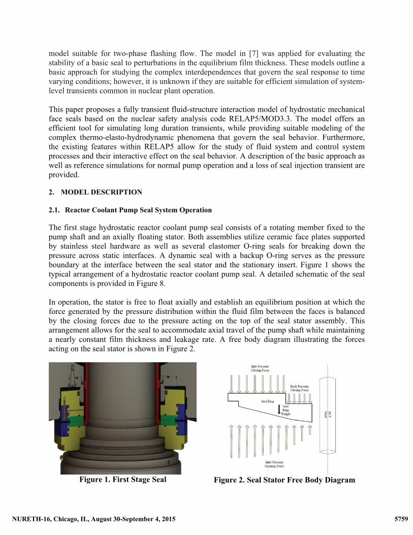
The first stage hydrostatic reactor coolant pump seal consists of a rotating member fixed to the pump shaft and an axially floating stator. Both assemblies utilize ceramic face plates supported by stainless steel hardware as well as several elastomer O-ring seals for breaking down the pressure across static interfaces. A dynamic seal with a backup O-ring serves as the pressure boundary at the interface between the seal stator and the stationary insert. Figure 1 shows the typical arrangement of a hydrostatic reactor coolant pump seal. A detailed schematic of the seal components is provided in Figure 8.
In operation, the stator is free to float axially and establish an equilibrium position at which the force generated by the pressure distribution within the fluid film between the faces is balanced by the closing forces due to the pressure acting on the top of the seal stator assembly. This arrangement allows for the seal to accommodate axial travel of the pump shaft while maintaining a nearly constant film thickness and leakage rate. A free body diagram illustrating the forces acting on the seal stator is shown in Figure 2.
Figure 1. First Stage Seal
Figure 2. Seal Stator Free Body Diagram
5759NURETH-16, Chicago, IL, August 30-September 4, 2015 5759NURETH-16, Chicago, IL, August 30-September 4, 2015

In addition to the axial motion of the seal stator, both seal faces experience small but significant deformations due to the mechanical and thermal-hydraulic loads acting upon them during operation. These loads are caused by effects such as non-uniform distributions of hydrostatic pressures, steady state and transient temperature gradients, preloads from elastomers and screws/fasteners, and contact loads at the interfaces between components. Such loads influence the shape of the fluid film and generally cause a change in the angle between the stationary and rotating faces of the seal, affecting the leakage and temperature rise. Within the pump, the seal package isolates the primary reactor coolant system from the containment atmosphere and is situated near the top of the pump assembly, as shown in Figure 3. In normal operation, a buffer of cool water is injected between the seals and pump impeller. The majority of leakage passing through the first stage seal exits the pump via a dedicated return line, with negligible flow traveling upward through the second and third stages. An independent system provides cooling water to an integral heat exchanger located below the pump bearing serving as a backup for maintaining seal cooling in the event that injection is lost. The pump casing, seal housing, thermal barrier, and shaft are constructed from various types of stainless steel, each having substantial heat capacity and surface area that may influence the thermal response of the pump during steady state or transient operation.
2.2. Modeling Considerations
From a modeling standpoint, the significance of the seal face deformation and the axial translation of the seal stator introduces strong interdependences that add considerable complexity to the analysis.
Figure 3. Reactor Coolant Pump
In the simplest explanation, the water temperature causes a thermal deformation of the seal faces, which alters the shape of the pressure distribution affecting the force balance and equilibrium axial position of the seal stator. The axial position of the seal stator affects the film pressure distribution, altering the mechanical deformation of the faces, which again affects the leakage rate and water temperature, and so on. Any model seeking to predict the behavior of the seal must account for these interactions and how they evolve over time. This is achieved within RELAP5 by utilizing the code’s existing fluid dynamic models, but incorporating suitable coding to calculate the seal face displacements and subsequently enforce the resulting impacts on the geometry of the fluid domain.
Within RELAP5, the domain for the fluid film between the faces is modeled with specially-modified “pipe” components, with dynamic geometry for representing axial translation of the seal stator and distortions due to the thermal and mechanical loadings. These “dynamic cells” are
Seal Package
Bearing
Thermal Barrier (Coils not shown)
Impeller
5760NURETH-16, Chicago, IL, August 30-September 4, 2015 5760NURETH-16, Chicago, IL, August 30-September 4, 2015

then connected to suitable boundary conditions, systems, and heat structures for modeling the particular seal behavior of interest. 2.3. Structural Mechanics Model The structural behavior of the seal faces that serves to alter the geometry of the fluid film is generally dominated by (1) axial translation of the seal stator ring, (2) pressure-induced deformation of the seal faces, and (3) thermal distortion of the seal faces. For the model proposed herein, these contributors are individually calculated and then combined to obtain the net deformed geometry based on the principle of superposition. Considering the seal stator axial translation, a simple equation of motion can be obtained by applying Newton’s second law to the seal ring [7].
������� =�� (1)
Where, m is the mass of the seal ring, h is minimum film thickness, t is time, and Fy consists of the opening and closing hydraulic forces as well as weight, spring forces, and friction. The first stage reactor coolant pump seal has a large film stiffness and small mass, and thus the natural frequency associated with its travel in the axial direction is large (>1000 Hz) compared to relatively slow thermal-hydraulic transients. For that reason, it can be assumed that the stator axial translation is quasi-steady, such that:
�� = ��� � � + ����� � + ����� � + ������� +������ = 0 (2) This assumption considerably reduces the computational cost of the resulting fluid-structure interaction system by avoiding the need to use exceedingly small time step sizes below the CFL condition. For the system level transients that this model is designed to study, the dynamic effects associated with seal ring translation are negligible1; however this simplification may require revisiting for application of the model to rapid transients (e.g. shock waves). The opening and closing hydraulic forces acting on the seal assembly are calculated by Equations (3) and (4) based on the thermal hydraulic conditions throughout the seal model at the end of a time step. ����� � = ���� � ����( � ���) + ����� � ����( !����) (3)
��� � � = 2�" # (#)�#$%$&
(4)
Where, Pinlet and Poutlet are the pressures upstream and downstream of the seal, P is the pressure field of the fluid film, r is the radial coordinate, and Ro, Rb, and Ri are the outside, balance, and inside radii of the seal, respectively. The axial spring force, friction, and weight of the seal can be added into the force balance as needed, depending on considerations specific to the type of
1 Blasbalg and Salant [7] made a similar approximation for transients dominated by slow dynamics.
5761NURETH-16, Chicago, IL, August 30-September 4, 2015 5761NURETH-16, Chicago, IL, August 30-September 4, 2015
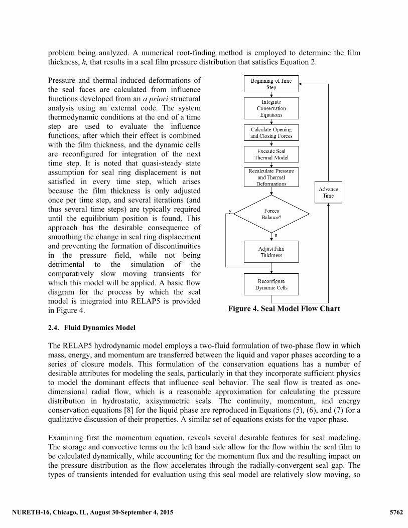
problem being analyzed. A numerical root-finding method is employed to determine the film thickness, h, that results in a seal film pressure distribution that satisfies Equation 2. Pressure and thermal-induced deformations of the seal faces are calculated from influence functions developed from an a priori structural analysis using an external code. The system thermodynamic conditions at the end of a time step are used to evaluate the influence functions, after which their effect is combined with the film thickness, and the dynamic cells are reconfigured for integration of the next time step. It is noted that quasi-steady state assumption for seal ring displacement is not satisfied in every time step, which arises because the film thickness is only adjusted once per time step, and several iterations (and thus several time steps) are typically required until the equilibrium position is found. This approach has the desirable consequence of smoothing the change in seal ring displacement and preventing the formation of discontinuities in the pressure field, while not being detrimental to the simulation of the comparatively slow moving transients for which this model will be applied. A basic flow diagram for the process by which the seal model is integrated into RELAP5 is provided in Figure 4.
Figure 4. Seal Model Flow Chart
2.4. Fluid Dynamics Model
The RELAP5 hydrodynamic model employs a two-fluid formulation of two-phase flow in which mass, energy, and momentum are transferred between the liquid and vapor phases according to a series of closure models. This formulation of the conservation equations has a number of desirable attributes for modeling the seals, particularly in that they incorporate sufficient physics to model the dominant effects that influence seal behavior. The seal flow is treated as one-dimensional radial flow, which is a reasonable approximation for calculating the pressure distribution in hydrostatic, axisymmetric seals. The continuity, momentum, and energy conservation equations [8] for the liquid phase are reproduced in Equations (5), (6), and (7) for a qualitative discussion of their properties. A similar set of equations exists for the vapor phase. Examining first the momentum equation, reveals several desirable features for seal modeling. The storage and convective terms on the left hand side allow for the flow within the seal film to be calculated dynamically, while accounting for the momentum flux and the resulting impact on the pressure distribution as the flow accelerates through the radially-convergent seal gap. The types of transients intended for evaluation using this seal model are relatively slow moving, so
5762NURETH-16, Chicago, IL, August 30-September 4, 2015 5762NURETH-16, Chicago, IL, August 30-September 4, 2015

the importance of a fully-dynamic momentum equation, compared to a quasi-steady state equation, is expected to be minor. However, as was shown by Galenne and Pierre-Danos in [5], simulating the inertial effects by inclusion of the convective term is expected to be significant. Wall friction losses are accounted for by the third term on the right hand side, which is useful for studying the surface roughness of the seal faces. The remaining terms on the right hand side account for various forms of momentum transfer between the liquid and vapor phases, and would become significant under two phase conditions, such as might arise during an accident scenario. When evaluating the continuity equation, it is worth noting that the proposed dynamic cells cause the seal film region to store both mass and energy, allowing for the film region to be non-equilibrium and non-isothermal. This is in contrast to early models, which only consider the seal as a momentum sink between upstream and downstream boundary conditions. The energy equation again includes a storage and flux term on the left hand side, with the pressure derivative, work, various sinks and sources, and interfacial energy transfer terms on the right hand side. Inclusion of the wall heat transfer and interphase heat transfer terms would be advantageous during a rapid temperature excursion in which the initially cool seal faces might remove heat from the fluid film and prevent or limit the presence of flashing between the faces, while the dissipative term offers a more precise calculation of the temperature distribution through the seal and the resulting effect on the thermo-elastic deformation.
''� �*�,�� +
1-''. �*�,�/�-� = 3� (5)
*�,�- '/�'� +12*�,�-
'/��'.= �*�- ' '. + *�,�45- � �*�,�-����(/6) � �*�,�-��7��/� � /��� 3�-�/�8 � /�� � 9*�*�,:- ;'(/� � /�)'� + /� '/�'. � /� '/�'. <
(6)
''� �*�,�>�� +
1-''. �*�,�>�/�-�
= � '*�'� � -''. �,�/�-� + ?@� + ?�� � 3����A � 3@��B + C7DD�
(7)
It is seen that the fluid dynamic model within RELAP5 provides a suitable theoretical framework for modeling the reactor coolant pump seals; however, the ultimate assessment is a pragmatic one: good agreement with observed seal performance and replication of the basic physics are used as the standard for applicability. 3. SIMULATIONS A basic model was developed to demonstrate the capability of the seal code and generate sample results. Two test cases were performed, one representing a plant pressurization transient and the second simulating a loss of seal injection with thermal barrier cooling maintained. Both cases
5763NURETH-16, Chicago, IL, August 30-September 4, 2015 5763NURETH-16, Chicago, IL, August 30-September 4, 2015

utilize a base RELAP5 input deck that includes control volumes for the water cavities inside the reactor coolant pump, heat structures representing the major metal components, the newly-designed “dynamic cells” for modeling the seal region, and pipe components representing the leak off system. Only the first stage seal is modeled, as the second and third stages would experience very little leakage for the cases considered. A sample nodalization diagram illustrating how the RELAP5 model was constructed is provided in Figure 5.
Figure 5. RELAP5 Nodalization of Reactor Coolant Pump, Seal, and Leak off System
3.1. Case 1: Pressurization Transient For the first case, upstream of the seal is initialized at 54.4°C and 1.38 MPa and the downstream boundary condition is set to 0.2 MPa. This is representative of the seal inlet conditions when the reactor coolant pump motor is started. A steady state run is performed to stabilize the initial pressure distribution throughout the seal and system, after which a restart run is executed to simulate the pressure transient. For this test case, the pressure is ramped linearly from 1.38 MPa to 15.5 MPa in 100 seconds. Note that this is much faster than a plant would be pressurized; however, dynamic effects are essentially negligible so the rapid pressurization was analyzed to reduce the execution time of the model. Two runs of this case are performed, the first with momentum flux enabled in the seal region and the second with it disabled. This is done to characterize the effect of inertia within the fluid film by quantifying its impact on the resulting leakage rate calculations, as was previously evaluated by Galenne and Pierre-Danos [5]. Plotting the volumetric leakage versus seal differential pressure for the first run produces a curve of the expected shape, where the leak rate increases in proportion to the differential pressure at a continuously decreasing rate. This curve is similar to the theoretical results and plant data
5764NURETH-16, Chicago, IL, August 30-September 4, 2015 5764NURETH-16, Chicago, IL, August 30-September 4, 2015

presented by Galenne and Pierre-Danos [5]. The leak rate stabilizes at approximately 600 l/h, which is consistent with the observed seal performance in the field and during tests. The second run was performed using identical conditions as the first, except that the momentum flux was disabled within all junctions by manipulating the jefhcahs flags within the RELAP5 input deck. Comparing the second run to the first (Figure 6) shows a calculated leak rate at 54.4°C and 15.5 MPa that is approximately 14% higher than that calculated with the momentum flux option enabled. This is consistent with the results obtained in [5] showing a significant reduction in the calculated leakage when inertial effects were accounted for in the fluid dynamic calculations.
Additional performance characteristics calculated by the model are provided in Table 1. For the given leakage rate, the leak off temperature and thermal barrier performance is consistent with test and field experience. The secondary cooling system providing flow to the thermal barrier heat exchanger is calculated to remove 49 kW of heat, which is mostly due to heat conduction from the reactor coolant system through the pump internals and into the thermal barrier. With the calculations performed in the static condition (no shaft rotation), the seal leak off temperature is calculated to be 57.9°C, indicating a temperature rise of 3.5°C across the seal. In the dynamic (shaft rotating) condition, additional heat generation due to friction and windage in the reactor coolant pump and seal internals would generally increase the temperature rise by approximately 5-10°C. Nevertheless, these
Figure 6. Case 1 - Leakage vs. Pressure during Plant Pressurization
Table 1. Calculated Parameters (Case 1)
Reactor Coolant System Primary Temperature °C 291.7 Primary Pressure MPa 15.5
Injection System Injection Pressure MPa 15.5 Injection Temperature °C 54.4 Injection Flow l/h 1810
Seal System Pump Running No No. 1 Seal Leak off Temp °C 57.9 No. 1 Seal Leak off Flow l/h 591 No. 1 Seal Leak off Pressure MPa 0.21
Thermal Barrier Inlet Temperature °C 40.6 Outlet Temperature °C 45.2 Flow l/h 9083 Heat Removal kW 49
results indicate that the seal model is predicting prototypical performance and interacting in the expected ways with the supporting systems and components.
3.2. Case 2: Loss of Seal Injection Transient
A second case is performed to simulate the pump and seal response to a loss of seal injection flow, a typical design transient for the reactor coolant pump. Under normal operation, the seals are provided with two independent cooling sources: seal injection and thermal barrier cooling.
5765NURETH-16, Chicago, IL, August 30-September 4, 2015 5765NURETH-16, Chicago, IL, August 30-September 4, 2015
The seal injection flow is generally around 1800 l/h, a portion of which travels upward and through the seal while the remainder travels downward through the thermal barrier and into the pump casing. In this mode of operation, the pump bearing and upper internals are cooled by the seal injection flow and the thermal barrier heat exchanger operates at a very low duty, as shown in the Case 1 calculation. If seal injection flow is terminated, the flow through the upper pump internals reverses and begins to leak upward from the pump casing through the thermal barrier and into the seals. In this mode of operation, leakage from the reactor coolant system must be cooled to an acceptably low temperature (typically < 112°C) by the thermal barrier heat exchanger to avoid damage to the lower radial bearing and seals. Seal leakage flow and temperature must also remain within acceptable levels for safe operation of the pump to continue. This transient is simulated using the same model as case 1. First, the model is initialized at normal operating temperature and pressure of 291.7°C and 15.5 MPa, respectively, with seal injection flow of 1810 l/h at 54.4°C. The steady state leakage rate calculated at these conditions is 594 l/h. After an initial period at steady state, the time dependent junction controlling seal injection flow is reduced to 0 l/h over a period of ten seconds. After losing seal injection, the faulted condition is assumed to persist for 15 minutes after which the system is recovered and seal injection is restarted at a rate of 1810 l/h. Key results from the loss of seal injection simulation are provided in Figure 7. The seal leak off temperature is observed to begin increasing almost immediately after seal injection flow is terminated and steadily rises from the initial temperature of approximately 58°C to approximately 75°C before injection flow is restored. The volumetric leakage initially experiences a slight decrease due to a slug of cold water passing upward from the thermal barrier into the seals during the flow reversal, after which it increases from the initial leak rate of 594 l/h to over 800 l/h before again decreasing. At 15 minutes when seal injection is restarted, the leakage rate shows a perturbation before rapidly decreasing, ultimately stabilizing near the pre-event leakage rate. The thermal barrier performance during the transient is characterized by the bottom plots in Figure 7. The initial primary flow is shown as approximately -1200 l/h, which consists of the excess seal injection traveling downward into the pump casing. After seal injection is lost, the flow reverses as leakage begins to travel upward from the pump casing through the shell side of the thermal barrier heat exchanger and into the seals. In the absence of seal injection, leakage from the reactor coolant system at 291.7°C enters the shell side of the heat exchanger, which significantly increases the heat transfer in the thermal barrier heat exchanger, immediately driving up the exit temperature of secondary cooling water from the initial value of approximately 45°C to nearly 65°C. The peak duty reaches approximately 250 kW before seal injection is restored. The maximum leakage rate, leak off temperature, and pump bearing temperature remained within normal limits during the entire transient, indicating acceptable performance during the loss of seal injection event.
5766NURETH-16, Chicago, IL, August 30-September 4, 2015 5766NURETH-16, Chicago, IL, August 30-September 4, 2015

Figure 7. Time Histories from Loss of Seal Injection Transient
4. CONCLUSIONS
A dynamic fluid-structure interaction model of hydrostatic mechanical face seals is developed and integrated into RELAP5/MOD3.3. The resulting model allows for realistic transient simulations of reactor coolant pump seal performance in a wide range of operating scenarios such as normal operation, plant transients, and accidents. Two case studies are presented that show reasonable agreement with similar analytical models and field experience.
Future work on the model should focus on computational efficiency improvements that would allow the simulations to be performed on finer grids, over longer periods of time, and with greater stability. In the current model, the large number of small cells in the seal film region limits the material Courant limit and requires very small time steps. A coupling scheme that would allow the seal region and adjoining system components to be integrated at different time step sizes could yield a vast improvement in computational efficiency. Additional improvement to the thermo-elastic deformation model, perhaps extending this function into a three-dimensional form could improve the generality of the code and allow for more precise modeling of small perturbations in the system.
5767NURETH-16, Chicago, IL, August 30-September 4, 2015 5767NURETH-16, Chicago, IL, August 30-September 4, 2015

NOMENCLATURE
-: Flow Area ��:Seal Inside Radius 4: Body Force �:Seal Outside Radius CFL: Courant-Friedrichs-Lewy condition �:Time C7DD: Energy dissipation function >: Specific internal energy F: Force /: Velocity �7�: Interfacial drag coefficient .: Radial length coordinate���: Wall drag coefficient *: Void Fraction �: Seal film thickness or specific enthalpy 3: Mass transfer rate �:Mass ,: Density : Pressure Subscript f: liquid phase ?:Volumetric heat addition rate Subscript g: vapor phase #:Radial coordinate Subscript i: liquid/vapor interface ��:Seal Balance Radius Subscript x: radial direction
Figure 8. Reactor Coolant Pump Hydrostatic Seal Components
Fluid Film
Balance Radius
5768NURETH-16, Chicago, IL, August 30-September 4, 2015 5768NURETH-16, Chicago, IL, August 30-September 4, 2015

ACKNOWLEDGMENTS The authors wish to thank Terry Gancarz for assistance in developing the thermal barrier heat exchanger model, Cory Stansbury for help with the graphics throughout, and Michael Skocik and Westinghouse AFS for supporting the development of this work. REFERENCES (1) Boardman, T., Jeanmougin, N., Lofaro, R., and Prevost, J., “Leak Rate Analysis of the
Westinghouse Reactor Coolant Pump Seal,” U.S. Nuclear Regulatory Commission Report NUREG/CR-4294, (1985).
(2) Rhodes, D.B., Hill, R.C., and Wensel, R.G., “Reactor Coolant Shaft Seal Stability during
Station Blackout,” U.S. Nuclear Regulatory Commission Report NUREG/CR-4821, (1987).
(3) Tournerie, B., Danos, J.C., and Frêne, J., “Three-Dimensional Modeling of THD Lubrication in Face-Seals,” Journal of Tribology, 123(1), pp. 196-204 (2001).
(4) Brunetière, N., Tournerie, B., Frêne, J., “TEHD Lubrication of Mechanical Face Seals in Stable Tracking Mode: Part 1—Numerical Model and Experiments,” Journal of Tribology, 125(3), pp. 608-616 (2003).
(5) Galenne, E., and Pierre-Danos, I., “Thermo-Elasto-Hydro-Dynamic Modeling of Hydrostatic Seals in Reactor Coolant Pumps,” Tribology Transactions, 50(4), pp. 466-476 (2007).
(6) Tournerie, B., Brunetière, N., and Danos, J. C. “2D Numerical Modelling of the TEHD Transient Behaviour of Mechanical Face Seals,” Sealing Technology, 2003(6), pp. 10-13 (2003).
(7) Blasbalg, D. A., and Salant, R. F., “Numerical Study of Two-Phase Mechanical Seal Stability.” Tribology Transactions, 38(4), pp. 791-800 (1995).
(8) RELAP5/MOD3 Manual Volume I: Code Structure, System Models, and Solution Methods, U.S. Nuclear Regulatory Commission Report NUREG/CR-5535-V1, (1995).
5769NURETH-16, Chicago, IL, August 30-September 4, 2015 5769NURETH-16, Chicago, IL, August 30-September 4, 2015