A Dual-band Wireless Energy Transfer Protocol for ...naderi/papers/ICSEC13.pdf... energy harvesting...
6
A Dual-band Wireless Energy Transfer Protocol for Heterogeneous Sensor Networks Powered by RF Energy Harvesting Prusayon Nintanavongsa ∗ , M. Yousof Naderi † , and Kaushik R. Chowdhury † ∗ Department of Computer Engineering, Rajamangala University of Technology Thanyaburi, Thailand [email protected] † Department of Electrical and Computer Engineering, Northeastern University, Boston, Massachusetts 02115 {naderi, krc}@ece.neu.edu Abstract—Radio frequency (RF) energy harvesting promises to realize battery-less sensor networks by converting energy contained in electromagnetic waves into useful electrical energy. We consider a network architecture that allows heterogeneous frequency harvesting. One class of sensors harvests RF energy on the DTV band (614 MHz) while another uses the 915 MHz ISM band. We study the effective energy transfer that is achieved under these circumstances, and then design a link layer protocol called RF-HSN that optimizes the energy delivery to energy- hungry sensors with the optimal duty cycle. To the best of our knowledge, this is the first wireless energy transfer protocol for heterogeneous frequency RF energy harvesting, and through a combination of experimentation and simulation studies, we demonstrate over 59% higher duty cycle and 66% average network throughput improvement over the classical CSMA MAC protocol. Index Terms—RF harvesting, Optimization, Medium Access Protocol, Sensor,Wireless power transfer, 915 MHz, DTV. I. I NTRODUCTION Wireless sensor networks are limited by the dependence on the on-board battery, which impacts their lifetime. Moreover regular battery replacement raises numerous risks for human personnel maintaining the network in hazardous deployment areas. The emerging area of radio frequency (RF) wireless energy is poised to alleviate some of these concerns by allow- ing sensors to re-charge energy storage capacitors from the incident RF radiation. We recently demonstrated this concept in a prototype that allowed a Mica2 mote to operate continu- ously in the 915 MHz ISM band whenever the incident signal strength was above −6 dBm [1], as shown in Figure 1(a). Moreover, developments in [2], as well as initial results circuits constructed by us (and shown in Figure 1(b)) have pointed to the possibility of RF harvesting in the digital TV band, around 614 MHz. We call these two types of sensors that can harvest in the TV band or in the 915 MHz ISM band as Type I and Type II sensors respectively. Thus, our proposed heterogeneous network is capable of harvesting from ambient radiation in the TV band, and also from controlled energy transmitters (ETs) in the ISM band. While Type I has the advantage of scavenging existing radiation without any need of new transmitter equipment, it is subject to the (a) (b) Fig. 1. RF energy harvesting module (915 MHz) interfaced with Mica2 sensor (a) and RF energy harvesting module (DTV band) (b) schedule followed by the TV stations, and is highly location- dependent requiring a clear line of sight. As opposed to this, Type II can be carefully controlled through dedicated ETs, though this introduces hardware requirements, impairs ongo- ing communication in the ISM band, and needs coordination among multiple ETs for effective energy transfer. Our heterogeneous network raises several key concerns on how to manage effective charging among these sensors that harvest in multiple bands. Specifically, we address the sce- narios of: (i) the primary source of wireless energy suddenly becoming unavailable, say, the TV station stops transmission owing to its established broadcast schedule (unknown to the sensors), power outages, etc. and (ii) the loss of energy signal due to device mobility, i.e., the device moves out of the transmission range of the ET. These issues pose several challenges on (i) how to sustain the communication among heterogeneous sensors when such situations occur, (ii) how to optimally deliver wireless energy to the heterogeneous sensor networks, and (iii) the challenges in aggregating the charging action of multiple sensors. The core contributions of our work can be summarized as follows: • We propose a link layer coordination scheme that al- lows sensors harvesting energy on different RF sources to interact with ETs, and rely on the latter when TV band harvesting becomes impossible. The dual-frequency harvesting and transferring scheme relaxes the reliance on a single energy source. 2013 International Computer Science and Engineering Conference (ICSEC): ICSEC 2013 English Track Full Papers 978-1-4673-5324-3/13/$31.00 ©2013 IEEE 387
Transcript of A Dual-band Wireless Energy Transfer Protocol for ...naderi/papers/ICSEC13.pdf... energy harvesting...
A Dual-band Wireless Energy Transfer Protocol forHeterogeneous Sensor Networks Powered by RF
Energy HarvestingPrusayon Nintanavongsa∗, M. Yousof Naderi†, and Kaushik R. Chowdhury†
∗Department of Computer Engineering, Rajamangala University of Technology Thanyaburi, [email protected]
†Department of Electrical and Computer Engineering, Northeastern University, Boston, Massachusetts 02115{naderi, krc}@ece.neu.edu
Abstract—Radio frequency (RF) energy harvesting promisesto realize battery-less sensor networks by converting energycontained in electromagnetic waves into useful electrical energy.We consider a network architecture that allows heterogeneousfrequency harvesting. One class of sensors harvests RF energyon the DTV band (614MHz) while another uses the 915MHzISM band. We study the effective energy transfer that is achievedunder these circumstances, and then design a link layer protocolcalled RF-HSN that optimizes the energy delivery to energy-hungry sensors with the optimal duty cycle. To the best of ourknowledge, this is the first wireless energy transfer protocolfor heterogeneous frequency RF energy harvesting, and througha combination of experimentation and simulation studies, wedemonstrate over 59% higher duty cycle and 66% averagenetwork throughput improvement over the classical CSMA MACprotocol.
Index Terms—RF harvesting, Optimization, Medium AccessProtocol, Sensor,Wireless power transfer, 915 MHz, DTV.
I. INTRODUCTION
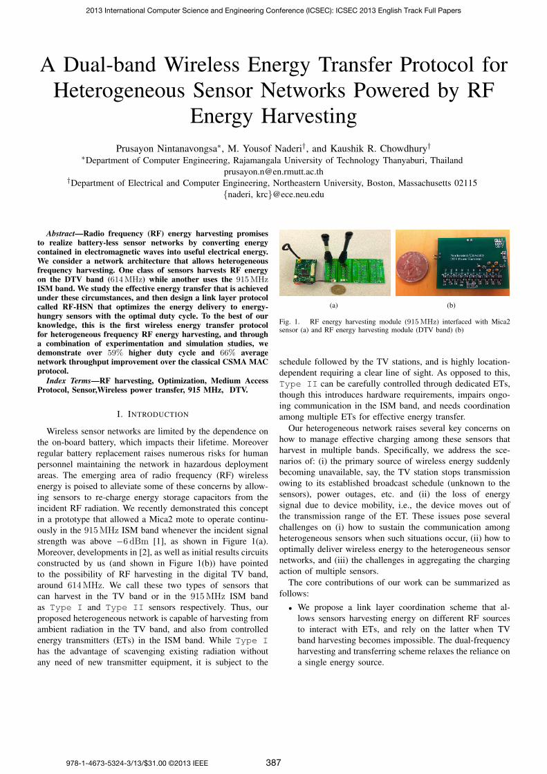
Wireless sensor networks are limited by the dependence onthe on-board battery, which impacts their lifetime. Moreoverregular battery replacement raises numerous risks for humanpersonnel maintaining the network in hazardous deploymentareas. The emerging area of radio frequency (RF) wirelessenergy is poised to alleviate some of these concerns by allow-ing sensors to re-charge energy storage capacitors from theincident RF radiation. We recently demonstrated this conceptin a prototype that allowed a Mica2 mote to operate continu-ously in the 915MHz ISM band whenever the incident signalstrength was above −6 dBm [1], as shown in Figure 1(a).Moreover, developments in [2], as well as initial results circuitsconstructed by us (and shown in Figure 1(b)) have pointedto the possibility of RF harvesting in the digital TV band,around 614MHz. We call these two types of sensors thatcan harvest in the TV band or in the 915MHz ISM bandas Type I and Type II sensors respectively. Thus, ourproposed heterogeneous network is capable of harvesting fromambient radiation in the TV band, and also from controlledenergy transmitters (ETs) in the ISM band. While Type Ihas the advantage of scavenging existing radiation withoutany need of new transmitter equipment, it is subject to the
(a) (b)
Fig. 1. RF energy harvesting module (915MHz) interfaced with Mica2sensor (a) and RF energy harvesting module (DTV band) (b)
schedule followed by the TV stations, and is highly location-dependent requiring a clear line of sight. As opposed to this,Type II can be carefully controlled through dedicated ETs,though this introduces hardware requirements, impairs ongo-ing communication in the ISM band, and needs coordinationamong multiple ETs for effective energy transfer.Our heterogeneous network raises several key concerns on
how to manage effective charging among these sensors thatharvest in multiple bands. Specifically, we address the sce-narios of: (i) the primary source of wireless energy suddenlybecoming unavailable, say, the TV station stops transmissionowing to its established broadcast schedule (unknown to thesensors), power outages, etc. and (ii) the loss of energysignal due to device mobility, i.e., the device moves out ofthe transmission range of the ET. These issues pose severalchallenges on (i) how to sustain the communication amongheterogeneous sensors when such situations occur, (ii) how tooptimally deliver wireless energy to the heterogeneous sensornetworks, and (iii) the challenges in aggregating the chargingaction of multiple sensors.The core contributions of our work can be summarized as
follows:
• We propose a link layer coordination scheme that al-lows sensors harvesting energy on different RF sourcesto interact with ETs, and rely on the latter when TVband harvesting becomes impossible. The dual-frequencyharvesting and transferring scheme relaxes the reliance ona single energy source.
2013 International Computer Science and Engineering Conference (ICSEC): ICSEC 2013 English Track Full Papers
978-1-4673-5324-3/13/$31.00 ©2013 IEEE 387

0100
200300
400
46
810
120
1
2
3
Time (sec)RF Power (dBm)
Vol
tage
(V
)
Fig. 2. The functional representation of the charging phase [14]
• We provide formulations for the optimal charging timefor the energy transfer by the ETs, and combine varioushardware platforms developed in prior work [1] underone operational protocol.
The rest of this paper is organized as follows: In Section II,we give the related work. Section III describes preliminaryexperiments used to motivate and design the RF-HSN protocoldetailed in Section IV. The simulation results are presented inSection V. Finally, Section VI concludes our work.
II. RELATED WORK
RF energy harvesting mechanisms can be primarily classi-fied as ambient RF energy harvesting and controlled RF energyharvesting. Ambient RF energy harvesting systems convertambient RF signals such as digital TV broadcasting, cellularBase Transceiver Station (BTS), and ambient Wi-Fi radiowaves into electrical energy to power RFIDs and sensor nodes.However, controlled RF energy harvesting systems use dedi-cated energy transmitters (i.e. wireless chargers) to generateand transfer RF waves with deliberate power intensity. Parkset al. [15] demonstrated a sensor node harvesting ambientRF energy from both digital TV and cellular radio wavesthat operates at a distance of 10.4 km from a 1 MW UHFtelevision broadcast tower, and over 200 m from a cellularbase transceiver station. An ambient RF energy scavenger thatharvest the RF power of a TV signal through an inkjet-printeddipole antenna and a charge pump was shown in [16] and[17]. The multi-channel OFDM nature of TV signals has beenexploited in [2] for powering an embedded microcontroller.Shigeta et al. [18] introduced a capacitor-leakage-aware dutycycle control method for sensor nodes powered with digitalTV broadcasting signal waves, which captures the long-termand short-term fluctuations of TV signals due to the scheduledfacility. Dolgov et al. [19] designed a power managementsystem for online low power RF energy harvesting of ambientcellular waves from the BTS. Moreover, Olgun et al. [20]developed a technique to harvest ambient Wi-Fi radio wavesat 2.45 GHz for powering a temperature and humidity sensorwith a LCD.
Specific to the scenario of controlled RF energy harvesting,feasibility studies, prototype implementations, medium accesscontrol protocols, and duty-cycle adoptions have been exploredin the recent past. Specifically, device characterization and
0.10.15
0.2
1.52
2.53
3.50
5
10
15
20
Capacitor size (F)
Tim
e (s
ec)
Voltage (V)
Fig. 3. Effect of capacitor sizes during capacitor discharging [14]
cross-layer protocol design for controlled RF energy har-vesting sensors are presented in [1]. Two cross-layer routingprotocols that either utilize local measurements on the har-vesting capability of a node (i.e., device agnostic), or employa joint hardware-software optimization (i.e., device specific)are presented in [14]. The centralized approach in [7], and itsassociated analytical model in [8], are concerned with a duty-cycle based energy harvesting scheme, though our methodrelies on the more general purpose de-centralized control.In [9], the authors describe conventional MAC protocols,
such as the classical TDMA and variants of ALOHA under apacket deliverability metric, assuming out-of-band controlledRF energy transfer. In [22] , the authors model a CSMA-based MAC protocol with ARQ error control mechanismfor energy harvesting sensor networks through an analyticalframework leveraging stochastic semi-markov models. TheToken-MAC protocol for RFID systems in [23] enables fairaccess to the medium for all tags powering by controlled RFwaves requiring neither a-priori knowledge of the tags norsynchronization. The authors in [21] introduced an energytransfer mechanism and medium access technique to optimizeenergy delivery to desirous sensor nodes in homogeneouswireless sensor network with controlled RF energy transfer.Different from the above works, RF-HSN is the first wirelessenergy transfer protocol for heterogeneous RF energy harvest-ing sensor networks.
III. PRELIMINARY EXPERIMENTS
In our previous work [14], we conducted a set of exper-iments to characterize the relationship between the receivedpower P , the capacitor C that will be charged by the energyharvesting device, and the output voltage V up to which thecapacitor can be charged through real measurements of ourenergy harvesting equipped sensor. The classical approach ofusing the power and voltage relationship of the capacitor,i.e., V = Vo(1 − e
t
RC ) cannot be directly applied to obtainthe charging time t. This is because the harvesting circuit iscomposed of non-linear and reactive components (Schottkydiodes, inductors and capacitors) whose efficiency and reac-tance vary with the incident signal or power level. Severaladditional circuit enhancements exist, such as dynamicallyswitching between multiple stages of the basic voltage mul-tiplier circuit which cannot be obtained from a simple study
2013 International Computer Science and Engineering Conference (ICSEC): ICSEC 2013 English Track Full Papers
388
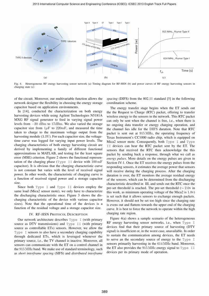
(a) (b) (c)
Fig. 4. Heterogeneous RF energy harvesting sensor network (a) Timing diagram for RF-HSN (b) and power curves of RF energy harvesting sensors incharging state (c)
of the circuit. Moreover, our multivariable function allows thenetwork designer the flexibility in choosing the energy storagecapacitor based on application environments.
In [14], conducted the characterization on both energyharvesting devices while using Agilent Technologies N5181AMXG RF signal generator to feed in varying signal powerlevels from −20 dBm to 17dBm. We also varied the storagecapacitor size from 1μF to 220mF, and measured the timetaken to charge to the maximum voltage output from theharvesting module (3.3V). For each capacitor size, the voltage-time curve was logged for varying input power levels. Thecharging characteristics of both energy harvesting circuit arederived by implementing a family of different functionalapproximations in MATLAB, and testing for the least squareerror (MSE) criterion. Figure 2 shows the functional represen-tation of the charging phase (Type II device with 100mFcapacitor). It is obvious that the charging characteristic curveis not constant but varies with the level of received signalpower. In other words, the characteristic of charging curve isa function of received signal power and a storage capacitorsize.
Since both Type I and Type II devices employ thesame load (Mica2 sensor mote), we only have to characterizethe discharging characteristic once. Figure 3 shows the dis-charging characteristic of the device with various capacitorsizes). Note that the operational time of the devices is afunction of the residual voltage and a storage capacitor size.
IV. RF-HSN PROTOCOL DESCRIPTION
Our network architecture describes Type I (with primarysource as DTV transmissions) and Type II (with primarysource as controllable ETs) sensors. However, we allow theType I sensors to also have a secondary charging capabilitythrough dedicated ETs, which is leveraged whenever theprimary source, i.e., the TV channel is inactive. Moreover, allsensors can communicate with the ET on a control channel inthe 915MHz band. We make use of standard terminology, suchas short interframe spacing (SIFS) and distributed interframe
spacing (DIFS) from the 802.11 standard [5] in the followingcoordination scheme.
The energy transfer stage begins when the ET sends outthe the Request to Charge (RTC) packet, offering to transferwireless energy to the sensors in the network. This RTC packetcan only be sent when the channel is free, i.e., when there isno ongoing data transfer or energy charging operation, andthe channel lies idle for the DIFS duration. Note that RTCpacket is sent out at 915MHz, the operating frequency ofTexas Instrument’s CC1000 radio chip, which is equipped onMica2 sensor mote. Consequently, both Type I and TypeII devices can hear the RTC packet sent by the ET. Thesensors that received the RTC then acknowledge the thispacket by sending back a response, through what we call asenergy pulses. More details on the energy pulses are given inSection IV-1. Once the ET receives the energy pulses from theresponding sensors, it estimates the average power that sensorswill receive during the charging process. After the chargingduration is over, the ET monitors the average residual energyof the sensors, which can be determined from the dischargingcharacteristic described in III, and sends out the RTC once thepre-set threshold is reached. The pre-set threshold (∼ 2.0v inthis work, as minimum operating voltage of the Mica2 is 1.8v)is set such that it allows sensors to exchange enough packets.However, it should not be set too high since the charging rateis evens out and flattens towards the upper end of the chargingcurve. It is best to force the network to operate within the highcharging rate region.
Figure 4(a) shows a sample scenario of the heterogeneousRF energy harvesting sensor networks, i.e., when Type Idevices find that their primary source of harvesting (DTVsignal) is insufficient or, in the worst case, unavailable. In orderto sustain the communication among devices, the ET needsto serve an the secondary source of energy to the Type Isensors primarily harvesting in the 614MHz band. Moreover,the ET also provides the 915MHz energy signal to Type IIdevices per its primary mode of operation.
2013 International Computer Science and Engineering Conference (ICSEC): ICSEC 2013 English Track Full Papers
389

1) Grouping of the responding sensors: The sensors thathear the RTC packet reply back with a single, constant energypulse called Clear to Charge (CTC). Since there are twotypes of devices harvesting energy at different frequencies,the constant energy pulse is sent out on either 614MHzor 915MHz, depending on the operating frequency of theharvesting module equipped, i.e., Type I devices respondwith 614MHz constant energy pulse and Type II devicesrespond with 915MHz constant energy pulse. The constantenergy pulse is emitted in a time slot, beginning from theinstant of completion of the RTC packet, as shown in Fig-ure 4(b). Consequently, Type I devices transmit constantenergy pulses in the same time slot that Type II devicestransmit their constant energy pulses. Note that there will beno interference in differentiating the band of received energypulses at the ET since Type I and Type II devices respondto the RTC packet in different spectrum bands. Referring againto the time slot in Figure 4(b), the CTC pulses sent by TypeI devices at 614MHz is shown in black while CTC pulsessent by Type II devices at 915MHz is shown in gray. TheET that sent the initial RTC estimates the time it needs totransmit the energy signal (charging time) based on the signalstrength of the received CTC pulses on both frequencies. Thisarrangement of using the CTC pulses allows the sensors tobe simple in design, and removes the concern of collisionsin the reply packet. Unlike classical data communication, itis not important for the ET to know the required energyof each sensor. Rather, the energy requirement calculationsare based on how much energy is needed by the two typeof devices separately. We define this cumulative energy asE
Type IRX and E
Type IIRX , respectively, which are calculated by
the RTC issuing ET from the received pulses of both frequencybands. Each slot time is 10μs in our work, allowing a veryfast response time. The purpose of differentiating the energyrequirement from the two group of devices is useful in thenext stage, where an optimization function returns the optimalenergy transfer with the highest duty cycle.
2) Optimization function for optimal energy delivery: Theaim of the optimization formulation is to maximize the energytransfer EMax
RX = EType IRX +E
Type IIRX to the coverage area of
the ET with the highest duty cycle. The energy transferredby the RF signal at each frequency is the time integral ofthe power (charging characteristic) curve at the correspondingfrequency. Note that the power curve is a function of thereceived signal strength (RSS) and the charging time. Thus, theuseful components that need to be maximized are two termsof (2), which give the total energy transfer to both Type Iand Type II devices.
Given : PcurveI(RSSI , tch), P curveII(RSSII , tch)
To find : tch (1)
To Maximize :
EMax
RX =
∫tch
PcurveI(RSSI , tch)dt
+
∫tch
PcurveII(RSSII , tch)dt (2)
Subject to :
d(PcurveI(RSSI , tch))
dt+
d(PcurveII(RSSII , tch))
dt
−
d(Pdischarge(tch))
dtis maximum (3)∫
tch
PcurveI(RSSI , tch)dt > EminI(4)
∫tch
PcurveII(RSSII , tch)dt > EminII(5)
The aim of this optimization framework is to maximize areaunder the devices’ power curves, subject to several constraintswhich are explained below:
• The sum of derivatives of power curves of Type I,Type II devices, and the discharging curve, evaluatedat the charging time t = tch is maximum. In other words,the aggregate rate of charging of both Type I and TypeII devices, subtracted by the discharging rate, are at itsmaximum. This put a constraint on achieving the highestduty cycle.
• The amount of energy transfer to Type I and Type IIdevices has to be larger than the lowest amount of energyrequired for Type I and Type II devices to be in theoperational state, respectively.
With the resulting dual-frequency wireless energy transfer,both groups of devices can be simultaneously active. The finalpart of this stage involves letting both Type I and TypeII devices know that they are about to enter the chargingstate through an Acknowledgement (ACK) packet. This packetprovides both types of devices the expected charging timeand hence, the following inactive time, according to theoptimization results. After a short SIFS wait period followingthe ACK, the ET begin its transmission. Consequently, the ETstarts to deliver the energy to sensors at different frequencies,that is, 614MHz charging energy signal for Type I devicesand 915MHz charging energy signal for Type II devices,respectively. In case of loss of the RTC packet due to packetcollision or bad channel conditions, the contention windowsare re-set to the minimum width, thereby initiating an imme-diate subsequent retry.
V. SIMULATION RESULTS
In this section, we thoroughly evaluate our proposed pro-tocol using our custom simulator, developed in MATLAB.We observe the behavior of RF-HSN protocol with respect todifference in average received power of Type I and TypeII devices. This simulation setup represents the scenario de-scribed in I, i.e., when Type I find that their primary sourceof harvesting is insufficient or unavailable. The simulationparameters are set as follows: The energy harvesting modulesparameters are from [1]. We model the ET on the Powercastertransmitter [4], which is capable of transmitting continuouswaves (CW) modulation at 3W EIRP. However, we impose anadditional feature on the ET requirement, that is, the ability toemit the CW modulation at 614MHz and 915MHz, simulta-neously. The operational characteristics of the sensor, such asenergy spent in transmission, reception, idle listening, channel
2013 International Computer Science and Engineering Conference (ICSEC): ICSEC 2013 English Track Full Papers
390

bandwidth, etc. are from MICA2 specifications [13]. Unlessspecifically stated, 10 sensor nodes, 5 of each type, and 1 ETare deployed uniformly at random in 40 x 40 m2 grid. TypeII devices are randomly placed such that the average receivedpower is measured 12 dBm. On the contrary, the placementof Type I devices are randomly chosen to have variousaverage received power, ranging from 4 dBm to 12 dBm.The default packet size is 50 Bytes and the sender/receiverpairs are chosen randomly from Type I device to TypeII groups. We compare the proposed RF-HSN protocol withthe modified unslotted CSMA. RF-HSN features the energydelivery optimization by dynamically adjusting the charginglevel (hence, the charging duration), with specific constraints,in order to achieve an optimal energy delivery. The unslottedCSMA modified from the description in [6] provides the basecase and reference protocol for comparison. The sensors arealways charged to the maximum level, at 3.3V and we assumesaturated condition wherein sensors always have a packet totransmit.
A. Impact on average energy harvesting rate
Here, we investigate the effect of difference in averagereceived power for the Type I and Type II devices de-pending on average energy harvesting rate. Figure 5 showsthe effect of the average received power of Type I devicesfor both RF-HSN and modified CSMA protocols. As statedearlier, the placement of Type II devices is fixed with theaverage received power of 12 dBm while Type I devicesare deployed with varied averaged received power, rangingfrom 4 dBm to 12 dBm. It is not surprising that both RF-HSNand the modified CSMA deliver monotonically increasingaverage energy harvesting rate with increasing received powerof Type I devices. However, the benefit of energy deliveryoptimization, incorporated in RF-HSN, greatly improves theaverage energy harvesting rate. The improvement is over 59%when the average received power of Type I devices is at4 dBm and tapered down to 20% when the average receivedpower of Type I devices is equal to that of Type IIdevices, at 12 dBm. The reduction in an improvement is aresult of steeper and less deflected power curves of both TypeI and Type II devices in higher received power regime,which gives less room for optimization of RF-HSN protocol.
B. Impact on duty cycle of the network
The impact of average received power of Type I deviceson the duty cycle is shown in Figure 6. It is obvious that RF-HSN yields higher duty cycle throughout the range. When theaverage received power of Type I devices is at 4 dBm, RF-HSN yields 7.51% duty cycle while only 3.86% duty cycleis achieved by the modified CSMA, over 94.66% higher induty cycle. The duty cycle plot also resembles to that of theaverage energy harvesting rate plot, that is, the duty cyclegain decreases as average received power of Type I devicesincreases. At 12 dBm of average received power of Type Idevices, RF-HSN yields 34.46% higher duty cycle than themodified CSMA.
4 6 8 10 120
10
20
30
40
50
Average Received Power of Type I Devices (dBm)
Ave
rage
Har
vest
ing
Rat
e (m
V/s
)
RF−HSNModified CSMA
Fig. 5. Effect of the average received power of Type I devices on averageenergy harvesting rate
4 5 6 7 8 9 10 11 120
0.05
0.1
0.15
0.2
0.25
0.3
0.35
Average Received Power of Type I Devices (dBm)
Dut
y C
ycle
RF−HSNModified CSMA
Fig. 6. Effect of the average received power of Type I devices on dutycycle
C. Impact on average packet delay
One of the major concerns of RF energy harvesting sensornetworks is the inactive period of the sensors due to energyreplenishing (charging process). It is crucial to investigate theaverage packet latency of the proposed protocol, especiallywhen time-sensitive applications are involved. Figure 7 showsthe impact on average packet delay against various averagereceived power of Type I devices, and complements the dutycycle plot shown earlier. Since the duty cycle is defined asthe sensor’s active period over the sum of sensor’s active andinactive period, it does not capture the information about anabsolute sensor’s inactive time, but rather a relative active time.It is clear that RF-HSN offers a considerably less averagepacket delay when the average received power of Type Idevices is at 4 dBm, only 13 s (RF-HSN) compared to 310 s(modified CSMA). Moreover, RF-HSN is not susceptible tothe fluctuation of average received power of Type I devices.As shown in Figure 7, the average packet delay of RF-HSNexperiences considerably less fluctuation when compared tothat of modified CSMA.
D. Impact on network throughput
Figure 8 depicts the network throughput when averagereceived power of Type I devices is varied from 4 dBm to12 dBm. Similar to the earlier case, RF-HSN outperforms themodified CSMA in terms of network throughput throughoutthe range. On average, RF-HSN yields approximately 66%higher network throughput than the modified CSMA.
2013 International Computer Science and Engineering Conference (ICSEC): ICSEC 2013 English Track Full Papers
391

4 5 6 7 8 9 10 11 120
50
100
150
200
250
300
350
Average Received Power of Type I Devices (dBm)
Ave
rage
Pac
ket D
elay
(s)
RF−HSNModified CSMA
Fig. 7. Effect of the average received power of Type I devices on averagepacket delay
4 6 8 10 120
1
2
3
4
5
6
7
Average Received Power of Type I Devices (dBm)
Thr
ough
put (
Kbp
s)
RF−HSNModified CSMA
Fig. 8. Effect of the average received power of Type I devices on averagenetwork throughput
VI. CONCLUSIONS
The RF-HSN protocol defines new metrics in wirelessenergy transfer for heterogeneous RF energy harvesting sen-sor networks through wireless energy delivery optimization.This optimization ensures the optimal energy delivery withthe highest duty cycle. Our new architecture for RF en-ergy harvesting will allow seamless interoperability amongheterogeneous sensors, harvesting at different RF frequencysources, especially leveraging the large ambient energy presentin the DTV band. Our previous work, on the RF energyharvesting platform fabrication and characterization of theircharacteristics, is used to shape the deign goals of the RF-HSN protocol under rigid experimental constrains. Simulationresults reveals that RF-HSN largely outperforms the modifiedCSMA. The higher duty cycle, together with considerablylower average packet latency, make the RF-HSN protocola preferred choice for heterogeneous RF energy harvestingsensor networks.
ACKNOWLEDGMENT
The authors would like to thank David R. Lewis for hiscontribution. This material is based upon work supported bythe US National Science Foundation under Grant No. CNS-1143681.
REFERENCES
[1] P. Nintanavongsa, U. Muncuk, D. R. Lewis, and K. R. Chowdhury, DesignOptimization and Implementation for RF Energy Harvesting Circuits.
IEEE Journal on Emerging and Selected Topics in Circuits and Systems,vol. 2, no. 1, pp. 24–33, Mar. 2012.
[2] R. J. Vyas, B. B. Cook, Y. Kawahara, and M. M. Tentzeris, E-WEHP: A Batteryless Embedded Sensor-Platform Wirelessly PoweredFrom Ambient Digital-TV Signals. IEEE Transactions on MicrowaveTheory and Techniques, vol. 61, no. 6, pp. 2491–2505, Jun. 2013.
[3] C. M. Vigorito, D. Ganesan, and A. G. Bart, Adaptive Control of DutyCycling in Energy-Harvesting Wireless Sensor Networks. Proc. of IEEESECON, pp. 21–30, Jun. 2007.
[4] Powercast Corporation, Lifetime Power Evaluation and Development Kit.[Online] http://www.powercastco.com/products/development-kits/
[5] IEEE 802.11, Wireless LAN Medium Access Control (MAC) andPhysical Layer (PHY) Specification. 1999.
[6] Z. A. Eu, H.P. Tan, and W. K. G. Seah, Design and performance analysisof MAC Schemes for Wireless Sensor Networks Powered by AmbientEnergy Harvesting. Ad Hoc Networks, vol. 9, no. 3, pp. 300–323, 2011.
[7] J. Kim and J. W. Lee, Energy Adaptive MAC Protocol for Wireless SensorNetworks with RF Energy Transfer. Proc. of IEEE Intl. Conference onUbiquitous and Future Networks (ICUFN), pp. 89–94, 2011.
[8] J. Kim and J. W. Lee, Performance Analysis of the Energy AdaptiveMAC Protocol for Wireless Sensor Networks with RF Energy Transfer.Proc. of IEEE Intl. Coverage and Transmission Conference (ICTC), pp.14–19, 2011.
[9] F. Iannello, O. Simeone, and U. Spagnolini, Medium Access ControlProtocols for Wireless Sensor Networks with Energy Harvesting. IEEETransactions on Communications, vol. 60, no.5, pp. 1381–1389, May.2012.
[10] M.K. Watfa, H. AI-Hassanieh, S. Selman, Multi-hop wireless energytransfer in WSNs. IEEE Communication Letter, vol. 15, no. 12, pp.1255–1277, Oct. 2011.
[11] A. Karalis, J. D. Joannopoulos, and M. Soljacic, Efficient wirelessnonradiative mid-range energy transfer. Annals of Physics, vol. 323, no.1, pp. 34–48, Jan. 2008.
[12] J. Curty, M. Declercq, C. Dehollain, N. Joehl, Design and Optimizationof Passive UHF RFID Systems, Springer, 2007.
[13] Crossbow Technology, Inc. [Online] http://www.xbow.com/[14] P. Nintanavongsa, R. Doost, M. Di Felice, and K. R. Chowdhury, Device
characterization and cross-layer protocol design for RF energy harvestingsensors. Elsevier Journal of Pervasive and Mobile Computing, vol. 9, no.1, February 2013.
[15] A. Parks, A. Sample, Y. Zhao, and J. R. Smith, A wireless sensingplatform utilizing ambient RF energy. IEEE Topical Meeting on WirelessSensors and Sensor Networks (WiSNET), Austin, TX, Jan 2013.
[16] H. Nishimoto, Y. Kawahara, and T. Asami, Prototype implementation ofwireless sensor network using TV broadcast RF energy harvesting. 12thACM international conference adjunct papers on Ubiquitous computing,pp. 373–374, Copenhagen, Denmark, Sep 2010.
[17] R. Vyas, H. Nishimoto, M. Tentzeris, Y. Kawahara, and T. Asami,A battery-less, energy harvesting device for long range scavenging ofwireless power from terrestrial TV broadcasts. IEEE MTT-S InternationalMicrowave Symposium Digest (MTT), Montreal, Canada, June 2012.
[18] R. Shigeta, T. Sasaki, D. Minh Quan, Y. Kawahara, R. J. Vyas, M.M. Tentzeris, and T. Asami, Ambient-RF-Energy-Harvesting SensorDevice with Capacitor-Leakage-Aware Duty Cycle Control. IEEE SensorsJournal, pp. 1–10, July 2013.
[19] A. Dolgov, R. Zane, and Z. Popovic, Power management system foronline low power RF energy harvesting optimization. IEEE Transactionson Circuits and Systems I: Regular Papers, vol. 57, no. 7, pp. 1802–1811,July 2010.
[20] U. Olgun, C.-C. Chen, and J. Volakis, Design of an efficient ambientWi-Fi energy harvesting system. IET Microwaves, Antennas Propagation,vol. 6, no. 11, pp. 1200–1206, Aug 2012.
[21] P. Nintanavongsa, M.Y. Naderi, and K. R. Chowdhury, MediumAccess Control Protocol Design for Sensors Powered by Wireless EnergyTransfer. Proc. of IEEE International Conference on Computer Commu-nications (INFOCOM), pp. 150–154 , April 2013.
[22] M.Y. Naderi, S. Basagni, and K.R. Chowdhury, Modeling the ResidualEnergy and Lifetime of Energy Harvesting Sensor Nodes. Proc. of IEEEGlobal Telecommunications Conference (GLOBECOM), pp. 3394–3400,Dec. 2012.
[23] L. Chen, I. Demirkol, and W. Heinzelman, Token-MAC: A FairMAC Protocol for Passive RFID Systems. Proc. of IEEE GlobalTelecommunications Conference (GLOBECOM), pp. 1–5, Dec. 2011.
2013 International Computer Science and Engineering Conference (ICSEC): ICSEC 2013 English Track Full Papers
392


![HIGH-EFFICIENCY WIRELESS ENERGY TRANSMIS- SION …structures in the wireless energy transmission system [4,13]. In this paper, a high-e–ciency wireless energy transmission via magnetic](https://static.fdocuments.us/doc/165x107/5e31203a05720b0fbd15723a/high-efficiency-wireless-energy-transmis-sion-structures-in-the-wireless-energy.jpg)