A DESIGN FOR VERIFICATION APPROACH USING...
24
April 21, 2008 11:20 WSPC/123-JCSC 00405 Journal of Circuits, Systems, and Computers Vol. 16, No. 6 (2007) 859–881 c World Scientific Publishing Company A DESIGN FOR VERIFICATION APPROACH USING AN EMBEDDING OF PSL IN AsmL AMJAD GAWANMEH * and SOFI ` ENE TAHAR † Concordia University, Montreal, Quebec, H3G 1M8 Canada * [email protected] † [email protected] HAJA MOINUDEEN ‡ Poseidon Design Systems, Bangalore, India [email protected] ALI HABIBI ‡ MIPS Technologies, Inc., Mountain View, California, 94043 USA [email protected] In this paper, we propose to integrate an embedding of Property Specification Language (PSL) in Abstract State Machines Language (AsmL) with a top–down design for ver- ification approach in order to enable the model checking of large systems at the early stages of the design process. We provide a complete embedding of PSL in the ASM language AsmL, which allows us to integrate PSL properties as a part of the design. For verification, we propose a technique based on the AsmL tool that translates the code containing both the design and the properties into a finite state machine (FSM) representation. We use the generated FSM to run model checking on an external tool, here SMV. Our approach takes advantage of the AsmL language capabilities to model designs at the system level as well as from the power of the AsmL tool in generating both C# code and FSMs from AsmL models. We applied our approach on the PCI-X bus standard, which AsmL model was constructed from the informal standard specifica- tions and a subsequent UML model. Experimental results on the PCI-X bus case study showed a superiority of our approach to conventional verification. Keywords : PSL; abstract state machines; AsmL; model checking; PCI-X bus. 1. Introduction and Motivation With the advent of high technology applications, an increasingly evident need has been that of incorporating the traditional microprocessor, memories, and peripherals on a single silicon. System level modeling is used to overcome the prob- lem of the growth in complexity and size of systems combining different types of components, including microprocessors, DSPs, memories, embedded software, etc. ‡ This work was done while these authors were working at the Concordia University. 859
Transcript of A DESIGN FOR VERIFICATION APPROACH USING...

April 21, 2008 11:20 WSPC/123-JCSC 00405
Journal of Circuits, Systems, and ComputersVol. 16, No. 6 (2007) 859–881c© World Scientific Publishing Company
A DESIGN FOR VERIFICATION APPROACH USING ANEMBEDDING OF PSL IN AsmL
AMJAD GAWANMEH∗ and SOFIENE TAHAR†
Concordia University, Montreal, Quebec, H3G 1M8 Canada∗[email protected]†[email protected]
HAJA MOINUDEEN‡
Poseidon Design Systems, Bangalore, [email protected]
ALI HABIBI‡
MIPS Technologies, Inc., Mountain View, California, 94043 [email protected]
In this paper, we propose to integrate an embedding of Property Specification Language(PSL) in Abstract State Machines Language (AsmL) with a top–down design for ver-ification approach in order to enable the model checking of large systems at the earlystages of the design process. We provide a complete embedding of PSL in the ASMlanguage AsmL, which allows us to integrate PSL properties as a part of the design.For verification, we propose a technique based on the AsmL tool that translates thecode containing both the design and the properties into a finite state machine (FSM)representation. We use the generated FSM to run model checking on an external tool,here SMV. Our approach takes advantage of the AsmL language capabilities to modeldesigns at the system level as well as from the power of the AsmL tool in generatingboth C# code and FSMs from AsmL models. We applied our approach on the PCI-Xbus standard, which AsmL model was constructed from the informal standard specifica-tions and a subsequent UML model. Experimental results on the PCI-X bus case studyshowed a superiority of our approach to conventional verification.
Keywords: PSL; abstract state machines; AsmL; model checking; PCI-X bus.
1. Introduction and Motivation
With the advent of high technology applications, an increasingly evident needhas been that of incorporating the traditional microprocessor, memories, andperipherals on a single silicon. System level modeling is used to overcome the prob-lem of the growth in complexity and size of systems combining different types ofcomponents, including microprocessors, DSPs, memories, embedded software, etc.
‡This work was done while these authors were working at the Concordia University.
859

April 21, 2008 11:20 WSPC/123-JCSC 00405
860 A. Gawanmeh et al.
System level languages can fill the gap between the hardware description languages(HDLs) and traditional software programming languages. Therefore, the modelingand verification process of system level designs, at the early stage of the designprocess, is very challenging.
The verification of the systems at the early stages of the design process is aserious bottleneck in the system design flow. While simulation is the most widelyused verification technique, it is unable to guarantee the correctness of the designwith respect to its specification. On the other hand, model checking is consideredas a relevant technique to cover for simulation insufficiencies. Nevertheless, directmodel checking may not be feasible due to the complexity of the designs. Besides,the state explosion problem led, for complex systems, to the use of assertion-basedverification (ABV), where the property under verification is turned into a monitor,checked by simulation, and evaluated using coverage metrics. Therefore, there is aneed for verification solutions for industrial size designs at the system level.
Abstract State Machine (ASMs)1,14 is a formal specification method for soft-ware and hardware systems that has become successful for specifying and verifyingcomplex systems. The ASM formalism is used as a modeling language in a varietyof domains both in academic and industrial contexts.18 The ASM methodology ismathematically precise, yet general enough to be applicable to a wide variety ofproblem areas. The ASM thesis asserts that any computing system can be describedat its natural level of abstraction by an appropriate ASM. ASMs provide featuresto capture the behavioral semantics of programming and modeling languages, asa wide range of these languages were defined with this notion.18 There are manylanguages that have been developed for ASMs, the recent one is AsmL,15 whichwas developed at Microsoft Research. We chose this language, as a common level ofabstraction, to define an abstract simulator, and then model designs and properties.AsmL is integrated with Microsoft’s software development environment includingVisual Studio, MS Word, and Component Object Model (COM), where it can becompiled and connected to the .NET framework. AsmL effectively supports specifi-cation and rapid prototyping of different kinds of models. The AsmL tester (Asmlt)can also be used to generate finite state machines (FSM) or test cases.9
The Accellera Property Specification Language (PSL)23 was developed toaddress the lack of information about properties and design characteristics of regis-ter transfer level (RTL) models. It provides the means of specifying design proper-ties using a concise syntax with clearly defined formal semantics. PSL permits thespecification of a large class of design properties at four layers: Boolean, temporal,verification, and modeling. PSL is intended to be used for functional specificationto capture requirements regarding the overall behavior of a design on one hand,and as an input to verification tools using simulation or formal verification on theother hand.
In the work proposed in Ref. 7 we used a bottom–up approach in order toaccomplish verification for SystemC designs based on embedding PSL in AsmL,and using our ASM semantics for SystemC.6,17 We embedded PSL properties in

April 21, 2008 11:20 WSPC/123-JCSC 00405
A Design for Verification Approach Using an Embedding of PSL in AsmL 861
AsmL, to be able to reason about the behavior of the design, and its correctnessagainst its specification. Then, we used the AsmL tool in order to generate anFSM of the design model (including the properties). This approach enabled theverification of PSL properties on designs using classical model checking tools, forinstance SMV.19 For this, we translate the generated FSM into the input languageof the SMV tool.
In this paper, however, we use a top–down approach for the verification ofsystems at the first stages of the design process based on the design for verificationapproach proposed in Refs. 16 and 20. Here we start with an informal specificationof the system and model it with the Unified Modeling Language (UML) in order tohave a clear view of the design modules and their interactions. Then, we constructan AsmL model from the UML representation. This paper integrates this designfor verification approach into the verification methodology presented in Ref. 7 andapplies the methodology on to an industrial size case study of the PCI-X busstandard.22 We used the PCI-X bus to show the feasibility and performance ofour approach. The experimental results proved the practicality of our methodologyas a solution to the verification problem of system level designs.
The rest of the paper is organized as follows: Section 2 presents works relatedto that of ours. In Sec. 3, we provide the integration of the design for verificationapproach into the PSL–AsmL verification methodology. Section 4 describes ourembedding for PSL in AsmL. Section 5 illustrated our approach on the case studyof the PCI-X bus. Finally, Sec. 6 concludes the paper and points to a few futurework directions.
2. Related Works
In Ref. 13, Gordon used the semi-formal semantics in the PSL/Sugar documen-tation23 to create a deep embedding of the whole language in the HOL theoremprover.12 The author developed the formal definition of the full PSL language inHOL. The combination of PSL/Sugar and higher order logic is quite expressiveand provides temporal logic constructs as higher level syntactic sugar for higherorder logic, thereby enabling properties to be formulated elegantly. Gordon et al.11
described how to “execute” the formal semantics of PSL using HOL and investigatedthe feasibility of implementing useful tools to conduct automatic verification ofPSL from the formal semantics. They implemented two experimental tools: aninterpreter that evaluates whether a finite trace, satisfies a PSL formula, and acompiler that converts PSL formulas to checkers in an intermediate format suitablefor translation to HDL to be included in simulation test-benches. However, theydid not provide any framework for the verification of PSL for any implementationlanguage.
In a similar work, Claessen and Martensson2 defined an operational semanticsfor a weak fragment of PSL, mainly the safety property subset of PSL, and thenproved the correctness of these semantics with respect to a denotational semantics.

April 21, 2008 11:20 WSPC/123-JCSC 00405
862 A. Gawanmeh et al.
They do not provide definitions for all PSL operators like clock operators andsequential composition, and yet, there is no execution for these semantics thatprovides verification solution.
There has been a potential work on ASM verification as discussed by Borger andStark.1 Applying model checking algorithms on ASM was introduced in Ref. 28,where transformation algorithms are provided to transform ASM models into dif-ferent verification tools. Two approaches were adopted: the first provides a trans-formation to the language of a symbolic model checker, SMV,28 and the second tothe MDG verification tool.8 The work we present here, is different since it providesa solution for the verification problem of system level design languages based onsemantics definitions and executions of PSL in AsmL.
Wallace26 used the ASM notation to define operational semantics of C++ pro-gramming language focusing on its object-oriented and other advanced features likeclasses, inheritance, operator overloading, virtual functions, templates, and excep-tion handling. Definitions for other languages semantics such as Prolog, SDL, andStandard ML using ASM can be found in Ref. 18. These semantics definitions pro-vide no execution of the language semantics itself in order to give a solution todesign problems like verification.
ASM has been widely used to define the operational semantics of programminglanguages like C++, Prolog, SDL, and Standard ML.18 However, these semanticsdefinitions provide no execution of the language semantics itself in order to give asolution to design problems like verification.
Other related work to ours concerns finite-state verification including the workon Bandera project5 interfacing Java code to model checking tools like SMV andSPIN by applying program analysis, abstraction, and transformation techniques.In its actual status, Bandera cannot handle SystemC designs because any analysisof a SystemC code must go through the whole simulation environment as well asSystemC-defined data-types and classes. In Ref. 10 an approach is presented to addassertion checkers to SystemC. This previous work is different from our method-ology since the properties in the study of Ref. 10 are restricted to the notationof property checker from Infineon Technologies AG, then translated to synthesiz-able SystemC instructions while we consider any PSL property. In his PhD thesis,Habibi16 proposed a combination of various techniques to verify system level lan-guages, in particular SystemC. His approach combined static code analysis, modelchecking, and assertion-based verification for system level designs. Habibi focused onthe verification problem of the SystemC case, while this work extends his approachto provide a top–down design for verification approach.
There exists some other related works to ours in the context of PCI technologiesdesign and verification environment. Shimizu et al.24 presented a specification ofthe PCI bus as a Verilog monitor. Oumalou et al.21 implemented the PCI bus inSystemC. In Ref. 4 a bridge for PCI Express and PCI-X was designed in Verilog atRTL and also verified and synthesized. Chang et al.3 proposed a simulation-basedPCI-X verification environment using C and Verilog. Wang and Wen27 proposed a

April 21, 2008 11:20 WSPC/123-JCSC 00405
A Design for Verification Approach Using an Embedding of PSL in AsmL 863
similar verification environment as in Ref. 3 for PCI-X bus functional models usingVERA. Yu et al.29 extended the verification environment in Ref. 3 to support PCI,PCI-X, and PCI-Express in a single platform.
3. Verification Methodology
Our methodology is a top–down approach for verification of systems at the initialstages of the design process based on the design for verification approach proposedin Refs. 16 and 20. Here, we start with an informal specification of a system andmodel it with the Unified Modeling Language (UML) in order to have a clear view ofthe design modules and their interactions; we use UML class and sequence diagramsin order to capture all the design requirements efficiently. Class diagrams are usedto represent all the core components of the design and the sequence diagrams areused to model all the sequences of various transactions. The reason of this UMLmodeling is to represent the system graphically and to enable the representationof the notion of sequences of the bus transaction using sequence diagrams. Besidesusing our UML representation, designers can model the bus in any Object-Orientedlanguages.
The next step is to construct an AsmL model from the UML representation. Thetranslation from the UML representation to AsmL is manual but straightforward.We map the UML classes into AsmL classes and the sequence diagrams are usedto represent the order of method executions in AsmL. Unlike the UML model, theAsmL model can be executed and validated. The properties of the bus design arespecified in PSL and embedded with the AsmL model. They are basically extractedfrom the sequence diagrams and encoded in the PSL syntax. Next, model checkingis performed on the AsmL model using AsmL tester (Asmlt). The model checkingprocess ends to: (1) a completion either with success or failure of the property; or(2) a state explosion. In case of failure, we correct the UML representation andredo the AsmL translation. This procedure is repeated until all the properties passwith success or do not get completed.
Figure 1 shows a sketch of our methodology for the embedding and verificationof PSL in AsmL. Properties are embedded in every state in the FSM generatedby the Asmlt and is represented by two Boolean state variables. The first repre-sents whether a property can be evaluated or not and the second denotes the stateof the property in the current state. A correct verification process results in thegeneration of the system’s FSM. If the property is not verified, then an error tracewould be generated. In the case of state explosion, the FSM generation will becomeunsuccessful.
This methodology is different from our previous work (Ref. 7) in two majordirections: the considered model under verification, and the way we perform modelchecking. The work in Ref. 7, which is highlighted in the dashed box in Fig. 1,targets low-level designs in SystemC, while this work is a design for verificationapproach starting from informal specifications. On the other hand, the way we

April 21, 2008 11:20 WSPC/123-JCSC 00405
864 A. Gawanmeh et al.
PSL Property
ASM/PSL PropertyGenerator
Informal DesignSpecifications
Embedded PSLSemantics
(AsmL)
AsmL Tool(AsmL Compiler)
Design Modeledin AsmL
PSL PropertyModeled in AsmL
Test ScenariosModel and PSLProperty in C# FSM with PSL-AsmL
Property Evaluation
Assertion Parser
UML Design
Fig. 1. Design for verification methodology based on embedding PSL in AsmL.
perform model checking here is different from the classical approach used in Ref. 7,where an external tool is used to perform model checking. In this approach, however,once the modeling in AsmL is done, we include the defined PSL properties in theAsmL design. Then, the AsmL design with the properties is fed to the Asmlt testerthat generates an FSM of the model. Using Asmlt, we perform state explorationwhich gives the notion of model checking. We encode the properties evaluation inevery state, which enables checking its correctness on-the-fly while executing theFSM generation algorithm (part of the Asmlt).9 Any incorrect property detectionhalts the reachability algorithms and outputs a sub-portion from the complete FSM,which can be used to identify counter-examples.
In the next section, we show the details of embedding the layers of PSL in AsmL;then, we apply our methodology on an industrial size case study of the PCI-X bus,where we show the efficiency of the top–down design for verification approach, andwe verify several properties on the bus.
4. Embedding PSL in AsmL
PSL is an implementation-independent language to define properties (also calledassertions). It does not replace, but complements existing verification methodolo-gies like VHDL and Verilog test-benches. PSL presents a different view of thedesign and may imply FSMs in the implementation. The syntax of PSL is very

April 21, 2008 11:20 WSPC/123-JCSC 00405
A Design for Verification Approach Using an Embedding of PSL in AsmL 865
declarative and structural which leads to sustainable verification environments.Both VHDL and Verilog flavors are provided. PSL consists of four layers basedon functionality:The Boolean layer to build expressions which are used in other layers, specificallythe temporal layer. Boolean expressions are evaluated in a single evaluation cycle.The temporal layer is used to describe the properties of the design; in addition tosimple properties, this layer can describe properties that involve complex temporalrelations. Temporal expressions are evaluated over a series of evaluation cycles.The verification layer is used to tell the verification tool what to do with theproperties described by the temporal layer.The modeling layer is used to model behavior of design inputs for formal verifica-tion tools, and to model auxiliary parts of the design that are needed for verification.
This layered approach allows the expression of complex properties from simpleprimitives. A property is built from three types of building blocks: Boolean expres-sions, sequences, which are themselves built from Boolean expressions, and finallysubordinate properties. Sequences, referred to as SEREs (Sequential Extended Reg-ular Expressions), are used to describe a single- or multicycle behavior built fromBoolean expressions.
There are two ways to embed PSL properties into the design, either into thedesign code itself or by adding them as external monitors. We adopted the firstapproach, where all parameters of PSL properties are defined as objects. The objec-tive of the embedding is to reuse PSL properties, as embedded in AsmL, at lowerdesign levels since the AsmL tool can automatically compile them into C# or.NET code.
PSL properties are defined in a hierarchical way inspired from the hardwaredesign modular concept. For this reason we defined the embedding in a similarstructure, where all the components are defined as objects and every PSL layerextends its lower layer using the inheritance feature of AsmL as described.
4.1. Boolean layer
This layer is the basic layer of PSL. Even though it is called Boolean layer, itincludes types other than Boolean such as integers and bit vectors. We embeddedthis layer in AsmL by defining classes for all types and expressions including theirmethods. Our embedding is based on the semi-formal semantics presented in thereference manual,23 and the formal semantics definition in HOL.13
The embedding of the PSL Boolean layer mainly includes the following:
(1) Expression type class includes the five basic types: Boolean, PSLBit,PSLBitVector, Numeric, and String. Both Boolean and String types are directlyinherited from the AsmL’s AsmL.Boolean and AsmL.String, respectively. ThePSLBit type is constructed using the enumerated structure One, Zero, X, and Z.The PSLBitVector type extends the PSLBit type and offers additional opera-tions such as access to the bit vector contents. Finally, the PSLNumeric type

April 21, 2008 11:20 WSPC/123-JCSC 00405
866 A. Gawanmeh et al.
extends the AsmL Integer type (AsmL.Integer) by adding some conversionmethods from PSLBitVector to integers and vice versa.
(2) PSL Expressions construct properties using the implication and equivalenceoperators. Both operators are built using AsmL’s implies operator.
(3) PSL Built Functions include all the functions defined by PSL to operate atthe Boolean layer. We distinguish here two methods: a method that providesthe previous values of a variable (e.g., prev()) and a method that provides thefuture values of a variable (e.g., next()). For both methods, we define a queuestructure that extends the PrimitiveArray class of AsmL, to store the values ofthe signals (PSL Bit Vector Queue for the PSLBitVector type). We note thatall the methods over the Boolean layer are overridable according to the type ofthe input. This approach simplifies writing the properties in AsmL syntax asthey will look very close to the PSL structure.
Figure 2 shows the AsmL code for PSL Bit V ector class with the methodIsInitialized() that checks if a BitVector is initialized.
4.2. Temporal layer
The most important part of this layer is the Sequential Extended Regular Expres-sions (SERE) feature, which embedding mainly includes:
(1) Sequential Expressions, where a SERE is defined as an AsmL sequence ofBoolean. It offers several operations to construct, manipulate, and evaluatethe SERE expression. PSL Sequence extends the PSL SERE class. It addsoperations needed to create and update the SERE.
(2) Properties in the form of operations necessary to create properties from sequen-tial expressions. It also controls when and how the sequence is to be verified(i.e., the property “verify the sequence is true after n states” is defined asPSL Property.EvaluateNext(n)).
Figure 3 shows the example of the PSL SERE.Evaluate(), which checks if asequence is true in a certain path. This method is activated according to an INITsignal that must be set by the property.
class PSL_BitVector
var m_size as Integer = 1
var m_sum as Integer = 0
var m_array as PrimitiveArray of PSL_Bit = null
public IsInitialized() as Boolean
non_initailized = (exists x in {1..m_size} where
(m_array(x).m_value = X or m_array(x).m_value = Z))
return not non_initailized
Fig. 2. AsmL embedding of PSL BitVector.

April 21, 2008 11:20 WSPC/123-JCSC 00405
A Design for Verification Approach Using an Embedding of PSL in AsmL 867
class PSL_SERE
var m_size as Integer = 0
var m_seq as Seq of Boolean
var m_actualState as Integer = 0
var m_evaluation as SERE_Evaluation = NOT_STARTED
var m_evaluationState as SERE_Evaluation = NOT_STARTED
public Evaluate() as SERE_Evaluation
require m_evaluationState = INIT
if(me.m_seq(m_actualState) = false)
m_evaluation := FAILED
return FAILED
else
if m_actualState = m_size
m_actualState := m_actualState + 1
return IN_PROGRESS
else
m_actualState := 0
return SUCCEEDED
Fig. 3. AsmL embedding of PSL SERE.
4.3. Verification layer
This layer is intended to tell the verification tool how to perform the verificationprocess. It allows the construction of assertions from properties and to specifyrelations between them. The embedding mainly includes:
(1) Verification Directives to specify how the property will be interpreted (asser-tion, requirement, restriction, or assumption). This class extends the temporallayer class PSL Property defined above.
(2) Verification Unit is a compact way to include several properties together. Theembedded class includes several operations to add/remove and update the unit’slist of properties.
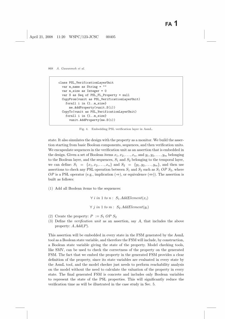
Figure 4 shows the example of the PSL VerificationLayerUnit.CopyFrom() andPSL VerificationLayerUnit.CopyTo() methods. The latter is usually used to con-struct the unit by copying properties from or into other existent units, respectively.
4.4. Modeling layer
This layer is not used in our verification approach since it is intended for VHDLand Verilog flavors of PSL. So we did not consider it in our current embedding.
4.5. Verifying PSL properties
PSL properties are embedded in AsmL as assertions; assertion here means the valid-ity of the property and provides a unique view of the property in every system’s
April 21, 2008 11:20 WSPC/123-JCSC 00405
868 A. Gawanmeh et al.
class PSL_VerificationLayerUnit
var m_name as String = ""
var m_size as Integer = 0
var S as Seq of PSL_FL_Property = null
CopyFrom(vunit as PSL_VerificationLayerUnit)
forall i in {1..m_size}
me.AddProperty(vunit.S(i))
CopyTo(vunit as PSL_VerificationLayerUnit)
forall i in {1..m_size}
vunit.AddProperty(me.S(i))
Fig. 4. Embedding PSL verification layer in AsmL.
state. It also simulates the design with the property as a monitor. We build the asser-tion starting from basic Boolean components, sequences, and then verification units.We encapsulate sequences in the verification unit as an assertion that is embedded inthe design. Given a set of Boolean items x1, x2, . . . , xn, and y1, y2, . . . , ym belongingto the Boolean layer, and the sequences, S1 and S2 belonging to the temporal layer,we can define: S1 = {x1, x2, . . . , xn} and S2 = {y1, y2, . . . , ym}, and then useassertions to check any PSL operation between S1 and S2 such as S1 OP S2, whereOP is a PSL operator (e.g., implication (⇒), or equivalence (⇔)). The assertion isbuilt as follows:
(1) Add all Boolean items to the sequences:
∀ i in 1 to n : S1.AddElement(xi)
∀ j in 1 to m : S2.AddElement(yi)
(2) Create the property: P := S1 OP S2
(3) Define the verification unit as an assertion, say A, that includes the aboveproperty: A.Add(P ).
This assertion will be embedded in every state in the FSM generated by the AsmLtool as a Boolean state variable, and therefore the FSM will include, by construction,a Boolean state variable giving the state of the property. Model checking tools,like SMV, can be used to check the correctness of the property on the generatedFSM. The fact that we embed the property in the generated FSM provides a cleardefinition of the property, since its state variables are evaluated in every state bythe AsmL tool, and the model checker just needs to perform reachability analysison the model without the need to calculate the valuation of the property in everystate. The final generated FSM is concrete and includes only Boolean variablesto represent the state of the PSL properties. This will significantly reduce theverification time as will be illustrated in the case study in Sec. 5.
April 21, 2008 11:20 WSPC/123-JCSC 00405
A Design for Verification Approach Using an Embedding of PSL in AsmL 869
5. Case Study: Modeling and Verification of the PCI-X Bus
5.1. PCI-X bus description
Improvements in processors and peripheral devices have caused conventional PCItechnology to become a bottleneck to performance scalability. The introduction ofthe PCI-X technology22 has provided the necessary bandwidth and bus performanceneeded to avoid the I/O bottleneck, thus achieving optimal system performance.For instance, version 2.0 of PCI-X specifies a 64-bit connection running at speedsof 66, 133, 266, or 533 MHz, resulting in a peak bandwidth of 533, 1066, 2133, or4266 MB/s, respectively.
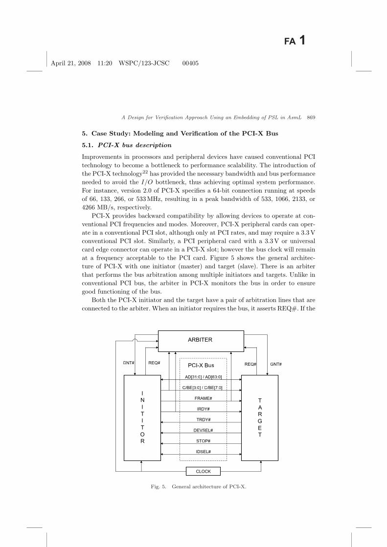
PCI-X provides backward compatibility by allowing devices to operate at con-ventional PCI frequencies and modes. Moreover, PCI-X peripheral cards can oper-ate in a conventional PCI slot, although only at PCI rates, and may require a 3.3 Vconventional PCI slot. Similarly, a PCI peripheral card with a 3.3V or universalcard edge connector can operate in a PCI-X slot; however the bus clock will remainat a frequency acceptable to the PCI card. Figure 5 shows the general architec-ture of PCI-X with one initiator (master) and target (slave). There is an arbiterthat performs the bus arbitration among multiple initiators and targets. Unlike inconventional PCI bus, the arbiter in PCI-X monitors the bus in order to ensuregood functioning of the bus.
Both the PCI-X initiator and the target have a pair of arbitration lines that areconnected to the arbiter. When an initiator requires the bus, it asserts REQ#. If the
CLOCK
AD[31:0] / AD[63:0]
C/BE[3:0] / C/BE[7:0]
FRAME#
IRDY#
TRDY#
DEVSEL#
STOP#
IDSEL#
PCI-X Bus
INITITOR
TARGET
ARBITER
GNT# REQ# GNT#REQ#
Fig. 5. General architecture of PCI-X.

April 21, 2008 11:20 WSPC/123-JCSC 00405
870 A. Gawanmeh et al.
arbiter decides to grant the bus to that initiator, it asserts GNT#. FRAME# andIRDY# are used by the arbiter to decide the granting to an initiator’s request ofthe bus. Unlike PCI, the targets can only insert wait states by delaying the assertionof TRDY#. TRDY# and IRDY# have to be asserted for a valid data transfer. Aninitiator can abort the transaction either before or after the completion of the datatransfer by de-asserting the FRAME# signal. In contrast, a target can terminatea bus transaction by asserting STOP#. If STOP# is asserted without any datatransfer, it means that the target has issued a retry and if STOP# is asserted afterone or more data phases, it means that the target has issued a disconnect. UnlikePCI, the target has also REQ# and GNT# that are connected to the arbiter. Thisfacilitates the split transaction of PCI-X which does not exist in conventional PCI.In split transaction, the initiators and targets switch their roles. Split transactionis very useful if a target cannot continue the current transaction. In this case, thetarget will memorize the transaction and signal a split telling the initiator not toretry IO read. When the data is ready, the target will send the initiator a SplitCompletion containing the data. The addition of PCI-X Split Completion frees upthe bus for other transactions, making PCI-X more efficient than PCI. This notionof split transaction of PCI-X and its high bandwidth capacity makes the PCI-Xbus pretty complex.
5.2. UML modeling of PCI-X bus
From the specification of PCI-X, we identify the core components, i.e., initiators,targets, and arbiters, which will be represented as classes, where specific instances ofthe components are called as objects. In addition to these four components, we alsoadded another component, the Simulation Manager (SimManager), in order to havea notion of updates. Figure 6 shows these five classes, where each has its own datamembers and methods with their access types. It also shows the relationship amongeach class. For instance, the relationship between the arbiter and the initiators isone-to-many (1–*), because there is only one arbiter which is connected to manyinitiators. However, the relationship between the SimManager and arbiter is one-to-one (1–1) as there is only one SimManager and one arbiter in the system.
We modeled different modes and types of operations of PCI-X using sequencediagrams. Sequence diagrams enable us to model the bus in AsmL easily and effi-ciently. Also, they help to extract the properties of the system being modeled, whichcan be used to verify using model checking. In addition, UML modeling helps toclose the gap between informal specification and formal models in AsmL.
In Fig. 7, we show the protocol sequence of a typical Mode 1 transaction ofthe PCI-X using a sequence diagram. Figure 7 is a best case scenario of Mode1 transactions, with one initiator and one target and without any wait states. Inthe first clock cycle, the initiator asserts the REQ# signal to get the control ofthe bus by executing the methods Initiator Req(). The arbiter asserts the GNT#signal to that initiator through Arbiter GNT UPD(). In the third clock cycle, the

April 21, 2008 11:20 WSPC/123-JCSC 00405
A Design for Verification Approach Using an Embedding of PSL in AsmL 871
+A rb ite r()
+A rb it er _G NT _U PD()
+A rb it er _R el ea se ()
+A rb it er _P ar k_ In it ia tor( )
PCIX _A rb it er
+A ct iv e_ In it ia to r : in t
+R EQ : boo l
+G NT : b oo l
+C BE : i nt
+F RAME : b oo l
+I RDY : b oo l
+P CI X_ Bu s( )
+P CI X_ Bu s_ Da ta Ph as e( )
PCIX _B us
+C LK : b oo l
+F RA ME : boo l
+I RDY : b oo l
+T RDY : b oo l
+D EVS EL : b oo l
+S TO P : bo ol
+A D : in t
+C BE : i nt
+I ni ti at or _R eq ()
+I ni ti at or _F RAME _A ss er t( ) +Att ri bu te _P ha se ()
+I ni ti at or _I RDY _A ss er t( )
+I ni ti at or _T er mi na ti on( )
+I ni ti at or _L as tP ha se ()
+I ni ti at or _R el ea se ()
+I ni ti at or _D is co nn ec t( )
+I ni ti at or _A bo rt()
PC IX _Ini ti at or
+R EQ : b oo l
+G NT : b oo l
+F RAME : b oo l
+I RDY : b oo l
+I DS EL : b oo l
+A D : in t
+C BE : i nt
+D EST : i nt
+STO P : bo ol
+T ar ge t( ) +T ar ge t_ DE VSEL _A ss er t( )
+T ar ge t_ T RDY _A sse rt ()
+T ar ge t_ A bor t( )
+T ar ge t_ Te rm in at io n( )
+T ar ge t_ Re sp on se ()
PCIX _T ar ge t
+R EQ : b oo l
+G NT : b oo l
+T RDY : b oo l
+D EVSEL : b oo l
+S TO P : bo ol
+A D : in t
+C BE : i nt
+I D : in t
+T ARGE T_ ST OP : b oo l
+S im Ma na ge r( )
+S im Ma na ge r_ In it ()
+S im Ma na ge r_ CL K_ Up da te ()
Si mM an ag er
+C LK : b oo l
*
1
1
*
*
1
*
1
1
1
1
1
*
1
*
1
1
1
Fig. 6. Class diagram of PCI-X.
address phase takes place and also the FRAME# signal is asserted by the initiatorto signal the start of the transaction using the method Initiator FRAME Assert().In the next clock cycle, the attribute phase takes place, where additional informa-tion included with each transaction is added. In clock cycle N + 4, the DEVSEL#signal is asserted by the target using Target DEVSEL Assert() and in the nextclock cycle, the data phase is started with the assertion of the IRDY# (Initia-tor IRDY Assert()) and TRDY# (Target TRDY Assert()) signals by the initiatorand the target, respectively. Before the last data phase, the FRAME# signal is de-asserted using Initiator Termination() to signal the completion of the data trans-fer, and in the termination phase all the other signals are de-asserted. In order torepresent the clock constraints of the PCI-X transaction, we added an additionaloperator, “@”, to specify at which clock cycle a particular action should occur.
Figure 8 shows the protocol sequence of a typical Mode 2 transaction of PCI-Xusing a sequence diagram. Mode 2 transaction is pretty similar to that in Fig. 7,except that there is an additional delay of one clock cycle (Target Response Phase)and one additional idle clock between any two transactions.
In Fig. 9, we show the transaction sequences of a 16-bit interface of Mode 2transaction. In this transaction, the attribute phase takes two cycles unlike thetransaction types. Other signal activities of this transaction are the same as the

April 21, 2008 11:20 WSPC/123-JCSC 00405
872 A. Gawanmeh et al.
Initiator TargetArbiterPCI-X-Bus
Initiator_Req()@ClkN
Arbiter_GNT_UPD()@clkN+1
AttributePhase()@clkN+3
Target_DEVSEL_Assert()@clkN+4
Initiator_IRDY_Assert()@clkN+5
Initiator_FRAME_Assert()
@clkN+2
Target_TRDY_Assert()@clkN+5
PCIX_Bus_Data_Phase()Initiator_Termination()
@clkN+7(Initiator Termination)
Initator_Disconnect()Initiator_LastPhase()
@clkN+9Target_Termination()
@clkN+9
PCIX_Bus_Data_Phase()
PCIX_Bus_Data_Phase()
PCIX_Bus_Data_Phase()
Fig. 7. Sequence diagram of Mode 1 transaction.
generic Mode 2 transaction. In the following section, we present the AsmL modelingof PCI-X from UML.
5.3. AsmL modeling of PCI-X bus
We use AsmL’s class features to model all the core components of PCI-X. Each ofthese has its own data members (signals) and methods (behavior) in addition to theconstructors. We also use enumeration features (enum) of AsmL to model differentmodes of PCI-X, different types of transaction phases, the state of the system andthe clock.
In addition, we exhaustively use the require and “:=” statements of AsmL inour design approach. require is the precondition statement in AsmL used to checkif a certain condition is satisfied in order to proceed a method, and the operator“:=” represents an update statement used to change the system state. Figure 10shows the AsmL model of the arbiter grant method (Arbiter GNT()). As the nameof the method says it acts as an arbiter for granting the bus to the requestinginitiator. In order to grant the bus to the requested initiator, this method has thefollowing preconditions (require) to be met: (1) there must be at least one initiator

April 21, 2008 11:20 WSPC/123-JCSC 00405
A Design for Verification Approach Using an Embedding of PSL in AsmL 873
Initiator TargetArbiterPCI-X-Bus
Initiator_Req() @clkN
Arbiter_GNT_UPD()
@clkN+1
Attribute_Phase()
@clkN+3
Target_DEVSEL_Assert()
@clkN+5Initiator_IRDY_Assert()
@clkN+5
PCIX_Bus_DataPhase()
Initiator_FRAME_Assert()
@clkN+2
(Address Phase)
Target_TRDY_Assert()@clkN+6
Initiator_Termination()
@clkN+8
Termination PhaseInitiator_Disconnect()
@clkN+10Target_Termination()
@clkN+10
One Idle ClockTo Begin Next
Transaction
Target_Response()
@clkN+4
PCIX_Bus_DataPhase()
PCIX_Bus_DataPhase()
PCIX_Bus_DataPhase()
Fig. 8. Sequence diagram of Mode 2 transaction.
requesting the bus, and that initiator has not been granted the bus at the timeof the request; (2) the clock is on the rising edge; and (3) the mode can be eitherMode 1 or Mode 2. If these preconditions are met, the arbiter updates the GNT#signal.
In Fig. 11, we show how a target can signal its readiness using TRDY# signal.We call this method as Target TRDY Assert(). The preconditions are the following:TRDY# is false, FRAME# and DEVSEL# are true, CLK is CLK UP, Phase isDATA PHASE FIRST, and the AD of the Bus should be the ID of the target. Ifthe preconditions are true, then TRDY# will be asserted.
Figure 12 shows the initiator termination method (Initiator Termination). Thismethod basically signals the end of a transaction if BYTECOUNT is less than 2.BYTECOUNT indicates the number of bytes of data transfer in a transaction. Thissignaling is done by de-asserting the FRAME# signal and updating the transac-tion phase to the initiator termination phase (INI TER PHASE). This method hasspecific preconditions that need to be true so that it can terminate the transac-tions. The preconditions (require) are the following: initiator’s REQ#, GNT#,

April 21, 2008 11:20 WSPC/123-JCSC 00405
874 A. Gawanmeh et al.
In it ia to r Ta rg et Ar bi te r PC I-X- Bu s
In it ia tor_R eq( ) @ cl kN
Ar bi ter_ GN T_ UPD( )
@c lk N+ 1
At tr ib ut e_ Ph as e( )
@c lk N+ 3
Ta rg et _D EVSE L_ As se rt()
@c lk N+ 6 In it ia to r_ I RDY _A ss er t( )
@c lk N+ 6
PC IX _B us _D at aP ha se ()
In it ia to r_ FRAM E_ As se rt ()
@c lk N+ 2
(A dd re ss Ph as e)
Ta rg et _T RDY _A ss er t( )
@c lk N+ 8
In it ia to r_ Te rmin at io n( )
@c lk N+ 9
Te rmin at io n P ha se In it ia to r_ Di sc o nne ct ()
@c lk N+ 11 Ta rg et _T er mi na ti on( )
@c lk N+ 11
On e I dl e C lo ck
To Be gi n N ex t
Tr an sa ct io n
Ta rg et _R es po ns e( )
@c lk N+ 5
PCIX _B us _D at aP ha se ()
PCIX _B us _D at aP ha se ()
PCIX _B us _D at aP ha se ()
At tr ib ut eP ha se ()
@c lk N+ 4
Fig. 9. Sequence diagram of Mode 2 transaction (16 bit).
public Arbiter_GNT()
require (exists x in Initiators where x.REQ = true and
x.GNT = false) and me.GNT = false and Smanager.CLK = CLK_UP
and (Mode = MODE_1 or Mode = MODE_2)
me.Active_Initiator := min y | y in Initiators_Range where
(Initiators(y).REQ = true)
me.GNT := true
Initiators(Active_Initiator).GNT := true
Fig. 10. Arbiter grant AsmL method.
FRAME#, IRDY#, DEVSEL#, TRDY# are asserted, BYTECOUNT is lessthan 2, and the clock is on the rising edge. If all the above preconditions are true, thismethod updates the FRAME# signal to false and the phase to INI TER PHASE.

April 21, 2008 11:20 WSPC/123-JCSC 00405
A Design for Verification Approach Using an Embedding of PSL in AsmL 875
public Target_TRDY_Assert()
require me.TRDY = false and Bus.FRAME = true and
Bus.AD = me.ID and Bus.DEVSEL = true and
Smanager.CLK = CLK_UP and Phase = DATA_PHASE_FIRST
me.TRDY := true
me.AD := Bus.AD
Bus.TRDY := true
Phase := DATA_PHASE
Fig. 11. Target assert AsmL method.
public Initiator_Termination()
require me.GNT = true and me.REQ = true and me.FRAME = true and
me.IRDY = true and Bus.TRDY = true and Bus.DEVSEL = true
and BYTECOUNT < 2 and me.STOP = false and
Smanager.CLK = CLK_UP
me.FRAME := false
Bus.FRAME := false
Phase := INR_TER_PHASE
Fig. 12. Initiator termination AsmL method.
After this FRAME# signal de-assertion, the initiator’s last phase method (Initia-tor LastPhase()) is invoked.
5.4. PCI-X bus PSL properties
Properties are embedded in every state in the FSM generated by the Asmlt and isrepresented by two Boolean state variables Peval and Pval. Peval represents whethera property can be evaluated or not and Pval denotes the state of the property inthe current state. A violated property is detected Pval = false.
We define various properties of the PCI-X bus in PSL. The properties areobtained from the sequence diagrams and the informal specification. Some of theproperties that we show are generic to any bus protocols and others are specificto PCI-X. The properties range between common behaviors for any bus standardto specific properties for the PCI-X high-speed bus standard. We defined 10 PSLproperties and then modeled them in AsmL. The description and AsmL code forthese properties are shown in Appendix A.
5.5. Experimental results
Table 1 details the results of model checking the aforementioned 10 properties(see Appendix A) on a PCI-X model with five initiators and five targets. Theinformal descriptions and formal definition of these properties in AsmL are given

April 21, 2008 11:20 WSPC/123-JCSC 00405
876 A. Gawanmeh et al.
Table 1. Model checking results.
Property CPU time (s) States Transitions
P1 385.24 2169 3250P2 194.23 1800 2563P3 150.52 1578 2156P4 130.45 1489 2096P5 156.35 1478 2265P6 173.50 1925 2439P7 174.47 2013 2698P8 178.42 1873 2359P9 256.63 2192 2980P10 143.52 1356 1923
in Appendix A. In Table 1, we show the CPU time, number of states and transitionsfor the PCI-X model with the various properties defined. The experiments wereperformed on a Pentium IV processor (2.4 GHz) with 768MB of memory. Eventhough the CPU time to verify the properties is relatively short, we have to considerthe time spent to write the properties and to learn the tool. Using the approachproposed in Ref. 7, it is also possible to model check a SystemC design of thePCI-X, but the state space explosion will be worse considering the complexity ofthe SystemC simulation semantics and the OO nature of the language. The resultsachieved here are superior to the results obtained in Ref. 7 in terms of machineexecution time, and taking into consideration that the time here represents boththe generation of the FSM and the evaluation of the property, which combines thetime for the two separated steps in the other approach: generating the FSM andmodel checking using an external model checker. We also presented a high levelmodel for the PCI-X bus and verified several nontrivial properties illustrating theefficiency of our approach.
Comparing the results we obtained in our approach to the previous works inRefs. 3, 21, 24, 27, and 29, this work considers designing and verifying the latesthigh-speed bus standard (PCI-X) including its very complex transaction rules. Inaddition, the modeling of the PCI-X at the transaction level and verifying variousproperties using model checking approach is made feasible using our methodology.
6. Conclusion
The verification of systems is the bottleneck in the design cycle because systemscombine various hybrid components and behaviors. Classical functional verificationis consuming an inordinate amount of the design cycle time. This paper presents anintegration of a design for verification approach into the high-level design processand enables model checking for large systems based on the embedding of PSL inAsmL. Starting from an informal specification of the system, we derive first an UMLdescription in terms of class and sequence diagrams to validate high level behavior.From the UML design, we derive an AsmL model of the system refining more detailsof its implementation, which we formally verify against a set of PSL properties. Theverification of PSL properties is performed by including the PSL properties in the

April 21, 2008 11:20 WSPC/123-JCSC 00405
A Design for Verification Approach Using an Embedding of PSL in AsmL 877
AsmL design and generating an FSM of the model that contains the embeddedPSL properties. Using Asmlt, we perform state exploration which gives the notionof model checking. For embedding PSL in AsmL, we adopted deep embedding inAsmL of the three hierarchical layers: Boolean, temporal, and verification of PSL.An AsmL model combining both the reduced design and the PSL property is inputto the AsmL tool, which compiles it into C#, and generates its FSM.
We illustrated this approach through a case study of the PCI-X bus, on which weverified several PSL sample properties. The PCI-X bus is an industrial size design.The UML representation of PCI-X was developed in terms of class diagrams andsequence diagrams. Then, an AsmL model was designed from the UML representa-tion. We then integrated various PSL properties into the AsmL model and appliedmodel checking for the system. We achieved promising results by verifying sev-eral properties on the bus model. We intend to provide a mechanized refinementapproach in future, by generating SystemC model from the AsmL model. It is alsopossible to formalize PSL into ASM (not AsmL) in order to provide rigorous def-initions for PSL semantics. We also propose to explore the possibility of applyingthis approach on other system modeling languages like SystemVerilog.25
Appendix A: PSL Properties for PCI-X Bus in AsmL
The first property P1, is a common behavior of any bus standard. It states that ifan initiator is requesting the bus (!Initiator.REQ == true), it will eventually begranted (!Initiator.GNT == true). This also makes sure the fact that no initiatorwill be using the bus indefinitely. It is to be noted that all signals of PCI-X areactive-low.
Property P1:
forall Initiator in {Initiator0, ..., Initiator4}
if(!Initiator.REQ == true) then
eventually (!Initiator.GNT == true)
Property P2 is about the termination of a PCI-X transaction be it Mode 1 orMode 2. It means that if an initiator is terminating the bus by asserting the STOPsignal, then eventually the bus will be released by de-asserting the FRAME signaland targets will be released by de-asserting TRDY and DEVSEL.
Property P2:
forall Initiator in {Initiator0, ..., Initiator4}
if((!Initiator.STOP == true) and
(!Initiator.GNT == true)) then
eventually {(!Bus.FRAME == false) and
forall Target in {Target0, ..., Target4}
(!Target.TRDY == false) and
(!Target.DEVSEL == false)}

April 21, 2008 11:20 WSPC/123-JCSC 00405
878 A. Gawanmeh et al.
Property P3 is for the assertion of FRAME signals. This property is importantfor the start of the transaction. If an initiator is granted to the bus, then in thenext clock cycle the FRAME signal has to be asserted.
Property P3:
forall Initiator in {Initiator0, ..., Initiator4}
if(!Initiator.GNT == true) then
next[0] (!Initiator.FRAME == true)
Property P4 is to check the phase (ADDR PHASE, ATTR PHASE,
IDLE PHASE) of the transaction. If the initiator FRAME signal is asserted, thenin the next clock cycle, the phase of the transaction will be the attribute phase(ATTR PHASE).
Property P4:
forall Initiator in {Initiator0, ..., Initiator4}
if(!Initiator.FRAME == true) then
next[0] (Transaction_Phase == ATTR_PHASE)
Property P5 is regarding the arbitration of the bus. If an initiator is selected bythe arbiter, then it will be able to get access to the bus by setting !Bus.FRAME.Then, its destination target will be activated by setting its !Target.TRDY and theinitiator will release the bus once !Initiator.GNT is set to false.
Property P5:
forall Initiator in {Initiator0, ..., Initiator4}
forall Target in {Target0, ..., Target4}
if((!Target.GNT == true) and
(!Initiator.DEST == Target.ID)) then
eventually {(!Bus.FRAME == true) and
(!Initiator.TRDY == true) and
(!Target[ID].TRDY == true) and
(!Target.GNT == false)}
Property P6 is to check the response of a target when it has been selected asdestination. This property is specific for Mode 1 transaction. The property saysthat if the transaction mode is MODE 1 and the initiator’s FRAME is asserted,then eventually the IRDY and TRDY of the initiator and target, respectively, willbe asserted.
Property P6:
forall Initiator in {Initiator0, ..., Initiator4}
forall Target in {Target0, ..., Target4}
if((!Initiator.FRAME == true) and

April 21, 2008 11:20 WSPC/123-JCSC 00405
A Design for Verification Approach Using an Embedding of PSL in AsmL 879
(Transaction_Mode == MODE_1)) then
eventually {(!Initiator.IRDY == true) and
(!Target.TRDY == true)}
Property P7 is related to the Mode 2 transaction. If FRAME is assertedand transaction is Mode 2, then eventually IRDY and DEVSEL will be assertedtogether.
Property P7:
forall Initiator in {Initiator0, ..., Initiator4}
forall Target in {Target0, ..., Target4}
if(!Initiator.FRAME == true) and
(Transaction_Mode == MODE_2) then
eventually {(!Initiator.IRDY == true) and
(!Target.TRDY == true)}
Property P8 is about the target response property of Mode 2 transaction. IfFRAME, IRDY, and DEVSEL are asserted and the transaction is Mode 2, then inthe next clock cycle, TRDY will be asserted.
Property P8:
forall Initiator in {Initiator0, ..., Initiator4}
forall Target in {Target0, ..., Target4}
if(!Initiator.FRAME == true) and
(!Initiator.IRDY == true) and
(!Target.DEVSEL == true) and
(Transaction_Mode == MODE_2) then
next (!Target.TRDY == true)
Property P9 checks the idle phase of Mode 2 transaction after a transactionhas completed. It says that if IRDY, STOP, DEVSEL, and TRDY are de-asserted,then in the next clock cycle, the phase of the transaction will be idle. In otherwords, the bus will be idle.
Property P9:
forall Initiator in {Initiator0, ..., Initiator4}
forall Target in {Target0, ..., Target4}
if((!Initiator.IRDY == false) and
(!Initiator.STOP == false) and
(!Target.DEVSEL == false) and
(!Target.TRDY == false) and
(Transaction_Mode == MODE_2)) then
next (Transaction_Phase == IDLE_PHASE)

April 21, 2008 11:20 WSPC/123-JCSC 00405
880 A. Gawanmeh et al.
Property P10 is about the initiation of split transaction. In split transaction,the target can request for the bus (!Target.REQ == true) and it can be eventuallygranted (!Target.GNT == true).
Property P10:
forall Target in {Target0, ..., Target4}
if(!Target.REQ == true) and
(Transaction_Mode == SPLIT) then
eventually (!Target.GNT == true)
References
1. E. Borger and R. Stark, Abstract State Machines: A Method for High-Level SystemDesign and Analysis (Springer-Verlag, 2003).
2. K. Claessen and J. Martensson, An operational semantics for weak PSL, FormalMethods in Computer-Aided Design, LNCS 3312 (Springer-Verlag, 2004), pp. 337–351.
3. K. H. Chang, Y. C. Su, W. T. Tu, Y. J. Yeh and S. Y. Kuo, A PCI-X verificationenvironment using C and Verilog, VLSI Design/CAD Symp., Taiwan (2003).
4. M. Chong, A PCI express to PCI-X bridge optimized for performance and area,Master’s thesis, Department of Electrical Engineering and Computer Science, Mas-sachussets Institute of Technology (2004).
5. M. Dwyer, J. Hatcliff, R. Joehanes, S. Laubach, C. Pasareanu, R. W. Visser andH. Zheng, Tool-supported program abstraction for finite-state verification, Int. Conf.Software Engineering, Toronto, Canada (2001), pp. 177–187.
6. A. Gawanmeh, A. Habibi and S. Tahar, Enabling SystemC verification using abstractstate machines, Languages for Formal Specification and Verification, Forum on Spec-ification and Design Languages, September 2004.
7. A. Gawanmeh, A. Habibi and S. Tahar, Embedding and verification of PSL usingASM, IEEE Int. Workshop on System-on-Chip, December 2006, pp. 125–130.
8. A. Gawanmeh, S. Tahar and K. Winter, Formal verification of ASMs using MDGs,to appear in J. Syst. Architecture (2008).
9. W. Grieskamp, Y. Gurevich, W. Schulte and M. Veanes, Generating finite statemachines from abstract state machines, Software Eng. Notes 27 (2002) 112–122.
10. D. Grobe and R. Drechsler, Checkers for SystemC designs, 2nd ACM and IEEE Int.Conf. Formal Methods and Models for Codesign, San Diego, USA (2004), pp. 171–178.
11. M. Gordon, J. Hurd and K. Slind, Executing the formal semantics of the accelleraproperty specification language by mechanised theorem proving, Correct HardwareDesign and Verification Methods, LNCS 2860 (Springer-Verlag, 2003), pp. 200–215.
12. M. Gordon and T. Melham, Introduction to HOL: A Theorem Proving Environmentfor Higher-Order Logic (Cambridge University Press, Cambridge, UK, 1993).
13. M. Gordon, Validating the PSL/sugar semantics using automated reasoning, FormalAspects Comput. 15 (2003) 406–421.
14. Y. Gurevich, Evolving algebras 1995: Lipari Guide, Specification and Validation Meth-ods (Oxford University Press, 1995).
15. Y. Gurevich, B. Rossman and W. Schulte, Semantic essence of AsmL, TechnicalReport, Microsoft Research, MSR-TR-2004-27, March 2004.
16. A. Habibi, A framework for system level verification: The SystemC case, PhD thesis,Concordia University, Montreal, Canada (2005).

April 21, 2008 11:20 WSPC/123-JCSC 00405
A Design for Verification Approach Using an Embedding of PSL in AsmL 881
17. A. Habibi and S. Tahar, On the transformation of SystemC to AsmL using abstractinterpretation, Electron. Notes Theor. Comput. Sci. 131 (2005) 39–49.
18. J. Huggins, Abstract state machines website, http://www.eecs.umich.edu/gasm(2003).
19. M. L. McMillan, Symbolic Model Checking (Kluwer Academic Publishers, 1993).20. H. Moinudeen, A. Habibi and S. Tahar, Design for verification of the PCI-X bus, IEEE
Int. Conf. Formal Methods in Computer-Aided Design (IEEE Computer Society Press,2006), pp. 187–188.
21. K. Oumalou, A. Habibi and S. Tahar, Design for verification of a PCI bus in SystemC,Symp. System-on-Chip, IEEE Computer Society Press, November 2004, pp. 201–204.
22. PCI Special Interest Group, www.pcisig.com (2005).23. Accellera Property Specification Language Reference Manual, Version 1.01, http://
www.accellera.org (2004).24. K. Shimizu, D. Dill and A. Hu, Monitor-based formal specification of PCI, For-
mal Methods in Computer-Aided Design, LNCS 1954 (Springer–Verlag, 2000),pp. 335–353.
25. SystemVerilog, http://www.systemverilog.org (2004).26. C. Wallace, The semantics of the C++ programming language, Specification and
Validation Methods, Oxford University Press (1995), pp. 131–164.27. R. Wang and Z. Wen, A verification environment for PCI-X BFMs in VERA, Technical
report, Synopsys Inc. (2002).28. K. Winter, Model checking abstract state machines, PhD thesis, Technical University
of Berlin, Germany (2001).29. C. C. Yu, K. Chang, Y. Yeh and S. Kuo, System level assertion-based verification
environment for PCI/PCI-X and PCI-express, VLSI Design/CAD Symp., Taiwan(2004).

April 21, 2008 11:20 WSPC/123-JCSC 00405