A dedicated powder diffraction beamline at the Advanced ... · readout linear variable differential...
7
A dedicated powder diffraction beamline at the Advanced Photon Source: Commissioning and early operational results Jun Wang, a Brian H. Toby, Peter L. Lee, Lynn Ribaud, Sytle M. Antao, Charles Kurtz, Mohan Ramanathan, Robert B. Von Dreele, and Mark A. Beno Advanced Photon Source, Argonne National Laboratory, Argonne, Illinois 60439, USA Received 11 June 2008; accepted 21 July 2008; published online 22 August 2008 A new dedicated high-resolution high-throughput powder diffraction beamline has been built, fully commissioned, and opened to general users at the Advanced Photon Source. The optical design and commissioning results are presented. Beamline performance was examined using a mixture of the NIST Si and Al 2 O 3 standard reference materials, as well as the LaB6 line-shape standard. Instrumental resolution as high as 1.7 10 -4 Q / Q was observed. © 2008 American Institute of Physics. DOI: 10.1063/1.2969260 I. INTRODUCTION Many of the most interesting materials being studied to- day are not available in single-crystal form during the critical period following the initial discovery, if ever. It is precisely during this initial phase that structural information is most critically needed. High-resolution powder diffraction thus provides a key research tool for determining the structure, for following the structural changes as a function of temperature, voltage, field, etc., and for defining future synthetic ap- proaches to enhance desired materials properties, which may include conductivity, thermal expansion, biological activity, or chemical activity. 1–6 Increasingly complex chemistry and physics of modern materials demand that the structural infor- mation be obtained with high precision. The increased num- ber of applications for powder diffraction crystallography de- mands these data be available in a routine fashion. A dedicated high-resolution, high-throughput powder diffraction beamline, 11BM, was proposed, constructed, and commissioned at the Advanced Photon Source APS at Ar- gonne National Laboratory to facilitate high-resolution crys- tallographic structure determination from powder diffraction of complex polycrystalline materials via a high-throughput mail-in service model. This beamline will support a wide range of user interests, from pharmaceuticals through tradi- tional materials science to questions in engineering, cataly- sis, chemistry, geosciences, physics, and electronics. II. BEAMLINE OPTICS Beamline 11BM is built on a bending magnet source operating at an electron energy of 7 GeV with a critical pho- ton energy of 19.5 keV. This beamline is designed to operate in the energy range of 5–40 keV and therefore can cover the K absorption edge for elements from Ti to La, and L absorp- tion edges for elements above Cs for resonant scattering studies. A schematic layout of the beamline is shown in Fig. 1.A 1-m-long mirror is located 26.0 m from the bending magnet source. It collimates beam vertically to minimize the energy spread of the monochromator and to reduce harmonics con- tamination. The mirror has one 50-mm-wide stripe coated in Pt and another 50 mm uncoated Si stripe. At a 2 mrad inci- dent angle, the Pt-coated stripe has a cutoff energy at 40.5 keV, and the Si region at 15.5 keV. The mirror is water cooled, with liquid gallium/indium as the heat transfer me- dium, and is able to translate between the Pt stripe and the uncoated region of the Si to choose a different energy. The mirror acceptance is 50 mm horizontal about 1.9 mrad and 2 mm maximum vertical defined by upstream white beam slits located 23.4 m from the source. A manual mechanical bending mechanism allows the mirror to be bent cylindri- cally from a nearly flat profile to a curvature with a radius of approximately 26 km. Following the collimating mirror, the x-ray beam is monochromated by a 20 mm fixed-exit double-crystal Si 111 monochromator positioned 27.6 m from the source. The first crystal is flat and water cooled, and the second crystal is sagittally bent to focus the beam horizontally. The sagittal focusing assembly was purchased from Oxford- Danfysik with the design licensed to Oxford-Danfysik from the ESRF. There is a gear reducer 28:1 and a positional readout linear variable differential transformer LVDT for each bender motor. The gear reducer increases the accuracy of the motion by a factor of 28 and enhances the torque necessary for high-energy operation; for example, the bend- ing radius is 1.6 m at 30 keV. The LVDT acts as an encoder and allows us to move to positional values indicated by the LVDT readouts. This eliminates or significantly reduces any backlash problems. The orientation of the second crystal may be adjusted with four degrees of freedom: a slide positions the second crystal relative to the first to maintain a constant beam dis- placement; a yaw control allows rotation around the crystal surface normal, which is crucial for compensating the twist of the sagittal crystal; the pitch control, which has both a motorized coarse adjustment and a piezoelectric fine adjust- a Author to whom correspondence should be addressed. Electronic mail: [email protected]. REVIEW OF SCIENTIFIC INSTRUMENTS 79, 085105 2008 0034-6748/2008/798/085105/7/$23.00 © 2008 American Institute of Physics 79, 085105-1 Downloaded 19 Sep 2008 to 164.54.111.19. Redistribution subject to AIP license or copyright; see http://rsi.aip.org/rsi/copyright.jsp
Transcript of A dedicated powder diffraction beamline at the Advanced ... · readout linear variable differential...
A dedicated powder diffraction beamline at the Advanced Photon Source:Commissioning and early operational results
Jun Wang,a! Brian H. Toby, Peter L. Lee, Lynn Ribaud, Sytle M. Antao, Charles Kurtz,Mohan Ramanathan, Robert B. Von Dreele, and Mark A. BenoAdvanced Photon Source, Argonne National Laboratory, Argonne, Illinois 60439, USA
!Received 11 June 2008; accepted 21 July 2008; published online 22 August 2008"
A new dedicated high-resolution high-throughput powder diffraction beamline has been built, fullycommissioned, and opened to general users at the Advanced Photon Source. The optical design andcommissioning results are presented. Beamline performance was examined using a mixture of theNIST Si and Al2O3 standard reference materials, as well as the LaB6 line-shape standard.Instrumental resolution as high as 1.7!10!4 !"Q /Q" was observed. © 2008 American Institute ofPhysics. #DOI: 10.1063/1.2969260$
I. INTRODUCTION
Many of the most interesting materials being studied to-day are not available in single-crystal form during the criticalperiod following the initial discovery, if ever. It is preciselyduring this initial phase that structural information is mostcritically needed. High-resolution powder diffraction thusprovides a key research tool for determining the structure, forfollowing the structural changes as a function of temperature,voltage, field, etc., and for defining future synthetic ap-proaches to enhance desired materials properties, which mayinclude conductivity, thermal expansion, biological activity,or chemical activity.1–6 Increasingly complex chemistry andphysics of modern materials demand that the structural infor-mation be obtained with high precision. The increased num-ber of applications for powder diffraction crystallography de-mands these data be available in a routine fashion.
A dedicated high-resolution, high-throughput powderdiffraction beamline, 11BM, was proposed, constructed, andcommissioned at the Advanced Photon Source !APS" at Ar-gonne National Laboratory to facilitate high-resolution crys-tallographic structure determination from powder diffractionof complex polycrystalline materials via a high-throughputmail-in service model. This beamline will support a widerange of user interests, from pharmaceuticals through tradi-tional materials science to questions in engineering, cataly-sis, chemistry, geosciences, physics, and electronics.
II. BEAMLINE OPTICS
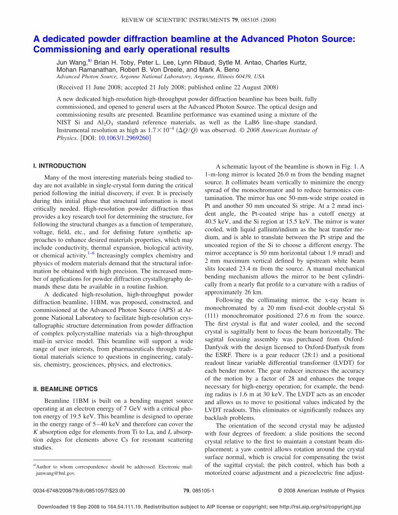
Beamline 11BM is built on a bending magnet sourceoperating at an electron energy of 7 GeV with a critical pho-ton energy of 19.5 keV. This beamline is designed to operatein the energy range of 5–40 keV and therefore can cover theK absorption edge for elements from Ti to La, and L absorp-tion edges for elements above Cs for resonant scatteringstudies.
A schematic layout of the beamline is shown in Fig. 1. A1-m-long mirror is located 26.0 m from the bending magnetsource. It collimates beam vertically to minimize the energyspread of the monochromator and to reduce harmonics con-tamination. The mirror has one 50-mm-wide stripe coated inPt and another 50 mm uncoated Si stripe. At a 2 mrad inci-dent angle, the Pt-coated stripe has a cutoff energy at40.5 keV, and the Si region at 15.5 keV. The mirror is watercooled, with liquid gallium/indium as the heat transfer me-dium, and is able to translate between the Pt stripe and theuncoated region of the Si to choose a different energy. Themirror acceptance is 50 mm horizontal !about 1.9 mrad" and2 mm maximum vertical defined by upstream white beamslits located 23.4 m from the source. A manual mechanicalbending mechanism allows the mirror to be bent cylindri-cally from a nearly flat profile to a curvature with a radius ofapproximately 26 km.
Following the collimating mirror, the x-ray beam ismonochromated by a 20 mm fixed-exit double-crystal Si!111" monochromator positioned 27.6 m from the source.The first crystal is flat and water cooled, and the secondcrystal is sagittally bent to focus the beam horizontally. Thesagittal focusing assembly was purchased from Oxford-Danfysik with the design licensed to Oxford-Danfysik fromthe ESRF. There is a gear reducer !28:1" and a positionalreadout linear variable differential transformer !LVDT" foreach bender motor. The gear reducer increases the accuracyof the motion by a factor of 28 and enhances the torquenecessary for high-energy operation; for example, the bend-ing radius is 1.6 m at 30 keV. The LVDT acts as an encoderand allows us to move to positional values indicated by theLVDT readouts. This eliminates or significantly reduces anybacklash problems.
The orientation of the second crystal may be adjustedwith four degrees of freedom: a slide positions the secondcrystal relative to the first to maintain a constant beam dis-placement; a yaw control allows rotation around the crystalsurface normal, which is crucial for compensating the twistof the sagittal crystal; the pitch control, which has both amotorized coarse adjustment and a piezoelectric fine adjust-
a"Author to whom correspondence should be addressed. Electronic mail:[email protected].
REVIEW OF SCIENTIFIC INSTRUMENTS 79, 085105 !2008"
0034-6748/2008/79"8!/085105/7/$23.00 © 2008 American Institute of Physics79, 085105-1
Downloaded 19 Sep 2008 to 164.54.111.19. Redistribution subject to AIP license or copyright; see http://rsi.aip.org/rsi/copyright.jsp

ment, allows relative adjustment of the second crystal’sBragg angle with respect to the first; and a roll control tiltsthe crystal around the incident beam. For the purpose ofequipment protection, thermocouples are placed on the firstcrystal, the pedestal supporting the second crystal, and mostof the control motors.
A second uncooled mirror is situated downstream!29.9 m from the source" to focus the beam vertically inorder to obtain high intensity. The dimensions and coatingspecifications of the second mirror replicate the first mirror.The bending radius can be adjusted manually to focus beamat the sample or detector position, which is about 50 m fromthe source.
To minimize the vertical divergence of the beam, theoptical components are positioned to provide close to a 1:1demagnification ratio for vertical focusing. Although 3:1 isthe optimal demagnification ratio for sagittal focusing to ul-timately satisfy the Bragg condition of the incident beamwith horizontal divergence,7 the investigation of the effect ofthe sagittal focusing on vertical divergence by ray tracingshows that the 3:1 ratio causes asymmetric and broadeneddistribution of the beam vertical divergence.8 Since the high-est resolution for powder diffraction is a driving goal for thisbeamline, the 1:1 demagnification ratio was chosen for thesagittal focusing to provide a symmetric and narrow verticaldivergence distribution at the cost of a loss of intensity at ahigher energy.
III. DIFFRACTOMETER
A Huber two-circle diffractometer is composed of twoheavy-duty high-precision rotary tables !serving as 2# and #angles, respectively", each with a Heidenhain encoder that isaligned coaxially. The axis of rotation is horizontal. The highangular accuracy !3!10!4° " and high precision !$10!5° "allow the diffraction patterns’ peak positions to be accurateand reproducible. The diffractometer, the final beamlineguard slits, and the ion chamber are mounted on a locallydesigned table that has motorized horizontal and verticalmovements and manual rotation adjustability. With these mo-tions the diffractometer axis can be centered and made per-pendicular to the x-ray beam. A Newport optical table top isalso attached on the diffractometer table to provide an areaon which to mount the robotic sample changer, sample envi-ronmental devices, and other accessories. A sample stagewith a high-speed sample spinner and three-axis translationsallows alignment of the spinner axis to the diffractometer
and transverse centering of the sample along the diffracto-meter axis. We have found that a 90 Hz spinning rate opti-mizes sample stability while offering reasonable powder av-eraging for our measurements, which may have count timesas short as 0.01 s.
The multianalyzer/detector system is unique to this in-strument. A brief description follows; a more comprehensivedescription will be published separately.9 To achieve highangular resolution and data collection efficiently, 12 Si !111"crystal analyzer-detector systems are mounted on the diffrac-tometer 2# arm #Fig. 2!a"$. Each analyzer is spaced nomi-nally 2° apart, so a 2° scan provides measurement of a 24°2# range. Each analyzer has an associated LaCl3 !Cyberstar"scintillation detector. The multianalyzer/detector system iscapable of adjusting each analyzer crystal’s orientation ontwo axes. Each crystal’s setting angle !#" has both a coarse!mechanical" and a fine !piezodriven flexure" adjustment,which are computer controlled. The multianalyzer/detectorscheme reduces greatly the data collection time, improves
FIG. 1. Schematic layout of 11BM beamline optics.
FIG. 2. !Color" Pictures of the 11BM !a" 12 analyzer/detector system and!b" robotic sample exchanger.
085105-2 Wang et al. Rev. Sci. Instrum. 79, 085105 "2008!
Downloaded 19 Sep 2008 to 164.54.111.19. Redistribution subject to AIP license or copyright; see http://rsi.aip.org/rsi/copyright.jsp

data reliability by offering redundancy to confirm that mea-surements are internally consistent, and facilitates time-resolved experiments at high resolution. The detector moduleis also designed to prevent cross talk between the analyzer-detector systems. Two parallel slit sets, one before and oneafter each analyzer crystal, collimate and separate the dif-fracted x rays for each analyzer and its associated scintilla-tion detector.
An experimental physics and industrial control system!EPICS"-based beamline control system has been adapted toallow continuous measurements as the 2# angle is scanned,thus eliminating motor repositioning overhead. The 2# posi-tions and the integrated counts from the detector are writtento VME memory by the scaler card. The VME memory isread by the instrument when the scan is finished. This allowsthe entire high-resolution powder diffraction pattern to berecorded in times as short as a few minutes, although a moretypical data collection time is 1 h.
Another unique feature is the robotic sample exchanger.In order to achieve maximum efficiency and effectiveness,an automatic sample-exchange system has been built andintegrated into the diffraction system. This system, shown inFig. 2!b", exploits the high-throughput capability of thisbeamline. The locally designed fingers and interface hard-ware allow the commercial robot to mount, exchange, anddismount samples. The sample capacity of 120 samples canbe expanded as needed. Integral to the design is an EPICScontrol module, which allows the robot to be interfaced as astandard beamline peripheral device, as well as a safety sys-tem that inhibits robotic operation where an operator couldbe endangered by the robot’s rapid motion. High-throughputdata collection is implemented using a combination of web-based database interface and Python instrument controlscripts, which will be described elsewhere.10
An Oxford Cryostreams Cryostream 700+ device allowsautomated temperature control from 80 to 500 K to be inte-grated with robotic operation. Additional sample environ-mental control systems will be added at a later time.
IV. COMMISSIONING RESULTS
The evaluation of beamline performance is based mainlyon two criteria: the instrument resolution function !IRF",which summarizes the instrumental line profile as a functionof diffraction angle 2#, and the x-ray photon flux and focalsize of the incident beam on the sample. In this section wepresent commissioning results from this beamline, with em-phasis on diffractometer system performance.
A. Flux and focusing performance
The measured photon flux at 30 keV is 3!1011 photons /s at the sample position with 100 mA cur-rent. This compares well with the design value of 5.6!1011, which includes the effects of mirror acceptance inboth vertical and horizontal directions, reflectivities of bothmirrors, and a 0.012% bandwidth of the Si !111" monochro-mator. The measured rocking curve of the monochromator at30 keV is shown in Fig. 3!a". The rocking curve width of4.5 arc sec, observed with the sagittal crystal fully focused,
compares well with the calculated value of 2.7 arc sec at thisenergy for a pair of perfectly flat crystals according to x-rayoriented programs !XOP".11 The broadening of the rockingcurve width could be caused by the heat load on the firstcrystal, and the twist and strain from the sagittal crystal. Theloss of the measured flux is consistent with the wider rockingcurve width and therefore can be attributed to imperfectionsin the monochromator crystals.
Figure 4 shows focused horizontal and vertical beamprofiles at the sample position measured by the slit scan. Thefull width at half maximum !FWHM" of the horizontal focalsize is 360 %m. This is compared to the theoretical value of242 %m. The reason for the discrepancy may be due to theribbed sagittal crystal design. The rib width causes the broad-ening of the focal size in the horizontal but necessarily re-duces the anticlastic bending effect that would otherwise sig-nificantly degrade diffraction resolution. The vertical profileis asymmetric and has a slow falloff at the lower side result-ing from a tail on the bottom of the beam that is inherent tosagittal focusing. The FWHM of the vertical profile of thehot spot is about 170 %m, which is in very good agreement
FIG. 3. Rocking curve widths at 30 keV: !a" Si !111" monochromotor crys-tal and !b" Si !111" analyzer crystal.
085105-3 APS powder diffraction beamline Rev. Sci. Instrum. 79, 085105 "2008!
Downloaded 19 Sep 2008 to 164.54.111.19. Redistribution subject to AIP license or copyright; see http://rsi.aip.org/rsi/copyright.jsp

with its calculated value when considering the source verti-cal size, the mirrors’ slope errors, and the focal ratio. In realsample experiments, the vertical beam focal size can be ad-justed to match the sample size. The ability to focus thebeam finely is very advantageous when the material beingstudied is available only in microgram quantities, for ex-ample, the material synthesized at high pressure.
B. Analyzer system performance
The rocking curve widths of all 12 analyzers were mea-sured with an attenuated directed beam, as shown in Fig.3!b". These measurements are repeated routinely to check thediffractometer performance. Initially the independent tilt ad-justment was performed to optimize each analyzer, so allanalyzers could have nearly identical shape and width for therocking curve. This allows the data from all 12 detectors tobe treated as equivalent, allowing the measurements to bemerged and simplifying data analysis. The slight differencein reflectivity shown in Fig. 3!b" is most likely due to thedifferent responses from the detectors and electronics. The
measured rocking curve is symmetric, and the FWHM of therocking curve is 0.005°, which is very close to the expectedvalue.
C. IRF
The analyzer rocking curve width could be viewed as theinstrument resolution !IRF" at zero 2#. The IRF is measuredby observing diffraction peak widths as a function of 2#. Anunderstanding IRF allows the evaluation of the overall per-formance of the powder diffraction system. The IRF is alsoneeded for microstructure studies, as it allows separation ofsample-dependent diffraction profile effects from those of theinstrument. An analytical expression for IRF was determinedby Sabin in 1987 for multicrystal spectrometers and parallelbeam optics and assuming Gaussian peak line shape.12 Ex-tending Sabin’s work, Gozzo et al. developed a more generalequation, which is applicable to an optical system with col-limating and vertical focusing mirrors.13 For the optical ar-rangements implemented in 11BM, as shown in Fig. 1, thisIRF has the following form:
FWHM!2#"2 = !"&p2 + "m
2/2"!tan #a/tan #m
! 2 tan #/tan #m"2 + "a2 + " f
2,
where "&p is the residual source divergence after the firstcollimating mirror including the mirror slope error effect, " fis the beam divergence after the second vertical focusingmirror including the effect from the sagittal focusing, "m isthe Darwin width of the monochromator crystal, and "a isthe Darwin width of the analyzer crystal.
Based on the equation given above, the first term hasdispersive dependence as a function of 2#, but the other twoterms are constant. Therefore the shape of the IRF curve isdominated by the first term. This expression provides a guideto optimize the optics, especially the two mirrors’ curvaturesin order to properly collimate the beam and optimize verticalfocus.
We measured instrumental profiles convoluted withthose of a well-characterized sample at the 11BM instrumentfrom diffraction pattern of the NIST LaB6 !SRM 660a" pow-der. The data shown in Fig. 5 were collected at 30.9 keVwith a 0.0005° 2# step size. The intensity scale in this figure
FIG. 4. Focused beam profiles at sample position in !a" horizontal and !b"vertical directions.
FIG. 5. High-resolution diffraction pattern from NIST standard referencematerial LaB6 !660a" at 30.9 keV. The inset shows a portion of high Q data.
085105-4 Wang et al. Rev. Sci. Instrum. 79, 085105 "2008!
Downloaded 19 Sep 2008 to 164.54.111.19. Redistribution subject to AIP license or copyright; see http://rsi.aip.org/rsi/copyright.jsp

is counts per second per 100 mA of ring current. A numberof strong diffraction peaks over a wide 2# range were se-lected and fitted individually by the CMPR program14 where apseudo-Voigt function was employed to describe the peakprofile. The Finger–Cox–Jephcoat asymmetric function15 didnot produce significant improvement in the quality of the fits,indicating that the horizontal focusing has rendered axial di-vergence negligible. In order to avoid possible introductionof broadening caused by merging the 12 diffraction patternsfrom the multidetector system, data from a single detectorwere used. The FWHM of each diffraction peak, accountingfor both Gaussian and Lorentzian broadening, are plotted asa function of 2# in Fig. 6!a". These FWHMs include thesample particle size effect.
To estimate the broadening contribution due to finitecrystallite size, the Lorentzian components to the psudo-Voigt FWHM were analyzed using a Williamson–Hall plot,as shown in Fig. 6!b". From this we estimate a crystallite sizeeffect of about 0.7 %m, where d* is as 2 sin!#" /', and (* is( cos!#" /', where ( is the width of the Lorentizian compo-nent of each peak.
By fitting the measured FWHMs in Fig. 6!a" using theformula given above plus the particle size effect added inquadrature, we obtained the focusing beam divergence " f as89 %rad and the residual source divergence "&p as 7 %rad.Considering that the analyzer rocking curve width is 0.005°!87 %rad", the source vertical size )y is 35 %m, and the mir-ror slope error is 0.5 arc sec, these two fitted parameters arein good agreement with the expected values. The crystallitesize parameter of 0.8 %m fitted by the Scherrer formula16 iscompletely consistent with the result of the Williamson–Hallplot. In Fig. 6!c", we convert the angular units of Fig. 6!a"into reciprocal space units. At high Q values, the instrumentresolution drops below the design specification of 2!10!4
!"Q /Q" to 1.7!10!4 without correction for the 0.8 %mcrystallite size effect.
D. Instrumental calibration
A mixture of NIST SRMs, 13 Si !640c" and 2
3 Al2O3!676", was measured at 30.9 keV with 0.0005° step size and30 ms counting time at each point over a range of %60°. Itspowder diffraction profile is shown as cross symbols in Fig.7. A Rietveld17 refinement was performed using the programGSAS
18through EXPGUI,19 fitting each of the 12 detectorsindividually. During this refinement, the only fixed param-eters were the unit cell and position of Si and the polarizationof the incident beam. Applying corrections for the zero off-sets, scale factors, and minor differences in wavelength foreach detector, it became possible to overlay and average the12 detectors together. Even though the wavelength differ-ences were very small !%1 eV in 30.9 keV", these correc-tions were absolutely necessary to avoid discrepancies inpeak positions during averaging. In Fig. 7, the summed ob-served diffraction pattern is shown as cross symbols and isoverlaid by a calculated diffraction pattern !solid line"; thedifference profile is shown at the bottom. The refinementstatistics are *2=1.5, Rwp=6.7%, and Rp=5.4%.
Diffraction measurements with this standard mixture canbe made in half an hour or less, and the calibration refine-ment has been automated. The calibration parameters are re-corded in a calibration data file that is then used for user datareduction.
FIG. 6. !Color online" Measured FWHM of selected peaks from the30.9 keV diffraction data shown in Fig. 5: !a" as measured !symbol" and fit!line" to the IRF, as discussed in section IVc; !b" as a Williamson–Hall plot;!c" expressed in wavelength-independent units as "Q /Q.
085105-5 APS powder diffraction beamline Rev. Sci. Instrum. 79, 085105 "2008!
Downloaded 19 Sep 2008 to 164.54.111.19. Redistribution subject to AIP license or copyright; see http://rsi.aip.org/rsi/copyright.jsp

E. Instrument stability
We did a beam stability study during APS non-top-upoperation mode, which refills electrons twice a day in themorning and evening. The current gradually decays from100 to 85 mA; therefore, the worst situation will be if some-thing was not stable due to heat load. Figure 8!a" shows aselected diffraction peak at high 2# angle from the LaB6collected over the course of several hours. No position shiftswere observed. However, over the course of a day and a half,minor peak position shifts were seen at high angles from theSRM mixture as shown in Fig. 8!b" while the low-anglepeaks were stable #Fig. 8!c"$. The shift at a high angle of32.115° is about 0.003°, which could be caused by a wave-length drift on the order of 1.6!10!5 A likely due to a beamangle drift of 2.5 %rad on the monochromator. According toour test, the drift depends primarily on the accumulatedbeam-on time and very little on the beam current. We thinkthat one of the possible reasons could be the thermal expan-sion on the mechanical support system of the collimatingmirror due to secondary scattering-induced heating.
For most of the planned experimental work, with mea-surements made on a time scale of hours, there would be noeffect from these drifts. Measurements that seek to observe10!4 level differences in lattice parameters over the course ofa day or longer will need to incorporate an internal standardor make more frequent calibrations.
V. SUMMARY
The new APS 11BM beamline is dedicated to high-resolution, high-throughput powder diffraction. It has beenfully commissioned and optimized. Mail-in operation withinthe APS general user program started in October 2007. Therobotic sample changer has being running with high reliabil-ity. In order to efficiently run a high-throughput operation,we have developed and implemented web-based user inter-face to supply sample information that is interfaced to the
instrument automation. A wide range of scientific researchhas been conducted at 11BM including condensed matterphysics, chemistry, materials science, mineralogy, and bio-logical and pharmaceutical sciences. Recent scientific re-search results are already being published.20,21
ACKNOWLEDGMENTS
The authors would like to acknowledge Dr. John F.Mitchell and the late Dr. James D. Jorgensen for cowriting
FIG. 7. !Color" Rietveld refinement using a 30.9 keV high-resolution dif-fraction pattern from a mixture of two NIST SRM materials #1
3 Si !640c" and23 Al2O3 !676"$. Crosses indicate averaged data from the combination of the12 detectors, the red solid line shows the computed results, while the greenline shows the fitted background. The blue line at the bottom shows thedifference between the observed and computed results.
FIG. 8. !Color" Selected diffraction peaks repeatedly measured at 30.9 keVover the course of time !a" for a representative high-angle peak during afew-hours scan !LaB6"; !b" and !c" representative peaks at high angle andlow angle, respectively, for 1.5 days !Si and Al2O3 mixture".
085105-6 Wang et al. Rev. Sci. Instrum. 79, 085105 "2008!
Downloaded 19 Sep 2008 to 164.54.111.19. Redistribution subject to AIP license or copyright; see http://rsi.aip.org/rsi/copyright.jsp

the 11BM project proposal with several of us. The instru-ment construction project was supported by U.S. Departmentof Energy, Office of Science, Office of Basic Energy Sci-ences, as part of DOE-BES LAB-03 instrument constructionprogram. Use of Advanced Photon Source is supported bythe U.S. Department of Energy, Office of Science, Office ofBasic Energy Sciences, under Contract No. DE-AC02-06CH11357. The authors would like to thank Dr. HarrietKung and Dr. Helen Kerch for the motivation provided bytheir interest in this project.
1 I. Levin, T. A. Vanderah, R. Coutts, and S. M. Bell, J. Mater. Res. 17,1729 !2002".
2 P. G. Radaelli, Y. Horibe, M. J. Gutmann, H. Ishibashi, C. H. Chen, R. M.Ibberson, Y. Koyama, Y. S. Hor, V. Kiryukhin, and S. W. Cheong, Nature!London" 416, 155 !2002".
3 T. Yildrim, O. Gülseren, J. W. Lynn, C. M. Brown, T. J. Udovic, Q.Huang, N. Rogado, K. A. Regan, M. A. Hayward, J. S. Slusky, T. He, M.K. Haas, P. Khalifah, K. Inumaru, and R. J. Cava, Phys. Rev. Lett. 87,037001 !2001".
4 J. D. Jorgensen, D. G. Hinks, and S. Short, Phys. Rev. B 63, 224522!2001".
5 Y. Zhang, P. L. Lee, G. S. Nolas, and A. P. Wilkinson, Appl. Phys. Lett.80, 2931 !2002".
6 S. Pagola, P. W. Stephens, D. S. Bohle, A. D. Kosar, and S. K. Madsen,Nature !London" 404, 307 !2000".
7 C. J. Sparks, B. S. Borie, and J. B. Hastings, Nucl. Instrum. Methods 172,237 !1980".
8 A. N. Fitch and A. Kvick, Mater. Sci. Forum 133-136, 355 !1993".9 P. L. Lee, D. Shu, M. Ramanathan, C. Preissner, J. Wang, M. A. Beno, R.B. VonDreele, L. Ribaud, C. Kurtz, S. M. Antao, X. Jiao, and B. H. Toby,J. Synchrotron Radiat. 15, 427 !2008".
10 B. H. Toby, J. Wang, S. Antao, X. S. Jiao, and R. Von Dreele, invited talkat XXI Congress of the International Union of Crystallography !IUCr",Osaka, Japan, August 23–31 2008, !unpublished".
11 M. Sanchez del Rio and R. Dejus, in Proceedings of the Eighth Interna-tional Conference on Synchrotron Radiation Instrumentation, San Fran-cisco, CA, 25–29 August 2003 !unpublished", pp. 784–787.
12 T. M. Sabine, J. Appl. Crystallogr. 20, 23 !1987".13 F. Gozzo, L. D. Caro, C. Giannini, A. Guagliardi, B. Schmitt, and A.
Prodi, J. Appl. Crystallogr. 39, 347 !2006".14 B. H. Toby, J. Appl. Crystallogr. 38, 1040 !2005".15 L. W. Finger, D. E. Cox, and A. P. Jephcoat, J. Appl. Crystallogr. 27, 892
!1994".16 P. Scherrer, Gott. Nachr. 2, 98 !1918".17 H. M. Rietveld, J. Appl. Crystallogr. 2, 65 !1969".18 A. C. Larson and R. B. Von Dreele, “General Structure Analysis System
!GSAS",” Los Alamos National Laboratory Report No. LAUR 86-748,2004.
19 B. H. Toby, J. Appl. Crystallogr. 34, 210.!2001".20 T. Varga, J. F. Mitchell, K. Yamaura, D. G. Mandrus, and J. Wang, Ameri-
can Physical Society March Meeting 2008, New Orleans, Louisiana.21 T. Varga, J. F. Mitchell, K. Yamaura, D. G. Mandrus, and J. Wang, Solid
State Sci. !unpublished".
085105-7 APS powder diffraction beamline Rev. Sci. Instrum. 79, 085105 "2008!
Downloaded 19 Sep 2008 to 164.54.111.19. Redistribution subject to AIP license or copyright; see http://rsi.aip.org/rsi/copyright.jsp