A Decision-making Pattern for Guiding the Enterprise Knowledge Development Process
19
A decision-making pattern for guiding the enterprise knowledge development process C. Rolland a , S. Nurcan a,b, * , G. Grosz a a University Paris 1-Panthe ´on-Sorbonne, Centre de Recherche en Informatique, 90, rue de Tolbiac 75634, Paris Cedex 13, France b University Paris 1-Panthe ´on-Sorbonne, IAE de Paris (Business Administration Institute), 162, rue Saint Charles 75740, Paris Cedex 15, France Received 17 September 1998; received in revised form 6 September 1999; accepted 7 September 1999 Abstract During enterprise knowledge development in any organisation, developers and stakeholders are faced with situations that require them to make decisions in order to reach their intentions. To help the decision-making process, guidance is required. Enterprise Knowledge Development (EKD) is a method offering a guided knowledge development process. The guidance provided by the EKD method is based on a decision-making pattern promoting a situation and intention oriented view of enterprise knowledge development processes. The pattern is iteratively repeated through the EKD process using different types of guiding knowledge. Consequently, the EKD process is systematically guided. The presentation of the decision-making pattern is the purpose of this paper. q 2000 Elsevier Science B.V. All rights reserved. Keywords: Decision making; Enterprise knowledge engineering; Guidance; Change process 1. Introduction Software engineering and requirement engineering methods were classically focused on the product aspect of systems development and have paid less attention to the description of formally defined processes which could be supported by CASE environments. Existing approaches to enterprise knowledge modelling can be classified into two categories. In the first category, an organisation is represented as a set of inter-related elements satisfying collaboratively common objectives [1–3]. For instance, VSM [2] allows us to model an organisation as a set of “viable” sub-systems representing the operation, co- ordination, control, intelligence (reasoning, analysis) and politics (strategy) aspects of an organisation. In the second category, the focus is given to developing different views of the organisation dealing on actors, roles, resources, business processes, objectives, rules, etc. [4–7]. The development processes suggested by these approaches are descriptive, remain at a very high level of abstraction and do not provide effective guidance. Existing approaches to organisational change management propose sequences of activities in order to change the organisation from its current state to a desired future state. Many of them are adaptations and/ or extensions of the three steps proposed by Lewin [8]: (1) to de-freeze business processes as a sign of prepara- tion and disposition to change; (2) to implement the change; (3) to standardise (freeze) new processes, struc- tures and systems. Other authors have extended this approach by describing more precisely these three steps and again propose sequential processes [9,10]. In all these approaches, change process descriptions are coarse grained and described as a sequence of steps. They have not associated product models. Clearly, there is an essential need for methods and tools that offer process guidance to provide advice on which activities are appropriate under which situations and how to perform them [11–15] to handle change management. In Ref. [16] we proposed a method, namely enterprise knowl- edge development (EKD) which intends to provide such guidance. The EKD method has been applied, in the context of the ESPRIT project ELEKTRA 1 [17] for re-organising electricity companies and designing new solutions [18,19]. Information and Software Technology 42 (2000) 313–331 0950-5849/00/$ - see front matter q 2000 Elsevier Science B.V. All rights reserved. PII: S0950-5849(99)00089-0 www.elsevier.nl/locate/infsof * Corresponding author. Tel.: 133-1-4077-4634; fax: 133-1-4077-1954. E-mail addresses: [email protected] (C. Rolland); nurcan@univ- paris1.fr (S. Nurcan); [email protected] (G. Grosz) 1 This work is partially supported by the ESPRIT project ELEKTRA (no. 22927) funded by the EC in the context of the Framework 4 programme.
-
Upload
albertocdz -
Category
Documents
-
view
232 -
download
0
description
A decision-making pattern for guiding the enterprise knowledge development
Transcript of A Decision-making Pattern for Guiding the Enterprise Knowledge Development Process

A decision-making pattern for guiding the enterprise knowledgedevelopment process
C. Rollanda, S. Nurcana,b,* , G. Grosza
aUniversity Paris 1-Panthe´on-Sorbonne, Centre de Recherche en Informatique, 90, rue de Tolbiac 75634, Paris Cedex 13, FrancebUniversity Paris 1-Panthe´on-Sorbonne, IAE de Paris (Business Administration Institute), 162, rue Saint Charles 75740, Paris Cedex 15, France
Received 17 September 1998; received in revised form 6 September 1999; accepted 7 September 1999
Abstract
During enterprise knowledge development in any organisation, developers and stakeholders are faced with situations that require them tomake decisions in order to reach their intentions. To help the decision-making process, guidance is required. Enterprise KnowledgeDevelopment (EKD) is a method offering a guided knowledge development process. The guidance provided by the EKD method isbased on a decision-making pattern promoting a situation and intention oriented view of enterprise knowledge development processes.The pattern is iteratively repeated through the EKD process using different types of guiding knowledge. Consequently, the EKD process issystematically guided. The presentation of the decision-making pattern is the purpose of this paper.q 2000 Elsevier Science B.V. All rightsreserved.
Keywords: Decision making; Enterprise knowledge engineering; Guidance; Change process
1. Introduction
Software engineering and requirement engineeringmethods were classically focused on the product aspect ofsystems development and have paid less attention to thedescription of formally defined processes which could besupported by CASE environments.
Existing approaches toenterprise knowledge modellingcan be classified into two categories. In the first category, anorganisation is represented as a set of inter-related elementssatisfying collaboratively common objectives [1–3]. Forinstance, VSM [2] allows us to model an organisation as aset of “viable” sub-systems representing the operation, co-ordination, control, intelligence (reasoning, analysis) andpolitics (strategy) aspects of an organisation. In the secondcategory, the focus is given to developing different views ofthe organisation dealing on actors, roles, resources, businessprocesses, objectives, rules, etc. [4–7]. The developmentprocesses suggested by these approaches are descriptive,remain at a very high level of abstraction and do not provideeffective guidance.
Existing approaches to organisational change
managementpropose sequences of activities in orderto change the organisation from its current state to adesired future state. Many of them are adaptations and/or extensions of the three steps proposed by Lewin [8]:(1) to de-freeze business processes as a sign of prepara-tion and disposition to change; (2) to implement thechange; (3) to standardise (freeze) new processes, struc-tures and systems. Other authors have extended thisapproach by describing more precisely these threesteps and again propose sequential processes [9,10]. Inall these approaches, change process descriptions arecoarse grained and described as a sequence of steps.They have not associated product models.
Clearly, there is an essential need for methods and toolsthat offer process guidance to provide advice on whichactivities are appropriate under which situations and howto perform them [11–15] to handle change management. InRef. [16] we proposed a method, namely enterprise knowl-edge development (EKD) which intends to provide suchguidance. The EKD method has been applied, in thecontext of the ESPRIT project ELEKTRA1 [17] forre-organising electricity companies and designing newsolutions [18,19].
Information and Software Technology 42 (2000) 313–331
0950-5849/00/$ - see front matterq 2000 Elsevier Science B.V. All rights reserved.PII: S0950-5849(99)00089-0
www.elsevier.nl/locate/infsof
* Corresponding author. Tel.:133-1-4077-4634; fax:133-1-4077-1954.E-mail addresses:[email protected] (C. Rolland); nurcan@univ-
paris1.fr (S. Nurcan); [email protected] (G. Grosz)
1 This work is partially supported by the ESPRIT project ELEKTRA (no.22927) funded by the EC in the context of the Framework 4 programme.

The EKD framework is composed of three comple-mentary elements:
1. a set of models used for describing the system to beconstructed and the organisation in which it will operate;
2. a process supporting the usage of concepts;3. a set of tools supporting the EKD process.
The focus of this paper is given to point (2), the readersshould refer to Refs. [18,20] for point (1) and Ref. [21] forpoint (3).
The EKD process supports the enterprise knowledgedevelopment in a systematic manner. It provides adviceon what should be considered during the design process(goals, roles, etc.), why and how it should be analysed(goal decomposition, role dependency study, etc.) followingsome relevant techniques (brainstorming, SWOT analysis,etc.).
We distinguish three levels in process modelling:
• At the instance level, process traces are recorded. Aprocess is a description of the route followed to constructa product. The output of a process is aproduct; it can be arequirement specification, a conceptual schema or a set ofbusiness goals. A process and its related product arespecific to an application.
• At the type level, process models are defined. A processmodel is an anticipation of what the process will looklike. A process is then, an instantiation of the processmodel. A process model is specific to a method.
• At the meta-type level, we define the generic conceptsused to represent any process model. Along with theirrelationships, these concepts constitute the process meta-model. Process models are, therefore, instances of theprocess meta-model. A process meta-model is methodindependent.
The EKD process is a guided process made of steps eachresulting in the application of the samepattern for decision-making. This paper is dedicated to the presentation of the
EKD decision-making pattern, which aims at supporting theEKD engineer while performing the decision-makingprocess when studying the impact of change in an organi-sation. It is organised as follows. Section 2 sets the aims andobjectives of the pattern and presents the concepts used torepresent it. Section 3 illustrates the use of the patternthrough different examples, putting forward the differenttypes of guidance it provides. Finally, Section 4 gives anoverview of the method-specific guidelines used in the EKDframework, and illustrates some of them. Section 5concludes this paper.
2. The EKD decision-making pattern
2.1. The EKD method and the underlying EKD models
The purpose of the EKD method is to provide a clear andunambiguous picture of: (1) how the enterprise functionscurrently; (2) what are the requirements for change andthe reasons for change; (3) what alternatives could beenvisaged in order to meet these requirements; and (4)what are the criteria and arguments for evaluating thesealternatives [19,20].
The models underlying the EKD method are based on theuse of enterprise models [4], the purpose of which is torepresent various views of an enterprise. A detailed presen-tation of the EKD models can be found in [18,20]. Thegoalmodel aims to represent the goals of the enterprise. Itspurpose is to describe what the enterprise wants to achieveor to avoid. Thebusiness rules modelis used to definebusiness rules consistent with the goal model. Businessrules can be seen as operationalisation of goals. Theobjectmodelis used to define the enterprise entities, attributes andrelationships. Theactor/role model aims to describe howactors are related to each other and also to goals. Therole/activity modelis used to define enterprise processes, the waythey consume/produce resources. Theinformation systemmodel is used when the EKD method is applied to definethe requirements for an information system. In this model,the focus is on the computerised system that has to supportthe goals, the processes and the actors of the enterprise areas those defined in the previous models. These sets of EKDmodels can be visualised in three levels of concern as shownin Fig. 1: business objectives, business processes, and infor-mation systems [18]. In using the EKD method, one canstart at any level and move on to other levels, dependingon the situation.
As shown in Fig. 1, the EKD method can be used for thepurposes of both business engineering and informationsystem engineering [18] allowing:
(a) business process re-engineering (from businessprocesses level to the business objectives for change [22]);(b) reverse engineering (from legacy information systems tothe information system level which may be than used tomodel the business processes level [23]);
C. Rolland et al. / Information and Software Technology 42 (2000) 313–331314
Fig. 1. EKD models.

(c) forward engineering (from business objectives tobusiness processes and from business processes to informa-tion systems development).
2.2. Aim and scopes of the decision-making pattern
The EKD process aims at constructing a description ofthe enterprise knowledge in terms of EKD models. TheEKD decision-making pattern is the key element underlyingthe EKD process. It aims at providing a reasoning mechan-ism to support the complexity of change processes. It isbased on two assumptions. First, change processes arenon-deterministic and unpredictable and therefore, mustbe regarded as decision-making processes that cannot beplanned in advance. However, changes can be sometimesperformed by analogy to other changes, particularly if theyoccurred in the same domain (air traffic control (ATC),electricity distribution, etc.). This supports the belief thatthere exists a corpus of both generic and domain-specificmethod knowledge (i.e. knowledge on how to proceed forchange) that can be looked after, identified and capitalisedfrom experiences.
Based on these assumptions, the decision-making patternsets the following objectives:
• to give the EKD engineer the freedom to move forward ina dynamic manner depending on the situation he/she isfaced to and the intention he/she wants to achieve;
• to provide guidance based on the capitalised generic andspecific method knowledge;
• to support the decomposition of complex processes.
In order to meet these objectives, the decision-makingpattern:
1. promotes a contextual perspective in decision-makingwhere decisions are made with a clear understanding oftheir organisational context. The contextual approachrelies on the notion ofcontextthat couples anintentionto be achieved by the EKD engineer and the organi-sationalsituationthat justifies this intention and clarifiesthe context in which the decision has to be made.
2. offers guidance at three levels: the generic level, the EKDlevel and the domain-specific level. Each corresponds toa specific type of method knowledge.Generic knowledgeis characteristic of any decision-making process
performed following the contextual paradigm.EKDknowledge is typical to the process models definedto work with the EKD concepts and models.Domain--specific knowledgeis defined at the instance level.Examples of such knowledge are ATC knowledge orcommand and control systems development knowledge.
3. supports the view of aniterative and dynamicprocess.The process is iterative as it results from the repetition ofthe decision-making pattern that is applied iteratively toany situation arising in the process and requiring deci-sions to be made. Its dynamicity comes from the fact thatthe EKD engineer is free to dynamically choose thecontext he/she wants to work on. Therefore, every stepcorresponds to one application of the EKD decision-making pattern and steps are dynamically linked.
2.3. Definition
The EKD decision-making pattern is areasoningmechanismsupporting decision-making using alibrary ofguidelinesand anenactment mechanism(see Fig. 2). Theenactment mechanism plays a double role. First, it helps inthe retrieval of the appropriated guideline from the librarysupporting decision-making at any stage of the process, i.e.in the current situation at hand as defined in the nextparagraph. Second, it is used to guide the decision-makingaccording to the selected guideline (see [24] for details). Asshown in Fig. 2, the input and the output of the enactmentmechanism are contexts. The decision made in a givencontext (the input) may affect the product under develop-ment and generate one or more new situations motivatingnew decisions to be made (the output contexts).
The decision-making pattern is tailored to provideguidance in all cases. In some cases, the pattern offers adomain-specific guidance. This happens when the librarycontains domain-specific knowledge that matches thecurrent context of the EKD process. For instance, the librarymay contain a guideline in the ATC domain that suggests todecompose the goal “Minimise risk of befalling aircrafts”into two sub-goals “Maintain separation standards” and“Decrease risk of human errors”. If during the process ofan ATC project the intention of operationalising the goal“Minimise risk of befalling aircrafts” is raised, the librarywill be able to offer a domain specific guideline.
The library contains EKD specific guidelines that aretailored to the way the EKD method suggests to workwith the different EKD models (see Section 2.1). Suchguidelines suggest, for instance, different techniques forsupporting the emergence of goals, the operationalisationof goals, the classification of goals etc. These guidelinesare independent of any particular domain but are based onthe EKD method knowledge. Thus, if for example, thecurrent context asks for the classification of a specificgoal, the EKD guideline for goal classification can beapplied.
Finally, if none of the two previous types of guidelines
C. Rolland et al. / Information and Software Technology 42 (2000) 313–331 315
Fig. 2. The EKD decision-making pattern.

matches the current context of work, the generic guidelinemay operate. There is one single generic guideline. It is ageneric rule for supporting decision-making in changeprocesses when neither EKD specific guidelines nordomain-specific guidelines apply.
Section 3 will illustrate in more detail about the threetypes of guidance with the ATC case study. Taking intoaccount the guidance focus of the decision-making pattern,we can view the reasoning mechanism offered by thepattern as consisting of two main steps: selecting first,from the library the relevant guideline for the currentsituation and intention and, then making decision accordingto the guideline.
A guideline may be looked upon as astrategy fordecision-making in a given situation with an intention inmind. Applying the guideline provides thetactics fordecision-making. Enacting the tactics leads toactionsthatmay change the product under development and generatenew situations and new intentions, i.e. new contexts.Consequently, the decision-making pattern can be viewedas suggesting a reasoning loop as shown in Fig. 3. Startingfrom an intention motivated by a given situation, a strategymust be selected, then converted into a tactics—whichimplements the strategy—leading to trigger the executionof actions generating new situations motivating newintentions.
The reasoning loop will be exemplified in Section 3,when we will illustrate the three types of guidance togetherwith the usage of this loop.
2.4. Clarifying the concepts used to describe the EKDdecision-making pattern
The EKD decision-making pattern is defined at the typelevel of process modelling (see Section 1). We present inthis section, the concepts (defined at the meta-type level)used to describe the EKD decision-making pattern. In thispresentation, we follow a bottom-up approach starting withthe concept of context, moving to the concept of product andits related sub-concepts and ending up with an overall viewof the concepts progressively introduced. We will refer tothis set of concepts as theprocess meta-model[12]. Thepresentation uses an extended binary entity-relationshipnotation [25], based on entity types, relationship types,
cardinalities, “is_a” links and objectified relationshiptypes (an abstraction mechanism allowing us to view arelationship type as an entity type).
2.4.1. The concept of contextThe key concept underlying the process modelling
approach is the one of context. Acontext is defined as apair ksituation, intentionl which couples a given situationand the intention one may wish to fulfil with regards to thesituation, the goal. As a matter of fact, most of the time, it isthe situation that motivates an intention. For example, itis because the “Paris airport is loosing money” (the currentsituation) that the goal of “Increasing the number ofpassenger” is raised. Similarly the “availability of reliablebar-codes” (the situation) suggests to “Change the customeridentification of baggage tags” (the goal). In addition, a goalis not sufficient in itself as its interpretation and meaningmay vary according to the situation it is associated with. TheLondon airport might have the same goal of “Reorganisingthe airport in order to increase passenger traffic” but it willbe achieved in a totally different way as the situation whichraises this goal is that “The airport can afford a largernumber of passenger”. Acting in a context corresponds toa step in the EKD process.
Below are some examples of contexts, which introduceour notations.
k“The Paris-Roissy Airport is losing money”, Reorganisethe airport in order to increase passenger trafficl.k“The London Airport can afford a larger number ofpassengers”, Reorganise the airport in order to increasepassenger trafficl.kGoal G1 “Minimise risk of befalling aircrafts”, Oper-ationalise Goal G1l.kGoal G1 “Minimise risk of befalling aircrafts”, Definethe type for Goal G1l.
We note that the same intention can be associated todifferent situations and conversely, the same situation canbe associated to different intentions. The excerpt of themeta-model presented in Fig. 4 models the notion of contextas an objectified relationship type. This is illustrated withthe third example.
Let us first detail the concept ofsituation, which will leadus to introduce the related concept of product. Then, we willdetail the concept ofintention.
2.4.2. Situation, product and product partsWhilst progressing during the change process, the EKD
engineer focuses on different situations. As the EKD processis entirely based on artefacts (the so-called product), allsituations, which are referred to in the process, are builtoverproduct parts. A situationcomprises the set of productparts that are relevant for making the decision in the contextin hand. For instance, a situation can be made of a singlegoalor aset of activities, ahierarchy of actors,etc. all thesebeing parts of the product. This leads to model the relationship
C. Rolland et al. / Information and Software Technology 42 (2000) 313–331316
Fig. 3. The reasoning loop.

built over between the situation and the product part asshown and exemplified in Fig. 5, and to define the productasmade ofproduct parts. The product describes the currentand/or the desired states of the enterprise. It is modelled interms of the concepts provided by the various EKD models,and therefore product parts are instances of the concepts ofEKD models.
Situations can be expressed at different levels of granu-larity. It can be a single goal like in Fig. 5 or the entireproduct. We classify situations assimple or complex. Asimple situation refers to a single element of the product(e.g. a goal) whereas a complex situation is composed of aset of product elements.
Fig. 6 is the final view of the situation and productconcepts as introduced at this stage.
2.4.3. IntentionWhen an EKD engineer considers a situation, he/she does
it all the time with some purpose in mind, we say with someintention. An intention is a goal. Note that in this case thegoal is not related to the organisation and therefore part ofthe EKD product but it is a goal of the EKD process. Forinstance, an engineer may want to operationalise a goal, tocreate a new goal, to set an issue, etc. “Operationalisegoal”, “ Create a new goal”, “ Set issue” are intentions.
An intention has always a target, which describes theexpected result of the fulfilment of the intention. Most of
the time, the target is implicitly named in the intention. Forinstance, the target of “Create a new goal” is obviously thegoal to be created. Targets are built over product parts.Having to explicitly describe the target of an intentionmay facilitate the understanding as well as the fulfilmentof the intention. This leads to extend the meta-model asshown in Fig. 7.
2.4.4. Overview of the process meta-modelFig. 8 depicts the process meta-model as currently
defined. It shows the emphasis on the concept of contextbeing a pairksituation, intentionl.
3. Three types of guidance applying the decision-makingpattern
We shall describe in this section, how to work with theseconcepts using the EKD decision-making pattern in order toget guidance and support in decision-making. We shallfocus, in turn on the three types of guidance and illustratethe use of the pattern with the same example as an input: thecontext kGoal G1: “Minimise risk of befalling aircrafts”,Operationalise goal G1l.
3.1. Generic guidance
This section is devoted to the application of the
C. Rolland et al. / Information and Software Technology 42 (2000) 313–331 317
Fig. 5. Modelling situations with product part and product.
Fig. 4. An example of context.

decision-making pattern, pattern for short, using genericguidance.
3.1.1. Using generic guidanceAs mentioned before, the library of guidelines comprises
only one generic guideline that we refer to as thegenericmethod guidelineor simply generic guideline.The guide-line is applicable in situations where the two othertypes of guidelines do not hold for fulfilling the inputcontexts’ intention, i.e. when there is no domain-specificguideline available, nor EKD guideline meeting thecurrent situation and intention. The guideline aims tofulfil the intention and is method independent. Itproposes three options for progressing in the EKDprocess:
• Thedooption corresponds to a straightforward resolutionstrategy. It should be chosen when the engineer knowsexactly what needs to be done in order to fulfil thecontext’s intention.
• The chooseoption corresponds to a resolution strategythat requires the exploration of alternative paths. Itshould be selected when the engineer thinks about differ-ent alternative ways for progressing with regard to theinput context but has not made up his/her mind about theone to select.
• The plan option follows a planning strategy. Theengineer has in mind a plan for achieving the context’sintention. In this case, following a divide and conquertactics, the EKD engineer will progress by building aplan of decisions to be made.
The last two options correspond to the classical reduction
operator in the problem reduction approach to problemsolving [26].
In the following, we exemplify the three options in turnwith the example of the contextkGoal G1: “Minimise risk ofbefalling aircrafts”, Operationalise goal G1l, according tothe steps of the reasoning loop introduced in Section 2.3(Fig. 3).
Case 1. The EKD engineer knows how to proceed tooperationalise the goal G1 “Minimise risk of befallingaircrafts”.
We can assume for example, that he/she has alreadyworked on a similar problem or that a trace of a similarprocess is available and thus, he/she knows that the wayto operationalise the goal is to reduce it into two othergoals, G2: “Maintain separation standards” and G3:“Decrease risk of human error”.
After having selected thedo strategy, the EKD engi-neer is guided towards its implementation. Thedo strat-egy corresponds to an input context, which we refer toas anexecutable context, i.e. a context whose intentionis directly applicable through designactions implyingchanges on theproduct. The generic guideline encapsu-lates the tactics corresponding to this case. Therefore,the EKD engineer is asked to specify the action(s) to beperformed on the product. In our example, the engineerdescribes: (1) the creation of the two goals G2 and G3;and (2) the reduction structure expressing that G1 isdecomposed into G2 and G3. This is shown in Fig. 9together with the extension of the process meta-modelrelated to the specialisation ofcontext into executablecontext.
C. Rolland et al. / Information and Software Technology 42 (2000) 313–331318
Fig. 6. The final view on the concepts of situation, product part and product.
Fig. 7. Modelling the intention and its associated target.

Enacting the defined tactics consists of executing theaction(s) and leads to the modification of the productunder development as shown on Fig. 9. Thedo strategyis associated to the characterisation of the input contextas an executablecontext. A context is executable whenits intention does not need any refinement and can beimplemented immediately through actions on theproduct, i.e. in terms of modifications of the EKDmodels elements (creation of a goal, a rule, deletionof an element, etc.). Working with thedo strategymeans that the EKD engineer is able on the spot, tospecify the actions which operationalise the processintention and to execute them immediately after. Theprocess is constructed dynamically, the generic guide-line helping in identifying the case in hand (thedostrategy) and providing the procedure to be followedin this case (specifying actions and their impact onthe product).
As shown in Fig. 9, an action can be eithersimple orcomplex. A simple action leads to the modification of asingle element in the product, whereas a complex actionleads to changing several elements of the product and iscomposed of several simple or complex actions. In ourexample, the action is complex because it is composed ofthree simple actions (creation of goal G2, creation of goalG3 and creation of the AND structure).
Case 2. The EKD engineer has choices in mind to oper-ationalise the goal G1 “Minimise risk of befalling aircrafts”.
The EKD engineer selects thisstrategywhen he/she doesnot have a clear idea on how to deal with the input context,but has in mind different alternative ways of achieving itsintention (the one of the input context). However, his/heranalysis is not yet deep enough for deciding for the mostappropriate one. The input context in this case is called achoice context. Assume in our example that while oper-ationalising the goal “Minimise risk of befalling aircrafts”,the engineer hesitates between: (1) Performing an ANDreduction with two goals G2:“Maintain separationstandards”and G3:“Decrease risk of human errors”. (2)Performing an OR reduction with the same two goals G2and G3. This is a case where thechoosestrategy proposedby the generic guideline should be selected.
In this case, guidance based on this strategy suggests thefollowing tactics.
1. To define the different alternative ways in terms ofcontexts. These are, in our example, as follows:• Alternative 1: kG1: “Minimise risk befalling
aircrafts”, Perform AND reduction with G2:“Decrease risk of human errors” and G3: “Maintainseparation standards”l
C. Rolland et al. / Information and Software Technology 42 (2000) 313–331 319
Fig. 8. Overview of the process meta-model.
Fig. 9. Do strategy and executable context.

• Alternative 2: kG1: “Minimise risk befallingaircrafts”, Perform OR reduction with G2: “Decreaserisk of human errors” and G3: “Maintain separationstandards”l
2. To express pros and cons arguments for each alternative.These arguments will ground the final decision for theselection of the most appropriate alternative. In ourexample, the arguments could be:• Pro arguments for alternative 1:
Fulfilling both goals would reduce the companyinsurance feeG3 must be fulfilled to conform the state law no.1234…
• Pro arguments for alternative 2:The cost of fulfilling G2 and G3 is too high(according to Mr Smith’s document)Fulfilling both goals G2 and G3 will make itimpossible to increase the traffic during summer.…
The final decision is based on the arguments expressed tosupport or oppose the identified alternatives. The output ofthe step in this case is a new context, the selected alternativecontext. Assume that the EKD engineer selects the ANDreduction (i.e. alternative 1). This leads to generate thecontextkG1: “Minimise risk befalling aircrafts”, PerformAND decomposition with G2: “Decrease risk of human
errors” and G3: “Maintain separation standards”l as anoutput of the process step. In the following step where thiscontext will be the input, thedostrategy will be selected (infact, this context is an executable one) and the step willproceed similarly to what we exemplified for Case 1. Theend result of this second step will be a modification of theproduct leading to introduce an AND reduction for goal G1with G2 and G3 as sub-goals (see Fig. 9).
Fig. 10 graphically depicts the extension of the processmeta-model required by the introduction of the new typeof context, thechoice contextalong with the instancesdescribing our example. The thick black lines between thestudied choice context and its alternatives is the graphicalconvention we used to represent thealternativerelationship.
Again, in Case 2, there exists a relationship between thestrategy suggested by the generic guideline and the type ofcontext, thechoosestrategy being applicable when thecontext is achoice context.Unlike the executable context(application of which is straightforward), the choice contextoffers several choices, i.e. different ways to achieve theintention the EKD engineer has in mind at this precisepoint in time. As mentioned in Case 1, the EKD process ishere again dynamically constructed in a guided manner.Finally, we can notice that two turns in the reasoning loopare necessary in this case to fulfil the initial intention: a firstone for refining the intention and a second one forimplementing the refined intention by executing theconsequent actions on the product.
C. Rolland et al. / Information and Software Technology 42 (2000) 313–331320
Fig. 10. Choose strategy and choice context.

Case 3. The EKD engineer realises that the fulfilment ofthe current context’s intention requires the definition and theimplementation of a plan of decisions.
The so-calledplan strategyis selected when the achieve-ment of the intention requires a composite decision-makingprocess but this is made up in the mind of the EKD engineer.In the example at hand, this case could correspond to asituation where the engineer has several hypotheses forreducing the goal “Minimise risk befalling aircrafts”. He/she needs to set up and think about before being able todecide. His/her position is more confusing than in Case 1and even Case 2, but he/she can built a plan for supportinghis/her decision-making. The type of context associated tothis strategy is called aplan context. In this case, severalstages of decision-making must be followed. Assume thatthe EKD engineer has no clue on how to operationalise thegoal G1: “Minimise risk befalling aircrafts”. The guidanceprovided by the plan strategy of the generic guidelinesuggests the followingtactics:
1. Identify the different hypotheses he/she can think of, andexpress them using contexts. These are for our example:
kG1: “Minimise risk befalling aircrafts”, IdentifyHypothesis H1: “Maintain separation standards”lkG1: “Minimise risk befalling aircrafts”, IdentifyHypothesis H2: “Decrease risk of human error”lkG1: “Minimise risk befalling aircrafts”, IdentifyHypothesis H3: “Limit the number of aircrafts allowedto cross controlled airspace”l…
2. Express the arguments for and against each hypothesis.This is again expressed using contexts:
kG1: “Minimise risk befalling aircrafts”, Expresspositive arguments for H1: “We have had accidentsdue to separation standard violations”lkG1: “Minimise risk befalling aircrafts”, Expresspositive arguments for H2: “We have had accidentsdue to controller misjudgements”lkG1: “Minimise risk befalling aircrafts”, Expresspositive arguments for H3: “We have had accidentsdue to heavy traffic in the controlled airspace”lkG1: “Minimise risk befalling aircrafts”, Expressnegative arguments for H3: “Air traffic increased alot during summer”l…
3. Define the appropriate goal reduction:kG1: “Minimise risk befalling aircrafts”, Define theappropriate reduction for G1 as G2: “Maintain separ-ation standards” AND G3: “Decrease risk of humanerror”l
The output of this reasoning loop is a context (kG1:“Minimise risk befalling aircrafts”, Define the appropriatereduction for G1 as G2: “Maintain separation standards”AND G3: “Decrease risk of human error”l) which is theinput of the following loop. As this context is an executableone, its enactment will proceed as presented in Case 1 orshall lead to the change of the product by creating the twogoals G2 and G3 and relating them to G1 with AND reduc-tion links. Fig. 11 graphically depicts the extension of theprocess meta-model required to support the plan strategy
C. Rolland et al. / Information and Software Technology 42 (2000) 313–331 321
Fig. 11. Plan strategy and plan context.

along with the instances describing our example. The rake isused to graphically represent the “composed of” relation-ship between the studied plan context and its components.
The plan context corresponds to a well-known approachin strategic decision-making which is “state a plan and thenexecute the plan” [27]. Again, this is made here in adynamic and guided manner. The EKD engineer workingin a plan context will state the components of the planhe/she has in mind as new contexts and will enact themimmediately after.
3.1.2. RemarksFirst, it should be noted that the use of generic knowledge
presented here corresponds to the weakest mode ofguidance, it is the default mode and is suggested whenthere is no possibility of using neither EKD knowledgenor domain-specific knowledge. In fact, the generic knowl-edge consists of using the process meta-model as a shell forstructuring the way of progressing through the EKD processin a situation and intention oriented manner.
Second, we would like to stress the difference betweenthe process and the product. We deliberately used the sameexample of contextkGoal G1: “Minimise risk of befallingaircrafts”, Operationalise goal G1l to demonstrate how thedifferent strategies can be applied. In each case, the resultingproduct is identical; it consists in creating an AND reductionstructure for the goal G1, with G2 and G3 as sub-goals.However, the process followed in each case is differentand this can be recorded in the process trace.
In the first case, following thedo strategy, there was nohesitation at all from the EKD engineer. In the second case,following thechoosestrategy the process required two turnsin the reasoning loop, one for deciding how to proceed andthe second one to do. Thedopart is the same in Cases 1 and2 but the process trace in Case 2 will record, in addition, thefact that the engineer envisioned two alternative ways ofproceeding for the reduction of goal G1. The process tracekeeps track, in this case, of the alternatives considered the
arguments expressed and the alternative chosen. In the thirdcase, following theplan strategy, the process trace showsthe process that has been followed: the description of planset by the engineer including the set of possible hypotheseshe/she envisaged; the set of arguments and their relationswith the hypotheses; and the selected reduction he/she cameup with.
The process traces are different in each case even if theresulting product is identical. Keeping track of the process isuseful for re-use in similar but different applications. In fact,domain-specific knowledgewill be extracted from processtraces using, for instance, a case based learning approach[28].
Furthermore, the examples also bring out the analogybetween the structure of the EKD process goals (we callthem intentions for avoiding confusion) and the structureof the business goals in the product (described in the EKDgoal model). In both cases, goals are reduced with either anAND or an OR structure or are directly implementable—through executable contexts and actions for the process andoperationalised goals for the product.
3.1.3. Revising the process meta-modelFig. 12 summarises the different concepts completing the
version of the process meta-model we presented in Fig. 8.The new elements are in bold face.
The different types of contexts, namelyexecutable,choiceand plan context, are modelled as sub-types of theconcept of context and, therefore, share the same structureksituation, intentionl. The different components (alter-natives) of a plan context (choice context) are contextstoo. This provides the means to construct hierarchies ofcontexts that are necessary to represent complex decision-based processes.
It may be argued that this process meta-model is complex,or event too complex. However, the following principle is atthe core of several machine learning system [29]: “The moreknowledge at the meta-level, the more knowledge based
C. Rolland et al. / Information and Software Technology 42 (2000) 313–331322
Fig. 12. The revised process meta-model.

guidance can be provided to acquire requirementsfragments at the domain level.”
3.1.4. Formalising the generic method guidelineAs illustrated previously, the generic method guideline
offers three different working strategies (to do, to chooseand to plan) to help the EKD engineer when neither EKDnor specific guidance is applicable to fulfil an intention in agiven situation. The reader understands that we advocate aformal representation of the generic guideline based on theprocess meta-model. In fact, our proposal is for a represent-ation of all method guidelines in the library using theconcepts of the process meta-model as defined now inFig. 12.
Fig. 13 visualises thegeneric guidelineas a choicecontextusing our graphical notations. The three strategiesare the three choices proposed by the context together withtheir related arguments. The guidance provided by thegeneric guideline can be simply summarised by threequestions to the EKD engineer:
• Is your intention operational through design actions?• Can you set alternative ways for fulfilling your intention?• Do you need a plan for making your mind and achieve
your intention?
The generic guideline has a fourth strategy, which isdedicated to the modelling of co-operative processes andis not discussed in this paper: “Brainstorm during a co-operative session”. This strategy led us also to performseveral extensions on the meta-model. Those aspects weredeveloped in Ref. [30].
The alternative contexts shown in Fig. 13 are executablecontexts whose associated actions guide the EKD engineerin doing things according to the option he/she chose.
3.2. EKD guidance
EKD guidanceis basedon EKD knowledge,i.e. knowl-edge specific to the EKD method for supporting EKDengineers to specifically undertake the change process inan organisation using the EKD models. Using this type ofknowledge allows us to considerably speed up EKDprocesses because it concentrates on the resolution of theEKD specific problems. The quality of guidance is very highspecially when supported by a tool environment [21].
3.2.1. Modelling EKD KnowledgeThe EKD knowledge supports, for example, the construc-
tion of the different models representing the initial enter-prise state as well as the future enterprise state of theorganisation, the expression of alternative strategies forchange, the evaluation of these strategies, as well as otherkinds of activity such as brainstorming, co-operative work,etc. Section 4 introduces a wide variety of EKD guidelinesand details some of them.
We express this knowledge as we did for the genericknowledge, i.e. using the process meta-model and the differ-ent types of context, namely executable, plan and choicecontexts. However there is one major difference: the EKDknowledge is expressed at the type level i.e. the level ofspecific classes of EKD concepts such as “Identifyinggoals”, “ Operationalising goals”, “ Finding design modelsmeeting specific goals” etc. The type level is distinctfrom the instance level where one speaks of a specificgoal or of a specific design model. It has also, to be differ-entiated from the meta-level dealing with generic conceptssuch as “product part” and “intention”. The so-calledgeneric knowledge is at the meta-level, whereas the EKDknowledge is at the type level.
As an example, let us assume that the reasoning followedfor operationalising the goal “Minimise risk of befalling
C. Rolland et al. / Information and Software Technology 42 (2000) 313–331 323
Fig. 13. Representing the generic knowledge with a choice context.
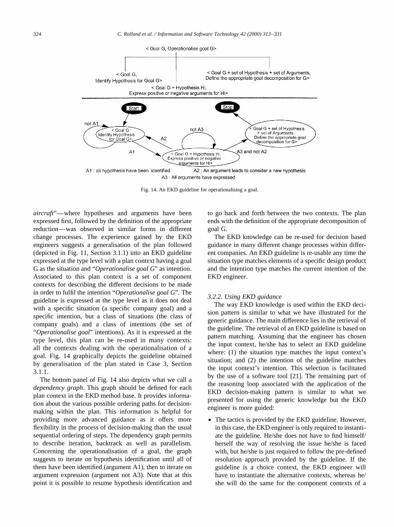
aircraft”—where hypotheses and arguments have beenexpressed first, followed by the definition of the appropriatereduction—was observed in similar forms in differentchange processes. The experience gained by the EKDengineers suggests a generalisation of the plan followed(depicted in Fig. 11, Section 3.1.1) into an EKD guidelineexpressed at the type level with a plan context having a goalG as the situation and “Operationalise goal G” as intention.Associated to this plan context is a set of componentcontexts for describing the different decisions to be madein order to fulfil the intention “Operationalise goal G”. Theguideline is expressed at the type level as it does not dealwith a specific situation (a specific company goal) and aspecific intention, but a class of situations (the class ofcompany goals) and a class of intentions (the set of“Operationalise goal” intentions). As it is expressed at thetype level, this plan can be re-used in many contexts:all the contexts dealing with the operationalisation of agoal. Fig. 14 graphically depicts the guideline obtainedby generalisation of the plan stated in Case 3, Section3.1.1.
The bottom panel of Fig. 14 also depicts what we call adependency graph. This graph should be defined for eachplan context in the EKD method base. It provides informa-tion about the various possible ordering paths for decision-making within the plan. This information is helpful forproviding more advanced guidance as it offers moreflexibility in the process of decision-making than the usualsequential ordering of steps. The dependency graph permitsto describe iteration, backtrack as well as parallelism.Concerning the operationalisation of a goal, the graphsuggests to iterate on hypothesis identification until all ofthem have been identified (argument A1), then to iterate onargument expression (argument not A3). Note that at thispoint it is possible to resume hypothesis identification and
to go back and forth between the two contexts. The planends with the definition of the appropriate decomposition ofgoal G.
The EKD knowledge can be re-used for decision basedguidance in many different change processes within differ-ent companies. An EKD guideline is re-usable any time thesituation type matches elements of a specific design productand the intention type matches the current intention of theEKD engineer.
3.2.2. Using EKD guidanceThe way EKD knowledge is used within the EKD deci-
sion pattern is similar to what we have illustrated for thegeneric guidance. The main difference lies in the retrieval ofthe guideline. The retrieval of an EKD guideline is based onpattern matching. Assuming that the engineer has chosenthe input context, he/she has to select an EKD guidelinewhere: (1) the situation type matches the input context’ssituation; and (2) the intention of the guideline matchesthe input context’s intention. This selection is facilitatedby the use of a software tool [21]. The remaining part ofthe reasoning loop associated with the application of theEKD decision-making pattern is similar to what wepresented for using the generic knowledge but the EKDengineer is more guided:
• The tactics is provided by the EKD guideline. However,in this case, the EKD engineer is only required to instanti-ate the guideline. He/she does not have to find himself/herself the way of resolving the issue he/she is facedwith, but he/she is just required to follow the pre-definedresolution approach provided by the guideline. If theguideline is a choice context, the EKD engineer willhave to instantiate the alternative contexts, whereas he/she will do the same for the component contexts of a
C. Rolland et al. / Information and Software Technology 42 (2000) 313–331324
Fig. 14. An EKD guideline for operationalising a goal.

plan; he/she does not have any thing to do at this stage ifthe context is executable.
• The enactment is identical to what we presented earlier.The EKD engineer makes decisions according to the pre-defined tactics, i.e. selecting the most appropriate alter-native based on the arguments provided by the guidelinein case of a choice context; selecting the adequate path inthe precedence graph to execute a plan context andperforming the action(s) of an executable context tomodify the design product accordingly to the decisionmade.
Let us demonstrate the use of EKD guidance in the caseof our example with the contextkGoal G1 “Minimise riskbefalling aircrafts”, Operationalise Goal G1l. The contextmatches the situation and decision of the guideline depictedin Fig. 14. The instantiation of the pre-defined componentcontexts is illustrated in Fig. 15. The enactment is identicalto what was presented in Section 3.1.1 (Case 3). In fact, theguideline shown in Fig. 15 was obtained by generalising theplan context that has been previously constructed using thegeneric guidance.
By following the heuristical knowledge embedded in theEKD guideline, the engineer is constantly guided. Part ofthe solution he/she has to find is provided by the guideline.Suggestions are made on the alternative strategies he/shecan follow, pre-defined arguments supporting or objectingto these strategies are provided, pre-defined plans he/she canuse for reaching his/her decision are readymade, he/she istold what to do next, etc.
3.3. Domain-specific guidance
Domain-specific guidanceis based ondomain-specificknowledge. The domain-specific knowledge aims at provid-ing guidance to EKD engineers for solving well-focusedproblems related to a specific domain. It is grounded onexperience based knowledge and suggests to re-use and toadapt concrete and already tested solutions that have showntheir efficiency and feasibility in different organisationalsettings of the same domain. The benefit of using this typeof knowledge is that it considerably shortens the decisionprocess of solving domain-specific problems by offeringready to use solutions.
3.3.1. Modelling domain-specific knowledgeFor instance, in the context of ATC, domain specific
knowledge could suggest that the operationalisation of thegoal G1: “Minimise risk of befalling aircraft” can beachieved in two alternative ways. It can be either a decom-position of G1 into two complementary goals G2: “Maintainseparation standards” and G3: “Decrease risk of humanerror” or a decomposition with G3 and G4: “Limit thenumber of aircrafts allowed to cross controlled airspace”.
Similar to the case of generic and EKD knowledge,domain specific knowledge is captured in guidelinesexpressed as hierarchies of contexts of the three differenttypes. However, domain-specific knowledge is described atthe instance level. It deals with process intentions related toconcrete facts such as the intention of operationalising theairport goal of “Minimising the risk of befalling aircraft”, or
C. Rolland et al. / Information and Software Technology 42 (2000) 313–331 325
Fig. 15. Instantiating the EKD guideline depicted in Fig. 14.

the intention of modelling the design solution based on “theidentification of customers’ baggage using bar-codes”.
Fig. 16 depicts the guideline related to the operation-alisation of the goal G1 as introduced above. In additionto the two alternative contexts describing the two waysof operationalising the goal “Minimise risk of befallingaircrafts”, an argument is provided (A1) to help theselection of the most appropriate alternative.
3.3.2. Using domain-specific guidanceThe use of domain-specific knowledge within the EKD
decision-making pattern is very close to what has beenpresented in Section 3.2 for EKD guidance. The differencelies in the fact that domain-specific guidelines are definedat the instance level and, therefore, do not have to beinstantiated while being used.
The reasoning loop starts with the retrieval of the domain-specific guideline matching the input context. This can bedone manually by the EKD engineer who browses thelibrary and looks for a guideline where the situation is theinput context’s situation and the intention is the inputcontext’s intention. It is more easily made with the use ofthe EKD tool environment which could realise the matchingautomatically [21], this has not been implemented yet. Ifthere exists a guideline that matches, the EKD engineercan decide to use it. The guideline provides tactics forfulfilling the intention. The engineer has just to implementthem.
Let us reconsider our example with the input contextkGoal G1 “Minimise risk of befalling aircrafts”, Operatio-nalise Goal G1l. Because this context is the same than thetop context of the domain-specific guideline depicted inFig. 16, this guideline can be selected by the engineer.Enacting the guideline consists in studying the twosuggested alternatives, evaluating the argument—that is tofind out if “the rate of human errors is below the interna-tional norm no. 1234” and then, selecting the alternative he/she believes to be the most appropriate. Assume the airporthas a high rate of human errors, therefore the engineerchooses the alternative suggesting to perform an ANDreduction on goal G1 with the two goals G2: “Decreaserisk of human errors” and G3: “Maintain separationstandards”. This alternative is an executable context andits associated action precisely describes how to modify the
design product in order to get the adequate reduction forgoal G1 in the product.
4. EKD guidelines overview
As presented in Section 3, the guidelines are modelledwith our process meta-model in terms ofcontextsandtreesof contexts.Besides they are clustered in three classes: (1)The generic guideline; (2) EKD guidelines; and (3) thedomain-specific guidelines.
As highlighted in Section 3, each class of guideline isused by the decision-making pattern to provide a specifictype of guidance (generic guidance, EKD guidance anddomain-specific guidance, respectively). This section aimsto present the following: (1) a brief overview of the EKDguidelines; and (2) to demonstrate the use of some of them.
4.1. The EKD guidelines matrix
We use amatrix presentationto overview the collectionof EKD guidelines. These guidelines are thematrixelements. The columnsof the matrix areintentionswhicharise during the EKD process. “Operationalise goal”,“Classify goal” “ Identify goal” are examples of suchintentions. For the sake of readability, we use only intentionnames whereas for the full context heading, i.e. a situationname–an intention name, is really meant. Five mainintentions are identified: (1) model the current enterprisestate; (2) acquire goal; (3) operationalise goal; (4) generatedesign models; and (5) Validate design models. Some ofthem are decomposed in a number of sub-intentions thatare visualised in the matrix as sub-columns. Therows ofthe matrix aretechniquesused in the guidelines. The sametechnique can be used in different ways in different guide-lines. For example, SWOT analysis is a technique whichmight be used for satisfying the intention of “Analyse thecontext of change” and for “Argument reduction(of a goal)”as well. The matrix of Fig. 17 summarises how techniquesare embedded in EKD guidelines to support the variousEKD process intentions.
As we have seen in Section 3.2.1, the EKD guidelinespresented in the matrix are domain independent. They cansupport the construction of the EKD Models for a givencompany, the expression of alternative strategies forchange, brainstorming activities, etc.
C. Rolland et al. / Information and Software Technology 42 (2000) 313–331326
Fig. 16. An example of a domain-specific guideline.

The knowledge embedded in the EKD guidelines isexpressed using the process meta-model developed inSection 3.1. These guidelines can be re-used for decision-based guidance in different change processes withindifferent companies.
4.2. Illustrating the set of guidelines supporting the“Classify goal” intention
This section presents the set of guidelines provided forclassifying goals. Goal classification occurs after goalacquisition. The aim of the classification is to producesome partial views of the problem, each category focusingon different aspects of change and thus conforming to differ-ent needs. By doing so, the different stakeholders are able toconcentrate on different facets of change separately and toimprove their overall understanding of the problem, thusleading to the possible identification of new goals. Goalclassification leads to organise goals into coherent clusters.
Four guidelines are available for the intention “Classifygoal”. The first one does not suggest to use any pre-definedcategory [31], whereas the two others are based on existingcategories proposed in the literature [32,33], and arerelevant for classifying goal in the context of supportingthe change process in an organisation. We present these
guidelines in turn and illustrate how they provide guidancethrough some examples.
4.2.1. Classifying goals with user defined categoriesAccording to [31], goal classification based on user
defined categories is relevant for handling changes and forstructuring a complex domain with user-defined views.Guiding such a classification is supported by the guidelinedepicted in Fig. 18. The top context is:k(Goal G 1 a set ofuser defined categories), classify Gl. The situationcomprises a goal G and a set (possibly empty) of alreadydefined categories. The guideline suggests to follow a planhaving two components: (1) to start by defining the appro-priate category; and (2) to place the goal in the category.However, as shown in the dependency graph, it is possibleto directly place the goal being studied in an existingcategory (if A3 is true). Furthermore, after having cate-gorised a goal, it may be necessary to re-organise categoriesif one category contains too many goals (if A2 is true). Inthis case, the engineer is guided to define sub-categories andthen to re-organise the classification scheme. Finally, a goalcan belong to several categories, the EKD engineer isguided towards multiple classification because of the loopput on the contextk(Goal G1 a set of categories C), PlaceG in Cl (if A4 is true).
Let us consider that the goal acquisition phase has led to
C. Rolland et al. / Information and Software Technology 42 (2000) 313–331 327
Fig. 17. The EKD guidelines.

the emergence of the following list of goals: (G1)improve air-traffic flow; (G2) reduce demands placedon controllers; (G3) minimise risk of befalling aircrafts;(G4) reduce delays; (G5) reduce noise and (G6) reducefuel consumption.
Assuming that no category has been defined so far,classifying goal G1 “Improve air-traffic flow” would beguided as follows. First, category definition is asked(because A3 is false), this leads to the identificationof the “Efficiency” category. Then, the guidelinesuggests to place G1 in a category, i.e. “Efficiency”.Similarly, goal G2 is placed in two new categoriescalled “Controller” and “Safety”. The classification ofgoal G3 leads to directly place it in the existing“Safety” category. Similarly, goals G4 and G5 are putin the existing category “Efficiency”. While classifyinggoal G6, the EKD engineer is suggested to refine thecategory “Efficiency” and is guided towards the identi-fication of more specialised categories, such as “Costefficiency”, “Noise efficiency”, etc.
4.2.2. Classifying goals following a behaviour orientedclassification
The following guideline is based on the classificationproposed in Ref. [32]. This classification suggests to clustersgoals according to the impacts they have on the set ofpossible behaviours of the system. Five categories areadvocated: Achieve, Cease, Maintain, Avoid and Optimise.Achieve and Maintain generate behaviours, Cease andAvoid restrict behaviours, whereas Optimise comparesbehaviours (Fig. 19).
The guideline suggests to study five alternatives forclassifying a goal with regard to its impact on the systembehaviour. The different arguments provided for each alter-native shall be carefully studied. Indeed, arguments areprovided to help in the selection of the most appropriateone. Each alternative context is an executable context itsassociated action adds the corresponding category to thegoal description.
Let us apply this guideline to the goal “No passengershould miss his/her correspondence”. Let us assume that,
C. Rolland et al. / Information and Software Technology 42 (2000) 313–331328
Fig. 19. The guideline for behaviour oriented classification.
Fig. 18. The guideline for classifying a goal using user defined categories.

after a careful study of the different arguments, the EKDengineer decides that the argument 3 applies, i.e. “this goalmust be fulfilled all the time in the future. The enactment ofthe corresponding alternative adds the category “Mainte-nance goal” to the description of the goal“No passengershould miss his/her correspondence”.
4.2.3. Classifying goals into private goals and differenttypes of system goals
This guideline advocates to distinguish between privategoals and system goals and to refine system goals. It is basedon the classification proposed in Ref. [32]. Private goals aregoals thatmight be achieved by the system. System goalsare application specific goals thatmustbe achieved by thesystem. Furthermore, several sub-categories have beendefined for system goals, namely,Satisfaction goals,Information goals, Robustness goals, Consistency goals,Safety goalsand Privacy goals. Satisfaction goals areconcerned with satisfying agents’ requests. Informationgoals are concerned with getting agents informed aboutobject states. Robustness goals are concerned with recover-ing from foibles of human agents or from breakdowns ofautomated agents. Consistency goals are concerned withmaintaining the consistency between the automated andthe physical part of the system. Safety goals and Privacygoals are concerned with maintaining agents in states,which are safe and observable under, restricted conditions,respectively.
The guideline embedding such a knowledge is depicted inFig. 20. The top-level context is a choice context with twoalternatives, each alternative corresponding to respectivelyprivate and system goals. The contextkGoal G, Classify Gas system goall is a choice context. It has six alternatives,each one related to one of the categories we just mentioned.Indeed, arguments are provided for each alternative, they
are based on the definition of each goal category. All theother contexts depicted in Fig. 20 are executable contexts,their actions add a category to the goal described in thesituation.
Let us take two examples to show how guidance can beprovided by this guideline. We first consider the goal“Maintain safe transportation”. The guideline suggests todecide if the goal must or might be fulfilled. Evidently, thisgoal must be fulfilled. Therefore, the alternativekGoal“Maintain safe transportation”, Classify as System goallis selected. Then, the guideline suggests to consider thearguments of the six alternatives and to decide on thoseapplicable. In our example, it is clear that argument 7applies (Goal G is concerned with maintaining agents) ina safe state. Therefore, the contextkGoal “Maintain safetransportation”, Classify as Safety goall is selected. Asthis context is an executable context, its enactment leadsto automatically add two categories to the goal “Maintainsafe transportation”: “System” and “Safety”.
Let us now consider the goal “Avoid plane departuredelay”. As a matter of fact, plane departure delay may bedue to several unpredictable and external causes (the planeis not ready for taking off, the captain is not arrived on time,etc.) and therefore its fulfilment cannot be insured. Havingtaken into account these consideration, the EKD engineerdecides to select the first alternative of the top choicecontext: the contextkGoal “Avoid plane departure delay”,Classify as Private goall. As this context is an executablecontext, its enactment leads to add the “Private” category tothe goal “Avoid plane departure delay”.
5. Conclusion
This paper advocates for effective guidance to conduct
C. Rolland et al. / Information and Software Technology 42 (2000) 313–331 329
Fig. 20. The guideline differentiating private and system goals and refining system goals.

enterprise knowledge modelling and enterprise changemanagement processes based on the use of process models.To this end, we propose:
• an intention based process meta-model for developingprocess models;
• a library of guidelines described as method guidelines atthree levels of abstraction using the concepts defined inthe process meta-model;
• a decision-making pattern using the library of methodguidelines and an enactment mechanism;
• a tool implementing the decision-making pattern [21]with EKD method guidelines [34].
The process meta-model allows us to deal with manydifferent situations in a flexible, decision-oriented manner[14,30]. Moreover, it can support different levels of granu-larity in decision-making as well as non-determinism inprocess performance. It identifies a decision in context asthe basic building block of process models and permits theirgrouping into meaningful modules. Parallelism of decisionsand ordering constraints are also supported.
The decision-making pattern is tailored to provideguidance in all cases. In some cases, the pattern offers adomain-specific guidance. This happens when the librarycontains knowledge about the domain which matches thecurrent context of work. The library contains EKD specificguidelines that are tailored to the way the EKD methodsuggests to work with the different EKD models. Theseguidelines are independent of any particular domain butare based on EKD method knowledge. Finally, if none ofthe two previous types of guidelines matches the currentcontext of work, the generic guideline may operate. It isthe default option in some sense. Clearly, making guidancemore specific increases its efficiency. However, the genericguideline, by offering a general frame for decision-making,makes the EKD process entirely based on guidance.
Taking into account the guidance focus of the decision-making pattern, we can view the reasoning mechanismoffered by the pattern as consisting of two main steps:selecting first, from the library the relevant guideline forthe current situation and intention and, then making decisionaccording to the guideline.
To sum-up, our proposal suggests an incrementalproduction of the enterprise knowledge description. It hastwo major advantages: it makes change traceable and ithelps stakeholders in the change process to share awarenessby making the product under construction being discussed,visible and explicit.
The result of this work has been effectively used in thecontext of the ELEKTRA project (ESPRIT project no.22927) for handling the change in electricity companiesdue to the deregulation rules set by the EC. The EKD guide-lines have been used to produce part of the models describ-ing both the current state and some future states of twoelectricity companies (see [35] for details). Furthermore,in this context, domain-specific guidelines have been
expressed following the proposed framework as changeprocess patterns [36,37].
References
[1] P. Checkland, J. Scholes, Soft Systems Methodology in Action,Wiley, New York, 1990.
[2] R. Espejo, R. Harnden (Eds.), The Viable System Model: Interpreta-tions and Applications of Stafford Beer’s VSM Wiley, Chichester,1989.
[3] R.L. Flood, M.C. Jackson, Creative Problem Solving. Total SystemIntervention, Wiley, New York, 1991.
[4] J. Bubenko, Enterprise modelling, Inge´nierie des Syste`mes d’Infor-mation 2 (6) (1994) 657–678.
[5] S. Decker, M. Daniel, M. Erdmann, R. Studer, An enterprise referencescheme for integrating model based knowledge engineering andenterprise modelling, Proceedings of the 10th European Workshopon Knowledge Acquisition, Modeling and Management, EKAW’97,Lecture Notes in Artificial Intelligence, Springer, Heidelberg, 1997.
[6] K. Hung, T. Simons, T. Rose, The truth is out there?: a survey ofbusiness objects, in: Proceedings of the International Conference onObject oriented Information Systems, Paris, France, September 1998.
[7] S. Jarzabek, T.W. Ling, Model-based support for business reengineer-ing, Information and Software Technology 38 (1996) 355–374.
[8] K. Lewin, in: E. Maccoby, T. Newcomb, E.H. Hartley (Eds.), GroupDecision and Social Change, Readings in Social Psychology,Rinehart & Wisnston, New York, 1958.
[9] V. Gilgeuos, Operations and the Management of Change, Pitman,London, 1997.
[10] J.P. Kotter, Leading change: why transformation efforts fail, IEEEEngineering Management Review, Spring 1997.
[11] M. Dowson, C. Fernstrom, Towards requirements for EnactementMechanisms, in: Proceedings of the European Workshop on SoftwareProcess Technology, 1994.
[12] G. Grosz, C. Rolland, S. Schwer, C. Souveyet, V. Plihon, S. Si-Said,C. Ben Achour, C. Gnaho, Modelling and engineering the require-ments engineering process: an overview of the NATURE approach,Requirements Engineering Journal 2 (1997) 115–131.
[13] J.D. Wynekoop, N.L. Russo, System development methodologies:unanswered questions and the research-practice gap, in: J.I. DeGross,R.P. Bostrom, D. Robey (Eds.), Proceedings of the 14th ICISConference, Orlando, USA, 1993, pp. 181–190.
[14] C. Rolland, C. Souveyet, M. Moreno, An approach for defining ways-of-working, Information Systems Journal 20 (4) (1995) 337–359.
[15] C. Rolland, Understanding and guiding requirements engineeringprocesses, invited talk, IFIP World Congress, Canberra, Australia,1996.
[16] C. Rolland, S. Nurcan, G. Grosz, Guiding the participative designproces, Association for Information Systems Americas Conference,Indianapolis, Indiana, USA, August 1997, pp. 922–924.
[17] ELectrical Enterprise Knowledge for Transforming Applications, TheELEKTRA Project Programme, ELEKTRA consortium, 1996.
[18] P. Loucopoulos, V. Kavakli, N. Prekas, C. Rolland, G. Grosz,S. Nurcan, Using the EKD approach: the modelling component,ELEKTRA Research Report, April 1997.
[19] P. Loucopoulos, V. Kavakli, N. Prekas, C. Rolland, G. Grosz, S.Nurcan, PPC distribution models, ELEKTRA Athena Deliverable,July 1997.
[20] J. Bubenko, J. Stirna, User Guide, February 1997, ELEKTRA internalreport, 1997.
[21] C. Gnaho, J. Barrios, A Web based tool for helping IS engineering inmethod use, in: Proceedings of the Second International Workshop onMany Facets of Process Engineering, Gammarth, Tunisia, May 1999.
[22] C. Rolland, P. Loucopoulos, G.Grosz, S. Nurcan, A framework forgeneric patterns dedicated to the management of change in the
C. Rolland et al. / Information and Software Technology 42 (2000) 313–331330

electricity supply industry, in: Proceedings of the Ninth InternationalWorkshop on Database and Expert Systems Applications, DEXA’98,Vienna, Austria, August 1998, pp. 907–912.
[23] V. Kavakli, P. Loucopoulos, Goal-driven business process analysis—application in electricity deregulation, in: Proceedings of 10th Inter-national Conference CAISE’98, Pisa, Italy, June 1998, pp. 305–324.
[24] S. Si-Said, C. Rolland, G. Grosz, MENTOR: a computer aidedrequirements engineering environment, in: Proceedings of the EighthCAISE Conference on Challenges in Modern Information Systems,Heraklion, Crete, Greece, May 1996.
[25] TEMPORA Esprit project, Final report, 1994.[26] N. Nilsson, Problem Solving Method in Artificial Intelligence,
McGrawHill, New York, 1971.[27] Wilenski, Planning and Understanding, Addison Wesley, Reading,
MA, 1983.[28] N. Prat, Using machine learning techniques to improve informations
systems development methods, in: Proceedings of AmericasConference on Information Systems, Phoenix, USA, August 1996.
[29] A.V. Lamsweerde, Learning Machine Learning, Introducing a LogicBased Approach to Artificial Intelligence, 3, Wiley, NewYork, 1991pp. 263–356.
[30] S. Nurcan, C. Rolland, Meta-modelling for co-operative processes, in:Proceedings of the Seventh European-Japanese Conference onInformation Modelling and Knowledge Bases, Toulouse, France,May 1997, pp. 297–315.
[31] P. Loucopoulos, P. Louridas, V. Kavakli, A. Tzanaki, D. Fillipidou,Contribution to the EKRD Approach, ELEKTRA Research Report,UMIST, Manchester, UK, October 1996.
[32] A. Dardenne, A.v. Lamsweerde, S. Fickas, Goal-directed require-ments acquisition, Science of Computer Programming 20 (1993)3–50.
[33] A. Anton, Goal-based requirements analysis, in: Proceedings of ICRE‘96, IEEE, Colorado Springs, CO, USA, 1996, pp. 136–144.
[34] S. Nurcan, C. Rolland, Using EKD-CMM electronic guide book formanaging change in organisations, in: Proceedings of the NinthEuropean-Japanese Conference on Information Modelling andKnowledge Bases, Iwate, Japan, May 1999, pp. 105–123.
[35] P. Loucopoulos, V. Kavakli, N. Prekas, I. Dimitromanolaki, N.Yilmazturk, C. Rolland, G. Grosz, S. Nurcan, D. Beis, G. Vgontzas,System design specification for PPC, ELEKTRA Demetra Deliver-able, March 1998.
[36] N. Prekas, P. Loucopoulos, C. Rolland, G. Grosz, F. Semmak, Usingpatterns as a mechanism for assisting the management of knowledgein the context of conducting organisational change, in: Proceedings ofthe 10th International Workshop on Database and Expert SystemsApplications, DEXA’99, Florence, Italy, September 1999.
[37] C. Rolland, G. Grosz, S. Nurcan, W. Yue, C. Gnaho, An electronichandbook for accessing domain specific generic patterns, in: Proceed-ings if the IFIP WG 8.1 Working Conference: Information Systems inthe WWW environment, Beijing, Chine, July 1998, pp. 89–111.
C. Rolland et al. / Information and Software Technology 42 (2000) 313–331 331