A completely digital SSB exciter - I0CG · 2011-01-03 · Symposium SDR – Modena 11 Aprile 2010....
36
12th Convention on Digital & Radio Communications Castelfeder 3-4 October 2010 SDT Note the ‘T’ A completely digital SSB exciter Hardware by Giuliano I0CG, Software by Alberto I2PHD English text by John F5VLF/G3PAI
Transcript of A completely digital SSB exciter - I0CG · 2011-01-03 · Symposium SDR – Modena 11 Aprile 2010....

12th Convention on Digital & Radio Communications
Castelfeder 3-4 October 2010
SDTNote the ‘T’
A completely digital SSB exciter
Hardware by Giuliano I0CG, Software by Alberto I2PHDEnglish text by John F5VLF/G3PAI
Alberto I2PHD
Symposium SDR – Modena 11 Aprile 2010
SDR – Software Defined Radio or….
SDR – Software Defined Receiver ?
Often, unconsciously, we use the second definition…
What do we mean by SDR ?

Alberto I2PHD
Symposium SDR – Modena 11 Aprile 2010
But with SDR techniques, based on software, it is possible to produce a fully digital transmitter, where the input signal is first of all digitised and
then used to produce an SSB transmission, with digital conversion to the final frequency.
In practice
DigitalUpConversion

Alberto I2PHD
Symposium SDR – Modena 11 Aprile 2010
D U C k - Donald Duck….

Alberto I2PHD
Symposium SDR – Modena 11 Aprile 2010
SSB “modulation” is really a translation of the input signal from baseband to the final
transmission frequency

Alberto I2PHD
Symposium SDR – Modena 11 Aprile 2010
But it is not enough to consider positive frequencies. In this case we must also
include negative ones….

Alberto I2PHD
Symposium SDR – Modena 11 Aprile 2010
So, taking into account the negative frequencies as well, this is what is
really going on:
Pity the LSB has appeared, as we don't want it…

Alberto I2PHD
Symposium SDR – Modena 11 Aprile 2010
How to get rid of it? Obviously by software…

Alberto I2PHD
Symposium SDR – Modena 11 Aprile 2010
Quartz filter? You are joking! That's not software…
Phasing method ? Perhaps…. but this involves producing the LSB and then cancelling it out…
But wait a minute… what about the third method … what was it called ?
Weaver…
Alberto I2PHD
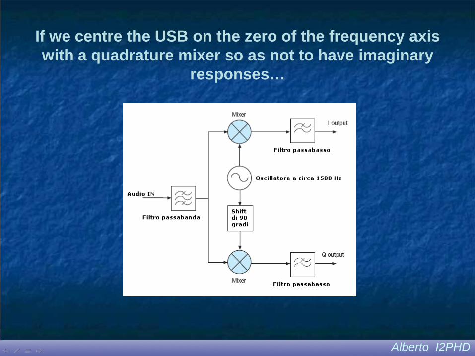
Symposium SDR – Modena 11 Aprile 2010If we centre the USB on the zero of the frequency axis with a quadrature mixer so as not to have imaginary
responses…

Alberto I2PHD
Symposium SDR – Modena 11 Aprile 2010
… and if we remove the LSB with a real lowpass filter (which when viewed in the
complex plane is really bandpass)…

Alberto I2PHD
Symposium SDR – Modena 11 Aprile 2010
OK, but do we have to perform two multiplications for every input sample?
Suppose, instead of switching the signal, we switch the filter?

Alberto I2PHD
Symposium SDR – Modena 11 Aprile 2010
I prefer this idea … if we save a little
(so long as we do save) …
Clearly the filter now has to have complex coefficients …

Alberto I2PHD
Symposium SDR – Modena 11 Aprile 2010Fine. Now we have the two components I and Q which
describe the analytical signal representing the USB, but they are at baseband … they have to be shifted to the
final output frequency.
If for example we wish to transmit on a frequency of 100 MHz, a modulator is needed with a half-complex mixer
with a sampling frequency of at least 250 MHz…
Alberto I2PHD
Symposium SDR – Modena 11 Aprile 2010
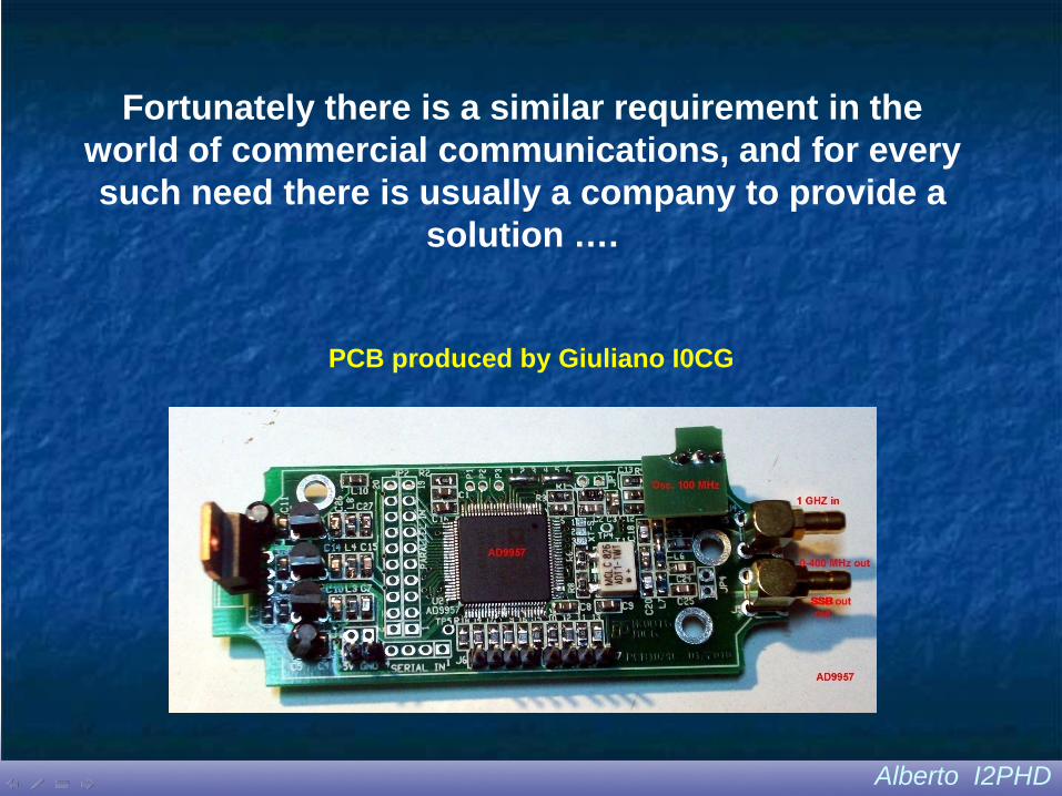
Fortunately there is a similar requirement in the world of commercial communications, and for every such need there is usually a company to provide a
solution ….
PCB produced by Giuliano I0CG
Alberto I2PHD
Symposium SDR – Modena 11 Aprile 2010
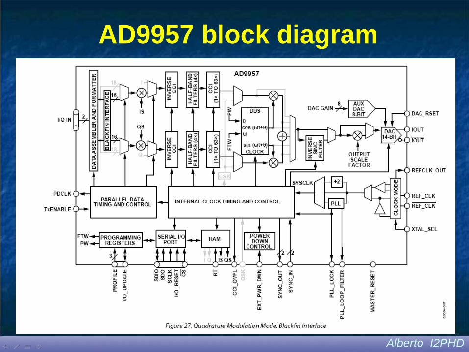
AD9957 block diagram

Alberto I2PHD
Symposium SDR – Modena 11 Aprile 2010The AD9957 has a series of internal programmable
interpolators, for ratios of up to 1008. The input signal should therefore be in I/Q format with a sampling
frequency of :
2.5E8 / 1008 = circa 248016 Hz
The best way to do this is to sample the audio at 1/16th
of this rate - that is circa 15501 Hz - filter at that frequency with the complex filter previously
mentioned, and then interpolate x 16

Alberto I2PHD
Symposium SDR – Modena 11 Aprile 2010We can do it with a convenient low-cost component, the dsPIC from Microchip. A fairly conventional PIC, with an on board ADC and a DSP core capable of 50 milion MAC
operations per second. Not bad for a 5 dollar chip…
And you can also get it in a 28 pin DIP version…

Alberto I2PHD
Symposium SDR – Modena 11 Aprile 2010
Advantages of the dsPIC
• Compatibility with a standard PIC• Free compiler (demo version)• Components cost only a few euros• Available in 28 pin DIP• The high level of integration of this component,
containing all the necessary peripherals, hasgreatly simplified the hardware on the circuitboard which now is essentially just the dsPIC.

Alberto I2PHD
Symposium SDR – Modena 11 Aprile 2010
Advantages of the dsPIC (2)Inside the DSPIC33F128GP802 used for the project
• 128kb flash memory: 2% used• 16 Kword RAM: 80% used• 12 bit ADC used for sampling the microphone
signal• 16 bit ADC used in the debug phase (to observe
the I/Q signals in analogue mode)• 2 SPI interfaces used to transfer I/Q digital data t
the DUC AD9957• 2 Timers to control the timing of sampling and
transmission to the DUC
Alberto I2PHD
Symposium SDR – Modena 11 Aprile 2010So, to sum up, the dsPIC digitises the audio at 15501 Hz, eliminates the LSB with a complex filter, and then perform a x 16 interpolatione,
bringing the sampling frequency to 248016 Hz.
At this point the I and Q samples are sent, in Q15 format, to the AD9957 through a double serial interface of type SPI (Serial Peripheral Interface), and the AD9957 does its dirty work. It
produces USB (or optionally LSB, changing the sign of the imaginarypart of the Numerically Controlled Oscillator), with an output
frequency between, say, zero and 100 MHz, so as not to get tooclose to the Nyquist limit (125 MHz).

Alberto I2PHD
Symposium SDR – Modena 11 Aprile 2010A few graphs showing the results obtained when
designing the filters with Matlab
Variation with frequency of the output of the complex filter, taking account of rounding the coefficients to 16 bit
Alberto I2PHD
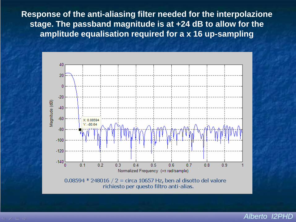
Symposium SDR – Modena 11 Aprile 2010Response of the anti-aliasing filter needed for the interpolazione stage. The passband magnitude is at +24 dB to allow for the
amplitude equalisation required for a x 16 up-sampling

Alberto I2PHD
Symposium SDR – Modena 11 Aprile 2010Simulation with Matlab of the rejection of the unwanted sideband.
With 1500 Hz input, we achieve more than 88 dB

Alberto I2PHD
Symposium SDR – Modena 11 Aprile 2010The resulting USB signal, received in a 60 kHz
bandwidth on a Perseus, is very clean….
Alberto I2PHD
Symposium SDR – Modena 11 Aprile 2010
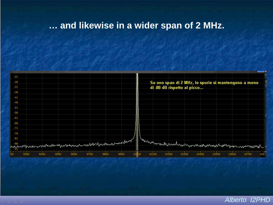
… and likewise in a wider span of 2 MHz.

Alberto I2PHD
Symposium SDR – Modena 11 Aprile 2010
Carrier attenuation : 79 dBUnwanted sideband attenuation : 80 dB2 harmonic attenuation : > 80 dB3 harmonic attenuation : > 75 dB
Quality of the generated SSB signal

Alberto I2PHD
Symposium SDR – Modena 11 Aprile 2010AD9957 phase noise(Single tone mode)

Alberto I2PHD
Symposium SDR – Modena 11 Aprile 2010First prototype produced by Giuliano I0CG

Alberto I2PHD
Symposium SDR – Modena 11 Aprile 2010First prototype produced by Giuliano I0CG

Alberto I2PHD
Symposium SDR – Modena 11 Aprile 2010The SSB driver card in the photo (the work of Giuliano I0CG) contains:
1) Microphone preamp2) Compressor + noise gate 3) Anti-alias filter cutting off at 3.5 Khz 4) dsPIC
On top is the AD9957 auxiliary board with RF SSB output at 0 dBm.The metal work below the PCB houses the front panel.It does not need any cabling.
Alberto I2PHD
Symposium SDR – Modena 11 Aprile 2010
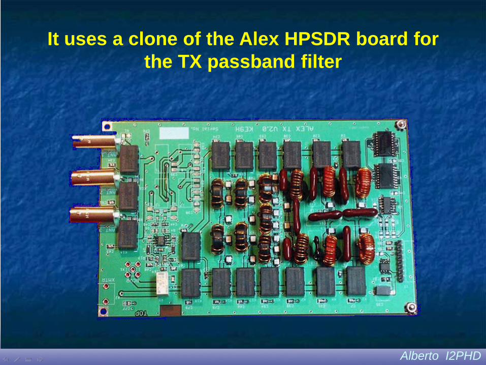
It uses a clone of the Alex HPSDR board for the TX passband filter

Alberto I2PHD
Symposium SDR – Modena 11 Aprile 2010CAT Protocols used 1) Kenwood protocol modified for WINRAD (uses
a DLL by I2PHD for SDRX)
2) Kenwood protocol for POWER SDR
3) ICOM protocol for Perseus or original ICOM RX
These are managed by an emulation of a COM serial port via a photo-coupled USB interface

Alberto I2PHD
Symposium SDR – Modena 11 Aprile 2010
Using the RTX with the Perseus RX
In this case the AD9957 is only used on transmit. On receive, the Perseus does not
require a DDS for direct sampling at RF.So what shall we do with the DDS when we
are on receive?It can be used as a tracking generator for
analysing filters or antennas.

Alberto I2PHD
Symposium SDR – Modena 11 Aprile 2010Filter analysis using the Perseus RX, with the DDS as a sweep
generator

Alberto I2PHD
Symposium SDR – Modena 11 Aprile 2010Well, that's it. There are already at least 3 SDTs in use, and when working the USA they get repeated
unsolicited reports on the quality of their signals.
See you on the air with Donald !