A ccelerator P hysics and E ngineering Josef Frisch Tonee ... · CTF3 - Test facility for a linear...
42
1 Accelerator Physics and Engineering Josef Frisch Tonee Smith Clive Field Alan Fisher Henrik Loos Jeff Rzepiela Mark Petree Steve Smith Jim Welch Glen White Walter Wittmer Mark Woodley Gerald Yocky
Transcript of A ccelerator P hysics and E ngineering Josef Frisch Tonee ... · CTF3 - Test facility for a linear...

1
Accelerator Physics and Engineering
Josef FrischTonee Smith
Clive FieldAlan FisherHenrik Loos
Jeff RzepielaMark PetreeSteve SmithJim WelchGlen WhiteWalter WittmerMark WoodleyGerald Yocky
2
APE – What do we do?Mission: Make accelerators work
Work in the intersection between physics, engineering and operations
Hardware design, construction and commissioning
High level software for beam modeling, diagnostics and controls
Machine operations and commissioning and experiments
Non-experts, non-specialists

3
Types of ProjectsLong-term projects:ATF2 tuning, THz source
Fast and simple:X-ray diagnostics, RF interlocks
Cutting-edge systems:10fs timing, Proton synchrotron light monitor
Simple brute-force: X-ray shutter, RF interlocks
Fast clean-up of systems that were delayed or non-functional: Get it working, make it pretty later.

4
Involvement in Major Projects● ATF2 - Linear Collider final focus test, Located at KEK – Japan
● Modeling, Beam Position Monitors● CTF3 - Test facility for a linear collider located at CERN
● Beam Position monitors● FACET - Plasma wakefield accelerator test at SLAC
● Installation management, commissioning, diagnostics● LCLS - Worlds first hard X-ray laser at SLAC
● Modeling, High level controls, Diagnostics, THz source● LHC - High energy proton collider located at CERN
● Proton Synchrotron light monitor, Experiment timing.APE works in collaboration with other groups – no APE-only projects
Will just present a few selected projects

5
TCAV Bunch Length MeasurementTransverse cavity provides time dependent kick
Optics for 90 degree phase advance
Longitudinal transformed to transverse
Profile monitor
- 1 5 0 0 - 1 0 0 0 - 5 0 0 0 5 0 0 1 0 0 0 1 5 0 01 0 0 0
1 5 0 0
2 0 0 0
2 5 0 0
3 0 0 0
3 5 0 0
4 0 0 0
4 5 0 0x a r e a = 0 . 4 6 ± 0 . 0 0 M c t sx m e a n = 0 . 0 2 ± 0 . 0 0 m mx r m s = 1 5 9 . 7 ± 0 . 0 0 µ m
y a r e a = 0 . 4 2 ± 0 . 0 0 M c t sy m e a n = - 0 . 0 2 ± 0 . 0 0 m my r m s = 5 0 . 5 ± 0 . 0 0 µ m
P o s i t i o n ( µ m )
Cou
nts
()
- 1 - 0 . 5 0 0 . 5 10
5
1 0
1 5
2 0
2 5
3 0
3 5
4 0
4 5
T C A V : L I 2 4 : 8 0 0 : T C 3 : A A C T ( n o r m )
Bea
m S
ize
( µm)
T C A V b u n c h l e n g t h o n W I R E : L I 2 8 : 7 4 4 1 5 - J u n - 2 0 1 0 1 7 : 5 8 : 0 4 S u p e r
σ y = 3 6 . 9 3 ± 2 . 0 0 µ m
σ z = 2 . 5 1 6 ± 0 . 6 4 7 µ m
c a l = 7 . 6 8 5 ± 0 . 3 4 7 µ m / µ m
LCLS uses a wire scanner to measure the profile
<10 fs bunch length measurement
TCAV + phase, - phase and off
TCAV on / off
15MV 2856MHz at LCLS
H. LoosH. Loos

6
LCLS Short BunchesOperate with 20pC, near max compression, bunch length below TCAV resolution
Simulations (Genesis) indicate ~7fs FWHM bunch length (Yuantao Ding)
20pC, 160uJ, 9 KeV
Indirect bunch length measurement: FEL operates 1° L2 phase either side of full compression, but not at full compression (believed due to emittance growth)
0° phase 1°phase
No Lasing Good lasing

7
Precision Timing● LCLS produces few-femtosecond X-ray pulses● Experiment laser produces ~40fs pulses
● Commercial lasers available to ~20fs● HHG can generate <1 fs XUV pulses.
● Pump-probe experiments could use fs timing● LCLS LINAC jitter (shot to shot relative to a
perfect clock) is ~60fs RMS● Probably limited by high power RF system – very
expensive to improve● Need to measure beam time and correlate with
experiments

8
Beam arrival time cavity (LCLS)Similar to a cavity BPM but use the monopole mode
Phase drift from cavity temperature is the most significant problem
1us time constant, 10-5 /C° temperature coefficient -> 10ps/C° (!)
Raw Signal
Phase slope gives cavity temperature

9
Beam Arrival Time System
Cavity system installed and used for all pump/probe experiment since the start of the LCLS experimental runs M. Petree

10
Beam Arrival Time Cavity - NoiseCompare 2 independent cavity systems to estimate noise
Present system designed for 250pC, needs more gain to operate properly at low charge
20pC
RMS difference between cavities ~12 femtoseconds RMS at 250pC, ~25 femtoseconds at 20pCDrift is ~100 femtoseconds p-p over 1 day.

11
Full Timing System
M. Petree, LBNL timing group. LCLS Laser group

12
Timing System Performance 50fs RMS
From R. Coffee experiment. Pretty good, but need to eventually do much better
13
Timing Upgrades
Phase Detector
Laser amplifier chain
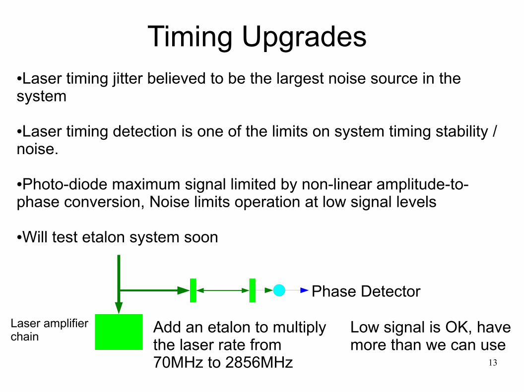
●Laser timing jitter believed to be the largest noise source in the system
●Laser timing detection is one of the limits on system timing stability / noise.
●Photo-diode maximum signal limited by non-linear amplitude-to-phase conversion, Noise limits operation at low signal levels
●Will test etalon system soon
Add an etalon to multiply the laser rate from 70MHz to 2856MHz
Low signal is OK, have more than we can use

14
Future TimingElectronic timing likely not possible below ~10fs, need direct measurement of X-ray vs. Laser time in the experimental chamber
GaAs or similar
Laser
X-rays Reflected optical beam measured on array sensor
X-rays generate carriers that change the index of refraction and change the reflectivity near Brewsters angle
Suggested by a many people, not sure who originiated the idea.Initial tests at SXR

15
“Slotted Foil” short bunches
6 µm emittance
1 µm emittance
“V” Foil position scan
No direct pulse length measurement
Slotted foil designed by P. Emma, installed by C. Field, M. Petree, D. Karach

16
Low Charge AND Slotted Foil
X-ray spectrum with 20pc operation – few spikes suggest ~5 fs pulses
With 20pc and slotted foil see single spike spectrum suggests very short pulses
No direct measurement but may be producing ~1fs X-ray pulses
Various combinations of high / low charge and slotted foil used by multiple experiments during the 2010 LCLS experiment run
17
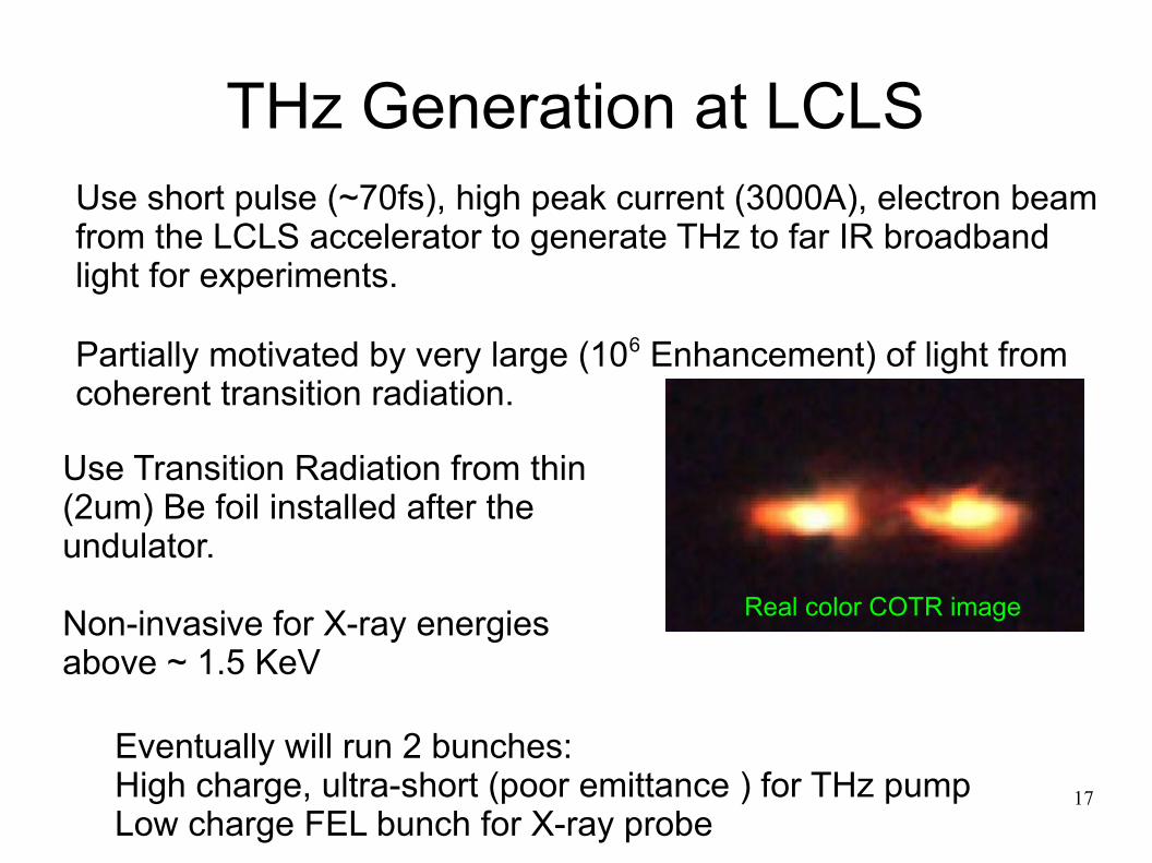
THz Generation at LCLSUse short pulse (~70fs), high peak current (3000A), electron beam from the LCLS accelerator to generate THz to far IR broadband light for experiments.
Partially motivated by very large (106 Enhancement) of light from coherent transition radiation.
Real color COTR image
Use Transition Radiation from thin (2um) Be foil installed after the undulator.
Non-invasive for X-ray energies above ~ 1.5 KeV
Eventually will run 2 bunches:High charge, ultra-short (poor emittance ) for THz pumpLow charge FEL bunch for X-ray probe

18
THz System
bolometer
Pyro detector
Pyro cam.THzAuto-correlation
Sample stage/pinhole xyz stage
flip mirroriris
Motorized filter set
Laser
QWP
ZnTe
BS
EO samplingBalanced
Diodes/Andor
T2A
T,2A
T
2A
3T
2A
R
R
T
Alignmentlaser
2A
Delay stage
2A
BS
2A
Half wave plate R
flip mirror
e−
Simulation by H. LoosA. Fisher, A. Lindenberg (PULSE)
~3V/Å Electric FieldLab source: .01V/Å
Experiment laser800nm20fs pulses68 MHz, 150mW
Characterize THz, then use for experiments

19
THz StatusOptics installed in tunnel, expect to test with beam soon

20
X-ray Beam Diagnostic StationAfterthought in LCLS Design – constructed to replace the unfinished Front End Enclosure
Now used as a general purpose X-ray diagnostics chamber
Insert-able samples (15): materials tests, X-ray edge filters
YAG screen (upstream X-ray spot size monitor)
B4C MPS stopper to protect downstream PPS stoppers
BEAM
T. Smith, E, Kraft
First LCLS lasing seen with this system

21
X-ray Diagnostic Station
Diagnostic station filter set
Thermal-acoustic sensor for calibrated X-ray measurements under development
X-rays → heat → acoustic wave → ultrasonic microphone

22
LCLS Apps● Optimization: Correlation plot -> Emittance ->
(profile monitor, or wire scanner app).● Very powerful tool – for example can scan orbit
bump in the LINAC to minimize emittance● Analysis: Undulator K measurement,
wakefields, , Bunch length, profiles, etc. ● Modeling: Matlab, XAL, etc.
Configuration in Mad / Oracle database
M. Woodley

23
LCLS High Level AppsCorrelation plot
EmittanceApplication
Profile Monitor
Integrated set of applications for beam measurement and optimization H. Loos
J. Rzepiela

24
LCLS Apps (Sample only)Matching, XAL or Matlab model
Emittance vs gun Solenoid
Transverse cavity bunch length measured with wire scanner vs phase

25
X-ray Self Seeding at LCLS
Working in collaboration with photon science and ANL to make a self-seeding tests at LCLS at 1Å in spring of 2011

26
LCLS_II
Calculations for wide range (200eV to 20 KeV) X-ray gas attenuator using variable apertures
Avoid speckle from Be attenuator. Investigating other materials

27
J. Welch

28
FACET
Lots of activity getting 2km of accelerator, 2 damping rings, a positron source and a new beamline ready. (W. Whittmer, J. Yocky)

29
FACET
Fixed Foil
Pyro Detector
CCD Camera
Diamond Window
Si Beam Splitter
e-Beam
New Database, ModelM. Woodley
FACET bunch length monitors modified from LCLS designAlso used as OTR monitorH. Loos

30

31
ATF2

32
ATF2 Tuning / Controls● Main system used = VSYSTEM + SAD online model
● Mainstay for accelerator operations, tested, maintained and stable.
● Alternate system developed based on EPICS+ Matlab + Lucretia beam dynamics code: ATF2 “flight-simulator”
● Portable for offsite code development and testing
● Same software runs either in production or simulation mode using simulation mode of low-level EPICS controls.
● Can interface to other code through tcp/ip socket layer or EPICS
DB interface.
33
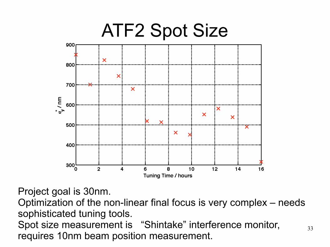
ATF2 Spot Size
Project goal is 30nm.Optimization of the non-linear final focus is very complex – needs sophisticated tuning tools.Spot size measurement is “Shintake” interference monitor, requires 10nm beam position measurement.

34
ATF2 Cavity BPMs
ATF2 I/Q BPM system with 10nm RMS noise
Honda et. al.
LLNL cavity BPM support / mover system
Use 2 BPMS to predict measurement of 3rd
Prediction vs measured
20nm resolution15um range
50nm drif 1 hour

35
Cavity BPM ElectronicsBPM signal6426 MHz
6.7 GHzLow Pass
Reject higher order modes
AmplifierImagerejectMixer
LO 6446 MHz
3 GHzLow pass
filter
Eliminate RF
20dBpre-
amplifier
Low Noise
20MHz
12dBamplifier
High IP3
40MHzlow pass
Anti-aliasfilter
100Ms/s14 bit digitizer
Low cost PC board construct for quantity production6dB noise figure, 70dB linearity measured27nm RMS noise at ATF2

36
ATF2 Project Issues● Magnet Multipoles – may prevent operation
below 250nm with re-measure and shim. ● Need 10nm BPMs to demonstrate 30nm IPspot
size. Possible but this equals the best performance ever seen with BPMs
● ATF2 second goal of 1nm position stability would require 800 picometer cavity BPMS;● Happy to try – but very unlikely to be able to reach
this resolution!

37
CTF3
BPM Signal RF Signals
Facility at CERN to test 2-beam acceleration for the CLIC colliderAPE (S. Smith) working on drive beam BPMs. this is considerably more difficult than it sounds! The drive beam is designed to produce 100s of MW in a power extraction structure – it couples an unmanagable amount of power into any BPM pickup.
One option: use an off-frequency narrow-band BPM and the statistical fluctuations on the drive beam.
power extraction structure

38
LHC – Synchrotron Light Monitor● Two applications:
● BSRT: Imaging telescope, for transverse beam profiles● BSRA: Abort-gap monitor, to verify that the gap is empty
● Particles passing through the abort kickers during their rise get a partial kick and might quench a superconducting magnet.
● Two particle types:● Protons and lead ions
● Three light sources:● Undulator radiation at injection (0.45 to 1.2 TeV)● Dipole edge radiation at intermediate energy (1.2 to 3 TeV)● Central dipole radiation at collision energy (3 to 7 TeV)● Spectrum and focus change during ramp
A. Fisher

39
LHC
To RF cavities and IP4To arc
Cryostat
Extracted light sent to an optical table
below the beamline
1.6 mrad
70 m
26 m 937 mm560 mm
420 mm
D3 U
10 mD4
194 mm

40
LHC Synchrotron LIght monitor Works!
Horizontal0.68 mm 0.70 mm
Vertical0.56 mm 1.05 mm
Light from D3 dipole.Blue filter. Narrow slit.
This Fall: Synchtrotron light images from....LEAD!

41
Other Stuff● Dark matter "Heavy Photon" search at Jeffreson
lab● Design / tests for thin high average power W target.
(C. Field)● Timing system for forward proton detector at
LHC● 1ps timing over 500M in high radiation environment.
● NLCTA: Obvious place for APE to work, but so far too manpower limited

42
Future
● Expect to continue with a random collection of projects using a wide variety of technologies
● APE wouldn't be needed in a perfect lab – but has been valuable in a real one.