
A B C D E F G H JS-5.3 Rotor - massetrecovery.com · *The critical speed range is the range of...
32
JS-5.3 Rotor Used in Beckman Coulter Avanti ® J-20 and J-26 Series, and Avanti ® J-E Centrifuges A B C D E F G H 1 2 3 4 5 6 7 8 9 10 11 12 J-TB-089AE February 2009 ©2009 Beckman Coulter, Inc.
-
Upload
hoangduong -
Category
Documents
-
view
214 -
download
0
Transcript of A B C D E F G H JS-5.3 Rotor - massetrecovery.com · *The critical speed range is the range of...

JS-5.3 Rotor
Used in Beckman CoulterAvanti® J-20 and J-26 Series,and Avanti® J-E Centrifuges
AB
CD
EF
GH
12
34
56
78
910
1112
J-TB-089AEFebruary 2009
©2009 Beckman Coulter, Inc.

2
JS-5.3 Rotor
SAFETY NOTICE
This safety notice summarizes information basic to the safe use of the rotor described in this manual. The international symbol displayed above is a reminder to the user that all safety instructions should be read and understood before operation or maintenance of this equipment is attempted. When you see the symbol on other pages of this publication, pay special attention to the safety information presented. Observance of safety precautions will also help to avoid actions that could damage or adversely affect the performance of the rotor.
Handle body fluids with care because they can transmit disease. No known test offers complete assurance that such fluids are free of micro-organisms. Some of the most virulent—Hepatitis (B and C) viruses, HIV (I–V), atypical mycobacteria, and certain systemic fungi—further emphasize the need for aerosol protection. Handle other infectious samples according to good laboratory procedures and methods to prevent spread of disease. Because spills may generate aerosols, observe proper safety precautions for aerosol contain-ment. Do not run toxic, pathogenic, or radioactive materials in this rotor without taking appropriate safety precautions. Biosafe containment should be used when Risk Group II materials (as identified in the World Health Organization Laboratory Biosafety Manual) are handled; materials of a higher group require more than one level of protection.
This rotor was developed, manufactured, and tested for safety and reliability as part of a Beckman Coulter centrifuge/rotor system. Its safety or reliability cannot be assured if used in a centrifuge not of Beckman Coulter’s manufacture or in a Beckman Coulter centrifuge that has been modified without Beckman Coulter’s approval.
Although rotor components and accessories made by other manufacturers may fit in the JS-5.3 rotor, their safety in this rotor cannot be ascertained by Beckman Coulter. Use of other manufacturers’ components or accessories in the JS-5.3 rotor may void the rotor warranty and should be prohibited by your laboratory safety officer. Only the components and accessories listed in this publication should be used in this rotor.
Hook all four buckets, loaded or empty, to the rotor for every run. Make sure that filled containers are loaded symmetrically into the rotor and that opposing labware is filled to the same level with liquid of the same density.
The rotor and accessories are not designed for use with materials capable of developing flammable or explosive vapors. Do not centrifuge such materials in nor handle or store them near the ultracentrifuge.
If disassembly reveals evidence of leakage, you should assume that some fluid escaped the rotor. Apply appropriate decontamination procedures to the centrifuge and accessories.
Never exceed the maximum rated speed of the rotor and labware in use. Refer to the section on RUN SPEEDS, and derate the run speed as appropriate.
Do not use sharp tools on the rotor that could cause scratches in the rotor surface. Corrosion begins in scratches and may open fissures in the rotor with continued use.
!
!
!
!
!
!
!
!
!

JS-5.3 Rotor
* The critical speed range is the range of speeds over which the rotor shifts so as to rotate about itscenter of mass. Passing through or running at the critical speed range is characterized by somevibration.
† Relative Centrifugal Field (RCF) is the ratio of the centrifugal acceleration at a specified radius andspeed (rω2) to the standard acceleration of gravity (g) according to the following formula:
where r is the radius in millimeters, ω is the angular velocity in radians per second (2 π RPM /60),and g is the standard acceleration of gravity (9807 mm/s2). After substitution:
‡ Check manufacturer’s specifications for maximum allowed g force of bottles.
RCF rω2
g---------=
RCF 1.12 r RPM1000------------⎝ ⎠⎛ ⎞ 2
=
JS-5.3 ROTOR
SPECIFICATIONS
Maximum speed . . . . . . . . . . . . . . . . . . . . . . . . . . . . . . . . . . . . . . . . . . 5300 rpmCritical speed range* . . . . . . . . . . . . . . . . . . . . . . . . . . . . . . . . . 500 to 1200 rpmDensity rating at maximum speed . . . . . . . . . . . . . . . . . . . . . . . . . . . . . 1.2 g/mLRelative Centrifugal Field† at maximum speed
Deep-well Plates 500-mL Conical Bottles‡
At rmax (194.8 mm) 6130 × g . . . . . . . . . . . . . . . . (218.4 mm) 6870 × gAt rav (179.6 mm) 5650 × g . . . . . . . . . . . . . . . . (155.6 mm) 4900 × gAt rmin (164.3 mm) 5170 × g . . . . . . . . . . . . . . . . . (92.7 mm) 2920 × g
Conditions requiring speed reductions . . . . . . . . . . . . . . . . . . see RUN SPEEDSk factor
Deep-well plates . . . . . . . . . . . . . . . . . . . . . . . . . . . . . . . . . . . . . . . . . . . 1536500-mL conical bottles . . . . . . . . . . . . . . . . . . . . . . . . . . . . . . . . . . . . . . 7728
Maximum allowable imbalance of opposing loads . . . . . . . . . . . . . . . . 10 gramsMaximum load per bucket . . . . . . . . . . . . . . . . . . . . . . . . . . . . . . . . 1040 gramsNumber of buckets . . . . . . . . . . . . . . . . . . . . . . . . . . . . . . . . . . . . . . . . . . . . . . . 4Available labware . . . . . . . . . . . . . . . . . . . . . . . . . . . . . . . . . . see Tables 1 and 2Approximate acceleration time to maximum speed
(fully loaded) . . . . . . . . . . . . . . . . . . . . . . . . . . . . . . . . . . . . . . . . . . . . 2 minApproximate deceleration time from maximum speed
(fully loaded) . . . . . . . . . . . . . . . . . . . . . . . . . . . . . . . . . . . . . . . . . 1 3/4 minWeight of fully loaded rotor . . . . . . . . . . . . . . . . . . . . . . . . . 14.03 kg (30.91 lb)Rotor material. . . . . . . . . . . . . . . . . . . . . . . . . . . . . . . . . . . . . . . . . . . . aluminum
rminrav
rmax
Axis of Rotation
rminrav
rmax
Axis of Rotation
3
4
JS-5.3 Rotor
DESCRIPTIONThis rotor has been manufactured in a registered ISO 9001 or 13485 facility for use with the specified Beckman Coulter centrifuges.
The JS-5.3, rated for 5300 rpm, is a four-place swinging bucket rotor used in Beckman Coulter Avanti® J-20 and J-26 series and Avanti® J-E centrifuges. Each rotor bucket can carry a 96-well kit for high-throughput processing (such as a DNA or RNA kit), or standard microplates used in the serial dilution of small liquid volumes—up to six stacked (not to exceed 83.2 mm/3.28 in.) 96-well polypropylene plates, two (stacked) deep-well plates, or one square-well plate per bucket. An array of adapters carry a wide range of tube and bottle sizes (from 1.5 to 500 mL).
The rotor yoke is made of aluminum and is black-anodized for corro-sion protection. Blue-anodized aluminum buckets can be run by placing them over pivot pins on the arms of the yoke; they swing out to horizontal position during centrifugation. A tie-down knob secures the rotor to the centrifuge drive hub.
Aeroseal™ covers, made of transparent Radel,1 are available. These covers have been tested2 to demonstrate containment of microbiolog-ical aerosols under normal conditions of the associated Beckman Coulter rotors and centrifuges when used and maintained as instructed. In the event of labware leakage, the covers will contain liquids and broken labware, reducing the need to clean the centrifuge chamber and allowing you to take appropriate precautions before removing the covers.
Each cover requires a replaceable silicone rubber O-ring that seats around the outside edge of the cover. An air-vent filter allows passage of air, but not of liquids or aerosols larger than 0.3 micron, in and out of the bucket to minimize the effects of vacuum conditions inside the centrifuge during operation. The covers are held in place by attached latches.
Refer to the Warranty at the back of this manual for warranty information.
1 Radel is a registered trademark of Solvay Advanced Polymers LLC.2 Validation of microbiological containment was done at an independent third-party testing facility, Health Protection Agency, Porton Down.
Improper use or maintenance may affect seal integrity and thus containment.
JS-5.3 Rotor
PREPARATION AND USE
Specific information about the JS-5.3 rotor is given here. Use the J Series Rotors and Tubes Manual (JR-IM) along with this rotor manual for complete rotor and accessory operation.
➠ NOTEAlthough rotor components and accessories made by other manufacturers may fit in the JS-5.3 rotor, their safety in this rotor cannot be ascertained by Beckman Coulter. Use of other manufacturers’ components or accessories in the JS-5.3 rotor may void the rotor warranty and should be prohibited by your laboratory safety officer. Only the components and accessories listed in this publication should be used in this rotor.
PRERUN SAFETY CHECKS
Read the SAFETY NOTICE page at the front of this manual before using the rotor.
1. Make sure that the rotor and buckets are clean and show no signs of corrosion or cracking. If any evidence of damage is present, do not centrifuge the rotor.
2. Check the chemical compatibilities of all materials used. Refer to Appendix A in Rotors and Tubes).
3. Verify that the labware being used is listed in Table 1 or Table 2.
INSTALLING THE ROTOR YOKE
Two metal drive pins inside the rotor drive hole engage with teeth on the centrifuge hub to prevent the rotor from slipping during accel-eration and deceleration. The drive pins are positioned parallel to the rotor yoke arm on which BECKMAN COULTER is engraved (see Figure 1). Note the drive pin orientation as you follow the steps below.
5

6
JS-5.3 Rotor
Figure 1. Rotor Drive Pin Location and Orientation
1. Rotate the yoke until the pins are either parallel to or perpen-dicular to the drive spindle hub teeth. The drive pins may rest either next to or between the drive hub teeth.
2. Carefully lower the rotor straight down onto the centrifuge drive hub.
! CAUTIONCarefully lower the rotor yoke straight down onto the drive spindle hub to avoid bending the drive spindle/hub assembly. Do not drop the rotor onto the hub.
3. Slowly rotate the rotor yoke to make sure it is properly seated. In rare cases, the rotor pins may rest on top of the hub teeth, preventing the yoke from being secured to the drive hub. Turning the yoke slightly after installing it will ensure that the rotor is correctly seated. Lift the rotor yoke slightly while turning it.
4. Tighten the tie-down knob. The tie-down knob will not engage with the drive hub if the drive pins are on top of the hub teeth.
BECKMAN COULTER
Rotor Pins
Beckman Coulter Name
JS-5.3 Rotor
WARNING!Securely tighten the tie-down knob to attach the rotor yoke to the centrifuge drive spindle hub. If the rotor is left in the centrifuge between runs, make sure the rotor is seated on the drive hub and the tie-down knob is tight before each run.
➠ NOTEDo not remove the tie-down knob from the rotor.
LOADING THE BUCKETS
For runs at other than room temperature, refrigerate or warm the rotor and precool the centrifuge beforehand for fast equilibration.
WARNING!Handle body fluids with care because they can transmit disease. No known test offers complete assurance that such fluids are free of micro-organisms. Some of the most virulent—Hepatitis (B and C) viruses, HIV (I–V), atypical mycobacteria, and certain systemic fungi—further emphasize the need for aerosol protection. Handle other infec-tious samples according to good laboratory procedures and methods to prevent spread of disease. Because spills may generate aerosols, observe proper safety precautions for aerosol containment. Do not run toxic, pathogenic, or other hazardous materials in this rotor with-out taking all appropriate safety precautions. Biosafe containment should be used when Risk Group II materials (as identified in the World Health Organization Laboratory Biosafety Manual) are handled; materials of a higher group require more than one level of protection.
7

8
JS-5.3 Rotor
Symmetrical and Balanced Loading
To ensure optimal performance and stability, the rotor must be loaded symmetrically (see Figure 2). Two factors affect symmetric loading:
• The buckets must be loaded symmetrically with respect to their pivotal axes.
• The rotor should be loaded symmetrically with respect to its center of rotation.
For best results, load opposing buckets with similar adapter or carrier types and the same type of labware containing the same amounts of fluid of equal density (within 10 grams). To prevent imbalance and reduce centrifuge drive wear, the weight of adjacent buckets should be within 220 grams. The maximum load for buckets is 1040 grams each.
During a run, buckets swing 90 degrees from their at-rest position. The pivotal axis of a bucket can be imagined as a line extending across the bucket from one pivot pin to the other. If a bucket is loaded so that its weight is unequally distributed on either side of its pivotal axis, it will not hang vertically at rest and, more importantly, may not swing to a horizontal position during a run. As a result, extra stress will be placed on the bucket, adapter, carrier, tubes, and/or multiwell plates during the run, increasing the possibility of breakage or rotor imbalance.
In multiwell plates, samples should be loaded into the wells symmet-rically with respect to the pivotal axis of the carrier (the pivotal axis runs parallel to the crossbar), and opposing buckets should contain similar loads (see Figure 2).
Using Buckets
You can load buckets before or after they are installed on the rotor yoke. In either case, we recommend filling the appropriate labware first and then loading the labware into the buckets to avoid tripping the imbalance detector.
➠ NOTEWhen using stacked polypropylene microplates, place a support pad (369382) beneath the bottom plate and place a cap strip between plates to prevent breakage during centrifugation. Use the support pad beneath all polystyrene plates.
Tube/Bottle Adapters

JS-5.3 Rotor
Figure 2. Symmetrical and Balanced Loading. All four positions must have a bucket attached for every run.
Examples of Symmetrically Loaded Trays(Load Opposite Trays the Same Way)
Example ofNonsymmetrically
Loaded Tray
Examples of Symmetrically Loaded Adapters
9

10
JS-5.3 Rotor
1. Insert the filled labware into the adapter or carrier. (See page 14 for labware information.)
2. Load the filled adapters or carriers into the buckets.
3. If using bucket covers, follow the procedure below under Using Covers.
4. Attach each bucket to the yoke by aligning the grooves in the bucket sides with the pivot pins, then sliding the buckets down until the pivot pins are seated in the bucket pockets.
5. Gently swing the buckets to ensure that they are properly seated on the pivot pins.
Using Covers
➠ NOTECovers can be used only with blue buckets (368706). They cannot be used with previously manufactured black buckets (368415).
Always visually check to make sure that the labware fits under the cover before your attempt to secure the latches. In addition, note the following information for specific components.
• When using six stacked polystyrene microplates, make sure that the plates are aligned parallel to the bucket edge, as shown in Figure 3, before placing a cover on the bucket.
Figure 3. Correct and Incorrect Alignment of Microplates in the Bucket
Microplate Carrier
SupportPad
Correct Incorrect

JS-5.3 Rotor
• All adapters listed in Table 2 can be used with covers except 500-mL conical adapter 392078.
• Adapters 392071, 392072, and 392074 have the following tube height limits.
In adapter 392071, the maximum height of tubes placed in the four corner positions of the adapter (shown shaded in Figure 4) is 90 mm. Tubes up to 105.4 mm tall can be placed in all other positions.
Figure 4. Tube Height Limits for Certain Tube Positions in Adapter 392071
In adapter 392072, the maximum height of tubes placed in the end positions of the middle row (shown shaded in Figure 5) is 104 mm. Tubes up to 114 mm tall can be placed in all other positions.
Figure 5. Tube Height Limits for Certain Tube Positions in Adapter 392072
In adapter 392074, capped tubes placed in the four corner positions must be oriented so that the cap hinges and tabs do not extend towards the corners of the adapter (see Figure 6).
11

12
JS-5.3 Rotor
Figure 6. Orientation of Capped Tubes in Corner Positions of Adapter 392074
Install the covers as follows.
! CAUTIONWhen centrifuging hazardous materials, load and unload buckets and install and remove Aeroseal covers under an appropriate hood or biological safety cabinet.
1. Make sure that the bucket and bucket cover surfaces are clean, dry, and undamaged.
2. Make sure that the O-ring (368703) is in good condition and lightly coated with silicone vacuum grease (335148).
3. Hold the cover with both hands, holding the latches up, and place the cover on the bucket. Push down on all four corners at once to properly seat the cover. Look at the bucket from the side to make sure that the cover is centered on the bucket.
4. Steady the bucket with one hand, and with the other hand, snap one latch down. Then snap the second latch down. Be careful not to pinch your fingers as you fasten the latches.
5. Look at the bucket/cover interface, checking to make sure that the red O-ring is not protruding at the top of the bucket. If you can see a portion of the O-ring above the bucket top edge, release the latches and remove the cover. Then repeat steps 3 and 4 to reseal the assembly.
Leave Clear

JS-5.3 Rotor
OPERATION
Temperatures may vary slightly between centrifuges. If sample temperature is crucial, test temperature settings on your instrument using water samples. For runs at other than room temperature, refrigerate or warm the rotor beforehand for fast equilibration.
1. Refer to the instrument instruction manual for centrifuge operation.
2. See RUN SPEEDS, page 15, for information about speed limitations.
REMOVAL AND SAMPLE RECOVERY
! CAUTIONIf disassembly reveals evidence of leakage, you should assume that some fluid escaped the rotor. Apply appropriate decontamination procedures to the centrifuge and accessories.
Covers can be removed while the buckets are in the centrifuge, or buckets can be placed on a benchtop before the covers are removed. If hazardous materials have been centrifuged, place the buckets under an appropriate hood or biological safety cabinet before removing the covers.
To remove covers while the buckets are in the centrifuge:
1. Carefully release the latches, one at a time, keeping the bucket stable with one hand. Alternately, place your thumb and/or fingers on the edge of the cover and lift up. A number of different hand positions can be used. Find one that is comfortable and provides adequate leverage. See the Note below if you cannot remove a cover.
2. Gently lift up one of the latches to break the seal formed during centrifugation.
3. Remove the cover, being careful not to disturb the bucket contents.
4. Remove the labware from the bucket.
13

14
JS-5.3 Rotor
To remove covers from buckets placed on a benchtop:
1. Place an absorbent pad on the benchtop to increase bucket stability on the benchtop surface.
2. Remove a bucket from the rotor and place the bucket on the pad.
3. Carefully release the latches, one at a time. Lift up on one latch to break the seal. See the Note below if you cannot remove a cover.
4. Remove the cover, being careful not to disturb the bucket contents.
5. Remove the labware from the buckets.
6. If removing the rotor yoke, loosen the tie-down knob and lift the yoke straight up and off the drive hub.
➠ NOTEIf a cover is difficult to remove, wait 1 to 2 minutes, then try again to lift the cover off the bucket. If this doesn’t work, try changing hand positions and lifting again. If required, use a plastic spatula to lift the cover off the bucket. Do not use a metal tool that could damage the O-ring or bucket. To prevent covers from sticking, do the following between runs.
• Lubricate the O-rings with a thin coat of silicone vacuum grease (335148).
• Inspect the air-vent filters before each run to make sure that they are clean. If a filter is discolored, replace it.
LABWARE
Temperature Limits
• Beckman Coulter plastic adapters and carriers have been centrifuge tested for use at temperatures between 2 and 40°C. For centrifugation at other temperatures, pretest labware under anticipated run conditions.

JS-5.3 Rotor
• If plastic containers are frozen before use, make sure that they are thawed to at least 2°C prior to centrifugation.
Labware
Use the labware listed in Table 1 or Table 2 in the buckets.
➠ NOTERCF limits in Table 2 are the tested limits for the adapters only. Tubes and bottles used may require lower run speeds. Refer to manufac-turers’ recommendations and test labware before use.
RUN SPEEDS
The centrifugal force at a given radius in a rotor is a function of speed. Comparisons of forces between different rotors are made by comparing the rotors’ relative centrifugal fields (rcf). When rotational speed is adjusted so that identical samples are subjected to the same rcf in two different rotors, the samples are subjected to the same force (see Table 3 for examples).
If the weight of the load in a bucket exceeds 1040 grams, or if the solution density is more than 1.2 g/mL, reduce the maximum allow-able run speed according to the following equation:
Do not select rotational speeds in excess of 5300 rpm.
➠ NOTEPolystyrene plates are subject to cracking at high speeds. Test polystyrene plates using water in place of sample to determine required speed deration.
reduced maximum speed = (5300 rpm) 1040 gramsheaviest load in grams-----------------------------------------------------
15

16
JS-5.3 Rotor
Table 1. Microplates Used in the JS-5.3 Rotor. High-throughput processing kits are available commercially;
observe manufacturer’s recommendations for speed and temperature limitations.
* When stacking polypropylene multiwell plates, place a support pad (369382) beneath the bottom plate and a cap strip between the plates to prevent breakage during centrifugation. Also use the support pad beneath all polystyrene deep-well plates.
† Caps are optional.‡ Requires 4-inch soft-rubber roller (538618) for installation.
Description VolumePart
NumberAccessory
Description*Part
Number
multiwell polystyrene plate, 96-well, nonsterile
300 μL/well 609844 cap strip, nonsterile† 267002 (pkg/12)
cap strip, sterile† 267005 (pkg/12)
aluminum foil lid‡ 538619 (pkg/100)
deep-well polystyrene plate, 96-well, nonsterile (do not stack these plates)
1 mL/well 267001 cap strip, nonsterile† 267002 (pkg/12)
cap strip, sterile† 267005 (pkg/12)
aluminum foil lid‡ 538619 (pkg/100)
deep-well polystyrene plate, 96-well, sterile (do not stack these plates)
1 mL/well 267004 cap strip, nonsterile† 267002 (pkg/12)
cap strip, sterile† 267005 (pkg/12)
aluminum foil lid‡ 538619 (pkg/100)
deep-well polypropylene plate, 96-well,nonsterile
1 mL/well 267006 cap strip, nonsterile† 267002 (pkg/12)
cap strip, sterile† 267005 (pkg/12)
aluminum foil lid‡ 538619 (pkg/100)
deep-well polypropylene plate, 96-well,sterile
1 mL/well 267007 cap strip, nonsterile† 267002 (pkg/102)
cap strip, sterile† 267005 (pkg/12)
aluminum foil lid‡ 538619 (pkg/100)
square-well polypropylene plate 2 mL/well 140504 aluminum foil lid‡ 538619 (pkg/100)

JS-5.3 Rotor
Table 2. Tube and Bottle Adapters for the JS-5.3 Rotor
a Maximum RCF for adapters. Use manufacturers’ recommendations for tube and bottle limits.b Observe limitations described on pages 11 and 12 when using bucket covers with these adapters.c Maximum RCF for labware in this adapter is 4000 × g.d Requires a cushion (356983) to be placed at bottom of adapter.e Cannot be used with bucket cover.f Use this adapter inside the 250-mL adapter (392077) to run tubes at 6670 × g.
Adapter
Part Number(Pkg/4)
Tube/BottleSize
MaximumTubes/Bottles per Adapter
RCF atMax Speed
(RCF)a
beige 392071b 13 mm dia. 33 6145 × g
purple 392072b 16 mm dia. 24 6145 × g
red 392073 17 mm dia. 20 6145 × g
yellow 392074b 29 mm dia. 8 6145 × g
green 392075 15 mL conical 18 6425 × g c
black 392076 50 mL conical 7 6480 × g c
—Continued
17

18
JS-5.3 Rotor
Table 2. Tube and Bottle Adapters for the JS-5.3 Rotor (continued)
a Maximum RCF for adapters. Use manufacturers’ recommendations for tube and bottle limits.b Observe limitations described on pages 11 and 12 when using bucket covers with these adapters.c Maximum RCF for labware in this adapter is 4000 × g.d Requires a cushion (356983) to be placed at bottom of adapter.e Cannot be used with bucket cover.f Use this adapter inside the 250-mL adapter (392077) to run tubes at 6670 × g.
Adapter
Part Number(Pkg/4)
Tube/BottleSize
MaximumTubes/Bottles per Adapter
RCF atMax Speed
(RCF)a
orange 392079 250 mL conical 1 6870 × g
yellow 392077 250 mL round/230 mL conicald
1 6670 × g
blue 392078e 500 mL conical 1 6870 × g
yellow 356966(each)
50 mL conicalf 1 6670 × g
yellow 356964(each)
15 mL conicalf 4 6670 × g

JS-5.3 Rotor
Table 3. Relative Centrifugal Fields for the JS-5.3 Rotor.Entries in the table are calculated from the formula
RCF = 1.12r (RPM/1000)2 and then rounded to three significant digits.
* Refer to manufacturers’ recommendations for maximum RCF limits of bottles.
Deep-well Plates 500-mL Conical Bottles*
RotorSpeed(rpm)
Relative Centrifugal Field × gRotorSpeed(rpm)
Relative Centrifugal Field × g
At rmax(194.8 mm)
At rav(179.6 mm)
At rmin(164.3 mm)
At rmax(218.4 mm)
At rav(155.6 mm)
At rmin(92.7 mm)
530050004750450042504000
613054504920442039403490
565050304540407036303220
517046004150373033202940
530050004750450042504000
687061205520495044203910
490043603930353031502790
292026002340220018801660
375035003250300027502500
307026702300196016501360
283024602130181015201260
259022501940166014001150
375035003250300027502500
344030002590220018501530
245021401840157013201090
146012701100934785649
22502000175015001000750500
111087366849121811555
102080561645320110350
93273656441418410846
22502000175015001000
7500
1240978749550245138
0
882697534392174980
52641531823410458
0
RC
F (x
g) rmax
rmin
rav
Speed (rpm)
Relative Centrifugal Fields for the JS-5.3 Rotor with Deep-well Plates
0500
1 000
1 500
2 000
2 500
3 000
3 500
4 000
4 500
5 000
5 500
6 000
6 500
2 000 3 000 4 000 5 000 5 3001 0000
0
1 000
2 000
3 000
4 000
5 000
6 000
7 000
8 000
0 1 000 2 000 3 000 4 000 5 000 5 300
RC
F (x
g)
rmax
rmin
rav
Speed (rpm)
Relative Centrifugal Fields for the JS-5.3 Rotor with 500-mL Conical Bottles
19

20
JS-5.3 Rotor
CARE AND MAINTENANCE
MAINTENANCE
Do not use sharp tools on the rotor that could cause scratches in therotor surface. Corrosion begins in scratches and may open fissures inthe rotor with continued use.
• Periodically (at least monthly) inspect the rotor yoke and buckets, especially inside cavities, for rough spots or pitting, cracks, white powder deposits—frequently aluminum oxide—or heavy discol-oration. If any of these signs are evident, do not run the rotor. Contact your Beckman Coulter representative for information about the Field Rotor Inspection Program and the rotor repair center.
• Before using the rotor, inspect the rotor drive pins to ensure that they are not damaged. Damaged drive pins can prevent the rotor from seating properly on the centrifuge drive hub (Avanti J series centrifuges only). To inspect the drive pins, turn the rotor upside down and look into the drive hole in the center of the rotor. If the drive pins appear damaged, contact Beckman Coulter Field Service.
• Before using the rotor tie-down knob (368410), check it for damage such as distortion, splitting, or stripped threads. Replace it if it is damaged.
• Before each use, inspect the covers to make sure they are in good condition. Do not use a cover that is cracked or damaged. Inspect each O-ring to make sure that is smooth and free of nicks, tears, and abrasions. Make sure that it has not stretched beyond its original shape and size. Inspect the top edge of the rotor bucket to make sure that is clean and smooth.
• Inspect the bucket cover air-vent filters before each run to make sure that they are clean. If a filter is discolored, replace it by gently pushing it out from underneath the cover with a pencil or other non-metal tool that will not scratch the cover material. Insert a new air-vent filter into each cover. An audible snap will be heard as the filter is inserted. When properly inserted, the filter will sit slightly (0.76 mm) above the cover surface.
• Approximately once a week, and after cleaning and/or auto-claving, wipe the rotor pins and pin sockets (see Figure 7) with a paper towel, then coat pin sockets with Paint On Graphite Lubri-cant (977212). Allow the lubricant to dry for at least 5 minutes before installing the rotor in a centrifuge.

JS-5.3 Rotor
Figure 7. Bucket Lubrication Area
• Apply a light film of powder, such as talcum powder, to the tube adapter rubber bases after cleaning or as required to prevent sticking.
Store the rotor in a dry environment (not in the centrifuge). Refer to Appendix A in Rotors and Tubes for the chemical compatibilities of rotor and accessory materials. Your Beckman Coulter representa-tive provides contact with the Field Rotor Inspection Program and the rotor repair center.
CLEANING
Wash rotor components immediately if salts or other corrosive materials are used or if spillage has occurred. Do not allow corrosive materials to dry on the rotor.
Under normal use, wash the rotor frequently (at least weekly) to prevent buildup of residues.
➠ NOTEDo not wash the rotor components in a dish-washer. Do not soak the rotor in detergent solution for long periods, such as overnight.
Lubrication Area(both pin sockets,
all buckets)
BECKMAN
MADE IN COULTE
R
U.S.A.
J S - 5. 3
MAX 5.3
00 RPM
21

22
JS-5.3 Rotor
1. Wash the rotor yoke, buckets, adapters, and microplate carriers in a mild detergent, such as Beckman Solution 555™ (339555), that won’t damage the rotor. The Rotor Cleaning Kit (339558) contains two plastic-coated brushes and two quarts of Solution 555 for use with rotors and accessories. Dilute the detergent 10 to 1 with water.
2. Thoroughly rinse the cleaned rotor components with distilled water.
3. Air-dry the rotor components upside down. Do not use acetone to dry the rotor.
4. When adapters are dry, apply a light film of powder, such as talcum powder, to the rubber bases to prevent sticking.
5. When the rotor is dry, lubricate the bucket sockets and pins as described under MAINTENANCE.
Cleaning Bucket Covers
The covers and O-rings should be cleaned at least weekly under nor-mal use. Remove and discard the filter before cleaning. Insert a new filter after cleaning and before the next use.
1. Remove the air-vent filters (as described in MAINTENANCE, above) and O-rings from the covers (see Figure 8).
2. Wash the covers and O-rings with a mild detergent such as Beckman Solution 555 (339555), diluted 10 to 1 with water. Do not wash the components in a dishwasher.
3. Thoroughly rinse the cleaned components with water and air-dry upside down. Do not use acetone to dry the components.
4. Insert a new air-vent filter into each cover, as described in MAINTENANCE, above.
Rotor CleaningKit (339558)
JS-5.3 Rotor
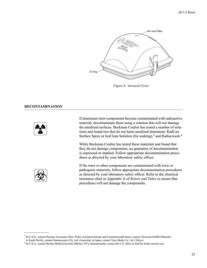
Figure 8. Aeroseal Cover
DECONTAMINATION
If aluminum rotor components become contaminated with radioactive material, decontaminate them using a solution that will not damage the anodized surfaces. Beckman Coulter has tested a number of solu-tions and found two that do not harm anodized aluminum: RadCon Surface Spray or IsoClean Solution (for soaking),3 and Radiacwash.4
While Beckman Coulter has tested these materials and found that they do not damage components, no guarantee of decontamination is expressed or implied. Follow appropriate decontamination proce-dures as directed by your laboratory safety officer.
If the rotor or other components are contaminated with toxic or pathogenic materials, follow appropriate decontamination procedures as directed by your laboratory safety officer. Refer to the chemical resistance chart in Appendix A of Rotors and Tubes to ensure that procedures will not damage the components.
O-ring
Air-vent filter
3 In U.S.A., contact Nuclear Associates (New York); in Eastern Europe and Commonwealth States, contact Victoreen GmbH (Munich); in South Pacific, contact Gammasonics Pty, Ltd. (Australia); in Japan, contact Toyo Medic Co. Ltd. (Tokyo).
4 In U.S.A., contact Biodex Medical Systems (Shirley, NY); internationally, contact the U.S. office to find the dealer nearest you.
23

24
JS-5.3 Rotor
STERILIZATION AND DISINFECTION
• The rotor can be autoclaved at 121°C for up to an hour. Plastic parts can be autoclaved at 121°C for up to 30 minutes. Place the rotor yoke, buckets, and/or microplate carriers in the autoclave upside down.
• The bucket cover, with air-vent filter removed, can be autoclaved at 121°C for up to 30 minutes. Before autoclaving, remove the filter from each cover as described in MAINTENANCE, above. After autoclaving, insert a new air-vent filter into each cover.
• Ethanol (70%)5 or hydrogen peroxide (6%) may be used on all rotor components, including those made of plastic. Bleach (sodium hypochlorite) may be used, but may cause discoloration of anod-ized surfaces. Use the minimum immersion time for each solution, per laboratory standards. Cold sterilization methods such as ethanol (70%), hydrogen peroxide (10%), Wescodyne,6 or Cidex7 may be used on bucket covers. Consult Appendix A in Rotors and Tubes before using any other sterilization methods.
While Beckman Coulter has tested these methods and found that they do not damage the rotor or components, no guarantee of sterility or disinfection is expressed or implied. When sterilization or disinfec-tion is a concern, consult your laboratory safety officer regarding proper methods to use.
STORAGE
When it is not in use, store the rotor in a dry environment (not in the centrifuge).
5 Flammability hazard. Do not use in or near operating centrifuges.6 Registered trademark of West Chemical Products, Inc.7 Registered trademark of Arbrook, Inc. Cidex is a gluteraldehyde (1,5-pentanedial) product.

JS-5.3 Rotor
RETURNING A ROTOR
Before returning a rotor or accessory for any reason, prior permission (a Returned Goods Authorization form) must be obtained from Beckman Coulter, Inc. This RGA form, which may be obtained from your local Beckman Coulter sales office, should contain the following information:
• rotor serial number,
• history of use (approximate frequency of use),
• reason for the return,
• original purchase order number, billing number, and shipping number, if possible,
• name and phone number of the person to be notified upon receipt of the rotor or accessory at the factory, and
• name and phone number of the person to be notified about repair costs, etc.
To protect our personnel, it is the customer’s responsibility to ensure that the parts are free from pathogens and/or radioactivity. Steriliza-tion and decontamination must be done before returning the parts. Smaller items (such as tubes, bottles, etc.) should be enclosed in a sealed plastic bag.
All parts must be accompanied by a note, plainly visible on the out-side of the box or bag, stating that they are safe to handle and that they are not contaminated with pathogens or radioactivity. Failure to attach this notification will result in return or disposal of the items without review of the reported problem.
Use the address label printed on the RGA form when mailing the rotor and/or accessories.
Customers located outside the United States should contact their local Beckman Coulter office.
RGA
25

26
JS-5.3 Rotor
SUPPLY LIST
➠ NOTEPublications referenced in this manual can be obtained by calling Beckman Coulter at 1-800-742-2345 in the United States, or by contacting your local Beckman Coulter office.
Contact Beckman Coulter Sales (1-800-742-2345 in the United States) or your local Beckman Coulter office, or see the Beckman Coulter High Performance, High Speed, High Capacity Rotors, Tubes, and Accessories catalog (BR-8102, available at www.beckmancoulter.com) for detailed information on ordering parts and supplies. For your convenience, a partial list is given below.
REPLACEMENT ROTOR PARTS
JS-5.3 rotor assembly . . . . . . . . . . . . . . . . . . . . . . . . . . . . . . . . . . . . 368690Rotor tie-down knob . . . . . . . . . . . . . . . . . . . . . . . . . . . . . . . . . . . . . 368410Bucket, blue (set of 4) . . . . . . . . . . . . . . . . . . . . . . . . . . . . . . . . . . . . 368706Containment cover set (includes 2 covers with pre-installed
O-rings and air-vent filters, plus 2 each replacement O-ringsand filters) . . . . . . . . . . . . . . . . . . . . . . . . . . . . . . . . . . . . . . . 368417
O-ring replacement set (qty/4) . . . . . . . . . . . . . . . . . . . . . . . . . . . . . 368703Air-vent filter replacement set (qty/60). . . . . . . . . . . . . . . . . . . . . . . 368148Microplate carrier kit. . . . . . . . . . . . . . . . . . . . . . . . . . . . . . . . . . . . . 368914
Contains:Microplate carrier (set of 4) . . . . . . . . . . . . . . . . . . . . . . . . . . . 368905Support pad (set of 4) . . . . . . . . . . . . . . . . . . . . . . . . . . . . . . . . 369382
OTHER
Labware. . . . . . . . . . . . . . . . . . . . . . . . . . . . . . . . . . . . . . .see Tables 1 and 2Replacement tube and bottle adapters (set of 2)
Beige (13 mm dia). . . . . . . . . . . . . . . . . . . . . . . . . . . . . . . . . . . . . 368907Purple (16 mm dia) . . . . . . . . . . . . . . . . . . . . . . . . . . . . . . . . . . . . 368909Red (17 mm dia) . . . . . . . . . . . . . . . . . . . . . . . . . . . . . . . . . . . . . . 368910Yellow (29 mm dia). . . . . . . . . . . . . . . . . . . . . . . . . . . . . . . . . . . . 368911Green (15 mL conical) . . . . . . . . . . . . . . . . . . . . . . . . . . . . . . . . . 368915Black (50 mL conical). . . . . . . . . . . . . . . . . . . . . . . . . . . . . . . . . . 368916Orange (250 mL conical) . . . . . . . . . . . . . . . . . . . . . . . . . . . . . . . 369385Yellow (250 mL round/230 mL conical). . . . . . . . . . . . . . . . . . . . 369383Blue (500 mL conical). . . . . . . . . . . . . . . . . . . . . . . . . . . . . . . . . . 369384

JS-5.3 Rotor
Rubber roller, 4-in., for sealing foil microplate lids . . . . . . . . . . . . . 538618Rotor Cleaning Kit . . . . . . . . . . . . . . . . . . . . . . . . . . . . . . . . . . . . . . 339558Beckman Solution 555 (1 qt) . . . . . . . . . . . . . . . . . . . . . . . . . . . . . . 339555Rotor cleaning brush . . . . . . . . . . . . . . . . . . . . . . . . . . . . . . . . . . . . . 339379Paint On Graphite Lubricant (1/2 oz) . . . . . . . . . . . . . . . . . . . . . . . . . 977212Silicone vacuum grease (1 oz) . . . . . . . . . . . . . . . . . . . . . . . . . . . . . 335148
27


J SERIES SWINGING BUCKET ROTOR WARRANTY
Subject to the conditions specified below and the warrantyclause of the Beckman Coulter, Inc., terms and conditions ofsale in effect at the time of sale, Beckman Coulter, Inc. agreesto correct either by repair, or, at its election, by replacement,any defects of material or workmanship which develop withinseven (7) years after delivery of a J series rotor to the originalbuyer by Beckman Coulter, Inc. or by an authorized represen-tative, provided that investigation and factory inspection byBeckman Coulter discloses that such defect developed undernormal and proper use. Should a Beckman Coulter centrifugebe damaged due to a failure of a rotor covered by this war-ranty, Beckman Coulter will supply free of charge all centri-fuge parts required for repair.
REPLACEMENT
Any product claimed to be defective must, if requested byBeckman Coulter be returned to the factory, transportationcharges prepaid, and will be returned to Buyer with the trans-portation charges collect unless the product is found to bedefective, in which case Beckman Coulter will pay all trans-portation charges.
A defective rotor will be replaced by Beckman Coulter at itsthen current list price less a credit based upon the age of therotor (years since date of purchase). The Buyer shall notreceive credit until the claimed defective rotor is returned toBeckman Coulter’s Indianapolis, Indiana facility or deliveredto a Beckman Coulter Field Service representative.
The replacement price (cost to Buyer) for the respective rotorshall be calculated as follows:
Replacement price = Current rotor list price ×
CONDITIONS
1. Except as otherwise specifically provided herein, this war-ranty covers the rotor only and Beckman Coulter shall notbe liable for damage to accessories or ancillary suppliesincluding but not limited to (i) tubes, (ii) tube caps,(iii) tube adapters, or (iv) tube contents.
2. This warranty is void if the rotor has been subjected tocustomer misuse such as operation or maintenance con-trary to the instructions in the Beckman Coulter rotor orcentrifuge manual.
3. This warranty is void if the rotor is operated with a rotordrive unit or in a centrifuge unmatched to the rotor charac-teristics, or is operated in a Beckman Coulter centrifugethat has been improperly disassembled, repaired, ormodified.
4. Each bucket or carrier, whether purchased with a rotorassembly or purchased separately, is covered by this war-ranty for seven (7) years from the date of purchase, andwill be replaced or repaired during such period accordingto the terms and conditions of this warranty. The date ofmanufacture marked on the bucket may be earlier than thedate of purchase, and the expiration date marked on thebucket, which is seven (7) years after the date of purchase,may be correspondingly offset.
5. Buckets or carriers should not be used after the expirationdate marked on the bucket or carrier. If at the time of pur-chase the marked expiration date is less than 7 years fromthe date of purchase, the expiration date becomes the dateof purchase plus seven (7) years. Use of a bucket or carrierafter such expiration date voids Beckman Coulter’s war-ranty obligations with respect to any rotor and/or centri-fuge in which such a bucket is used.
DISCLAIMER
IT IS EXPRESSLY AGREED THAT THE ABOVE WAR-RANTY SHALL BE IN LIEU OF ALL WARRANTIES OFFITNESS AND OF THE WARRANTY OF MERCHANT-ABILITY AND THAT BECKMAN COULTER, INC.SHALL HAVE NO LIABILITY FOR SPECIAL OR CON-SEQUENTIAL DAMAGES OF ANY KIND WHATSO-EVER ARISING OUT OF THE MANUFACTURE, USE,SALE, HANDLING, REPAIR, MAINTENANCE, ORREPLACEMENT OF THE PRODUCT.
years7
------------


Beckman Coulter, Inc. • 250 S. Kraemer Blvd. • Brea, California 92821Sales and Service: 1-800-742-2345 • Internet: www.beckmancoulter.com
©2009 Beckman Coulter, Inc.All rights reserved