A GUIDE€¦ · · 2012-09-19A GUIDE FOR DESIGN INTEGRATION OF CONCRETE PAVERS ANTON C. HARFMANN,...
63
A GUIDE FOR DESIGN INTEGRATION OF CONCRETE PAVERS ANTON C. HARFMANN, AIA GARY E. DAY, RA CONCRElE PAVmnNSTITUlE 2302 HORSE PEN RQ"i\D HERNDON '-"'>ll ., ., . ..,
Transcript of A GUIDE€¦ · · 2012-09-19A GUIDE FOR DESIGN INTEGRATION OF CONCRETE PAVERS ANTON C. HARFMANN,...

A GUIDE FOR
DESIGN INTEGRATION OF
CONCRETE PAVERS
ANTON C. HARFMANN, AIA
GARY E. DAY, RA
CONCRElE PAVmnNSTITUlE 2302 HORSE PEN RQ"i\D
HERNDON VIRGl!NIA<Z~D7li"3406 '-"'>ll ., ., . ..,

INTRODUCTION
RATIONALE
The ways in which architecture students are introduced to specific pavement material products will determine how successfully that product will be integrated and used in their future design practice. This introduction often occurs,:,s one component of a building science course andjs som"times supported by the manufacturer's assosciation representative with technical notes, handouts and catalogs. In many cases, the information has been prepared primarily for the practicing architect and is therefore quickly filed away and/or discarded by the students along with potential design knowledge hidden within the sales brochures and the detailed technical literature.
The topic of concrete pavers is among the many specific products that students must be introduced to during their architectural education. Unfortunately, the topic typically merits, at best, a mere mention in the construction technology course within a given cuniclum with little relationship to the design studio.
It is the goal of this gnide to improve the design of the paved plane of the built environment by expanding the level of knowledge about concrete pavers. This will be accomplished through the organizing of information and support material for both the instructor and the students. Since an instructor is most familiar with their own course and curriculum, the integration of specific material into an existing course is left in their hands. Furthermore, the varying pedagogical goals makes it difficult to impose a single "static" format of information that forces its way into an existing curriculum or course. The guide is, therefore, meant to be dynamic and flexible and presents information and support material in an accessible format for direct integration within existing design studios, technology courses and other related areas of study.
• I
CONTENTS
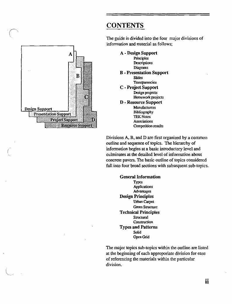
The guide is divided into the four major divisions of information and material as follows;
A - Design Support Principles Descriptions Diagrams
B - Presentation Support Slides Tr.msparencies
C - Project Support Design projects Homework projects
D - Resource Support Manufacturers Bibliography TEKNotes Associations Competition results
Divisions A, B, and D are fIrst organized by a common outline and sequence of topics. The hierarchy of information begins at a basic introductory level and culminates at the detailed level of information about concrete pavers. The basic outline of topics considered fall into four broad sections with subsequent sub-topics.
General Information Types Applications Advantages
Design Principles UIban Carpet
Green Structure Technical Principles
Structural Construction
Types and Patterns Solid Open Grid
The major topics SUb-topics within the outline are listed at the beginning of each approporiate division for ease of referencing the materials within the particular division.
.. II

t-z'"
r-' :ef ="'" "'~ <
GENERALINFORMATION Generictypes
Solid Interlocking OpenGrid
Applicatioos Solid Interlocking
Pedestrian Ugh! Vehicular Indostrial
OpenGrid 0 Vehicular Umdscape
Advantages Design Variety Eovironmen1alImpadt Safety Zip and Unzip Cost
DESIGN PRINCIPLES UIban CaIpet
Mosaics Scale Zoning Marlrers Emphasis Edge
Green Structure GreyJGreenBaiance Distribution
TECHNICAL PRINCIPLES S1ructUIai Principles
ContinuouslContigulllSS Edge RestIaint Five Layers
Cmstructioo.Principles Edge Integr.ilion Insta\Ia1ionMethods
TYPES AND PATi'ERNS Interlocking
Rectangular DenIaIed Denlated2 0ctag00a1 Octagona\2 Lock Tri-l1exagooa\ H-B\ock:
OpenGrid Basicgrid Casle1Jl'Ited
z £ ~ .... .... zo: uo: IH~ ~:;: .., .. 0 .. 0:::> 0:::> .. ., .. ., ~ U
I!I
I!I
<D <D
I
I!I
I I!I I!I
I!I ..
m rn
m
'" u .. 0:",
E:;: ., .. "'::> 0:",
~
-
<D
&
METHOD
The information within each Major division is preceeded by a table of contents listing the order and hierarchy of information. Each section is also cross referenced which facilitates the ability to prepare a lecture, coordinate a project or search for more in-depth information about ~y subJ~t. This cross referencing is achieved by a matrix which occurs at the beginning of each division of information. The matrix intersects general information, design principles, technical principles and patterns with the support matrials needed for preparing lectures, etc.
Following are three examples of how the matrix and table of contents within each section can be used to support the preparation of any given lecture or presentation.
@3>. SEARCH BY TOPIC To find information about a specific topic, the matrix is used in a horizontal method. For example, the specific topic of Advantages of using concrete pavers is found in the general information section of the outline. The matrix is searched horizontally to find the references to basic information about the the topic, slides, transparancies, projects or bibliographic entries.
IIg) SEARCHBYTYPEOFINFORMATION This method of finding information utilizes the matrix vertically. For example, a slide lecture could be prepared by searching down the slide column for intersections with desired topics such as design variety, types and patterns etc.
.&. SEARCH FOR SPECIFIC ITEM If a specific item is desired, it can be located by entering the major division and searching the table of contents within the division for the specific item. For example, a paper written by David Smith could be alphabetically or topically searched for in the resource division.
. .. m

DESIGN SUPPORT
This division of the manual contains the basic design infonnation, descriptions, and diagrams about concrete pavers. Its major emphasis is on the variations and integration of concrete segemental paving into tbe process of design. It is divided into 4 categories of infonnation beginning witb broad overall concepts and culminating with specific design and constuction detailing principles. AU items witbin tbis division (A) are identified by page numbers preceded by tbe letter A. The major topics of information within tbis division include;
GENERAL INFORMA nON Includes a basic description of concrete pavers, a description of the types and advantages for use.
DESIGN PRINCIPLES Includes principles and diagrams for tbe integration of concrete segemental pavers into the design process.
TECHNICAL PRINCIPLES Includes the structural and construction principles and diagrams for integration in tbe design process.
TYPES AND PATTERNS Includes tbe various types of concrete pavers and the specific variations in design for each one.
As outlined in the introduction, tbe items in tbe matrix are cross referenced witb the page numbers in order to facilitate tbe retreival of information. The matrix is shown on the next page witb tbe major topics and subtopics indexed by the appropriate page number.
A-I

Contents , _;i,e ,
,~ 'JENERAL INFORMATION Page A-3 deneric types Page A-4
Solid Interlocking Page A-4 Open Grid Page A-4
Applications Page A-5 Solid Interlocking PedeSIiiin Page A-6 Solid Interlocking Ligll!V'eliicular Page A-7 Solid Interlocking IndBllIi:iiF Page A-8 Open Grid Vehicular Page A-9 Open Grid Landscape Page A-I0
Advantages Page A-ll Design Variety Page A-12 Environmental Impact Page A-13 Safety Page A-14 Zip and Unzip Page A-IS Cost Page A-16
DESIGN PRINCIPLES Page A-17 Urban Carpet Page A-18
Mosaics Page A-20 Scale Page A-22 Zoning Page A-23 Marlcers Page A-24 Emphasis Page A-25 Edges Page A'26
Green Structure Page A-27 Green/Gray Balance Page A-28 Distribution l'aooe A-30
TECHNICAL PRINCIPLES Page A-31 Structural Principles Page A-32
Continuous/Contiguous Page A-33 Edge Restraint Page A-34 Five Layers Page A-35
Construction PrinCiples Page A-37 Edge Integration Page A-38 Installation methods Page A-39
TYPES AND PATTERNS Page A-40 Interlocking Page A-41
RectangUlar Page A-43 Dentated Page A-45 Dentated 2 Page A-46 Octagonal Page A-47 Octagonal 2 Page A-48 Lock Page A-49 Tri-hexagonal Page A-50 I-Block Page A-51
Open Grid Page A-52. Basic grid Page A-53 Castellated Page A-54
A-2
GENERAL INFORMATION
Concrete pavers are individual precast concrete modular units that are assembled to provide larger areas of horizontal surfaces. The units are manufactured from a high strength "zero slump" mix of concrete and they have Qecome a modern alternative to the monolithic scaleless ex~sion of asphalt or concrete pavement
Segmental pavers were historically the dominant method for the surfacing of roads, walks and plazas. The units were primarily bricks or stone and were used successfully for hundreds of years. These surfaces were eventually paved over by the new by-product of the petroleum industry, asphalt The relatively new and inexpensive paving has dominated the paving industry for many years boasting as its primary sales point the low initial cost of installation. However, this single criteria for the selection of paving surfaces has been challenged and certain issues have been raised regarding servicability, lifespan, maintenance cost, aesthetic goals as well as environmental issues.
Concrete pavers are an excellent repsonse to these issues, and they inherit the design character and traditions of the segmental pavers of the past while improving on the strength and servicability of this type of pavement.
This section of information serves as the introduction to the concept of concrete segmental pavers and structures basic information about them in three basic categories;
Generic Types
Applications
Advantages
Design Support· Genera1lnfonnation A-3

Generic Types
By definition, the precast, "unit" nature of concrete pavers results in a non-monolithically paved surface. The basic size of the units is designed so that an individual can place the element by hand. The small units can also be grouped together and mechanically installed.. All precast concrete paving units fall into one of the two
. : following basic categories;
Solid Interlocking Solid interlocking pavers are relatively small in size. They are approximately the size of a brick and are considered the modem day replacement of the brick paver. The units all interlock to form an overall pattern for design purposes and for structural load transmission purposes. The units are traditionally installed over a prepared sub-surface of compacted aggregate and sand with sand in the joints. The sand and vertical surfaces of the pavers utilize shear force between them to transmit loads to a broader base beneath them. The most typical joint is fIlled with sand and ranges from 1/16" to 1/8" (.16mm to .32mm).
However, there are wider joint systems with abutting tabs between the individual units available. These units support the growth of grass in the increases space of the joint.
Open Grid Open grid pavers are much larger in size than the"hand held" size of the solid interlocking pavers. The size typically ranges from IS" to 24" (38cm to 61cm)
on a side, weighing approximately 60 to 80 pounds (27kg to 36kg) each and can be square or rectangular. The units are precast with large cavities or holes through them which form an open grid when installed. These voids allow the immediate penetration of rain water to the earth's surface below thereby reducing runoff and soil erosion. The grid of holes CljIl also support the growth of grass, therfore making their installation a desirable alternative in areas where a large permanently monolithically paved surface is inappropriate.
Design Support - General Information A-4

(
Applications
There are several different applications for the use of segemental concrete pavers. Both the solid interlocking pavers and the open grid pavers can be utilized in the applications, however, each of the two types have more common applications that they are typically associated with. The typical applications are separated by the type of paver and the list belowincludes the applications and some of their specific uses. Following this basic introduction to the various applications, each one will be expanded upon on the subsequent pages. Each of the uses contains design examples and diagrams that illustrate the design variety in their use.
Solid Interlocking Pedestrian
Sidewalks Patios Decks and roof ballast
Vehicular Driveways Roads and parking lots Plazas Service drives/walks
Industrial Airport taxi ways and aprons Loading docks Tenninal Ports
Open Grid Vehicular
ParkinglSemi paved areas Highway shoulders Access ways
Landscape Soil stabilization Erosion control Runoff/Inflltration control
Design Support- General Information A-5
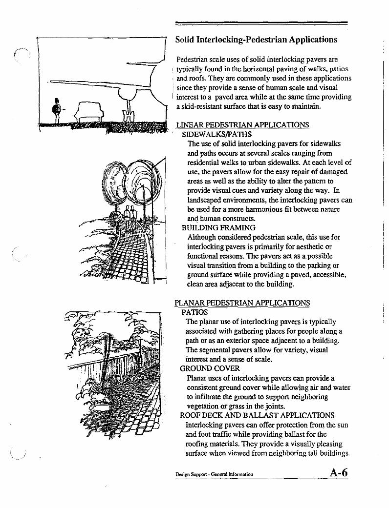
Solid Interlocking-Pedestrian Applications
Pedestrian scale uses of solid interlocking pavers are : typically found in the horizontal paving of walks, patios
and roofs. They are commonly used in these applications since they provide a sense of human scale and visual interest to a paved area while at the same time providing a skid-resistant surface that is easy to maintain.
LINEAR PEDESTRIAN APPLICATIONS SIDEWALKS/pATIIS
The use of solid interlocking pavers for sidewalks and paths occurs at several scales ranging from residential walks to urban sidewalks. At each level of use, the pavers allow for the easy repair of damaged areas as well as the ability to alter the pattern to provide visual cues and variety along the way. In landscaped environments, the interlocking pavers can be used for a more harmonious fit between nature an4 hUman constructs.
BUILDING FRAMING Although considered pedestrian scale, this use for interlocking pavers is primarily for aesthetic or functional reasons. The pavers act as a possible visual transition from a building to the parking or ground surface while providing a paved, accessible, clean area adjacent to the building.
PLANAR PEDESTRIAN APPLICATIONS PATIOS
The planar use of interlocking pavers is typically associated with gathering places for people along a path or as an exterior space adjacent to a building. The segmental pavers allow for variety, visual interest and a sense of scale.
GROUND COVER Planar uses of interlocking pavers can provide a consistent ground cover while allowing air and water to infIltrate the ground to support neighboring vegetation or grass in the joints.
ROOF DECK AND BALLAST APPLICATIONS Interlocking pavers can offer protection from the sun and foot traffic while providing ballast for the roofing materials. They provide a visually pleasing surface when viewed from neighboring tall buildings.
Design Support - General Information A-6

Solid Interlocking-Vehicular Applications
The ability of interlocking pavers to disperse and transfer vertical loads to the ground allows for their use as pavement for intermediate loads and vehicular use. The primary applications for medium scale use include driveways, roads and plazas. The segmental nature of the pavers allows for easy repair and addition of underground services at a later date. The larger scale use also provides opportunities for large scale mosaics and design patterns that suggest zones of use and provide visual cues to the built environment
LINEAR VEHICULAR APPLICATIONS DRIVEWAYS AND ROADS
A primary medium scale use of solid interlocking pavers is for drives and roads. They can provide an elegant paved surface that can also double as a sidewalk in areas where a monolithic permanent drive is inappropriate. The medium scale use of these pavers can also be combined with pedestrian activities in areas where space is limited. An example of this is the "verkersbehrurgung", a combination of street and pedestrian walk/play areas. Another example of this is the use of a sidewalk as an occasional service drive to a building.
PLANAR VEIDCULAR APPLICATIONS PLAZAS
Another application of solid interlocking pavers is for the horizontal surfacing of courtyards and plazas. The variety of patterns, colors and sizes can be incorporated in an overall design concept that reinforces a building or landscape. The designs can take many forms including mosaic murals or scale versions of city blocks. The altering of shape, pattern and color can also indicate different uses on a large otherwise monolothic, bland surface.
Design Support - Generallnformation A-7

Solid Interlocking-Industrial Applications
The individual unit strength of a solid paving unit allows it to be used for industrial applications. Given the proper sub-grade earth, sub-base and base preparation, interlocking pavers are capable of dispersing and transfering heavy vertical loads to the ground. This ability makes them suitable for use in heavy duty applications as an alternative to monolithic pavement systems. The high load bearing capacity and the ease of repair and maintenance makes them a viable long term pavement alternative. In very large scale applications, grid pavers offer much more runoff infIltration which inturn reduces the need for major storm water management systems and retention.
I LINEAR INDUSTRIAL APPLICATIONS I TAXI WAYS, APRONS AND LOADING DOCKS
The segmental paving for taxi ways and loading docks provides a safe, skid-resistant surface that can be easily repaired when the ground below settles under extreme industrial load conditions. Unlike monolithic paving that cracks under deformation, the solid interlocking pavers can move freely, minimizing cracking. Any settling can be corrected by removing the units in the affected area, restoring the base, and then replacing the units.
PLANAR INDUSTRIAL APPLICATIONS TERMINAL AND PORT APPLICATIONS
For extremely large scale horizontal heavy applications, the unit pavers provide a visual reduction in scale and respond very well to the wheel loadings of heavy industrial uses. These wheel loads can be as much as 10 times that of normal street loads which could cause deformation of an ashpalt surface. The repetitive nature of these loads has' also been known to crack or crush monolithic concrete surfaces. In a segmetally paved area, however, these problems can easily be repaired.
Design Support • General Information A-S

Open Grid-Vehicular Applications
The installation of the open grid paving units can be in a linear or planar arrangement. Because they are larger in size with open cells, they will support the growth of grass through them from below as well as allowing for light, air and water to pass through them from above. These characteristics make them the prime choice for paving where the visual impact of a monolithically paved surface is inappropriate and there is a need to support vegetation and reduce storm water runoff and its affects.
LINEAR VEHICULAR APPLICATIONS ACCESS APPLICATIONS
Open grid pavers are frequently used for access roads where the construction of a solid and monolithic surface might be inconsistent with the building design and/or where air and water must be absorbed through the pavement to support existing vegetation. Due to the varied surface of these paving units, they have a tendancy to reduce vehicular speed. Typical installations include access roads, boat launching ramps and fIre/maintenance lanes adjacent to buildings.
SHOULDER APPLICATIONS Open Grid pavers can be used in combination with solid paving as a shoulder to runways, taxiways, highways or roads. This application reduces the amount of runoff on large paved surfaces, provides a visual separation of the main vehicular surface from the shoulder, and can alert a driver or pilot to the edge due to the change in the surface.
PLANAR APPLICATIONS PARKING
The most common vehicular use of open grid pavers is for traditional or overflow parking. In large paved areas, the use of open grid pavers will reduce runoff, reduce the temperature of a parking area and provide for a more visually stimulating surface. As overflow parking, an area surfaced with open grid pavers will have the same basic characteristics and will be less obtrusive than a solidly paved surface when not in use.
Design Support - Generallnformation A-9

Open Grid-Landscape Applications
The use of open grid pavers as part of the landscape vocabulary is primarily for sensitive integration with the environment. The open nature of these pavers allows for the penetration of air and water thereby supporting the growth of vegetation while stabilizing the soil at the same time. Although the major use of these pavers is in a planar arrangement, there are linear uses that integrate open grid pavement in a landscape environment.
LINEAR LANDSCAPE APPLICATIONS GARDEN PATHWAYS
Open grid pavers can provide a firm visualy integrated path through a garden while supporting the need for water and air to reach the roots of the plants. Since the pavers themselves will support the growth of grass within their cells. there will be less solid paving exposed therefore reducing visual inconsistencies. temperature. and runoff.
NATURE TRAILS In a natural environment. open grid pavers can provide a path that minimizes visual intrusion while t----- - : at the same time provides a low maintenance. firm surface through the landscape.
PLANAR LANDSCAPE APPLICATIONS SOIL STABILIZATION
The interlocking nature of open grid pavers allows for their use over poor soils in order to provide a firm surface. Since they are segmental, any base settlement can easily be repaired by removal of one or several units.
EROSION CONTROL For steep slopes that are subject to erosion. open grid pavers provide stabilization to the earth below by introducing a surface above with a course texture. This rough surface reduces the velocity of the runoff and is not subject to erosion. Since the pavers are interlocked or stacked on a slope. they will also-be forced to remain in the planar arrangement in which they were placed. The support of vegetation in the open cells also minimizes visual intrusion.
Design Support· Generallnforrnatioo A-lO
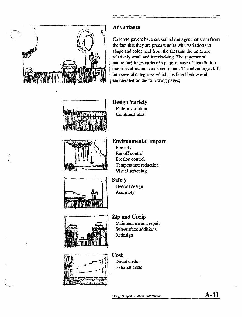
Advantages
Concrete pavers have several advantages that stem from the fact that they are precast units with variations in shape and color and from the fact that the units are relatively small and interlocking. The segemental nature facilitates variety in pattern, ease of installation
i\ and ease of maintenance and repair. The advantages fall into several categories which are listed below and enumerated on the following pages;
Design Variety Pattern variation Combined uses
Environmental Impact Porosity Runoff control Erosion control Temperature reduction Visual softening
Safety Overall design Assembly
Zip and Unzip Maintenance and repair Sub-surface additions Redesign
Cost Direct costs External costs
Design Support - Generallnfonnation A-U

(
Design Variety
The variety in shape, size and color of segemental precast concrete pavers results in many design opportunities. The units by default result in a visually stimulating surface that can vary in scale, colors, patterns and can be combined in various ways in order to emphasize or mark certain aspects of a design. Variety can be achieved in several ways including;
PATTERN Many of the unit shapes can be combined in various patterns to suggest movement, emphasize a design element or suggest different zones of use. The small size and easy manipulation of the units also supports the possibility of constructing large scale mosaics.
COLOR Units can vary in color within a design in order to provide visual cues for different uses or to alter the scale of a very large horizontally paved area. Since the units are colored throughout, they will never need to be "repainted".
COMBINED USES Additional design variety is possible by combining various basic unit shapes and colors to provide a surface that varies in scale as well as function. The variation in pattern can suggest zones of use as well as support a transition in scale from one area to another.
Design Support - Generallnfonnation A-12

Environmental Impact
The non-monolithic surface of precast concrete pavers allows them to minimize the impact on the local environment Where a paved surface is necessary, the segmental pavers can be integrated with the functions of the earth and environmental conditions thereby reducing the overall impact that a monolithic surface might impose.
POROSITY The natural porosity of concrete pavers, occuring in the joints of solid unit pavers and in the cells of open grid pavers, supports the transmission of air and water to the roots of trees or any nearby vegetation. The absorbtion rate for segmental paving varies with joint size and material but in most cases is superior to many other paved surfaces.
RUNOFF CONTROL When spaced apart the individual paving units combined with the sand base on which they are typically installed allows them to absorb a significant amount of stormwater runoff. The percentage of water that runs off of a concrete paver surface is only sJighly higher than that of a grassy area but less than half that of a solid, monolithically paved surface.
EROSION CONTROL The slight irregularity and undulating texture provided by segmental paving can reduce the velocity of runoff thereby reducing the potential erosion of the earth below.
TEMPERATURE REDUCTION The abilty of open grid pavers to support the growth of grass results in a surface that is more able to absorb and reduce solar radiation. The net result is a reduction in the temperature over other pavements.
VISUAL SOFfENING The many joints and variations in pattern, color and shapes results in a more visually stimulating "softer" horizontal surface.
Des.ign support' - Generallnformation A-13

(
Safety
The surface provided by precast concrete pavers is a naturally safe surface for both vehicular and pedestrian ' traffic usage. The variety in pattern and color can also define different zones of use that might separate vehicular traffic from pedestrian traffic. The safety issues are therfore separated into two distict categories that deal with safety at two different scales.
OVERALL DESIGN TEXTURE
The many number of joints in concrete pavers results in a surface that has considerable texture. The somewhat noticable sound and feel of vehicular movement over this type of surface has the natural tendency to slow traffic. This makes the use of this type of paving ideal for mixed pedestrian/vehicular applications.
PATTERN The variation in pattern and the use of markers within the paving to dilineate between two different types of functions such as fast moving pedestrian traffic from slower moving pedestrian traffic.
ASSEMBLY SURFACE FRICTION
The overall assembly of individual units with many joints is by nature skid-resistant The surface of the individual unit has been shown to have a skid-
. resistance similar to asphalt pavements. i WATER DISPERSAL
The fact that water is easily channeled into the chamfers of segmental pavers reduces the formation of water puddles that may cause a slippery pedestrian surface. The chamfers eliminate the potential of hyroplaning or loss of control of vehicles on the slick surface.
Design Support - General Infonnation A-14

-
Zip and Unzip
The indivual units of interlocking concrete pavements suppon the concept of a "zipper" which can be undone and then redone in a simple manner. Since the pavers are interlocked and not pennanently attached to one another, it is possible to remove several individual units and simply replace them once a repair is made. The final result is undetectable and inexpensive. It is an immediate response to the need to gain access to the surface below or for the repair of damaged areas of the surface. The types of applications for the "zip-unzip" principle are expanded upon below.
MAINTENANCE AND REPAIR There are several ways in which a segmentally paved surface can be damaged._Most of the types of damage can be classified as either individual unit failure, as would be the case in the breaking of a unit under heavy loads, or overall base suppon failure, that might occur from the local settling of an area under the paved surface. In both cases, repair andmaintenance can be accomplished by removal of individual units, repairing the subsurface support and replacing the existing units. Broken units are simply replaced indiviually.
SUBSURFACE ADDITIONS The zip-unzip principle can be applied in the event that additional services are required below the paved surface. This facilitates the addition as well as the repair of the subsurface system while preserving the pavement system. In many horizontally paved applications, this technique eliminates the need to repave the entire surface once the alteration is made.
REDESIGN' An existing area of segmental pavers can be redesigned by employing the zip-unzip concept This redesign can be in response to the need to support heavier loads in pan of the paved area or simply to create a different pattern that is pan of an overall redesign effort.
Design Supporr • General Information A-1S
ASPHALT
PAVEI\~E
(Comp~)
PAVERS
End of SeJVice
Life
CONSTA~T~GVER~
Initial. cost varies with applicatiOn
I
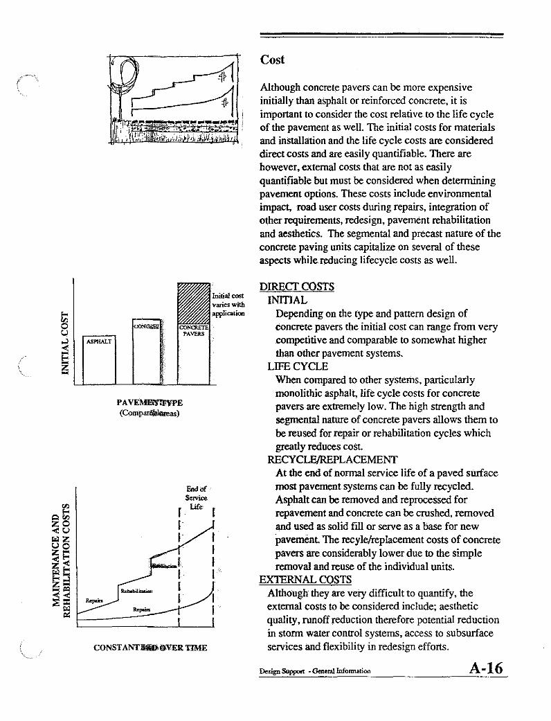
Cost
Although concrete pavers can be more expensive initially than asphalt or reinforced concrete, it is important to consider the cost relative to the life cycle of the pavement as well. The initial costs for materials and installation and the life cycle costs are considered direct costs and are easily quantifiable. There are however, external costs that are not as easily quantifiable but must be considered when detennining pavement options. These costs include environmental impact, road user costs during repairs, integration of other requirements, redesign, pavement rehabilitation and aesthetics. The segmental and precast nature of the concrete paving units capitalize on several of these aspects while reducing lifecycle costs as well.
DIRECf COSTS INITIAL
Depending on the type and pattern design of concrete pavers the initial cost can range from very competitive and comparable to somewhat higher than other pavement systems.
LIFE CYCLE When compared to other systems, particularly monolithic asphalt, life cycle costs for concrete pavers are extremely low. The high strength and segmental nature of concrete pavers allows them to be reused for repair or rehabilitation cycles which greatly reduces cost. RECYC~PLACEMENT
At the end of normal service life of a paved surface most pavement systems can be fully recycled. Asphalt can be removed and reprocessed for repavement and concrete can be crushed, removed and used as solid fill or serve as a base for new pavement. The recyle/replacement costs of concrete pavers are considerably lower due to the simple removal and reuse of the individual units.
EXTERNAL COSTS Although they are very difficult to quantify, the external costs to be considered include; aesthetic quality, runoff reduction therefore potential reduction in storm water control systems, access to subsurface services and flexibility in redesign efforts.
Design Support - General Infonnation A-16

DESIGN PRINCIPLES
The common misconception about the topic of paving is that it is exclusively used for parking lots. In this section, two new concepts are introduced that redefine the way in which paving is viewed. The two major sections stimulate and promote thinking about the exteri()r horizontal surfaces in a non-traditional way and presents diagrams and illustrations that integrate the use of precast concrete pavers into the design of the built environment. The two major sections include;
Urban Carpet
Green Structure
At first reading, these terms seem to be oxymorons. Most design discussions typically focus on urban structures and green carpet therefore isolating them from one another. The juxtaposition of these two terms is intended to pose an alternative way for horizontal surfaces to be perceived. It is an effon to stimulate the thought process and present design issues that can be integrated during the overall design process.
The two sections and most of the principles within are presented as interdependant, parallel concepts that can be applied in design at both the individual paver scale as well as the overall city scale.
A-17

! I, ,
Urban Carpet
The term Urban Carpet forces the designer to reconsider the quality of the vast floor of cities, towns and urban environments. It elevates the awareness that the ground plane of these built environments are the principal surfaces with which that humans have contact The Urban Carpet is a reconceptualization of the exterior paving surfaces and attempts to recast the design of these surfaces as an equal one of three planes that can be used to define and create volume and place.
The design vocabulary of the Urban Carpet is consistent with that of building design, neighborhood design and urban design. At the urban design scale, the principles parallel the cognitive mapping work of Kevin Lynch. The concentration of this section will therefore be placed on the paver scale of design but the reader should allow for these principles to ''jump'' scale to the site, neighborhood or city scale to achieve the greatest integration. The major topics for design consideration at the paver scale are listed below.
Mosaics" Includes the use of segmental paving for creation of the "urban carpet"
Scale,' Includes the use of segemental paving to alter, transform Or suggest scale in a large paved environment
Zoning' Includes the use of segmental paving to suggest different zones of use or spatial orientations.
Design Support - Design Principles A-1S

".
Markers Includes the use of segmental paving to identify specific activities, areas of use or for provinding visual cues to the environment.
Emphasis Includes h use of segmental paving to develop a focus or emphasize a design element.
Edge Includes the design options for the edges of segmentally paved surfaces.
Design Support - Design Principles A-19

;
~1ll . t .. ..
Mosaics
The concept of an urban carpet is most obviuosl y expressed through the use of segmental pavers to create a large scale mosaic. Mosaics integrated in the paving of exterior surfaces can serve several functions that go beyond simple decoration. They can provide visual cues to the environment, lend a sense of scale to a large area, suggest movement or emphasize an aspect of an overall design concept The most commonly used urban carpet mosaics can be classified as either geometric patterns or pictorial patterns.
GEOMElRIC PATTERNS
GRIDS Grids are used to alter the scale of a very large scale paved area. They can suggest quadrants of use as well as providing visual cues to different activites .
CENTERED A centered pattern typically incorporates a border and a focal point In design terms it is most similar to an oriental carpet It can be used to emphasize or focus on a design element
LINEAR Linear patterns can be used to suggest direction, separate parallel activities or mark subsurface utility lines or services.
Design Support· Design Principles A-20
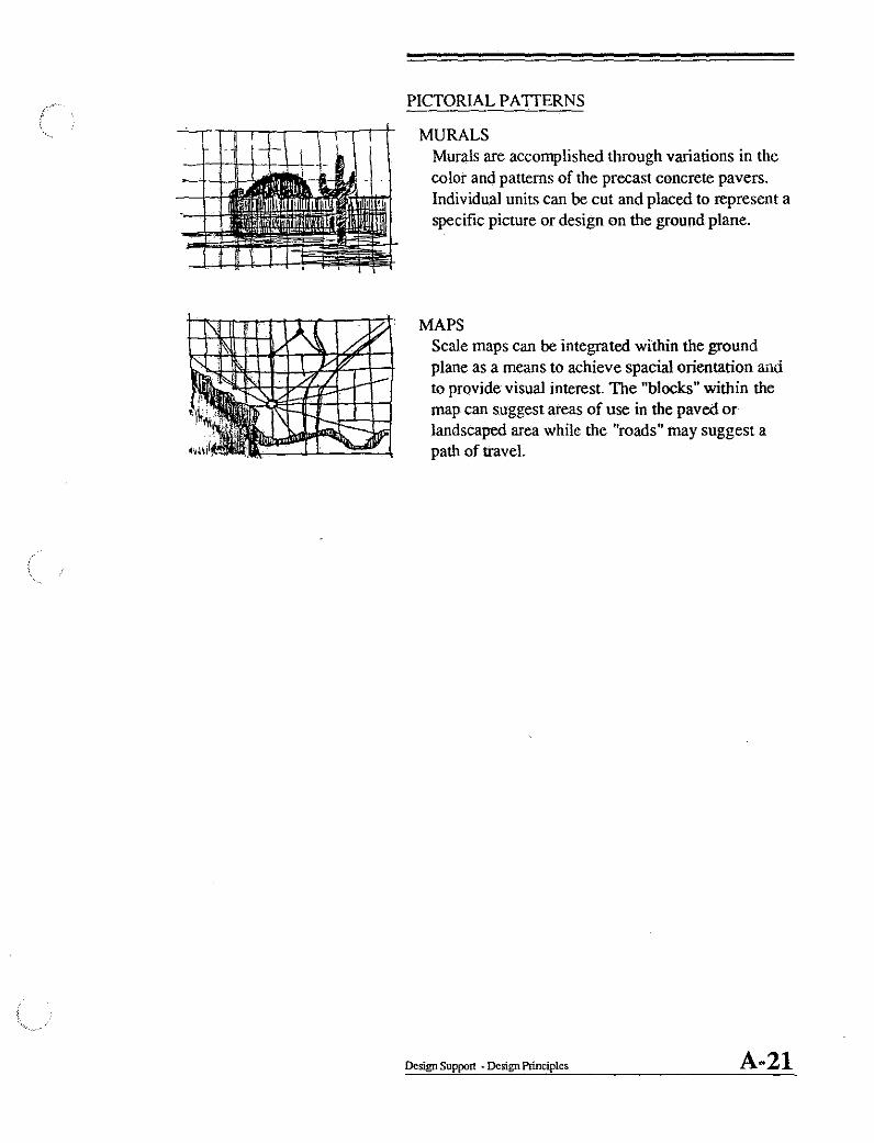
PICTORIAL PATTERNS
MURALS Murals are accomplished through variations in the color and patterns of the precast concrete pavers. Individual units can be cut and placed to represent a specific picture or design on the ground plane.
MAPS Scale maps can be integrated within the ground plane as a means to achieve spacial orientation arld to provide visual interest. The "blocks" within the map can suggest areas of use in the paved or landscaped area while the "roads" may suggest a path of travel.
Design Support - Design Principles A-21
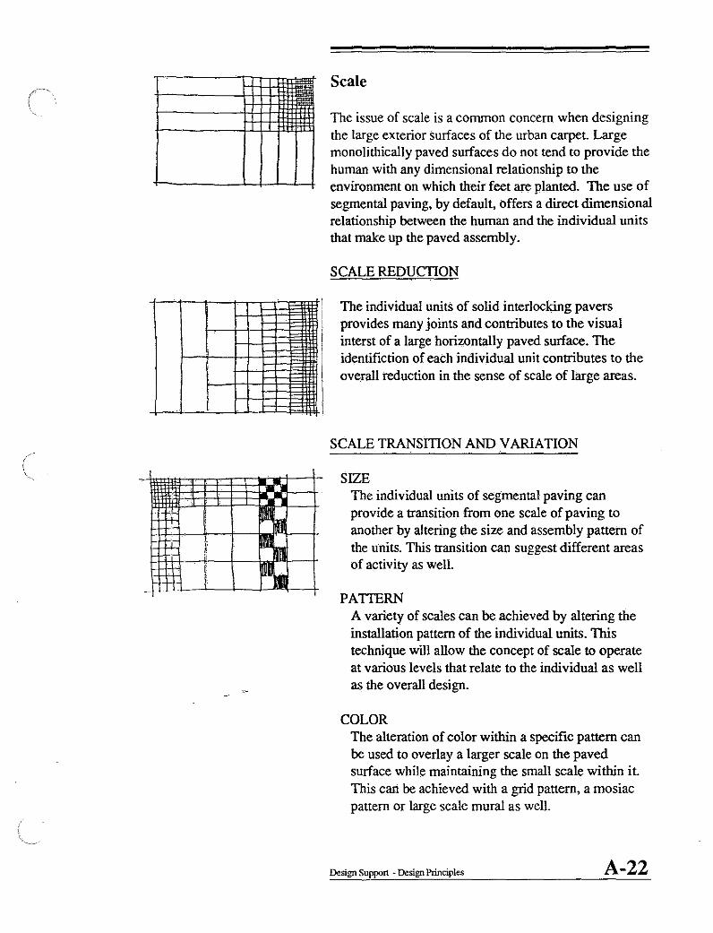
I Scale
The issue of scale is a common concern when designing the large exterior surfaces of the urban carpet. Large monolithically paved surfaces do not tend to provide the human with any dimensional relationship to the environment on which their feet are planted. The use of segmental paving, by default, offers a direct dimensional relationship between the human and the individual units that make up the paved assembly.
SCALE REDUCTION
The individual units of solid interlocking pavers provides many joints and contributes to the visual interst of a large horizontally paved surface. The identifiction of each individual unit contributes to the overall reduction in the sense of scale of large areas.
SCALE TRANSmON AND V ARIA nON
SIZE The individual units of segmental paving can provide a transition from one scale of paving to another by altering the size and assembly pattern of the units. This transition can suggest different areas of activity as well.
PATTERN A variety of scales can be achieved by altering the installation pattern of the individual units. This technique will allow the concept of scale to operate at various levels that relate to the individual as well as the overall design.
COLOR The alteration of color within a specific pattern can be used to overlay a larger scale on the paved surface while maintaining the small scale within it. This can be achieved with a grid pattern, a mosiac pattern or large scale mural as well.
Design Support· Design Principles A-22

Zoning
The combinations of various patterns and colors of concrete pavers can be used to suggest different zones of use or activity. This is of particular importance when the uses are a mix of pedestrian and vehicular. Different zones can be delineated using a variety of different patterns and colors. Segmental pavers can also be combined with traditional paving to achieve the same separation between activities or design elements.
TRAFFIC ZONING PEDESTRIAN-PEDESTRIAN
This linear application of zoning is typically associated with busy sidewalks that are used for major travel routes and window shopping at the same time. A smaller pattern of pavers or pavers of different color can be utilized to separate the fast moving pedestrian traffic from the slow moving window shopping pedestrians.
PEDESTRIAN-VEHICULAR Vehicular traffic can be separated from slow moving pedestrian traffic by introducing a zone of pavers between the sidewalk and the road. This zone can be integrated with landscaping to increase safety and separation. Safety can also be enhanced by utilizing segmental paving units for the road surface. This will have the effect of reducing traffic speed next to the sidewalk.
VEHICULAR-SHOULDER SegllJental paving can delineate between a the main surface of a road and the shoulder of the road. The change in texture provides for a visual cue to the edge of the road as well as a tactile cue along the road's edge.
ACTIVITY ZONING PEDESTRIAN-STRUCTURE
Concrete pavers can be used to provide a separation between a structure and a sidewalk. This technique maintains a clean, maintenance free visually stimulating surface adjacent to a structure that can be applied to a slope as well.
Design Support - Design Principles A-23

,~.
. /
__ J, /_
~. -' ,/
\
Markers
The use of individual units assembled to provide a continuous paved surface allows for the change in pattern or color of an individual unit or a group of units. This change can be integrated with the need to mark certain important features or as a technique that supports the delineation of zones between one activity and another. The markers can be used for visual cues between activities or for indicating the location of subsurface utilities.
BOUNDARY Colored units can be integrated with natural units to indicate the separation of one area from another. Examples of this include the marking of parking spots and the marking of the edge between one zone of activity and another. Markers can also be utilized as borders or edge conditions separating the paved surface from the unpaved surface.
LINE OF TRAVEL A change of color or pattern in the paving units can indicate a line or path of travel. For example, this can be used to indicate lanes in a road or the shoulders of an airport taxi way.
SUBSURFACE MARKERS The location of subsurface utilities can be identified by markers designed in the pattern of the paved surface. For service of the utilities below, only the "marked" units need to be removed to gain access. The indication of these linear utilities can be combined with other desgin principles such as zoning and scale in order tl;) conceal the purpose of marking the subsurface activities.
SPECIAL PLACE Markers can be incorporated to indicate a special point or place within a paved surface such as a benchmark, milestone or monument.
Design Support - Design Principles A-24

Emphasis
The use of segmetnal pavers can be used to emphasize a specific design element By interupting an existing
i pattern with pavers of a different size, type, color or , pattern, a specific part of the design can be framed or
+-----------1, contrasted in order to highlight its importance or significance.
PATfERN The particular pattern selected can emphasize a design element Typically, a concentric square or round pattern can make the centered element a focal point within the overall pattern.
COLOR Varying the color within a pattern can be utilized to highlight an area, separate one area from another or indicate a significant line in the paved surface.
FRAME By framing an object or design element, the basic pattern of the pavers may be interupted. This interuption and change in the pattern around the object will further emphasize its importance.
Design Support ~ Design Principles A-25

Edges
As with any carpet, the edge or boundry condition demands special consideration. The edges considered include the conditions between paved and unpaved surfaces as well as the interface between two different paving patterns. In either case, the individual units can be integrated with the edge or cut to follow the edge.
PAVED TO NON-PAVED INTEGRATED
An integrated paved edge against a non-paved area allows each unit to maintain its integrity. This tpye of edge uses only full or special unts and the border is forced to follow the shape of the pavers. This edge condition can be either free, allowing the pavers to undualate within the curb or non paved area, or controlled with the use of half or special pavers manufactured as part of the pallette of units.
INTERUPTED Interupted paved to non-paved edges indicates a condition where the shape of the edge dominates the integrity of individual pavers. In this scenario, pavers are cut or interupted to follow an edge condition.
PAVED TO PAVED INTEGRATED
An integrated edge between two patterns maintains the integrity of each individual paver. The pattern undergoes a deformation without the cutting of a unit. This can be accomplished most successfully with the traditional shaped units.
INTERUPTED When it is not possible to integrate two different patterns or when the design calIs for the domination of one pattern edge over another, the individual units must be cut and the pattern interupted. This technique will emphasize one pattern's edge over another.'
Design Support· Design Principles A-26

Ir=i \
.~ ... ~£. ilil\--r ~UjJ.i ....
:~., ~~ ... - j .~
(
Green Structure
The term Green Structure is borrowed from the European planning model that links the natural "green" qualities of the environment with the organizing human "structure" of an urban or landscape design. The use of this concept can be applied to both urban and natural environments. In the urban environments, it promotes the view of the green component as an equal to the other built systems of the urban infrastructure such as roads, utilities and bUildings. The green structure is a mechanism to control or maintain the natural environment when intervention or urbanization has caused an imbalance.
The green structure urban design principles are structured within two topics that are listed below;
Gray-Green Balance Presents ratio guidelines and approaches for succesful horizontal and vertical integration of green into sites, neighborhoods, and urban structures.
Distribution Presents guidelines for distribution and variety of green within the horizontal plane of pavers.
Design support - Design Principles A-27

(
Gray/Green Balance
The gray/green balance focuses on the ratio and layering of the natural green within the human constructed, gray, urban environment. The amount of green in plan and the proper placement and development of the layers of green in section are critical for the proper growth and harmonic support of the plant materials. The benefits of the green structure include temperature reduction, runoff control, visual appeal and as a whole has been described as the "lung" of the city when properly designed and integrated. The basic principles of the gray/green balance concentrate on the integration of green at the site or paver scale, however, they can be utilized at the design scale of the neighborhood and city as well. The basic principles inClude;
THE 60/40 RATIO This describes the desired ratio of gray to green of the built environment (60 percent gray and 40 percent green), and applies to all scales of design. It can be applied to all horizontal andlor vertical surfaces of the urban fabric. The rule attempts to insure enough overall green within the urban structure to provide mutual support of plant life and the realization of the environmental benefits.
INTERUPTED Green can be incorporated in the gray horizontal surface by interupting the pavers with points or lines of green. At the urban and neighborhood scale, point elements include parks, fields and playgrounds while line elements include continuous lawn areas, tree lined boulevards and medians. At the paver scale point or line interuptions are individual plantings such as trees or bushes. The paved surface and function is interupted to allow the introduction of a green element.
INTEGRATED The integrated approach utilizes open grid pavers or widely spaced solid pavers for the support of green within the paved plane. The 40% of green exists within the same plane as the gray and therefore does not interupt the function of the horizontal surface but is obviously limited to ground cover scale green
elements for achieving the balance.
Design Support - Design Principles A-28

THE FIVE LAYER APPROACH The five layer approach is a sectional response to the placement of green in the urban structure. The principle of providing five layers of green serves to improve the development of the vegetation and increases the sense of
: visual appeal and integration of the green. The layers , include;
CANOPY, mature, full height, trees. UNDERSTORY, immature or shorter species of trees. SHRUBS, bushes and shrubs. GROUND COVER, grass, ivy or other ground cover. FLOOR, access of water and air to roots below.
Since the floor in the urban environment is typically paved, its treatment becomes a critical concern for the support of the layers above it. As a rule of thumb, it is desirable to provide as many of the five layers as possible and maximize the penetration of air and water to the root structure of the green below the paved surface. The principles concentrate on the design of green when it interupts the paved surface and when it is integrated with the paved surface.
INTERUPTED When green structures interupt a continuously paved horizontal surface, the correct amount of porosity below a green structure can be achieved by providing 40% of the area under the dripline as earth or ground cover. This can be accopmplished with a grate, open grid pavers or any 60/40 combination of green! gray under the dripline.
\
INTEGRA TED When green ground cover is integrated with the pavers it can provide a vast area of visual green while also supporting other layers above. In driving lanes, grass should be placed in the units between the tires. In parking areas, green can be used throughout but it is recommended that solid pavers be used under the engine area and between cars.
Design Support· Design Principles A-29

(
Distribution
This principle centers about the distribution and variety of the green within the gray/green balance. The concept suggests that there must be some variety in the green and that the green must be distributed at the various scales of implementation of city, neigborhood, and site. This allows the density of 60/40 to be varied across the application and insures the benefits of the green structure throughout. The basic principles for successful integration of the green structure include the following;
CONTINUOUS/CONTIGUOUS The green should be distributed throughout the urban, neighborhood or site fabric. Concentration of the entire 40 percent of green in one will deny the environmental and visual benefits of the green from the other portions. The distribution should also attempt to be contiguous so that the green effects and mutual support can spread from one green area to another.
V ARJETY /DIVERSITY In order to avoid the possibility of losing the green structure it is important to distrubute different varieties of vegetation throughout. The rule of thumb suggests that there should not be more than 15 percent of anyone variety of planting. The distribution of the various plant material should also be fairly even across the urban fabric. This will insure overall continuous disrtibution and general density should one variety perish.
Design Support • Design Principles A-30

TECHNICAL PRINCIPLES
The technical infonnation designers often recieve is far too detailed for the preliminary stages of design. At the early stages of a design project, the technical infonnation sought is typically general in nature and does not need to focus on the specific analysis or engineering of the assembly. This section therefore focuses on some of the basic principles that are necessary during the conceptual and schematic design phases of a project. The detailed infonnation about individual units can be found in the next section on TYPES AND PA ITERNS and information on the engineering of the assemblies and specific installation techniques can be found in the RESOURCES division.
The technical principles in this section fall into two categories of infonnation that focus on the structural principles and behaviors of pavers and the details for installation of pavers. The sections are accordingly;
Structural Principles
Construction Principles
DesignSupport • Teclmical Principles A-31

Structural Principles
The successful transferral of any vertical load through a I segmentally paved area requires the incorporation of ,
three principles. These principles must be utilized when installing open grid as well as solid interlocking pavers. It is also important to note that all three principles in this section are equally important, however, they have been described in a hierarchy that is sensitive to the design process.
Continuous/Contiguous Describes the necessity of the pavers to be adjacent to each other for successful load transferral.
Edge Restraint Descrides the need to contain the paved area for the proper development of horizontal forces.
Five Layers Describes the preparation of the base for the various load applications.
Design Support . Technical Principles A-32

\
Continuous/Contiguous
Vertical loads are transferred through an assembly of units throught the development shear between the units. When the units are placed next to each other in a tight arrangement, friction between the units is developed thereby mobilizing a large portion of the paved plane for load resistance. In order to develop the friction which develops the shear, the units must be continuous and contiguous within an arrangement. The interlocking nature of the concrete pavers by default results in a continuous and contiguous assembly. however. it is good practice to follow the two basic rules below when designing a segmentally paved surface;
CONTINUITY OF FACES At a minimum. the two opposite faces of a surface of concrete pavers must be contiguous. This will result in load transferring in basically one direction and is acceptable for linear arrangements under light loading conditions. For higher load carrying capacity. continuity in more than one direction is necessary. This arrangement will transfer loads to all of the neighboring units much like a space frame building system.
DISCONTINUITY OF LINES OF ACTION COMPLEXITY IN PATrERN DESIGN
Mobilization of large areas of the paved surface under load is directly related to the ability of the individual unit under load to transfer the shear to as many neighboring units as possible. Discontinuity of lines of structural action can be continually transfered from a unit in one direction to a unit in another direction through complexity in the laying pattern, such as 90 or 45 degree herringbone.
COMPLEXITY IN UNIT DESIGN Increased shear and discontinuity of action lines can also be achieved through a complex interlocking shape. such as the dentated unit. The complex shaped units offer several paths for loads to travel thereby involving a large paved area for resisting loads.
Design Support . Tectmical Principles A-33

Edge Restraint
In order to develop the friction between neighboring units, the units within a paved surface must be restrained from drifting away from one another. This is accomplished through the use of edge restraints that keep the pavers in a contiguous arrangement. It is ideal to have all of the edges of a paved surface restrained as this will result in load transferring in more than a single direction. The restaint can occur in a variety of ways and will fall under one of the following generic types;
PAVED TO UNPAVED To develop sufficient restraint at an unpaved border, the edge must penetrate the earth to a depth that will force the adjacent ground to act as a berm. This is typically accomplished through the use of a curb of pavers on end, a continuous metal strip or a continuous, poured concrete strip.
PAVED TO PAVED AT DIFFERENT LEVELS In this scenario, the force offered by the edge restraining must be transferred from one level to another. This is best accomplished through a gentle curving of the units from one level to another or the use of a curb for abrupt changes in level. The curb for the abrupt changes must be stiff enough and deep enough to resist any rotation due to the lateral forces induced by the adjacent paved surface at different levels.
PAVED TO BUILDING MASS When paving up to a building, edge restraint occurs naturally at the vertical walls of the building. At this junction; pavers must conform to' the shape of the building at the pavement level and the lateral force developed within the plane of the paved surface will be resisted by the building mass.
Design Support • Technical Principles A-34

Five Layers
The preparation of the base is the final element in the succesfulload carrying capacity of concrete pavers. Although this is not a visible "design" element it is an important general principle that must be considered during initial conceptual design phases. The previous two principles deal primarily with the surface layer
I which is the top layer of the five total The remaining four exist below the surface of the pavers.
PAVED SURFACE Sand or spacers between units to develop shear (friction) between units.
SAND BASE Leveling bed, even distribution of load to base through the use of a consistent, level surface.
BASE Leveling and distribution of load to subbase. Smaller particles prevent the sand from seeping into it Base materials are compacted to increased their load bearing capacity.
SUB-BASE Well compacted and sometimes made of larger aggregate for overall stability on soft wet soils. Depth depends on quality of soil and load bearing capacity. Sometimes the sub-base is omitted and its absence is compensated by a thickened base.
SUB-GRADE EARTH The natural load bearing capacity of the existing earth at the site must be sufficient to endure the loads placed upon the pavement, sand and base. The subgrade earth is often compacted prior to the installation of the layers above. For weaker soils, the stronger base and sub-base materials disperse the loads across the soil to minimize deformation.
Design Support - Technical Principles A-35

PEDESTRIAN OR LIGHT VEHICULAR LOADS For light loads on normal soils, the cross section of the layers are proportioned as I: 1/2: I: I. That is; the unit thickness at the paver level, 1/2 the unit thickness in sand, the unit thickness in aggregate, and the unit thickness of compacted aggregate in contact with the earth. For intermediate loads on strong soils the thickness of the unit can be increased and inturn the layers below can be proportionally increased. The overall cross section composition results in a depth of approximately 8" to 10" (2Ocm to 25cm).
INTERMEDIATE VEHICULAR LOADS For intermediate loads and normal soils, the cross section is increased in the dimension of the base material and typically the thicker paver of 3.125 (8Ocm)
is used. The added thickness will enhance the load distribution to the sub-grade earth improving overall performance and stability. Note that the base and subbase materials can be replaced by a single base with an overall proportion of 2-1/2 times the unit thickness. The final composition of this applicationis approximately 12" in total depth (305cm).
HEAVY LOADS OR WEAK SOILS For very heavy loads on normal or good soil, the cross section of the layers will vary basically only in the thickness of the paving units and the depth of the base and sub-base. By increasing the depth of the unit and base material, more shear force will be developed between units and in the aggregate of the base. This additional shear will mobilize units and material further away from the load therefore reducing the overall stress on the earth below. The proportions of the layers are I: 1/2:2 (minimum): 1-1/2 (minimum). In some cases the base and sub-base compositions are combined into one layer that may be treated with cement resulting in a total thickness of stabilized base and sub-base of about seven times the thickness of the unit. The overall final composition of this application ranges from 15" to 28" in depth (38cm to 71cm).
Design Support - Technical Principles A-36

Construction Principles
Athough there is much to be said about the actual construction process and installation procedures for concrete pavers, this section will only concentrate on those issues that have a direct bearing on the early stages of the design process. The intent is to introduce principles that will guide the overall design and therefore the reader is refered to the RESOURCE section for detailed, specific information about laying techniques, construction practices, or proper procedures for installing concrete pavers.
This section focuses on the principles of construction that affect the process of design. The basic principles fall into two categories of information;
Edge Integration Describes the design integration of the structural edges of a paved surface.
Installation Methods Describes the two basic methods (hand and mechanical means) for installing concrete pavers and their affect on design options.
Design Support - Technical Principles A-37

Edge Integration
The necessity of edge restraint requires design consideration of the edge type prior to placement of the units. In general, the heavier the load application, the more thought must be given to the edge restraining
\ system and the paved surface at early stages of design. I This forethought is necessary for the highest degree of final design integration of the edge with the paved surface. The three edge integration techniques illustrated and described below are ordered from highest degree of design required and heaviest load carrying capacity to lowest degree of design required and least capacity for carrying load.
PRE-PLACED EDGES These edges are tall and buried within the earth to provide the maximum horizontal force. They are typically chosen for heavy load applications and include cast in place concrete curbs, granite curbs or precast concrete edges. Since they are placed prior to the placement of the pavers, the paver pattern must be accurately predicted for proper ending of the patterns at the edges. In most cases, the pavers must be interupted to conform to the shape of the pre-placed edges.
INTEGRALLY PLACED EDGES These edges are placed integrally with the placement of the pavers. They can be buried to a shallow depth and offer some resistance to horizontal forces. The edges include paving units turned on edge, concrete or stone curb units or sections of treated lumber. Since the edges and the pavers are placed together, design integration of the pattern with the edge can be more readily accomplished without interupting the paver pattern.
POST PLACED EDGES These edges offer the least resistance to horizontal forces but are the most simple to install. These include concrete mowing strips, PVC plastic edging, metal edge strips, or simply compacted earth adjacent to the pavers. These edges require the least forethought since they are placed againt the completed pattern of pavement.
Design Support . Technical Principles A-38

(
Installation Methods
The segmental nature of the concrete pavers results in the necessity to install many small individual elements to achieve a large paved plane. The obvious increase in labor and time for installation of the pavers has resulted in the development of two common techniques for the placement of paving units. Both have advantages and disadvantages in design that are diametrically opposed. In vast areas of paving it is possible to use both techniques in order to capitalize on each of their strengths.
HAND PLACED UNITS The most common installation method employs human hands for the placement of the individual units. Althought this technique is time consuming and labor intensive, it offers the greatest ability to have variety in the design by altering the pattern or color of individual units or by introducing a mural or mosaic to the overalL
MECHANlCALL Y PLACED UNITS This installation technique utilizes a small truck and clamp to place units in groups. The truck can place a grid of interlocking units into the same pattern at a much quicker rate than hand placement of the units. The obvious limitation in design is the lack of variety that results from the necessity of repeating the same pattern. when designing it is important to consider the group module laying pattern. Attention to the module and pattern can improve overall integration of edges and can reduce costly manual involvrnent. It is possible to introduce the variety in the larger grid that the truck picks up. However, this requires a great deal of forthought when stacking and placing the units and therefore is not common practice.
Design Support - Technical Principles A-39

TYPES AND PATTERNS
There are several various of sizes, shapes and pattern between the two basic types of segmental concrete pavers. Within each of the basic types of solid interlocking and open grid pavers there are many design variations and different names for the same shaped elements. This section attempts to identify the basic unit types by geometric configuration or type and illustrates the various design patterns that can be achieved using the unit Local manufacturers should be consulted on the specific patterns available.
The specific information about each individual unit is organized according to the two basic types of segmental concrete pavers;
Solid Interlocking Pavers
Open Grid Pavers
Design Support . Types and Patterns A-40

~! i
Solid Interlocking Pavers
Listed below are the basic solid interlocking unit types. They have been listed according to their basic shape, however, local manufacturers give the units a variety of different names for identification and marketing purposes.
Rectangular
Dentated
Dentated 2
Octagonal
Octagonal 2
Design Support - Types and Patterns A-41

Lock
Tri-Hexagon
I-Block
Design Support - Types and Patterns A·42

o
..l.JL 1
(
0 1
L iL iii
Rectangular
UNITS Common
Half
PAITERNS RUNNING
STACK
(Nominal 4" x 8" x 2.375 or 3.125thick) (lOOmm x 200mm x 60mm or 8Omm)
HERRINGBONE
Design Support - Types and Patterns A-43

PARQUET
BASKETWEAVE
T T T I I I I I RUNNING STACK
I I I I I I I I 1 T I I I I I I I I I I I I I I
Design Support ~ TYPes and Patterns A-44

o [:]
o
Dentated
UNITS Common (Nominal 4" x 8" x 2.375 or 3.125thick)
(100mm x 200mm x 60mm or 8Omm)
Full edge Half edge
PAITERNS RUNNING
HERRINGBONE
PARQUET
Design Support - Types and Panems A-45
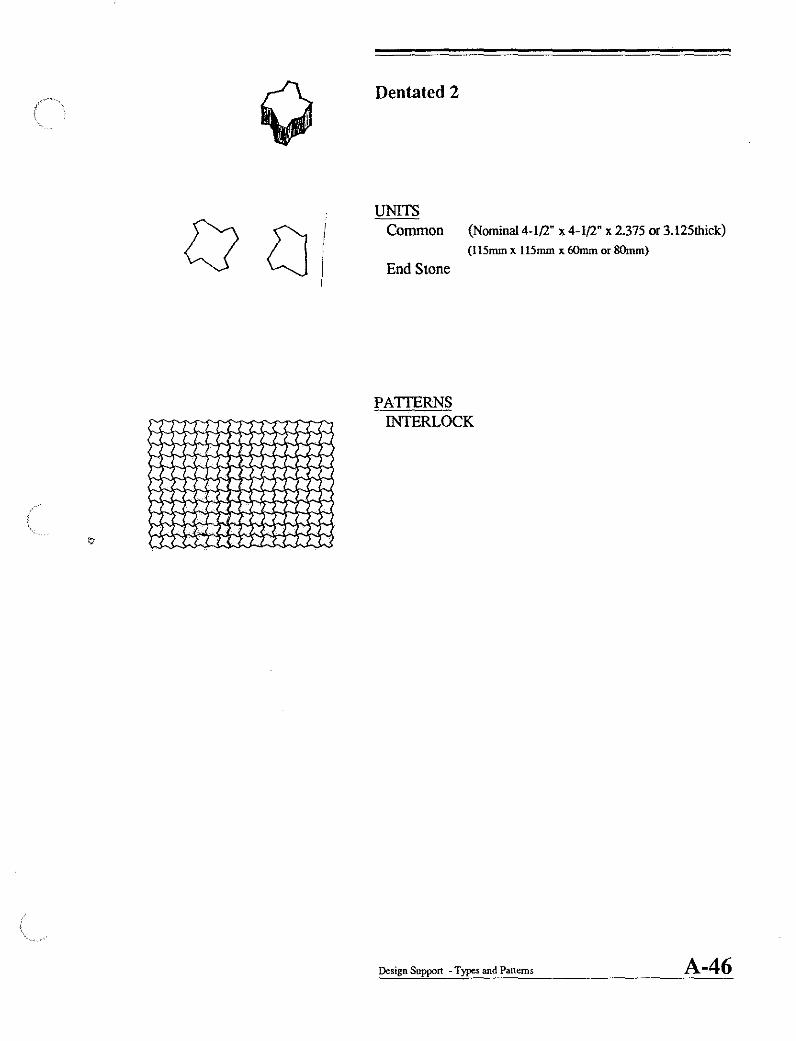
Dentated 2
UNITS Common (Nominal4-1{2" x4-1{2" x 2375 or3.125thick)
(115mm x 115mm x 60rnm or SOmm)
End Stone
PATIERNS INTERLOCK
Design Support - Types and Patterns A-46
I r J: !
-/-1 ,
!
I J , 1l::J
I, 11 ~
::J 1:- A -~ :J
I ; I
; , , ):: -'1-1
~ : lJ ,n
'II ..Jl
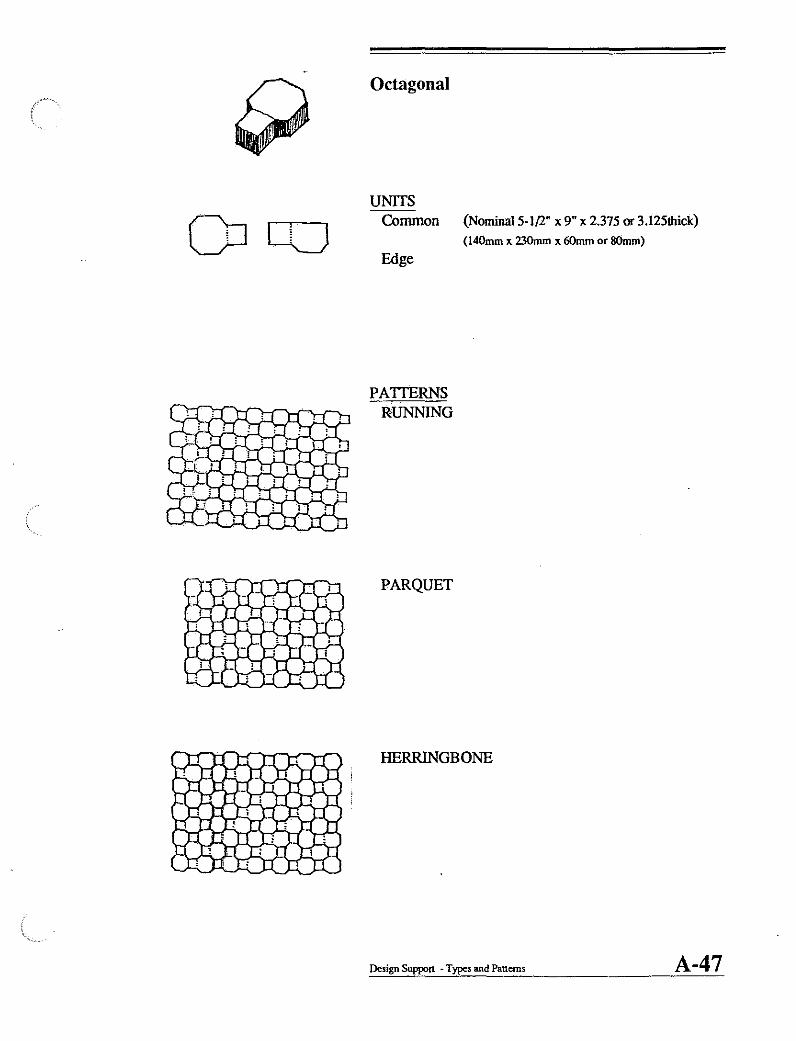
Octagonal
UNITS Common (Nominal 5-1/2" x 9" x 2.375 or 3.l25thick)
Edge
PATIERNS RUNNING
PARQUET
(l40mm x 230mm x 60mm or 8Omm)
HERRINGBONE
Design Support - Types and Patterns A-47

Octagonal 2
UNITS Common (Nominal4-1{2" x 9" x 2.375 or 3.125thick)
(115mm x 230mm x 60mm or 8Omm)
PATTERNS INTERLOCK
Design Support ~ Types and Patterns A-48

o
Lock
UNITS Common (NominaI4.1(l" x 9" x 2.375 or 3.125thick)
(115mm x 230mm x 60mm or 8Omm)
Edge block End block
IPATrERNS ! RUNNING
Design Support - Types and Patterns A-49

Tri-Hexagon
UNITS Common (Nominal 9" x 9" x 2.375thick)
Edge stone S tarter stone
PATIERNS RUNNING
STACK
WEAVE
(230mm x 230mm x SOmm)
Design Support - Types and Patterns A-50

I-Block
UNITS Common (Nominal4-1{l." x 9" x 2.375 or 3.125thick)
(l15mm x 230mm x 60mm or 8Omm)
HaIfunits
PATTERNS Rum.'ING
Design Support - Types and Patterns A·51
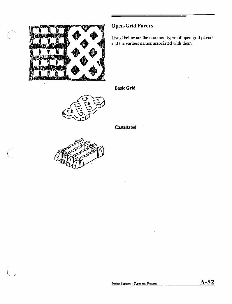
Open-Grid Pavers
Listed below are the common types of open grid pavers and the various names associated with them.
Basic Grid
Castellated
Design Support - Types and Patterns A-52
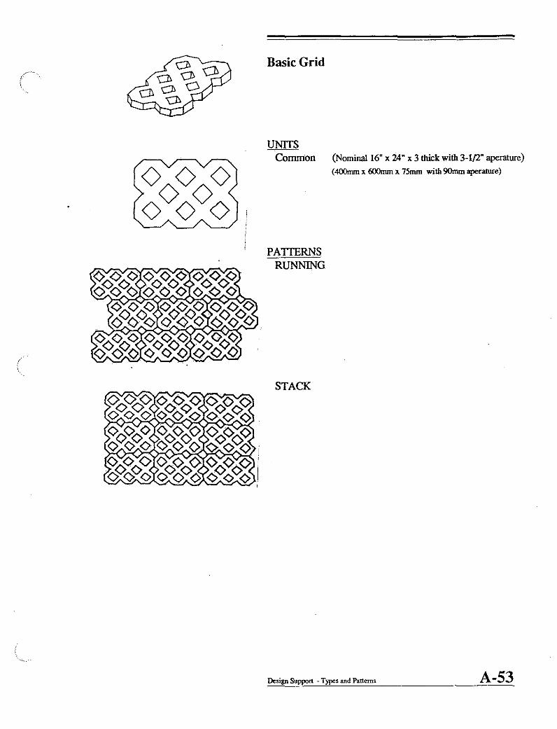
Basic Grid
UNITS Common (Nominal 16" x 24" x 3 thick with 3-1/2" aperature)
(4OOmm x 600mm x 75mm with 90mm aperature)
PATfERNS RUNNING
STACK
Design Support - Types and Patterns A-53

Castellated
UNITS Common (Nominal 16" x 24" x 4-3/4" thick)
(4OOmm x 600mm xl20mm)
PATIERNS RUNNING
Design Support. Types and Patterns A-54

PRESENTATION
This division of the manual provides support materials for the preparation of presentations relative to the use of concrete pavers. It is the intent of this division to simplify the process of locating and organizing the support materials for preparing lectures, presentations and seminars by cross referencing the information to the outline developed in the fust division of DESIGN
SUPPORT. The two types of presentation support included in this division are;
SLIDES Slides within this division are fust referenced to the general outline from Page A-2 in Design Support. This allows the user to search for actual illustrations of the specific principles. Secondly, the slides are referenced by the type of project they represent (ie plazas, walks, roads, parking lots, etc.) Finally, the slides are fIled and grouped according to their locations alphabetically.
OVERHEAD TRANSPARANCIES Overhead ttansparancies are organized according to the general outline from Page A-2 in Design Support. The principles and illustrations have been captured .as individual, labeled transparancies for use in classroom or presentation environments.
B-1

SLIDES BY OUTLINE
. GENERAL INFORMATION Generic types Slide B-
Solid Interlocking Slide B-Open Grid Slide B-
Applications Slide B-Solid Interlocking Pedestrian Slide B-Solid Interlocking Vehicular Slide B-Solid Interlocking Industrial Slide B-Open Grid Vehicular Slide B-Open Grid Landscape Slide B-
Advantages Slide B-Design Variety Slide B-Environmental Impact Slide B-Safety Slide B-Zip and Unzip Slide B-Cost Slide B-
DESIGN PRINCIPLES Slide B-Urban Carpet Slide B-
Mosaics Slide B-Scale Slide B-Zoning Slide B-Markers Slide B-Emphasis Slide B-Edges Slide B-
Green Structure Slide B-Green/Gray Balance Slide B-DistrIbution Slide B-
TECHNICAL PRINCIPLES Slide B-Structural Principles Slide B-
Continuous/Contiguous Slide B-Edge Restraint Slide B-Five Layers Slide B-
Construction Principles Slide B-Edge Integration Slide B-Installation methods Slide B-
TYPES AND PATTERNS Slide B-Interlocking Slide B-
Rectangular Slide B-Dentated Slide B-Dentated 2 Slide B-Octagonal Slide B-Octagonal 2 Slide B-Lock Slide B-Tri-hexagonal Slide B-I-Block Slide B-
Open Grid Slide B-Basic grid Slide B-Castellated Slide B-
Presentation support -Slides B-2

(
SOLID INTERLOCKING LINEAR APPLICATIONS
Walks Paths Building borders Shoulders
PLANAR APPLICATIONS Plazas Patios Ground cover
OPEN GRID LINEAR APPLICATIONS
Drives Shoulders
PLANAR APPLICATIONS Parlcing Soil stabilization
SLIDES BY APPLICATION
Slide Slide Slide
BBB-
B-
Presentation Support - Slides
B- B- B-
B-3

BUFFALO Parking lot Downtown Plaza
DAYTON Downtown Pedestria1 Mall Etc.
SLIDES AS FILED IN ORDER
Slide Slide
Slide
B-1 B-3
B-2 B-4
B-6 B-8
Presentation support - Slides
B-5 B-6
B-9
B-4

GENERAL INFORMATION Generic types
Solid Interlocking Open Grid
Applications Solid Interlocking Pedestrian Solid Interlocking Vehicular Solid Interlocking Industrial Open Grid Vehicular Open Grid Landscape
Advantages Design Variety Environmental Impact Safety Zip and Unzip Cost
DESIGN PRINCIPLES Urban Carpet
Mosaics Scale Zoning Mad:ers Emphasis Edges
Green Structure Green/Gray Balance Distribution
TECHNICAL PRINCIPLES Structural Principles
Continuous/Contiguous Edge Restraint Five Layers
Construction Principles Edge Integration Installation methods
TYPES AND PATTERNS Interlocking
Rectangular Dentated Dentated 2 Octagonal Octagonal 2 Lock Tri·hexagonal I·Block
Open Grid Basic grid Castellated
TRANSPARANCIES BY OUTLINE
Page B·TI
Page B·T2 Page B·T3 Page B·T4 Page B·T5 Page B·T6 Page B·T7
Page B·T8 Page B·T9 Page B·TIO Page B·Tll Page B·Tl2
Page B·Tl3 Page B·Tl4 Page B·TlS Page B·Tl6 Page B·Tl7 Page B·Tl8 Page B·T!9 Page B·T20 Page B·T2! Page B·T22
Page B·T23 Page B·T24 Page B·lli Page B·T26 Page B·T27 Page B·T28 Page B·T29
Page B·T30 Page B·T3! Page B·T32 Page B·T33 Page B·T34 Page B·T35 Page B·T36 Page B·T37 Page B·T38 Page B:T39 Page B·T40 Page B·T4!
Presentation Support -Trnnsparancies B-5