970-1024 DESCRIPTION: MODULAR INCREMENTAL …... date 09/05/2017 page 1 of 8 970-1024 DESCRIPTION:...
8
www.applied-motion.com date 09/05/2017 page 1 of 8 970-1024 │ DESCRIPTION: MODULAR INCREMENTAL ENCODER ELECTRICAL parameter conditions/description min typ max units power supply VDD 4.5 5 5.5 V start up time 200 ms current consumption with unloaded output 16 mA differential RS-422 channels output high level output low level output current (per channel) rise/fall time 3 7 11 0.1 25 20 V V mA ns INCREMENTAL CHARACTERISTICS parameter conditions/description min typ max units channels Quadrature Line Driver A, A, B, B, Z, Z waveform CMOS voltage square wave phase difference A leads B for CCW rotation (viewed from front) quadrature resolutions 1 48, 96, 100, 125, 192, 200, 250, 256, 384, 400, 500, 512, 768, 800, 1000, 1024, 1600, 2000, 2048, 4096 PPR index 2 one pulse per 360 degree rotation accuracy 0.2 degrees quadrature duty cycle 50 % Notes: 1. Resolution programmed with AMT Viewpoint™ PC software. Default resolution set to 2048 PPR. 2. Zero position alignment set with AMT One Touch Zero™ module, AMT Viewpoint™ PC software, or serial commands FEATURES • patented capacitive ASIC technology • low power consumption • incremental resolutions up to 4096 PPR • resolutions programmable with AMT Viewpoint™ PC software • differential line driver • digitally set zero position • compact modular package with locking hub for ease of installation • radial cable connection • 7 different mounting hole options • -40~105°C operating temperature ¯ ¯ ¯
Transcript of 970-1024 DESCRIPTION: MODULAR INCREMENTAL …... date 09/05/2017 page 1 of 8 970-1024 DESCRIPTION:...

www.applied-motion.com
date 09/05/2017
page 1 of 8
970-1024 │ DESCRIPTION: MODULAR INCREMENTAL ENCODER
ELECTRICALparameter conditions/description min typ max units
power supply VDD 4.5 5 5.5 V
start up time 200 ms
current consumption with unloaded output 16 mA
differential RS-422 channels
output high leveloutput low leveloutput current (per channel)rise/fall time
3
7 11
0.12520
VV
mAns
INCREMENTAL CHARACTERISTICSparameter conditions/description min typ max units
channels Quadrature Line Driver A, A, B, B, Z, Z
waveform CMOS voltage square wave
phase difference A leads B for CCW rotation (viewed from front)
quadrature resolutions1 48, 96, 100, 125, 192, 200, 250, 256, 384, 400, 500, 512, 768, 800, 1000, 1024, 1600, 2000, 2048, 4096 PPR
index2 one pulse per 360 degree rotation
accuracy 0.2 degrees
quadrature duty cycle 50 %Notes: 1. Resolution programmed with AMT Viewpoint™ PC software. Default resolution set to 2048 PPR. 2. Zero position alignment set with AMT One Touch Zero™ module, AMT Viewpoint™ PC software, or serial commands
FEATURES• patented capacitive ASIC technology• low power consumption• incremental resolutions up to 4096 PPR• resolutions programmable with AMT Viewpoint™ PC software• differential line driver• digitally set zero position• compact modular package with locking hub for ease of installation• radial cable connection• 7 different mounting hole options• -40~105°C operating temperature
¯ ¯ ¯
www.applied-motion.com
date 09/05/2017 │ page 2 of 8 970-1024 │ DESCRIPTION: MODULAR INCREMENTAL ENCODER
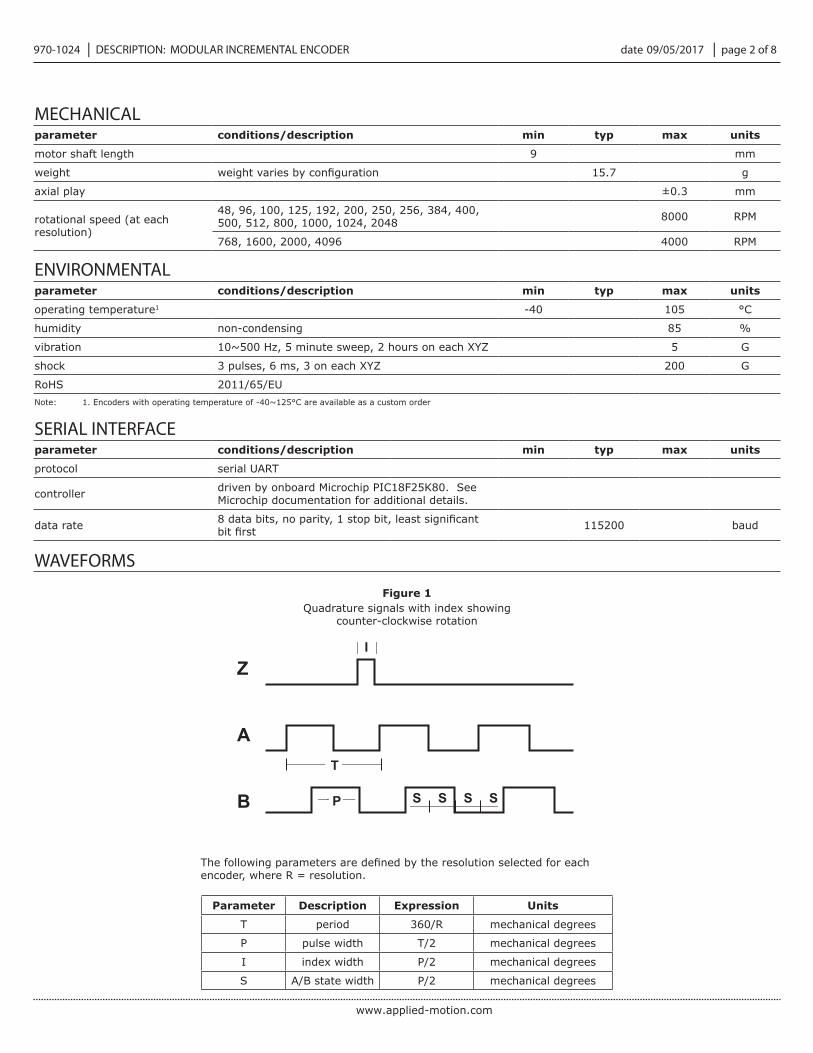
WAVEFORMS
Z
A
B
I
P
T
S S S S
Quadrature signals with index showing counter-clockwise rotation
Figure 1
MECHANICALparameter conditions/description min typ max units
motor shaft length 9 mm
weight 15.7 g
axial play ±0.3 mm
rotational speed (at each resolution)
48, 96, 100, 125, 192, 200, 250, 256, 384, 400, 500, 512, 800, 1000, 1024, 2048 8000 RPM
768, 1600, 2000, 4096 4000 RPM
ENVIRONMENTALparameter conditions/description min typ max units
operating temperature1 -40 105 °C
humidity non-condensing 85 %
vibration 10~500 Hz, 5 minute sweep, 2 hours on each XYZ 5 G
shock 3 pulses, 6 ms, 3 on each XYZ 200 G
RoHS 2011/65/EUNote: 1. Encoders with operating temperature of -40~125°C are available as a custom order
SERIAL INTERFACEparameter conditions/description min typ max units
protocol serial UART
controller driven by onboard Microchip PIC18F25K80. See Microchip documentation for additional details.
data rate 115200 baud
Parameter Description Expression Units
T period 360/R mechanical degrees
P pulse width T/2 mechanical degrees
I index width P/2 mechanical degrees
S A/B state width P/2 mechanical degrees
encoder, where R = resolution.
www.applied-motion.com
date 09/05/2017 │ page 3 of 8 970-1024 │ DESCRIPTION: MODULAR INCREMENTAL ENCODER
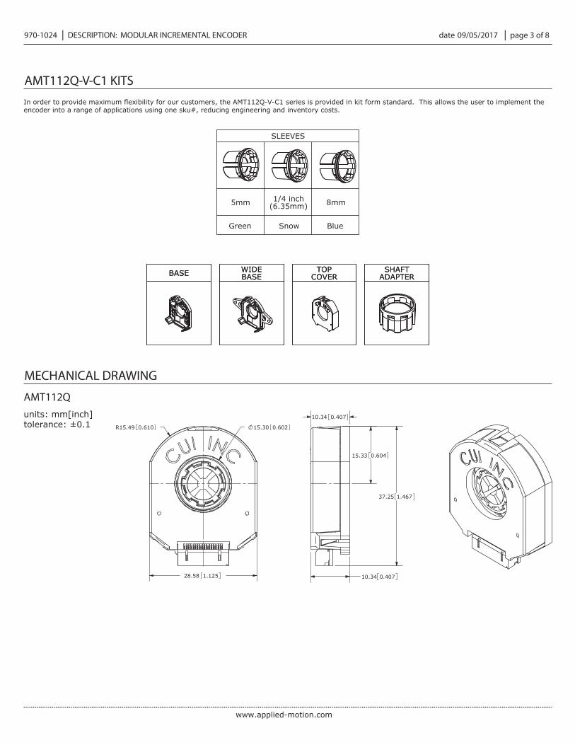
AMT112Q-V-C1 KITS
encoder into a range of applications using one sku#, reducing engineering and inventory costs.
SLEEVES
5mm 1/4 inch (6.35mm) 8mm
BASE WIDEBASE
TOPCOVER
SHAFTADAPTERBASE WIDE
BASETOP
COVERSHAFT
ADAPTER
Green Snow Blue
MECHANICAL DRAWING
units: mm[inch]tolerance: ±0.1
AMT112Q
15.33 0.604
0.60215.30R15.49 0.610
28.58 1.125
0.40710.34
37.25 1.467
10.34 0.407

www.applied-motion.com
date 09/05/2017 │ page 4 of 8 970-1024 │ DESCRIPTION: MODULAR INCREMENTAL ENCODER
MECHANICAL DRAWING (CONTINUED)
units: mm[inch]tolerance: ±0.1
MOUNTING HOLE PATTERNS
25.40 1.000
16.00 0.630
20.90 0.823
21.55 0.848
22.00 0.866
19.05 0.750
0.275 0.011
(3 PLCS)A
0.116
0.067(2 PLCS)
2.95
(4 PLCS)0.0792.00
(2 PLCS)
1.70
12.60[0.496]
DETAIL ASCALE 4 : 1
R1.05 0.041
STANDARD BASE
units: mm[inch]tolerance: ±0.1
46.20 1.819
32.44 1.277
2.87 0.113(2 PLCS)
3.00 0.118(2 PLCS)
WIDE BASE

www.applied-motion.com
date 09/05/2017 │ page 5 of 8 970-1024 │ DESCRIPTION: MODULAR INCREMENTAL ENCODER
15
14
13
16
SCALE 4 : 1
1
2
3
4
5
6
7
8
9
10
11
12
SECTION A-A
17
AA
ENCODER INTERFACE
PINOUT CONNECTOR
Function
# Signal Name
1 TX_ENC+
2 RX_ENC+
3 N/A
4 GND1
5 N/A
6 +5 V
7 N/A
8 B+
9 B-
10 A+
11 A-
12 Z+
13 Z-
14 MCLRB
15 N/A
16 N/A
17 N/A
AMT112Q
Mating Connector: JAE FI-W17S
Note: 1. Connect encoder GND to motor chassis as closely as possible. For additional grounding techniques contact CUI Application Support.
www.applied-motion.com
date 09/05/2017 │ page 6 of 8 970-1024 │ DESCRIPTION: MODULAR INCREMENTAL ENCODER
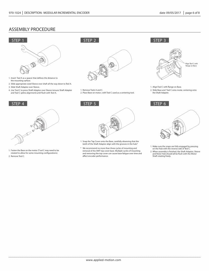
1. Insert Tool A as a spacer that defines the distance to the mounting surface.
2. Slide appropriate sized Sleeve over shaft all the way down to Tool A.3. Slide Shaft Adaptor over Sleeve.4. Use Tool C to press Shaft Adaptor over Sleeve (ensure Shaft Adapter
and Tool C spline alignment) until flush with Tool A.1. Remove Tools A and C. 2. Place Base on moto r, with Tool C used as a centering tool.
1. Fasten the Base on the motor (Tool C may need to be rotated to allow for some mounting configurations).
2. Remove Tool C.
1. Make sure the snaps are fully engaged by pressing on the Hub with the reverse side of Tool C.
2. When assembly is finished, the Shaft Adaptor, Sleeve and Rotor Hub should all be flush with the Motor Shaft rotating freely.
1. Snap the Top Cover onto the Base, carefully observing that the teeth of the Shaft Adaptor align with the grooves in the hub. *
* We recommend no more than three cycles of mounting and removal of the AMT top cover base. Multiple cycles of mounting and removing the top cover can cause base fatigue over time and a�ect encoder performance.
1. Align Tool C with flange on Base.2. Slide Base and Tool C onto motor, centering onto
the Shaft Adapter.
STEP 1
STEP 4
STEP 2
STEP 5
STEP 3
STEP 6
Align Tool C with flange on Base
ASSEMBLY PROCEDURE
www.applied-motion.com
date 09/05/2017 │ page 7 of 8 970-1024│ DESCRIPTION: MODULAR INCREMENTAL ENCODER
Command Action Use
0 This command sends an ascii ‘0’ (hex value 0x30).
This zeros the encoder and sets the index at the current angular position. This position is stored in non-volatile memory and will remain present until a zero command is set again or encoder is reprogrammed via AMT Viewpoint™.
Q This command sends an ascii ‘Q’ (hex value 0x51). This command restarts the encoder as if it were power cycled.
APPLICATION NOTES
Pin Description Connection
TX_ENC+ This is the pin that the encoder transmits serial data on. Connect this pin to the receiver input of your serial/UART interface.
RX_ENC+ This is the pin that the encoder receives serial commands on. Connect this pin to your serial/UART interface transmitter output.
MCLRBThis pin is used to force the encoder into reset for reprogramming via the AMT Viewpoint™ application.
Connection of this pin is not required for the above serial commands.
4 5
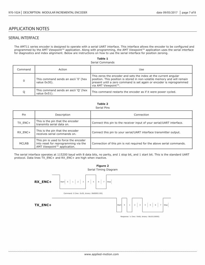
Command: 0 (hex: 0x30, binary: 0b00001100)
Start 0 1 2 3
Response: \r (hex: 0x0d, binary: 0b10110000)
Stop
Stop7TX_ENC+ Start 0 1 2 3 4 5 6
RX_ENC+ 6 7
programmed by the AMT Viewpoint™ application. Along with programming, the AMT Viewpoint™ application uses the serial interface for diagnostics and index alignment. Below are instructions on how to use the serial interface for position zeroing.
Serial CommandsTable 1
Serial PinsTable 2
Serial Timing DiagramFigure 2
The serial interface operates at 115200 baud with 8 data bits, no parity, and 1 stop bit, and 1 start bit. This is the standard UART protocol. Data lines TX_ENC+ and RX_ENC+ are high when inactive.
SERIAL INTERFACE

date 09/05/2017 │ page 8 of 8 970-1024
Document No. 970-1024 revision B
│ DESCRIPTION: MODULAR INCREMENTAL ENCODER
Headquarters404 Westridge DriveWatsonville, CA 95076800.525.1609www.applied-motion.com
rev. description date
1.0 initial release 01/25/20171.01 removed tool A and tool C 09/05/2017
The revision history provided is for informational purposes only and is believed to be accurate.
REVISION HISTORY