9/6/2011 A 4-bit adder - · PDF fileA 4-bit adder • Four full adders together ... –...
17
9/6/2011 1 A 4-bit adder • Four full adders together make a 4-bit adder. • There are nine total inputs: – Two 4-bit numbers, A3 A2 A1 A0 and B3 B2 B1 B0 – An initial carry in, CI • The five outputs are: – A 4-bit sum, S3 S2 S1 S0 – A carry out, CO • Imagine designing a nine-input adder without this hierarchical structure—you’d have a 512-row truth table with five outputs! Hierarchical adder design • When you add two 4-bit numbers the carry in is always 0, so why does the 4-bit adder have a CI input? • One reason is so we can put 4-bit adders together to make even larger adders! This is just like how we put four full adders together to make the 4- bit adder in the first place. • Here is an 8-bit adder, for example. • CI is also useful for subtraction, as we’ll see next week.
Transcript of 9/6/2011 A 4-bit adder - · PDF fileA 4-bit adder • Four full adders together ... –...

9/6/2011
1
A 4-bit adder
• Four full adders together make a 4-bit adder.
• There are nine total inputs:
– Two 4-bit numbers, A3 A2 A1 A0 and B3 B2 B1 B0
– An initial carry in, CI
• The five outputs are:
– A 4-bit sum, S3 S2 S1 S0
– A carry out, CO
• Imagine designing a nine-input adder without this
hierarchical structure—you’d have a 512-row truth table
with five outputs!
Hierarchical adder design
• When you add two 4-bit numbers the carry in is always 0, so why does the 4-bit adder have a CI input?
• One reason is so we can put 4-bit adders together to make even larger adders! This is just like how we put four full adders together to make the 4-bit adder in the first place.
• Here is an 8-bit adder, for example.
• CI is also useful for subtraction, as we’ll see next week.
9/6/2011
2
16 bit full adder
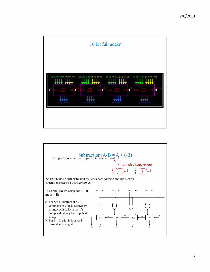
Subtraction: A-B = A + (-B)Using 2’s complement representation: –B = ~B + 1
~ = bit-wise complement
B0
B B1
B
So let’s build an arithmetic unit that does both addition and subtraction.
Operation selected by control input:
FA FA FA FA
S
B3
C3
S2 S1 S0S3C4
C2 C1 C0
A 3 B2 A 2 B1 A 1 B0 A 0The circuit shown computes A + B
and A – B:
� For S = 1, subtract, the 2’s
complement of B is formed by
using XORs to form the 1’s
comp and adding the 1 applied
to C0.
� For S = 0, add, B is passed
through unchanged

9/6/2011
3
4-bit ripple-carry adder/subtractor
A-B =A+(-B) =A+2’s compliment of B =A+ 1’s compliment of B + 1
Algebraic carry out hocus-pocus
• Let’s look at the carry out equations for specific bits, using the general equation from the previous page ci+1 = gi + pici:
• These expressions are all sums of products, so we can use them to make a circuit with only a two-level delay.
c1 = g0 + p0c0
c2 = g1 + p1c1= g1 + p1(g0 + p0c0)
= g1 + p1g0 + p1p0c0
c3 = g2 + p2c2= g2 + p2(g1 + p1g0 + p1p0c0)
= g2 + p2g1 + p2p1g0 + p2p1p0c0
c4 = g3 + p3c3= g3 + p3(g2 + p2g1 + p2p1g0 + p2p1p0c0)
= g3 + p3g2 + p3p2g1 + p3p2p1g0 + p3p2p1p0c0
9/6/2011
4
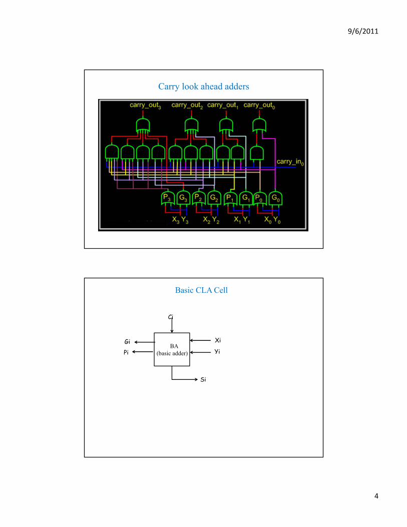
Carry look ahead adders
Basic CLA Cell
BA
(basic adder)
Xi
Yi
Ci
Gi
Pi
Si

9/6/2011
5
Carry Look-Ahead Adder Design
4-bit Carry-Look Ahead Adder
Ci+1 = Gi + Pi.Ci
Gi = Ai.Bi
Pi= (Ai ⊕ Bi)
Carry-lookahead adder (CLA)

9/6/2011
6
4 bit CLA
4 bit
CLA
44
XY
Cin
S
GP
Cout
Hierarchical approach to wider adders
4 bit
CLA
44
4 bit
CLA
44
4 bit
CLA
44
4 bit
CLA
44
g3 p3 g1 p1g2 p2
S3-S0S7-S4
g0 p0
S15-S12 S11-S8
X3-X0X7-X4X15-X12 X11-X8 Y3-Y0Y7-Y4Y15-Y12 Y11-Y8
C0C4C8C12
C16
9/6/2011
7
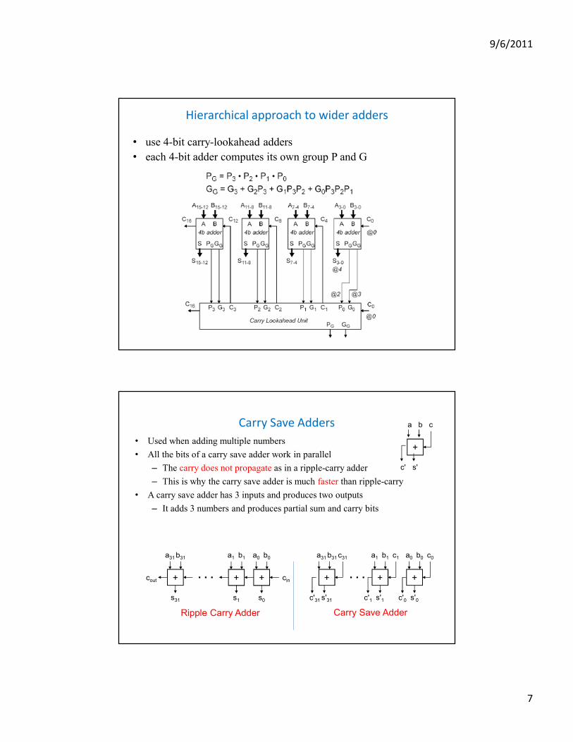
Hierarchical approach to wider adders
• use 4-bit carry-lookahead adders
• each 4-bit adder computes its own group P and G
Carry Save Adders
• Used when adding multiple numbers
• All the bits of a carry save adder work in parallel
– The carry does not propagate as in a ripple-carry adder
– This is why the carry save adder is much faster than ripple-carry
• A carry save adder has 3 inputs and produces two outputs
– It adds 3 numbers and produces partial sum and carry bits
Ripple Carry Adder
+
a0 b0
s0
+
a1 b1
s1
+
a31 b31
s31
. . .cout cin
Carry Save Adder
. . .+
a31 b31
s'31c'31
c31
+
a1 b1
s'1c'1
c1
+
a0 b0
s'0c'0
c0
+
a b
s'c'
c

9/6/2011
8
Consider Adding: S = A + B + C + D
++++
++++
+++
d0d1d2d3
a0a1a2a3 b0b1b2b3
+
s0s1s2s3s4s5
c0c1c2c3
Ripple Carry Adder
Ripple Carry Adder
Ripple Carry Adder
A B
C
S
D
Carry Save Adder
Ripple Carry Adder
A B C
D
S
Carry Save Adder
++++
++++
++++
d0d1d2d3
c0c1c2c3
a0a1a2a3 b0b1b2b3
+
s0s1s2s3s4s5
Example:
X=12345
Y=38172
+ Z=20587

9/6/2011
9
Carry Save Addition (Decimal)
Carry Save Addition (Binary)
Let X: 1 0 0 1 1, Y: 1 1 0 0 1 and Z: 0 1 0 1 1
9/6/2011
10
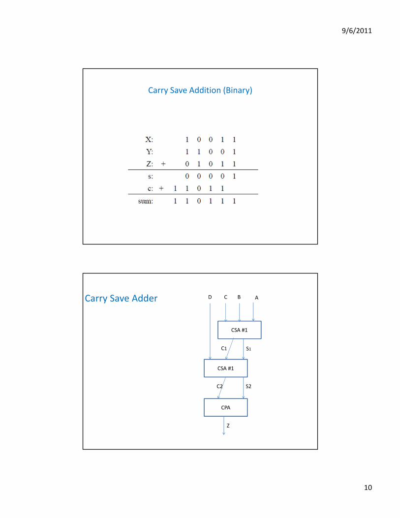
Carry Save Addition (Binary)
Carry Save Adder
CSA #1
CSA #1
CPA
S1C1
ABCD
S2C2
Z
9/6/2011
11
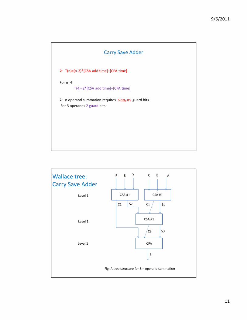
Carry Save Adder
� T(n)=(n-2)*[CSA add time]+[CPA time]
For n=4
T(4)=2*[CSA add time]+[CPA time]
� n operand summation requiresɾ�����ɿguard bits
For 3 operands 2 guard bits.
CSA #1
CSA #1
CPA
S1C1
ABCD
S2C2
Z
CSA #1
F E
C3 S3
Level 1
Level 1
Level 1
Wallace tree:
Carry Save Adder
Fig: A tree structure for 6 – operand summation
9/6/2011
12
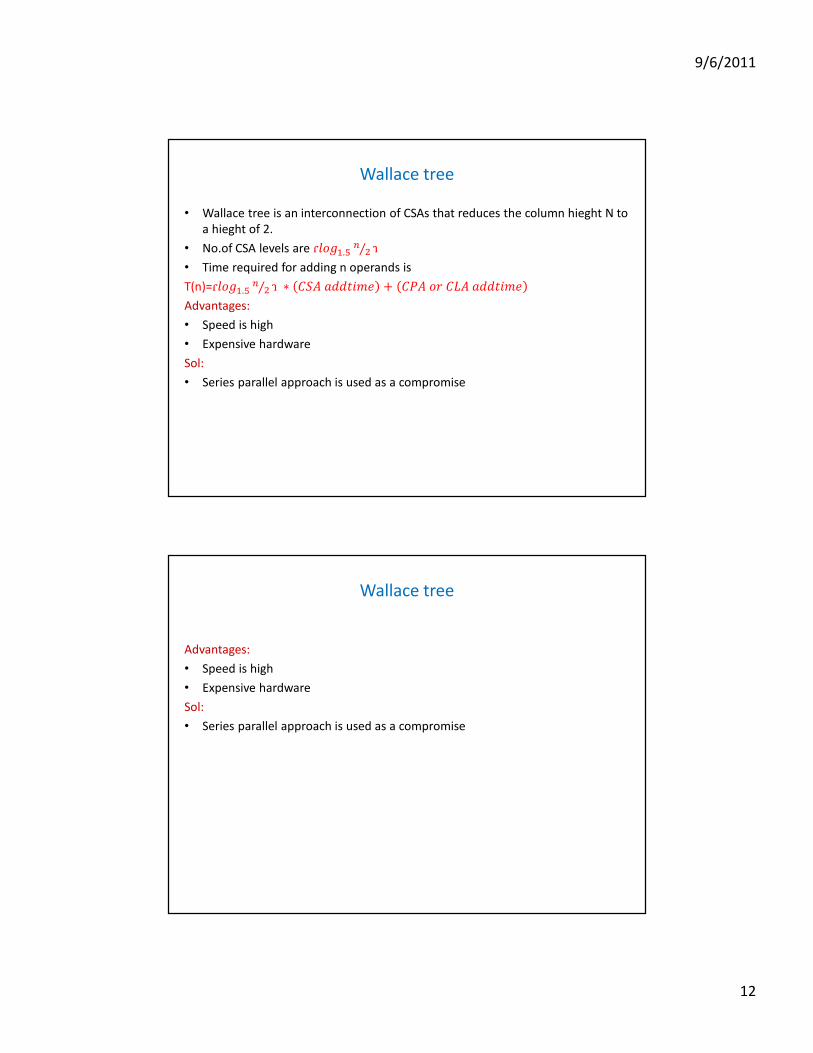
Wallace tree
• Wallace tree is an interconnection of CSAs that reduces the column hieght N to
a hieght of 2.
• No.of CSA levels are ɾ���.���⁄ ɿ
• Time required for adding n operands is
T(n)=ɾ���.���⁄ ɿ ∗ ���������� + ���������������
Advantages:
• Speed is high
• Expensive hardware
Sol:
• Series parallel approach is used as a compromise
Wallace tree
Advantages:
• Speed is high
• Expensive hardware
Sol:
• Series parallel approach is used as a compromise

9/6/2011
13
Series parallel approach
• If n=2k for k>1 no.of adders required is (n-1)
• If ‘m’ is no.of bits per operand then
T(n)=m*(clock period)*(�����)*(fulladder time)
1 0 0
0 1 1
1 0 1
1 1 0
FA
FA
delay
delay
FA
delay
0
0

9/6/2011
14
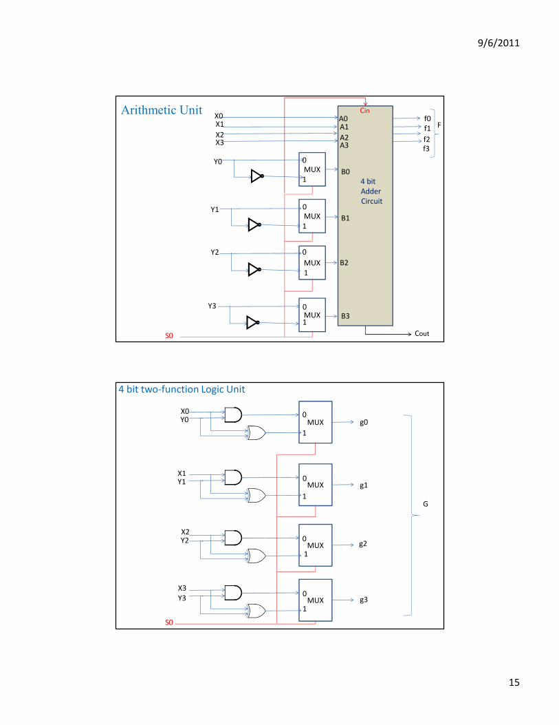
ALU Design
ALU has 2 segments: Arithmetic Unit
Logic Unit
Arithmetic Unit
• Two function arithmetic
• If So = 0 then F= X+Y
else F=X+��+1
=X-Y
9/6/2011
15
MUX
MUX
MUX
MUX
0
1
X2
Y2
f1
0
1
X3
Y3
f0
0
1
X0
Y0
f2
0
1
X1
Y1
f3
S0
4 bit
Adder
Circuit
A2A3
A0A1
B2
B3
B0
B1
Cout
CinArithmetic UnitF
MUX
MUX
MUX
MUX
0
1
X2Y2
g1
0
1
X3
Y3
g0
0
1
X0Y0
g2
0
1
X1Y1
g3
S0
4 bit two-function Logic Unit
G
9/6/2011
16
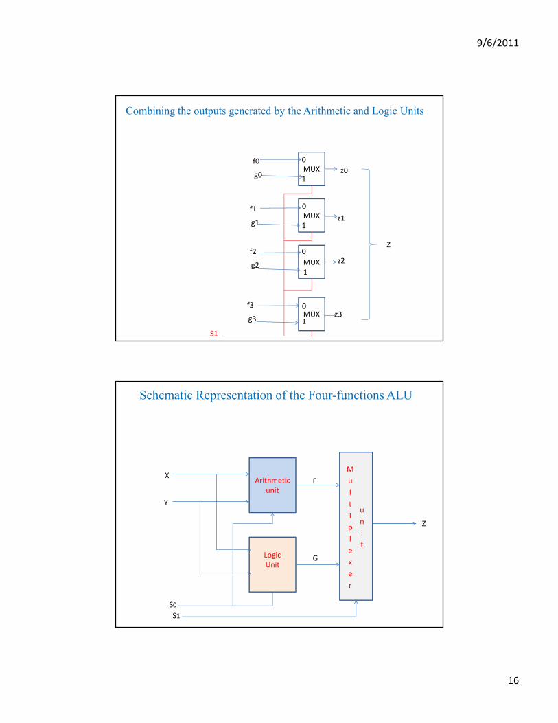
Combining the outputs generated by the Arithmetic and Logic Units
MUX
MUX
MUX
MUX
0
1
f2
0
1
f3
0
1
f0
0
1
f1
g2
g3
g0
g1
z2
z3
z0
z1
Z
S1
Schematic Representation of the Four-functions ALU
M
u
l
t
i
p
l
e
x
e
r
u
n
i
t
Arithmetic
unit
Logic
Unit
X
Y
Z
S0
S1
F
G
9/6/2011
17
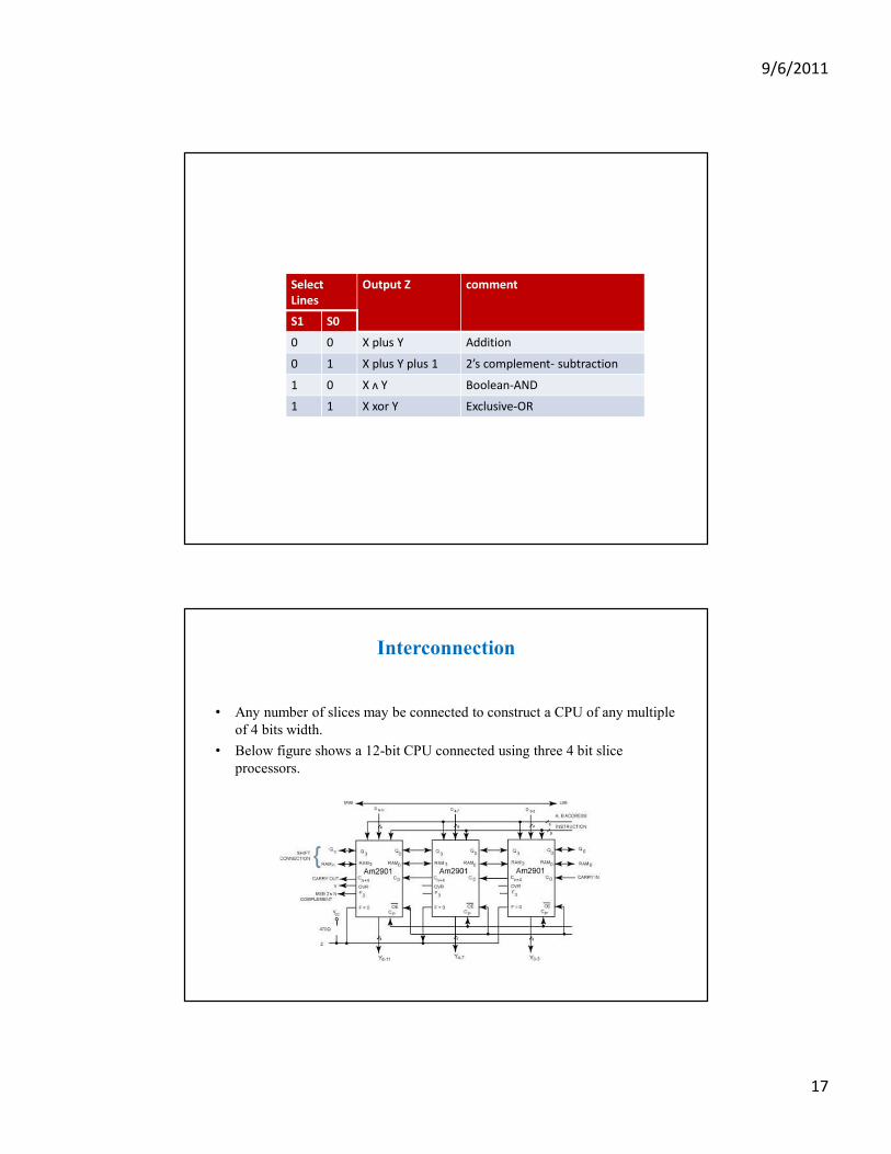
Select
Lines
Output Z comment
S1 S0
0 0 X plus Y Addition
0 1 X plus Y plus 1 2’s complement- subtraction
1 0 X ʌ Y Boolean-AND
1 1 X xor Y Exclusive-OR
Interconnection
• Any number of slices may be connected to construct a CPU of any multiple
of 4 bits width.
• Below figure shows a 12-bit CPU connected using three 4 bit slice
processors.