91 Burrendong Road +61 7 5529 6892 … · Figure 1 - diagrid roof for bowling green Keywords:...
9
CarbonWorks – The Design and Build Specialist 1 91 Burrendong Road Coombabah 4216 Queensland, Australia +61 7 5529 6892 www.carbon-works.com.au From CarbonWorks… Doc No 181-10 Release 1 CarbonWorks - Roof Shell Investigation 31-10-2014 Author: Peter Schwarzel Figure 1 - diagrid roof for bowling green Keywords: Tessellation, mapping, panelisation, waffle structure, Voronoi, diagrid, isogrid, gridshell, geodesic domes, hexgrid Background I've been interested in geodesic domes since I left school. I built small cardboard domes, wireframes and various polyhedra solids. I also tried to use my engineering studies to analyse these things but unfortunately my maths was not up to it. This put me on a path to use computers to design these interesting structures. Geodesics have had trouble becoming popular due to their manufacturing difficulties. Each element length is different & each angle is different making manufacture complex. This investigation looks at various grid structures that maybe useful to create large, near spherical roof structures. With the now common usage of parametric CAD and nurbs modellers and FE programs it is now possible to design and analyse a grid shell structure like a bowling green shade roof in a very short period of time.
Transcript of 91 Burrendong Road +61 7 5529 6892 … · Figure 1 - diagrid roof for bowling green Keywords:...
CarbonWorks – The Design and Build Specialist 1
91 Burrendong Road
Coombabah 4216 Queensland, Australia
+61 7 5529 6892 www.carbon-works.com.au
From CarbonWorks… Doc No 181-10 Release 1 CarbonWorks - Roof Shell Investigation 31-10-2014 Author: Peter Schwarzel
Figure 1 - diagrid roof for bowling green
Keywords: Tessellation, mapping, panelisation, waffle structure, Voronoi, diagrid, isogrid, gridshell, geodesic domes, hexgrid Background I've been interested in geodesic domes since I left school. I built small cardboard domes, wireframes and various polyhedra solids. I also tried to use my engineering studies to analyse these things but unfortunately my maths was not up to it. This put me on a path to use computers to design these interesting structures. Geodesics have had trouble becoming popular due to their manufacturing difficulties. Each element length is different & each angle is different making manufacture complex. This investigation looks at various grid structures that maybe useful to create large, near spherical roof structures. With the now common usage of parametric CAD and nurbs modellers and FE programs it is now possible to design and analyse a grid shell structure like a bowling green shade roof in a very short period of time.

CarbonWorks – The Design and Build Specialist 2
Intent 1) To investigate and rationalise a suitable construction method for membrane roof structures. The investigation aims at determining a suitable structural configuration, choosing between geodesic, quadgrid, hexgrid, diagrid, and great circle types. Although all the configurations are possible to build, the simplest and most economic needs to be determined. Tradition planar or single curvature ortho grid construction does not take advantage of membrane effects and depends primarily on bending stiffness to resist structural actions. Thin double curvature shells offer the possibility of being very light weight and strong structures due to their self stiffening characteristics. 2) To showcase some of CarbonWorks capabilities and interests in the search for project work. General Process: Using a potential 40mx40m bowling green shade structure as an example we work through various shell structures and determine a possibly economic approach to producing such a roof. The general work flow is: 1) Using a NURBS modeller, draw up a flat pattern of the test grid (or grillage) 40mx40m 2) Loft a suitable design surface over a 40m x40m patch. Pure spheres & near spherical roofs are considered but other freeform shapes are just as easy to create. This is done in Rhino3D software. This is called the shell surface 3) The flat grillage is then transposed onto the shell surface. Now we have a 3D freeform grillage that is the correct near shape for our purpose 4) We pick a near sherical surface as this is a very efficient shape to resist wind pressure loads and local contact loads. Traditional single curvature shapes require several trusses or heavy beams in the none curved direction to resist the applied loads. A spherical surface offers the opportunity to produce the thinnest, lightest structural solution. The lightest solution uses the least materials so should provide a low cost solution 5) By exporting the grillage via a dfx file we straighten out the slightly curved beams. We require straight beams as these are the cheapest beam solution 6) This dxf grillage is then imported into an FE program, in my case Strand7. The model is given properties, we apply loads and run the model. All this takes less then 30mins for a candidate concept 7) Camber - There is a minimium camber required for a shell. In a separate exercise I built beams and domes of graded camber. It turns out that under ~10% camber the shell can be unstable ie it can "snap through" or oil can very easily. So all the shells in this investigation shall have 10% camber. 8) Loadcase - I've used AS1170.2 to determine a suitable ultimate pressure distribution at 50m/s wind speed. Using a 80% shade cloth and using the porosity allowances and curved roof tables results in a suitable loadcase.
CarbonWorks – The Design and Build Specialist 3
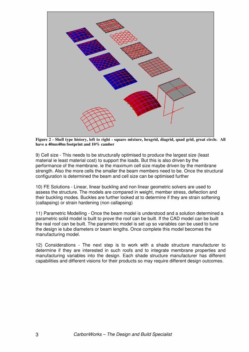
Figure 2 - Shell type history, left to right - square mixture, hexgrid, diagrid, quad grid, great circle. All
have a 40mx40m footprint and 10% camber
9) Cell size - This needs to be structurally optimised to produce the largest size (least material ie least material cost) to support the loads. But this is also driven by the performance of the membrane. ie the maximum cell size maybe driven by the membrane strength. Also the more cells the smaller the beam members need to be. Once the structural configuration is determined the beam and cell size can be optimised further 10) FE Solutions - Linear, linear buckling and non linear geometric solvers are used to assess the structure. The models are compared in weight, member stress, deflection and their buckling modes. Buckles are further looked at to determine if they are strain softening (callapsing) or strain hardening (non callapsing) 11) Parametric Modelling - Once the beam model is understood and a solution determined a parametric solid model is built to prove the roof can be built. If the CAD model can be built the real roof can be built. The parametric model is set up so variables can be used to tune the design ie tube diameters or beam lengths. Once complete this model becomes the manufacturing model. 12) Considerations - The next step is to work with a shade structure manufacturer to determine if they are interested in such roofs and to integrate membrane properties and manufacturing variables into the design. Each shade structure manufacturer has different capabilities and different visions for their products so may require different design outcomes.
CarbonWorks – The Design and Build Specialist 4
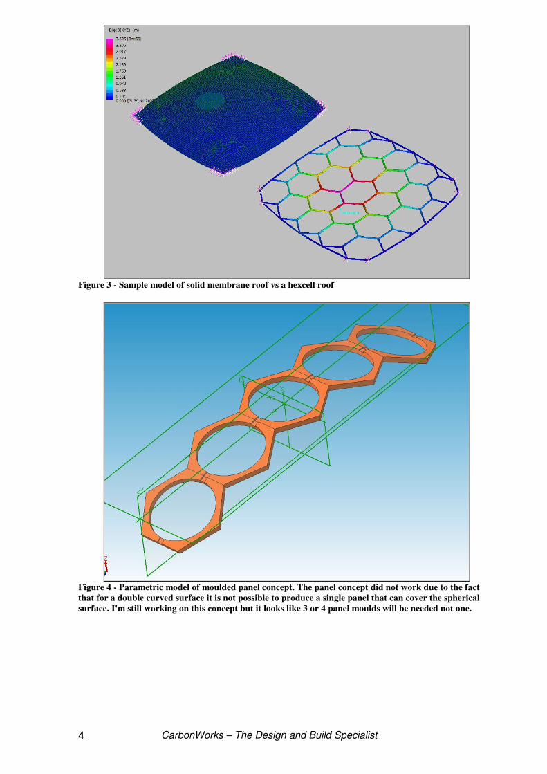
Figure 3 - Sample model of solid membrane roof vs a hexcell roof
Figure 4 - Parametric model of moulded panel concept. The panel concept did not work due to the fact
that for a double curved surface it is not possible to produce a single panel that can cover the spherical
surface. I'm still working on this concept but it looks like 3 or 4 panel moulds will be needed not one.
CarbonWorks – The Design and Build Specialist 5
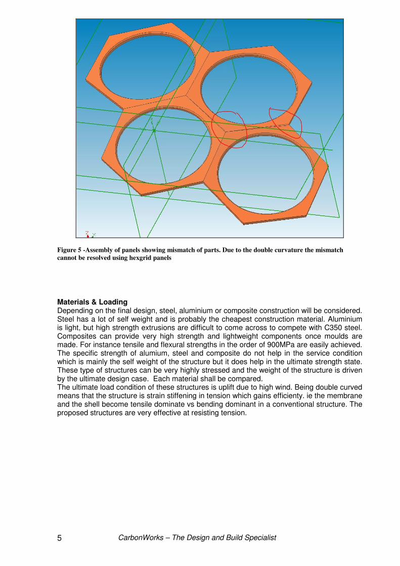
Figure 5 -Assembly of panels showing mismatch of parts. Due to the double curvature the mismatch
cannot be resolved using hexgrid panels
Materials & Loading Depending on the final design, steel, aluminium or composite construction will be considered. Steel has a lot of self weight and is probably the cheapest construction material. Aluminium is light, but high strength extrusions are difficult to come across to compete with C350 steel. Composites can provide very high strength and lightweight components once moulds are made. For instance tensile and flexural strengths in the order of 900MPa are easily achieved. The specific strength of alumium, steel and composite do not help in the service condition which is mainly the self weight of the structure but it does help in the ultimate strength state. These type of structures can be very highly stressed and the weight of the structure is driven by the ultimate design case. Each material shall be compared. The ultimate load condition of these structures is uplift due to high wind. Being double curved means that the structure is strain stiffening in tension which gains efficienty. ie the membrane and the shell become tensile dominate vs bending dominant in a conventional structure. The proposed structures are very effective at resisting tension.
CarbonWorks – The Design and Build Specialist 6
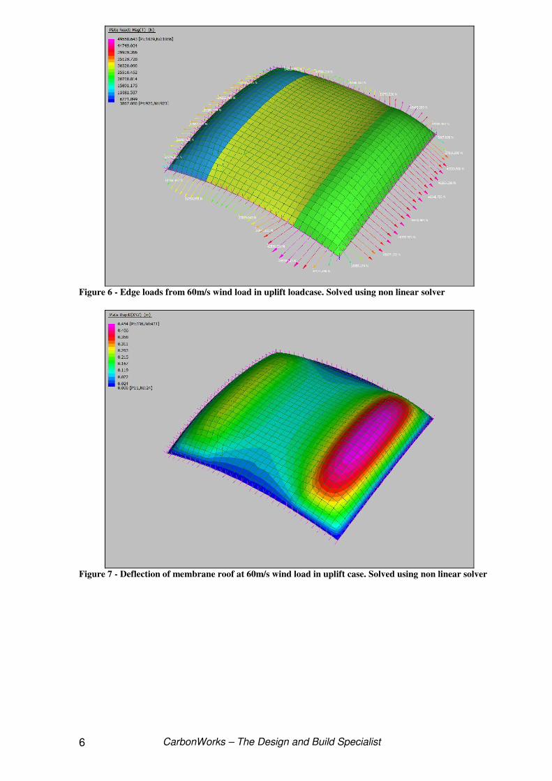
Figure 6 - Edge loads from 60m/s wind load in uplift loadcase. Solved using non linear solver
Figure 7 - Deflection of membrane roof at 60m/s wind load in uplift case. Solved using non linear solver

CarbonWorks – The Design and Build Specialist 7
Figure 8 - A Diagrid shell covering a bowling green.
Diagrid Discussion Traditionally this type of structure is complicated due to the type of connectors that have to be made. They are either welded to match each angle, or each element is bent to its required angle. All of these angles have to be very accurate otherwise the structure does not assemble. CarbonWorks proposes to use a flat fibreglass connector that allows itself to be bent to the required angle at assembly. This is sometimes called a living hinge or a flex plate. High performance race cars have used flex plates to replace universal joints and suspension joints for decades. In this case it would be in static conditions not the highly loaded dynamic cases just mentioned. CarbonWorks designed a flex plate hinge for a jetty system that has outperformed its metal predecessors. Metal hinges were failing in under 12 months of service. The fibreglass flex plates are still going strong, flexing at 10degs each tide cycle for over three years. In our roofs case the flex would be minimal. The maximum angle needed is 7degs. The beams themselves would be aluminium or fibreglass tubes with bonded bolting fittings or sockets at the ends. Each beam would be cut to the correct length and assembled. Its envisaged that assembly could be done on the ground from the ground up. Starting at the centre beams and working out to the perimeter beams. Diagrid construction is also suited to rectangular and square floorplans, something domes and isogrids are not good at.
CarbonWorks – The Design and Build Specialist 8
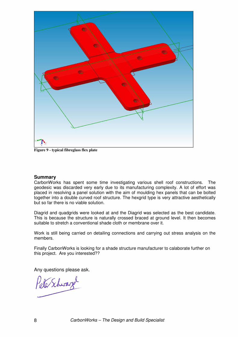
Figure 9 - typical fibreglass flex plate
Summary CarbonWorks has spent some time investigating various shell roof constructions. The geodesic was discarded very early due to its manufacturing complexity. A lot of effort was placed in resolving a panel solution with the aim of moulding hex panels that can be bolted together into a double curved roof structure. The hexgrid type is very attractive aesthetically but so far there is no viable solution. Diagrid and quadgrids were looked at and the Diagrid was selected as the best candidate. This is because the structure is naturally crossed braced at ground level. It then becomes suitable to stretch a conventional shade cloth or membrane over it. Work is still being carried on detailing connections and carrying out stress analysis on the members. Finally CarbonWorks is looking for a shade structure manufacturer to calaborate further on this project. Are you interested??
Any questions please ask.

CarbonWorks – The Design and Build Specialist 9
80mx40m test structure