90 AM RANGE - MODULAR CONTACTORS CTR - GRUPO … EDINMCCTR.pdf · 4 90 AM RANGE MODULAR CONTACTORS...
20
90 AM RANGE - MODULAR CONTACTORS CTR ENERGY DIN
Transcript of 90 AM RANGE - MODULAR CONTACTORS CTR - GRUPO … EDINMCCTR.pdf · 4 90 AM RANGE MODULAR CONTACTORS...
90 AM RANGE - MODULAR CONTACTORS CTR
energy DIn
2
90 AM RANGE
MODULAR CONTACTORS CTR
90
AM
RA
NG
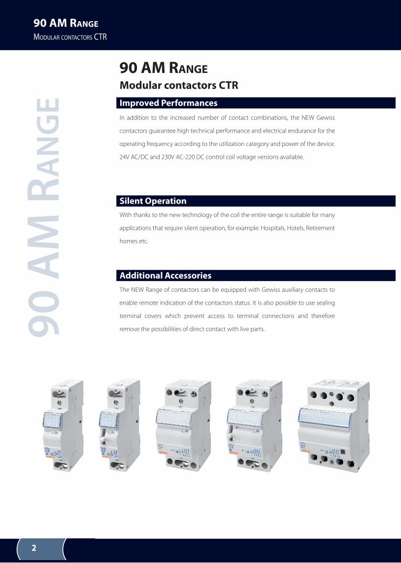
E Improved Performances
In addition to the increased number of contact combinations, the NEW Gewiss
contactors guarantee high technical performance and electrical endurance for the
operating frequency according to the utilization category and power of the device.
24V AC/DC and 230V AC-220 DC control coil voltage versions available.
Additional Accessories
The NEW Range of contactors can be equipped with Gewiss auxiliary contacts to
enable remote indication of the contactors status. It is also possible to use sealing
terminal covers which prevent access to terminal connections and therefore
remove the possibilities of direct contact with live parts.
90 AM RANGE
Silent Operation
With thanks to the new technology of the coil the entire range is suitable for many
applications that require silent operation, for example: Hospitals, Hotels, Retirement
homes etc.
M odular contactors CTR
3
90 AM RANGE
MODULAR CONTACTORS CTR
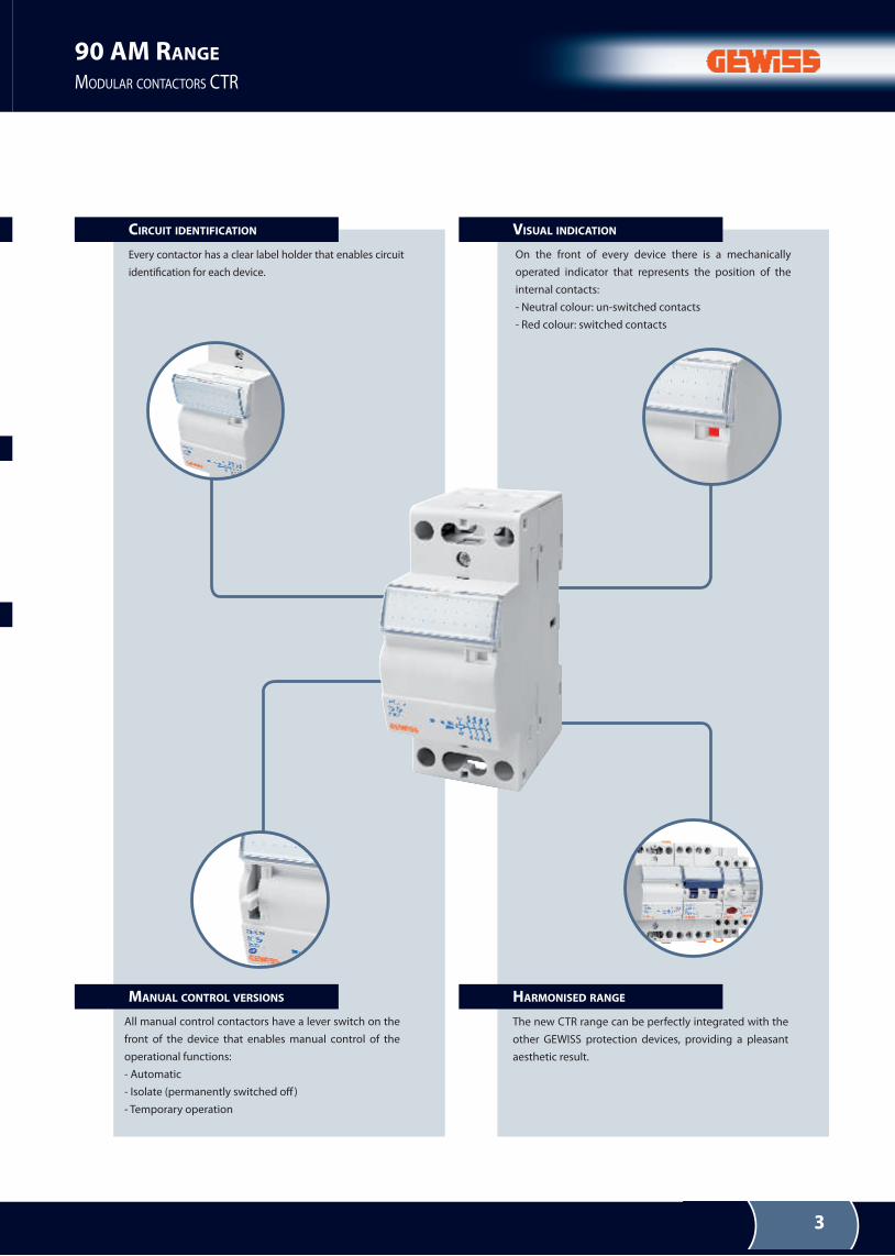
CIRCUIT IDENTIFICATION
every contactor has a clear label holder that enables circuit
identiication for each device.
MANUAL CONTROL VERSIONS
On the front of every device there is a mechanically
operated indicator that represents the position of the
internal contacts:
- neutral colour: un-switched contacts
- red colour: switched contacts
HARMONISED RANGE
The new CTr range can be perfectly integrated with the
other geWISS protection devices, providing a pleasant
aesthetic result.
VISUAL INDICATION
All manual control contactors have a lever switch on the
front of the device that enables manual control of the
operational functions:
- Automatic
- Isolate (permanently switched of)
- Temporary operation
4
90 AM RANGE
MODULAR CONTACTORS CTR
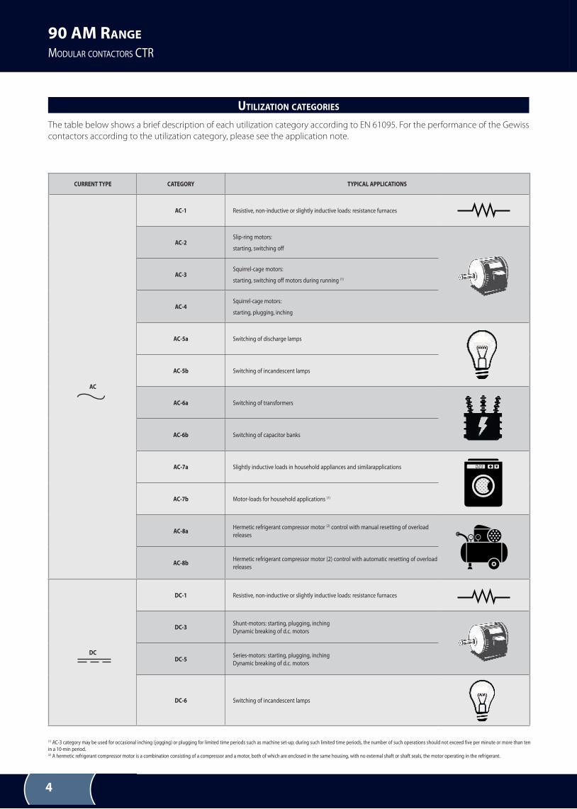
CURRENT TYPE CATEGORY TYPICAL APPLICATIONS
AC
AC-1 resistive, non-inductive or slightly inductive loads: resistance furnaces
AC-2Slip-ring motors:
starting, switching off
AC-3Squirrel-cage motors:
starting, switching off motors during running (1)
AC-4Squirrel-cage motors:
starting, plugging, inching
AC-5a Switching of discharge lamps
AC-5b Switching of incandescent lamps
AC-6a Switching of transformers
AC-6b Switching of capacitor banks
AC-7a Slightly inductive loads in household appliances and similarapplications
AC-7b Motor-loads for household applications (1)
AC-8aHermetic refrigerant compressor motor (2) control with manual resetting of overload
releases
AC-8bHermetic refrigerant compressor motor (2) control with automatic resetting of overload
releases
DC
DC-1 resistive, non-inductive or slightly inductive loads: resistance furnaces
DC-3Shunt-motors: starting, plugging, inching
Dynamic breaking of d.c. motors
DC-5Series-motors: starting, plugging, inching
Dynamic breaking of d.c. motors
DC-6 Switching of incandescent lamps
(1) AC-3 category may be used for occasional inching (jogging) or plugging for limited time periods such as machine set-up; during such limited time periods, the number of such operations should not exceed five per minute or more than ten
in a 10-min period.(2) A hermetic refrigerant compressor motor is a combination consisting of a compressor and a motor, both of which are enclosed in the same housing, with no external shaft or shaft seals, the motor operating in the refrigerant.
The table below shows a brief description of each utilization category according to EN 61095. For the performance of the Gewiss
contactors according to the utilization category, please see the application note.
UTILIZATION CATEGORIES
5
90 AM RANGE
MODULAR CONTACTORS CTR
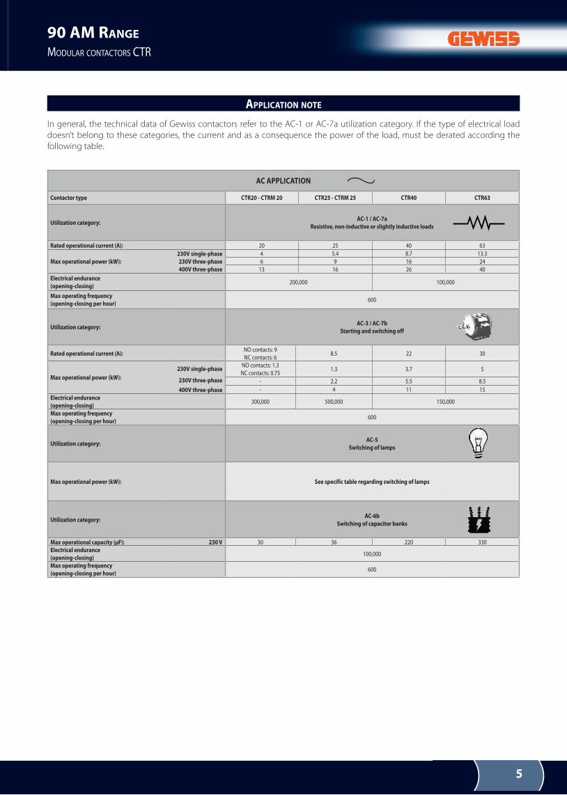
In general, the technical data of Gewiss contactors refer to the AC-1 or AC-7a utilization category. If the type of electrical load
doesn’t belong to these categories, the current and as a consequence the power of the load, must be derated according the
following table.
AC APPLICATION
Contactor type CTR20 - CTRM 20 CTR25 - CTRM 25 CTR40 CTR63
Utilization category:AC-1 / AC-7a
Resistive, non-inductive or slightly inductive loads
Rated operational current (A): 20 25 40 63
Max operational power (kW):
230V single-phase
230V three-phase
400V three-phase
4 5.4 8.7 13.3
6 9 16 24
13 16 26 40
Electrical endurance
(opening-closing)200,000 100,000
Max operating frequency
(opening-closing per hour)600
Utilization category:AC-3 / AC-7b
Starting and switching off
Rated operational current (A):nO contacts: 9
nC contacts: 68.5 22 30
Max operational power (kW):
230V single-phase
230V three-phase
400V three-phase
nO contacts: 1.3
nC contacts: 0.751.3 3.7 5
- 2.2 5.5 8.5
- 4 11 15
Electrical endurance
(opening-closing)300,000 500,000 150,000
Max operating frequency
(opening-closing per hour)600
Utilization category:AC-5
Switching of lamps
Max operational power (kW): See specific table regarding switching of lamps
Utilization category:AC-6b
Switching of capacitor banks
Max operational capacity (μF): 230 V 30 36 220 330
Electrical endurance
(opening-closing)100,000
Max operating frequency
(opening-closing per hour)600
APPLICATION NOTE
6
90 AM RANGE
MODULAR CONTACTORS CTR
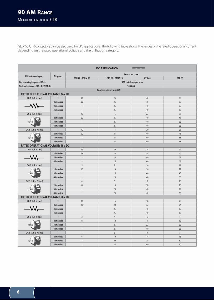
DC APPLICATION
Utilization category Nr. polesContactor type
CTR 20 - CTRM 20 CTR 25 - CTRM 25 CTR 40 CTR 63
Max operating frequency (DC-1): 300 switching per hour
Electrical endurance (DC-1/DC-3/DC-5): 100.000
Rated operational current (A)
RATED OPERATIONAL VOLTAGE: 24V DC
DC-1 (L/R ≤ 1ms) 1 20 25 40 63
2 in series 20 25 40 63
3 in series - 25 40 63
4 in series - 25 40 63
DC-3 (L/R ≤ 2ms) 1 10 15 22 25
2 in series 20 25 40 45
3 in series - 25 40 63
4 in series - 25 40 63
DC-5 (L/R ≤ 7,5ms) 1 10 15 20 25
2 in series 20 25 40 45
3 in series - 25 40 63
4 in series - 25 40 63
RATED OPERATIONAL VOLTAGE: 48V DCDC-1 (L/R ≤ 1ms) 1 15 20 24 26
2 in series 18 25 38 42
3 in series - 25 40 63
4 in series - 25 40 63
DC-3 (L/R ≤ 2ms) 1 5 8 10 11
2 in series 10 16 20 22
3 in series - 25 40 45
4 in series - 25 40 63
DC-5 (L/R ≤ 7,5ms) 1 4 5 8 10
2 in series 8 15 18 20
3 in series - 25 40 44
4 in series - 25 40 63
RATED OPERATIONAL VOLTAGE: 60V DC
DC-1 (L/R ≤ 1ms) 1 10 15 18 20
2 in series 15 20 32 34
3 in series - 25 40 60
4 in series - 25 40 63
DC-3 (L/R ≤ 2ms) 1 2 4 5 5
2 in series 8 12 16 18
3 in series - 25 32 35
4 in series - 25 40 63
DC-5 (L/R ≤ 7,5ms) 1 1 3 4 5
2 in series 6 10 14 15
3 in series - 20 28 30
4 in series - 25 40 60
GEWISS CTR contactors can be also used for DC applications. The following table shows the values of the rated operational current
depending on the rated operational voltage and the utilization category.
7
90 AM RANGE
MODULAR CONTACTORS CTR
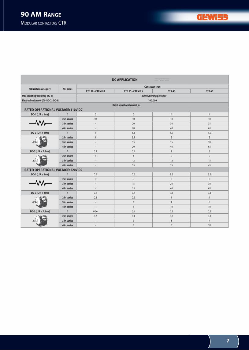
DC APPLICATION
Utilization category Nr. polesContactor type
CTR 20 - CTRM 20 CTR 25 - CTRM 25 CTR 40 CTR 63
Max operating frequency (DC-1): 300 switching per hour
Electrical endurance (DC-1/DC-3/DC-5): 100.000
Rated operational current (A)
RATED OPERATIONAL VOLTAGE: 110V DC
DC-1 (L/R ≤ 1ms) 1 6 6 4 4
2 in series 10 10 10 10
3 in series - 20 30 35
4 in series - 20 40 63
DC-3 (L/R ≤ 2ms) 1 1 1.3 1.5 1.5
2 in series 4 5.5 5 5
3 in series - 15 15 18
4 in series - 20 40 63
DC-5 (L/R ≤ 7,5ms) 1 0.3 0.5 1 1
2 in series 2 4 5 5
3 in series - 12 12 15
4 in series - 15 35 45
RATED OPERATIONAL VOLTAGE: 220V DCDC-1 (L/R ≤ 1ms) 1 0.6 0.6 1.2 1.2
2 in series 6 6 8 8
3 in series - 15 20 30
4 in series - 15 40 63
DC-3 (L/R ≤ 2ms) 1 0.1 0.2 0.3 0.3
2 in series 0.4 0.6 1 1
3 in series - 3 4 5
4 in series - 8 10 10
DC-5 (L/R ≤ 7,5ms) 1 0.06 0.1 0.2 0.2
2 in series 0.2 0.4 0.8 0.8
3 in series - 2 3 4
4 in series - 5 8 10
8
90 AM RANGE
MODULAR CONTACTORS CTR
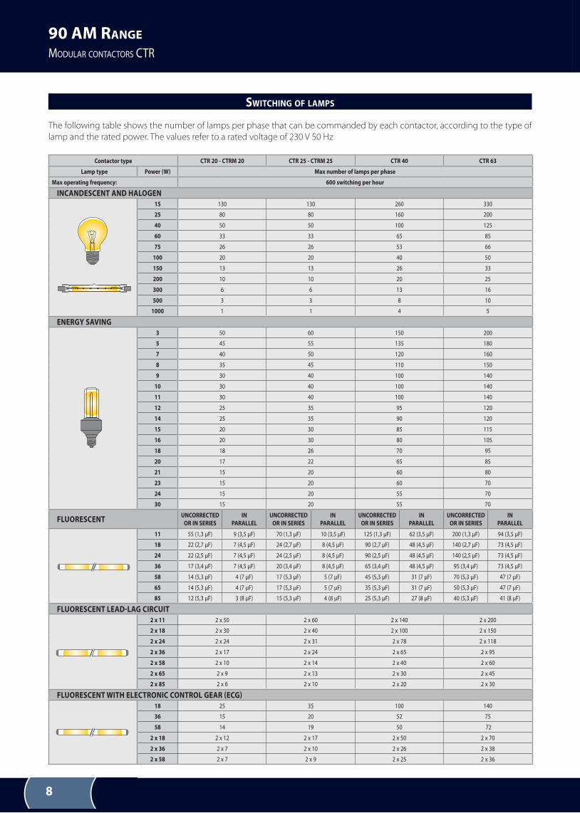
SWITCHING OF LAMPS
Contactor type CTR 20 - CTRM 20 CTR 25 - CTRM 25 CTR 40 CTR 63
Lamp type Power (W) Max number of lamps per phase
Max operating frequency: 600 switching per hour
INCANDESCENT AND HALOGEN
15 130 130 260 330
25 80 80 160 200
40 50 50 100 125
60 33 33 65 85
75 26 26 53 66
100 20 20 40 50
150 13 13 26 33
200 10 10 20 25
300 6 6 13 16
500 3 3 8 10
1000 1 1 4 5
ENERGY SAVING
3 50 60 150 200
5 45 55 135 180
7 40 50 120 160
8 35 45 110 150
9 30 40 100 140
10 30 40 100 140
11 30 40 100 140
12 25 35 95 120
14 25 35 90 120
15 20 30 85 115
16 20 30 80 105
18 18 26 70 95
20 17 22 65 85
21 15 20 60 80
23 15 20 60 70
24 15 20 55 70
30 15 20 55 70
FLUORESCENTUNCORRECTED
OR IN SERIES
IN
PARALLEL
UNCORRECTED
OR IN SERIES
IN
PARALLEL
UNCORRECTED
OR IN SERIES
IN
PARALLEL
UNCORRECTED
OR IN SERIES
IN
PARALLEL
11 55 (1,3 µF) 9 (3,5 µF) 70 (1,3 µF) 10 (3,5 µF) 125 (1,3 µF) 62 (3,5 µF) 200 (1,3 µF) 94 (3,5 µF)
18 22 (2,7 µF) 7 (4,5 µF) 24 (2,7 µF) 8 (4,5 µF) 90 (2,7 µF) 48 (4,5 µF) 140 (2,7 µF) 73 (4,5 µF)
24 22 (2,5 µF) 7 (4,5 µF) 24 (2,5 µF) 8 (4,5 µF) 90 (2,5 µF) 48 (4,5 µF) 140 (2,5 µF) 73 (4,5 µF)
36 17 (3,4 µF) 7 (4,5 µF) 20 (3,4 µF) 8 (4,5 µF) 65 (3,4 µF) 48 (4,5 µF) 95 (3,4 µF) 73 (4,5 µF)
58 14 (5,3 µF) 4 (7 µF) 17 (5,3 µF) 5 (7 µF) 45 (5,3 µF) 31 (7 µF) 70 (5,3 µF) 47 (7 µF)
65 14 (5,3 µF) 4 (7 µF) 17 (5,3 µF) 5 (7 µF) 35 (5,3 µF) 31 (7 µF) 50 (5,3 µF) 47 (7 µF)
85 12 (5,3 µF) 3 (8 µF) 15 (5,3 µF) 4 (8 µF) 25 (5,3 µF) 27 (8 µF) 40 (5,3 µF) 41 (8 µF)
FLUORESCENT LEAD-LAG CIRCUIT
2 x 11 2 x 50 2 x 60 2 x 140 2 x 200
2 x 18 2 x 30 2 x 40 2 x 100 2 x 150
2 x 24 2 x 24 2 x 31 2 x 78 2 x 118
2 x 36 2 x 17 2 x 24 2 x 65 2 x 95
2 x 58 2 x 10 2 x 14 2 x 40 2 x 60
2 x 65 2 x 9 2 x 13 2 x 30 2 x 45
2 x 85 2 x 6 2 x 10 2 x 20 2 x 30
FLUORESCENT WITH ELECTRONIC CONTROL GEAR (ECG)
18 25 35 100 140
36 15 20 52 75
58 14 19 50 72
2 x 18 2 x 12 2 x 17 2 x 50 2 x 70
2 x 36 2 x 7 2 x 10 2 x 26 2 x 38
2 x 58 2 x 7 2 x 9 2 x 25 2 x 36
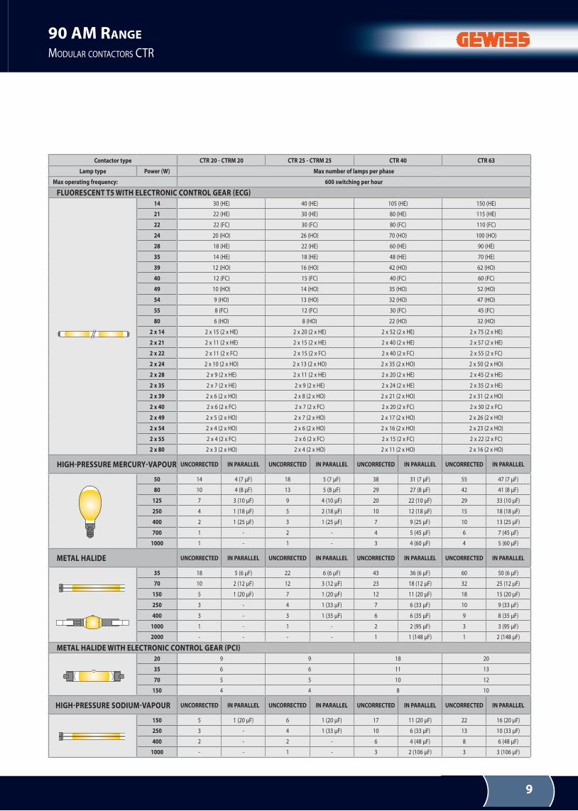
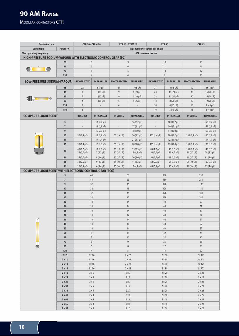
The following table shows the number of lamps per phase that can be commanded by each contactor, according to the type of
lamp and the rated power. The values refer to a rated voltage of 230 V 50 Hz
9
90 AM RANGE
MODULAR CONTACTORS CTR
Contactor type CTR 20 - CTRM 20 CTR 25 - CTRM 25 CTR 40 CTR 63
Lamp type Power (W) Max number of lamps per phase
Max operating frequency: 600 switching per hour
FLUORESCENT T5 WITH ELECTRONIC CONTROL GEAR (ECG)
14 30 (He) 40 (He) 105 (He) 150 (He)
21 22 (He) 30 (He) 80 (He) 115 (He)
22 22 (FC) 30 (FC) 80 (FC) 110 (FC)
24 20 (HO) 26 (HO) 70 (HO) 100 (HO)
28 18 (He) 22 (He) 60 (He) 90 (He)
35 14 (He) 18 (He) 48 (He) 70 (He)
39 12 (HO) 16 (HO) 42 (HO) 62 (HO)
40 12 (FC) 15 (FC) 40 (FC) 60 (FC)
49 10 (HO) 14 (HO) 35 (HO) 52 (HO)
54 9 (HO) 13 (HO) 32 (HO) 47 (HO)
55 8 (FC) 12 (FC) 30 (FC) 45 (FC)
80 6 (HO) 8 (HO) 22 (HO) 32 (HO)
2 x 14 2 x 15 (2 x He) 2 x 20 (2 x He) 2 x 52 (2 x He) 2 x 75 (2 x He)
2 x 21 2 x 11 (2 x He) 2 x 15 (2 x He) 2 x 40 (2 x He) 2 x 57 (2 x He)
2 x 22 2 x 11 (2 x FC) 2 x 15 (2 x FC) 2 x 40 (2 x FC) 2 x 55 (2 x FC)
2 x 24 2 x 10 (2 x HO) 2 x 13 (2 x HO) 2 x 35 (2 x HO) 2 x 50 (2 x HO)
2 x 28 2 x 9 (2 x He) 2 x 11 (2 x He) 2 x 20 (2 x He) 2 x 45 (2 x He)
2 x 35 2 x 7 (2 x He) 2 x 9 (2 x He) 2 x 24 (2 x He) 2 x 35 (2 x He)
2 x 39 2 x 6 (2 x HO) 2 x 8 (2 x HO) 2 x 21 (2 x HO) 2 x 31 (2 x HO)
2 x 40 2 x 6 (2 x FC) 2 x 7 (2 x FC) 2 x 20 (2 x FC) 2 x 30 (2 x FC)
2 x 49 2 x 5 (2 x HO) 2 x 7 (2 x HO) 2 x 17 (2 x HO) 2 x 26 (2 x HO)
2 x 54 2 x 4 (2 x HO) 2 x 6 (2 x HO) 2 x 16 (2 x HO) 2 x 23 (2 x HO)
2 x 55 2 x 4 (2 x FC) 2 x 6 (2 x FC) 2 x 15 (2 x FC) 2 x 22 (2 x FC)
2 x 80 2 x 3 (2 x HO) 2 x 4 (2 x HO) 2 x 11 (2 x HO) 2 x 16 (2 x HO)
HIGH-PRESSURE MERCURY-VAPOUR UNCORRECTED IN PARALLEL UNCORRECTED IN PARALLEL UNCORRECTED IN PARALLEL UNCORRECTED IN PARALLEL
50 14 4 (7 µF) 18 5 (7 µF) 38 31 (7 µF) 55 47 (7 µF)
80 10 4 (8 µF) 13 5 (8 µF) 29 27 (8 µF) 42 41 (8 µF)
125 7 3 (10 µF) 9 4 (10 µF) 20 22 (10 µF) 29 33 (10 µF)
250 4 1 (18 µF) 5 2 (18 µF) 10 12 (18 µF) 15 18 (18 µF)
400 2 1 (25 µF) 3 1 (25 µF) 7 9 (25 µF) 10 13 (25 µF)
700 1 - 2 - 4 5 (45 µF) 6 7 (45 µF)
1000 1 - 1 - 3 4 (60 µF) 4 5 (60 µF)
METAL HALIDE UNCORRECTED IN PARALLEL UNCORRECTED IN PARALLEL UNCORRECTED IN PARALLEL UNCORRECTED IN PARALLEL
35 18 5 (6 µF) 22 6 (6 µF) 43 36 (6 µF) 60 50 (6 µF)
70 10 2 (12 µF) 12 3 (12 µF) 23 18 (12 µF) 32 25 (12 µF)
150 5 1 (20 µF) 7 1 (20 µF) 12 11 (20 µF) 18 15 (20 µF)
250 3 - 4 1 (33 µF) 7 6 (33 µF) 10 9 (33 µF)
400 3 - 3 1 (35 µF) 6 6 (35 µF) 9 8 (35 µF)
1000 1 - 1 - 2 2 (95 µF) 3 3 (95 µF)
2000 - - - - 1 1 (148 µF) 1 2 (148 µF)
METAL HALIDE WITH ELECTRONIC CONTROL GEAR (PCI)
20 9 9 18 20
35 6 6 11 13
70 5 5 10 12
150 4 4 8 10
HIGH-PRESSURE SODIUM-VAPOUR UNCORRECTED IN PARALLEL UNCORRECTED IN PARALLEL UNCORRECTED IN PARALLEL UNCORRECTED IN PARALLEL
150 5 1 (20 µF) 6 1 (20 µF) 17 11 (20 µF) 22 16 (20 µF)
250 3 - 4 1 (33 µF) 10 6 (33 µF) 13 10 (33 µF)
400 2 - 2 - 6 4 (48 µF) 8 6 (48 µF)
1000 - - 1 - 3 2 (106 µF) 3 3 (106 µF)
10
90 AM RANGE
MODULAR CONTACTORS CTR
Contactor type CTR 20 - CTRM 20 CTR 25 - CTRM 25 CTR 40 CTR 63
Lamp type Power (W) Max number of lamps per phase
Max operating frequency: 600 manovre per ora
HIGH-PRESSURE SODIUM-VAPOUR WITH ELECTRONIC CONTROL GEAR (PCI)
20 9 9 18 20
35 6 6 11 13
70 5 5 10 12
150 4 4 8 10
LOW-PRESSURE SODIUM-VAPOUR UNCORRECTED IN PARALLEL UNCORRECTED IN PARALLEL UNCORRECTED IN PARALLEL UNCORRECTED IN PARALLEL
18 22 6 (5 µF) 27 7 (5 µF) 71 44 (5 µF) 90 66 (5 µF)
35 7 1 (20 µF) 9 1 (20 µF) 23 11 (20 µF) 30 16 (20 µF)
55 7 1 (20 µF) 9 1 (20 µF) 23 11 (20 µF) 30 16 (20 µF)
90 4 1 (26 µF) 5 1 (26 µF) 14 8 (26 µF) 19 12 (26 µF)
135 3 - 4 - 10 4 (45 µF) 13 7 (45 µF)
180 3 - 4 - 10 5 (40 µF) 13 8 (40 µF)
COMPACT FLUORESCENT IN SERIES IN PARALLEL IN SERIES IN PARALLEL IN SERIES IN PARALLEL IN SERIES IN PARALLEL
5 - 13 (2,2 µF) - 16 (2,2 µF) - 100 (2,2 µF) - 150 (2,2 µF)
7 - 14 (2,1 µF) - 17 (2,1 µF) - 104 (2,1 µF) - 157 (2,1 µF)
9 - 15 (2,0 µF) - 18 (2,0 µF) - 110 (2,0 µF) - 165 (2,0 µF)
10 50 (1,4 µF) 13 (2,2 µF) 60 (1,4 µF) 16 (2,2 µF) 105 (1,4 µF) 100 (2,2 µF) 165 (1,4 µF) 150 (2,2 µF)
11 - 17 (1,7 µF) - 21 (1,7 µF) - 125 (1,7 µF) - 194 (1,7 µF)
13 50 (1,4 µF) 16 (1,8 µF) 60 (1,4 µF) 20 (1,8 µF) 105 (1,4 µF) 120 (1,8 µF) 165 (1,4 µF) 183 (1,8 µF)
1840 (1,7 µF)
25 (2,7 µF)
13 (2,3 µF)
7 (4,2 µF)
50 (1,7 µF)
30 (2,7 µF)
15 (2,3 µF)
8 (4,2 µF)
85 (1,7 µF)
50 (2,7 µF)
95 (2,3 µF)
52 (4,2 µF)
135 (1,7 µF)
80 (2,7 µF)
143 (2,3 µF)
78 (4,2 µF)
24 25 (2,7 µF) 8 (3,6 µF) 30 (2,7 µF) 10 (3,6 µF) 50 (2,7 µF) 61 (3,6 µF) 80 (2,7 µF) 91 (3,6 µF)
26 30 (2,5 µF) 9 (3,3 µF) 35 (2,5 µF) 11 (3,3 µF) 60 (2,5 µF) 66 (3,3 µF) 95 (2,5 µF) 100 (3,3 µF)
36 20 (3,4 µF) 6 (4,4 µF) 25 (3,4 µF) 8 (4,4 µF) 45 (3,4 µF) 50 (4,4 µF) 70 (3,4 µF) 75 (4,4 µF)
COMPACT FLUORESCENT WITH ELECTRONIC CONTROL GEAR (ECG)
5 45 63 180 250
7 45 63 180 250
9 32 45 128 180
10 32 45 128 180
11 32 45 128 180
13 32 45 128 180
18 10 14 40 57
24 10 14 40 57
26 10 14 40 57
32 10 14 40 57
36 10 14 40 57
40 10 14 40 57
42 10 14 40 57
55 8 11 32 45
57 8 11 32 45
70 6 9 25 36
80 5 8 22 30
120 4 5 15 22
2 x 9 2 x 16 2 x 22 2 x 90 2 x 125
2 x 10 2 x 16 2 x 22 2 x 90 2 x 125
2 x 11 2 x 16 2 x 22 2 x 90 2 x 125
2 x 13 2 x 16 2 x 22 2 x 90 2 x 125
2 x 18 2 x 5 2 x 7 2 x 20 2 x 28
2 x 24 2 x 5 2 x 7 2 x 20 2 x 28
2 x 26 2 x 5 2 x 7 2 x 20 2 x 28
2 x 32 2 x 5 2 x 7 2 x 20 2 x 28
2 x 36 2 x 5 2 x 7 2 x 20 2 x 28
2 x 40 2 x 4 2 x 6 2 x 18 2 x 26
2 x 42 2 x 4 2 x 6 2 x 18 2 x 26
2 x 55 2 x 3 2 x 5 2 x 16 2 x 22
2 x 57 2 x 3 2 x 5 2 x 16 2 x 22
11
90 AM RANGE
MODULAR CONTACTORS CTR
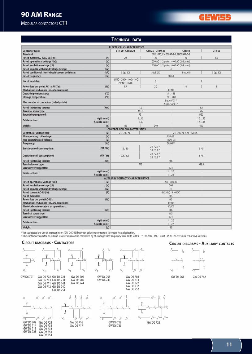
TECHNICAL DATA
ELECTRICAL CHARACTERISTICS
Contactor type: CTR 20 - CTRM 20 CTR 25 - CTRM 25 CTR 40 CTR 63
Standard: en 61095, en 60947-4-1, en60947-5-1
Rated current AC-1/AC-7a (In): (A) 20 25 40 63
Rated operational voltage (Ue): (V) 230 AC (1-2 poles) - 400 AC (3-4poles)
Rated insulation voltage (Ui): (V) 230 AC (1-2 poles) - 440 AC (3-4poles)
Rated impulse withstand voltage (Uimp): (kV) 4
Rated conditional short-circuit current with fuse: (kA) 3 (gL 20) 3 (gL 25) 3 (gL 63) 3 (gL 80)
Rated frequency: (Hz) 50/60
No. of modules:1 (1nO - 2nO - 1nO+1nC)
2 (3nO - 4nO)2 3
Power loss per pole ( AC-1 / AC-7a): (W) 1.7 2.2 4 8
Mechanical endurance (no. of operations): 3 x 10⁶
Operating temperature: (°C) -5…+55
Storage temperature: (°C) -30…+80
Max number of contactors (side-by-side):3 (≤ 40 °C) (1)
2 (40 - 55 °C) (1)
Rated tightening torque: (Nm) 1.2 3.5
Terminal screw type: M3.5 M5
Screwdriver suggested: PZ1 PZ2
Cable section:rigid (mm2)
flexible (mm2)
1...10
1...6
1.5…25
1.5…16
Weight (g) 130 240 420
CONTROL COIL CHARACTERISTICS
Control coil voltage (Uc): (V) 24 - 230 AC 24 - 230 AC / 24 - 220 DC
Min operating coil voltage: (V) 85% Uc
Max operating coil voltage: (V) 110% Uc
Frequency: (Hz) 50/60 (2)
Switch-on coil consumption: (VA / W) 12 / 102.6 / 2.6 (3)
3.8 / 3.8 (4) 5 / 5
Operation coil consumption: (VA / W) 2.8 / 1.22.6 / 2.6 (3)
3.8 / 3.8 (4) 5 / 5
Rated tightening torque: (Nm) 0.6
Terminal screw type: M3 M3.5
Screwdriver suggested: PZ1
Cable section:rigid (mm2)
flexible (mm2)1…2.5
1…2.5
AUxILIARY CONTACT CHARACTERISTICS
Rated operational voltage (Ue): (V) 230 - 400 AC
Rated insulation voltage (Ui): (V) 500
Rated impulse withstand voltage (Uimp): (kV) 4
Rated current AC-15 (In): (A) 6 (230V) - 4 (400V)
No. of modules: 0.5
Power loss per pole (AC-15): (W) 0.3
Mechanical endurance (no. of operations): 3 x 10⁶
Electrical endurance (no. of operations): 50,000
Rated tightening torque: (Nm) 0.6
Terminal screw type: M3
Screwdriver suggested: PZ1
Cable section:rigid (mm2)
flexible (mm2)
1…2.5
1…2.5
Weight (g) 35
(1) It’s suggested the use of a spacer insert (gW D6 766) between adjacent contactors to ensure heat dissipation. (2) The contactors’ coils for 25, 40 and 63A versions can be controlled by AC voltage with frequency from 40 to 500Hz (3) For 2nO - 3nO - 4nO - 3nA+1nC versions (4) For 4nC versions
CIRCUIT DIAGRAMS - CONTACTORS
gW D6 701 gW D6 706gW D6 707gW D6 744
gW D6 705gW D6 743
gW D6 708gW D6 713gW D6 722gW D6 732gW D6 752
gW D6 709gW D6 714gW D6 715gW D6 723
gW D6 724gW D6 733gW D6 734gW D6 753gW D6 754
gW D6 716gW D6 717
gW D6 718gW D6 735
gW D6 725
gW D6 761 gW D6 762
CIRCUIT DIAGRAMS - AUXILIARY CONTACTS
gW D6 702gW D6 703gW D6 711gW D6 712
gW D6 721gW D6 731gW D6 741gW D6 742gW D6 751
12
90 AM RANGE
MODULAR CONTACTORS CTR
K1
K1
K1
STOP
START
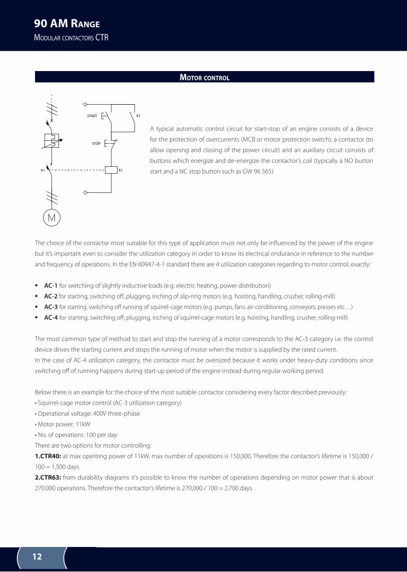
A typical automatic control circuit for start-stop of an engine consists of a device
for the protection of overcurrents (MCB or motor protection switch), a contactor (to
allow opening and closing of the power circuit) and an auxiliary circuit consists of
buttons which energize and de-energize the contactor’s coil (typically a NO button
start and a NC stop button such as GW 96 565)
The choice of the contactor most suitable for this type of application must not only be inluenced by the power of the engine
but it’s important even to consider the utilization category in order to know its electrical endurance in reference to the number
and frequency of operations. In the EN 60947-4-1 standard there are 4 utilization categories regarding to motor control, exactly:
• AC-1 for switching of slightly inductive loads (e.g. electric heating, power distribution)
• AC-2 for starting, switching of, plugging, inching of slip-ring motors (e.g. hoisting, handling, crusher, rolling-mill)
• AC-3 for starting, switching of running of squirrel-cage motors (e.g. pumps, fans, air-conditioning, conveyors, presses etc…)
• AC-4 for starting, switching of, plugging, inching of squirrel-cage motors (e.g. hoisting, handling, crusher, rolling-mill)
The most common type of method to start and stop the running of a motor corresponds to the AC-3 category i.e. the control
device drives the starting current and stops the running of motor when the motor is supplied by the rated current.
In the case of AC-4 utilization category, the contactor must be oversized because it works under heavy-duty conditions since
switching of of running happens during start-up period of the engine instead during regular working period.
Below there is an example for the choice of the most suitable contactor considering every factor described previously:
• Squirrel-cage motor control (AC-3 utilization category)
• Operational voltage: 400V three-phase
• Motor power: 11kW
• No. of operations: 100 per day
There are two options for motor controlling:
1.CTR40: at max operiting power of 11kW, max number of operations is 150,000. Therefore the contactor’s lifetime is 150,000 /
100 = 1,500 days.
2.CTR63: from durability diagrams it’s possible to know the number of operations depending on motor power that is about
270.000 operations. Therefore the contactor’s lifetime is 270,000 / 100 = 2,700 days.
MOTOR CONTROL
13
90 AM RANGE
MODULAR CONTACTORS CTR
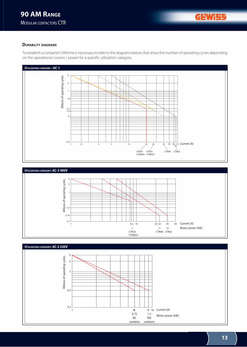
UTILIZATION CATEGORY : AC-1
UTILIZATION CATEGORY: AC-3 400V
UTILIZATION CATEGORY: AC-3 230V
CTR20
CTRM20
CTR25
CTRM25
CTR40 CTR63
CTR25
CTRM25
CTR40 CTR63
contatti
NA
contatti
NC
DURABILITY DIAGRAMS
Mili
on
s o
f o
per
atin
g c
ycle
sM
ilio
ns
of
op
erat
ing
cyc
les
Mili
on
s o
f o
per
atin
g c
ycle
s
Current (A)
Current (A)
Current (A)
1.3
nO
contacts
0.75
nC
contacts
Motor power (kW)
Motor power (kW)
To establish a contactor’s lifetime is necessary to refer to the diagrams below, that show the number of operating cycles depending
on the operational current / power for a speciic utilization category.
14
90 AM RANGE
MODULAR CONTACTORS CTR
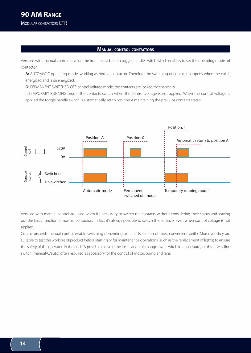
Versions with manual control have on the front face a built-in toggle handle switch which enables to set the operating mode of
contactor.
A: AUTOMATIC operating mode, working as normal contactor. Therefore the switching of contacts happens when the coil is
energized and is disenergized.
O: PERMANENT SWITCHED OFF control voltage mode, the contacts are locked mechanically.
I: TEMPORARY RUNNING mode. The contacts switch when the control voltage is not applied. When the control voltage is
applied the toggle handle switch is automatically set to position A maintaining the previuos contacts status.
Versions with manual control are used when it’s necessary to switch the contacts without considering their status and leaving
out the basic function of normal contactors. In fact it’s always possible to switch the contacts even when control voltage is not
applied.
Contactors with manual control enable switching depending on tarif (selection of most convenient tarif ). Moreover they are
suitable to test the working of product before starting or for maintenance operations (such as the replacement of lights) to ensure
the safety of the operator. In the end it’s possible to avoid the installation of change-over switch (manual/auto) or three-way line
switch (manual/0/auto) often required as accessory for the control of motor, pump and fans.
MANUAL CONTROL CONTACTORS
Co
ntr
ol
coil
Co
nta
cts
sta
tus
230V
Position: A Position: 0
Position: I
Automatic return to position A
Automatic mode Permanent
switched of mode
Temporary running mode
Switched
0V
Un-switched
15
90 AM RANGE
MODULAR CONTACTORS CTR
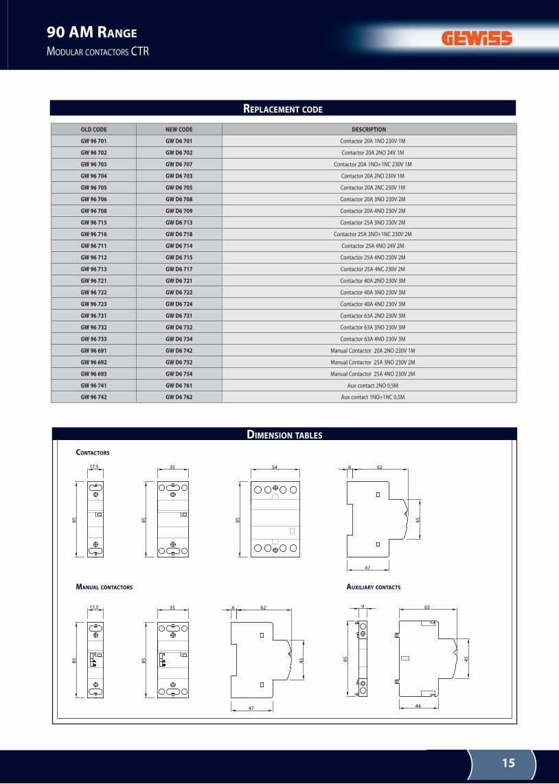
DIMENSION TABLES
17,5
85
6 62
47
45
35
85
54
85
65
44
45
9
85
17,5
85
35
85
6 62
47
45
CONTACTORS
AUXILIARY CONTACTSMANUAL CONTACTORS
OLD CODE NEW CODE DESCRIPTION
GW 96 701 GW D6 701 Contactor 20A 1nO 230V 1M
GW 96 702 GW D6 702 Contactor 20A 2nO 24V 1M
GW 96 703 GW D6 707 Contactor 20A 1nO+1nC 230V 1M
GW 96 704 GW D6 703 Contactor 20A 2nO 230V 1M
GW 96 705 GW D6 705 Contactor 20A 2nC 230V 1M
GW 96 706 GW D6 708 Contactor 20A 3nO 230V 2M
GW 96 708 GW D6 709 Contactor 20A 4nO 230V 2M
GW 96 715 GW D6 713 Contactor 25A 3nO 230V 2M
GW 96 716 GW D6 718 Contactor 25A 3nO+1nC 230V 2M
GW 96 711 GW D6 714 Contactor 25A 4nO 24V 2M
GW 96 712 GW D6 715 Contactor 25A 4nO 230V 2M
GW 96 713 GW D6 717 Contactor 25A 4nC 230V 2M
GW 96 721 GW D6 721 Contactor 40A 2nO 230V 3M
GW 96 722 GW D6 722 Contactor 40A 3nO 230V 3M
GW 96 723 GW D6 724 Contactor 40A 4nO 230V 3M
GW 96 731 GW D6 731 Contactor 63A 2nO 230V 3M
GW 96 732 GW D6 732 Contactor 63A 3nO 230V 3M
GW 96 733 GW D6 734 Contactor 63A 4nO 230V 3M
GW 96 691 GW D6 742 Manual Contactor 20A 2nO 230V 1M
GW 96 692 GW D6 752 Manual Contactor 25A 3nO 230V 2M
GW 96 693 GW D6 754 Manual Contactor 25A 4nO 230V 2M
GW 96 741 GW D6 761 Aux contact 2nO 0,5M
GW 96 742 GW D6 762 Aux contact 1nO+1nC 0,5M
REPLACEMENT CODE
16
90 AM RANGE
MODULAR CONTACTORS CTR
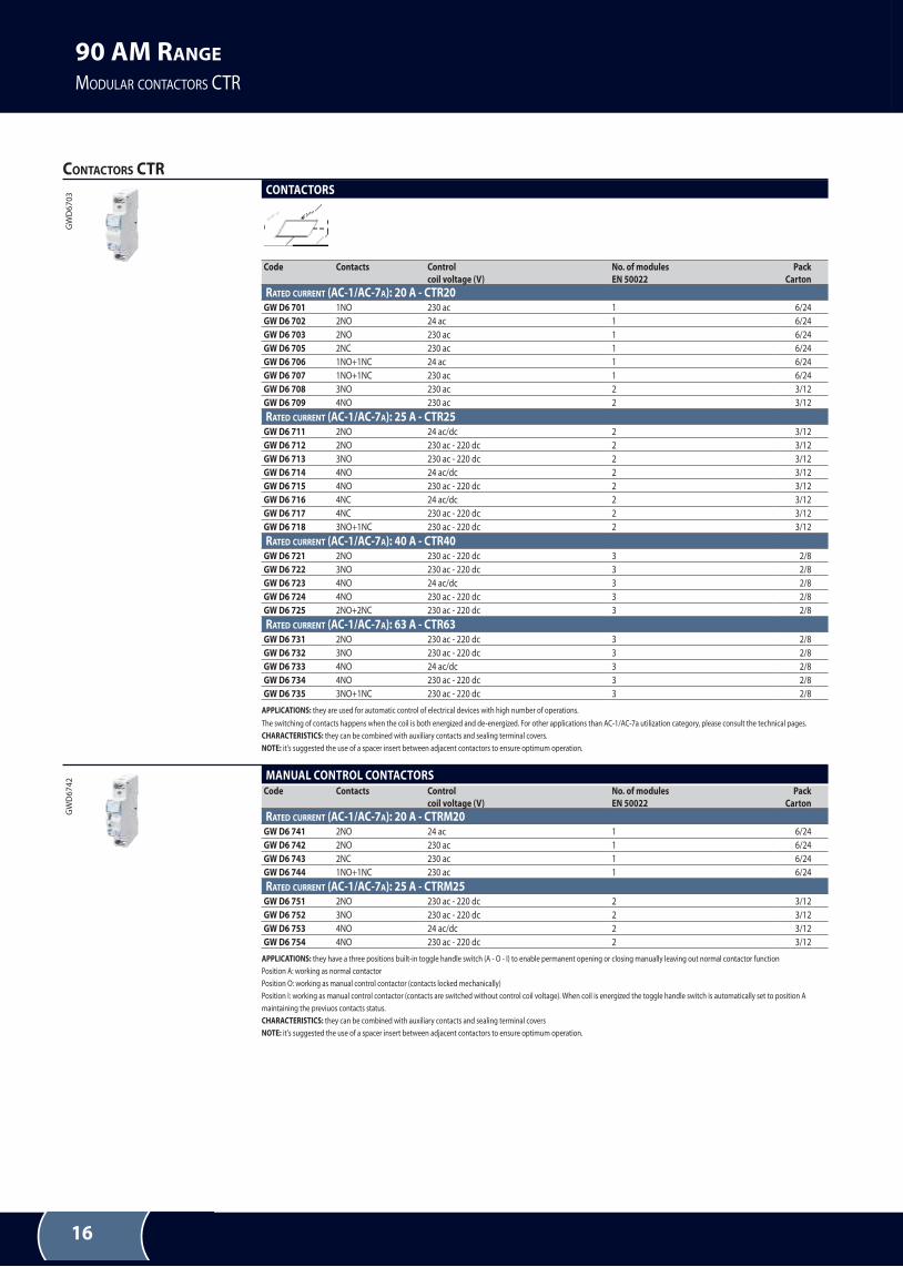
CONTACTORS CTR
gW
D6
70
3 CONTACTORS
Code Contacts Control
coil voltage (V)
No. of modules
EN 50022
Pack
Carton
RATED CURRENT (AC-1/AC-7A): 20 A - CTR20
GW D6 701 1nO 230 ac 1 6/24
GW D6 702 2nO 24 ac 1 6/24
GW D6 703 2nO 230 ac 1 6/24
GW D6 705 2nC 230 ac 1 6/24
GW D6 706 1nO+1nC 24 ac 1 6/24
GW D6 707 1nO+1nC 230 ac 1 6/24
GW D6 708 3nO 230 ac 2 3/12
GW D6 709 4nO 230 ac 2 3/12
RATED CURRENT (AC-1/AC-7A): 25 A - CTR25
GW D6 711 2nO 24 ac/dc 2 3/12
GW D6 712 2nO 230 ac - 220 dc 2 3/12
GW D6 713 3nO 230 ac - 220 dc 2 3/12
GW D6 714 4nO 24 ac/dc 2 3/12
GW D6 715 4nO 230 ac - 220 dc 2 3/12
GW D6 716 4nC 24 ac/dc 2 3/12
GW D6 717 4nC 230 ac - 220 dc 2 3/12
GW D6 718 3nO+1nC 230 ac - 220 dc 2 3/12
RATED CURRENT (AC-1/AC-7A): 40 A - CTR40
GW D6 721 2nO 230 ac - 220 dc 3 2/8
GW D6 722 3nO 230 ac - 220 dc 3 2/8
GW D6 723 4nO 24 ac/dc 3 2/8
GW D6 724 4nO 230 ac - 220 dc 3 2/8
GW D6 725 2nO+2nC 230 ac - 220 dc 3 2/8
RATED CURRENT (AC-1/AC-7A): 63 A - CTR63
GW D6 731 2nO 230 ac - 220 dc 3 2/8
GW D6 732 3nO 230 ac - 220 dc 3 2/8
GW D6 733 4nO 24 ac/dc 3 2/8
GW D6 734 4nO 230 ac - 220 dc 3 2/8
GW D6 735 3nO+1nC 230 ac - 220 dc 3 2/8
APPLICATIONS: they are used for automatic control of electrical devices with high number of operations.
The switching of contacts happens when the coil is both energized and de-energized. For other applications than AC-1/AC-7a utilization category, please consult the technical pages.
CHARACTERISTICS: they can be combined with auxiliary contacts and sealing terminal covers.
NOTE: it's suggested the use of a spacer insert between adjacent contactors to ensure optimum operation.
gW
D6
74
2 MANUAL CONTROL CONTACTORSCode Contacts Control
coil voltage (V)
No. of modules
EN 50022
Pack
Carton
RATED CURRENT (AC-1/AC-7A): 20 A - CTRM20
GW D6 741 2nO 24 ac 1 6/24
GW D6 742 2nO 230 ac 1 6/24
GW D6 743 2nC 230 ac 1 6/24
GW D6 744 1nO+1nC 230 ac 1 6/24
RATED CURRENT (AC-1/AC-7A): 25 A - CTRM25
GW D6 751 2nO 230 ac - 220 dc 2 3/12
GW D6 752 3nO 230 ac - 220 dc 2 3/12
GW D6 753 4nO 24 ac/dc 2 3/12
GW D6 754 4nO 230 ac - 220 dc 2 3/12
APPLICATIONS: they have a three positions built-in toggle handle switch (A - O - I) to enable permanent opening or closing manually leaving out normal contactor function
Position A: working as normal contactor
Position O: working as manual control contactor (contacts locked mechanically)
Position I: working as manual control contactor (contacts are switched without control coil voltage). When coil is energized the toggle handle switch is automatically set to position A
maintaining the previuos contacts status.
CHARACTERISTICS: they can be combined with auxiliary contacts and sealing terminal covers
NOTE: it's suggested the use of a spacer insert between adjacent contactors to ensure optimum operation.
17
90 AM RANGE
MODULAR CONTACTORS CTR
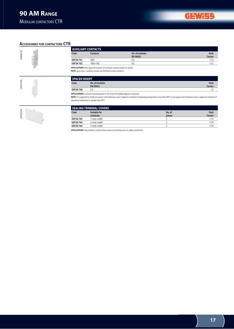
ACCESSORIES FOR CONTACTORS CTR
gW
D6
76
1 AUxILIARY CONTACTSCode Contacts No. of modules
EN 50022
Pack
Carton
GW D6 761 2nO 0.5 1/12
GW D6 762 1nO+1nC 0.5 1/12
APPLICATIONS: they signal the position of contactor contacts (open or closed).
NOTE: up to max. 1 auxiliary contact can be itted to each contactor.
gW
D6
76
6 SPACER INSERTCode No. of modules
EN 50022
Pack
Carton
GW D6 766 0.5 12
APPLICATIONS: it ensures heat dissipation in the event of installed adjacent contactors.
NOTE: it's suggested to install one spacer insert between every 3 adjacent contactors if operating temperature is less than 40°C or one spacer insert between every 2 adjacent contactors if
operating temperature is greater than 40°C.
gW
D6
76
4 SEALING TERMINAL COVERSCode Suitable for
contactor
No. of
pieces
Pack
Carton
GW D6 763 1 mod. width 2 1/10
GW D6 764 2 mod. width 2 1/10
GW D6 765 3 mod. width 2 1/10
APPLICATIONS: they enable to seal terminal screws, preventing access to cable connections.
18
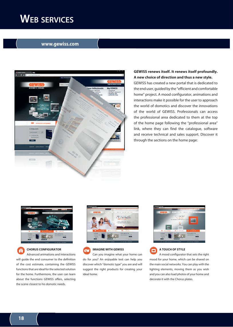
GEWISS renews itself. It renews itself profoundly.
A new choice of direction and thus a new style.
geWISS has created a new portal that is dedicated to
the end user, guided by the “efficient and comfortable
home” project. A mood configurator, animations and
interactions make it possible for the user to approach
the world of domotics and discover the innovations
of the world of geWISS. Professionals can access
the professional area dedicated to them at the top
of the home page following the “professional area”
link, where they can find the catalogue, software
and receive technical and sales support. Discover it
through the sections on the home page:
IMAGINE WITH GEWISS
Can you imagine what your home can
do for you? An enjoyable test can help you
discover which “domotic type” you are and will
suggest the right products for creating your
ideal home.
A TOUCH OF STYLE
A mood configurator that sets the right
mood for your home, which can be shared on
the main social networks. you can play with the
lighting elements, moving them as you wish
and you can also load photos of your home and
decorate it with the Chorus plates.
CHORUS CONFIGURATOR
Advanced animations and interactions
will guide the end consumer to the definition
of the cost estimate, containing the geWISS
functions that are ideal for the selected solution
for the home. Furthermore, the user can learn
about the functions geWISS offers, selecting
the scene closest to his domotic needs.
www.gewiss.com
WEB SERVICES
19

90 AM RANGE
MODULAR CONTACTORS CTR
PB
90
00
6 e
n -
09
.13
DOMOTICS ENERGY LIGHTING
geWISS S.p.A. registered oice: Via A. Volta, 1 - 24069 CenATe SOTTO (Bergamo) - Italy
Tel. +39 035 946 111 - Fax +39 035 945 222 - [email protected] - www.gewiss.com
Sole Shareholder company - Bergamo register of Companies/ VAT / Tax code (IT) 00385040167 - reA 107496 - Share Capital 60,000,000.00 eUr fully paid up
Gewiss renewed
A new choice of direction and thus a new style
See the new gewiss.com dedicated to the end user