MCS MINIATURE CONTACTORS SELECTION GUIDE · MCS MINIATURE CONTACTORS SELECTION GUIDE THE MINIATURE...
36
MCS MINIATURE CONTACTORS SELECTION GUIDE THE MINIATURE MODULAR CONTROL SYSTEM SMALL IN DIMENSIONS - BIG IN PERFORMANCE
Transcript of MCS MINIATURE CONTACTORS SELECTION GUIDE · MCS MINIATURE CONTACTORS SELECTION GUIDE THE MINIATURE...
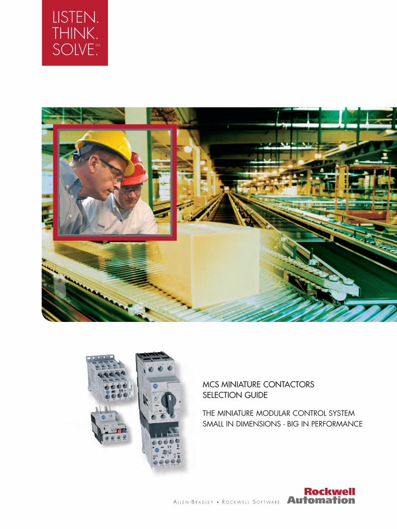
MCS MINIATURE CONTACTORS SELECTION GUIDE
THE MINIATURE MODULAR CONTROL SYSTEM SMALL IN DIMENSIONS - BIG IN PERFORMANCE

2
THE NEW MINIATURE CONTACTOR FROM ROCKWELL AUTOMATION:
• Switching and protection ofDOL or reversing motors up to5.5 kW at 400V and 690V.
• Switching of illumination orheating loads up to 20 A.
• Reliability for switching of signals down to 15V/2 mA.
ON-MACHINE CONTROLS INDUSTRIAL PRODUCTION
Overload Protection
DOL-Starter
Reversing Starter
Overload Protection
Short Circuit Protection
For Reversing Motors
Overload Protection
Short Circuit Protection
DOL-Starter SHORT CIRCUIT PROTECTION RELIABILITY
• The Bulletin 140-M motor protection circuit breaker is the ideal device for economic and compact starter solutionsproviding short circuit and motor overload protection.
• The excellent breaking capacity provideseffective, fast shut-off in case of short-circuits, limiting equipment damage.
• Sensitivity under phase loss conditionsthrough differential mechanism.
• Temperature compensated for precisemotor protection from -20°C to + 60°C.
• Only one DIN Rail required for the complete starter.
PROTECTION FOR AC AND DC MOTORS
• The Bulletin 193-K thermal overload relay is designed to work with Bulletin 100-K mini contactors.
• Sensitivity under phase loss conditions through differential mechanism.
• Temperature compensated for precise motor protection from -20°C to + 60°C.
REVERSING AND STAR-DELTA STARTERS
• With the Bulletin 100-K mini contactor and the Bulletin 140-M circuit breaker, it’s easier than ever to assemble reversing and star-delta starters.
• Connection kit for easy and time-saving wiring.
3
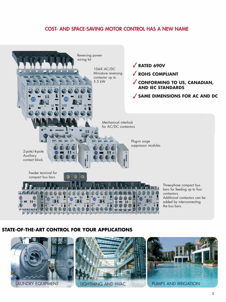
LAUNDRY EQUIPMENT LIGHTNING AND HVAC PUMPS AND IRRIGATION
STATE-OF-THE-ART CONTROL FOR YOUR APPLICATIONS
Reversing power wiring kit
Feeder terminal forcompact bus bars
Three-phase compact busbars for feeding up to fourcontactors. Additional contactors can beadded by interconnectingthe bus bars.
2-pole/4-poleAuxiliary contact block
104-K AC/DCMiniature reversingcontactor up to 5.5 kW
Plug-in surge suppressor modules
Mechanical interlockfor AC/DC contactors
COST- AND SPACE-SAVING MOTOR CONTROL HAS A NEW NAME
RATED 690V
ROHS COMPLIANT
CONFORMING TO US, CANADIAN, AND IEC STANDARDS
SAME DIMENSIONS FOR AC AND DC

4
ALL-AROUND SAFETY
• 100-K: Mechanically linked performance between main contacts andinternal auxiliary contacts. This feature provides status feedback in theevent of a contact weld.
• 100-K/100-KF: Mirror contact between main and auxiliary contacts asper IEC 60947-4-1 prevent any status condition if a N.O. power polewelds.
36 mm 9 mm
TIME-SAVINGFEATURES
PLUGGABLE SURGE SUPPRESSOR MODULES
• Suppressor modules are simplyplugged on the front of thecontactors, next to the auxiliarycontact blocks.
• No wiring required: fast and easy installation.
COMPACT AUXILIARY CONTACT BLOCKS
• The front pluggable auxiliary contactblocks are 36 mm wide, leaving spacefor a 9 mm wide surge suppressor module next to it.
• Large variety of contact configurations.
MIRROR AND MECHANICALLY LINKED DESIGN
Main Unit
Off
a a
AdderDeck
1
2 4
3 5
6 24 3222
21 23 31
A1
A2
HIGH FLEXIBILITY CONFIGURATIONFOR REVERSING CONTACTORS
• The front pluggable mechanical interlockfor AC and DC contactors allows topmounting of auxiliary contact blocks andsurge suppressor modules.
• High flexibility for easy tailoring to application needs.
• All front-mounted modules are pluggable.
• Sturdy, molded, reversing wiring kits makethe assembly fast and easy.
2a ≥ 0.5 mm 2a ≥ 0.5 mm
5
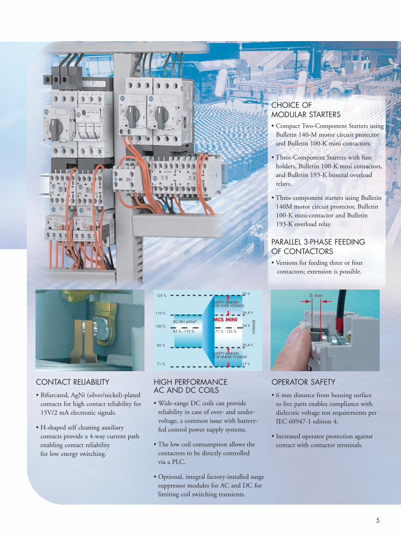
CHOICE OFMODULAR STARTERS• Compact Two-Component Starters using
Bulletin 140-M motor circuit protectorand Bulletin 100-K mini contactors.
• Three-Component Starters with fuse holders, Bulletin 100-K mini contactors,and Bulletin 193-K bimetal overloadrelays.
• Three-component starters using Bulletin140M motor circuit protector, Bulletin100-K mini-contactor and Bulletin 193-K overload relay.
PARALLEL 3-PHASE FEEDINGOF CONTACTORS• Versions for feeding three or four
contactors; extension is possible.
HIGH PERFORMANCEAC AND DC COILS
• Wide-range DC coils can provide reliability in case of over- and under-voltage, a common issue with battery-fed control power supply systems.
• The low coil consumption allows thecontactors to be directly controlled via a PLC.
• Optional, integral factory-installed surgesuppressor modules for AC and DC forlimiting coil switching transients.
OPERATOR SAFETY
• 6 mm distance from housing surface to live parts enables compliance with dielectric voltage test requirements perIEC 60947-1 edition 4.
• Increased operator protection againstcontact with contactor terminals.
CONTACT RELIABILITY
• Bifurcated, AgNi (silver/nickel)-platedcontacts for high contact reliability for15V/2 mA electronic signals.
• H-shaped self cleaning auxiliary contacts provide a 4-way current pathenabling contact reliability for low energy switching.
30 V
24 V
17 V71 %
85 %
100 %IEC/EN 60947:
85 % - 110 %
110 %
125 %
SAFETY MARGIN FOR OVER VOLTAGE
SAFETY MARGIN FOR UNDER VOLTAGE
MCS MINI
20,4 V
VOLT
AG
E
71 % - 125 %
26,4 V
6 mm

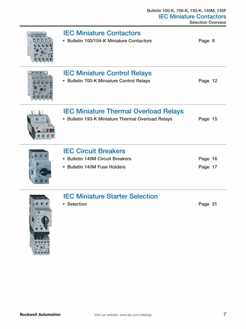
Bulletin 100-K, 700-K, 193-K, 140M, 140F
IEC Miniature Contactors
7Visit our website: www.ab.com/catalogsRockwell Automation
Selection Overview
IEC Miniature Contactors• Bulletin 100/104-K Miniature Contactors Page 8
IEC Miniature Control Relays• Bulletin 700-K Miniature Control Relays Page 12
IEC Miniature Thermal Overload Relays• Bulletin 193-K Miniature Thermal Overload Relays Page 15
IEC Circuit Breakers• Bulletin 140M Circuit Breakers Page 16
• Bulletin 140M Fuse Holders Page 17
IEC Miniature Starter Selection• Selection Page 21
Bulletin 100/104-K
IEC Miniature Contactors
8 Visit our website: www.ab.com/catalogs Rockwell Automation
Standards Compliance
Approvals
Overview/Product Selection
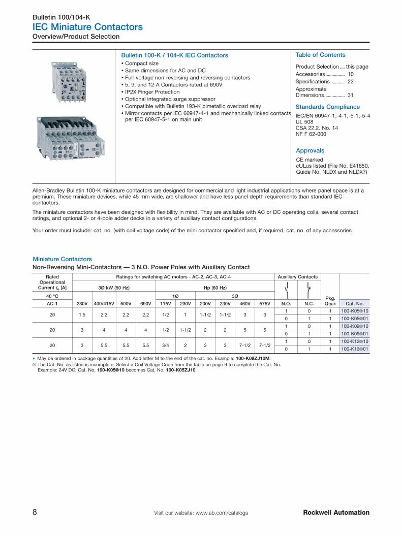
Bulletin 100-K / 104-K IEC Contactors
The miniature contactors have been designed with flexibility in mind. They are available with AC or DC operating coils, several contactratings, and optional 2- or 4-pole adder decks in a variety of auxiliary contact configurations.
Your order must include: cat. no. (with coil voltage code) of the mini contactor specified and, if required, cat. no. of any accessories
Miniature Contactors
CE markedcULus listed (File No. E41850,Guide No. NLDX and NLDX7)
Non-Reversing Mini-Contactors — 3 N.O. Power Poles with Auxiliary Contact
Table of Contents
Product Selection .... this pageAccessories................ 10Specifications............ 22ApproximateDimensions................. 31
Allen-Bradley Bulletin 100-K miniature contactors are designed for commercial and light industrial applications where panel space is at apremium. These miniature devices, while 45 mm wide, are shallower and have less panel depth requirements than standard IECcontactors.
� Compact size� Same dimensions for AC and DC� Full-voltage non-reversing and reversing contactors� 5, 9, and 12 A Contactors rated at 690V� IP2X Finger Protection� Optional integrated surge suppressor� Compatible with Bulletin 193-K bimetallic overload relay� Mirror contacts per IEC 60947-4-1 and mechanically linked contacts
per IEC 60947-5-1 on main unitIEC/EN 60947-1,-4-1,-5-1,-5-4UL 508CSA 22.2. No. 14NF F 62-000
RatedOperational
Current Ie [A]
Ratings for switching AC motors - AC-2, AC-3, AC-4 Auxiliary Contacts
Pkg.Qty.�
3Ø kW (50 Hz) Hp (60 Hz)
40 °C
230V 400/415V 500V 690V
1Ø 3Ø
AC-1 115V 230V 200V 230V 460V 575V N.O. N.C. Cat. No.
20 1.5 2.2 2.2 2.2 1/2 1 1-1/2 1-1/2 3 31 0 1 100-K05⊗10
0 1 1 100-K05⊗01
20 3 4 4 4 1/2 1-1/2 2 2 5 51 0 1 100-K09⊗10
0 1 1 100-K09⊗01
20 3 5.5 5.5 5.5 3/4 2 3 3 7-1/2 7-1/21 0 1 100-K12⊗10
0 1 1 100-K12⊗01
� May be ordered in package quantities of 20. Add letter M to the end of the cat. no. Example: 100-K09ZJ10M.⊗ The Cat. No. as listed is incomplete. Select a Coil Voltage Code from the table on page 9 to complete the Cat. No.
Example: 24V DC: Cat. No. 100-K05⊗⊗10 becomes Cat. No. 100-K05ZJ10.

Bulletin 100/104-K
IEC Miniature Contactors
9Visit our website: www.ab.com/catalogsRockwell Automation
Product Selection
Non-Reversing Mini-Contactors — 4 Power Poles
Reversing Mini-Contactors — 3 N.O. Power Poles with Auxiliary Contact
⊗ Coil Voltage CodeThe Cat. No. as listed is incomplete. Select a coil voltage code from the table below to complete the Cat. No. Example: 120V, 60 Hz:Cat. No. 100-K09⊗10 becomes Cat. No.100-K09D10.
AC Voltages [V] 24 110 120 230 240 400 480 600
50 Hz — D — — — — — —
60 Hz — — D — — — B VC
50/60 Hz KJ — — KF KA KN — —
DC Voltages [V] 12 24 110 125 220 250
Standard ZQ ZJ ZD ZS ZA ZT
with Integrated Diode — DJ — — — —
For other voltages, see table on page 31
RatedOperational
Current Ie [A]
Ratings for switching AC motors - AC-2, AC-3Contact Configuration,
Main Pole
Pkg.Qty.�
3Ø kW (50 Hz) Hp (60 Hz)
40 °C
230V 400/415V 500V 690V
1Ø 3Ø
AC-1 115V 230V 200V 230V 460V 575V N.O. N.C. Cat. No.
20 1.5 2.2 2.2 2.2 1/2 1 1-1/2 1-1/2 3 3
4 0 1 100-K05⊗400
3 1 1 100-K05⊗300
2 2 1 100-K05⊗200
20 3 4 4 4 1/2 1-1/2 2 2 5 5
4 0 1 100-K09⊗400
3 1 1 100-K09⊗300
2 2 1 100-K09⊗200
20 3 5.5 5.5 5.5 3/4 2 3 3 7-1/2 7-1/2
4 0 1 100-K12⊗400
3 1 1 100-K12⊗300
2 2 1 100-K12⊗200
� May be ordered in package quantities of 20. Add letter M to the end of the cat. no. Example: 100-K09ZJ400M.⊗ The Cat. No. as listed is incomplete. Select a Coil Voltage Code from the table below to complete the Cat. No.
Example: 24V DC: Cat. No. 100-K05⊗⊗400 becomes Cat. No. 100-K05ZJ400.
RatedOperational
Current Ie [A]
Ratings for switching AC motors - AC-2, AC-3, AC-4Auxiliary Contacts
per Contactor�
3Ø kW (50 Hz) Hp (60 Hz)
40 °C
230V 400/415V 500V 690V
1Ø 3Ø
AC-1 115V 230V 200V 230V 460V 575V N.O. N.C. Cat. No.
20 1.5 2.2 2.2 2.2 — — 1-1/2 1-1/2 3 3 0 1 104-K05⊗02
20 3 4 4 4 — — 2 2 5 5 0 1 104-K09⊗02
20 3 5.5 5.5 5.5 — — 3 3 7-1/2 7-1/2 0 1 104-K12⊗02
� Used for electrical interlocking⊗ The Cat. No. as listed is incomplete. Select a standard Coil Voltage Code from the table below to complete the Cat. No.
Example: 230V, 50/60 Hz: Cat. No. 104-K05⊗⊗02 becomes Cat. No. 104-K05KF02.Bulletin 104-K reversing contactors are factory assembled and include contactors, mechanical interlock (Cat. No. 100-KMCH) and wiring kit (Cat. No. 100-KPR) for power and control circuit (electrical interlock).
Bulletin 100-K, 700-K, 193-K, 140M, 140F
IEC Miniature Contactors
10 Visit our website: www.ab.com/catalogs Rockwell Automation
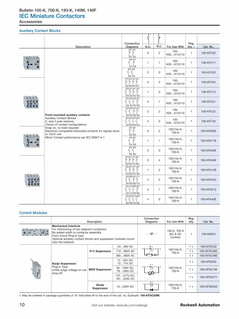
Accessories
Auxiliary Contact Blocks
Control Modules
DescriptionConnectionDiagrams For Use With
Pkg.Qty. �N.O. N.C. Cat. No.
Front-mounted auxiliary contactsAuxiliary Contact Blocks 2- and 4-pole versionsChoice of contact configurationsSnap on, no tools requiredElectronic-compatible bifurcated contacts for signals downto 15V/2 mAMirror Contact performance per IEC 60947-4-1
21 31
3222
0 2 100-K05…K12⊗10 1 100-KFC02
23 31
24 32
1 1 100-K05…K12⊗10 1 100-KFC11
23 33
24 34
2 0 100-K05…K12⊗10 1 100-KFC20
41 51
5242
21 31
3222
0 4 100-K05…K12⊗10 1 100-KFC04
23 31 41
4224 32
51
52
1 3 100-K05…K12⊗10 1 100-KFC13
43 53 31
44 54 32
23
24
3 1 100-K05…K12⊗10 1 100-KFC31
23 53 31 41
4224 54 32
2 2 100-K05…K12⊗10 1 100-KFC22
23 33 43 53
5424 34 44
4 0 100-K05…K12⊗10 1 100-KFC40
51 61
6252
0 2 100/104-K,700-K 1 100-KFA02E
53 61
54 62
1 1 100/104-K,700-K 1 100-KFA11E
53 63
54 64
2 0 100/104-K,700-K 1 100-KFA20E
71 81
8272
51 61
6252
0 4 100/104-K,700-K 1 100-KFA04E
53 61 71
7254 62
81
82
1 3 100/104-K,700-K 1 100-KFA13E
53 83 61 71
7254 84 62
2 2 100/104-K,700-K 1 100-KFA22Z
73 83 61
74 84 62
53
54
3 1 100/104-K,700-K 1 100-KFA31Z
53 63 73 83
8454 64 74
4 0 100/104-K,700-K 1 100-KFA40E
DescriptionConnection Diagrams For Use With
Pkg.Qty. Cat. No.
Mechanical InterlockFor interlocking of two adjacent contactorsNo added width to contactor assemblyFront mount Plug-In typeOptional auxiliary contact blocks and suppressor modules mountonto the interlock
100-K, 700-K(AC & DCControl)
1 100-KMCH
Surge SuppressorPlug-in TypeLimits surge voltage on coildrop-off
R-C Suppressor
24…48V AC100/104-K,
700-K
1 � 100-KFSC50
110…280V AC 1 � 100-KFSC280
380…480V AC 1 � 100-KFSC480
MOV Suppressor
12…55V AC,12…77V DC
100/104-K,700-K
1 � 100-KFSV55
56…136V AC,78…180V DC 1 � 100-KFSV136
137…277V AC,181…250V DC 1 � 100-KFSV277
DiodeSuppressor 12…250V DC 100/104-K,
700-K 1 � 100-KFSD250
� May be ordered in package quantities of 10. Add letter M to the end of the cat. no. Example: 100-KFSC50M.

Bulletin 100-K, 700-K, 193-K, 140M, 140F
IEC Miniature Contactors
11Visit our website: www.ab.com/catalogsRockwell Automation
Connecting Components
Accessories
Timers
Marking Systems
DescriptionPkg.Qty. Cat. No.
Label Sheet10 sheets with 105 self-adhesive paper labels each, 6 x 17 mm 10 100-FMS
Snap-In Hinged Marker Card 5 1492-MH6X12
DescriptionConnection Diagrams For Use With
Pkg.Qty. Cat. No.
Solid-State Timing Element110…250V AC or DC
On-Delay,0.1…3 s
S1
NK1
1
2
O / I
~
100/104-K, 700-K 10
100-KT3S
On-Delay,1…30 s 100-KT30S
Star-Delta Timer
After the set timehas elapsed, the
K3 contactor (Y) isde-energized andthen after a time
of 90 ± 30 ms theK2 Contactor
(Delta) isenergized.
110…120V 50/60Hz
100/104-K, 700-K 10
100-KTSDA1
220…250V 50/60Hz
100-KTSDA2
48V AC 50/60 Hz 100-KTSDA3
35 mm DIN Rail Mounting AdapterFor easy mounting of timer modules on standard DIN Rail 100-KT 10 100-KTM
Description For Use WithPkg.Qty. Cat. No.
ECO Connecting ModuleFor DOL and reversing startersProvides electrical and mechanical link
Connects:140M-C circuit breakers with 100-K
contactors140M-C to 100-K 1 � 140M-C-PEK12
Power Wiring KitFor Reversing and Star/Delta
combinations. Star-point bridge notincluded.
100-K 1 100-KPR
Feeder Terminal for Compact BusBars Supply of compact bus bars 100-K 1 100-KWT
Three-Phase Compact Bus Bars
For 100-K, 5…12 A contactors45 mm spacing (3 connections)� 100-K 1 100-KW453
For 100-K, 5…12 A contactors45 mm spacing (4 connections)� 100-K 1 100-KW454
� May be ordered in package quantities of 10. Add letter M to the end of the cat. no. Example: 140M-C-PEK12M.�Combinations possible. Example: For 6 contactor connections use one cat. no. 100-KW453 and one cat. no. 100-KW454.
Bulletin 700-K
IEC Miniature Control Relays
12 Visit our website: www.ab.com/catalogs Rockwell Automation
Standards Compliance
Approvals
Overview/Product Selection
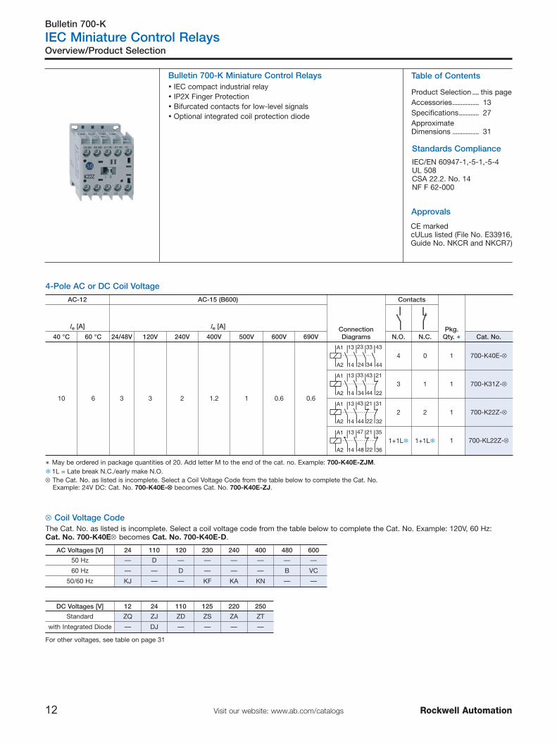
Bulletin 700-K Miniature Control Relays
CE markedcULus listed (File No. E33916,Guide No. NKCR and NKCR7)
4-Pole AC or DC Coil Voltage
⊗ Coil Voltage CodeThe Cat. No. as listed is incomplete. Select a coil voltage code from the table below to complete the Cat. No. Example: 120V, 60 Hz:Cat. No. 700-K40E⊗ becomes Cat. No. 700-K40E-D.
AC Voltages [V] 24 110 120 230 240 400 480 600
50 Hz — D — — — — — —
60 Hz — — D — — — B VC
50/60 Hz KJ — — KF KA KN — —
DC Voltages [V] 12 24 110 125 220 250
Standard ZQ ZJ ZD ZS ZA ZT
with Integrated Diode — DJ — — — —
For other voltages, see table on page 31
Table of Contents
Product Selection .... this pageAccessories................ 13Specifications............ 27ApproximateDimensions ................ 31
� IEC compact industrial relay� IP2X Finger Protection� Bifurcated contacts for low-level signals� Optional integrated coil protection diode
IEC/EN 60947-1,-5-1,-5-4UL 508CSA 22.2. No. 14NF F 62-000
AC-12 AC-15 (B600)
ConnectionDiagrams
Contacts
Pkg.Qty. �
Ie [A] Ie [A]
40 °C 60 °C 24/48V 120V 240V 400V 500V 600V 690V N.O. N.C. Cat. No.
10 6 3 3 2 1.2 1 0.6 0.6
A1 13 23 33 43
44A2 14 24 34
4 0 1 700-K40E-⊗
A1 13 33 43 21
22A2 14 34 44
3 1 1 700-K31Z-⊗
A1 13 43 21 31
32A2 14 44 22
2 2 1 700-K22Z-⊗
A1 13 47 21 35
36A2 14 48 22
1+1L� 1+1L� 1 700-KL22Z-⊗
� May be ordered in package quantities of 20. Add letter M to the end of the cat. no. Example: 700-K40E-ZJM.� 1L = Late break N.C./early make N.O.⊗ The Cat. No. as listed is incomplete. Select a Coil Voltage Code from the table below to complete the Cat. No.
Example: 24V DC: Cat. No. 700-K40E-⊗⊗ becomes Cat. No. 700-K40E-ZJ.

Bulletin 700-K
IEC Miniature Control Relays
13Visit our website: www.ab.com/catalogsRockwell Automation
Auxiliary Contact Blocks
Accessories
Control Modules
DescriptionConnectionDiagrams For Use With
Pkg.Qty. �N.O. N.C. Cat. No.
Front-mounted auxiliary contactsAuxiliary Contact Blocks 2- and 4-pole versionsChoice of contact configurationsSnap on, no tools requiredElectronic-compatible bifurcated contacts for signalsdown to 15V/2 mA
51 61
6252
0 2 100/104-K,700-K 1 100-KFA02E
53 61
54 62
1 1 100/104-K,700-K 1 100-KFA11E
53 63
54 64
2 0 100/104-K,700-K 1 100-KFA20E
71 81
8272
51 61
6252
0 4 100/104-K,700-K 1 100-KFA04E
53 61 71
7254 62
81
82
1 3 100/104-K,700-K 1 100-KFA13E
53 83 61 71
7254 84 62
2 2 100/104-K,700-K 1 100-KFA22Z
73 83 61
74 84 62
53
54
3 1 100/104-K,700-K 1 100-KFA31Z
53 63 73 83
8454 64 74
4 0 100/104-K,700-K 1 100-KFA40E
� May be ordered in package quantities of 10. Add letter M to the end of the cat. no. Example: 100-KFA02EM.
DescriptionConnection Diagrams For Use With
Pkg.Qty. Cat. No.
Mechanical InterlockFor interlocking of two adjacent contactorsNo added width to contactor assemblyFront mount Plug-In typeOptional auxiliary contact blocks and suppressor modules mountonto the interlock
100-K, 700-K(AC & DCControl)
1 100-KMCH
Surge SuppressorPlug-in TypeLimits surge voltage on coildrop-off
R-C Suppressor
24…48V AC100/104-K,
700-K
1 � 100-KFSC50
110…280V AC 1 � 100-KFSC280
380…480V AC 1 � 100-KFSC480
MOV Suppressor
12…55V AC,12…77V DC
100/104-K,700-K
1 � 100-KFSV55
56…136V AC,78…180V DC 1 � 100-KFSV136
137…277V AC,181…250V DC 1 � 100-KFSV277
Diode Suppressor 12…250V DC 100/104-K,700-K 1 � 100-KFSD250
� May be ordered in package quantities of 10. Add letter M to the end of the cat. no. Example: 100-KFSC50M.
Bulletin 700-K
IEC Miniature Control Relays
14 Visit our website: www.ab.com/catalogs Rockwell Automation
Accessories
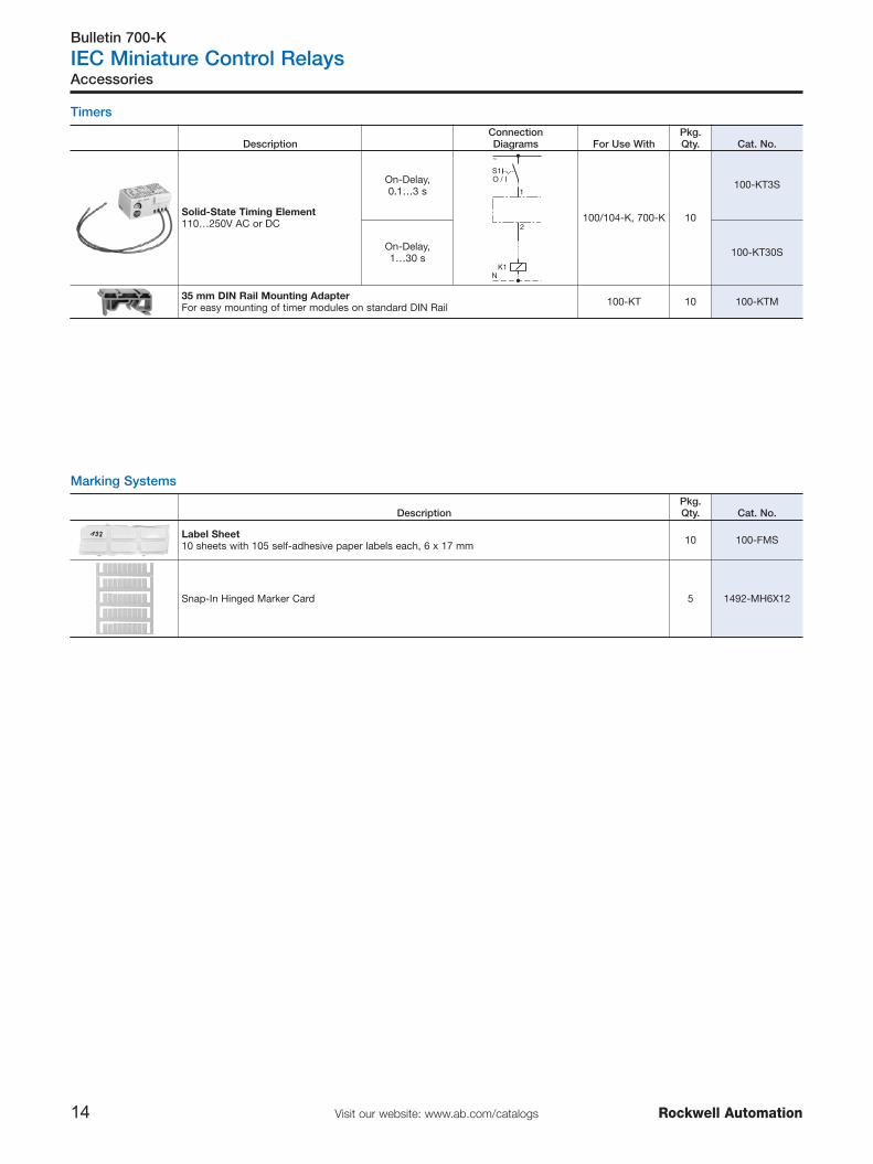
Timers
Marking Systems
DescriptionPkg.Qty. Cat. No.
Label Sheet10 sheets with 105 self-adhesive paper labels each, 6 x 17 mm 10 100-FMS
Snap-In Hinged Marker Card 5 1492-MH6X12
DescriptionConnection Diagrams For Use With
Pkg.Qty. Cat. No.
Solid-State Timing Element110…250V AC or DC
On-Delay,0.1…3 s
S1
NK1
1
2
O / I
~
100/104-K, 700-K 10
100-KT3S
On-Delay,1…30 s 100-KT30S
35 mm DIN Rail Mounting AdapterFor easy mounting of timer modules on standard DIN Rail 100-KT 10 100-KTM
Bulletin 193-K
IEC Miniature Thermal Overload Relays
15Visit our website: www.ab.com/catalogsRockwell Automation
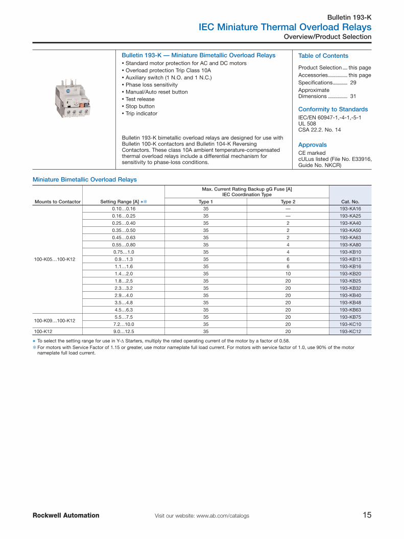
Bulletin 193-K — Miniature Bimetallic Overload Relays
Bulletin 193-K bimetallic overload relays are designed for use withBulletin 100-K contactors and Bulletin 104-K ReversingContactors. These class 10A ambient temperature-compensatedthermal overload relays include a differential mechanism forsensitivity to phase-loss conditions.
Conformity to Standards
Approvals
Miniature Bimetallic Overload Relays
Overview/Product Selection
Table of Contents
Product Selection .... this pageAccessories................ this pageSpecifications............ 29ApproximateDimensions ................ 31
� Standard motor protection for AC and DC motors� Overload protection Trip Class 10A� Auxiliary switch (1 N.O. and 1 N.C.)� Phase loss sensitivity� Manual/Auto reset button� Test release� Stop button� Trip indicator
CE markedcULus listed (File No. E33916,Guide No. NKCR)
Mounts to Contactor Setting Range [A] ��
Max. Current Rating Backup gG Fuse [A]IEC Coordination Type
Cat. No.Type 1 Type 2
100-K05…100-K12
0.10…0.16 35 — 193-KA16
0.16…0.25 35 — 193-KA25
0.25…0.40 35 2 193-KA40
0.35…0.50 35 2 193-KA50
0.45…0.63 35 2 193-KA63
0.55…0.80 35 4 193-KA80
0.75…1.0 35 4 193-KB10
0.9…1.3 35 6 193-KB13
1.1…1.6 35 6 193-KB16
1.4…2.0 35 10 193-KB20
1.8…2.5 35 20 193-KB25
2.3…3.2 35 20 193-KB32
2.9…4.0 35 20 193-KB40
3.5…4.8 35 20 193-KB48
4.5…6.3 35 20 193-KB63
100-K09…100-K125.5…7.5 35 20 193-KB75
7.2…10.0 35 20 193-KC10
100-K12 9.0…12.5 35 20 193-KC12
� To select the setting range for use in Y-Δ Starters, multiply the rated operating current of the motor by a factor of 0.58.� For motors with Service Factor of 1.15 or greater, use motor nameplate full load current. For motors with service factor of 1.0, use 90% of the motor
nameplate full load current.
IEC/EN 60947-1,-4-1,-5-1UL 508CSA 22.2. No. 14

Bulletin 140M
IEC Circuit Breakers
16 Visit our website: www.ab.com/catalogs Rockwell Automation
Bulletin 140M Motor Protection Circuit Breakers
Conformity to Standards
Approvals
Product Selection — Motor Protection Circuit Breakers
Overview/Product Selection
� Short-circuit protection — standard magnetic trip (fixed at 13 x Ie)� Motor overload protection — Trip Class 10
CE markedcULus listed (File No.E54612, Guide No. NLRV andNLRV7)
Table of Contents
Product Selection.... this pageAccessories ............... 18
RatedOperationalCurrent (Ie)
MotorCurrent
AdjustmentRange
MagneticTrip
Current[A]
UltimateInterruptingCurrent [kA]
(Icu) Max. kW, 3-Phase 3-phase Hp Ratings [Hp]�
Cat. No.[A] [A] 400V 480V 230V 400/415V 500V 690V 200V 230V 460V 575V
C-Frame
0.16 A 0.10…0.16 2.1 100 65 — 0.02 — — — — — — 140M-C2E-A16
0.25 A 0.16…0.25 3.3 100 65 — 0.06 — — — — — — 140M-C2E-A25
0.40 A 0.25…0.40 5.2 100 65 — 0.09 — — — — — — 140M-C2E-A40
0.63 A 0.40…0.63 8.2 100 65 0.06...0.09 0.12...0.18 0.18 0.25 — — — — 140M-C2E-A63
1.0 A 0.63…1.0 13 100 65 0.12 0.25 0.25...0.37 0.37...0.55 — — — 0.5 140M-C2E-B10
1.6 A 1.0…1.6 21 100 65 0.18...0.25 0.37...0.55 0.55...0.75 0.75...1.1 — — 0.5...0.75 0.75 140M-C2E-B16
2.5 A 1.6…2.5 33 100 65 0.37 0.75 1.1 1.8 0.5 0.5 0.75...1 1...1.5 140M-C2E-B25
4.0 A 2.5…4.0 52 100 65 0.55...0.75 1.1...1.5 1.5...2.2 2.2...3.0 0.75 0.75 1.5...2 2...3 140M-C2E-B40
6.3 A 4.0…6.3 82 100 65 1.1...1.5 2.2 2.5...3.0 4.0 1 1...1.5 3 5 140M-C2E-B63
10 A 6.3…10 130 100 65 2.2 3.0...4.0 4.0...6.3 5.5...7.5 1.5...2 2...3 5 7.5 140M-C2E-C10
16 A 10…16 208 50 30 3.0...4.0 5.5...7.5 7.5...10 11...13 3 — 7.5...10 10 140M-C2E-C16
20 A 14.5…20 260 15 30 4.0...5.5 7.5...10 11 15...17 5 5 — 15 140M-C2E-C20
25 A 18…25 325 15 25 — 11 15 18.5...22 — 7.5 15 20 140M-C2E-C25
� Horsepower/kW ratings shown in the table above are for reference. The final selection of the MPCB depends on the actual motor full load current andservice factor.
IEC/EN 60947-1,-2,-4-1,-5-1UL 508CSA 22.2. No. 14NF F 62-000
� Current Range 0.1…25 A� UL Listed for motor loads
− Short-circuit protection− Overload protection
� Visible trip indication− Additional short-circuit trip identification
� High current limiting� High switching capacity
Bulletin 140M Motor Protection Circuit Breakers provide short-circuit and overload protection for individual motor loads. Field-installed accessories make installation and wiring easy.
Bulletin 140M, 140F
IEC Circuit Breakers
17Visit our website: www.ab.com/catalogsRockwell Automation
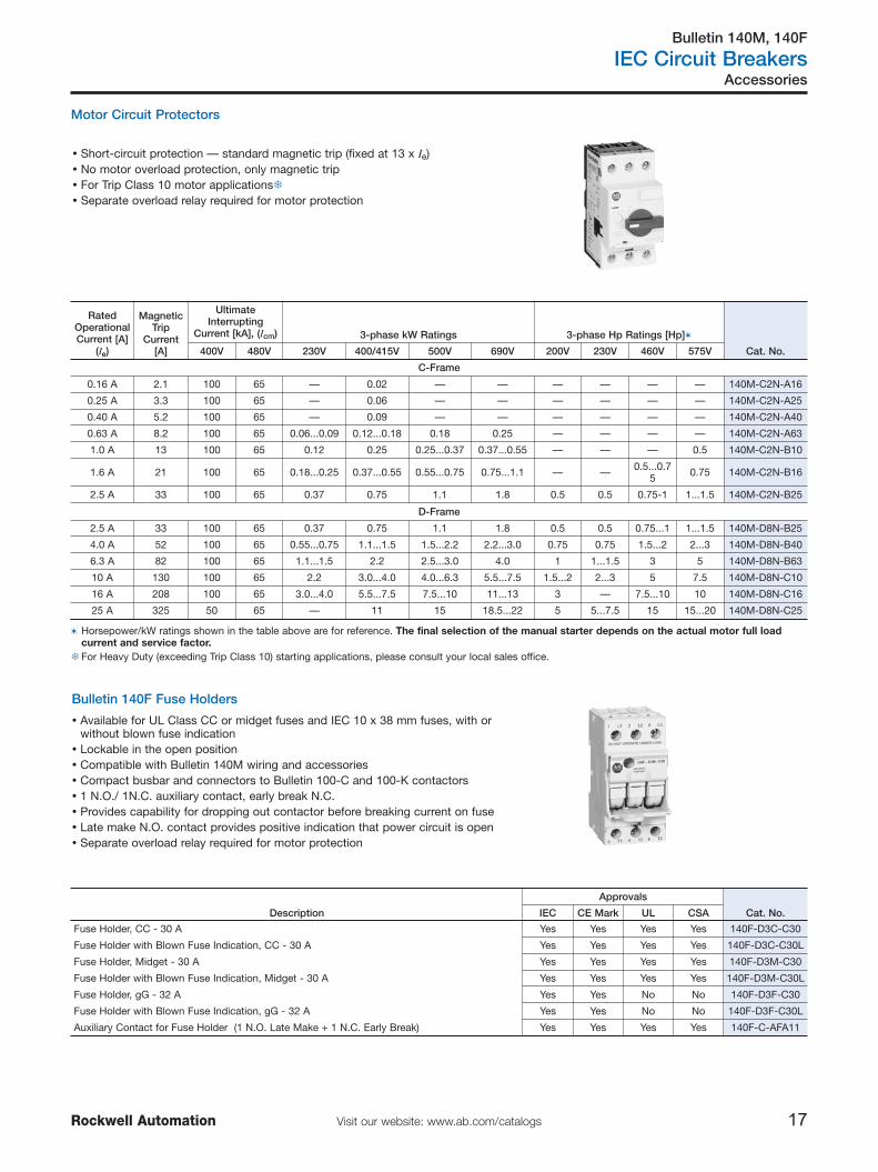
Motor Circuit Protectors
Accessories
Bulletin 140F Fuse Holders
Description
Approvals
Cat. No.IEC CE Mark UL CSA
Fuse Holder, CC - 30 A Yes Yes Yes Yes 140F-D3C-C30
Fuse Holder with Blown Fuse Indication, CC - 30 A Yes Yes Yes Yes 140F-D3C-C30L
Fuse Holder, Midget - 30 A Yes Yes Yes Yes 140F-D3M-C30
Fuse Holder with Blown Fuse Indication, Midget - 30 A Yes Yes Yes Yes 140F-D3M-C30L
Fuse Holder, gG - 32 A Yes Yes No No 140F-D3F-C30
Fuse Holder with Blown Fuse Indication, gG - 32 A Yes Yes No No 140F-D3F-C30L
Auxiliary Contact for Fuse Holder (1 N.O. Late Make + 1 N.C. Early Break) Yes Yes Yes Yes 140F-C-AFA11
� Short-circuit protection — standard magnetic trip (fixed at 13 x Ie)� No motor overload protection, only magnetic trip� For Trip Class 10 motor applications�� Separate overload relay required for motor protection
� Available for UL Class CC or midget fuses and IEC 10 x 38 mm fuses, with orwithout blown fuse indication
� Lockable in the open position� Compatible with Bulletin 140M wiring and accessories� Compact busbar and connectors to Bulletin 100-C and 100-K contactors � 1 N.O./ 1N.C. auxiliary contact, early break N.C.� Provides capability for dropping out contactor before breaking current on fuse� Late make N.O. contact provides positive indication that power circuit is open� Separate overload relay required for motor protection
RatedOperationalCurrent [A]
(Ie)
MagneticTrip
Current[A]
UltimateInterrupting
Current [kA], (Icm) 3-phase kW Ratings 3-phase Hp Ratings [Hp]�
Cat. No.400V 480V 230V 400/415V 500V 690V 200V 230V 460V 575V
C-Frame
0.16 A 2.1 100 65 — 0.02 — — — — — — 140M-C2N-A16
0.25 A 3.3 100 65 — 0.06 — — — — — — 140M-C2N-A25
0.40 A 5.2 100 65 — 0.09 — — — — — — 140M-C2N-A40
0.63 A 8.2 100 65 0.06...0.09 0.12...0.18 0.18 0.25 — — — — 140M-C2N-A63
1.0 A 13 100 65 0.12 0.25 0.25...0.37 0.37...0.55 — — — 0.5 140M-C2N-B10
1.6 A 21 100 65 0.18...0.25 0.37...0.55 0.55...0.75 0.75...1.1 — — 0.5...0.75 0.75 140M-C2N-B16
2.5 A 33 100 65 0.37 0.75 1.1 1.8 0.5 0.5 0.75-1 1...1.5 140M-C2N-B25
D-Frame
2.5 A 33 100 65 0.37 0.75 1.1 1.8 0.5 0.5 0.75...1 1...1.5 140M-D8N-B25
4.0 A 52 100 65 0.55...0.75 1.1...1.5 1.5...2.2 2.2...3.0 0.75 0.75 1.5...2 2...3 140M-D8N-B40
6.3 A 82 100 65 1.1...1.5 2.2 2.5...3.0 4.0 1 1...1.5 3 5 140M-D8N-B63
10 A 130 100 65 2.2 3.0...4.0 4.0...6.3 5.5...7.5 1.5...2 2...3 5 7.5 140M-D8N-C10
16 A 208 100 65 3.0...4.0 5.5...7.5 7.5...10 11...13 3 — 7.5...10 10 140M-D8N-C16
25 A 325 50 65 — 11 15 18.5...22 5 5...7.5 15 15...20 140M-D8N-C25
� Horsepower/kW ratings shown in the table above are for reference. The final selection of the manual starter depends on the actual motor full loadcurrent and service factor.
� For Heavy Duty (exceeding Trip Class 10) starting applications, please consult your local sales office.

Bulletin 140M
IEC Circuit Breakers
18 Visit our website: www.ab.com/catalogs Rockwell Automation
Accessories
Accessories
Description
Connection Diagram�
For UseWith Cat. No.
Operator Position �
Term.No. Description
OFF ON Tripped
Front-MountedAuxiliary Contact1-pole or 2-poleNo additional spacerequired- Only (1) per MPCB
O X O 13-14 N.O. Aux140M-C,
D, F 140M-C-AFA10
X O X 11-12 N.C. Aux 140M-C,D, F 140M-C-AFA01
O X O 13-14 N.O. Aux 13
14
21
22140M-C,
D, F 140M-C-AFA11
X O X 21-22 N.C. Aux
O X O 13-14 N.O. Aux
140M-C,D, F 140M-C-AFA20
O X O 23-24 N.O. Aux
X O X 11-12 N.C. Aux140M-C,
D, F 140M-C-AFA02
X O X 21-22 N.C. Aux
Right Side-MountedAuxiliary Contact2-poleAdds 9 mm to thewidth of the device- (2) per MPCB
O X O 33-34 N.O. Aux140M-C,
D, F 140M-C-ASA20
O X O 43-44 N.O. Aux
X O X 31-32 N.C. Aux31
32
41
42140M-C,
D, F 140M-C-ASA02
X O X 41-42 N.C. Aux
O X O 33-34 N.O. Aux140M-C,
D, F 140M-C-ASA11
X O X 41-42 N.C. Aux
� X = Contact Closed; O = Contact Open�

Bulletin 140M
IEC Circuit Breakers
19Visit our website: www.ab.com/catalogsRockwell Automation
Accessories
Accessories
Description
Connection Diagram�
For UseWith Cat. No.
Operator Position �
Term.No. Description
OFF ON Tripped
Front-Mounted TripContact2-poleIndicates tripping ofdeviceNo additional spacerequired
O X O 13-14 N.O. Aux140M-C,
D, F 140M-C-AFAR10A10
O O X 27-28N.O. Trip
(Short-Circuit& Overload)
X O X 11-12 N.C. Aux11
12
27
28
140M-C,D, F 140M-C-AFAR10A01
O O X 27-28N.O. Trip
(Short-Circuit& Overload)
Right-Side MountedTrip Contact2-poleIndicates tripping ofMotor ProtectionCircuit BreakerAdds 9 mm to thewidth of the circuitbreaker- Only (1) per MPCB- A Right-Sidemounted AuxiliaryContact may betandem mounted ontop of this TripContact
O O X 57-58N.O. Trip
(Short-Circuit& Overload) 57
58
67
68
I>>
140M-C,D, F 140M-C-ASAR10M10
O O X 67-68 N.O. Trip
O O X 57-58N.O. Trip
(Short-Circuit& Overload) 57
58
65
66
I>>
140M-C,D, F 140M-C-ASAR10M01
X X O 65-66 N.C. Trip
X X O 55-56N.C. Trip
(Short-Circuit& Overload) 140M-C,
D, F 140M-C-ASAR01M10
O O X 67-68 N.O. Trip
X X O 55-56N.C. Trip
(Short-Circuit& Overload) 140M-C,
D, F 140M-C-ASAR01M01
X X O 65-66 N.C. Trip
O O X 77-78 N.O. Trip(Short-Circuit) 140M-C,
D, F 140M-C-ASAM11
X X O 65-66 N.C. Trip(Short-Circuit)
� X = Contact Closed; O = Contact Open�
Bulletin 140M
IEC Circuit Breakers
20 Visit our website: www.ab.com/catalogs Rockwell Automation
Accessories
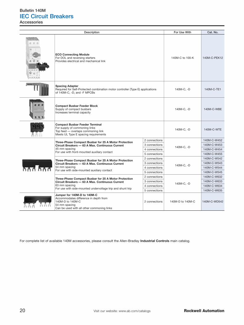
For complete list of available 140M accessories, please consult the Allen-Bradlay Industrial Controls main catalog.
Description For Use With Cat. No.
ECO Connecting ModuleFor DOL and reversing startersProvides electrical and mechanical link
140M-C to 100-K 140M-C-PEK12
Spacing AdapterRequired for Self-Protected combination motor controller (Type E) applicationsof 140M-C, -D, and -F MPCBs
140M-C, -D 140M-C-TE1
Compact Busbar Feeder BlockSupply of compact busbarsIncreases terminal capacity
140M-C, -D 140M-C-WBE
Compact Busbar Feeder TerminalFor supply of commoning linksTop feed — overlaps commoning linkMeets UL Type E spacing requirements
140M-C, -D 140M-C-WTE
Three-Phase Compact Busbar for 25 A Motor ProtectionCircuit Breakers — 63 A Max. Continuous Current45 mm spacingFor use with front-mounted auxiliary contact
2 connections
140M-C, -D
140M-C-W452
3 connections 140M-C-W453
4 connections 140M-C-W454
5 connections 140M-C-W455
Three-Phase Compact Busbar for 25 A Motor ProtectionCircuit Breakers — 63 A Max. Continuous Current54 mm spacingFor use with side-mounted auxiliary contact
2 connections
140M-C, -D
140M-C-W542
3 connections 140M-C-W543
4 connections 140M-C-W544
5 connections 140M-C-W545
Three-Phase Compact Busbar for 25 A Motor ProtectionCircuit Breakers — 63 A Max. Continuous Current63 mm spacingFor use with side-mounted undervoltage trip and shunt trip
2 connections
140M-C, -D
140M-C-W632
3 connections 140M-C-W633
4 connections 140M-C-W634
5 connections 140M-C-W635
Jumper for 140M-D to 140M-CAccommodates difference in depth from140M-D to 140M-C54 mm spacingCan be used with all other commoning links
2 connections 140M-D to 140M-C 140M-C-WD542

Bulletin 100-K/140M
IEC Miniature Starter Selection
21Visit our website: www.ab.com/catalogsRockwell Automation
Overview/Product Selection
Mini Starters
Table of Contents
Product Selection .... this page
+
+
� Power Range 0.1...12 A� Modular Eco Starter using Bulletin 140M Motor Protection Circuit
Breaker and Bulletin 100-K Mini Contactors� Mounting Options:
Snap Fixing on (1) 35 mm DIN Rail
Modular Eco Starter Component Selection
Use the chart to select components based on motor application data.
⊗ Coil Voltage CodeThe Cat. No. as listed is incomplete. Select a coil voltage code from the table below to complete the Cat. No. Example: 120V, 60 Hz:Cat. No. 100-K09⊗10 becomes Cat. No.100-K09D10.
AC Voltages [V] 24 110 120 230 240 400 480 600
50 Hz — D — — — — — —
60 Hz — — D — — — B VC
50/60 Hz KJ — — KF KA KN — —
DC Voltages [V] 12 24 110 125 220 250
Standard ZQ ZJ ZD ZS ZA ZT
with Integrated Diode — DJ — — — —
For other voltages, see table on page 31
MotorCurrent
AdjustmentRange
[A]
Type 1 Coordination DOL- and Reversing-Starters �
Max. Hp (60 Hz) Max. kW (50 Hz) ContactorEco Starter
Module Circuit Breaker
200V 230V 460V 575V 230V 400V 500V 690V
C-Frame and 100-K Mini Contactors
0.1…0.16 ⎯ ⎯ ⎯ ⎯ ⎯ 0.02 ⎯ ⎯ 100-K05⊗.. 140M-C-PEK12 140M-C2E-A16
0.16…0.25 ⎯ ⎯ ⎯ ⎯ 0.02 0.06 0.06 ⎯ 100-K05⊗.. 140M-C-PEK12 140M-C2E-A25
0.25…0.4 ⎯ ⎯ ⎯ ⎯ 0.06 0.09 0.12 ⎯ 100-K05⊗.. 140M-C-PEK12 140M-C2E-A40
0.4…0.63 ⎯ ⎯ ⎯ ⎯ 0.09 0.18 0.18 ⎯ 100-K05⊗.. 140M-C-PEK12 140M-C2E-A63
0.63…1.0 ⎯ ⎯ ⎯ 1/2 0.12 0.25 0.37 0.25 100-K05⊗.. 140M-C-PEK12 140M-C2E-B10
1.0…1.6 ⎯ ⎯ 0.5…0.75 3/4 0.25 0.55 0.75 0.37…0.55 100-K05⊗.. 140M-C-PEK12 140M-C2E-B16
1.6…2.5 1/2 1/2 0.75…1 1…1.5 0.55 0.75 1.1 0.75…1.1 100-K05⊗.. 140M-C-PEK12 140M-C2E-B25
2.5…4.0 3/4 3/4 1.5…2 2…3 0.75 1.5 1.8 1.8 100-K05⊗.. 140M-C-PEK12 140M-C2E-B40
4.0…6.3 1 1…1.5 3 5 1.5 2.2 2.2 4 100-K09⊗.. 140M-C-PEK12 140M-C2E-B63
6.3…10 1.6…2 2 5 7.5 2.2 4 4 ⎯ 100-K12⊗.. 140M-C-PEK12 140M-C2E-C10
10…16 3 ⎯ 7 1/2 ⎯ 4 5.5 ⎯ — 100-K12⊗.. 140M-C-PEK12 140M-C2E-C16
� Reversing Starters using 2 contactors 100-K..⊗01 and power wiring kit 100-KPR and if needed mechanical interlock 100-KMCH in addition.Horsepower and Kilowatt ratings shown in the table are for reference. Final selection of the starter depends upon the actual motor full-load current andservice factor.

Bulletin 100-K
IEC Miniature Contactors
22 Visit our website: www.ab.com/catalogs Rockwell Automation
IEC Specifications
Specifications
100/104-K
05 09 12
AC-1 Active Power Load (50 Hz);Ambient temperature 40°C
Ie ≤ 690V [A] 20 20 20
230V [kW] 8 8 8
240V [kW] 8.3 8.3 8.3
400V [kW] 14 14 14
415V [kW] 14 14 14
500V [kW] 17 17 17
690V [kW] 24 24 24
Ambient temperature 60°C
Ie ≤ 690V [A] 16 16 16
230V [kW] 6.4 6.4 6.4
240V [kW] 6.7 6.7 6.7
400V [kW] 11 11 11
415V [kW] 12 12 12
500V [kW] 14 14 14
690V [kW] 19 19 19
Switching of 3-phase Motors; (50 Hz)Ambient temperature 60°C, AC-2, AC-3, AC-4
230V [A] 6.3 11.3 11.3
240V [A] 6.3 11.3 11.3
400V [A] 4.9 8.5 11.5
415V [A] 4.9 8.5 11.5
500V [A] 3.9 6.8 9.2
690V [A] 2.8 4.9 6.7
230V [kW] 1.5 3 3
240V [kW] 1.5 3 3
400V [kW] 2.2 4 5.5
415V [kW] 2.2 4 5.5
500V [kW] 2.2 4 5.5
690V [kW] 2.2 4 5.5
AC-4 at approximately 200,000 operations
230V [A] 2.3 3.9 3.9
240V [A] 2.3 3.9 3.9
400V [A] 2 3.6 3.6
415V [A] 2 3.6 3.6
500V [A] 1.9 3.2 3.2
690V [A] — — —
230V [kW] 0.37 0.75 0.75
240V [kW] 0.37 0.75 0.75
400V [kW] 0.75 1.5 1.5
415V [kW] 0.75 1.5 1.5
500V [kW] 0.75 1.5 1.5
690V [kW] — — —
Max. switchingfrequency Ops/h 250 250 250
100/104-K
05 09 12
Star-Delta Starting (50 Hz)
≤ 230V [A] 11.3 20 20
≤ 240V [A] 11.3 20 20
400V [A] 8.5 15.5 15.5
415V [A] 8.5 15.5 15.5
500V [A] 6.8 12.4 12.4
690V [A] 4.9 8.9 8.9
230V [kW] 3 5.5 5.5
240V [kW] 3 5.5 5.5
400V [kW] 4 7.5 7.5
415V [kW] 4 7.5 7.5
500V [kW] 4 7.5 7.5
690V [kW] 4 7.5 7.5
Load Carrying Capacity per UL/CSA
General Purpose Current (enclosed)
[A] 12 15 18
Rated power (enclosed)
1-phase (100-K) 115V [A] 9.8 9.8 13.8
230V [A] 8 10 12
115V [Hp] 0.5 0.5 0.75
230V [Hp] 1 1.5 2
3-phase 200V [A] 6.9 7.8 11
230V [A] 6 6.8 9.6
460V [A] 4.8 7.6 11
575V [A] 3.9 6.1 9
200V [Hp] 1.5 2 3
230V [Hp] 1.5 2 3
460V [Hp] 3 5 7.5
575V [Hp] 3 5 7.5
Wye-Delta (60 Hz)
200V [Hp] 2.5 3.3 5
230V [Hp] 2.5 3.3 5
460V [Hp] 5 8.5 12
575V [Hp] 5 8.5 12

Bulletin 100-K
IEC Miniature Contactors
23Visit our website: www.ab.com/catalogsRockwell Automation
IEC Specifications
Specifications
Specifications
100/104-K
05 09 12
Switching of DC Loads
Non-inductive/slightly inductive loads or resistance furnaces DC-1 at 60 °C
1 pole (100-K) 24V [A] 6 9 9
48/60V [A] 4/1 6/1.5 6/1.5
110V [A] 0.6 1 1
220V [A] 0.2 0.3 0.3
440V [A] 0.08 0.1 0.1
2 poles in series 24V [A] 6 9 9
48/60V [A] 6 8 8
110V [A] 4 6 6
220V [A] 0.8 1.2 1.2
440V [A] 0.2 0.3 0.3
3 poles in series 24V [A] 6 9 9
48/60V [A] 6 9 9
110V [A] 6 9 9
220V [A] 3 4 4
440V [A] 0.4 0.6 0.6
Shunt-wound MotorsStarting, reverse current braking, reversing, stepping DC-3, 60 °C
3 poles in series 24V [A] 5 9 9
48/60V [A] 4 6 6
110V [A] 2 3 3
220V [A] 0.8 1.2 1.2
440V [A] 0.15 0.2 0.2
Series-wound MotorsStarting, reverse current braking, reversing, stepping DC-5, 60 °C
3 poles in series 24V [A] 5 9 9
48/60V [A] 2 3 3
110V [A] 0.6 1 1
220V [A] 0.1 0.1 0.1
440V [A] — — —
Short Time Withstand ICW, 60 °C
10 s [A] 60 96 96
Resistance and Power Dissipation
Main current circuit resistance, 1pole [mΩ] 2.2 2.2 2.2
Power dissipation, 3 main polesIe AC-3/400V 0.3 0.9 0.9
Total power dissipation
At Ie AC-3/400V AC control,warm [W] 2.1 2.7 2.7
DC control,warm [W] 2.9 3.5 3.5
Lifespan
Mechanical [Mio. op.] 15 15 15
Electrical AC-3 (400 V) [Mio. op.] 0.7 0.7 0.7
Reversing combinationmechanical, electrical [Mio. op.] 0.7 0.7 0.7
Weight
AC DOL kg (lbs.) 0.16(0.35)
0.16(0.35)
0.16(0.35)
Reversing kg (lbs.) — — —
DC DOL kg (lbs.) 0.2(0.44)
0.2(0.44)
0.2(0.44)
Reversing kg (lbs.) — — —
100/104-K
05 09 12
Switching of Power Transformers, AC-6a (50 Hz)
Inrush Current= n
Rated transformer current
n = 30 ≤ 230V [A] 2.9 5.4 5.4
≤ 240V [A] 2.9 5.4 5.4
≤ 400V/415V [A] 2.4 4.1 5.4
≤ 500V [A] 1.8 3.2 3.2
≤ 690V [A] — — —
230V [kVA] 1.2 2 2
240V [kVA] 1.2 2 2
400V [kVA] 1.7 2.8 3.4
415V [kVA] 1.7 2.8 3.4
500V [kVA] 1.7 2.8 3.4
690V [kVA] 2 4 5
n = 20 ≤ 690V [A] — — —
n = 15 ≤ 690V [A] — — —
Switching of Lamps
Gas discharge lamps AC-5a 220…240V AC (40 °C)
open [A] 18 18 18
closed [A] 14.5 14.5 14.5
Individually compensated:
Max. capacitance at expected
Short-circuit current of 10 kA [μF] 750 750 750
20 kA [μF] 400 400 400
50 kA [μF] — — —
Filament AC-5b 230/240V [A] 5 9 9
Switching of Low Inductive Loads in Home Appliances and SimilarApplications per IEC 61095 (50 Hz)
AC-7a 230V [A] 20 20 20
400V [A] 20 20 20
Switching of Motor Load for Home Appliances (50 Hz)
AC-7b 230V [A] 6 11 11
400V [A] 6 11 11
Switching of hermetically encapsulated cooling compressor motorswith manual reset of the overload release
AC-8a 400V [A] 11 18 18
500V [A] 10 15 15

Bulletin 100-K
IEC Miniature Contactors
24 Visit our website: www.ab.com/catalogs Rockwell Automation
Cross Sections, Srew Type Terminals
Specifications
Coil Data
Short Circuit Coordination
Conductor Cross Sections- Main Contacts and Auxiliary Contacts
100/104-K
05 09 12
Terminal type
�
Fine strandedwith ferrule
(1) Conductor(2) Conductors
[mm2][mm2]
0.75…2.50.75…2.5
Solid or coarsestranded
(1) Conductor(2) Conductors
[mm2][mm2]
1…40.75…2.5 + 1…4
Recommended torque [Nm] 1.2
Cross section per UL/CSA [AWG] 18…12 �
Recommended torque [lb-in] 10.6
� Pozidriv No. 2 / Blade No. 3 screw�Use same cross sections
100/104-K
05 09 12
Operating Limits
AC control50 Hz, 60 Hz, 50/60Hz
pick-up [x Us] 0.85…1.1
dropout [x Us] 0.2…0.75
DC controlpick-up [x Us]
0.8…1.19, 12, 24, 110V DC: 0.7…1.25
dropout [x Us] 0.1…0.75
Coil Consumption
AC control 50 Hz, 60 Hz, 50/60Hz
pick-up [VA/W] 35/32
hold-in [VA/W] 5/1.8
DC controlpick-up [W] cold 3.0, warm 2.6
hold-in [W] cold 3.0, warm 2.6
Operating Times
AC
closingdelay [ms] 15…40
openingdelay [ms] 15…33
With RC module openingdelay [ms] 15…28
DC
closingdelay [ms] 18…40
openingdelay [ms] 6…12
With integrateddiode
openingdelay [ms] 8…12
With external diode openingdelay [ms] 35…50
Minimal change over-time forreversing [ms] >50
100/104-K
05 09 12
Short Circuit Coordination (Max. Fuse or Circuit Breaker Rating)
Per IEC 60947-4-1 (contactor and fuses only)
DIN Fuses - gG 50 kA Available Fault Current
Type "1" (690V) [A] 35 35 35
Type "2" (690V) [A] 16 20 20
Bulletin 100-K
IEC Miniature Contactors
25Visit our website: www.ab.com/catalogsRockwell Automation
Specifications
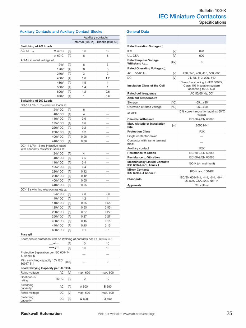
General Data
Rated Isolation Voltage Ui
IEC [V] 690
UL, CSA [V] 600
Rated Impulse VoltageWithstand Uimp
[kV] 6
Rated Operating Voltage Ue
AC 50/60 Hz [V] 230, 240, 400, 415, 500, 690
DC [V] 24, 48, 110, 220, 440
Insulation Class of the CoilClass F according to IEC 60085,
Class 105 insulation systemaccording to UL 508
Rated coil frequency AC 50/60 Hz, DC
Ambient Temperature
Storage [°C] -55…+80
Operation at rated voltage [°C] -25…+60
at 70°C 15% current reduction against 60°Cvalues
Climatic Withstand IEC 68-2/EN 60068
Max. Altitude of InstallationSite [m] 2000 NN
Protection Class IP2X
Single contactor cover —
Contactor with frame terminalblock —
Auxiliary contact IP2X
Resistance to Shock IEC 68-2/EN 60068
Resistance to Vibration IEC 68-2/EN 60068
Mechanically Linked ContactsIEC 60947-5-1, Annex L 100-K (on main unit)
Mirror ContactsIEC 60947-4 Annex F 100-K and 100-KF
Standards IEC/EN 60947-1, -4-1, -5-1, -5-4,UL 508, CSA 22.2. No. 14
Approvals CE, cULus
Auxiliary Contacts and Auxiliary Contact Blocks
Auxiliary contacts
Internal (100-K) Blocks (100-KF)
Switching of AC Loads
AC-12 Ith at 40°C [A] 10 10
at 60°C [A] 6 6
AC-15 at rated voltage of
24V [A] 6 3
120V [A] 6 3
240V [A] 3 2
400V [A] 1.8 1.2
480V [A] 1.5 1
500V [A] 1.4 1
600V [A] 1.2 0.6
690V [A] 1 0.6
Switching of DC Loads
DC-12 L/R< 1 ms resistive loads at
24V DC [A] 6 —
48V DC [A] 4 —
110V DC [A] 0.6 —
125V DC [A] 0.6 —
220V DC [A] 0.2 —
250V DC [A] 0.2 —
400V DC [A] 0.08 —
440V DC [A] 0.08 —
DC-14 L/R< 15 ms inductive loadswith economy resistor in series at
24V DC [A] 4 —
48V DC [A] 2.5 —
110V DC [A] 0.4 —
125V DC [A] 0.4 —
220V DC [A] 0.12 —
250V DC [A] 0.12 —
400V DC [A] 0.05 —
440V DC [A] 0.05 —
DC-13 switching electromagnets at
24V DC [A] 2.8 2.3
48V DC [A] 1.2 1
110V DC [A] 0.55 0.55
125V DC [A] 0.55 0.55
220V DC [A] 0.27 0.27
250V DC [A] 0.27 0.27
400V DC [A] 0.15 0.15
440V DC [A] 0.15 0.15
600V DC [A] 0.1 0.1
Fuse gG
Short-circuit protection with no Welding of contacts per IEC 60947-5-1
[A] 10 10
[A] 10 10
Protective Separation per IEC 60947-1, Annex N — —
Min. switching capacity 15V IEC60947-5-4 [mA] — 2
Load Carrying Capacity per UL/CSA
Rated voltage AC [V] max. 600 max. 600
Continuousrating 40 °C [A] 10 10
Switchingcapacity AC [A] A 600 B 600
Rated voltage DC [V] max. 600 max. 600
Switchingcapacity DC [A] Q 600 Q 600
Bulletin 100/104-K
IEC Miniature Contactors
26 Visit our website: www.ab.com/catalogs Rockwell Automation
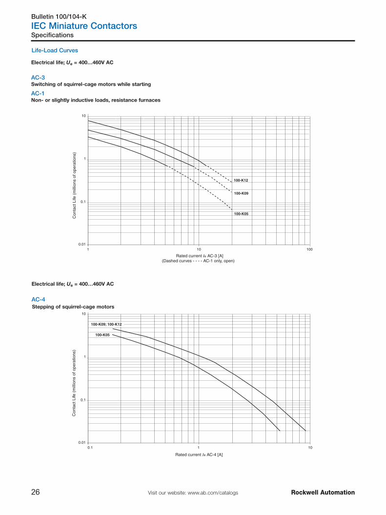
Life-Load Curves
Electrical life; Ue = 400…460V AC
AC-3Switching of squirrel-cage motors while starting
AC-1Non- or slightly inductive loads, resistance furnaces
Electrical life; Ue = 400…460V AC
AC-4Stepping of squirrel-cage motors
Specifications
0.010.1 1 10
1
0.1
10
100-K05
100-K09; 100-K12
Rated current Ie AC-4 [A]
Con
tact
Life
(m
illio
ns o
f ope
ratio
ns)
100-K05
100-K09
100-K12
0.011 10 100
1
0.1
10
Rated current Ie AC-3 [A](Dashed curves - - - - AC-1 only, open)
Con
tact
Life
(m
illio
ns o
f ope
ratio
ns)

Bulletin 700-K
IEC Miniature Control Relays
27Visit our website: www.ab.com/catalogsRockwell Automation
IEC Specifications
Specifications
700-K
AC-12 Rated Thermal CurrentAmbient temperature 40°C
Ith 24…240V [A] 10
230…500V [A] 10
230…690V [A] 10
Ambient temperature 60°C
Ith 24…240V [A] 6
230…500V [A] 6
230…690V [A] 6
AC-15/B600Switching of Solenoids and contactors
24V [A] 3
48V [A] 3
120V [A] 3
230V [A] 2
240V [A] 2
400V [A] 1.2
480V [A] 1
500V [A] 1
600V [A] 0.6
690V [A] 0.6
Short-circuit Protection"gG" Fuse acc. to IEC 60947-5-1, no welding of contacts
Fuse gG [A] 10
Min. Switching Capacity 15VFor bifurcated contacts (control relays and auxiliary contact blocks)
[mA] 2
Resistance and Power Dissipation
Main current circuitresistance, 1 pole [mΩ] 6.5
Power dissipation Ith, 4 poles [W] 2.6
Total power dissipation
IthAC control,
warm [W] 4.4
DC control,warm [W] 5.2
Lifespan
Mechanical [Mio. op.] 15
Electrical AC-15 (240V / 2 A) [Mio. op.] 0.7
Weight
AC control kg (lbs.) 0.16 (0.35)
DC control kg (lbs.) 0.2 (0.44)
Load Carrying Capacity per UL/CSA
Rated voltage AC [V] max. 600
Continuousrating 40 °C [A] 10
Switchingcapacity AC [A] B 600
Rated voltage DC [V] max. 600
Switchingcapacity DC [A] Q 600
700-K
Continuous Current
(General Purpose) 300V AC [A] 5
600V AC [A] 10
DC-13/Q600
1 pole 24V [A] 2.3
48V [A] 1
110V [A] 0.55
125V [A] 0.55
220V [A] 0.27
250V [A] 0.27
400V [A] 0.15
440V [A] 0.15
600V [A] 0.1

Bulletin 700-K
IEC Miniature Control Relays
28 Visit our website: www.ab.com/catalogs Rockwell Automation
General Data
Specifications
Cross Sections, Srew Type Terminals Coil Data
700-K
Rated Isolation Voltage Ui
IEC [V] 690
UL, CSA [V] 600
1 minute acc. to IEC 60947-5-1 [V] —
Rated Impulse Voltage Withstand Uimp [kV] 6
Rated Operating Voltage Ue
AC 50/60 Hz [V] 24, 48, 120, 230, 400, 500, 600, 690
DC [V] 24, 48, 110, 220, 440
Rated Coil Frequency AC 50/60 Hz, DC
Ambient Temperature
Storage [°C] -55…+80
Operation at rated voltage [°C] -25…+60
at 70°C 15% current reduction against 60°C values
Climatic Withstand —
Max. Altitude of Installation Site [m] 2000 NN
Protection Class IP2X
Auxiliary contact —
Standards IEC/EN 60947-1, -5-1, -5-4,UL 508, CSA 22.2. No. 14
Approvals CE, cULus
Conductor Cross Sections- Main Contacts and Auxiliary Contacts 700-K
Terminal type
�
Fine strandedwith ferrule
(1) Conductor(2) Conductors
[mm2][mm2]
0.75…2.50.75…2.5
Solid or coarsestranded
(1) Conductor(2) Conductors
[mm2][mm2]
1…40.75…2.5 + 1…4
Recommended torque [Nm] 1.2
Cross section per UL/CSA [AWG] 18…12 �
Recommended torque [lb-in] 10.6
� Pozidriv No. 2 / Blade No. 3 screw�Use same cross sections
700-K
Operating Limits
AC control50 Hz, 60 Hz, 50/60 Hz
pick-up [x Us] 0.85…1.1
dropout [x Us] 0.2…0.75
DC controlpick-up [x Us]
0.8…1.19, 12, 24, 110V DC:
0.7…1.25
dropout [x Us] 0.1…0.75
Coil Consumption
AC control 50 Hz, 60 Hz, 50/60 Hz
pick-up [VA/W] 35/32
hold-in [VA/W] 5/1.8
DC controlpick-up [W] cold 3.0, warm 2.6
hold-in [W] cold 3.0, warm 2.6
Operating Times
ACclosing delay [ms] 15…40
opening delay [ms] 15…33
With RC module opening delay [ms] 15…28
DCclosing delay [ms] 18…40
opening delay [ms] 6…12
With integrated diode opening delay [ms] 8…12
With external diode opening delay [ms] 35…50

Bulletin 193-K
IEC Miniature Thermal Overload Relays
29Visit our website: www.ab.com/catalogsRockwell Automation
Specifications
Specifications
Main Circuits
193-K
Rated Isolation Voltage Ui 690V
Rated Impulse Strength Uimp 6 kV
Rated Operating Voltage Ue IEC/UL 690V AC / 600V AC
Wiring cross sectionTerminal type
Terminal screws M3.5
Fine stranded withferrule [mm2] 2 x (1.5…4)
Solid or coarsestranded
[mm2][AWG]
2 x (1.5…4)2 x (16…10)
Recommended torque [Nm][lb-in]
1.210.6
Pozidriv screwdriver Size 2
Slotted screwdriver [mm] 1 x 6
Control Circuits
193-K
Rated Isolation Voltage Ui 690V AC
Rated Impulse Strength Uimp 4 kV AC
Rated Operating Voltage Ue IEC/UL 690V AC / 600V AC
Rating Designation A600 / Q300Rated Operating Current Ie N.O./N.C.
AC-15
24V [A] 4
240V [A] 2
400V [A] 1.6
690V [A] 0.15
DC-13
24V [A] 2
110V [A] 0.4
220V [A] 0.25
440V [A] 0.08
Thermal Current Ithe [A] 5
Short-circuit withstand, fuse gG [A] 6
Contact Reliability 15V, 2 mA
Wiring cross sectionTerminal type
Terminal screw M 3.5
Fine stranded withferrule [mm2] 2 x (1…4)
Solid or coarsestranded
[mm2][AWG]
2 x (1…4)2 x (18…12)
Recommended torque [Nm][lb-in]
1.210.6
Pozidriv screwdriver Size 2
Slotted screwdriver [mm] 1 x 6
General Data
193-K
Standards IEC/EN 60947-1, -4-1, -5-1,UL 508, CSA 22.2. No. 14
Certifications CE, cULus
Approximate Weights (unpackaged) 0.115 kg (0.25 lb)
Environmental Ratings
193-K
AmbientTemperature Storage
Operating-55…+80 °C (-67…+176 °F)-20…+60 °C (-4…+140 °F)
Humidity OperatingDamp Heat
5…95 % Non-condensingper IEC 68-2-3 and IEC 68-2-30
Vibration (per IEC 68-2-6) 3G
Shock (per IEC 68-2-27) 30G
Max. Altitude 2000 m
Pollution Environment Pollution Degree 3
Degree of Protection IP2X
Protection
Type of Relay Ambient Compensated, Time Delay,Phase Loss Sensitive
Nature of Relay Bimetallic Overload Relay
Trip Rating 120 % FLA
Trip Class IEC: 10A, UL 10
Reset Mode Automatic or Manual
Power dissipationup to 0.4 A 7 W
0.5…12.5 A 6 W
Bulletin 193-K
IEC Miniature Thermal Overload Relays
30 Visit our website: www.ab.com/catalogs Rockwell Automation
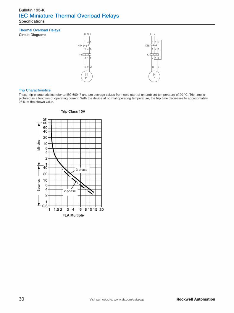
Trip Characteristics
Specifications
Thermal Overload RelaysCircuit Diagrams
These trip characteristics refer to IEC 60947 and are average values from cold start at an ambient temperature of 20 °C. Trip time ispictured as a function of operating current. With the device at normal operating temperature, the trip time decreases to approximately25% of the shown value.
FLA Multiple
2-phase
3-phase
Trip Class 10A
Sec
onds
Min
utes

Bulletin 100/104-K
IEC Miniature Contactors
31Visit our website: www.ab.com/catalogsRockwell Automation
Specifications/Approximate Dimensions
⊗ Coil Voltage Codes
Dimensions are shown in millimeters (inches). Dimensions are not intended for manufacturing purposes.
Bulletin 100-K, 700-K, 193-K Approximate Dimensions
49 (1-15/16)
4 (5/32)
108.2
(4-1
/4) 5
6 (
2-1
3/6
4)
54 (
2-1
/8)
35 (1-25/64)
44.9 (1-25/32)
50 (
1-3
1/3
2)
63.5 (2-1/2)
78.7 (3-7/64)
35.2 (1-25/64)
49.2
(1-1
5/1
6)
36.9 (1-29/64)
Mounting Position
DC Coil Voltages
[V] DC
9 ZR
12 ZQ
24 ZJ (DJ)�
30 ZC
36 ZW
48 ZY
60 ZZ
72 ZG
80 ZE
110 ZD
120 ZU
125 ZS
220 ZA
240 ZL
250 ZT
� (DJ): with integrated Diode
AC Coil Voltages
[V] 50 Hz 60 Hz 50/60 Hz
12 — — KQ
24 — — KJ (WJ)�
32 — — VU
36 — — KV
42 — — KW
48 — — KY
60 — — KR
70 — — VG
110 D (WD)� — —
120 — D (WD)� —
127 — — VS
135 — — VE
200 KG — —
200-220 — — KG
230 — — KF (WF)�
240 — — KA
250 — — VT
380-400 N — —
400 — — KN
415 — — KU
440 B — —
480 — B —
500 M — —
525 VC — —
575 — M —
600 — VC —
Voltage codes in bold are prefered products. For availabilty ofother voltage codes, please consult your local Allen-Bradleydistributor or representative.� (Wx): with built-in Varistor
Without accessories
25° 25°
12 (15/32)* 360°
� Minimum distance to grounded parts or walls

General Terms and Conditions of Sale
32 Visit our website: www.ab.com/catalogs Rockwell Automation
TERMS AND CONDITIONS«General Terms and Conditions of Sale» can be found in publication «6500(EN) - January 2004».This publication is available as a PDF file (Adobe Acrobat) athttp://www.rockwellautomation.com/termsofsale

Notes
33Visit our website: www.ab.com/catalogsRockwell Automation

Notes
34 Visit our website: www.ab.com/catalogs Rockwell Automation


Publication MCS-SG001A-EN-P – April 2007 ©2006 Rockwell Automation, Inc. All Rights Reserved. Printed in Switzerland.