
9 WATER SUPPLY - Tasman
51
Tasman District Council - Engineering Standards & Policies 2013 Section 9 Water Supply – Page 1 9 WATER SUPPLY 9.1 Introduction The purpose of Council’s water supply engineering standards is to provide design guidance and minimum standards for the design, construction and maintenance of water supply reticulation. Design and construction of all water supply works in accordance with these standards will ensure that water is supplied to communities effectively and in a way that is cost-effective in the long-term. 9.1.1 Objectives Council is responsible for all water supply infrastructure assets under its control. It is Council’s intention that all parts of the water supply system meet the following objectives: a) Water is supplied to communities in a way that adequately meets their demand supply volume at a minimum water pressure; b) The quality of water meets minimum standards for drinking water quality; c) Water is provided in a safe and reliable manner for fire fighting purposes d) The water supply network is durable and robust; e) The water supply network is designed, constructed and maintained to a high standard to minimise risk; f) The water supply network is easily accessible for maintenance and replacement works as required; g) The water supply network meets the needs and expectations of the community in terms of the Council’s Long Term Plan. 9.1.2 Key References Table 9-1 sets out external standards that are relevant to the management of water. These apply and must be taken into account in the design and construction of any water supply asset in the Tasman District.
Transcript of 9 WATER SUPPLY - Tasman

Tasman District Council - Engineering Standards & Policies 2013 Section 9 Water Supply – Page 1
9 WATER SUPPLY 9.1 Introduction The purpose of Council’s water supply engineering standards is to provide design guidance and minimum standards for the design, construction and maintenance of water supply reticulation. Design and construction of all water supply works in accordance with these standards will ensure that water is supplied to communities effectively and in a way that is cost-effective in the long-term.
9.1.1 Objectives
Council is responsible for all water supply infrastructure assets under its control. It is Council’s intention that all parts of the water supply system meet the following objectives: a) Water is supplied to communities in a way that adequately meets their demand
supply volume at a minimum water pressure; b) The quality of water meets minimum standards for drinking water quality;
c) Water is provided in a safe and reliable manner for fire fighting purposes
d) The water supply network is durable and robust;
e) The water supply network is designed, constructed and maintained to a high
standard to minimise risk;
f) The water supply network is easily accessible for maintenance and replacement works as required;
g) The water supply network meets the needs and expectations of the community in
terms of the Council’s Long Term Plan.
9.1.2 Key References
Table 9-1 sets out external standards that are relevant to the management of water. These apply and must be taken into account in the design and construction of any water supply asset in the Tasman District.
Tasman District Council - Engineering Standards & Policies 2013 Section 9 Water Supply – Page 2
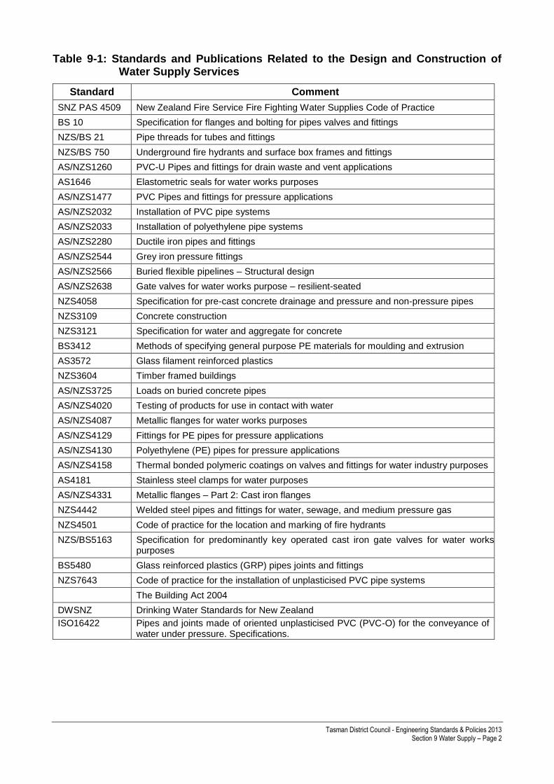
Table 9-1: Standards and Publications Related to the Design and Construction of Water Supply Services
Standard Comment
SNZ PAS 4509 New Zealand Fire Service Fire Fighting Water Supplies Code of Practice
BS 10 Specification for flanges and bolting for pipes valves and fittings
NZS/BS 21 Pipe threads for tubes and fittings
NZS/BS 750 Underground fire hydrants and surface box frames and fittings
AS/NZS1260 PVC-U Pipes and fittings for drain waste and vent applications
AS1646 Elastometric seals for water works purposes
AS/NZS1477 PVC Pipes and fittings for pressure applications
AS/NZS2032 Installation of PVC pipe systems
AS/NZS2033 Installation of polyethylene pipe systems
AS/NZS2280 Ductile iron pipes and fittings
AS/NZS2544 Grey iron pressure fittings
AS/NZS2566 Buried flexible pipelines – Structural design
AS/NZS2638 Gate valves for water works purpose – resilient-seated
NZS4058 Specification for pre-cast concrete drainage and pressure and non-pressure pipes
NZS3109 Concrete construction
NZS3121 Specification for water and aggregate for concrete
BS3412 Methods of specifying general purpose PE materials for moulding and extrusion
AS3572 Glass filament reinforced plastics
NZS3604 Timber framed buildings
AS/NZS3725 Loads on buried concrete pipes
AS/NZS4020 Testing of products for use in contact with water
AS/NZS4087 Metallic flanges for water works purposes
AS/NZS4129 Fittings for PE pipes for pressure applications
AS/NZS4130 Polyethylene (PE) pipes for pressure applications
AS/NZS4158 Thermal bonded polymeric coatings on valves and fittings for water industry purposes
AS4181 Stainless steel clamps for water purposes
AS/NZS4331 Metallic flanges – Part 2: Cast iron flanges
NZS4442 Welded steel pipes and fittings for water, sewage, and medium pressure gas
NZS4501 Code of practice for the location and marking of fire hydrants
NZS/BS5163 Specification for predominantly key operated cast iron gate valves for water works purposes
BS5480 Glass reinforced plastics (GRP) pipes joints and fittings
NZS7643 Code of practice for the installation of unplasticised PVC pipe systems
The Building Act 2004
DWSNZ Drinking Water Standards for New Zealand
ISO16422 Pipes and joints made of oriented unplasticised PVC (PVC-O) for the conveyance of water under pressure. Specifications.
Tasman District Council - Engineering Standards & Policies 2013 Section 9 Water Supply – Page 3
9.2 Reticulation design
9.2.1 Level of Service
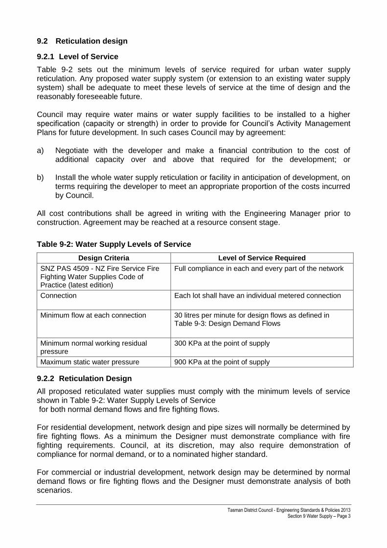
Table 9-2 sets out the minimum levels of service required for urban water supply reticulation. Any proposed water supply system (or extension to an existing water supply system) shall be adequate to meet these levels of service at the time of design and the reasonably foreseeable future. Council may require water mains or water supply facilities to be installed to a higher specification (capacity or strength) in order to provide for Council’s Activity Management Plans for future development. In such cases Council may by agreement: a) Negotiate with the developer and make a financial contribution to the cost of
additional capacity over and above that required for the development; or
b) Install the whole water supply reticulation or facility in anticipation of development, on terms requiring the developer to meet an appropriate proportion of the costs incurred by Council.
All cost contributions shall be agreed in writing with the Engineering Manager prior to construction. Agreement may be reached at a resource consent stage.
Table 9-2: Water Supply Levels of Service
Design Criteria Level of Service Required
SNZ PAS 4509 - NZ Fire Service Fire Fighting Water Supplies Code of Practice (latest edition)
Full compliance in each and every part of the network
Connection
Each lot shall have an individual metered connection
Minimum flow at each connection
30 litres per minute for design flows as defined in Table 9-3: Design Demand Flows
Minimum normal working residual pressure
300 KPa at the point of supply
Maximum static water pressure 900 KPa at the point of supply
9.2.2 Reticulation Design
All proposed reticulated water supplies must comply with the minimum levels of service shown in Table 9-2: Water Supply Levels of Service for both normal demand flows and fire fighting flows. For residential development, network design and pipe sizes will normally be determined by fire fighting flows. As a minimum the Designer must demonstrate compliance with fire fighting requirements. Council, at its discretion, may also require demonstration of compliance for normal demand, or to a nominated higher standard. For commercial or industrial development, network design may be determined by normal demand flows or fire fighting flows and the Designer must demonstrate analysis of both scenarios.
Tasman District Council - Engineering Standards & Policies 2013 Section 9 Water Supply – Page 4
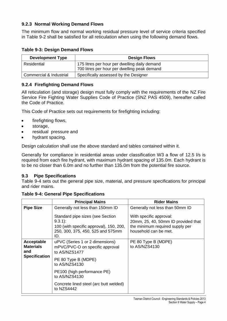
9.2.3 Normal Working Demand Flows
The minimum flow and normal working residual pressure level of service criteria specified in Table 9-2 shall be satisfied for all reticulation when using the following demand flows.
Table 9-3: Design Demand Flows
Development Type Design Flows
Residential 175 litres per hour per dwelling daily demand 700 litres per hour per dwelling peak demand
Commercial & Industrial Specifically assessed by the Designer
9.2.4 Firefighting Demand Flows
All reticulation (and storage) design must fully comply with the requirements of the NZ Fire Service Fire Fighting Water Supplies Code of Practice (SNZ PAS 4509), hereafter called the Code of Practice.
This Code of Practice sets out requirements for firefighting including:
firefighting flows,
storage,
residual pressure and
hydrant spacing.
Design calculation shall use the above standard and tables contained within it.
Generally for compliance in residential areas under classification W3 a flow of 12.5 l/s is required from each fire hydrant, with maximum hydrant spacing of 135.0m. Each hydrant is to be no closer than 6.0m and no further than 135.0m from the potential fire source. 9.3 Pipe Specifications Table 9-4 sets out the general pipe size, material, and pressure specifications for principal and rider mains.
Table 9-4: General Pipe Specifications
Principal Mains Rider Mains
Pipe Size Generally not less than 150mm ID
Standard pipe sizes (see Section 9.3.1):
100 (with specific approval), 150, 200, 250, 300, 375, 450, 525 and 575mm ID.
Generally not less than 50mm ID
With specific approval:
20mm, 25, 40, 50mm ID provided that the minimum required supply per household can be met.
Acceptable Materials and Specification
uPVC (Series 1 or 2 dimensions)
mPVC/PVC-O on specific approval
to AS/NZS1477
PE 80 Type B (MDPE) to AS/NZS4130
PE100 (high performance PE) to AS/NZS4130
Concrete lined steel (arc butt welded) to NZS4442
PE 80 Type B (MDPE) to AS/NZS4130

Tasman District Council - Engineering Standards & Policies 2013 Section 9 Water Supply – Page 5
Principal Mains Rider Mains
Ductile iron to AS/NZS2280
Hobas GR to AS3572
Pressure class
No less than PN12 (Class D)
A higher class may be required in some instances.
9.3.1 Pipe Size
By convention, PVC pressure pipes in New Zealand and Australia are usually referred to by their nominal internal diameter (ie, DN50, 100, 150 etc) whereas the equivalent size ISO dimension PE pipes are usually referred to and specified by their nominal outside diameter (ie,63, 125, 180 OD). These standards generally refer to pipe dimensions by internal diameter (ID). In any instance where an external diameter is shown on a drawing or specified it shall be annotated “OD”. Dimensions in absence of either “ID” or “OD” shall be assumed by Council to refer to an internal diameter. Minimum and standard pipe sizes for principal and rider mains are shown in Table 9-4: General Pipe Specifications . PVC pipes should generally be specified in metric sizes, but imperial sizes may be required in some instances to achieve compatibility with Council’s existing pipe system. Principal mains shall be generally no less than 150mm ID. Table 9-5 sets out instances where smaller principal mains may be permitted, but subject to the levels of service specified in Table 9-2.
Table 9-5: Reduced dimension principal mains
Size of Principal Main (generally uPVC Class D)
Maximum Length
Connected to larger main at one end
Connected to larger main at both ends
100mm ID 135 m 400 m
Rider mains shall be generally not less than 50mm ID. Table 9-6 sets out instances where smaller rider mains may be permitted, but subject to the levels of service specified in Table 9-2.
Table 9-6: Reduced dimension rider mains
Size of Rider Main
(minimum PE80 MDPE Class D)
Maximum Number of Domestic Service Connections (Home Units not Lots)
Connected to larger main at one end
Connected to larger main at both ends
20mm ID (25mm OD) 1 N/A
25mm ID (32mm OD) 5 10
40mm ID (50mm OD) 10 20
50mm ID (63mm OD) 15 32
9.3.2 Pipe Materials
uPVC pipes are acceptable in all normal circumstances for principal mains. mPVC and PVC-O pipes may be approved on application. The installation shall be to AS/NZS2032

Tasman District Council - Engineering Standards & Policies 2013 Section 9 Water Supply – Page 6
and AS/NZS2566, with particular attention to the anchoring of valves and hydrants against displacement in operation. Refer TDC Drawings 900 and 901. PE pipes shall be normally used in all rider mains. PE pipes may be appropriate for principal mains in special cases and shall require specific approval by the Engineering Manager. For PE pipes generally PE80 material is the standard used; however PE100 may be used where higher pipe strength is required or increased capacity is an important criterion. Pipes of differing compositions shall not be mixed within a common pipe length, (ie, valve-to-valve). Installation of PE pipes shall be to AS/NZS2033 and AS/NZS2566. Concrete lined steel pipes may be required in potentially unstable ground, for lengths of exposed pipe, or in other special cases, and shall be the subject of specific design. Suitable corrosion protection shall be provided. Steel pipes laid underground shall have an extruded blue or black HDPE external coating. Pipe laid above ground shall have a black HDPE coating or shall have an approved epoxy coating applied by a specialist applicator. Ductile iron pipes may be appropriate in special cases and shall require specific approval of Council. Ductile iron pipes shall be sleeved with a polythene sleeve. 9.4 Pipe Joints
9.4.1 Connection of Rider Mains to Principal Main
Where a rider main is to be extended at right angles to a principal main, it shall normally be connected with a tapping band without ferrule (TDC Drawing 910), where the size of the principal main and rider main allow this, otherwise an elongated gibault is to be used (TDC Drawing 901). Where a rider main is to be extended along the same alignment beyond the end of the principal main, it shall normally be connected in a similar manner (TDC Drawing 910) with an anchored blank end plate, and with a vertical socket and right angle (De-zincification resistant) bronze bend.
9.4.2 Unrestrained Mechanical Couplings
Unrestrained mechanical couplings shall be designed for a 50-year life and to the required Australian/New Zealand Standard.
9.4.3 PVC Pipe Joints
Joints for uPVC pipes shall be spigot and socket rubber ring type (z joints) and a biocidal lubricant. Elastometric seal rings shall conform to NZS/BS 2494 or AS 1646.
9.4.4 PE Pipe Joints
All PE pipe less than 100mm ID (125mm OD) shall be jointed by seal ring compression joints to AS/NZS4129, appropriate for the type of pipe (eg, “Philmac”) and rated to PN16 maximum working pressure. Pipes greater than 100mm ID (125mm OD) may be jointed by the use of a butt welding or electrofusion technique. Electrofusion fittings shall conform to AS/NZS4129.

Tasman District Council - Engineering Standards & Policies 2013 Section 9 Water Supply – Page 7
The pipes shall be installed in accordance with AS2033 and AS/NZS2566. Certified tradespersons approved by Council, shall be employed with equipment specifically designed for the task. The contractor shall provide their own power source and earth leakage protection for the safety of their personnel. For electrofusion jointing only personnel trained and holding a current certificate of competency in the system to be used, will be permitted by Council to carry out the work.
9.4.5 Welded Steel Pipe Joints
Welded joints in steel pipes shall be either butt joints, with an external welding band, spigot and socket joints, or as otherwise approved by Council. All welds shall be fillet welds of 7mm or larger, applied in the field. Flange joints shall be to AS/NZS4087. Where butt jointed pipes are used the ends shall be neatly butted where possible with a seal weld applied from the outside before the welding band is affixed. Steel pipes shall be cut to a neat and true line with an abrasive saw. After welding and testing (if required) all unprotected metal inside and outside shall be thoroughly cleaned by appropriate methods. The exposed steel shall be protected promptly and damaged protective coating repaired in an approved manner by the application of one of the treatments listed below: a) Emer-tan rust converter; Emer-guard primer; Emer-clad membrane, or b) Polyken Synergy™ which includes an appropriate primer coat, or c) Carbomastic 15 primer; Servi-Wrap R15A membrane; Servi-Wrap Outerwrap. Joints shall be internally protected with a mortar lining to give a smooth internal bore. Materials for the mortar shall comply with the requirements of NZS3121. It is important to get a satisfactory mortar consistency to prevent the mortar from sagging or dropping out. The pipe joint shall be plugged with a suitable plunger prior to applying the mortar and then withdrawn evenly to smooth out the mortar joint. Epoxy mortar (suitable with potable water) shall be used for making good the mortar lining where pipes have been cut for mitred joints, or the fitting of flanges etc.
9.4.6 Gibault Joints
Gibault joints shall only be used with specific approval. This will generally be for connection to existing principal mains where no feasible alternative is available (such as for repair of asbestos cement or PVC pipe). 9.5 Fittings
9.5.1 Pipe Fittings
The following standards apply to pipe fittings:

Tasman District Council - Engineering Standards & Policies 2013 Section 9 Water Supply – Page 8
a) Ductile iron and cast iron fittings such as tees, hydrant tees, crosses, tapers, hydrant risers, blank caps, plugs and bends shall be blue nylon coated in accordance with AS/NZS4158. Where uPVC or polythene pipe is used, the respective purpose-made fittings shall be used. Bends shall be Z ring, swept bends; solvent cement and elbow bends shall not be used
b) Flanges shall be to Table 9 of AS/NZS4331.2 and BS10. Fittings laid adjacent to
other fittings shall have flanges.
c) All bolts, nuts and washers shall be 316 stainless steel with molybond anti galling coating.
d) Graphite greases, packing and compounds shall not be used in contact with stainless
steel.
e) Where dissimilar metals are used, purpose-made delrin thermoplastic inserts shall be installed in the flanges to prevent electrolytic action.
f) Where fittings are used which do not have bolts, nuts and washers which are 316
stainless steel or fittings which are non-nylon coated in accordance with the Australian/New Zealand standards, then these fittings shall be wrapped as detailed in TDC Drawings 905 and 906.
9.5.2 Corrosion Protection
These standards apply to the protection of flange and unrestrained mechanical couplings:
a) Protection shall normally be provided by the use of 316 stainless steel bolts, nuts and washers and fittings coated to Australian/New Zealand standards
b) Where metallic pipes and fittings are not coated delrin thermoplastic inserts shall be
installed in the flange to prevent electrolytic action. Steel and grey cast iron flanges shall be further protected by a wrapping system.
c) Corrosion protection will be required (as follows) for all new flange and unrestrained
mechanical couplings, where materials other than 316 stainless steel and coatings to Australian/New Zealand standards are used.
d) For flanges see TDC Drawing 905. For Unrestrained Mechanical Couplings see TDC
Drawing 906.
9.5.3 Hydrants
The following standards must be met in respect of supply hydrants: a) Fire hydrants shall be installed on all principal mains in accordance with the
requirements of the New Zealand Fire Service Code of Practice.
b) Hydrants must be readily accessible for fire appliances and should generally be positioned near road/street intersections in conjunction with valves.
c) A fire hydrant shall be located at each road/street intersection and not be positioned
closer than 6.0m from any dwelling.

Tasman District Council - Engineering Standards & Policies 2013 Section 9 Water Supply – Page 9
d) In a cul-de-sac or other terminal streets, the last hydrant shall be at the head of the cul-de-sac.
e) The distance between the hydrants and from the hydrants to the furthest building platform shall not exceed 135.0m.
f) Where a residential private way is more than 65m long, a hydrant shall be sited 20m either side of the right-of-way/access, or on the other side of the road/street immediately opposite the entrance where practical. A principal main shall be constructed and hydrant(s) placed within the private access way in order to ensure each building is within a distance of a fire hydrant as specified above. The width of the private access way shall be no less than 3.0m and sufficient to enable a fire appliance access to the hydrant.
g) Should a fire hydrant be approved by Council up a private way, then Council will
require an Easement In Gross in favour of Council over that line from the principal main to the hydrant.
h) Hydrants shall be screw-down type to BS 750. Normally the medium pattern shall be
used, except where Council may approve or require the tall pattern for extra flow capacity. Hydrants shall not be self-draining. Hydrants shall be blue nylon coated inside and out (location dependent) and be clockwise closing.
i) In some high risk areas hydrants shall be installed in pairs to provide better water
flows.
j) Hydrant tees shall be flanged if laid next to other fittings. Otherwise flexible Z ring joints are permitted. Refer TDC Drawings 900 and 903.
k) Hydrant risers shall be used or the water main laid deeper where necessary, in order to ensure that the top of the spindle is between 150mm and 250mm below finished surface level.
l) Hydrants shall be installed so the spindle cap and riser connection are in line with the
water main below.
m) The manufacture and installation of hydrant boxes shall be to BS 750. Hydrant boxes shall be aligned in the direction of the water main. Heavy pattern hydrant boxes shall be used.
n) Hydrants shall be marked in accordance with SNZ PAS 4509 Appendix G. Hydrants
shall be marked in accordance with NZS4501 with raised blue reflectorised markers together with painted triangle and painted fire hydrant box and circle as shown on TDC Drawing 907.
o) Hydrant boxes shall be set on approved pre-cast concrete sections down to the level
of the hydrant base flange, placed so as not to transfer loads to the mains.
p) All surface boxes shall be left 10mm proud of the adjacent seal in new vested roads, otherwise flush with the final ground/sealed surface.

Tasman District Council - Engineering Standards & Policies 2013 Section 9 Water Supply – Page 10
9.5.4 Positioning of Valves
a) Valves shall generally be placed on all the three legs of a tee intersection to optimise control of the water supply system and minimise the number of customers without water in case of a shut-down. Where practical, valves shall be located in berms.
b) Sluice valves shall be flanged and bolted to each leg of the “tee” to form a single assembly. A hydrant will be included between the valves.
c) Line valves shall be installed where the distance between other control valves exceeds 250m. For water mains over 200mm diameter, line valves shall be required every 450m and shall be positioned as agreed by Council. Rider mains shall have valves at both ends, located as close to the principal main as practical, but within the berm or footpath.
9.5.5 Sluice Valves
a) The valves on all principal water mains shall comply with AS2638.2, Class 16 (a class higher than 16 may be required in certain circumstances). Valves shall be resilient seated and anti clockwise closing with a stem sealed by “o” rings capable of being replaced under pressure. They shall have external and internal polymeric coating to AS/NZS4158, be pressure rated to PN16 and be flanged.
b) Specific design, subject to the approval of Council, shall be required for valves over 250mm NB.
c) The valve shall be capable of bi-directional flow of water. Valves shall be set so that the spindle is truly vertical. Bolted joints shall be wrapped with a wrapping system, see TDC Drawings 905 to 906.
d) Sluice valves shall be installed in accordance with TDC Drawings 902 and 904 and
shall be marked as per TDC Drawing 907.
e) Approval of any particular sluice or gate valve shall be entirely at the discretion of the Engineering Manager.
9.5.6 Rider Main Valves
Valves on rider mains shall be approved high quality gate valves, be clockwise closing, comply with BS 5154, have a pressure rating of PN16 or better, have a hand wheel with open spokes and protective coating made of either cast iron or malleable iron. They shall have a body manufactured from cast bronze with all other components from DR copper alloy or grade 316 stainless steel and be indelibly marked with manufacturer’s identity, pressure rating, size, and stamped “DR”.
9.5.7 Air Release Valves
a) Water mains shall be laid to grade such that, for the purpose of the release of the air, a fire hydrant, an automatic air valve or a 20mm diameter ferrule and gate valve in a permanent surface box shall be installed at high points or in locations required by Council. They shall be installed so that ground water cannot enter the main at negative main pressure.
b) Automatic air valves shall an approved valve, single or double, large or small orifice, and of appropriate nominal bore. Automatic air valves shall be flanged and be

Tasman District Council - Engineering Standards & Policies 2013 Section 9 Water Supply – Page 11
mounted on flanged risers with an integral isolating valve accessible from ground level. Automatic air valves shall be installed within a standard manhole with positive drainage to an outlet such that ground water cannot enter the main at negative mains pressure.
9.5.8 Scour Valves
a) Scour valves shall be either a fire hydrant or valve as for air release above and shall be installed at low points or to facilitate draining of a water main where required by Council.
b) All dead end mains or rider mains shall be fitted with permanent scour valves complete with valve box.
c) In areas where the scouring of mains is needed as a frequent operation, a connection to the stormwater kerb outlets, open channels or sumps shall be provided. The connection of a scour valve to stormwater pipes or manholes is not permitted.
d) The box shall be similar to a fire hydrant box but shall be marked “AV” rather than “FH”.
9.5.9 Butterfly Valves
Butterfly valves shall only be used with the specific approval of Council. Butterfly valves shall be located in concrete valve chambers.
9.5.10 Non-Return Valves
a) Non-return valves shall be installed at reservoir and tank outlets and at reservoir inlets and at the lower extremity of the tank reticulation zone.
b) 50mm diameter swing check valves shall be an approved bronze valve. Valves larger than 50mm diameter shall be approved swing check valves, with external arm. Non-return valves shall be capable of being serviced without removal from the main. Cast iron swing check valves shall be fusion bonded thermoplastic coated or epoxy coated. All coatings shall be compatible with potable water and shall be coloured blue.
c) Below ground swing check valves shall be within a standard manhole.
d) “Wafer” check valves may be approved for specific applications.
9.5.11 Valve Boxes
a) All valves shall be fitted with an approved square pattern cast iron surface box with the lid marked “SV” or “V” and a 150mm lid on a PVC riser pipe. Heavy duty lids shall be used in trafficable areas.
b) The riser pipe shall extend from the valve bonnet to 80mm below the finished surface and be placed vertically over the valve. The valve box shall be supported on a firm foundation so that no direct loading is transmitted from the box to the main or riser.

Tasman District Council - Engineering Standards & Policies 2013 Section 9 Water Supply – Page 12
c) Valve surface boxes shall be left 10mm proud of seal in newly formed road carriageways and flush with finished surfaces in all other instances.
d) If the distance between the finished surface level and the top of the valve is greater than 900mm, a valve key extension shall be fitted.
e) Valve boxes shall be painted white with a 300mm wide kerb flash adjacent to the valve. See TDC Drawing 907.
9.6 Anchorage and Thrust Blocks a) Cast in-situ concrete anchor blocks shall be provided on mains 50mm ID or greater,
at all points where an unbalanced thrust occurs. This shall include all bends, tapers, valves, pressure reducing valves, tees and blank ends.
b) For butt welded and electrofused PE pipework up to 150mm ID, anchor blocks are not required. Where PE pipes connect to other pipework or fittings with flexible joints, anchor blocks are required.
c) The design of anchor blocks shall be based on “good ground” soil bearing capacity
(as defined in NZS3604) or the ultimate bearing capacity of the site soils, whichever is lesser. A safety factor of between 1.5 and 2 shall be used in the design. Anchor block bearing area calculations shall be submitted with the engineering plans for checking and approval.
d) The inner face of the block shall not be of a lesser thickness than the diameter of the
fittings, and shall be so constructed as not to impair access to the bolts on the fittings. Concrete shall have a minimum compressive strength of 17.5mPa at twenty eight (28) days.
e) All concrete blocks shall be cast in-situ. Pre-cast concrete blocks are not permitted.
f) A protective membrane of not less than three layers of 250 micron polythene sheet or similar shall be provided between the pipe (irrespective of the pipe material) and the concrete anchor and thrust blocks to prevent abrasive damage to the water main.
g) Valves and hydrants on uPVC pipe lines require anchorage to resist torque when the valve is operated.
h) Valves shall be anchored as shown on TDC Drawing 904. A fish-tailed galvanised flat steel bar shall be attached to the bottom bolt on each flange of the valve and incorporated into a cast in-situ concrete pad 200mm deep, of the same width as the trench and extending 150mm beyond each anchor bar. Care shall be taken to ensure that all bolts can be removed for future maintenance and are not obstructed by concrete.
i) Hydrant tees, when flanged, shall be anchored as valves – refer TDC Drawing 904.
j) Hydrant tees with rubber ring joints shall be anchored as shown on TDC Drawing 903. The tee shall be anchored by in a concrete pad 200mm deep, of the same width as the trench and not extending beyond the length of the tee. Care shall be taken to ensure that the flexible joints are not encased.
Tasman District Council - Engineering Standards & Policies 2013 Section 9 Water Supply – Page 13
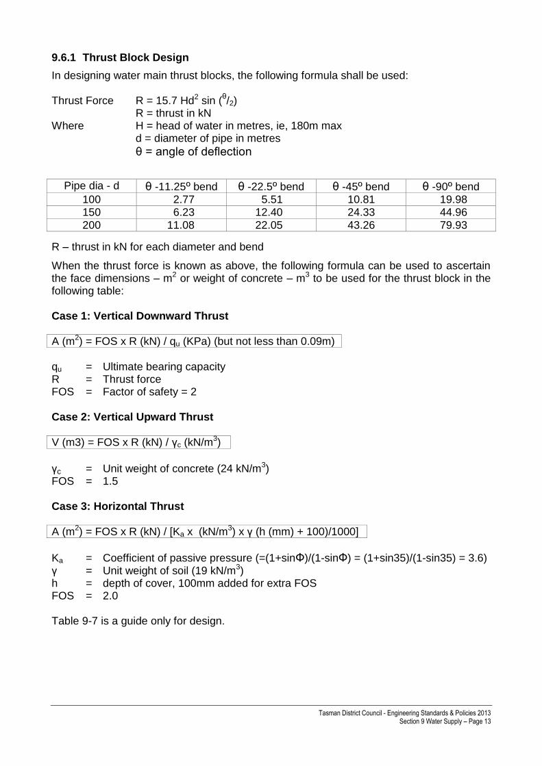
9.6.1 Thrust Block Design
In designing water main thrust blocks, the following formula shall be used:
Thrust Force R = 15.7 Hd2 sin (θ/2)
R = thrust in kN Where H = head of water in metres, ie, 180m max d = diameter of pipe in metres
θ = angle of deflection
Pipe dia - d θ -11.25º bend θ -22.5º bend θ -45º bend θ -90º bend
100 2.77 5.51 10.81 19.98 150 6.23 12.40 24.33 44.96
200 11.08 22.05 43.26 79.93
R – thrust in kN for each diameter and bend
When the thrust force is known as above, the following formula can be used to ascertain the face dimensions – m2 or weight of concrete – m3 to be used for the thrust block in the following table: Case 1: Vertical Downward Thrust A (m2) = FOS x R (kN) / qu (KPa) (but not less than 0.09m) qu = Ultimate bearing capacity R = Thrust force FOS = Factor of safety = 2 Case 2: Vertical Upward Thrust V (m3) = FOS x R (kN) / γc (kN/m3)
γc = Unit weight of concrete (24 kN/m3) FOS = 1.5 Case 3: Horizontal Thrust A (m2) = FOS x R (kN) / [Ka x (kN/m3) x γ (h (mm) + 100)/1000]
Ka = Coefficient of passive pressure (=(1+sinФ)/(1-sinФ) = (1+sin35)/(1-sin35) = 3.6) γ = Unit weight of soil (19 kN/m3) h = depth of cover, 100mm added for extra FOS FOS = 2.0 Table 9-7 is a guide only for design.

Tasman District Council - Engineering Standards & Policies 2013 Section 9 Water Supply – Page 14
Table 9-7: Pipe Thrust Design
Pipe
diameter Face area m
2 or m
3
11.25º
Angle of deflection
22.5º
Angle of deflection
45º
Angle of deflection
90º
Angle of deflection
Vert
ica
l
dow
nw
ard
thru
st
100
150
200
m2
m2
m2
0.09*
0.09*
0.09*
0.09*
0.09*
0.15
0.09*
0.16
0.29
0.13
0.30
0.53
Vert
ica
l
upw
ard
thru
st
100
150
200
m3
m3
m3
0.17
0.39
0.69
0.34
0.74
1.34
0.68
1.52
2.70
1.25
2.81
5.00
Horizonta
l
sid
ew
ays
thru
st
100
150
200
m2
m2
m2
0.12
0.26
0.46
0.23
0.52
0.92
0.45
1.02
1.81
0.83
1.88
3.34
Notes 1.* Minimum thrust block size 300 x 300 x 300 2. Table is a guide only 3. Soil parameters are classed as “good ground” in accordance with NZS3604. 4. Test head 180m and factor of safety of 2 for all applications. 9.7 Water Supply Connections
9.7.1 Point of supply
The point of metering will be the point of supply. The point at which the private supply line connects to the meter outlet is designated as the point at which Council’s responsibility for supply ceases and the property owner’s responsibility for repairs and maintenance begins. TDC Drawings 909 and 911 illustrate the point of supply for a number of instances. Each individual dwelling or unit shall have a single point of water supply and a meter immediately adjacent to the road boundary. For rear lots, the point of metering shall be at or adjacent to the road entrance to the property, with separate, private, supply lines laid in the access strip or right-of-way to the lots being serviced. Premises of multiple ownership (including body corporate, strata title and leasehold or tenancy-in-common scheme) shall be supplied and metered in accordance with TDC Drawing 911. The supply pipe for one lot shall not pass through another lot unless there is physically no alternative (eg no water main in the road/street or insufficient water pressure in the main at the road/street boundary). In such a case an easement shall be required to protect the line of the supply pipe.

Tasman District Council - Engineering Standards & Policies 2013 Section 9 Water Supply – Page 15
Thread sealing PTFE thread seal tape is only permitted on plastic threads. All metal threads shall be sealed with hemp and graphite jointing compound.
9.7.2 Approved Connections
Table 9-8 lists approved water supply connection assemblies.
Table 9-8: Approved Connections
Connection size
Valve Backflow preventer
Meter Meter box
20mm ID* 25mm ID
Acuflo GM900S MKII manifold assembly
Acuflo GM900S MKII manifold assembly
Ivensys/Senus 620 M or Kent Esler MSM. Meters to have a current pattern approval certificate to OIML R49 (Q3 2.5 with a Q1/Q3 ratio of not less than R160.
Acuflo AMB300 box AMB006 base
40mm ID 50mm ID
Approved gate valve
“Wilkins” 950
‘Wilkins’ 975 (RPZ protection)
Kent Helix combination meter or similar approval
Approved box and base
80mm ID 100mm ID 150mm ID
Approved sluice valve at main and meter
Approved backflow preventer
Kent Helix combination meter or similar approval
Approved box and base
*A 20mm ID connection may not be adequate for residential fire sprinkler systems.
9.7.3 Connection Type
Service connection pipes shall be PE80 Type B (MDPE), minimum PN12 pressure rating, complying with AS/NZS4130 and coloured blue. Each service connection to a principal main or a rider main shall be by means of a tapping band and a “Talbot” swivel ferrule, with the flow of water controlled by a screwed brass plug. Refer TDC Drawings 909 and 910.
Tapping bands shall be made of LG2 gunmetal with captivated 316 stainless steel bolts and nuts. The band shall have a nitrite rubber sealing ring secured in a recess to prevent blow out under pressure. When tightening the pipe, the upper and lower halves shall make face-to-face contact. The band shall have clear identification of manufacturer, nominal pipe size and pipe material and stamped D/R and be corrosion protected.
If the required connection is larger than is possible to connect with a tapping band (refer Table 9-9), the main connection shall be by a tee or a tapped elongated joint having a vertically connected ferrule. Connections larger than 50mm ID shall be by tee with an additional sluice valve at the main. Table 9-9 specifies the maximum size of rider main connections using a standard tapping band.
Table 9-9: Maximum Ferrule for Service Connections
Diameter of Main Max Size of Ferrule
38mm 12mm
50mm 19mm
100mm 25mm

Tasman District Council - Engineering Standards & Policies 2013 Section 9 Water Supply – Page 16
150mm 32mm
200-450mm To be determined
9.7.4 Backflow Prevention
a) Backflow prevention devices are required to be installed on all connections including private residential connections. The minimum standard of backflow prevention on any connection shall be a non-testable double check valve fitted downstream of an approved strainer.
b) All new industrial and commercial properties shall have an approved backflow preventer installed at the boundary and available for inspection at all times. It shall be installed in accordance with the manufacturer’s specification, in a steel mesh frame with locking lid. The type and location of backflow preventers shall comply with the Building Act and Water Supply Protection Regulations 1961. The type of back flow (RPZ, double check valve) to be installed will be directed by the TDC Engineering Manager.
c) The devices shall have a regular 12-monthly inspection without interruption to supply, by an Approved Back Flow Technician (ABT). These results demonstrating compliance shall be submitted to Council and back flow device shall be tagged by the ABT.
9.7.5 Meter Box Location
The meter box shall be within 300mm of the road/street boundary on the road/street side of the boundary, clear of regular vehicle traffic movement and close to side boundaries (ie, near power box or telephone pillars). Where there is a right-of-way serving more than one property, the meter assemblies shall be located at the road/street boundary, clear of vehicle traffic movements. The meter box shall be placed on a firm base so that it will not be depressed below the finished surface by settlement or occasional vehicular traffic. The pipe work at the meter box shall have minimum cover of 300mm.
9.7.6 Re-Use of Existing Service Connections
A proposal to re-use an existing service will only be approved if the service is of adequate size and the following conditions apply:
a) The service is to continue supplying the same building that it was originally intended for and no others; and
b) The internal diameter of the service is not less than 20mm.
This policy applies only to Council portion of the water service, ie, from the main up to and including the meter assembly.
9.7.7 Disconnections
a) Redundant services shall be disconnected from the tapping band or ferrule at the main or rider main. The ferrule shall be removed or plugged to the satisfaction of Council.
Tasman District Council - Engineering Standards & Policies 2013 Section 9 Water Supply – Page 17
b) The meter box, manifold assembly and meter remain the property of Tasman District Council and shall be removed and delivered to Council.
9.7.8 Fire Sprinkler Supply
A fire sprinkler supply, if installed, shall come off the Individual water supply after the TDC water meter assembly. This may require specific design. All above ground valves shall be suitably protected from vandalism or accidental damage. Fire sprinkler supply connections may require combination metering. Designs for fire sprinkler and reticulation shall allow for pressure reductions due to backflow prevention devices. 9.8 Pumping and Storage The following matters relate to the source of water supply and connection to existing reticulation: a) Tasman District Council has a number of reticulation systems and reservoirs. Levels
are available from Council’s Engineering Department. For development above these levels, developers will be required to provide a pumping and storage system. Generally, where the development contains public roads above the designated levels, the reticulation will be vested in Council and where the development is served by rights-of-way the reticulation will remain private and be treated as if it is a rear lot.
b) Where the reticulation system is to be vested in Council, the pump station and reservoir shall be continuously monitored and the information transmitted back to Council offices, or approved consultant’s offices, via Council’s telemetry system. The reservoir and pump station design and list of equipment to be installed shall be subject to specific Council approval. Easements in favour of Council will be required on mains if through private property as outlined above.
c) As-built plans are required of all pump stations, equipment, electrical and telemetry, ie, make, model, size, supplier etc.
d) Pump details are also to include duty points and four copies of the operation and
maintenance instruction manuals are to be provided (A4-bound) to the asset owner on completion of the works.
e) Developments that will be bridging two or more pressure zones will require to be
supplied from different supply points and may need dual reticulation operating at different pressures to ensure flow continuity. A shut valve shall be provided at each zone boundary.
9.8.1 Security of Water Supply Facilities
The following additional requirements will ensure the security of facilities:
a) Locks shall be provided on all doors, lids, chamber covers and gates that require limited access for operational or security purposes. All newly constructed facilities shall be keyed (master keyed) to Council’s security systems.
b) Appropriate locks shall be ordered through Council’s Utilities Network Engineer and fitted to facilities prior to application for 224 certification. The developer shall be

Tasman District Council - Engineering Standards & Policies 2013 Section 9 Water Supply – Page 18
responsible for all costs associated with the supply and fitting of locks.
c) Once Council locks are fitted to water supply facilities only Council or their maintenance and engineering consultancy staff shall have access to the equipment.
d) Council’s maintenance contractor will assume responsibility for routine maintenance of the asset but any work arising from failure of equipment or materials, or faulty workmanship will be on-charged to the Developer during the prescribed maintenance or guarantee period.
9.9 Water Main Installation 9.9.1.1 Depth of Water Mains
The following standards apply to the installation of water mains: a) Compliance with TDC Drawing 908.
b) Both principal mains and rider mains shall have the following cover, except in
circumstances requiring special protection. Greater depth shall be provided if required by Council.
c) Under grass berms, the top of pipe is 600mm below finished surface (minimum) and
900mm (maximum) for water mains in residential areas. Top of pipe is 750mm (minimum) and 1000mm (maximum) below finished surface for water mains in commercial and industrial areas and for rural pipelines.
d) Council will not permit water mains to be laid under footpaths (longitudinal length).
e) Under carriageways, the top of pipe is 750mm (minimum) and 1000mm (maximum)
below finished surface level, measured at the lowest point of the carriageway.
f) The sections of watermain adjacent to a driveway/vehicle crossing shall be gradually deepened, to allow the specified cover under the driveway/vehicle crossing without the provision of vertical bends. Similar provision shall be made to give the specified cover over valve and hydrant spindles.
g) In berms, service connection pipes shall have a minimum cover of 350mm and maximum cover of 500mm. In the carriageway, right-of-way or accessway, service connection pipes shall have a minimum cover of 450m and maximum cover of 750mm. At the meter box or rider main valve, the pipe is permitted to have lesser cover where it is raised to suit the fitting height.
h) Council will not accept public water supply pipes located through private property,
other than rural pipeline supplies.

Tasman District Council - Engineering Standards & Policies 2013 Section 9 Water Supply – Page 19
9.9.2 Pipe Bedding and Surround
a) For PVC, PE and Ductile Iron Pipe: - pipe bedding and surround shall consist of a uniformly graded chip all passing a 9.5mm sieve and all retained on 4.75mm sieve.
b) The requirement for bedding and surround of PVC and PE pipe is set out in AS2032 and AS/NZS2566. Refer TDC Drawings 908 and 1000.
c) The water mains crossing under existing vehicle crossings, footpaths, carriageways and in the vicinity of tree roots shall normally be thrust or bored to keep the disruption of access to properties and damage to surfaces and vegetation to a minimum.
d) Depth of thrusts or drilling shall be the same as for general pipe-laying. The pipes shall be installed in a straight line or in a smooth curve. The alignment deviation – both vertical and horizontal – shall not exceed 150mm.
e) Where the new pipe crosses other services, a clearance of 200mm to those services shall be maintained.
f) All precautions shall be taken to ensure that the end of the pipe to be passed through
the bore is sealed to prevent the ingress of earth or other foreign matter into the pipe.
9.9.3 Construction of Connections
a) Tapping bands and ferrules on the water mains shall be fitted when mains are first laid.
b) In commercial and industrial subdivisions tapping bands and service connections may be omitted until the specific requirements of the consumer are known. (This shall be made known to the potential purchaser by the land owner prior to sale). In this instance the mains and rider mains shall be laid in the road berms outside the lots to be served.
c) Where Council requires the consent holder who applies for a connection to lay the service connections, this shall be to, and include the, manifold and meter box.
d) These connections shall be temporarily supported on “waratahs” or similar standards until after the electric power or any other services have been laid between the water main and the boundary.
e) Service connections shall be laid at right angles to the frontage.
9.9.4 Pipeline Tracer Tape
Requirement The location of all non-metallic (eg, PE and all PVC) water mains and rider mains shall be marked with a foil tape buried in the trench. This is for all installations ie, residential, rural and rural-residential. Tape The tape shall be of 75mm wide (or 50mm wide with warp reinforcing) acid and alkali resistant polythene plastic with a solid aluminium foil or wire core which shall be visible from both sides and coloured “blue”.
Tasman District Council - Engineering Standards & Policies 2013 Section 9 Water Supply – Page 20
The foil shall be continuously printed in blue “CAUTION WATER MAIN BURIED BELOW”, with no inks or printing extending to the edges of the tape. All printing shall be encased to avoid ink rub off.
The adhesives that bond the protective plastic jacket to both sides of the foil or wire shall be applied directly to the film and foil layers to provide a continuous seal. Installation The tape shall be buried above the centre line of the pipe within 250mm to 300mm from the finished surface. Refer TDC Drawing 908.
All joints in the tape (eg, roll ends, accidental breaks and at tees) shall be made electrically conductive with purpose-made splice clips installed to the specific manufacturer’s instructions. Tying together of the tape ends is not acceptable as the polythene coating will prevent electrical conductivity.
The tape shall be brought up inside the surface box risers at all valves and hydrants with a 300mm long tail so that pipe location equipment can be readily connected. Tracer Wire When a pipe is installed by a directional drilling technique or bored (ploughed for rural) through the ground, the pipe shall have a “tracer wire” attached. This wire shall take the form of a continuous 2.5mm2 multi-strand (polythene sleeved) cable, strapped to the pipe wall by means of a minimum of two complete wraps of heavy duty adhesive tape, at a maximum of 3.0m intervals. See also 9.9.4 above.
9.9.5 Testing
Preparation for Test Before joints (pipe lines less than 60.0m in length, joints can be left covered) and fittings are covered, but after anchor blocks are completed, each section of the reticulation, together with all specials and fittings connected thereto shall be tested by the contractor in the presence the Designer’s representative and Council’s representative. The test shall be carried out, and all necessary apparatus supplied by the Designer. Provision shall be made for the insertion of a test gauge in the test pipe work by Council’s representative, if required. Test Procedure The test procedure shall be as detailed in section 9.11. Final Test Before arranging connection to the existing reticulation, Council may require a similar test after completion of backfilling and any other adjoining works which may affect the water reticulation.
9.9.6 Disinfecting
After backfilling and before being put into service, all pipes, valves, house connections and other fittings shall be disinfected using the mixture rates shown in Table 9-10. The method to be adopted shall be approved by Council.

Tasman District Council - Engineering Standards & Policies 2013 Section 9 Water Supply – Page 21
Table 9-10: Minimum Chlorination Disinfection Requirements
Quantity (Grams) of HTH powder required to chlorinate each 100 metres of water main
Diameter of water
main in mm (DN)
HTH for dose
of 50 mg/l
Volume
m3
100 150
200
250
300
65 grams 150 grams
260 grams
400 grams
600 grams
0.8 1.8
3.2
4.0
7.0
After flushing and disposal of chlorinated water, the line is to be kept loaded for a period of 30 minutes, flushed vigorously for a minimum of 10 minutes, kept loaded for a further 30 minutes then flushed again for a minimum of 10 minutes. Flushing shall be sufficient to ensure the water in the main is changed at least once on each occasion.
9.9.7 Water Mains to be Kept Charged
After any water main has been laid and tested and disinfected, it shall be kept continually charged with water, and under pressure. If the permanent connection to the existing reticulation is delayed, a temporary small diameter connection shall be made from the existing reticulation. The pressure must be maintained while electric power and other underground services are being laid in the vicinity of the main.
9.9.8 Connection of Reticulation to Council supply
The physical work of connecting to the existing reticulation shall be by a Council-approved contractor after the new reticulation has been tested and passed as satisfactory. The cost of this shall be met by the developer/consent holder. 9.10 Rural Water Supply Council operates low-flow rural water supplies outside urban centres over large sections of the Waimea and Moutere areas. Many of the pipelines (laid with the permission of the “then” owner) serving these schemes are not protected by easements but cross large tracts of private land. Connection to some of the schemes is limited by pipeline capacity, water permits conditions and by allocation limits established in the TRMP.
9.10.1 Connection to Existing Rural Water Supplies
When contemplating subdivisions or development in rural areas, Designers should first ascertain the existence of a water supply reticulation system in the area. Should one exist, the developer or subdivider will require confirmation from Council that capacity for connection is available.
Designers will need to:
consult the New Zealand Fire Service for cluster developments, to satisfy SNZ PAS4509:2003,
demonstrate that capacity is available for proposed and foreseeable future flows, and
verify that an easement for a pipe line can be secured. Written confirmation of the above shall be attached to the subdivision consent application.

Tasman District Council - Engineering Standards & Policies 2013 Section 9 Water Supply – Page 22
9.10.2 Relocation of Rural Supply Pipelines
Where any development requires relocation of rural water supply pipelines the cost of relocation shall be a charge against the developer.
9.10.3 New Rural Supply
If no public rural water reticulation schemes are available for connection, the consent holder shall prove that at least 1.0m3 of potable water per day per lot is available to serve the subdivision. Easements may be required to the water source to secure the supply. (Due to the lack of consistent rainfall in the Tasman area, roof water supply alone cannot be relied upon to service the subdivision). Also an approved water take may be required as set out in the TRMP.
9.10.4 Rural Connections
Each lot shall be serviced by a minimum 20mm diameter service pipe with a meter and/or restrictor valve as approved by Council to limit supply.
Where water is available, reticulation shall be installed and the consent holder shall pay the applicable fee for joining and connection of each lot. Joining fees for each scheme together with charges are set out in Council’s Long Term Plan.
9.10.5 As-Built Drawings
The developers shall, whether or not connections are made to the rural scheme, provide as-built plans of the position of rural water supply pipelines relative to the boundaries within the development.
9.10.6 Rural Fire Fighting Supply
For any dwelling that is not connected to a reticulated water supply incorporating water mains fitted with fire hydrants, with the closest hydrant no more than 135 m from the dwelling, it is a requirement of the TRMP (refer Chapter 17) that each dwelling shall have either a home fire-sprinkler system that is fitted with a reliable year round water supply OR:
a) The dwelling shall have access to a water supply of at least 45,000 litres provided in
an approved location solely for fire fighting purposes. The water must be accessible to fire fighting equipment. Any water storage must be full at all times.
b) The fire fighting water supply can be from a number of sources; dams, water tanks,
pools and lakes, streams and rivers, sea water.
c) A fire appliance should be able to sit on a hard standing area and be no more than 6.0m from the water source (or water supply connection). The water source should be no more than 3.0m below, and no more than 10.0m above the appliance pump inlet.
d) A fire service coupling will be required to enable access to the water supply. Appropriate all-weather access for a two axle truck should be provided to the supply site.
e) In cluster housing developments in rural supply areas fire fighting water supplies may be combined. This may include a group of linked tanks above house levels and sited to mitigate visual impact on the landscape (as an alternative to individual tanks on each property). These tanks may be fed from the rural restrictor supply and/or from

Tasman District Council - Engineering Standards & Policies 2013 Section 9 Water Supply – Page 23
roof supply and pumps. These shall be provided with access, reticulation (a minimum 100mm diameter main), fittings for fire fighting purposes and a hard standing area reserved for fire appliances. The fire service couplings shall be no further than 90.0m from, and no closer than 6.0m to the dwelling.
Further advice and information about managing fire risk and storage of water for fire fighting, including information about appropriate fittings for connection with fire appliances, can be obtained from the New Zealand Fire Service. 9.11 Field Acceptance Pressure Testing for Water Supply Pipelines
9.11.1 Introduction and General Comments
To date the acceptance pressure test requirements used for water supply pipelines have generally been too insensitive. It is believed that many pipelines have been allowed to pass with unacceptable leaks, generally through ineffective testing procedures and/or low acceptance requirements. The procedures detailed in this document represent the latest acceptance requirements and procedures from Australia and Europe. Section 9.12 gives general pressure test requirements for all pressure testing including detailed material-specific test methods. Appendix 9-2 has a pressure test record and Section 9.12.5 has some general comments on the measurement of make up water volume and pressure measuring equipment.
9.11.2 Acceptance Pressure Tests for all Pipeline Materials
General Every pressure pipeline is required to pass a water pressure test to verify the integrity of the pipes, joints, fittings and other components such as thrust blocks. For drinking water pipelines, the test medium shall be potable water that may contain sufficient additional disinfectant to minimise the risk of the commissioned pipeline containing potentially harmful organisms. For safety reasons, compressed air shall not be used for pressure testing. Health and Safety Issues Appropriate safety equipment shall be available on-site prior to commencement of any pressure testing operations. Only suitably qualified personnel shall carry out and oversee the testing and shall have appropriate protective clothing. All excavations shall be adequately barricaded. Work in pipe trenches that is not related to the pressure test shall not be permitted during the pressure test. All test equipment shall be correctly calibrated, in good working order, suitable for the test procedure and be correctly fitted to the pipeline. The section to be tested shall be completed in accordance with the specification and the pipes and fittings etc adequately restrained. Any permanent or temporary concrete thrust blocks shall be designed for and have attained sufficient compressive strength to resist the test thrusts. No temporary thrust blocks or supports shall be removed until the pipeline is depressurised.
Tasman District Council - Engineering Standards & Policies 2013 Section 9 Water Supply – Page 24
Where water for testing purposes is derived from a potable water supply, appropriate backflow prevention equipment shall be incorporated in the connection to the potable water supply to minimise the risk of accidental backflow and possible contamination of the potable water supply. The contractor shall have contingency plans and sufficient equipment on-site to deal with any bursts or other foreseeable emergency that may arise during testing. Personnel Qualifications The testing of all pipelines shall only be carried out and supervised by acceptably qualified or accredited personnel. Refer Chapter 3, Table 3-1. Qualified or accredited personnel shall: - hold appropriate qualifications issued by a registered training organisation; or - have attended a relevant training course and received accreditation relating to the
work being undertaken; and - show competence and knowledge of the relevant testing methods and procedures Filling the Pipeline New pipelines should preferably be filled from the low end of the line. The rate of flow and time of day for filling may be controlled by the availability of water. Where the pipeline is to be charged with water from the existing reticulation network, the flow rate when filling should not cause a pressure drop that will be noticeable or cause inconvenience to consumers. Water from an alternative source shall not be used to fill pipelines for testing purposes unless the quality of the water complies in all respects with grade B (or better) for water source and treatment of the Public Health Grading of Drinking Water Supplies. It may be necessary to carry out the filling, flushing or swabbing operations at times that do not coincide with peak demands on the reticulation network. The pipeline designer should specify the time of day for filling and rates of flow, especially where large diameter pipelines are involved. Suitable means of introducing flushing water, including temporary facilities for launching and release of swabs (as appropriate) shall be installed as part of the testing procedure and a means provided for the safe disposal of any water that is flushed from the pipeline. A suitable backflow preventer shall be used on any connection made to fill, flush out or to drive a swab or swabs through a new pipeline. A dual check valve (without test facilities) will be suitable provided its use is approved by the Engineering Manager. Pressure and Volume Measurement The accuracy and readability of pressure monitoring and make up volume measurement equipment used for pressure testing can have a significant bearing on the interpretation of pressure tests. This is particularly so when a pipeline contains a significant amount of air. Appendix 9-2 gives detailed requirements for volume and pressure measurement equipment. Test Section Length The portion of pipeline length tested may be either a section of the pipeline or the whole pipeline, depending on the length and diameter on the line, the availability of water, and

Tasman District Council - Engineering Standards & Policies 2013 Section 9 Water Supply – Page 25
the spacing between sectioning valves or blank ends. When installing long pipelines, it is advisable to begin testing early in the installation to confirm the adequacy of the laying procedures, and to increase the length tested progressively as experience is gained. The specifications may contain requirements that effectively control the length/s to be tested. Note: Long sections may incorporate large numbers of mechanical joints that may need to be checked for leakage if there is a test failure. Leaks become harder and more costly to pinpoint in longer test sections. Pipeline test sections longer than 1,000 metres may need to be tested in shorter sections. If long lengths are to be tested, the use of radios or cell phones may be necessary to facilitate the testing procedure. Pipelines should be tested in suitable lengths so that: - the overall pressure at the lowest point of the line does not exceed the STP; - the pressure at the highest point in the section is at least equal to the MDP; - Sufficient suitable water is available for the test and there are appropriate plans in
place for the disposal of the test water (including disinfection residual if applicable); and
- Site considerations such as mixed pipe materials, locations of blank ends to ensure safe and convenience accessibility etc are taken into account.
Test Duration The test duration will vary depending on the testing method used. The main test phase for any method will be at least an hour and may take more than one working day. The test duration given in the specification or in the approved methodology shall be used. Pipe Temperature The temperature of the pipe may need to be taken into account when testing plastic pipes. If the average temperature of the pipe wall is greater than 23oC the test pressure may have to be reduced to allow for pipe material de-rating requirements. This situation can occur where pipelines are not buried, but are exposed to the sun. Refer also to Section 9.8 for additional comments on temperature effects. Test Methodology The contractor shall provide a test methodology for the Engineer’s approval prior to testing commencing. The methodology shall include at least the following: - Names and experience/qualifications of the personnel to be used; - Details of the test length (including any changes in diameter or pipe material) marked
on a longitudinal profile of the pipeline; - Details of temporary anchors or thrust blocks and sectioning valves; - Timing of, method proposed for and rate of filling the pipeline (including details of
backflow prevention equipment proposed); - Details of method for removal of air from the line; - Details of the pressurising pump, its capacity and the method proposed for controlling
pulsations and ensuring that the System test pressure (STP) is not exceeded; - Pressure rating of the lowest rated pipeline component; - System test pressure (STP); - Test duration;
Tasman District Council - Engineering Standards & Policies 2013 Section 9 Water Supply – Page 26
- Details of the test rig (pressure gauges and/or transducer and data logger to be used);
- Details of the method (and equipment) proposed for determining make up water volume, or volume discharged, in confirming the remaining air for the rebound test;
- Method for ensuring that line valves seal satisfactorily; - Acceptance criteria for the method proposed; - Maximum allowable concentration of total available chlorine that can be discharged
to a stormwater system or natural channel (if applicable); - Proposals for disposal of water drained on completion of the test, including the
method of de-chlorination and the means of measuring the chlorine residual to ensure it does not exceed the allowable value (if applicable);
- Test record sheet proposed.
9.12 Acceptance Test Requirements General Requirements The length to be tested shall be as scheduled in the specifications or as planned by the contractor in the approved methodology. If any test proves to be unsatisfactory, detect and rectify the fault/s and re-test. Even if testing procedures produce a satisfactory result, any visible leaks that are discovered shall be rectified and the pipeline re-tested. Acceptance testing may be done progressively, but shall not be commenced before:
at least 24 hours notice of the intention to start testing has been given to the Engineering Manager;
the contractors written testing methodology and all equipment (including backflow prevention device/s, pressure test rig, makeup volume measurement etc) have been approved;
suitable means for filling and flushing, including temporary facilities for launching and release of swabs (as appropriate) are in place;
the Engineering Manager has approved the source of water and the rate of flow for filling the line;
the section to be tested has been completed and backfilled and is in conformity with the specification;
any permanent or temporary concrete thrust blocks have been poured and have attained sufficient compressive strength to resist test thrusts;
end caps (that allow for filling and bleeding of air) and any temporary anchors are in place and are adequately braced to resist test thrusts;
air valves (if applicable) are installed and their isolating valves are open;
arrangements have been made for the safe disposal of water flushed from the pipeline;
contingency plans are in place for dealing with a possible pipeline burst;
suitably qualified personnel are on site to carry out, oversee and approve the acceptance test;
appropriate and approved record sheets are available for recording all aspects of the test; and
chlorinated water shall only be discharged to sewer when chlorine levels have been reached so as not to have an adverse effect on the treatment system ie, chlorine to water strength of 15ppm+- 5ppm.

Tasman District Council - Engineering Standards & Policies 2013 Section 9 Water Supply – Page 27
Filling the Pipeline Tasman District Council will make water available from its reticulation (subject to no water restrictions) for the first filling and flushing operations at no cost to the contractor. Water used for any subsequent fill/s and flushing will be charged at Council’s current supply rate. The quantity of water to be charged shall be as measured by meter or as assessed by the Engineering Manager if suitable metering equipment is not used. The pipeline shall be filled at the approved rate, in accordance with the following conditions:
Fill from the low end and ensure that air valves and venting points are open and operating;
Run a polyurethane foam swab along with the filling water to assist with air removal if specified or approved;
Where swabbing is not carried out, flush (if possible and approved) the pipeline at a rate that will transport construction debris to scour point/s and air to vented connections and air valves;
Make sure that the filling or flushing operations do not cause an unacceptable pressure drop in the reticulation;
Make adequate provision for the safe disposal of any flushed water;
Raise the pressure in the pipeline to the pipeline DP as specified or to 75 ± 5% of the STP if the DP is not specified;
Repair any leaks or make good any defects that are revealed;
Allow the pipeline to “soak” for a period of two to 24 hours (or more) to allow the temperature to stabilise and any item dependent movement to take place (the longer period may be necessary for saturation of cement mortar linings on pipes or fittings); and
A disinfection solution may be introduced with the fill water or final flushing water if approved by the Engineering Manager.
System Test Pressure (STP) The STP shall be as set by the system designer. If the STP has not been specified, the pipeline shall be subjected to a pressure that is the lower of: - 1.25 x PN of the lowest rated pipe or component installed in the section to be tested
or where surge pressures have been included
- DP + 100 KPa or where surge pressures have not been included
- DP + 500 kKa, or 1.5 x DP (whichever is the greater) Where short lengths of pipeline are tested separately, eg for service pipes of DN <63 and of <100 metres, the STP may be taken as DP unless otherwise specified. Pressure Monitoring Point The pressure shall be monitored at the lowest part of the pipeline or if that is not possible, at some other convenient point and the STP adjusted to take account of the elevation difference between the pipelines lowest point and the test rig. The adjustment shall be made by subtracting 10 KPa for every metre elevation that the rig is above the lowest part of the line.
Tasman District Council - Engineering Standards & Policies 2013 Section 9 Water Supply – Page 28
9.12.1 Pressurising the Pipeline
Test Pump Capacity The pump capacity is an important consideration. If its capacity is too small, it may take too long to reach the test pressure. Conversely, if its capacity is too great, it may not be controllable and could cause over pressurisation. If a motorised test pump is used, it shall be fitted with an adjustable pressure relief valve that is set to discharge the full flow of the pump at a pressure equal to the PN of the pipe. To pressurise the pipeline, the relief valve setting should be gradually adjusted to raise the pressure in a controlled manner until the STP is reached. Continual discharge from the relief valve is preferable to the possibility of overloading the pipeline. The test pump should not create excessive pulsations that may affect the ability to achieve the STP accurately. A surge-damping device may be needed to control pressure pulsations. General Comments Pressurising the pipeline above the DP (or 75% of the STP) shall not begin until the Engineering Manager’s representative and Designer (if appropriate) are on site to witness the test, unless the Engineering Manager has given prior approval. The pressure shall be raised steadily and smoothly to the STP and must not be raised to more than 1.5 x the PN of the lowest rated component in the line. If over pressurisation is considered by the Engineering Manager’s representative to have compromised the pipeline material’s integrity, the contractor may be liable for all costs involved in replacing and relaying the over stressed section of pipeline. The degree and duration of the over- pressurisation will have a bearing on the outcome and the Engineering Manager’s representative may wish to consult with a recognised expert in pipeline materials before making a ruling. The contractor shall be responsible for any costs incurred and for any delays that may be associated. Testing Against a Closed Valve Pressure testing against a closed valve is not acceptable. The test line shall be blanked off and suitably anchored. Final Pressure Test When a pipeline has been divided into two or more test sections for pressure testing and all sections have tested satisfactorily, the total pipeline shall be pressurised to the DP. After one hour at the DP all joints on closer pipes between sections or any additional components that have been installed after the pressure test of the adjacent sections shall be inspected visually for leaks and changes of line or level. This inspection shall only be carried out in dry weather or if a suitable shelter is erected over the joints and the area dried sufficiently to show dripping or weeping. If for any reason it is not possible to observe leakage at joints on closer sections, the final test shall be carried out using a full test procedure as per the appropriate test method for the pipeline material. The STP for this final test shall be selected so that:
the pressure at the lowest part of the pipeline does not exceed 1.5 x PN of the lowest rated component in the system; and
the pressure at the highest part of the line is at least equal to the MDP.

Tasman District Council - Engineering Standards & Policies 2013 Section 9 Water Supply – Page 29
The Engineering Manager shall be advised so that the final test can be witnessed before backfilling. Any leakage or other fault shall be rectified and the test repeated until there is no fault. Connections to Existing Pipelines No connection to an existing pipeline shall be made until the new pipeline and any connecting pipes and fittings have been disinfected. The joints between the new pipeline and existing pipelines shall be subjected to the operating pressure for at least one hour and then inspected for leakage. This inspection shall only be carried out in dry weather or if a suitable shelter is erected over the joints and the area dried sufficiently to show dripping or weeping. The Engineering Manager shall be advised so that the final connecting joints can be witnessed before backfilling. Any leakage or other fault shall be rectified and the test repeated until there is no fault. Additional or Failed Pressure Tests The cost for the Tasman District Council Engineering Manager or representative to attend pressure tests that fail after the first test shall be added to the resource consent cost and will include a 10% on-cost penalty. Reporting A complete record of all details of the test shall be made. This record shall include the following:
full details of the pipeline tested (including details of pipe material, diameter and pressure class, pressure rating, manufacturers identification, jointing system, pipeline profile showing changes in pipe material as well as the location of valves and fittings and the location of test sections);
failure of any thrust block, pipe, fitting or other component;
any visible leakage detected and repaired;
a detailed record of the pressure in the pipeline at appropriate time intervals. This may be from a pressure datalogger or by manually recording times and pressure readings at appropriate intervals;
details of the addition of make up water (either by volume drawn off or volume pumped in);
the allowable quantity of make up water for the test conditions;
confirmation that valves sealed when subjected to DP on one side;
whether the pipeline passed or failed the test; and
the signatures of the representatives of the DPA and the Engineering Manager’s, representative who witnessed the test.
A suitable record form is shown in Appendix 9-1. Completion of the Test After testing, release the test pressure slowly and if necessary open air valves and drain points to drain the line. If the pipeline has been disinfected, do not drain it until just prior to final commissioning so that the risk of contamination is minimised. If it is necessary to drain a line that contains a disinfection residual of chlorine, this residual shall be reduced to an acceptable level before being discharged to a stormwater system. Alternatively (and with the engineer’s approval), the chlorinated water may be discharged

Tasman District Council - Engineering Standards & Policies 2013 Section 9 Water Supply – Page 30
to the sewerage system provided a positive air gap separation is maintained at all times and the rate of discharge does not overload the sewer.
9.12.2 Method for Pressure Testing DI, CLS, PVC, PVC-M and GRP Pipelines
Pressurising the Pipeline Pressurising of the pipeline above the DP (or 75% of the STP) shall not begin until the Engineering Manager’s representative and Designer (if appropriate) are on site to witness the test. The pressure shall be raised steadily and smoothly to the STP and shall not be raised to more than 1.5 x PN of the lowest rated component in the line. Maintain the STP by pumping at 15–30 minute intervals (if necessary) for the specified test duration (usually at least one hour). Measure and record the quantity of make up water added at each occasion, either by the volume pumped in or the volume drawn off method as detailed in the contractor’s approved test methodology or Appendix 9-2. Restore the STP whenever the pressure drops by more than 5%. Acceptance Criteria The pressure test shall be satisfactory if:
- there is no failure of any thrust block, pipe, fitting or other pipeline component; - there is no visible leakage – if a leak is suspected but not visible, use aural or
ultrasonic assistance to locate; and - the total make up water volume does not exceed the maximum allowable quantity
as calculated from the equation:
Q (litres/hour)<(0.14 x L x D x H) Where: L = Length of pipeline under test (km) D = Internal diameter of pipe (m) H = Average value of head in the pipeline over the full test length (m) Q = is the allowable make up volume (litres/hour)
Failure of Test Should the test fail, the cause shall be located and rectified and the section re-tested until satisfactory results are obtained. Failure to allow adequate “soak” time for a cement mortar lined pipe or if there is a significant amount of entrapped air in the pipeline may result in an inconclusive test or a marginal failure. In such a case, the test period may be extended for a further one to two hours as may be agreed between the DPA and the Engineering Manager’s representative. Provided the quantity of make up water meets the acceptance criteria during the last hour of this extended period, the pipeline will pass the test. When PE service connections or sub-mains are tested along with a main pipeline, the visco-elastic creep of these pipes may cause a test failure. It may be necessary to isolate the PE sections and test these separately or to apply the methods given in Sections 5 or 6.

Tasman District Council - Engineering Standards & Policies 2013 Section 9 Water Supply – Page 31
Reporting On satisfactory completion of the test, the test report shall be prepared by the contractor and signed off by the contractor, the DPA and the Engineering Manager’s representative witnessing the test.
9.12.3 Method for Pressure Testing Visco-Elastic Pipes (PE) – Rebound Method
General Pressurising of the pipeline above the DP (or 75% of the STP) shall not begin until the Engineering Manager’s representative and DPA are on site to witness the test, unless the Engineering Manager’s representative has given prior approval. A pressure transducer and datalogger is the preferred means for monitoring the pressure during this test method, however, manual reading of a pressure gauge that complies with the requirements of Section 9, at 2–5 minute intervals will be acceptable. Preliminary Phase This preliminary phase is necessary before proceeding to the subsequent phases. It is intended to set up the prerequisites for volume alterations that are dependent on pressure, time and temperature.
After flushing/swabbing and thoroughly venting the pipeline, depressurise to just above atmospheric at the highest point of the line and allow a relaxation period of at least 60 minutes to release pressure related stress. Ensure that no air enters the line.
After the relaxation period, raise the pressure steadily and smoothly to the STP (it must not be raised to more than 1.5 x PN of the pipe). Maintain the STP for a period of 30 +5 – 0 minutes by pumping continuously or at short intervals. Take care not to exceed the STP. During this time, carry out an inspection to identify any obvious leaks.
Stop pumping and allow the pressure to decay by visco-elastic creep for one hour.
Measure the remaining pressure at the end of the hour. If the pressure has dropped to 70% (or less) of the STP, the pipeline will not pass the test and the cause should be located and rectified. This could be due to leakage or temperature change. If the pressure at the end of the hour >70% of the STP, continue with phase two, the pressure drop test to prove the volume of air in the pipeline is sufficiently low to allow the manual test phase to be carried out. Pressure Drop Test The main test phase requires that the pipeline has been adequately vented and the volume of remaining air is less than the calculated maximum allowable. The procedure to confirm the air volume is described below. This test (pressure drop test) is carried out immediately after the completion of a successful preliminary phase.
Reduce the pressure remaining in the pipeline rapidly at the end of the preliminary phase by opening a metered “bleed” connection to produce a pressure drop (Δp) of 10–15% of the STP or to the DP (whichever produces the lowest pressure). The bleed time should be kept as short as possible, (preferably less than 2 minutes). A large diameter/volume test section will require a large connection and meter in order to achieve the bleed time requirement – this should be confirmed by calculation.
Measure accurately and record the volume of water “bled” from the line (ΔV).

Tasman District Council - Engineering Standards & Policies 2013 Section 9 Water Supply – Page 32
Calculate the maximum allowable water loss (ΔVmax) using the following formula. The volume of water removed should not exceed (ΔVmax).
If ΔV is more than ΔVmax, stop the test and remove excess air.
ΔVmax = 1.2 x V x Δp x [1/Ew + D/Ee x ER)] Where: ΔVmax allowable water loss in litres V total volume of the tested pipeline in litres Δp Measured pressure drop in KPa Ew bulk modulus of water (KPa) @ test temperature (see Table 9-11) D internal pipe diameter in metres e wall thickness of the pipe in metres ER modulus of elasticity of the pipe wall in KPa (see Table 9-12) 1.2 an allowance for remaining air
Table 9-11: Bulk Modulus of Water at Various Temperatures
Temperature oC Bulk Modulus (KPa)
5 2080000
10 2110000
15 2140000
20 2170000
25 2210000
30 2230000
Table 9-12: E Modulus of PE 80B and PE 100 at Various Temperatures
Temp oC PE 80B – E Modulus (KPa) @ hrs PE 100 – E Modulus (KPa) @ hrs
1 hour 2 hours 3 hours 1 hour 2 hours 3 hours
5 740000 700000 680000 990000 930000 900000
10 670000 630000 610000 900000 850000 820000
15 600000 570000 550000 820000 780000 750000
20 550000 520000 510000 750000 710000 680000
25 510000 490000 470000 690000 650000 630000
30 470000 450000 430000 640000 610000 600000
Notes:
the value of ER should be representative of the temperature and duration of the test (see Table 9-12 above)
Δp and ΔV should be measured as accurately as possible, especially where the test section volume is small.
Main Test Phase The visco-elastic creep due to the STP is interrupted by the rapid pressure drop described above. The rapid drop in pressure leads to contraction of the pipeline. Observe and record the increase in pressure that results from contraction of the pipeline for a period of 30 or 90 minutes.

Tasman District Council - Engineering Standards & Policies 2013 Section 9 Water Supply – Page 33
Acceptance Criteria The pressure test shall be satisfactory if:
there is no failure of any thrust block, pipe, fitting or other pipeline component;
there is no visible leakage;
the pressure shows a rising tendency throughout the 30 minute period;
if doubt exists above the pressure recovery, the monitoring period may be increased to 90 minutes and any pressure drop that does occur shall not exceed 20 KPa over the full 90 minute period;
If the pressure drops by more than 20 KPa during the 90 minute extended period, the test fails; and
Repetition of the main test phase may only be done by carrying out the whole test procedure including the relaxation period of 60 minutes described in the preliminary phase.
Failure of Test Should the test fail, the cause shall be located, rectified and the section re-tested until satisfactory results are obtained. Reporting On satisfactory completion of the test, the test report shall be prepared by the contractor and signed off by the contractor, Engineering Manager’s representative and DPA witnessing the test.
9.12.4 Method for Pressure Testing Visco-Elastic Pipes (PE) – Volumetric Method
Purpose This method is included as a reference method that can quantify the amount of leakage in a visco-elastic pipeline. It will generally require a greater length of time to achieve a result. Pressurising the Pipeline The pressure shall be raised steadily and smoothly to STP. (It must not be raised to more than 1.5 x PN of the pipe). When the STP has been reached, isolate the pipeline and allow the pressure to decay naturally for 12 hours. (The pressure will drop significantly during this pre-stressing period). After 12 hours, reapply and maintain the STP for five hours as detailed below:
Restore the STP at the end of the 12 hour pre-stressing period;
Restore the STP at the end of hour 1;
Restore the STP at the end of hour 2;
Measure and record the water volume (V1 Litres) needed to restore the STP at the end of hour 3;
Restore the STP at the end of hour 4; and
Measure and record the water volume (V2 Litres) required to restore the STP at the end of hour 5

Tasman District Council - Engineering Standards & Policies 2013 Section 9 Water Supply – Page 34
Calculate:
V2 0.55 x V1 + Q Where Q is the allowable make up volume obtained from the equation: Q (Litres/h) < (0.14 x L x D X H) Where: L = Length of pipeline under test (km) D = Internal diameter of pipe (m) H = Average value of head in the pipeline (m) Acceptance Criteria The pressure test shall be satisfactory if:
There is no failure of any thrust block, pipe, fitting or other pipeline component;
There is no visible leakage – if a leak is suspected but not visible, use aural or ultrasonic assistance; and
The make up water volume (Q) does not exceed the maximum allowable volume as calculated.
Failure of Test Should the test fail, the cause shall be located, rectified and the section retested until satisfactory results are obtained. Note that the STP and the quantity of water required to restore the STP must be measured as accurately as possible. Reporting On satisfactory completion of the test, a test report prepared by the contractor shall be signed off by the contractor, Engineering Manager’s representative and the DPA witnessing the test.
9.12.5 Measurement of Makeup Water Volume
There are two equivalent methods for measuring the volume of makeup water, ie, measurement of the volume drawn off or the volume pumped in. Measurement of the Volume Pumped in At the end of the test period (or at intervals during the test) measure and record the reduced pressure in the main. Then restore the STP by pumping and measure the volume that is pumped in. The quantities of water pumped in should be summed if it is necessary to raise the pressure in the line more than once during the test. The volume of water pumped into the pipeline may be measured by any suitable device. A 15mm or 20mm class C or D water meter may be appropriate, provided the inflow rate is within the meters Qmin and Qmax. The quantity of water may be quite small (especially for a small diameter and short length of main). If a motorised test pump is used, it may be difficult to control the rate of pressure rise and pump pulsations may affect the water meter's accuracy. If this is the case, the use of a hand pump should be considered or the “volume drawn off” method used.
Tasman District Council - Engineering Standards & Policies 2013 Section 9 Water Supply – Page 35
Measurement of the Volume Drawn Off At the end of the test period (or at intervals during the test) measure and record the reduced pressure in the main. Restore the STP by pumping and measure the volume that has to be drawn off to reach the reduced pressure previously recorded, then restore the STP. This whole operation should be carried out as quickly as possible, consistent with ensuring the accuracy of the pressure and the volume measurement. The quantities of water drawn off should be summed if it’s necessary to restore the pressure in the line more than once during the test. The volume of water drawn off may be measured by any suitable device. A 15mm or 20mm class C or D water meter may be appropriate, provided the outflow rate is within the meters Qmin and Qmax. Accuracy of Pressure and Volume Measurement The equipment used to determine the make up volume shall be capable of measuring the quantity of water to an accuracy of ±2% or better. The precision of the pressure measurement will have an effect on the accuracy of the volume measurements, especially if a significant amount of air remains in the pipeline. The precision with which the STP is set and restored will also have an effect on the test results. Measurement of the volume drawn off may be more precise and controllable than the volume pumped in. The equipment (pressure gauges and volume measuring devices) shall be to the accuracy specified and every care shall be taken to ensure that the results are as accurate as the equipment will allow. Acceptable Pressure Measurement Devices The accuracy and readability of pressure monitoring equipment used for pressure testing can have a significant bearing on the interpretation of pressure tests. This is particularly so when a pipeline contains a significant amount of air. The pressure range of the gauges used shall be such that the STP falls within the range 50-90% of the full scale range of the gauge. The main gauge shall have been calibrated within six months of use and have a minimum dial diameter of 100mm (preferably 150mm). A check gauge of a similar pressure range shall also be used to confirm the calibration of the main gauge. (A “test” pressure gauge with an accuracy of ±0.5% of full scale is preferred for the main gauge). Alternatively, a datalogger maybe used to log the pressure signal from an accurately calibrated pressure transducer. A suitable “check” pressure gauge shall be used in conjunction with the pressure transducer to confirm the calibration of the transducer. The test gauge shall be read at frequent intervals and the readings recorded for later comparison with the datalogger results. The datalogger shall be set to log the pressure at suitable intervals that are not more than two minutes apart for PE pipeline tests and five minutes for testing pipelines of other materials. Note that pressure pulsations from a motorised test pump may destroy a pressure gauge unless some form of pressure damping is incorporated to protect the gauge. Preferred Pressure Test Rig The preferred rig shall have a recently calibrated pressure transducer and check pressure gauge.
Tasman District Council - Engineering Standards & Policies 2013 Section 9 Water Supply – Page 36
The transducer shall have:
Non-linearity and hysteresis within ±0.2%;
A resolution of 0.02 bar or better;
A pressure range so that the output at STP is 50–90% of full scale;
Been checked for calibration within the last six months; and
A datalogger capable of storing the pressures at two minute intervals over a period of up to 24-hours.
The check pressure gauge shall have:
a dial of 100 mm;
readability to within 10 KPa;
a pressure range so that the STP falls within 50–90% of the range; and
been checked for calibration within the last six months The transducer and the check gauge shall read within 3% of each other. If they do not agree within this limitation, the cause shall be determined and the faulty unit/s replaced or recalibrated at the contractor’s cost. Alternative Pressure Test Rig The pressure test may be conducted using two pressure gauges. The main “test” gauge shall have:
an accuracy of ±0.5% of full scale;
100 mm dial;
readability of 5 KPa; and
a pressure range so that the STP falls within 50–90% of the range. The check gauge shall have:
an accuracy of ±1% of full scale;
100 mm dial;
readability of 10 KPa;
a pressure range so that the STP falls within 50–90% of the range; and
been checked for calibration within the last six months
The gauges shall read within 3% of each other. If they do not agree within this limitation, the cause shall be determined and the faulty unit/s replaced or recalibrated at the contractor’s cost.
The test rig shall incorporate provision for manually bleeding air as well as an isolated 15mm BSP socket to allow for the installation of an independent check gauge. In the case of a dispute over a pressure test result, a pressure transducer and datalogger and check gauge shall be used for any re-testing that may be necessary.

Tasman District Council - Engineering Standards & Policies 2013 Section 9 Water Supply – Page 37
Effects of Entrapped Air Air trapped in a pipeline during the test will affect the test results. During filling as much air as possible should be expelled from the pipeline before the pressure test commences. Air removal may necessitate swabbing. Pipe Temperature and Temperature Changes during the Test The temperature of the pipe may need to be taken into account when testing plastics pipes. If the average temperature of the pipe wall is greater than 23oC, the test pressure may have to be reduced to allow for pipe material de-rating requirements. This situation can occur where pipelines are not buried, but are exposed to the sun.
Changes in temperature during the test can have a significant effect on the internal pressure as a temperature change can cause the pipe to expand or contract. Under normal circumstances, the temperature of a buried pipeline will remain relatively constant after initial filling and stabilising.
Note that the temperature of any water added to a pipeline (eg to restore the STP) should be within ±3oC of the temperature of the water already in the pipeline

Tasman District Council - Engineering Standards & Policies 2013 Section 9 Water Supply – Page 38
Appendix 9-1: Pressure Pipeline Test Record
Pipe Purpose: Date: Location: Designer: Contractor: Foreman: Consultant Observer: Council Observer: Operating and Test Details Maximum Operating Pressure: System Test Pressure: Pass Criteria: Passed the Test? Signatures:
Main Pipeline Details Pipe Make/Description: Nominal Diameter: Pipe OD (mm): Pipe Material: Pressure Class: Jointing System: Length of Pipe: Pipe Serial Number/s:
Sub-Main Details Pipe Make/Description: Nominal Diameter: Pipe OD (mm): Pipe Material: Pressure Class: Jointing System: Length of Pipe: Pipe Serial Number/s: Service Pipe Details Pipe Make/Description: Nominal Diameter: Pipe OD (mm): Pipe Material: Pressure Class: Jointing System: Length of Pipe: Pipe Serial Number/s:
Pressure Test Record (See Results on separate sheet/s)
Pre
ss
ure
- K
Pa
1200
1000
800
600
400
200
0
Time
Attach a copy of the pressure test methodology and profile of the pipeline.

Tasman District Council - Engineering Standards & Policies 2013 Section 9 Water Supply – Page 39
Appendix 9-2: Field Pressure Testing Procedures for Water Supply Pipelines
Record of Pressure Test Results (including pipeline filling etc)
Time Pressure Remarks
Other Comments and notes:
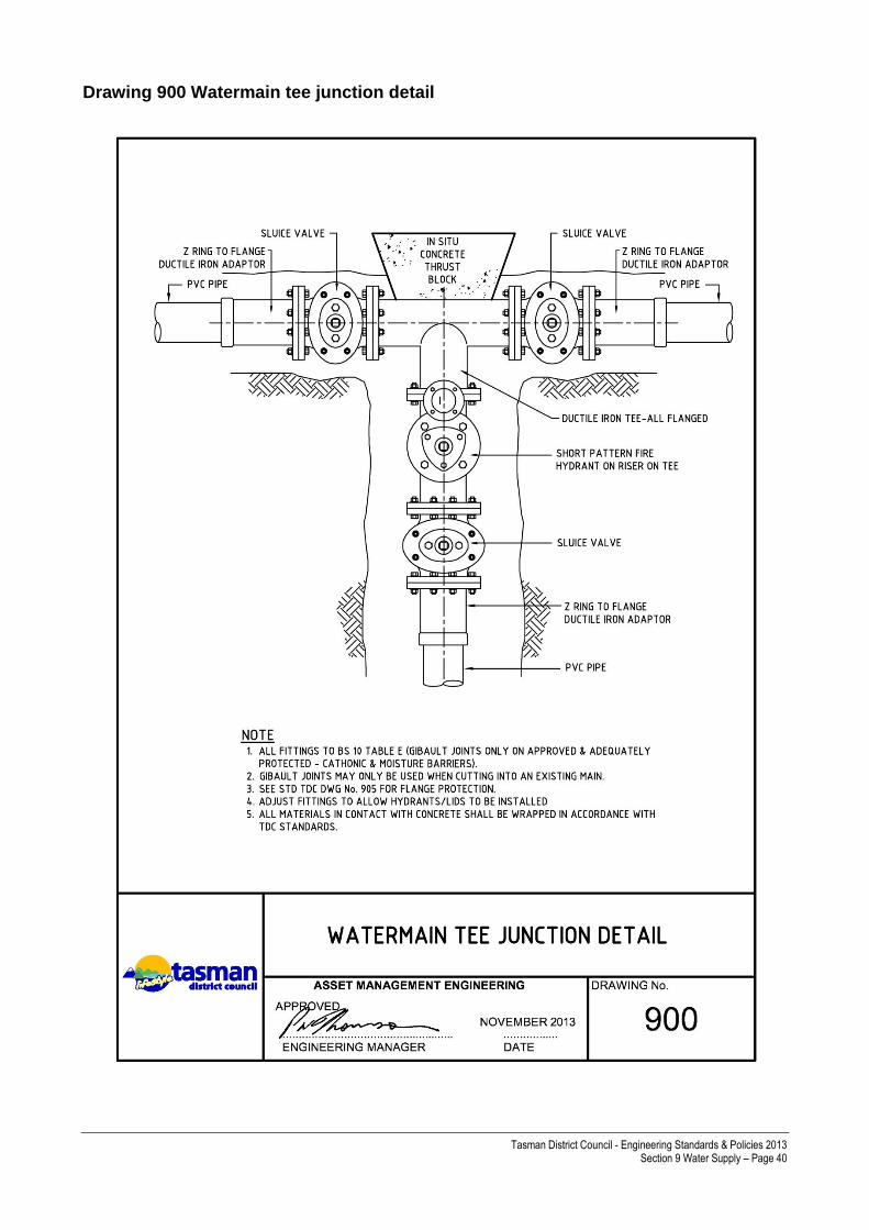
Tasman District Council - Engineering Standards & Policies 2013 Section 9 Water Supply – Page 40
Drawing 900 Watermain tee junction detail
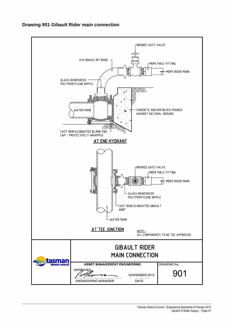
Tasman District Council - Engineering Standards & Policies 2013 Section 9 Water Supply – Page 41
Drawing 901 Gibault Rider main connection

Tasman District Council - Engineering Standards & Policies 2013 Section 9 Water Supply – Page 42
Drawing 902 Sluice valve key cap extension

Tasman District Council - Engineering Standards & Policies 2013 Section 9 Water Supply – Page 43
Drawing 903 Fire hydrant installation Z ring jointed

Tasman District Council - Engineering Standards & Policies 2013 Section 9 Water Supply – Page 44
Drawing 904 Sluice valve installation

Tasman District Council - Engineering Standards & Policies 2013 Section 9 Water Supply – Page 45
Drawing 905 Corrosion protection for flanges

Tasman District Council - Engineering Standards & Policies 2013 Section 9 Water Supply – Page 46
Drawing 906 Corrosion protection for unrestrained mechanical couplings

Tasman District Council - Engineering Standards & Policies 2013 Section 9 Water Supply – Page 47
Drawing 907 Standard valve & hydrant road markings

Tasman District Council - Engineering Standards & Policies 2013 Section 9 Water Supply – Page 48
Drawing 908 Water trenching requirement
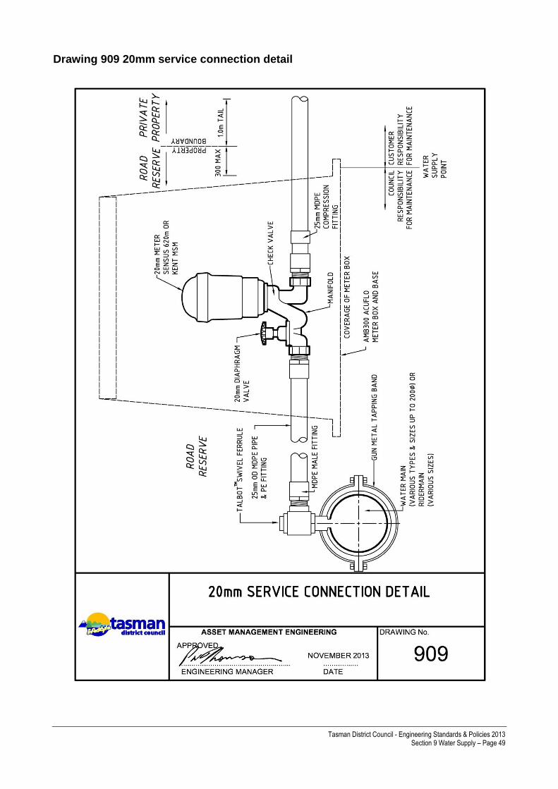
Tasman District Council - Engineering Standards & Policies 2013 Section 9 Water Supply – Page 49
Drawing 909 20mm service connection detail
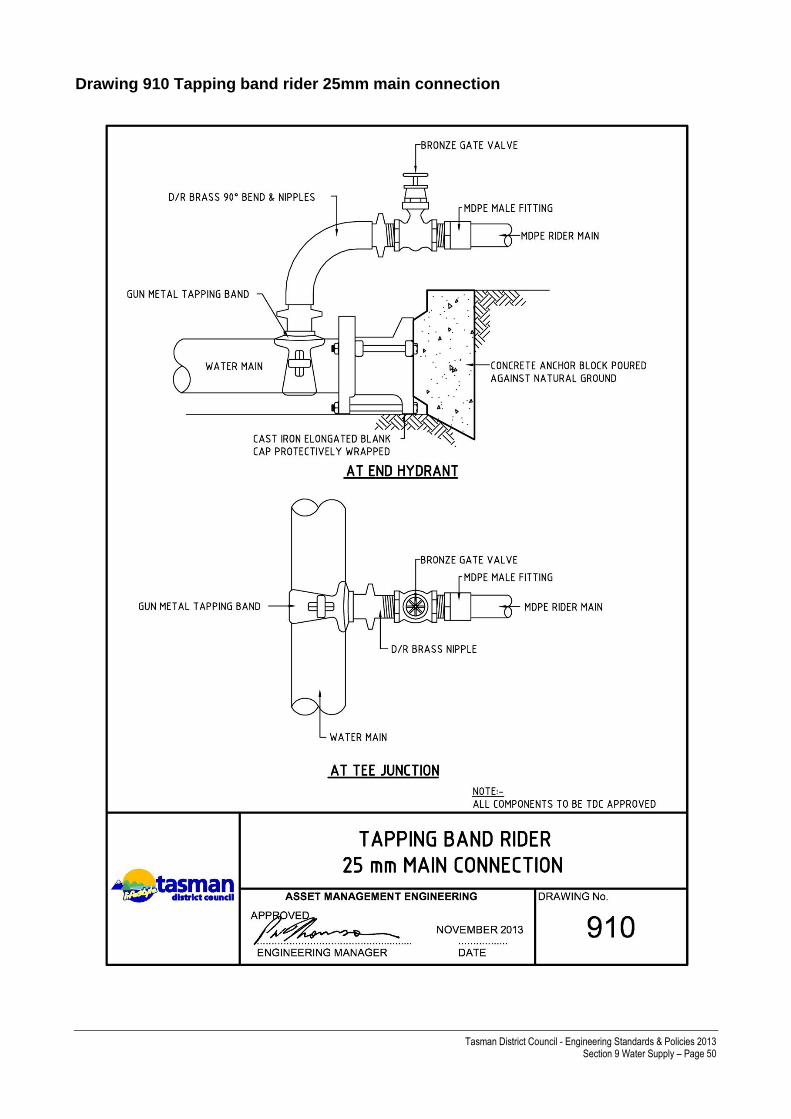
Tasman District Council - Engineering Standards & Policies 2013 Section 9 Water Supply – Page 50
Drawing 910 Tapping band rider 25mm main connection

Tasman District Council - Engineering Standards & Policies 2013 Section 9 Water Supply – Page 51
Drawing 911 Water connection policy – subdivision, cross lease & ROW