WATER SUPPLY CODE OF AUSTRALIA AGENCY … Dual Water Supply Systems While desirable, ... Water...
12
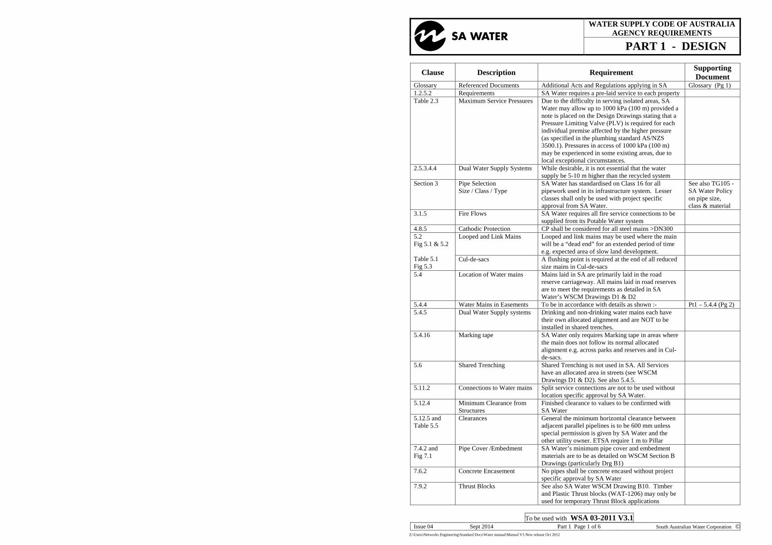
WATER SUPPLY CODE OF AUSTRALIA AGENCY REQUIREMENTS PART 1 - DESIGN Clause Description Requirement Supporting Document Glossary Referenced Documents Additional Acts and Regulations applying in SA Glossary (Pg 1) 1.2.5.2 Requirements SA Water requires a pre-laid service to each property Table 2.3 Maximum Service Pressures Due to the difficulty in serving isolated areas, SA Water may allow up to 1000 kPa (100 m) provided a note is placed on the Design Drawings stating that a Pressure Limiting Valve (PLV) is required for each individual premise affected by the higher pressure (as specified in the plumbing standard AS/NZS 3500.1). Pressures in access of 1000 kPa (100 m) may be experienced in some existing areas, due to local exceptional circumstances. 2.5.3.4.4 Dual Water Supply Systems While desirable, it is not essential that the water supply be 5-10 m higher than the recycled system Section 3 Pipe Selection Size / Class / Type SA Water has standardised on Class 16 for all pipework used in its infrastructure system. Lesser classes shall only be used with project specific approval from SA Water. See also TG105 - SA Water Policy on pipe size, class & material 3.1.5 Fire Flows SA Water requires all fire service connections to be supplied from its Potable Water system 4.8.5 Cathodic Protection CP shall be considered for all steel mains >DN300 5.2 Fig 5.1 & 5.2 Table 5.1 Fig 5.3 Looped and Link Mains Looped and link mains may be used where the main will be a “dead end” for an extended period of time e.g. expected area of slow land development. Cul-de-sacs A flushing point is required at the end of all reduced size mains in Cul-de-sacs 5.4 Location of Water mains Mains laid in SA are primarily laid in the road reserve carriageway. All mains laid in road reserves are to meet the requirements as detailed in SA Water’s WSCM Drawings D1 & D2 5.4.4 Water Mains in Easements To be in accordance with details as shown :- Pt1 – 5.4.4 (Pg 2) 5.4.5 Dual Water Supply systems Drinking and non-drinking water mains each have their own allocated alignment and are NOT to be installed in shared trenches. 5.4.16 Marking tape SA Water only requires Marking tape in areas where the main does not follow its normal allocated alignment e.g. across parks and reserves and in Cul- de-sacs. 5.6 Shared Trenching Shared Trenching is not used in SA. All Services have an allocated area in streets (see WSCM Drawings D1 & D2). See also 5.4.5. 5.11.2 Connections to Water mains Split service connections are not to be used without location specific approval by SA Water. 5.12.4 Minimum Clearance from Structures Finished clearance to values to be confirmed with SA Water 5.12.5 and Table 5.5 Clearances General the minimum horizontal clearance between adjacent parallel pipelines is to be 600 mm unless special permission is given by SA Water and the other utility owner. ETSA require 1 m to Pillar 7.4.2 and Fig 7.1 Pipe Cover /Embedment SA Water’s minimum pipe cover and embedment materials are to be as detailed on WSCM Section B Drawings (particularly Drg B1) 7.6.2 Concrete Encasement No pipes shall be concrete encased without project specific approval by SA Water 7.9.2 Thrust Blocks See also SA Water WSCM Drawing B10. Timber and Plastic Thrust blocks (WAT-1206) may only be used for temporary Thrust Block applications To be used with WSA 03-2011 V3.1 Issue 04 Sept 2014 Part 1 Page 1 of 6 South Australian Water Corporation © Z:\Users\Networks Engineering\Standard Docs\Water manual\Manual V3 New release Oct 2012
Transcript of WATER SUPPLY CODE OF AUSTRALIA AGENCY … Dual Water Supply Systems While desirable, ... Water...
WATER SUPPLY CODE OF AUSTRALIA AGENCY REQUIREMENTS
PART 1 - DESIGN
Clause Description Requirement Supporting Document
Glossary Referenced Documents Additional Acts and Regulations applying in SA Glossary (Pg 1) 1.2.5.2 Requirements SA Water requires a pre-laid service to each property Table 2.3 Maximum Service Pressures Due to the difficulty in serving isolated areas, SA
Water may allow up to 1000 kPa (100 m) provided a note is placed on the Design Drawings stating that a Pressure Limiting Valve (PLV) is required for each individual premise affected by the higher pressure (as specified in the plumbing standard AS/NZS 3500.1). Pressures in access of 1000 kPa (100 m) may be experienced in some existing areas, due to local exceptional circumstances.
2.5.3.4.4 Dual Water Supply Systems While desirable, it is not essential that the water supply be 5-10 m higher than the recycled system
Section 3 Pipe Selection Size / Class / Type
SA Water has standardised on Class 16 for all pipework used in its infrastructure system. Lesser classes shall only be used with project specific approval from SA Water.
See also TG105 - SA Water Policy on pipe size, class & material
3.1.5 Fire Flows SA Water requires all fire service connections to be supplied from its Potable Water system
4.8.5 Cathodic Protection CP shall be considered for all steel mains >DN300 5.2 Fig 5.1 & 5.2 Table 5.1 Fig 5.3
Looped and Link Mains Looped and link mains may be used where the main will be a “dead end” for an extended period of time e.g. expected area of slow land development.
Cul-de-sacs A flushing point is required at the end of all reduced size mains in Cul-de-sacs
5.4 Location of Water mains Mains laid in SA are primarily laid in the road reserve carriageway. All mains laid in road reserves are to meet the requirements as detailed in SA Water’s WSCM Drawings D1 & D2
5.4.4 Water Mains in Easements To be in accordance with details as shown :- Pt1 – 5.4.4 (Pg 2) 5.4.5 Dual Water Supply systems Drinking and non-drinking water mains each have
their own allocated alignment and are NOT to be installed in shared trenches.
5.4.16 Marking tape SA Water only requires Marking tape in areas where the main does not follow its normal allocated alignment e.g. across parks and reserves and in Cul-de-sacs.
5.6 Shared Trenching Shared Trenching is not used in SA. All Services have an allocated area in streets (see WSCM Drawings D1 & D2). See also 5.4.5.
5.11.2 Connections to Water mains Split service connections are not to be used without location specific approval by SA Water.
5.12.4 Minimum Clearance from Structures
Finished clearance to values to be confirmed with SA Water
5.12.5 and Table 5.5
Clearances General the minimum horizontal clearance between adjacent parallel pipelines is to be 600 mm unless special permission is given by SA Water and the other utility owner. ETSA require 1 m to Pillar
7.4.2 and Fig 7.1
Pipe Cover /Embedment SA Water’s minimum pipe cover and embedment materials are to be as detailed on WSCM Section B Drawings (particularly Drg B1)
7.6.2 Concrete Encasement No pipes shall be concrete encased without project specific approval by SA Water
7.9.2 Thrust Blocks See also SA Water WSCM Drawing B10. Timber and Plastic Thrust blocks (WAT-1206) may only be used for temporary Thrust Block applications
To be used with WSA 03-2011 V3.1 Issue 04 Sept 2014 Part 1 Page 1 of 6 South Australian Water Corporation ©
Z:\Users\Networks Engineering\Standard Docs\Water manual\Manual V3 New release Oct 2012

WATER SUPPLY CODE OF AUSTRALIA AGENCY REQUIREMENTS
PART 1 - DESIGN 7.9.3 Anchor Blocks All valves ≥DN100 are to be anchored in position.
See SA Water WSCM Drawing B8
7.10 Bulkheads and Trenchstops Use only on steep slopes where main passes through water body i.e. underground stream. SA Water concurrence required or may direct installation.
8.2 Stop Valves All Stop Valves shall be clockwise closing. Unless authorised otherwise all valves shall be flanged. Only Authorised valves shall be used.
8.2.2.2 Gate Valves Gate Valves shall be clockwise closing. Valves shall not be used for throttling flow
8.2.2.3 Butterfly valves On all butterfly valves ≤ DN300 the trunnions shall be vertical. For valves >DN300 SA Water is to be consulted as to the installation procedures and the position of trunnions
8.2.3 Stop valves in mains Stop valves are to be laid under the road pavement where applicable in the services in streets code. See WSCM Drg D1
8.2.6 Bypass of Stop Valves Minimum bypass size for water mains ≤ DN600 is DN80
Table 8.2 Stop Valve Spacing Criteria To be in accordance with details as shown: Pt1–Tbl 8.2 (Pg4) 8.2.7 Stop Valve - Location and
arrangements Stop Valves shall be located and arranged as specified in WSCM Drg Sections C & D
8.2.7.2 Fig 8.8
Branch Valve Adjacent to Main
See SA Water WSCM Drawings C5 – C8
8.2.7.3 Fig 8.9
Branch Valve Adjacent to Inner Splay Corner
See SA Water WSCM Drawings C5 – C8
8.2.7.4 Fig 8.10
Valve/hydrant combinations SA Water use the system shown in Figure 8.10(b)
8.8.4 Hydrants Types SA Water use the screw down hydrant (b). Pillar hydrants (c) may be specified for specific areas and need SA Water approval before installation
8.8.9 Hydrant Location SA Water’s preferred location for hydrants is directly above the main but when specified by SA Water it may be laid behind the curb
Pt1 –8.8.9 (Pg 4)
8.11 Location Marking See SA Water WSCM Drawings C17 and F6 9.2 Design Drawings Attached SA Water specific requirements apply Pt1–9.2 (Pg 5) Additional Requirements Annexures Annex A Typical SA Water Drawings Annex B Symbols and Abbreviations
To be used with WSA 03-2011 V3.1 Issue 04 Sept 2014 Part 1 Page 2 of 6 South Australian Water Corporation ©
Z:\Users\Networks Engineering\Standard Docs\Water manual\Manual V3 New release Oct 2012

Supplementary Documentation to WSA 03-2011 V3.1 Part 1
SA Water Supplementary Documentation Water Supply Code - Part 1 - Design
Related Requirements Pt 1 – 5.4.4 Water Mains in Easements
All Water Supply easements shall be vested in the name of the South Australian Water Corporation.
Power, gas and telecommunications utilities are not permitted to share or co-locate within SA Water easements to facilitate their respective services. This is due to the OHS&W implications for SA Water’s maintenance and operational personnel, or personnel contracted by SA Water.
Location of Mains/Easements All water mains and valves shall normally be located in roadways in accordance with the requirements of SA Water’s Water Supply Construction Manual (WSCM) Drawings D1 and D2.
Where it is not practical to run the water mains in the roadway, (e.g. due to topographical or linking requirements), water mains may be located in easements taken specifically for that purpose.
Where a water main easement is shared with a stormwater pipeline, the Council/Developer shall obtain their own stormwater easement from the landowner. The stormwater easement may overlap either a portion or the whole width of the SA Water easement. Because of the potential for damage to buildings and property the water main should be located on the side of the easement away from any buildings.
SA Water has no obligation to share water main easements with Councils or any other authorities. SA Water takes no responsibility for the stormwater pipeline, other than any damage caused to the stormwater pipeline by SA Water personnel or personnel contracted by SA Water. Notes:
Where it is impossible to attain lateral clearances from trees, it may be practical to tunnel beneath (or alongside) the tree(s), provided the tree type and root growth will permit such action and provided the tunnelling will not affect or endanger the health OR stability of the tree(s).
Easement Widths and Clearances Because of the potential for damage if a water main bursts, the easement width and clearance requirements are considerably greater than those required for sewers. SA Water’s minimum requirements are as follows in table 1:-
To be used with WSA 03-2011 V3.1 Issue 04 Sept 2014 Part 1 Page 3 of 6 South Australian Water Corporation ©
Z:\Users\Networks Engineering\Standard Docs\Water manual\Manual V3 New release Oct 2012

Supplementary Documentation to WSA 03-2011 V3.1 Part 1
Water Main Diameter Easement Widths (mm)
Minimum Clearance (mm)
Structures Other Pipes DN63 to DN 150 7 000 4 000 1 200
DN200 to DN 375 10 000 5 000 1 500
Table 1 - Easement Widths and Clearances
Dual Water Supply Systems within Easements Where it is necessary for dual water supply (drinking and recycled) mains to share the same easement there shall be a minimum separation of 1.5 m between the mains.
Easements Obtained under Developer Contracts The Developer shall be responsible for all costs associated with the acquisition of water main easements that are required within the development.
Easements within the development shall be established on the basis of the Final Plan of the Development. The final plan shall be prepared and lodged with the Development Assessment Commission by the Licensed Surveyor engaged by the Developer.
Where easements external to the development are required, the Developer may acquire the easements independently or may request that SA Water compulsorily acquire the easements at the Developers cost.
Pt 1 – Table 8.2 Stop Valve Spacing Criteria
SA Water’s policy is for all valves used in the reticulation system to be placed in locations so that in the event of a shut-down, no more than 50 premises will be affected. Whilst this is not always possible, all greater values shown in WSA-03 Part 1 Table 8.2 should be considered the absolute maximum.
Pt 1 –8.8.9 Hydrant /Air Valve Location Hydrants (fireplugs) shall be located in the roadway directly above the main as shown in WSCM Drawings Section C. Where specified they can be located behind the kerb.
SA Water uses hydrants (fireplugs) as scours and air release appurtenances. Adjustment can be made within the normal minimum spacing requirements for hydrants to be placed at high and low points within the system. When hydrants are unsuitable for a particular application, air relief valves and/or scours are to be used at high and low points (respectively) on the main.
When hydrants are to be used for scouring and air relief purposes they are to be identified on the design Drawings as to their purpose by use of the symbol as detailed in Annex B (e.g. FPAV and FPSc)
To be used with WSA 03-2011 V3.1 Issue 04 Sept 2014 Part 1 Page 4 of 6 South Australian Water Corporation ©
Z:\Users\Networks Engineering\Standard Docs\Water manual\Manual V3 New release Oct 2012

Supplementary Documentation to WSA 03-2011 V3.1 Part 1 Pt 1 –9.2 Design Drawings General
Design Drawings shall be drawn in black ink on copies of A3 size SA Water Pre-Titled Sheets and be of such clarity as to permit microfilming, scanning, and reduction to A4 size. Typical Drawings are shown as Annex A and symbols to be used on the drawings shall be in accordance with Annex B.
Scale Drawings shall be at 1:1000 scale, except where enlargements are required for complex fixtures.
Drawing Items that shall be shown are:
• Suburb or Township Names • Street Names • Allotment Numbers to the Real Property Act. • Boundaries • New Water Mains • Existing Mains • Easements (including enlargement to show details if required)–see Annex A • Restrained Joint sections of pipe (e.g. Tyton-Lok) • Size and Type of Pipes • Hydrants (Fire Plugs) including alternate usage e.g. scour • Fire Plug Connectors (with Thrust Block) • Stop Valves and Reflux Valves • Tapers (change in main size) • Existing Meters, Pressure Reducing Valves or any other special fitting • New Fire Services (if required) • New Large Domestic Services (if required) • Obsolete/Lifted Mains • Cathodic Protection Test Points and Insulated Joints • Dogleg Details around Obstructions • North Point • Bar Scale • Title Block entries - Main Details, Certification, Suburb/Township, Council,
Water District, Design Plan Number, Contract Number, Map Reference and Docket Number.
As-Constructed Information
The drawings shall make space allowance for the addition of As-constructed information once the reticulation system has been installed. See Supporting Documentation to WSA-03 Part 3 – Construction.
To be used with WSA 03-2011 V3.1 Issue 04 Sept 2014 Part 1 Page 5 of 6 South Australian Water Corporation ©
Z:\Users\Networks Engineering\Standard Docs\Water manual\Manual V3 New release Oct 2012

Supplementary Documentation to WSA 03-2011 V3.1 Part 1 Annexures Annex A Typical SA Water Drawings Annex B Symbols and Abbreviations
To be used with WSA 03-2011 V3.1 Issue 04 Sept 2014 Part 1 Page 6 of 6 South Australian Water Corporation ©
Z:\Users\Networks Engineering\Standard Docs\Water manual\Manual V3 New release Oct 2012

Supplementary Documentation to WSA-03-2011 V3.1 Part 1 Annex A
TYPICAL SA WATER DESIGN DRAWING
To be used with WSA 03-2010 V3.1 Issue 04 Sept 2014 Part 1 Page A1 of 4 South Australian Water Corporation ©
Z:\Users\Networks Engineering\Standard Docs\Water manual\Manual V3 New release Oct 2012

Supplementary Documentation to WSA-03-2011 V3.1 Part 1 Annex A
TYPICAL SA WATER DESIGN DRAWING
To be used with WSA 03-2010 V3.1 Issue 04 Sept 2014 Part 1 Page A2 of 4 South Australian Water Corporation ©
Z:\Users\Networks Engineering\Standard Docs\Water manual\Manual V3 New release Oct 2012

Supplementary Documentation to WSA-03-2011 V3.1 Part 1 Annex A
TYPICAL SA WATER DESIGN DRAWING
To be used with WSA 03-2010 V3.1 Issue 04 Sept 2014 Part 1 Page A3 of 4 South Australian Water Corporation ©
Z:\Users\Networks Engineering\Standard Docs\Water manual\Manual V3 New release Oct 2012

Supplementary Documentation to WSA-03-2011 V3.1 Part 1 Annex A
10 m Easement Required marked ‘A’.
Subject to Survey. Vide SA Water 3030/10
(External to Land division) Right of Entry
Not Obtained 15/07/10
EXAMPLE
TYPICAL EASEMENT ENLARGEMENT DETAILS (for Drawings)
Example of Easement Internal to New Land Division Notes • Easement boundaries to be in bold lines, hatch easement in thin lines and mark it with the letter ‘A’. • Fix location of easement by showing offsets to the property boundaries and locate main in easement in a
similar manner. • If the exact location of easement is undecided insert “subject to survey”. Example of Easement
External to Land
Division
Note:
• Easement to be shown as for Internal Easement (see above) with the addition of the docket number dealing with the easement acquisition (obtain from SA Water) and whether rights have been obtained and the date.
To be used with WSA 03-2010 V3.1 Issue 04 Sept 2014 Part 1 Page A4 of 4 South Australian Water Corporation ©
Z:\Users\Networks Engineering\Standard Docs\Water manual\Manual V3 New release Oct 2012

Supplementary Documentation to WSA-03-2011 V3.1 Part 1 Annex B
SYMBOLS AND ABBREVIATIONS FOR DRAWINGS AND AS-CONSTRUCTED AMENDMENTS
ITEM SYMBOL TEXT SIZE
Air Valve AV 4mm
Bend and angle of deflection x°y′ Bend
Boundary Cock BC
Branch or Tee Br or Tee
Branch with Scour Valve Sc 4mm
Branch with Stop Valve SV 4mm
Bypass BP
Cathodic Protection Rectifier CPR
Cathodic Protection Test Point CPTP 4mm
Change of Type
Change of Size - in line - at junction
x dia/y dia Taper x dia/y dia Taper
4mm 4mm
Connection 0.50mm
Connection Nipple CN
Cross Over
Fire Plug FP 4mm
Fire Plug Air Valve FPAV 4mm
Fire Plug Scour FP Sc 4mm
Fire Plug Connector (with thrust block) FP Con 4mm
Locked Stop Valve LSV 4mm
Main Cock MC
Meter Meter
Pillar Hydrant PH 4mm
Pressure Reducing Valve PRV 4mm
Reflux Valve RV 4mm
Stop Valve SV 4mm
Flushing Point FP 4mm
Water Main - new - existing
- lifted/abandoned
1.00mm 0.35mm 0.35mm
To be used with WSA 03-2010 V3.1 Issue 04 1 Dec 2012 Part 1 Page B1 of 2 South Australian Water Corporation ©
Z:\Users\Networks Engineering\Standard Docs\Water manual\Manual V3 New release Oct 2012

Supplementary Documentation to WSA-03-2011 V3.1 Part 1 Annex B
Water Main - material type :- Ductile Iron Concrete Lined Ductile Iron Concrete Lined with
Restraining Ring (Tyon) Jointing PolyEthylene Mild Steel Concrete Lined PolyVinyl Chloride
DICL DCTJ PE MSCL PVC
To be used with WSA 03-2010 V3.1 Issue 04 1 Dec 2012 Part 1 Page B2 of 2 South Australian Water Corporation ©
Z:\Users\Networks Engineering\Standard Docs\Water manual\Manual V3 New release Oct 2012