8146 5 V37 SafetySwitches EK00 III en - R. STAHL · > Clear assignment – safe technology – easy...
21
E7 E7 E7 E7 E7 E7 E7 E7 E7 E7 E7 E7 E7 E7 Series 8146/5-V37 and Series 8150/5-V37 www.stahl.de Load Disconnect Switches and Motor Starters E7/1 2017-06-26·EK00·III·en 2017-06-26·EK00·III·en Series 8146/5-V37 and Series 8150/5-V37 E7 14365E00 WebCode 8146L > Clear assignment – safe technology – easy installation > Intelligent structure – only one rotary actuator for frequency-controlled drives – ) 20 ms leading auxiliary contact for safe motor disconnection > Forced opening of the main contacts (load break switch) > Can be locked with 3 padlocks in 0-position > High corrosion resistance of the outer components > Version according to IEC/EN 62626-1 class 1 Safety switches ensure that the machines and installations are inevitably disconnected from the energy supply during cleaning and repair work. The usual preparatory work that may only be carried out by qualified electricians can be omitted. The safety switches can be used with both conventional drives and drives controlled by frequency converters. In addition to use with conventional drives, the safety switches are also suitable for use with drives controlled by frequency converters. When doing so, ensure that an auxiliary contact with these functions (NO: ON delayed; OFF leading) is used. The required time parameters must also be checked. The area of application lies in the frequency range from 5 to 400 Hz; the rated operating current must be adjusted accordingly. ATEX / IECEx NEC 505 NEC 506 NEC 500 Class I Class I Class II Class III Zone 0 1 2 20 21 22 Zone 0 1 2 20 21 22 Division 1 2 1 2 1 2 For use in x x x x For use in x For use in x
-
Upload
phungthien -
Category
Documents
-
view
216 -
download
1
Transcript of 8146 5 V37 SafetySwitches EK00 III en - R. STAHL · > Clear assignment – safe technology – easy...
E7
E7
E7
E7
E7
E7
E7
E7
E7
E7
E7
E7
E7
E7
Series 8146/5-V37 and Series 8150/5-V37
ww
w.s
tah
l.d
e
Load Disconnect Switches and Motor Starters E7/12017-06-26·EK00·III·en
2017-06-26·EK00·III·enSeries 8146/5-V37 and Series 8150/5-V37 E7
14365E00
WebCode 8146L
> Clear assignment– safe technology– easy installation
> Intelligent structure– only one rotary actuator
for frequency-controlled drives– ) 20 ms leading auxiliary
contact for safe motor disconnection
> Forced opening of the main contacts (load break switch)
> Can be locked with 3 padlocks in 0-position
> High corrosion resistance of the outer components
> Version according to IEC/EN 62626-1 class 1
Safety switches ensure that the machines and installations are inevitably disconnected from the energy supply during cleaning and repair work. The usual preparatory work that may only be carried out by qualified electricians can be omitted. The safety switches can be used with both conventional drives and drives controlled by frequency converters. In addition to use with conventional drives, the safety switches are also suitable for use with drives controlled by frequency converters. When doing so, ensure that an auxiliary contact with these functions (NO: ON delayed; OFF leading) is used. The required time parameters must also be checked. The area of application lies in the frequency range from 5 to 400 Hz; the rated operating current must be adjusted accordingly.
ATEX / IECEx NEC 505 NEC 506 NEC 500
Class I Class I Class II Class III
Zone 0 1 2 20 21 22 Zone 0 1 2 20 21 22 Division 1 2 1 2 1 2
For use in x x x x For use in x For use in x

Series 8146/5-V37 and Series 8150/5-V37
Load Disconnect Switches and Motor Starters 2017-06-26·EK00·III·enE7/2
Explosion Protection
Global (IECEx)Gas and dust 8146/5: IECEx PTB 06.0090, 8150/5: IECEx PTB 09.0049
8146/5: Ex db eb [ia Ga] [ib] mb q IIA, IIB, IIC T6, T5, T4 Gb8150/5: Ex db eb [ia Ga] [ib] mb q IIA, IIB, IIC T6, T5, T4 Gb8146/5: Ex tb IIIA, IIIB, IIIC T80 °C, T95 °C, T130 °C Db8150/5: Ex tb IIIC T80 °C, T95 °C, T130 °C Db
Europe (ATEX)Gas and dust 8146/5: PTB 01 ATEX 1024, 8150/5: PTB 09 ATEX 1109
8146/5: E II 2(1) G Ex db eb ia ib [ia Ga] mb q IIA, IIB, IIC T6, T5, T4 Gb8150/5: E II 2(1) G Ex db eb ia/ib [ia Ga] mb q IIA, IIB, IIC T6, T5, T4 Gb8146/5: E II 2 D Ex tb IIIA, IIIB, IIIC T80 °C, T95 °C, T130 °C Db 8150/5: E II 2 D Ex tb IIIC T80 °C, T95 °C, T130 °C Db(marking on rating plate is possible)
Certifications and certificatesCertificates IECEx, ATEX, Kazakhstan (TR), Russia (TR), Belarus (TR)
Further parametersFurther information see respective certifcate and operating instructions
Selection Table
Version Enclosure material
Equipment Cable dia. range [mm]
Switch Order number Weight
Colour Additional device
kg
10 A, 3-pole Polyester resin
black handle, black protective collar
– – 2 x 7 to 17 (M25), 1 x 4 to 13 (M20)
1 NO (ON delayed - OFF leading)
8146/5-V37-300-50-0050 1.700
Polyester resin
red handle, yellow protective collar
– – 2 x 7 to 17 (M25), 1 x 4 to 13 (M20)
1 NO (ON delayed - OFF leading)
8146/5-V37-300-50-1050 1.700
Technical Data
Design 10 AMechanical data
Degree of protection IP66 acc. to IEC/EN 60529Enclosure cover V37: In switching position ON removable, in OFF position lockedHandle Can be locked with 3 padlocks in 0-position
Montage / InstallationCable entries Standard: In polyamide, Series 8161
Special: In metalMain contacts
Electrical dataRated operational voltage 690 V ACRated insulation voltage 750 V Rated impulse withstand voltage
6 kV
Rated operational current 10 ASwitching capacity acc. to IEC/EN 60947-3; DIN VDE 0660, part 107
AC-3Ue I P 230 V ~400 V ~440 V ~500 V ~690 V ~
10 A10 A10 A10 A10 A
2.2 kW4.0 kW4.0 kW5.5 kW7.5 kW
DC-1 DC-13 (L/R = 300 ms)Ue I Ue I220 V 6 A3) 230 V 0.4 A 1) 1 conducting path
2) 2 conducting paths in series3) 3 conducting paths in series110 V 6 A2)
60 V 6 A1)
24 V 10 A1)

E7
E7
E7
E7
E7
E7
E7
E7
E7
E7
E7
E7
E7
E7
Series 8146/5-V37 and Series 8150/5-V37
Load Disconnect Switches and Motor Starters E7/32017-06-26·EK00·III·en
1) Engineering note:The maximum conductor cross-sections given were determined using the H07V. The minimum bending radius was assumed to be 4 x outer diameter in accordance with VDE 0298-3.2) only with heat-resistant cable > 70 °C on cable entries or/and > 85 °C on clamping pointsGrease: specified on rating plate
Service life of electrical / mechanical parts
30,000 operations
Max. short-circuit protection
16 A, tripping characteristic: gG acc. to IEC/EN 60291-1
Auxiliary contactsElectrical data
Rated operating voltage 400 V ACRated operational current 6 A
Mechanical dataSwitch 1 NO (ON delayed - OFF advanced)
Montage / InstallationTerminals 1.5 / 1.5 ... 2.5 / 4 mm2 finely stranded / solid wire
Ambient condition
Type8146/5-V..-
No. of poles max. current [A] Conductor cross-section 1) [mm2] Temperature class / Perm. ambient temperatureMain contacts Auxiliary
contactsmin. max.
300-...* 3 1 10 2.5 4 T6: -40 to +51 °CT6: -40 to +54 °C 2)
T5: -40 to +69 °C 2)
*When using a conductor cross-section of min. 2.5 mm2, the temperature class and ambient temperature are reduced to T4: -40 ... + 40 °C
Selection Table
Version Enclosure material
Equipment Cable dia. range [mm]
Switch Order number Weight
Colour Additional device
kg
12 / 16 A, 3-pole Polyester resin
black handle, black protective collar
– – 2 x 7 to 17 (M25), 1 x 4 to 13 (M20)
1 NO (ON delayed - OFF leading)
8146/5-V37-301-50-0050 0.962
Polyester resin
black handle, black protective collar
with N-terminal
2 x 7 to 17 (M25), 1 x 4 to 13 (M20)
1 NO (ON delayed - OFF leading)
8146/5-V37-301-50-0150 0.982
Polyester resin
red handle, yellow protective collar
– – 2 x 7 to 17 (M25), 1 x 4 to 13 (M20)
1 NO (ON delayed - OFF leading)
8146/5-V37-301-50-1050 0.958
Polyester resin
red handle, yellow protective collar
with N-terminal
2 x 7 to 17 (M25), 1 x 4 to 13 (M20)
1 NO (ON delayed - OFF leading)
8146/5-V37-301-50-1150 0.978
Technical Data
Design 12 / 16 AMechanical data
Degree of protection IP66 acc. to IEC/EN 60529Enclosure cover V37: In switching position ON removable, in OFF position lockedHandle Can be locked with 3 padlocks in 0-position
Montage / InstallationCable entries Standard: In polyamide, Series 8161
Special: In metalMain contacts
Electrical dataRated operational voltage 690 V ACRated insulation voltage 750 V Rated impulse withstand voltage
6 kV
Rated operational current 12 / 16 A
Technical Data

Series 8146/5-V37 and Series 8150/5-V37
Load Disconnect Switches and Motor Starters 2017-06-26·EK00·III·enE7/4
1) Engineering note:The maximum conductor cross-sections given were determined using the H07V. The minimum bending radius was assumed to be 4 x outer diameter in accordance with VDE 0298-3.2) only with heat-resistant cable > 70 °C on cable entries or/and > 85 °C on clamping pointsGrease: specified on rating plate
Switching capacity acc. to IEC/EN 60947-3; DIN VDE 0660, part 107
Service life of electrical / mechanical parts
30.000 operations
Max. short-circuit protection
25 A (Ie = 16 A); 16 A (Ie = 12 A), tripping characteristic: gG acc. to IEC/EN 60291-1
Auxiliary contactsElectrical data
Rated operating voltage 400 V ACRated operational current 6 A
Mechanical dataSwitch 1 NO (ON delayed - OFF advanced)
Montage / InstallationTerminals 1.5 / 1.5 ... 2.5 / 4 mm2 finely stranded / solid wire
Ambient condition
Type 8146/5-V..-
No. of poles max. current [A] Conductor cross-section 1) [mm2] Temperature class / Perm. ambient temperature
Main contacts Auxiliary contacts
min. max.
301-...* 3 1 12 / 16 2.5 4 T6: -40 to +51 °CT6: -40 to +54 °C 2)
T5: -40 to +69 °C 2)
*When using a conductor cross-section of min. 2.5 mm2, the temperature class and ambient temperature are reduced to T4: -40 ... + 40 °C
Technical Data
AC-3 AC-3Ue I P I P 230 V ~400 V ~440 V ~500 V ~690 V ~
12 A12 A12 A12 A12 A
3.0 kW5.5 kW5.5 kW7.5 kW7.5 kW
16 A16 A16 A16 A16 A
4.0 kW7.5 kW7.5 kW7.5 kW11.0 kW
DC-1 DC-13 (L/R = 300 ms)Ue I Ue I220 V 6 A3) 230 V 0.4 A 1) 1 conducting path
2) 2 conducting paths in series3) 3 conducting paths in series110 V 6 A2)
60 V 6 A1)
24 V 10 A1)

E7
E7
E7
E7
E7
E7
E7
E7
E7
E7
E7
E7
E7
E7
Series 8146/5-V37 and Series 8150/5-V37
Load Disconnect Switches and Motor Starters E7/52017-06-26·EK00·III·en
Selection Table
Version Enclosure material
Equipment Cable dia. range [mm]
Switch Order number Weight
Colour Additional device
kg
16 A, 3-pole stainless steel 1.4404
black handle, black protective collar
– – 2 x 7 to 17 (M25), 1 x 4 to 13 (M20)
1 NO (ON delayed - OFF leading)
8150/5-V37-302-50-0010 3.250
stainless steel 1.4404
red handle, yellow protective collar
– – 2 x 7 to 17 (M25), 1 x 4 to 13 (M20)
1 NO (ON delayed - OFF leading)
8150/5-V37-302-50-1010 3.250
Polyester resin
black handle, black protective collar
– – 2 x 7 to 17 (M25), 1 x 4 to 13 (M20)
1 NO (ON delayed - OFF leading)
8146/5-V37-302-50-0050 1.590
Polyester resin
black handle, black protective collar
with brass plate
for 2 x M25, 1 x M20
1 NO (ON delayed - OFF leading)
8146/5-V37-302-50-0040 1.530
Polyester resin
red handle, yellow protective collar
– – 2 x 7 to 17 (M25), 1 x 4 to 13 (M20)
1 NO (ON delayed - OFF leading)
8146/5-V37-302-50-1050 1.590
Polyester resin
red handle, yellow protective collar
with N-terminal
2 x 7 to 17 (M25), 1 x 4 to 13 (M20)
1 NO (ON delayed - OFF leading)
8146/5-V37-302-50-1150 1.590
16 A, 6-pole Polyester resin
red handle, yellow protective collar
– – 4 x 7 to 17 (M25), 1 x 4 to 13 (M20)
2 NO (1 x ON de-layed - OFF eading)
8146/5-V37-602-60-1010 2.640
Polyester resin
black handle, black protective collar
– – 4 x 7 to 17 (M25), 1 x 4 to 13 (M20)
2 NO (1 x ON de-layed - OFF leading)
8146/5-V37-602-60-0010 2.640
Technical Data
Design 16 AMechanical data
Degree of protection IP66 acc. to IEC/EN 60529Enclosure cover V37: In switching position ON removable, in OFF position lockedHandle Can be locked with 3 padlocks in 0-position
Montage / InstallationCable entries Standard: In polyamide, Series 8161
Special: In metalMain contacts
Electrical dataRated operational voltage 690 V ACRated insulation voltage 690 V Rated impulse withstand voltage
6 kV
Rated operational current 16 A

Series 8146/5-V37 and Series 8150/5-V37
Load Disconnect Switches and Motor Starters 2017-06-26·EK00·III·enE7/6
1) Engineering note:The maximum conductor cross-sections given were determined using the H07V. The minimum bending radius was assumed to be 4 x outer diameter in accordance with VDE 0298-3.2) only with heat-resistant cable > 70 °C on cable entries or/and > 85 °C on clamping pointsGrease: specified on rating plate
Switching capacity acc. to IEC/EN 60947-3; DIN VDE 0660, part 107
Service life of electrical / mechanical parts
30.000 operations
Max. short-circuit protection
25 A, tripping characteristic: gG acc. to IEC/EN 60291-1
Auxiliary contactsElectrical data
Rated operating voltage 400 V ACRated operational current 10 A
Mechanical dataSwitch 3-pole: 1 NO (ON delayed - OFF advanced)
6-pole: 2 NO (1 x ON delayed - OFF advanced / 1 x switching normally)Montage / Installation
Terminals 1.5 ... 6 mm2 finely stranded / solid
Ambient condition
Type 8146/5-V..-
No. of poles max. current [A] Conductor cross-section 1) [mm2] Temperature class / Perm. ambient temperature
Main contacts Auxiliary contacts
min. max.
302-...* 3 1 16 2.5 6 T6: -40 to +51 °CT6: -40 to +54 °C 2)
T5: -40 to +69 °C 2)
302-...-.5* 3 0 16 2.5 10 T4: -40 to +60 °C
602-...* 6 2 16 2.5 6 T6: -40 to +47 °CT5: -40 to +62 °C 2)
*When using a conductor cross-section of min. 2.5 mm2, the temperature class and ambient temperature are reduced to T4: -40 ... + 40 °C
Type 8150/5-V..-
302-... 3 1 16 2.5 6 T6: -40 to +50 °CT6: -40 to +65 °C 2)
Technical Data
AC-3Ue I P 230 V ~400 V ~440 V ~500 V ~690 V ~
16 A16 A16 A16 A16 A
4.0 kW7.5 kW7.5 kW7.5 kW11.0 kW
DC-1, DC-23 DC-13 (L/R = 300 ms)Ue I Ue I220 V 16 A3) 250 V 1.1 A 1) 1 conducting path
2) 2 conducting paths in series3) 3 conducting paths in series120 V 16 A2) 125 V 2.2 A
60 V 16 A1) 60 V 5.0 A
E7
E7
E7
E7
E7
E7
E7
E7
E7
E7
E7
E7
E7
E7
Series 8146/5-V37 and Series 8150/5-V37
Load Disconnect Switches and Motor Starters E7/72017-06-26·EK00·III·en
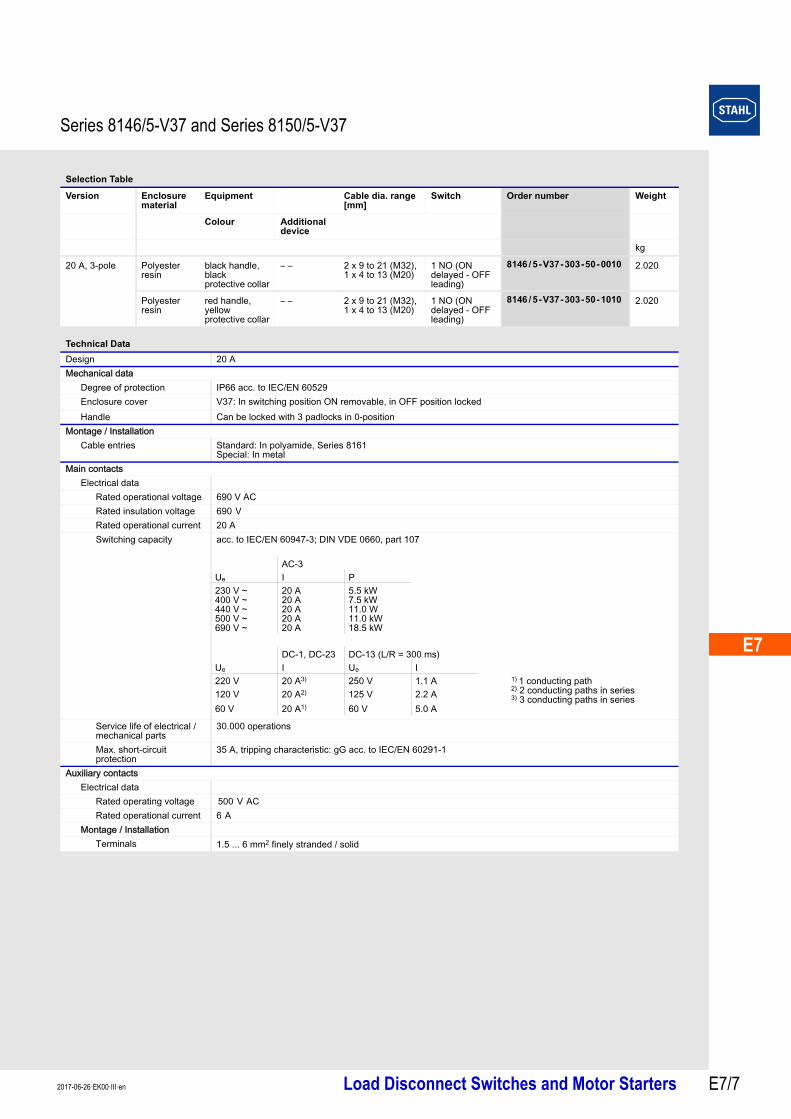
Selection Table
Version Enclosure material
Equipment Cable dia. range [mm]
Switch Order number Weight
Colour Additional device
kg
20 A, 3-pole Polyester resin
black handle, black protective collar
– – 2 x 9 to 21 (M32), 1 x 4 to 13 (M20)
1 NO (ON delayed - OFF leading)
8146/5-V37-303-50-0010 2.020
Polyester resin
red handle, yellow protective collar
– – 2 x 9 to 21 (M32), 1 x 4 to 13 (M20)
1 NO (ON delayed - OFF leading)
8146/5-V37-303-50-1010 2.020
Technical Data
Design 20 AMechanical data
Degree of protection IP66 acc. to IEC/EN 60529Enclosure cover V37: In switching position ON removable, in OFF position locked
Handle Can be locked with 3 padlocks in 0-positionMontage / Installation
Cable entries Standard: In polyamide, Series 8161Special: In metal
Main contactsElectrical data
Rated operational voltage 690 V ACRated insulation voltage 690 V Rated operational current 20 ASwitching capacity acc. to IEC/EN 60947-3; DIN VDE 0660, part 107
Service life of electrical / mechanical parts
30.000 operations
Max. short-circuit protection
35 A, tripping characteristic: gG acc. to IEC/EN 60291-1
Auxiliary contactsElectrical data
Rated operating voltage 500 V ACRated operational current 6 A
Montage / InstallationTerminals 1.5 ... 6 mm2 finely stranded / solid
AC-3Ue I P 230 V ~400 V ~440 V ~500 V ~690 V ~
20 A20 A20 A20 A20 A
5.5 kW7.5 kW11.0 W11.0 kW18.5 kW
DC-1, DC-23 DC-13 (L/R = 300 ms)Ue I Ue I220 V 20 A3) 250 V 1.1 A 1) 1 conducting path
2) 2 conducting paths in series3) 3 conducting paths in series120 V 20 A2) 125 V 2.2 A
60 V 20 A1) 60 V 5.0 A

Series 8146/5-V37 and Series 8150/5-V37
Load Disconnect Switches and Motor Starters 2017-06-26·EK00·III·enE7/8
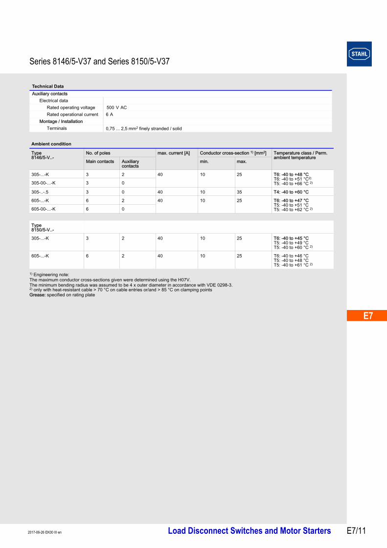
1) Engineering note:The maximum conductor cross-sections given were determined using the H07V. The minimum bending radius was assumed to be 4 x outer diameter in accordance with VDE 0298-3.2) only with heat-resistant cable > 70 °C on cable entries or/and > 85 °C on clamping pointsGrease: specified on rating plate
Ambient condition
Type 8146/5-V..-
No. of poles max. current [A] Conductor cross-section 1) [mm2] Temperature class / Perm. ambient temperature
Main contacts Auxiliary contacts
min. max.
303-...* 3 1 20 4 6 T6: -40 to +40 °CT5: -40 to +55 °C 2)
603-...* 6 2 20 4 6 T6: -40 to +41 °CT5: -40 to +56 °C 2)
6 2 20 6 6 T6: -40 to +42 °CT5: -40 to +50 °CT5: -40 to +57 °C 2)
6 0 20 4 6 T6: -40 to +46 °CT5: -40 to +61 °C 2)
T5: -40 to +52 °C
6 0 20 6 6 T5: -40 to +52 °C 2)
T5: -40 to +48 °C*When using a conductor cross-section of min. 2.5 mm2, the temperature class and ambient temperature are reduced to T4: -40 ... + 40 °C
Type 8150/5-V..-
303-... 3 1 20 4 6 T6: -40 to +42 °CT5: -40 to +57 °C 2)
3 1 20 6 6 T6: -40 to +43 °CT5: -40 to +58 °C 2)
T5: -40 to +53 °C
Selection Table
Version Enclosure material
Equipment Cable dia. range [mm]
Switch Order number Weight
Colour Additional device
kg
25 A, 3-pole stainless steel 1.4404
black handle, black protective collar
– – 2 x 9 to 21 (M32), 1 x 4 to 13 (M20)
1 NO (ON delayed - OFF leading)
8150/5-V37-304-50-0010 3.300
stainless steel 1.4404
red handle, yellow protective collar
– – 2 x 9 to 21 (M32), 1 x 4 to 13 (M20)
1 NO (ON delayed - OFF leading)
8150/5-V37-304-50-1010 3.300
Polyester resin
black handle, black protective collar
– – 2 x 9 to 21 (M32), 1 x 4 to 13 (M20)
1 NO (ON delayed - OFF leading)
8146/5-V37-304-50-0010 1.960
Polyester resin
red handle, yellow protective collar
– – 2 x 9 to 21 (M32), 1 x 4 to 13 (M20)
1 NO (ON delayed - OFF leading)
8146/5-V37-304-50-1010 2.020
Polyester resin
red handle, yellow protective collar
with N-terminal
2 x 9 to 21 (M32), 1 x 4 to 13 (M20)
1 NO (ON delayed - OFF leading)
8146/5-V37-304-50-1110 2.020
25 A, 6-pole Polyester resin
black handle, black protective collar
– – 4 x 7 to 17 (M25), 1 x 4 to 13 (M20)
2 NO (1 x ON delayed - OFF leading)
8146/5-V37-604-60-0010 2.790
Polyester resin
red handle, yellow protective collar
– – 4 x 7 to 17 (M25), 1 x 4 to 13 (M20)
2 NO (1 x ON delayed - OFF leading)
8146/5-V37-604-60-1010 2.790

E7
E7
E7
E7
E7
E7
E7
E7
E7
E7
E7
E7
E7
E7
Series 8146/5-V37 and Series 8150/5-V37
Load Disconnect Switches and Motor Starters E7/92017-06-26·EK00·III·en
1) Engineering note:The maximum conductor cross-sections given were determined using the H07V. The minimum bending radius was assumed to be 4 x outer diameter in accordance with VDE 0298-3.2) only with heat-resistant cable > 70 °C on cable entries or/and > 85 °C on clamping pointsGrease: specified on rating plate
Technical Data
Design 25 AMechanical data
Degree of protection IP66 acc. to IEC/EN 60529Enclosure cover V37: In switching position ON removable, in OFF position lockedHandle Can be locked with 3 padlocks in 0-position
Montage / InstallationCable entries Standard: In polyamide, Series 8161
Special: In metalMain contacts
Electrical dataRated operational voltage 690 V ACRated insulation voltage 690 V Rated operational current 25 ASwitching capacity acc. to IEC/EN 60947-3; DIN VDE 0660, part 107
Service life of electrical / mechanical parts
30.000 operations
Max. short-circuit protection
35 A, tripping characteristic: gG acc. to IEC/EN 60291-1
Auxiliary contactsElectrical data
Rated operating voltage 500 V ACRated operational current 6 A
Montage / InstallationTerminals 1.5 ... 6 mm2 finely stranded / solid
Ambient condition
Type 8146/5-V..-
No. of poles max. current [A] Conductor cross-section 1) [mm2] Temperature class / Perm. ambient temperature
Main contacts Auxiliary contacts
min. max.
304-...* 3 1 25 4 6 T6: -40 to +40 °CT5: -40 to +55 °C 2)
604-... 6 2 25 4 6 T5: -40 to +49 °C 2)
6 2 25 6 6 T6: -40 to +42 °CT5: -40 to +50 °CT5: -40 to +57 °C 2)
6 0 25 4 6 T5: -40 to +45 °C
6 0 25 6 6 T5: -40 to +52 °C 2)
T5: -40 to +48 °C*When using a conductor cross-section of min. 2.5 mm2, the temperature class and ambient temperature are reduced to T4: -40 ... + 40 °C
Type 8150/5-V..-
304-... 3 1 25 4 6 T5: -40 to +50 °C 2)
3 1 25 6 6 T6: -40 to +43 °CT5: -40 to +58 °C 2)
T5: -40 to +53 °C
AC-3Ue I P 230 V ~400 V ~440 V ~500 V ~690 V ~
25 A25 A25 A25 A25 A
5.5 kW11.0 kW11.0 kW15.0 kW22.0 kW
DC-1, DC-23 DC-13 (L/R = 300 ms)Ue I Ue I220 V 25 A3) 250 V 1.1 A 1) 1 conducting path
2) 2 conducting paths in series3) 3 conducting paths in series120 V 25 A2) 125 V 2.2 A
60 V 25 A1) 60 V 5.0 A

Series 8146/5-V37 and Series 8150/5-V37
Load Disconnect Switches and Motor Starters 2017-06-26·EK00·III·enE7/10
Selection Table
Version Enclosure material
Equipment Cable dia. range [mm]
Switch Order number Weight
Colour Additional device
kg
40 A, 3-pole Polyester resin
black handle, black protective collar
– – 2 x 12 to 28 (M40), 1 x 4 to 13 (M20)
– – 8146/5-V37-305-00-0010-K 5.560
Polyester resin
black handle, black protective collar
– – 2 x 12 to 28 (M40), 1 x 4 to 13 (M20)
1 NO (1 x ON delayed - OFF leading), 1 NC
8146/5-V37-305-51-0010-K 5.560
Polyester resin
red handle, yellow protective collar
– – 2 x 12 to 28 (M40), 1 x 4 to 13 (M20)
1 NO (1 x ON delayed - OFF leading), 1 NC
8146/5-V37-305-51-1010-K 4.620
stainless steel 1.4404
black handle, black protective collar
– – 2 x 12 to 28 (M40), 1 x 4 to 13 (M20)
1 NO (1 x ON delayed - OFF leading), 1 NC
8150/5-V37-305-51-0010-K 8.360
stainless steel 1.4404
red handle, yellow protective collar
– – 2 x 12 to 28 (M40), 1 x 4 to 13 (M20)
1 NO (1 x ON delayed - OFF leading), 1 NC
8150/5-V37-305-51-1010-K 8.360
Polyester resin
red handle, yellow protective collar
with N-terminal
2 x 12 to 28 (M40), 1 x 4 to 13 (M20)
1 NO (1 x ON delayed - OFF leading), 1 NC
8146/5-V37-305-51-1110-K 18.500
Polyester resin
red handle, yellow protective collar
main contact on terminal
2 x 12 to 28 (M40), 1 x 4 to 13 (M20)
– – 8146/5-V37-305-00-1510 7.500
40 A, 6-pole Polyester resin
black handle, black protective collar
– – 4 x 12 to 28 (M40), 1 x 4 to 13 (M20)
– – 8146/5-V37-605-00-0010-K 10.960
Polyester resin
black handle, black protective collar
– – 4 x 12 to 28 (M40), 1 x 4 to 13 (M20)
1 NO (1 x ON delayed - OFF leading), 1 NC
8146/5-V37-605-51-0010-K 10.960
Polyester resin
red handle, yellow protective collar
– – 4 x 12 to 28 (M40), 1 x 4 to 13 (M20)
1 NO (1 x ON delayed - OFF leading), 1 NC
8146/5-V37-605-51-1010-K 10.960
Technical Data
Design 40 AMechanical data
Degree of protection IP66 acc. to IEC/EN 60529Enclosure cover V37: In switching position ON removable, in OFF position locked
Handle Can be locked with 3 padlocks in 0-positionMontage / Installation
Cable entries Standard: In polyamide, Series 8161Special: In metal
Main contactsElectrical data
Rated operational voltage 690 V ACRated insulation voltage 750 V Rated operational current 40 ASwitching capacity acc. to IEC/EN 60947-3; DIN VDE 0660, part 107
Service life of electrical / mechanical parts
30.000 operations
Max. short-circuit protection
80 A, tripping characteristic: gG acc. to IEC/EN 60291-1
AC-3Ue I P 240 V ~400 V ~440 V ~500 V ~690 V ~
40 A40 A40 A40 A40 A
11.0 kW22.0 kW22.0 kW22.0 kW37.0 kW
DC-23, DC-1Ue I220 V 40 A3) 1) 1 conducting path
2) 2 conducting paths in series3) 3 conducting paths in series120 V 40 A2)
60 V 40 A1)
E7
E7
E7
E7
E7
E7
E7
E7
E7
E7
E7
E7
E7
E7
Series 8146/5-V37 and Series 8150/5-V37
Load Disconnect Switches and Motor Starters E7/112017-06-26·EK00·III·en
1) Engineering note:The maximum conductor cross-sections given were determined using the H07V. The minimum bending radius was assumed to be 4 x outer diameter in accordance with VDE 0298-3.2) only with heat-resistant cable > 70 °C on cable entries or/and > 85 °C on clamping pointsGrease: specified on rating plate
Auxiliary contactsElectrical data
Rated operating voltage 500 V ACRated operational current 6 A
Montage / InstallationTerminals 0,75 ... 2,5 mm2 finely stranded / solid
Ambient condition
Type 8146/5-V..-
No. of poles max. current [A] Conductor cross-section 1) [mm2] Temperature class / Perm. ambient temperature
Main contacts Auxiliary contacts
min. max.
305-...-K 3 2 40 10 25 T6: -40 to +48 °CT6: -40 to +51 °C2)
T5: -40 to +66 °C 2)305-00-...-K 3 0
305-..-.5 3 0 40 10 35 T4: -40 to +60 °C
605-...-K 6 2 40 10 25 T6: -40 to +47 °CT5: -40 to +51 °CT5: -40 to +62 °C 2)605-00-...-K 6 0
Type 8150/5-V..-
305-...-K 3 2 40 10 25 T6: -40 to +45 °CT5: -40 to +49 °CT5: -40 to +60 °C 2)
605-...-K 6 2 40 10 25 T6: -40 to +46 °CT5: -40 to +48 °CT5: -40 to +61 °C 2)
Technical Data

Series 8146/5-V37 and Series 8150/5-V37
Load Disconnect Switches and Motor Starters 2017-06-26·EK00·III·enE7/12
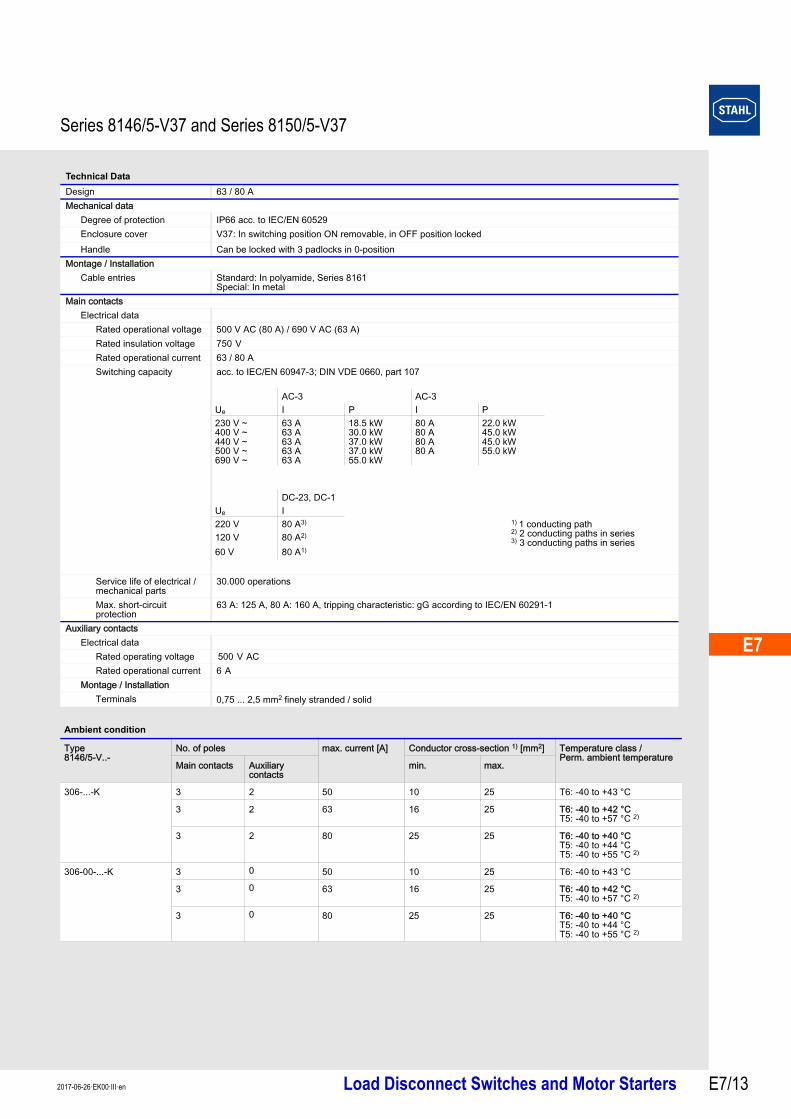
Selection Table
Version Enclosure material
Equipment Cable dia. range [mm]
Switch Order number Weight
Colour Additional device
kg
63 / 80 A, 3-pole
Polyester resin
black handle, black protective collar
– – 2 x 16 to 35 (M50), 1 x 4 to 13 (M20)
– – 8146/5-V37-306-00-0010 8.060
Polyester resin
black handle, black protective collar
– – 2 x 16 to 35 (M50), 1 x 4 to 13 (M20)
1 NO (1 x ON delayed - OFF leading), 1 NC
8146/5-V37-306-51-0010 7.960
Polyester resin
black handle, black protective collar
with brass plate
2 x 16 to 35 (M50), 1 x 4 to 13 (M20)
1 NO (1 x ON delayed - OFF leading), 1 NC
8146/5-V37-306-51-0040 11.800
Polyester resin
red handle, yellow protective collar
– – 2 x 16 to 35 (M50), 1 x 4 to 13 (M20)
1 NO (1 x ON delayed - OFF leading), 1 NC
8146/5-V37-306-51-1010 7.550
Polyester resin
red handle, yellow protective collar
with N-terminal
2 x 16 to 35 (M50), 1 x 4 to 13 (M20)
1 NO (1 x ON delayed - OFF leading), 1 NC
8146/5-V37-306-51-1110 7.550
stainless steel 1.4404
black handle, black protective collar
– – 2 x 16 to 35 (M50), 1 x 4 to 13 (M20)
1 NO (1 x ON delayed - OFF leading), 1 NC
8150/5-V37-306-51-0010-K 12.600
stainless steel 1.4404
red handle, yellow protective collar
– – 2 x 16 to 35 (M50), 1 x 4 to 13 (M20)
1 NO (1 x ON delayed - OFF leading), 1 NC
8150/5-V37-306-51-1010-K 12.600
Polyester resin
red handle, yellow protective collar
main contact on terminal
2 x 16 to 35 (M50), 1 x 4 to 13 (M20)
– – 8146/5-V37-306-00-1510 10.700
63 / 80 A, 3-pole, compact *)
Polyester resin
black handle, black protective collar
– – 2 x 16 to 35 (M50), 1 x 4 to 13 (M20)
– – 8146/5-V37-306-00-0010-K 5.680
Polyester resin
black handle, black protective collar
– – 2 x 16 to 35 (M50), 1 x 4 to 13 (M20)
1 NO (1 x ON delayed - OFF leading), 1 NC
8146/5-V37-306-51-0010-K 5.680
Polyester resin
red handle, yellow protecti-ve collar
– – 2 x 16 to 35 (M50), 1 x 4 to 13 (M20)
1 NO (1 x ON delayed - OFF leading), 1 NC
8146/5-V37-306-51-1010-K 5.680
Polyester resin
red handle, yellow protective collar
with N-terminal
2 x 16 to 35 (M50), 1 x 4 to 13 (M20)
1 NO (1 x ON delayed - OFF leading), 1 NC
8146/5-V37-306-51-1110-K 5.680
63 / 80 A, 6-pole
Polyester resin
black handle, black protective collar
– – 4 x 16 to 35 (M50), 1 x 4 to 13 (M20)
– – 8146/5-V37-606-00-0010 10.100
Polyester resin
black handle, black protective collar
– – 4 x 16 to 35 (M50), 1 x 4 to 13 (M20)
1 NO (1 x ON delayed - OFF leading), 1 NC
8146/5-V37-606-51-0010 10.100
Polyester resin
red handle, yellow protective collar
– – 4 x 16 to 35 (M50), 1 x 4 to 13 (M20)
1 NO (1 x ON delayed - OFF leading), 1 NC
8146/5-V37-606-51-1010 10.100
Note *) “K“ versions with a smaller design size; see dimensional drawings
E7
E7
E7
E7
E7
E7
E7
E7
E7
E7
E7
E7
E7
E7
Series 8146/5-V37 and Series 8150/5-V37
Load Disconnect Switches and Motor Starters E7/132017-06-26·EK00·III·en
Technical Data
Design 63 / 80 AMechanical data
Degree of protection IP66 acc. to IEC/EN 60529Enclosure cover V37: In switching position ON removable, in OFF position locked
Handle Can be locked with 3 padlocks in 0-positionMontage / Installation
Cable entries Standard: In polyamide, Series 8161Special: In metal
Main contactsElectrical data
Rated operational voltage 500 V AC (80 A) / 690 V AC (63 A)Rated insulation voltage 750 V Rated operational current 63 / 80 ASwitching capacity acc. to IEC/EN 60947-3; DIN VDE 0660, part 107
Service life of electrical / mechanical parts
30.000 operations
Max. short-circuit protection
63 A: 125 A, 80 A: 160 A, tripping characteristic: gG according to IEC/EN 60291-1
Auxiliary contactsElectrical data
Rated operating voltage 500 V ACRated operational current 6 A
Montage / InstallationTerminals 0,75 ... 2,5 mm2 finely stranded / solid
Ambient condition
Type 8146/5-V..-
No. of poles max. current [A] Conductor cross-section 1) [mm2] Temperature class / Perm. ambient temperature
Main contacts Auxiliary contacts
min. max.
306-...-K 3 2 50 10 25 T6: -40 to +43 °C
3 2 63 16 25 T6: -40 to +42 °CT5: -40 to +57 °C 2)
3 2 80 25 25 T6: -40 to +40 °CT5: -40 to +44 °CT5: -40 to +55 °C 2)
306-00-...-K 3 0 50 10 25 T6: -40 to +43 °C
3 0 63 16 25 T6: -40 to +42 °CT5: -40 to +57 °C 2)
3 0 80 25 25 T6: -40 to +40 °CT5: -40 to +44 °CT5: -40 to +55 °C 2)
AC-3 AC-3Ue I P I P 230 V ~400 V ~440 V ~500 V ~690 V ~
63 A63 A63 A63 A63 A
18.5 kW30.0 kW37.0 kW37.0 kW55.0 kW
80 A80 A80 A80 A
22.0 kW45.0 kW45.0 kW55.0 kW
DC-23, DC-1Ue I220 V 80 A3) 1) 1 conducting path
2) 2 conducting paths in series3) 3 conducting paths in series120 V 80 A2)
60 V 80 A1)
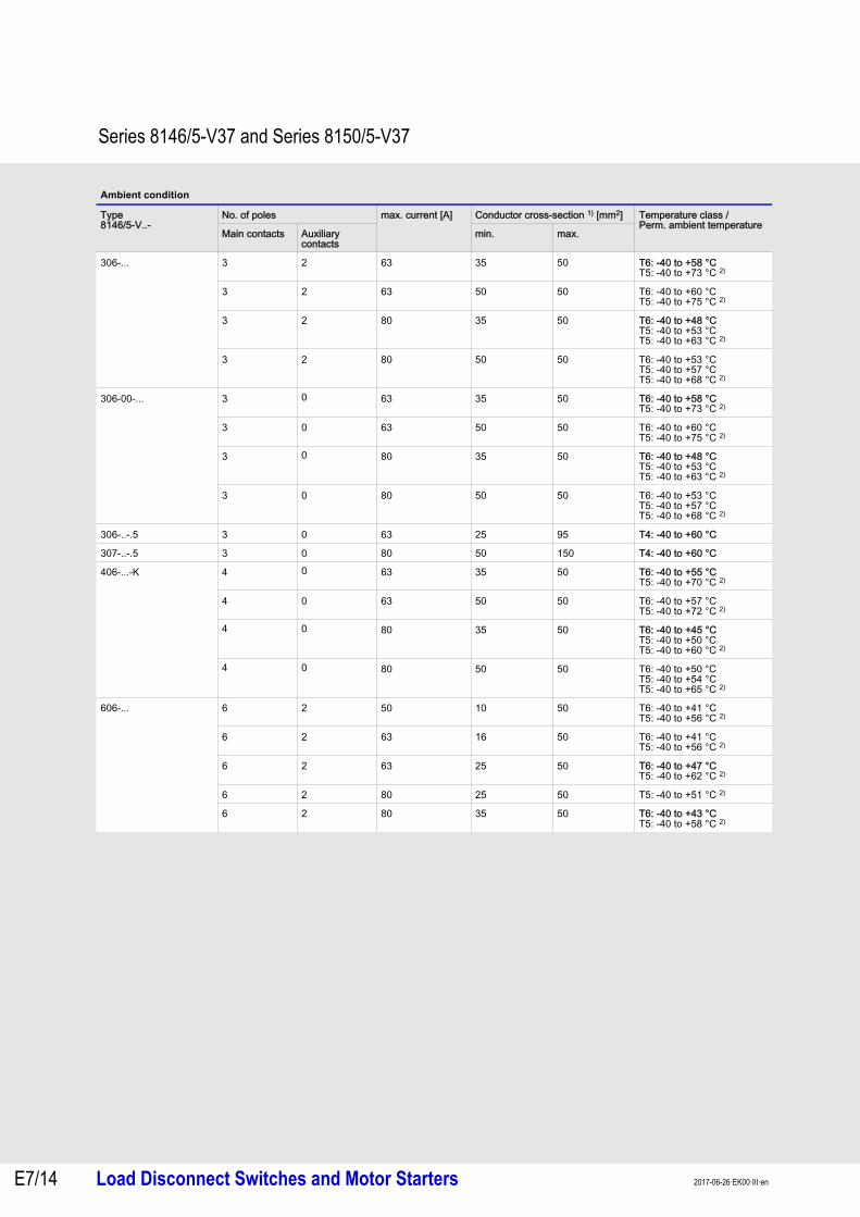
Series 8146/5-V37 and Series 8150/5-V37
Load Disconnect Switches and Motor Starters 2017-06-26·EK00·III·enE7/14
306-... 3 2 63 35 50 T6: -40 to +58 °CT5: -40 to +73 °C 2)
3 2 63 50 50 T6: -40 to +60 °CT5: -40 to +75 °C 2)
3 2 80 35 50 T6: -40 to +48 °CT5: -40 to +53 °CT5: -40 to +63 °C 2)
3 2 80 50 50 T6: -40 to +53 °CT5: -40 to +57 °CT5: -40 to +68 °C 2)
306-00-... 3 0 63 35 50 T6: -40 to +58 °CT5: -40 to +73 °C 2)
3 0 63 50 50 T6: -40 to +60 °CT5: -40 to +75 °C 2)
3 0 80 35 50 T6: -40 to +48 °CT5: -40 to +53 °CT5: -40 to +63 °C 2)
3 0 80 50 50 T6: -40 to +53 °CT5: -40 to +57 °CT5: -40 to +68 °C 2)
306-..-.5 3 0 63 25 95 T4: -40 to +60 °C
307-..-.5 3 0 80 50 150 T4: -40 to +60 °C
406-...-K 4 0 63 35 50 T6: -40 to +55 °CT5: -40 to +70 °C 2)
4 0 63 50 50 T6: -40 to +57 °CT5: -40 to +72 °C 2)
4 0 80 35 50 T6: -40 to +45 °CT5: -40 to +50 °CT5: -40 to +60 °C 2)
4 0 80 50 50 T6: -40 to +50 °CT5: -40 to +54 °CT5: -40 to +65 °C 2)
606-... 6 2 50 10 50 T6: -40 to +41 °CT5: -40 to +56 °C 2)
6 2 63 16 50 T6: -40 to +41 °CT5: -40 to +56 °C 2)
6 2 63 25 50 T6: -40 to +47 °CT5: -40 to +62 °C 2)
6 2 80 25 50 T5: -40 to +51 °C 2)
6 2 80 35 50 T6: -40 to +43 °CT5: -40 to +58 °C 2)
Ambient condition
Type 8146/5-V..-
No. of poles max. current [A] Conductor cross-section 1) [mm2] Temperature class / Perm. ambient temperature
Main contacts Auxiliary contacts
min. max.

E7
E7
E7
E7
E7
E7
E7
E7
E7
E7
E7
E7
E7
E7
Series 8146/5-V37 and Series 8150/5-V37
Load Disconnect Switches and Motor Starters E7/152017-06-26·EK00·III·en
1) Engineering note:The maximum conductor cross-sections given were determined using the H07V. The minimum bending radius was assumed to be 4 x outer diameter in accordance with VDE 0298-3.2) only with heat-resistant cable > 70 °C on cable entries or/and > 85 °C on clamping pointsGrease: specified on rating plate
606-00-... 6 0 50 10 50 T6: -40 to +41 °CT5: -40 to +56 °C 2)
6 0 63 16 50 T6: -40 to +41 °CT5: -40 to +56 °C 2)
6 0 63 25 50 T6: -40 to +47 °CT5: -40 to +62 °C 2)
6 0 80 25 50 T5: -40 to +51 °C 2)
6 0 80 35 50 T6: -40 to +43 °CT5: -40 to +58 °C 2)
Type 8150/5-V..-
306-...-K 3 2 63 16 50 T5: -40 to +50 °C 2)
T5: -40 to +46 °C
3 2 63 25 50 T6: -40 to +42 °CT5: -40 to +51 °CT5: -40 to +57 °C 2)
3 2 80 25 50 T5: -40 to +47 °C 1)
T5: -40 to +43 °C
3 2 80 25 50 T6: -40 to +40 °CT5: -40 to +41 °CT5: -40 to +55 °C 1)
606-... 6 2 50 16 50 T6: -40 to +45 °CT5: -40 to +60 °C 2)
6 2 63 16 50 T5: -40 to +46 °C 2)
T5: -40 to +42 °C
6 2 63 25 50 T6: -40 to +43 °CT5: -40 to +47 °CT5: -40 to +58 °C 2)
6 2 80 25 50 T5: -40 to +41 °C
Ambient condition
Type 8146/5-V..-
No. of poles max. current [A] Conductor cross-section 1) [mm2] Temperature class / Perm. ambient temperature
Main contacts Auxiliary contacts
min. max.

Series 8146/5-V37 and Series 8150/5-V37
Load Disconnect Switches and Motor Starters 2017-06-26·EK00·III·enE7/16
Selection Table
Version Enclosure material
Equipment Cable dia. range [mm]
Switch Order number Weight
Colour Additional device
kg
125 / 160 A, 3-pole
Polyester resin
black handle, black protective collar
– – 2 x 28 to 48 M63, 1 x 4 to 13 M20
– – 8146/5-V37-308-00-0010 18.500
Polyester resin
black handle, black protective collar
– – 2 x 28 to 48 (M63), 1 x 4 to 13 (M20)
1 NO (1 x ON delayed - OFF leading), 1 NC
8146/5-V37-308-51-0010 18.500
Polyester resin
black handle, black protective collar
with brass plate
2 x 28 to 48 M63, 1 x 4 to 13 M20
1 NO (1 x ON delayed - OFF leading), 1 NC
8146/5-V37-308-51-0040 22.770
Polyester resin
red handle, yellow protective collar
– – 2 x 28 to 48 (M63), 1 x 4 to 13 (M20)
1 NO (1 x ON delayed - OFF leading), 1 NC
8146/5-V37-308-51-1010 18.500
Polyester resin
red handle, yellow protective collar
with N-terminal
2 x 28 to 48 (M63), 1 x 4 to 13 (M20)
1 NO (1 x ON delayed - OFF leading), 1 NC
8146/5-V37-308-51-1110 23.200
125 / 160 A, 3-pole, compact *)
Polyester resin
black handle, black protective collar
– – 2 x 28 to 48 (M63), 1 x 4 to 13 (M20)
– – 8146/5-V37-308-00-0010-K 14.350
Polyester resin
black handle, black protective collar
– – 2 x 28 to 48 (M63), 1 x 4 to 13 (M20)
1 NO (1 x ON delayed - OFF leading), 1 NC
8146/5-V37-308-51-0010-K 14.350
stainless steel 1.4404
black handle, black protective collar
– – 2 x 28 to 48 M63, 1 x 4 to 13 M20
2 NO (1 x ON delayed - OFF leading)
8150/5-V37-308-51-0010-K 25.625
Polyester resin
black handle, black protective collar
with brass plate
2 x 28 to 48 M63, 1 x 4 to 13 M20
1 NO (1 x ON delayed - OFF leading), 1 NC
8146/5-V37-308-51-0040-K 21.260
Polyester resin
red handle, yellow protective collar
– – 2 x 28 to 48 (M63), 1 x 4 to 13 (M20)
1 NO (1 x ON delayed - OFF leading), 1 NC
8146/5-V37-308-51-1010-K 14.350
stainless steel 1.4404
red handle, yellow protective collar
– – 2 x 28 to 48 M63, 1 x 4 to 13 M20
1 NO (1 x ON delayed - OFF leading), 1 NC
8150/5-V37-308-51-1010-K 25.625
Polyester resin
red handle, yellow protective collar
with N-terminal
2 x 28 to 48 (M63), 1 x 4 to 13 (M20)
1 NO (1 x ON delayed - OFF leading), 1 NC
8146/5-V37-308-51-1110-K 14.350
125 / 160 A, 6-pole
Polyester resin
black handle, black protective collar
– – 4 x 28 to 48 (M63), 1 x 4 to 13 (M20)
– – 8146/5-V37-608-00-0010 22.760
Polyester resin
black handle, black protective collar
– – 4 x 28 to 48 (M63), 1 x 4 to 13 (M20)
1 NO (1 x ON delayed - OFF leading), 1 NC
8146/5-V37-608-51-0010 22.760
Polyester resin
red handle, yellow protective collar
– – 4 x 28 to 48 (M63), 1 x 4 to 13 (M20)
1 NO (1 x ON delayed - OFF leading), 1 NC
8146/5-V37-608-51-1010 22.760
Polyester resin
red handle, yellow protective collar
with N-terminal
4 x 28 to 48 (M63), 1 x 4 to 13 (M20)
1 NO (1 x ON delayed - OFF leading), 1 NC
8146/5-V37-608-51-1110 22.760

E7
E7
E7
E7
E7
E7
E7
E7
E7
E7
E7
E7
E7
E7
Series 8146/5-V37 and Series 8150/5-V37
Load Disconnect Switches and Motor Starters E7/172017-06-26·EK00·III·en
180 A, 3-pole Polyester resin
black handle, black protective collar
– – 2 x 28 to 48 (M63), 1 x 4 to 13 (M20)
– – 8146/5-V37-310-00-0010 19.560
Polyester resin
black handle, black protective collar
– – 2 x 28 to 48 (M63), 1 x 4 to 13 (M20)
1 NO (1 x ON delayed - OFF leading), 1 NC
8146/5-V37-310-51-0010 19.560
Polyester resin
black handle, black protective collar
with brass plate
2 x 28 to 48 M63, 1 x 4 to 13 M20
1 NO (1 x ON delayed - OFF leading), 1 NC
8146/5-V37-310-51-0040 22.770
Polyester resin
red handle, yellow protective collar
– – 2 x 28 to 48 (M63), 1 x 4 to 13 (M20)
1 NO (1 x ON delayed - OFF leading), 1 NC
8146/5-V37-310-51-1010 19.560
Polyester resin
red handle, yellow protective collar
with N-terminal
2 x 28 to 48 (M63), 1 x 4 to 13 (M20)
1 NO (1 x ON delayed - OFF leading), 1 NC
8146/5-V37-310-51-1110 19.560
180 A, 3-pole, compact *)
Polyester resin
black handle, black protective collar
– – 2 x 28 to 48 (M63), 1 x 4 to 13 (M20)
– – 8146/5-V37-310-00-0010-K 14.360
Polyester resin
black handle, black protective collar
– – 2 x 28 to 48 (M63), 1 x 4 to 13 (M20)
1 NO (1 x ON delayed - OFF leading), 1 NC
8146/5-V37-310-51-0010-K 14.360
Polyester resin
black handle, black protective collar
with brass plate
2 x 28 to 48 M63, 1 x 4 to 13 M20
1 NO (1 x ON delayed - OFF leading), 1 NC
8146/5-V37-310-51-0040-K 15.140
Polyester resin
red handle, yellow protective collar
– – 2 x 28 to 48 (M63), 1 x 4 to 13 (M20)
1 NO (1 x ON delayed - OFF leading), 1 NC
8146/5-V37-310-51-1010-K 14.360
Polyester resin
red handle, yellow protective collar
with N-terminal
2 x 28 to 48 (M63), 1 x 4 to 13 (M20)
1 NO (1 x ON delayed - OFF leading), 1 NC
8146/5-V37-310-51-1110-K 14.360
180 A, 6-pole Polyester resin
black handle, black protective collar
– – 4 x 28 to 48 (M63), 1 x 4 to 13 (M20)
– – 8146/5-V37-610-00-0010 37.360
Polyester resin
black handle, black protective collar
– – 4 x 28 to 48 (M63), 1 x 4 to 13 (M20)
1 NO (1 x ON delayed - OFF leading), 1 NC
8146/5-V37-610-51-0010 37.360
Polyester resin
black handle, black protective collar
with brass plate
4 x 28 to 48 M63, 1 x 4 to 13 M20
1 NO (1 x ON delayed - OFF leading), 1 NC
8146/5-V37-610-51-0040
Polyester resin
red handle, yellow protective collar
– – 4 x 28 to 48 (M63), 1 x 4 to 13 (M20)
1 NO (1 x ON delayed - OFF leading), 1 NC
8146/5-V37-610-51-1010 37.360
Polyester resin
red handle, yellow protective collar
with N-terminal
4 x 28 to 48 (M63), 1 x 4 to 13 (M20)
1 NO (1 x ON delayed - OFF leading), 1 NC
8146/5-V37-610-51-1110 37.360
Note *) “K“ versions with a smaller design size; see dimensional drawings
Selection Table
Version Enclosure material
Equipment Cable dia. range [mm]
Switch Order number Weight
Colour Additional device
kg
Series 8146/5-V37 and Series 8150/5-V37
Load Disconnect Switches and Motor Starters 2017-06-26·EK00·III·enE7/18
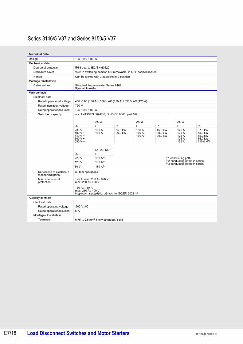
Technical Data
Design 125 / 160 / 180 AMechanical data
Degree of protection IP66 acc. to IEC/EN 60529Enclosure cover V37: In switching position ON removable, in OFF position locked
Handle Can be locked with 3 padlocks in 0-positionMontage / Installation
Cable entries Standard: In polyamide, Series 8161Special: In metal
Main contactsElectrical data
Rated operational voltage 400 V AC (180 A) / 500 V AC (150 A) / 690 V AC (125 A)Rated insulation voltage 750 V Rated operational current 125 / 160 / 180 ASwitching capacity acc. to IEC/EN 60947-3; DIN VDE 0660, part 107
Service life of electrical / mechanical parts
30.000 operations
Max. short-circuit protection
125 A: max. 200 A / 690 Vmax. 250 A / 500 V
160 A / 180 A:max. 250 A / 400 V tripping characteristic: gG acc. to IEC/EN 60291-1
Auxiliary contactsElectrical data
Rated operating voltage 500 V ACRated operational current 6 A
Montage / InstallationTerminals 0,75 ... 2,5 mm2 finely stranded / solid
AC-3 AC-3 AC-3Ue I P I P I P 230 V ~400 V ~440 V ~500 V ~690 V ~
180 A180 A
55.0 kW90.0 kW
160 A160 A160 A
45.0 kW90.0 kW90.0 kW
125 A125 A125 A125 A125 A
37.0 kW55.0 kW75.0 kW75.0 kW110.0 kW
DC-23, DC-1Ue I220 V 180 A3) 1) 1 conducting path
2) 2 conducting paths in series3) 3 conducting paths in series120 V 180 A2)
60 V 180 A1)

E7
E7
E7
E7
E7
E7
E7
E7
E7
E7
E7
E7
E7
E7
Series 8146/5-V37 and Series 8150/5-V37
Load Disconnect Switches and Motor Starters E7/192017-06-26·EK00·III·en
1) Engineering note:The maximum conductor cross-sections given were determined using the H07V. The minimum bending radius was assumed to be 4 x outer diameter in accordance with VDE 0298-3.2) only with heat-resistant cable > 70 °C on cable entries or/and > 85 °C on clamping pointsGrease: specified on rating plate
Ambient condition
Type 8146/5-V..-
No. of poles max. current [A] Conductor cross-section 1) [mm2] Temperature class / Perm. ambient temperature
Main contacts Auxiliary contacts
min. max.
308-...-K 3 1 125 95 120 T6: -40 to +46 °CT5: -40 to +62 °C 2)
T4: -40 to +72 °C 2)
3 1 125 120 120 T6: -40 to +50 °CT5: -40 to +65 °C 2)
T4: -40 to +72 °C 2)
308-... 3 1 125 95 150 T6: -40 to +47 °CT5: -40 to +62 °C 2)
T4: -40 to +72 °C 2)
608-... 6 2 125 95 150 T6: -40 to +40 °CT5: -40 to +55 °C 2)
T4: -40 to +72 °C 2)
Type 8150/5-V..-
308-...-K 3 1 125 95 120 T5: -40 to +50 °CT4: -40 to +63 °C 2)
3 1 125 120 120 T5: -40 to +44 °CT5: -40 to +59 °C 2)
T4: -40 to +68 °C 2)
Type 8146/5-V..-
308-...-K 3 1 160 95 120 T5: -40 to +40 °CT5: -40 to +50 °C 2)
T4: -40 to +55 °C 2)
3 1 160 120 120 T5: -40 to +45 °CT5: -40 to +49 °CT4: -40 to +60 °C 2)
308-... 3 1 160 95 150 T5: -40 to +40 °CT5: -40 to +47 °C 2)
T4: -40 to +55 °C 2)
3 1 160 120 150 T5: -40 to +45 °CT5: -40 to +51 °C 2)
T4: -40 to +60 °C 2)
608-... 6 2 160 95 150 T4: -40 to +40 °CT4: -40 to +55 °C 2)
6 2 160 120 150 T4: -40 to +45 °CT4: -40 to +55 °C 2)
Type 8150/5-V..-
308-...-K 3 1 160 95 120 T4: -40 to +44 °C 2)
3 1 160 120 120 T5: -40 to +41 °C 2)
T5: -40 to +51 °C 2)
Type 8146/5-V..-
310-...-K 3 1 180 95 120 T4: -40 to +40 °C 2)
3 1 180 120 120 T4: -40 to +50 °C 2)
310-... 3 1 180 95 150 T4: -40 to +40 °C 2)
3 1 180 120 150 T4: -40 to +50 °C 2)
610-... 6 2 180 120 150 T4: -40 to +50 °C 2)

Series 8146/5-V37 and Series 8150/5-V37
Load Disconnect Switches and Motor Starters 2017-06-26·EK00·III·enE7/20
Circuit diagrams
Dimensional Drawings (All dimensions in mm) – Subject to alterations
04120E00
Enclosure and sealing material
Type 8146/5-V.. 8150/5-V..
Enclosure Polyester resin, glass-fibre-reinforced, dark-grey, similar to RAL 7024Impact resistance ) 7 Jsurface resistance ( 109 Ωflame retardant acc. IEC/EN 60695, UL 94, ASTM D635
stainless steel 1.4404 (AISI 316L), brush finished
Seal silocone, foamed, optional EPDM silicone, foamed
15622E00 15581E00
-V..-6..-60-..6-pin + 1 NO (1x ON delayed - OFF leading / 1 x switching normally)
-V..-3..-00-..3-pin
15579E00
-V..-6..-00-..6-pin
A
B C
Dimensions [mm]A B C
3-pin 10, 12 / 16 A 8146/5-V37-300-50-...8146/5-V37-301-50-...
112.5112.5
112.5112.5
131131
16 A 8146/5-V37-302-50-...8146/5-V37-302-..-.5..8150/5-V37-302-50-...8146/5-V37-302-50-0250
170340.5176.5227
112.5170176.5112.5
132132132172
20 A 8146/5-V37-303-50-... 170 170 13225 A 8146/5-V37-304-50-...
8150/5-V37-304-50-...170176.5
170176.5
132132
40 A 8146/5-V37-305-....-K8146/5-V37-305-..-.5..8150/5-V37-305-...-K
340.5340.5360
170340.5176.5
176.5195194
63 / 80 A 8146/5-V37-306-...-K8146/5-V37-306-...8146/5-V37-306-..-.5..8150/5-V37-306-S1-...
340.5340.5681.5360
170340.5340.5360
195195195196
80 A 8146/5-V37-307-..-.5.. 681.5 340.5 195125 / 160 A 8146/5-V37-308-..-K
8146/5-V37-308-...681.5681.5
340.5681.5
205205
180 A 8146/5-V37-310-..-K8146/5-V37-310-...
681.5681.5
340.5681.5
205205
6-pin 16 A 8146/5-V37-602-60-... 170 170 17225 A 8146/5-V37-604-60-... 227 170 17240 A 8146/5-V37-605-....-K 340.5 340.5 20563 / 80 A 8146/5-V37-606-... 681.5 340.5 205125 / 160 A 8146/5-V37-608-... 1,023 681.5 243180 A 8146/5-V37-610-... 1,023 681.5 243
0° 90°
8642 0210
013 5 7 91 13
14
23
24
0° 90°
642
31 5
0° 90°
8642 0210
013 5 7 91
E7
E7
E7
E7
E7
E7
E7
E7
E7
E7
E7
E7
E7
E7
Series 8146/5-V37 and Series 8150/5-V37
Load Disconnect Switches and Motor Starters E7/212017-06-26·EK00·III·en
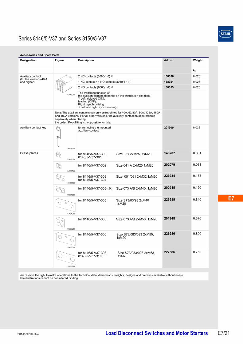
Accessories and Spare Parts
Designation Figure Description Art. no. Weight
kg
Auxiliary contact (for the versions 40 A and higher)
12446E00
2 NC contacts (8080/1-3) 2) 168356 0.026
1 NC contact + 1 NO contact (8080/1-1) 1) 168351 0.026
2 NO contacts (8080/1-4) 2) 168353 0.026
The switching function of the auxiliary contact depends on the installation slot used.1) Left: delayed (ON), leading (OFF);Right: synchronising2) Left and right: synchronising
Note: The auxiliary contacts can only be retrofitted for 40A, 63/80A, 80A, 125A, 160A and 180A versions. For all other versions, the auxiliary contact must be ordered separately when placing the order. Retrofitting is not possible for this.
Auxiliary contact key
14151E00
for removing the mounted auxiliary contact
201909 0.035
Brass plates
17483E00
148207 0.081
04902E00
202079 0.081
17481E00
226934 0.155
07097E00
200215 0.190
17484E00
226935 0.840
07098E00
201948 0.370
17486E00
226936 0.800
17485E00
227586 0.750
We reserve the right to make alterations to the technical data, dimensions, weights, designs and products available without notice. The illustrations cannot be considered binding.
for 8146/5-V37-300, 8146/5-V37-301
Size 031 2xM25, 1xM20
for 8146/5-V37-302 Size 041 A 2xM25 1xM20
for 8146/5-V37-303for 8146/5-V37-304
Size. 051/061 2xM32 1xM20
for 8146/5-V37-305-..K Size 073 A/B 2xM40, 1xM20
for 8146/5-V37-305 Size S73/83/93 2xM40 1xM20
for 8146/5-V37-306 Size 073 A/B 2xM50, 1xM20
for 8146/5-V37-306 Size S73/083/093 2xM50, 1xM20
for 8146/5-V37-308, 8146/5-V37-310
Size S73/083/093 2xM63, 1xM20