Automatic Sliding door Installation Manual for: CSL400 Standard...
44
Automatic Sliding door Q1.0 - 2011 Installation Manual for: CSL400 Standard CSL400 ER for Escape Routes
-
Upload
trinhtuyen -
Category
Documents
-
view
219 -
download
1
Transcript of Automatic Sliding door Installation Manual for: CSL400 Standard...
Automatic Sliding door
Q1.0 - 2011
Installation Manual for:CSL400 Standard
CSL400 ER for Escape Routes

Automatic Sliding door Installation Manual

Automatic Sliding door Installation Manual
Introduction 3
All users and owners of the sliding door must read, understand and obey the information and instructions in this manual. Failure to do so may result in damage to, or failure of the equipment, and possible injury to persons.
This manual contains functional descriptions and installation information for a sliding door. When information or instructions are applicable to all the methods of operation or models, there are no operation types or model numbers in the title. When information or instructions are applicable to specific methods of operation or models, the applicable operation type or model numbers appear in the title.
About this Manual

Automatic Sliding door Installation Manual
4
Contents About this Manual ..................................................................................................... 3
1. Introduction. ...................................................................................................... 6
1.1 CSL movement properties ..................................................................................................................................... 7 1.1.1 Priorities for escape routes .................................................................................................................. 7 1.1.2 Priority for none escape routes ........................................................................................................... 8 1.1.3 General, Symbols .................................................................................................................................. 9
2. Safety instructions ........................................................................................... 10
2.1 General ................................................................................................................................................................. 10 2.2 General requirements for safety and accident prevention ............................................................................... 10 2.3 Use for the intended purpose ............................................................................................................................. 10 2.4 Sensors .................................................................................................................................................................. 11
3. Functional Descriptions ................................................................................... 12
3.1 Technical Data ...................................................................................................................................................... 13
4. Hazards and safety distances .......................................................................... 14
4.1 Examples of possible hazards on automatic sliding doors ................................................................................ 14 4.2 Hazards and protective measures ....................................................................................................................... 14
5. Installation ....................................................................................................... 17
Preparation .......................................................................................................................................................... 17 5.1 ...................................................................................................................................................................................... 17
5.1.1 Tools required .................................................................................................................................... 17 5.1.2 Personal protection ............................................................................................................................ 17
5.2 Before start of installation .................................................................................................................................. 18 5.3 Start of installation .............................................................................................................................................. 20
5.3.1 Mechanical installation ...................................................................................................................... 20 5.3.2 Installation drawing, hole distances and drilling of holes. ............................................................. 21 5.3.3 Complete sliding door drive unit with existing door leaves ........................................................... 22 5.3.4 Installation of the carry wheel assemblies ....................................................................................... 22 5.3.5 Installation of the door leaves .......................................................................................................... 22 5.3.6 Carry wheel alignment ...................................................................................................................... 24 5.3.7 Adjustment of door leaves. ............................................................................................................... 24 5.3.8 Installation of tooth belt ................................................................................................................... 25 5.3.9 Installation of the end stops ............................................................................................................. 26 5.3.10 Installation of the electro mechanical lock...................................................................................... 26 5.3.11 Installation of the mechanical lock .................................................................................................. 26 5.3.12 Connection of program selector ...................................................................................................... 27 5.3.13 Installation of the place holder of the header box ......................................................................... 27 5.3.14 Final mechanical testing ................................................................................................................... 28
6. Start-up ............................................................................................................ 29
6.1 Cable installation plan/ Wiring diagram ............................................................................................................ 29 6.2 Start-up ................................................................................................................................................................. 30
Automatic Sliding door Installation Manual
5
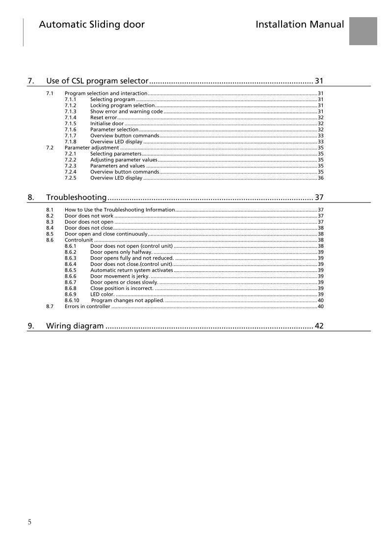
7. Use of CSL program selector ........................................................................... 31
7.1 Program selection and interaction ..................................................................................................................... 31 7.1.1 Selecting program ............................................................................................................................. 31 7.1.2 Locking program selection ................................................................................................................ 31 7.1.3 Show error and warning code .......................................................................................................... 31 7.1.4 Reset error .......................................................................................................................................... 32 7.1.5 Initialise door ..................................................................................................................................... 32 7.1.6 Parameter selection ........................................................................................................................... 32 7.1.7 Overview button commands ............................................................................................................. 33 7.1.8 Overview LED display ........................................................................................................................ 33
7.2 Parameter adjustment ........................................................................................................................................ 35 7.2.1 Selecting parameters ......................................................................................................................... 35 7.2.2 Adjusting parameter values .............................................................................................................. 35 7.2.3 Parameters and values ...................................................................................................................... 35 7.2.4 Overview button commands ............................................................................................................. 35 7.2.5 Overview LED display ........................................................................................................................ 36
8. Troubleshooting .............................................................................................. 37
8.1 How to Use the Troubleshooting Information .................................................................................................. 37 8.2 Door does not work ............................................................................................................................................ 37 8.3 Door does not open ............................................................................................................................................ 37 8.4 Door does not close ............................................................................................................................................. 38 8.5 Door open and close continuously ..................................................................................................................... 38 8.6 Controlunit .......................................................................................................................................................... 38
8.6.1 Door does not open (control unit) ................................................................................................... 38 8.6.2 Door opens only halfway. ................................................................................................................. 39 8.6.3 Door opens fully and not reduced. .................................................................................................. 39 8.6.4 Door does not close.(control unit). ................................................................................................... 39 8.6.5 Automatic return system activates ................................................................................................... 39 8.6.6 Door movement is jerky. ................................................................................................................... 39 8.6.7 Door opens or closes slowly. ............................................................................................................. 39 8.6.8 Close position is incorrect. ................................................................................................................ 39 8.6.9 LED color. ........................................................................................................................................... 39 8.6.10 Program changes not applied. ......................................................................................................... 40
8.7 Errors in controller .............................................................................................................................................. 40
9. Wiring diagram ............................................................................................... 42

6
The CSL400 sliding door drive unit is suitable for both standard doors, as well as for doors in escape routes.
The CSL-CU-400 is an advanced control unit for automatic sliding doors in accordance with DIN-18650, part 1+2, June 2010 and AutSchR for escape routes.
With its many inputs and wide output range for the motor, practically every sliding door can be controlled by the controller.
More advanced door movements and better control is possible with the encoder position feedback.
Parts required for operation are:
The controller; Motor with gear and encoder; Transformer or DC power supply; Sensors for opening the door; Safety sensors.
In addition, other parts can be connected for more control, easier connection, security and safety. These are:
PC/PDA GUI (Graphical User Interface) tool for status information, program selection and parameter setting;
Electromagnetic lock; Safety sensors; Battery for operation during power loss; Program selector
There are four sensors inputs: one sensor input for each side of the door and two safety sensor inputs.
Other inputs and outputs include:
One output with programmable function for indication of the door status; One porter switch which allows the door to be opened at all times; Six programmable inputs for functions such as: fire, robbery and disable motion, etc.; Interlock communication allowing only one door open at a time.
With the eight programs: close, one way full, automatic full, open full, one way reduced, automatic reduced, open reduced, and manual, the controller can be used in any situation.
Settings can be set for speed, acceleration, open times, safety, and many more options.
All the settings can be set in the normalised units: mm, seconds, mV, mA, etc.
The PC/PDA GUI software is used to set the parameters. The PC/PDA GUI software is also used to show the door status and warnings, select the program for operation, test the inputs and outputs, see the measured values up and down, load the parameter settings, and store.
1. Introduction

Automatic Sliding door Installation Manual
7
1.1 CSL movement properties
1.1.1 Priorities for escape routes
Table 1. Movement priorities for escape routes Priority State/event Position1 Moving Speed Sensitivity
Highest Service mode2 – Emergency open Full Fast Off Fire34 Full3 Fast Off Battery/power event35 Full3 Fast Obstruction Note6 Slow Lower Side screen7 Full Slow7 Inside AIR Full 8 Outside AIR Full 8 Program manual Manual Motor / encoder test – Find close position Closed Slow Special Porter Full Program close Closed Find open position Full Slow Special Redundant motor module error9 Full Program open Full Inside radar Full Fast Robbery Closed Program one-way –10 Ghost opening Full Lowest Outside radar Full 1. Target position for the door: F=Full, R=Reduced, M=Manual, C=Close. 2. “Service mode” can only be initiated from PC/PDA or pushbutton on the controller and is for servicing
purposes and therefore allowed in escape routes. 3. Action can be programmed, but program limitations apply and only open actions are allowed. 4. Fire opening not performed if program close and “fire action” is “Open of close” or “Close or automatic”. 5. Battery/power event not performed in programs close and manual. 6. Obstruction returns to the previous position or slowly continues to open. 7. Creep only allowed after the door is opened for 80%. 8. Only re-open a closing door. 9. For dual motor escape routes where one of the modules fails. 10. Program exit-only will only prevent the incoming events.
General notes for escape routes 1. The only allowed open position is full open. 2. Programs close and manual may not be selected via programmable inputs.

8
1.1.2 Priority for non-escape routes
Table 2. Movement priorities for non-escape routes Priority State/event Position1 Moving Speed Sensitivity
Highest Service mode2 – Disable motion – Stop Off Emergency open Full Fast Obstruction (see note) Prev5 Slow Lower Fire3
F / C / M6 7 Battery/power event4 F / M6 Side screen F / R Slow8 Inside AIR Prev9 Outside AIR Prev9 Program manual Manual Motor / encoder test – Find close position Closed Slow Special Porter Full Pharmacy Pharmacy Program close Closed Find open position Full Slow Special Program open F / R10 Interlock mode close Closed Inside radar F / R10 Robbery Closed Program one-way –11 Ghost opening Full Lowest Outside radar F / R10 1. Target position for the door: F=Full, R=Reduced, M=Manual, C=Close. 2. Service mode can only be initiated from PC/PDA or pushbutton on the controller and is for service
purposes and therefore allowed in escape routes. 3. Fire opening not performed if program close and “fire action” is “Open of close” or “Close or automatic”. 4. Battery/power event not performed in programs close and manual. 5. Obstruction returns to the previous position or slowly continues to open 6. Action can be programmed 7. If sensors are disabled during fire the door moves slowly 8. Slow speed position adjustable 9. The previous open position will be used 10. Full open has priority over reduced, depending on program and sensor demands. 11. Program exit-only will only prevent the incoming events. General notes for non escape routes 1. Opening is always to full after initialisation for the next 5 cycles. 2. Programs close and manual may be selected via programmable inputs.

Automatic Sliding door Installation Manual
9
General notes on all doors 1. After initialisation the next 5 cycles will have the sensitivity lowered and the current set to the maximum
motor current. 2. The close position must be known before any other movement can be performed. 3. Find open position is performed if the open position is not known and the door needs to open for events. 4. FullSens inputs are equal in priority as radars, but position is fixed to full open. 5. “Toggle” has the same priority as the inside radar. 6. Obstruction is not detected in the high priority events. The other events will cause the obstruction to fully
return to the previous position, which could mean that the door will close fully before opening again. The second time the door moves will be at a normal speed up to 100mm before the obstruction position, after which the low speed is used.
1.1.3 General, Symbols
The CSL400 drive unit has been developed and produced with state of the art technology and in accordance with the valid regulations regarding, e.g., force and speed limitations. Unintended use can cause danger for the user.
Installation, maintenance and operation of the CSL400 drive unit are only allowed by qualified and authorized persons.
Symbols
The following symbols are for used in this manual:
Specific usefull information concerning the installation.
Warnings for protection of persons and products. Non-compliance endangers the safety of the installation personal, and a safe and proper functioning of the product.

10
2.1 General
This installation manual is intended for qualified and authorised installation personal of automatic sliding doors type CSL400. This manual describes the correct installation. The product is subject to technical changes, therefore differences between the product and the manual can occur.
Product description: Automatic Sliding door drive unit
Product name: CSL 400, CSL 400 ER (for escape routes)
2.2 General requirements for safety and accident prevention
No safety devices (e.g. sensors, pocket screens) may be dismantled or put out of service.
To avoid impact, shearing and crushing danger, no objects should be present in the opening or closing area of the sliding door!
The product should NOT be disconnected from the main power at night!
2.3 Use for the intended purpose
The sliding door drive unit CSL400 is exclusively designed for normal use of automatic sliding doors in dry environments, and shall therefore only be installed on the inside of the building. Installation on the outside of the building is only allowed when proper provisions are made for sufficient water protection.
Any other use or any use exceeding this aim will be considered as unintended use and can cause injuries.The manufacturer will not be liable for damages resulting from such unintended use, the risk will be entirely at the user of the door.
Intended use also includes compliance with the Manufacturers requirements for operation, as well as for regular service and maintenance.
Unauthorised modification to the automatic sliding door will release the manufacturer from all liability for any resulting damages.
2. Safety instructions

Automatic Sliding door Installation Manual
11
2.4 Sensors
We recommend, in conjunction with the sliding door drive unit CSL400, to use our own Sensor technology in order to meet the requirements of DIN 18650 Part 1+2, issue June 2010.
When using other type of sensors than described, make absolutely sure that these sensors are in accordance with DIN 18650, Part 1+2, issue June 2010. In any case is the use of on-site existing sensors not our responsibility.
Make sure that the sensors for in- and outside are not being interchanged. Control simply by selecting “Main” in the program selector if the sensors, will be activated.

12
Double door leaf execution (view from drive unit)
Crawford
Left opening (view from drive unit)
Crawford
3. Functional Descriptions

Automatic Sliding door Installation Manual
13
Right opening (view from drive unit)
Crawford
The door leaf will not be delivered by us.
3.1 Technical data Power supply 230 VAC Output 36 VDC and 14 VDC Max. power consumption 300 W Power consumption at rest <3 w Motor type 40 VDC Voltage programmable inoutput 3 (24 VDC) / 1 Ambient -15 to 55º C/80% RV Max. door leaf weight max. 1 x 240 kg
max. 2 x 120 kg Opening and closing speed Adjustable within the closing force limitation of DIN 18650Opening hold time Adjustable from 1-120 sec. Battery-monitoring Every 4 hours Programming with cable Windows Mobile / Windows (Bluetooth or USB cable)
Conform international norms and standards:
EN13849-1, Performance level D also for Escape routes
EN- 60335-1 EN- 60335-2-103
EN 61000-6-2 EN 61000-6-3
prEN16005
Conform national norms:
DIN18650-1, Juni 2010 DIN18650-2, Juni 2010 AutSchR
BS7036

14
4.1 Examples of possible hazards on automatic sliding doors
4
3
3
2
2 1
1. Crushing danger 2. Shearing and drawing in danger 3. Impact and crushing danger 4. Impact danger
4.2 Hazards and protective measures
Automatic doors have to be designed and installed in such a way that with opening and closing movements, hazards due to impact forces, crushing, shearing, and drawing in are avoided or protected. The final result is in many cases only achievable with a combination of different protective measures. See DIN 18650 2005-12 for measures when the minimum safety distances and forces are exceeded.
Hazard Measure Remark
Impact and crushing danger when door closes
Limitation of dynamic forces
Note: The force limitation as only measure is not sufficient for people who need extra protection (see ´use in public area´)
Use of safety sensors Pressure sensor Presence sensor Contact mat
Type / Brand .....................: ............
4. Hazards and safety distances

Automatic Sliding door Installation Manual
15
Impact and crushing danger when the door opens
Create safety distances: < 500 mm : danger for the body < 200 mm : danger for the head < 25 mm : danger for fingers or arms
Limitation of dynamic forces
Danger for the head:
Danger for the body:
s 500 mm then y 0 mm x 100 mm When the distance between the edge of the door leaf is less then 100 mm the risk is small when the following points are valid: The door leaf runs parallel to a smooth wall and force limitation is in accordance with DIN 18650 Note: The force limitation as only measure is not sufficient for people who needs extra protection (see ´use in public area´)

16
Shearing and drawing in danger when the door opens
Create safety distances < 8 mm for fingers < 30 mm for arms
Legend: 1 = construction, 2 = door leaf; when s 8 mm: t 0 mm and when s > 8 mm: t 25 mm
Finger: s 8 mm, or 25 < s 30 mm
Shearing danger between door leaf and floor
Cleaning entrance mat
No holes in floor
Distance smaller than 4 mm
Danger of being cut Use of safety glass Remove sharp edges on door leaf,
door leaf filling and construction
ESG DSG
Danger of tripping Remove obstacles in the passage area
Remove threshold or step in the passage area
Danger due to weather conditions
Install protection against weather influences from outside (in door area)
Danger due to operation mistake
Restrict the operation of the program selector to authorized persons
Instruction to operating personal

Automatic Sliding door Installation Manual
17
5.1 Preparation
Before you start make sure that the following preparations are done:
Approval/communication with customer completed Materials on site are completed All measurements are correct
5.1.1 Tools required
5.1.2 Personal protection
5. Installation

18
5.2 Before start of installation Check the daylight width and height Check the building site construction Make sure the necessary cables are in the correct. Make sure the surface of the wall is fit for installation Decide type of fasteners for the drive unit Make sure the floor is level Mark the position of the profile of drive unit Mark the middle of the door
Fastening table Surface Screws / Bolts Type Length in mm
Soft and hard wood Wood screw sunkhead 5x50, 5x60 and 205x60
Soft and hard wood Hexagon wood screw 6x50 and 6x70
Brick and concrete wall Wedge bolt M8x60
Aluminium steel profiles thickness 0,7 – 2,4 mm Aluminium steel profiles thickness 1,75 – 4,0 mm Aluminium steel profiles thickness 1,75 – 5,25 mm
Cylinder head self drilling screws Cylinder head self drilling screws Cylinder head self drilling screws
39x25 48x45 55x60

Automatic Sliding door Installation Manual
19
1. Daylight height 2. Daylight width 3. Meter marking
Follow the national guidelines for selection and dimensioning of the fasteners and the plugs in the walls. The norms and recommendations describing the latest state of the art also have to be considered!
Make sure the floor is level.
Always measure from the highest point of the floor.

20
5.3 Start of installation
5.3.1 Mechanical installation 8
152
145
140
22
10
3
5
7
9
421
6282
25
816
3
8
1. Daylight height 2. Installation height = 8 + (3) + 16 3. Height of door leaf 4. Installation dimension 5. Delivered from us 6. Space for installation 7. Adjustable MIN. 1 - MAX. 19 8. Place for mohair brush 9. Installation surface has to be flat
Installation of the header box in hollow profiles only is not sufficient!
Follow the national guidelines for selection and dimensioning of the fasteners and the plugs in the walls. The norms and recommendations describing the latest state of the art also have to be considered.
Consider the maximum tightening force of the bolts and screws depending on their diameters.

Automatic Sliding door Installation Manual
21
5.3.2 Installation drawing, hole distances and drilling of holes
Follow the national guidelines for selection and dimensioning of the fasteners and the plugs in the walls. The norms and recommendations describing the latest state of the art also have to be considered.
Consider the maximum tightening force of the bolts and screws depending on their diameters.
Hole distance 900mm
± 900± 900 ± 900 ± 900 ± 900 ± 900
= =
Ø 9
max. 7
84
Remove carefully the drill cuttings out of the drive unit immediately and watch out for drilling burrs!

22
5.3.3 Complete sliding door drive unit with existing door leaves
5.3.4 Installation of the carry wheel assemblies
(60)
30 240
(60)
30240= =
Ø7 (5x)
Ø7 (5x)
DRILL
t
5.3.5 Installation of the door leaves
=
6 mm (5x)=
Ø4 (5x)
Ø7 (5x)

Automatic Sliding door Installation Manual
23
Make sure that the door adapter profile is in line with the outside of the door leaf.
Bolt the connection profile and the door leaves together. Then, bolt the carry wheel assemblies on the connection profile (as shown).
Note that fixation of the door leaves onto the connection profile in the hollow profiles of the door leaves only is not sufficient!
Follow the national guidelines for selection and dimensioning of the fasteners and the plugs in the walls. The norms and recommendations describing the latest state of the art always have to be considered.
Consider the maximum tightening force of the bolts and screws depending on their diameters.

24
5.3.6 Carry wheel alignment
The anti-rise wheel should not be in contact with the profile and there should be a distance of 1,5 mm between them
1,5
Obey the minimum safety distances as described in DIN 18650 part 1, June 2010 (Finger protection). Furthermore secure the friction-free and free movement of the door leaves. Move the door leaves after installation of the carry wheel brackets manually. The movements have to be light and without obstruction.
5.3.7 Adjustment of door leaves.
Loosen the bolts a bit in order to prepare the adjustment.
Make sure that the door leaves are secured to avoid falling or personal harm.

Automatic Sliding door Installation Manual
25
5.3.8 Installation of tooth belt
Insert the tooth belt over the pulley wheel of the motor(s) (and the opposite – idler wheel) and connect it with the tooth belt bracket. First, cut the belt on the right length. Verify the tension of the tooth belt.
Tension roll
The tension roll will be replaced by the second motor in case of a sliding door drive unit for escape routes.
26
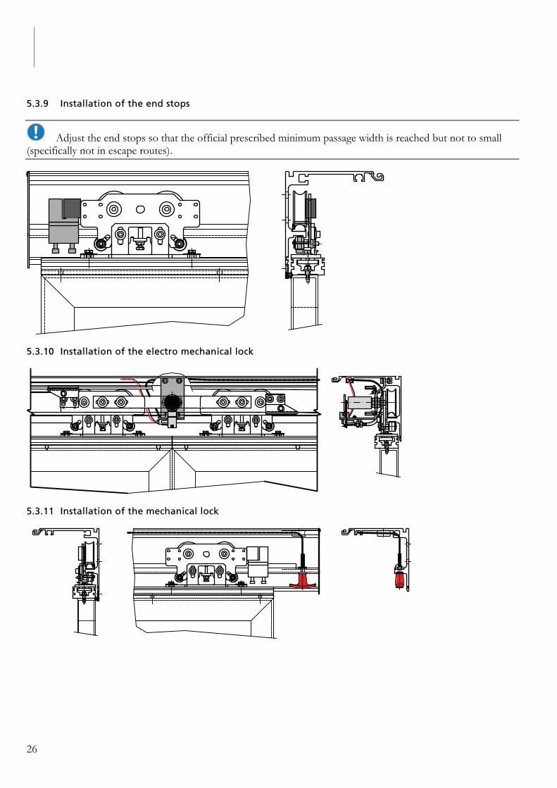
5.3.9 Installation of the end stops
Adjust the end stops so that the official prescribed minimum passage width is reached but not to small (specifically not in escape routes).
5.3.10 Installation of the electro mechanical lock
5.3.11 Installation of the mechanical lock

Automatic Sliding door Installation Manual
27
5.3.12 Connection of program selector
For non-escape routes bridge the contacts when no key switch is connected.
For doors in escape routes always connect a key switch in order to avoid unauthorized use of the program selector!
5.3.13 Installation of the place holder of the header box
2x
Check that the header box is sufficiently connected to the drive unit!

28
5.3.14 Final mechanical testing
Obey the minimum safety distances as described in DIN 18650 part 1, June 2010 (Finger protection). Furthermore secure the friction-free and free movement of the door leaves. Move the door leaves after installation of the carry wheel brackets manually. The movements have to be light and without obstruction.
Check for unusual noises during the movement of the door leaves.
Check all bolt and screw connections.
Check all cables and cable connections.

Automatic Sliding door Installation Manual
29
6.1 Cable installation plan/wiring diagram
1. Program switch 2. Presence contact outside 3. Presence contact inside 4. Program key switch 5. Motion contacts 6. Safety sensor outside 7. Signal lamp 8. Pharmacy opening 9. Escape route opening 10. Interloch 11. Emergency lock release 12. Key switch 13. Escape switch 14. Programmable input 15. Programmable output
16. Extra 17. Extra 18. Extra 19. Extra 20. Power supply 21. Control unit 22. External impulse power cable x 0.35 mm2 23. Main Power cable (3 x 1,5 mm2) 24. Main Switch 25. Escape button 26. Main 230/50 Hz 27. Fuse 16 A Main
Avoid sharp edges or use a cable gland for protection while leading cables through the side cover (left or right).
Cable plan, connection and commissioning may only be executed by authorized personnel.
Cable cross section: Program selector and switch 4 x 0,5 mm2; power supply 3 x 1,5 mm2
6. Start-up

30
6.2 Start-up
1. Plug the Bluetooth adapter or the connection cable in the CSL-CU-400 controller. 2. Connect the operator to the 220/230 volt power supply. 3. Connect the battery to the CSL-CU 400 controller. 4. Verify that the Led flashes on the controller. 5. Start the program (GUI) and establish contact with the controller. 6. Make sure the key (in the GUI) lights up red (Service Modus) 7. Set the safety settings. 8. Check for warnings (GUI). 9. Press the key in GUI to exit service mode.
The door moves slowly into the closed position
The door moves now slowly into the open position.
The door is now ready.
Now, the speed and the hold open time can be set.

Automatic Sliding door Installation Manual
31
For software version v1.02.0054
7.1 Program selection and interaction
The standard ‘state’ of the program selector is the pre-programmed selection and interaction. In this state the actual program is shown on the LEDs and it is possible to change the program.
From this state it is possible to show the error code (if present) and it is possible to switch over the parameter adjustment.
7.1.1 Selecting program
Press the select button to select the program. The program is only changed after the button is released. A press for less then 0.1 seconds or longer then 1 second will be ignored. About 1.5 seconds after the last time the select button is pressed the selected program is transmitted to the controller. Program selection can only be done if it is unlocked. For details see next section.
If a new program has not been selected for more than 10 seconds, the previous program selected will continue.
The selected program is shown using the bar, arrows and the hand symbol.
7.1.2 Locking program selection
Program selection can be locked using an external key switch or the following button combination: keep the reset and interlock button pressed for more than 3 seconds. Unlocking is the same procedure. A change in the lock state is briefly shown on the LEDs and will remain to be displayed until all the buttons have been released. While the lock is active the ‘manual’ LED will blink at a low frequency: 3 seconds off and 0.5 seconds on, with the exception when program manual is selected, then the LED will be 3 seconds on and 0.5 seconds off.
The key switch has priority over the ‘soft’ lock.
Escape routes require an external key switch. Program selection can only be done up to 1 minute after the key switch is set to the unlocked state. After 1 minute the program will be locked again. Unlocking it requires the key switch to be put in the locked state first, followed by the unlocked state.
7.1.3 Show error and warning code
If an error or warning is active on the controller the code can be shown on the LEDs by shortly pressing the reset button. The code will be shown on the LEDs for 5 seconds, after which the display returns to showing the selected program. Pressing the reset button during this time will set this delay again to 5 seconds. This allows for time to look up the error code.
Only one error can be active and will, if active, be shown. If there is no error then a warning code can be shown. Multiple warnings can be active simultaneously. However, only the first warning will be shown. Once that warning has been resolved, the next warning can be shown. The service indication will lid continuous for warnings, flash for error and pulse when the controller is in service mode.
7. Use of CSL program selector
32
7.1.4 Reset error
To reset the error, the reset button must be pressed for more than 1 second. Upon releasing the reset button the reset command is transmitted. Resetting the error can only be done when the program selection is shown.
7.1.5 Initialise door
The door can be re-initialised by pressing the reset button for more than 3 seconds and then giving a short pulse on the select button.
7.1.6 Parameter selection
Some parameters can be changed via the program selector. To change the parameters the interlock button must be pressed for more than 3 seconds, followed by a short pulse on the select button. For more information about parameter adjustment see section parameter adjustment.

Automatic Sliding door Installation Manual
33
7.1.7 Overview button commands
Button(s) pressed Action
Select pulse Change program Reset and interlock pressed > 3 sec Lock / unlock program selection Reset pulse Show error code Reset pressed > 1 sec Reset error Reset pressed > 3 sec + select pulse Initialise door Interlock pressed > 3sec + select pulse Adjust parameters
7.1.8 Overview LED display
Program selection
Program one-way – full Program one-way – reduced
Program automatic – full Program automatic – reduced
Program open – full Program open – reduced
Program manual Program close
Unknown program (Flashing)
Indication keyboard lock changed
Error code, the symbols define the code ( flashing)
Warning code, the symbols define the code ( constant)
Service mode active ( heartbeat)
*) Not allowed in Escape routes
**) in Escape routes: only allowed without lock
Other type of displays: Constant Warning Flashing Error Pulse (like heartbeat) Function “Service” active Error and warning codes

34
Warning codes
Service required
Battery missing
Battery low voltage
Battery operation
Battery hardware of controller
Radar inside bad
Radar outside bad
AIR inside bad
AIR outside bad
I2T activated
Motion disabled
Fire active
Program flow error
Escape module error
AIR inside monitoring error
AIR outside monitoring error
Error codes
Supply failure
Current offset error
Temperature error
Motor drive fault
Motor inverted while operational
Connect motor
Motor shorted
Motor and/or encoder
Encoder error
Low home current
Escape motor movement direction
Memory error
Overvoltage error
Door controller error
Door mechanical connection
No close position
No open position
Software error

Automatic Sliding door Installation Manual
35
7.2 Parameter adjustment
7.2.1 Selecting parameters
A key combination must be entered in order to change parameters. This key combination is the interlock button pressed for more than 3 seconds followed by a pulse on the select button (while still pressing the interlock). The down arrow on in combination with the LED bar indicates that the parameter selection is active.
Use the select button to select the parameter to adjust. Once the parameter has been selected, the combination to change the parameter must be entered. This combination is the interlock button and selected button pressed simultaneously.
Press the reset button to exit the parameter selection menu.
7.2.2 Adjusting parameter values
Once the parameter has been selected (see previous section) and the proper key combination has been entered the parameter value can be adjusted. Parameter adjustment is shown by the up arrow being on and the LED bar to indicate the value. No other LED will be on.
Use the interlock button to change the value and the select button to send the new value to the controller. On pressing the select button the up arrow will shortly be turned off. During this period the value is being transmitted to the controller. The up arrow turns back on once the controller reports the new value. If the value is out of range, for instance due to escape route, the previous value will be reported.
Press the reset button to cancel parameter adjustment. Doing so will return the program selection menu.
7.2.3 Parameters and values
No Parameter Value
1 Open speed Steps of 50 mm/s, starting at 250 2 Open time 1=1s, 2=2s, 3=3s, 4=5s, 5=8s, 6=15s, 7=30s 3 Close speed Steps of 50 mm/sec, starting at 50 4 Reduced open distance Steps of 10% starting at 30% (% of full open)
7.2.4 Overview button commands
Button(s) pressed Action
For parameter selection Interlock pressed > 3 sec + select pulse Change parameters Select pulse Select parameter Reset Return to program selection menu Interlock + select pulse Adjust parameter value For parameter adjustment Interlock + select pulse Adjust parameter value Interlock Change value Select Send new value to controller Reset Cancel adjustment and return to program selection
36
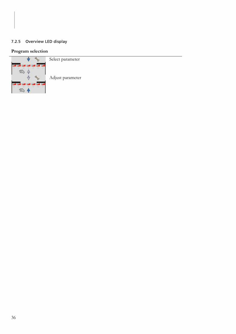
7.2.5 Overview LED display
Program selection
Select parameter
Adjust parameter

Automatic Sliding door Installation Manual
37
8.1 How to Use the Troubleshooting Information
As a member of the service team, your feedback is very important.
Please contact us if you find an error in any of the procedures, or if you have a symptom that is not described in this information.
If you have encoutered a new symptom that should be included in this information, please tell us what the symptom was and how you solved the problem.
We will then assess the input as quickly as possible and include it in this information so that the knowledge is made available to your colleagues.
8.2 Door does not work
Make sure the lights on the position switch are on. When out, press reset button for 5 seconds. Check program selector position. Make sure the main fuse is not blown. Replace the fuse if necessary. Make sure the control unit is engaged. Make sure the LED on the control unit is lighting green. If it is orange, there is a wrong connection, check
wiring. Make sure the door is not obstructed. Release the emergency button when pressed.
8.3 Door does not open
Make sure the lights on the program switch are on. When out, press reset button for 5 seconds. Make sure the control unit has power. Check program selector position. Make sure the main fuse of the power supply is not blown. Replace the fuse if necessary. Make sure the door is not obstructed. Release the emergency button when pressed. Make sure the fire alarm is not active. Make sure that the manual lock in the door is in the unlock position. Make sure that the electronic lock in the operator is in the unlock position. Check the door can be open manually.
8. Troubleshooting
38
8.4 Door does not close
Make sure the door is not obstructed. Clean photocells when activated. Make sure that motion detection is activated. Make sure the key switch is working. Release the emergency button when pressed. Make sure the lights on the program switch are on. When out, press reset button for 5 seconds. Check program selector position. Remove possible moving objects (water, snow) near the door when sensors are activated, and/or
adjust/clean the sensors/radar and check photocells. Make sure wheels are running freely. Make sure the control unit has power. Make sure the main fuse of the power supply is not blown. Replace the fuse if necessary. Make sure the fire alarm is not active. Check all connections.
8.5 Door open and close continuously
Make sure the door is not obstructed. Make sure motion( radar) detection is activated. Remove possible moving objects (water, snow) near the door when sensors are activated, and/or
adjust/clean the sensors/radar and check photocells. Check wheels are running freely.
8.6 Control unit
8.6.1 Door does not open (control unit)
Make sure the control unit is connected and power supply is turned on. Make sure fuses are working and there is enough voltage. Make sure there is a sensor supply. Make sure sensor supply voltage matches the settings. If “Program close” is selected, select program ”Automatic”, ”One way traffic” or “Open”. If Program ”Manual” is selected, select program ”Automatic”, ”One way traffic” or ”Open”. If “Robbery” or ”Disable motion” input is active, select another function for programmable input. If “Battery mode” and ”Battery oper. prog.” is open, set ”Battery oper. prog.” to value other than open. If Sensor input is active, check sensor input, fire input (low active), and set program in case of fire to “Do not use”. LED flashes red when an error occurs. The display of the GUI shows the error message. Reset by pressing
the reset button, by activating the reset input or switching off and then switching on the control unit. Initialisation can be started by activating the external initialisation switch.

Automatic Sliding door Installation Manual
39
8.6.2 Door opens only halfway.
If “Reduced open” has been selected, select “Fully open” program.
8.6.3 Door opens fully and not reduced.
If “Fully open” program was selected,select ”Reduced open” or “Variable open” program. If Programmable input ”FullSens” is activated, connect sensor to “Sensor” input . If “Reduced open position” is incorrect, correct the “Reduced open position” as given in the GUI.
8.6.4 Door does not close.(control unit).
If program ”Open” is selected, select program ”Automatic”, ”One way traffic” or ”Close”. LED flashes red when an error occurs. The GUI shows the error message. Reset by the program selector.
Initialisation can be started by activating the external initialisation switch. If sensor remains active, check the sensors safety and porter. If the door does not open after start-up, but
remains open when another sensor actives, check the safety sensors. If battery mode and battery oper. prog. is set to close, set battery oper. prog. to normal If fire input is active and program if fire is open, check fire input and set program if fire to another value.
8.6.5 Automatic return system activates
If maximum current is too low, increase the maximum motor current and increase the l2T time If automatic return system is too sensitive, decrease the sensitivity and increase current gain. If automatic return system activates when just closed, increase the “Close offset”. If the acceleration too high, lower the acceleration. If motor parameters are incorrect, correct to motor parameter.
8.6.6 Door movement is jerky.
Check encoder operation. Check encoder cable. Check cable shielding.
8.6.7 Door opens or closes slowly.
If battery mode is on check if mains is present and check supply voltage. If the supply voltage is low, check supply voltage.
8.6.8 Close position is incorrect.
Make sure the correct value is given for close direction.
8.6.9 LED color.
Flashes red. An error has occurred. Flashes orange. A warning is active. Flashes green. Normal operation. Flashes orange. CSL Service mode. Flashes red/orange. Software updating.
o Check that the LED of the CSL is on (blinking green or continues orange). If it is off then there is no power supplied to the controller.
If the LED continues orange then the main controller is in a reset state. Make sure that the escape open switch is in the correct position (0 is normal operation).

40
8.6.10 Program changes not applied.
Error active. Fix problem and resend. Warning active. Remove cause of warning.
8.7 Errors in controller
The controller can have the following error messages:
Supply voltage
Meaning: The supply voltage was lower than 18V or higher than 60V. Cause: Inadequate power supply (voltage drops when loading supply), disturbance on mains. No close position
Meaning: The close position cannot be found. During the search for the close position the maximum distance of 30 meter has been exceeded.
Cause: Belt broken, gear defective, pulley slips. No open position
Meaning: The open position cannot be found. During the search for the fully open position the maximum distance of 30 meter has been exceeded, or it is smaller than 250 mm.
Cause: Gear defective, pulley slips, belt broken, door blocked or moves difficult, maximum motor current to low.
If this error is caused because the door is blocked to keep it open, then setting parameter AutoReverse init to Off can prevent the automatic initialisation after 10 consecutive activations of the automatic return system.
High temperature
Meaning: The temperature of the controller is higher than 50°C Cause: Ambient temperature too high, load too big.
Motor/encoder
Meaning: Door could not be stopped after the automatic return system activated. Cause: Motor faulty, encoder faulty, motor parameters incorrect, bad connection.
Connect motor
Meaning: Motor not connected, current through motor to low. Cause: Motor not connected, bad connection, motor parameters incorrect, motor defective, low power
supply voltage.

Automatic Sliding door Installation Manual
41
Encoder
Meaning: Error with encoder, motor or lock. Cause: Encoder not connected, bad connection, encoder faulty, door at end post, motor blocked, lock
active, improper shielding, maximum motor current to low, friction to high. This error message is used when the encoder does not change significantly during the test and a current is measured through the motor, which will be the case if the motor cannot turn, caused by a blocked motor or the lock being active. Another cause can be a bad connection between the motor and the controller or improper shielding, which causes interference on the encoder lines. If the current through the motor is not sufficient to move the door, either the “Max.motorcurrent” or the I2T time is to low. During initialisation, this error can occur when the motor wires are swapped and the door is at the end post, which does not result in a position change to test the encoder. The controller will automatically swap the motor wires through the software during initialisation. Opening the door, which allows a movement in both directions, can prevent this error.
Storing values
Meaning: There was a problem storing the values of the parameters. Cause: Memory defective.
Bios version
Meaning: Sliding door software requires newer version of the BIOS Cause: Old version, upgrade the BIOS. The new version of the software requires a newer version BIOS.
Unknown error
Meaning: Unknown error (error list only.) Cause: Caused by a software update where old values were stored in the error list.
Clear the error list by pressing the reset button on the Programmer terminal.
No error
Meaning: No error (error list only) Cause: This position in the error list does not have an error (error cleared).

42
9. Wiring diagram
Automatic Sliding door Installation Manual
43
Sensor Input Protocol:
1. Relays contact 2. Frequency input 3. Voltage input 4. Pnp input 5. Npn input 6. Redundant
This control unit: Is designed to ba able for all types of sensors that need to be monitored. And you can configure all the parameters setting in the software.
7. Main motor encoder 8. Main motor 9. Power supply 10. Escape motor 11. Escape encoder 12. Key switch 13. Lock 14. Program switch 15. Sensor outside 16. Sensor inside 17. Programmable inputs 18. Battery Supply 19. Fuse 2x 6,3 A 20. Control Unit