
8 th January, 2007 European Linear Collider Workshop, DL, UK ILC DR Vacuum System Progress in ECLOUD...
21
8 th January, 2007 European Linear Collider Workshop, DL, UK ILC DR Vacuum System Progress in ECLOUD Task (Goal 7) for the ILC DR Dr. Oleg B. Malyshev ASTeC CCLRC Daresbury Laboratory
-
Upload
lydia-fletcher -
Category
Documents
-
view
215 -
download
2
Transcript of 8 th January, 2007 European Linear Collider Workshop, DL, UK ILC DR Vacuum System Progress in ECLOUD...
8th January, 2007 European Linear Collider Workshop, DL, UK
ILC DR Vacuum SystemProgress in ECLOUD Task (Goal 7) for the ILC DR
Dr. Oleg B. Malyshev
ASTeC
CCLRC Daresbury Laboratory

8th January, 2007 European Linear Collider Workshop, DL, UK O.B. Malyshev
Required vacuum
The need to avoid fast ion instability leads to very demanding specifications for the vacuum in the electron damping ring [Lanfa Wang, private communication]:
< 0.5 nTorr CO in the arc cell, < 2 nTorr CO in the wiggler cell and < 0.1 nTorr CO in the straight section
In the positron damping ring required vacuum level was not specified and assumed as 1 nTorr (common figure for storage rings)

8th January, 2007 European Linear Collider Workshop, DL, UK O.B. Malyshev
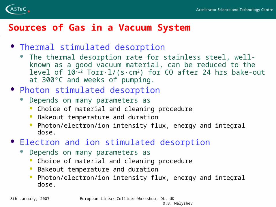
Sources of Gas in a Vacuum System
Thermal stimulated desorption The thermal desorption rate for stainless steel, well-known as a good
vacuum material, can be reduced to the level of 10-12 Torr·l/(s·cm2) for CO after 24 hrs bake-out at 300ºC and weeks of pumping.
Photon stimulated desorption Depends on many parameters as
Choice of material and cleaning procedure Bakeout temperature and duration Photon/electron/ion intensity flux, energy and integral dose.
8th January, 2007 European Linear Collider Workshop, DL, UK O.B. Malyshev
Sources of Gas in a Vacuum System
Thermal stimulated desorption The thermal desorption rate for stainless steel, well-known as a good
vacuum material, can be reduced to the level of 10-12 Torr·l/(s·cm2) for CO after 24 hrs bake-out at 300ºC and weeks of pumping.
Photon stimulated desorption Depends on many parameters as
Choice of material and cleaning procedure Bakeout temperature and duration Photon/electron/ion intensity flux, energy and integral dose.
Electron and ion stimulated desorption Depends on many parameters as
Choice of material and cleaning procedure Bakeout temperature and duration Photon/electron/ion intensity flux, energy and integral dose.
8th January, 2007 European Linear Collider Workshop, DL, UK O.B. Malyshev
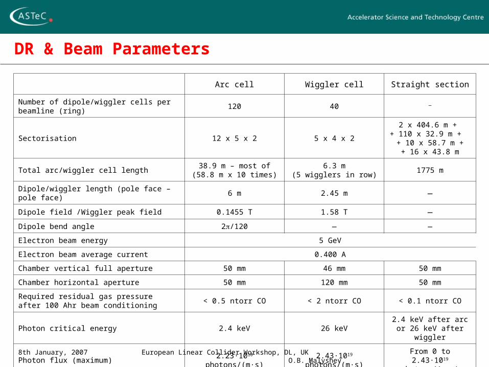
DR & Beam Parameters
Arc cell Wiggler cell Straight section
Number of dipole/wiggler cells per beamline (ring) 120 40 —
Sectorisation 12 x 5 x 2 5 x 4 x 2
2 x 404.6 m + + 110 x 32.9 m +
+ 10 x 58.7 m ++ 16 x 43.8 m
Total arc/wiggler cell length38.9 m – most of
(58.8 m x 10 times)6.3 m
(5 wigglers in row)1775 m
Dipole/wiggler length (pole face – pole face) 6 m 2.45 m —
Dipole field /Wiggler peak field 0.1455 T 1.58 T —
Dipole bend angle 2/120 — —
Electron beam energy 5 GeV
Electron beam average current 0.400 A
Chamber vertical full aperture 50 mm 46 mm 50 mm
Chamber horizontal aperture 50 mm 120 mm 50 mm
Required residual gas pressureafter 100 Ahr beam conditioning
< 0.5 ntorr CO < 2 ntorr CO < 0.1 ntorr CO
Photon critical energy 2.4 keV 26 keV2.4 keV after arc
or 26 keV after wiggler
Photon flux (maximum) 2.23·1018 photons/(m·s) 2.43·1019 photons/(m·s)From 0 to
2.43·1019 photons/(m·s)

8th January, 2007 European Linear Collider Workshop, DL, UK O.B. Malyshev
Photon flux onto the 50-mm diameter vacuum chamber walls inside the dipoles and along the short straights
0 10 20 30 40 501 10
15
1 1016
1 1017
1 1018
1 1019
SR from 1st dipole inside 1st dipole VCSR from 1st dipole along 1st straightSR from 1st dipole inside 2nd dipole SR from 2nd dipole inside 2nd dipole SR from 2nd dipole along 2nd straight
Photon flux from dipole
Distance from dipole (m)
Pho
ton
flux
(ph
oton
s/(s
*m))
.

8th January, 2007 European Linear Collider Workshop, DL, UK O.B. Malyshev
Photodesorption yield and flux along the damping ring straights made of stainless steel tubular vacuum chamber and baked in-situ at 300C for 24 hrs.
0 10 20 30 40 501 10
7
1 106
1 105
1 104 Short straights
Phot
odes
orpt
ion
yiel
d (m
olec
ules
/pho
ton)
0 50 100 150 200 250 300 350 4001 10
6
1 105
1 104 Long straights
Phot
odes
orpt
ion
yiel
d (m
olec
ules
/pho
ton)
0 10 20 30 40 501 10
10
1 1011
1 1012
1 1013
1 1014
1 1015
initialafter 0.1 A hrsafter 1 A hrsafter 10 A hrsafter 100 A hrsThermal desorption
Distance from dipole (m)
Des
orpt
ion
flux
(mol
ecul
es/s
/m)
0 50 100 150 200 250 300 350 4001 10
9
1 1010
1 1011
1 1012
1 1013
1 1014
1 1015
initialafter 0.1 A hrsafter 1 A hrsafter 10 A hrsafter 100 A hrsThermal desorption
Distance from dipole (m)
Des
orpt
ion
flux
(mol
ecul
es/s
/m)
8th January, 2007 European Linear Collider Workshop, DL, UK O.B. Malyshev
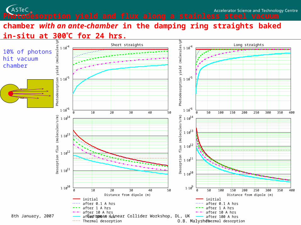
Photodesorption yield and flux along a stainless steel vacuum chamber with an ante-chamber in the damping ring straights baked in-situ at 300C for 24 hrs.
0 10 20 30 40 501 10
6
1 105
1 104 Short straights
Phot
odes
orpt
ion
yiel
d (m
olec
ules
/pho
ton)
0 50 100 150 200 250 300 350 4001 10
6
1 105
1 104 Long straights
Phot
odes
orpt
ion
yiel
d (m
olec
ules
/pho
ton)
0 10 20 30 40 501 10
10
1 1011
1 1012
1 1013
1 1014
initialafter 0.1 A hrsafter 1 A hrsafter 10 A hrsafter 100 A hrsThermal desorption
Distance from dipole (m)
Des
orpt
ion
flux
(mol
ecul
es/s
/m)
0 50 100 150 200 250 300 350 4001 10
9
1 1010
1 1011
1 1012
1 1013
1 1014
initialafter 0.1 A hrsafter 1 A hrsafter 10 A hrsafter 100 A hrsThermal desorption
Distance from dipole (m)
Des
orpt
ion
flux
(mol
ecul
es/s
/m)
10% of photons hit vacuum chamber
8th January, 2007 European Linear Collider Workshop, DL, UK O.B. Malyshev
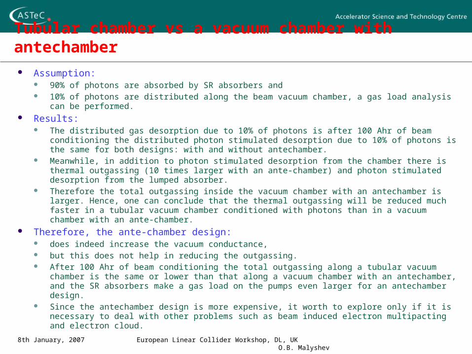
Tubular chamber vs a vacuum chamber with antechamber
Assumption: 90% of photons are absorbed by SR absorbers and 10% of photons are distributed along the beam vacuum chamber, a gas load analysis can be
performed. Results:
The distributed gas desorption due to 10% of photons is after 100 Ahr of beam conditioning the distributed photon stimulated desorption due to 10% of photons is the same for both designs: with and without antechamber.
Meanwhile, in addition to photon stimulated desorption from the chamber there is thermal outgassing (10 times larger with an ante-chamber) and photon stimulated desorption from the lumped absorber.
Therefore the total outgassing inside the vacuum chamber with an antechamber is larger. Hence, one can conclude that the thermal outgassing will be reduced much faster in a tubular vacuum chamber conditioned with photons than in a vacuum chamber with an ante-chamber.
Therefore, the ante-chamber design: does indeed increase the vacuum conductance, but this does not help in reducing the outgassing. After 100 Ahr of beam conditioning the total outgassing along a tubular vacuum chamber is the
same or lower than that along a vacuum chamber with an antechamber, and the SR absorbers make a gas load on the pumps even larger for an antechamber design.
Since the antechamber design is more expensive, it worth to explore only if it is necessary to deal with other problems such as beam induced electron multipacting and electron cloud.

8th January, 2007 European Linear Collider Workshop, DL, UK O.B. Malyshev
TiZrV NEG coating for accelerator vacuum chambers
A new vacuum technology for accelerators developed at CERN in recent years [i], is the use of TiZrV (NEG) coating for all inner surfaces of the vacuum chamber.
TiZrV films have been intensively studied by vacuum groups in many different laboratories [ii].
TiZrV coated vacuum chambers: are already used in accelerators:
for six years at the ESRF [iii] and for 4 years at ELETTRA [iv];
many others are just beginning (RHIC, Soleil, Diamond) or will use them in future.
[i] C. Benvenuti. Non-Evaporable Getters : from Pumping Strips to Thin Film Coatings. EPAC '98 , Stockholm, Sweden , 22 - 26 Jun 1998, pp. 200-204.
[ii] 45th IUVSTA Workshop on NEG coatings for particle accelerators and vacuum systems. 5-8 April 2006. Catania, Italy. www.iuvsta.org.
[iii] M. Hahn and R. Kersevan. Status of NEG coating at ESRF. Proc. of 2005 Particle Accelerator Conference, Knoxville, Tennessee, pp. 422-424.
[iv] F. Mazzolini, L. Rumiz, J. Miertusova, F. Pradal. Ten years of ELETTRA vacuum system experience. Vacuum 73 (2004) 225–229.
[v] V.V. Anashin, I.R. Collins, R.V. Dostovalov, N.V. Fedorov, A.A. Krasnov, O.B. Malyshev and V.L. Ruzinov. Comparative study of photodesorption from TiZrV coated and uncoated stainless steel vacuum chambers. Vacuum 75 (2), July 2004, pp. 155-159.

8th January, 2007 European Linear Collider Workshop, DL, UK O.B. Malyshev
TiZrV NEG coating for accelerator vacuum chambers
A 1-micron NEG coating used on a vacuum chamber made of stainless steel, copper or aluminium : reduces the outgassing from the vacuum chamber walls (between 10 and 200
times less than in-situ baked stainless steel) and introduces a distributed pumping speed, resulting in lower gas density in a
beam vacuum chamber [v]. The only gases which are not pumped by such a coating are hydrocarbons and noble gases; these requires the use of other pumps, (for example, sputter ion pumps) but with much lower pumping speed.
The use of NEG coating requires activation, i.e. 24 hours bakeout at 180C.
In a positron DR the NEG coating also will play a role of an anti-multipacting coating due to low SEY.
Thermal stimulated desorption from the NEG is negligible; the pressure inside the NEG coated chamber without SR is less than 10-13 Torr (Helmer gauge limit)

8th January, 2007 European Linear Collider Workshop, DL, UK O.B. Malyshev
Pressure calculations
The average pressure can be calculated as a function of a distance between pumps L or as a function pumping speed S
For two cases without or with distributed pumping speed C
2 tanh2
( ) 1 ,
1 tanh2
where
L
n LC u L
LS
C u
1( )
12 2
Ln L L
u S
Pumping ports
8th January, 2007 European Linear Collider Workshop, DL, UK O.B. Malyshev
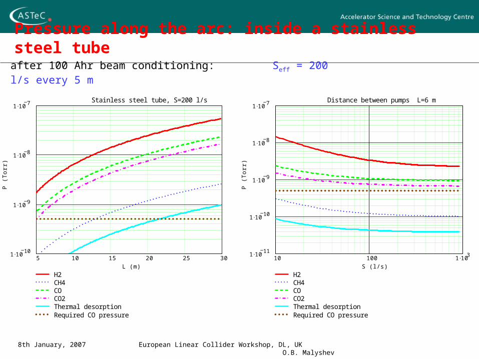
Pressure along the arc: inside a stainless steel tube
5 10 15 20 25 301 10
10
1 109
1 108
1 107
H2CH4COCO2Thermal desorptionRequired CO pressure
Stainless steel tube, S=200 l/s
L (m)
P (
To
rr)
10 100 1 1031 10
11
1 1010
1 109
1 108
1 107
H2CH4COCO2Thermal desorptionRequired CO pressure
Distance between pumps L=6 m
S (l/s)
P (
To
rr)
after 100 Ahr beam conditioning: Seff = 200 l/s every 5 m
8th January, 2007 European Linear Collider Workshop, DL, UK O.B. Malyshev
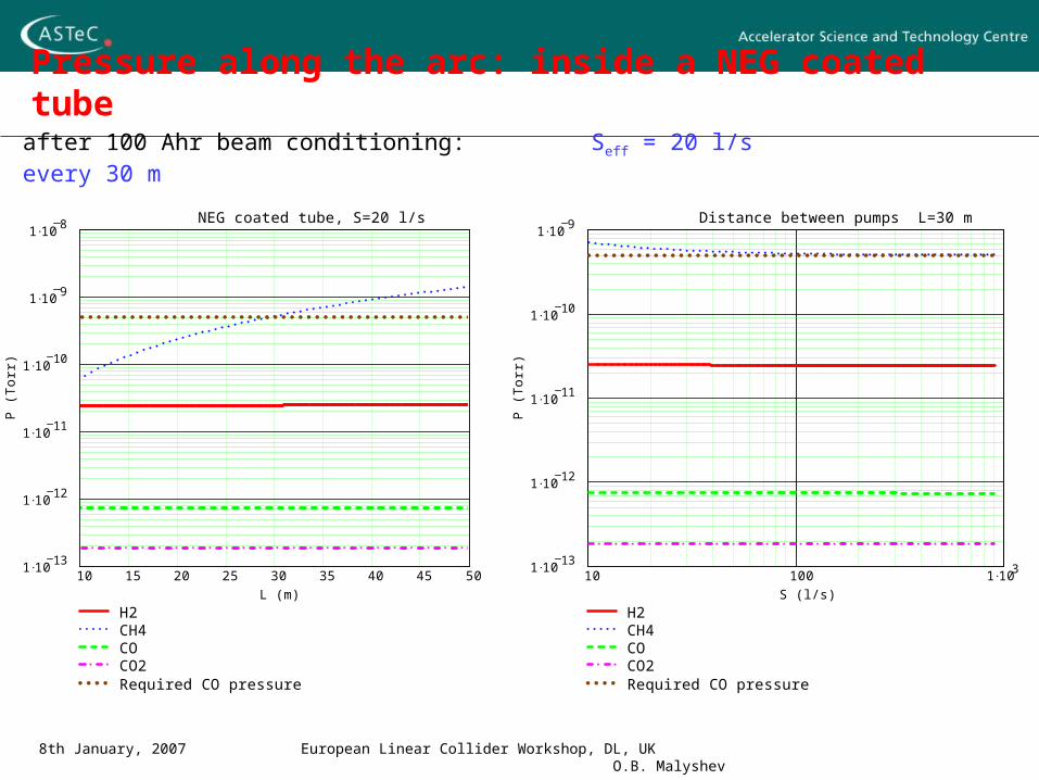
Pressure along the arc: inside a NEG coated tube
10 15 20 25 30 35 40 45 501 10
13
1 1012
1 1011
1 1010
1 109
1 108
H2CH4COCO2Required CO pressure
NEG coated tube, S=20 l/s
L (m)
P (T
orr)
10 100 1 1031 10
13
1 1012
1 1011
1 1010
1 109
H2CH4COCO2Required CO pressure
Distance between pumps L=30 m
S (l/s)
P (T
orr)
after 100 Ahr beam conditioning: Seff = 20 l/s every 30 m
8th January, 2007 European Linear Collider Workshop, DL, UK O.B. Malyshev
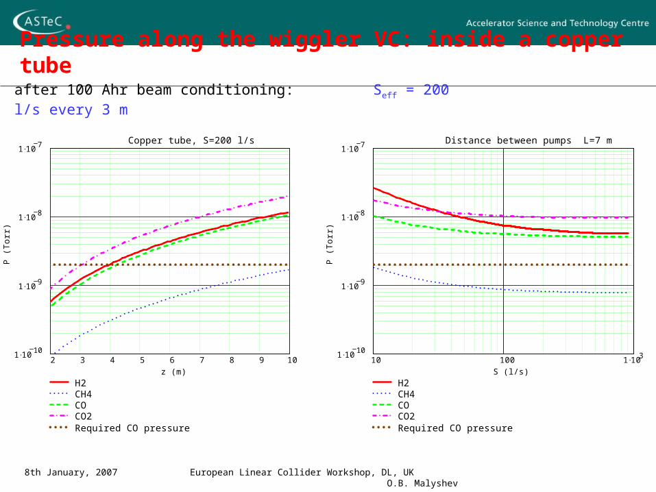
Pressure along the wiggler VC: inside a copper tubeafter 100 Ahr beam conditioning: Seff = 200 l/s every 3 m
2 3 4 5 6 7 8 9 101 10
10
1 109
1 108
1 107
H2CH4COCO2Required CO pressure
Copper tube, S=200 l/s
z (m)
P (T
orr)
10 100 1 1031 10
10
1 109
1 108
1 107
H2CH4COCO2Required CO pressure
Distance between pumps L=7 m
S (l/s)
P (T
orr)

8th January, 2007 European Linear Collider Workshop, DL, UK O.B. Malyshev
Pressure along the wiggler VC: inside a NEG coated tube
10 15 20 25 30 35 40 45 501 10
13
1 1012
1 1011
1 1010
1 109
1 108
H2CH4COCO2Required CO pressure
NEG coated tube, S=20 l/s
L (m)
P (T
orr)
10 100 1 1031 10
13
1 1012
1 1011
1 1010
1 109
H2CH4COCO2Required CO pressure
Distance between pumps L=30 m
S (l/s)
P (T
orr)
after 100 Ahr beam conditioning: Seff = 20 l/s every 30 m

8th January, 2007 European Linear Collider Workshop, DL, UK O.B. Malyshev
Pressure along the stainless steel Long Straight sections
4 6 8 10 12 14 161 10
11
1 1010
1 109
1 108
H2CH4COCO2Thermal desorptionRequired CO pressure
Stainless steel tube, S=100 l/s
L (m)
P (T
orr)
10 100 1 1031 10
11
1 1010
1 109
1 108
H2CH4COCO2Thermal desorptionRequired CO pressure
Distance between pumps L=6 m
S (l/s)
P (T
orr)
qlowqd
105
after 100 Ahr beam conditioning
40 m downstream from a dipole Seff = 100 l/s every 6 m
170 m downstream from a dipole Seff = 100 l/s every 10 m
4 6 8 10 12 14 16 18 201 10
11
1 1010
1 109
H2CH4COCO2Thermal desorptionRequired CO pressure
Stainless steel tube, S=100 l/s
L (m)
P (T
orr)
10 100 1 1031 10
12
1 1011
1 1010
1 109
H2CH4COCO2Thermal desorptionRequired CO pressure
Distance between pumps L=10 m
S (l/s)
P (T
orr)

8th January, 2007 European Linear Collider Workshop, DL, UK O.B. Malyshev
Pressure along the NEG coated Long Straight sections
after 100 Ahr beam conditioning
40 m downstream from a dipole Seff = 20 l/s every 10 m
170 m downstream from a dipole Seff = 20 l/s every 40 m
5 10 15 20 25 301 10
13
1 1012
1 1011
1 1010
1 109
H2CH4COCO2Required CO pressure
NEG coated tube, S=20 l/s
L (m)
P (T
orr)
10 100 1 1031 10
13
1 1012
1 1011
1 1010
1 109
H2CH4COCO2Required CO pressure
Distance between pumps L=10 m
S (l/s)
P (T
orr)
10 20 30 40 50 60 70 80 90 1001 10
14
1 1013
1 1012
1 1011
1 1010
1 109
H2CH4COCO2Required CO pressure
NEG coated tube, S=20 l/s
L (m)
P (T
orr)
10 100 1 1031 10
14
1 1013
1 1012
1 1011
1 1010
1 109
H2CH4COCO2Required CO pressure
Distance between pumps L=40 m
S (l/s)
P (T
orr)
8th January, 2007 European Linear Collider Workshop, DL, UK O.B. Malyshev
Electron multipacting effect on vacuum
The photon stimulated desorption is a two-step process:
Photoelectron emission (E1 =~5-10 eV and E2 =~ E, PEY=~0.1 e-/ )
Electron stimulated molecular desorption
The electron stimulated desorption grow with electron energy and electron flux
hitting the vacuum chamber.
For example, for Ee-= 100 eV and e-= 1016 e-/(ms), the electron stimulated gas
desorption is comparable to the photon stimulated desorption for = 1017 /(ms)
(~8 m downstream dipole). I.e. the electron multipacting may affect on vacuum,
new results of e-cloud modelling are required for different parts of DR.
If the electron multipacting is significant on long straights, it will badly affect the
vacuum performance as no vacuum conditioning will be done there with photons.
8th January, 2007 European Linear Collider Workshop, DL, UK O.B. Malyshev
Main results of the modelling
NEG coating of vacuum chamber along both the arcs and the wigglers as well as a few tens meters downstream of both looks to be the only possible solution to fulfil vacuum requirement for the ILC dumping ring
Beam induces electron Multipacting (BIEM) looks to make negligible impact inside dipoles and wigglers, but it might affect on the straights vacuum design and the beam conditioning scenario. E-cloud modelling results are needed!
Power dissipation from SR (and BIEM if there is any) have to be considered: vacuum chamber water cooling is required in wigglers, arcs and a few tenth
meters downstream of both. end power absorber for SR from the wiggler (at first dipole downstream a
wiggler) NEG coated power absorber for wiggler vacuum chamber needs to be
studied experimentally.

8th January, 2007 European Linear Collider Workshop, DL, UK O.B. Malyshev
Ideal vacuum chamber for ILC DR
Round or elliptical tube Cheapest from technological point of view
No antechamber Beam conditioning is most efficient
NEG coated Requires less number of pumps with less pumping speed 180C for NEG activation instead of 250-300C bakeout Choice of vacuum chamber material (stainless steel, copper and
aluminium ) does not affect vacuum in this case Residual gas CH4 and H2 (almost no CO and CO2)
There are experimental results that NEG coated elliptical vacuum chamber might be re-activated even without baking to 180C, just by SR. Accurate experimental study is needed


![ILC DR lattice - Cornell University · Yi-Peng Sun et al. ILC DR Alternative Lattice Design 20 LOW ALPHA LATTICE (3) Natural energy spread [ 10-3] 1.28 Natural bunch length [ mm ]](https://static.fdocuments.us/doc/165x107/6101cd08e8e2923eb56cf1e2/ilc-dr-lattice-cornell-university-yi-peng-sun-et-al-ilc-dr-alternative-lattice.jpg)