8 Register, Multiplexer and Three-State...
64
For further assistance, email [email protected] or call your local support center HOME CONTENTS INDEX 8 Register, Multiplexer and Three-State Inference HDL Compiler can infer F Registers (latches and flip–flops) F Multiplexers F Three–state gates This chapter discusses methods of inferring different types of registers, multiplexers and three–state devices in the following sections and subsection Register Inference — Using Register Inference — Describing Latches — Describing Flip–flops — Additional Types of Register Inference — Attributes — Efficient Use of Registers
Transcript of 8 Register, Multiplexer and Three-State...

For further assistance, email [email protected] or call your local support center
HOME CONTENTS INDEX
8 Register, Multiplexer andThree-State Inference
HDL Compiler can infer
� Registers (latches and flip–flops)
� Multiplexers
� Three–state gates
This chapter discusses methods of inferring different types ofregisters, multiplexers and three–state devices in the followingsections and subsection
Register Inference— Using Register Inference— Describing Latches— Describing Flip–flops— Additional Types of Register Inference— Attributes— Efficient Use of Registers

VHDL Compiler Reference V3.4
For further assistance, email [email protected] or call your local support center
HOME CONTENTS INDEX
Multiplexers— New VHDL Attribute— New Variables for Multiplexer Inference— Uses of Variables and Attributes— New Inference Report— Example of Multiplexer Inference and its Correspond-
ing Inference Report Three–State Inference
— Assigning the Value ’Z’— Latched Three–State Variables
Register InferenceA register is a simple, one-bit memory device, either a flip-flopor a latch. A flip-flop is an edge-triggered memory device. Alatch is a level-sensitive memory device.
VHDL Compiler performs register inferencing using the wait
and if statements.
Use the wait statement to imply flip-flops in a synthesizedcircuit. VHDL Compiler creates flip-flops for all signals andsome variables assigned values in a process with a wait
statement.
The if statement can be used to imply registers (flip-flops orlatches) for signals and variables in the branches of the ifstatement.

VHDL Compiler Reference V3.4
For further assistance, email [email protected] or call your local support center
HOME CONTENTS INDEX
Using Register InferenceThis section describes several elements needed to use theregister inference capability of VHDL Compiler. Examples areprovided of how to describe clocked signals and when to usewait or if statements. This section also describes recom-mended models for different types of inferred registers, aswell as several restrictions on register inference capabilities.
Use the wait and if statements to test for the rising or fallingedge of a signal. The most common usages are
processbegin wait until ( edge ); ...end process;...
process ( sensitivity_list )begin if ( edge ) ... end if;end process;
Another form is
process ( sensitivity_list )begin if (...) then ... elsif (...) ... elsif ( edge ) then ... end if;end process;

VHDL Compiler Reference V3.4
For further assistance, email [email protected] or call your local support center
HOME CONTENTS INDEX
edge refers to an expression that tests for the positive or nega-tive edge of a signal. The syntax of an edge expression is
SIGNAL’event and SIGNAL = ’1’ –– rising edgeNOT SIGNAL’stable and SIGNAL = ’1’ –– rising edge
SIGNAL’event and SIGNAL = ’0’ –– falling edgeNOT SIGNAL’stable and SIGNAL = ’0’ –– falling edge
In a wait statement, edge can also be
signal = ’1’ –– rising edgesignal = ’0’ –– falling edge
An edge expression must be the only condition of an if or anelsif . You can have only one edge expression in an if , andthe if must not have an else clause. An edge expressioncannot be part of another logical expression nor used as anargument.
if ( edge and RST = ’1’) –– Illegal usage; edge must be only condition
Any_function( edge ); –– Illegal usage; edge cannot be an argument
if X > 5 then sequential_statement;elsif edge then sequential_statement;else sequential_statement;end if; –– Illegal usage; do not use an else clause for not edge
The lines above illustrate three incorrect uses. In the firstgroup, the expression is part of a larger BOOLEAN expression. Inthe second group, the edge expression is used as an argu-ment. In the third group, the edge expression is used as anintermediate condition.

VHDL Compiler Reference V3.4
For further assistance, email [email protected] or call your local support center
HOME CONTENTS INDEX
wait vs. if Statementswait and if statements can sometimes be used interchange-ably. The if statement is usually preferred, since it providesgreater control over the inferred register’s capabilities, asdescribed in the next section.
IEEE VHDL requires that a process with a wait statementcannot have a sensitivity list.
An if edge statement in a process can occur anywhere inthat process. The process’ sensitivity list must contain allsignals read in the process, including the edge signal. In gener-al, the following guidelines apply:
� Synchronous processes (processes that compute valuesonly on clock edges) must be sensitive to the clocksignal.
� Asynchronous processes (processes that computevalues on clock edges and when asynchronous condi-tions are TRUE) must be sensitive to the clock signal (ifany), and to inputs that affect asynchronous behavior.
Recommended Use of Register Inference CapabilitiesThe register inference capability can support coding stylesother than those described here. However, for best results
� Restrict each process to a single type of memory-ele-ment inferencing: latch, latch with asynchronous set orreset, flip-flop, flip-flop with asynchronous reset, or flip-flop with synchronous reset.
� Use the following templates
LATCH: process( sensitivity_list ) begin if LATCH_ENABLE then ... end if;

VHDL Compiler Reference V3.4
For further assistance, email [email protected] or call your local support center
HOME CONTENTS INDEX
end process;
LATCH_ASYNC_SET: ...attribute async_set_reset of SET : signal is “true”; ... process( sensitivity_list ) begin if SET then Q <= ’1’; elsif LATCH_ENABLE then ... end if; end process;FF: process(CLK) begin if edge then ... end if; end process;FF_ASYNC_RESET: process(RESET, CLK) begin if RESET then Q <= ’0’; elsif edge then Q <= ...; end if; end process;FF_SYNC_RESET: process(RESET, CLK) begin if edge then if RESET then Q <= ’0’; else Q <= ...; end if; end if; end process;
For examples of these templates see ‘‘Describing Latches”and ‘‘Describing Flip-flops,” later in this chapter.

VHDL Compiler Reference V3.4
For further assistance, email [email protected] or call your local support center
HOME CONTENTS INDEX
Restrictions on Register CapabilitiesDo not use more than one if edge expression in a process.
process(CLK_A, CLK_B) begin if(CLK_A’event and CLK_A = ’1’) then A <= B; end if; if(CLK_B’event and CLK_B = ’1’) then –– Illegal C <= B; end if; end process;
Do not assign a value to a variable or signal on a FALSE
branch of an if edge statement. To make such an assign-ment is equivalent to checking for the absence of a clockedge, which has no hardware counterpart.
process(CLK) begin if(CLK’event and CLK = ’1’) then SIG <= B; else SIG <= C; –– Illegal end if; end process;
If a variable is assigned a value inside an edge construct, donot read that variable later in the same process.
process(CLK) variable EDGE_VAR, ANY_VAR: STD_LOGIC;
begin if (CLK’event and CLK = ’1’) then EDGE_SIGNAL <= X; EDGE_VAR := Y; ANY_VAR := EDGE_VAR; –– Legal end if; ANY_VAR := EDGE_VAR; –– Illegal
end process;
Do not use an edge expression as an operand.
if not(CLK’event and CLK = ’1’) then –– Illegal

VHDL Compiler Reference V3.4
For further assistance, email [email protected] or call your local support center
HOME CONTENTS INDEX
Delays in RegistersUsing delay specifications with values that are registered cancause the simulation to behave differently from the logicsynthesized by VHDL Compiler. For example, the descriptionin Example 8–1 contains delay information that causes DesignCompiler to synthesize a circuit that behaves unexpectedly(i.e., post–synthesis simulation results do not match pre–syn-thesis simulation results).
Example 8–1 Delays in Registers
component flip_flop ( D, clock: in std_logic; Q: out std_logic;);end component;
process ( A, C, D, clock ); signal B: std_logic;begin
B <= A after 100ns;
F1: flip_flop port map ( A, C, clock ),F2: flip_flop port map ( B, D, clock );
end process;
In Example 8–1, B changes 100 nanoseconds after Achanges. If the clock period is less than 100 nanoseconds,output D is one or more clock cycles behind output C whenthe design is simulated. However, because VHDL Compilerignores the delay information, A and B change values at thesame time, and so do C and D . This behavior is not the sameas in the post–synthesis simulation.
When using delay information in your designs, make sure thatthe delays do not affect registered values. In general, youcan safely include delay information in your description if itdoes not change the value that gets clocked into a flip-flop.

VHDL Compiler Reference V3.4
For further assistance, email [email protected] or call your local support center
HOME CONTENTS INDEX
Describing LatchesVHDL Compiler infers latches from incompletely specifiedconditional expressions. For example, the following if state-ment infers a latch because there is no else clause:
Example 8–2 Latch Inference
process(GATE, DATA)begin if (GATE = ’1’) then Q <= DATA; end if;end process;
Figure 8–1 Latch Inference
The inferred latch uses CLK as its clock and DATA as its datainput, as shown in Example 8–2.

VHDL Compiler Reference V3.4
For further assistance, email [email protected] or call your local support center
HOME CONTENTS INDEX
Automatic Latch InferencingA signal or variable that is not driven under all conditionsbecomes a latched value. As shown in Example 8–3, TEMP
becomes a latched value because it is assigned only whenPHI is 1.
Example 8–3 Automatically Inferred Latch
if(PHI = ’1’) then TEMP <= A;end if;
Figure 8–2 Automatically Inferred Latch
To avoid having a latch inferred, assign a value to the signalunder all conditions, as shown in Example 8–4.
Example 8–4 Fully Specified Signal: No Latch Inference
if (PHI = ’1’) then TEMP <= A;else TEMP <= ’0’;end if;
Figure 8–3 Fully Specified Signal: No Latch Inference

VHDL Compiler Reference V3.4
For further assistance, email [email protected] or call your local support center
HOME CONTENTS INDEX
Restrictions on Latch Inference CapabilitiesYou cannot read a conditionally–assigned variable after theif statement in which it is assigned. A conditionally–assignedvariable is assigned a new value under some, but not all,conditions.
That is, a variable must always have a value before it is read.
signal X, Y: STD_LOGIC;. . .process variable VALUE: STD_LOGIC;;begin
if ( condition ) then VALUE := X; end if;
Y <= VALUE; –– Illegalend;
In simulation, latch inference occurs because signals andvariables can hold state over time. A signal or variable holdsits value until that value is reassigned. VHDL Compiler insertsa latch to duplicate this holding–of–state in hardware.
Variables declared locally within a subprogram do not holdtheir value over time. Every time a subprogram is used, itsvariables are reinitialized. Therefore, VHDL Compiler does notinfer latches for variables declared in subprograms. InExample 8–5 no latches are inferred.

VHDL Compiler Reference V3.4
For further assistance, email [email protected] or call your local support center
HOME CONTENTS INDEX
Example 8–5 Function without Inferred Latch
function MY_FUNC(DATA, GATE : STD_LOGIC) return STD_LOGIC is variable STATE: STD_LOGIC;begin if GATE then STATE := DATA; end if; return STATE;end;. . .Q <= MY_FUNC(DATA, GATE);
Figure 8–4 Function without Inferred Latch
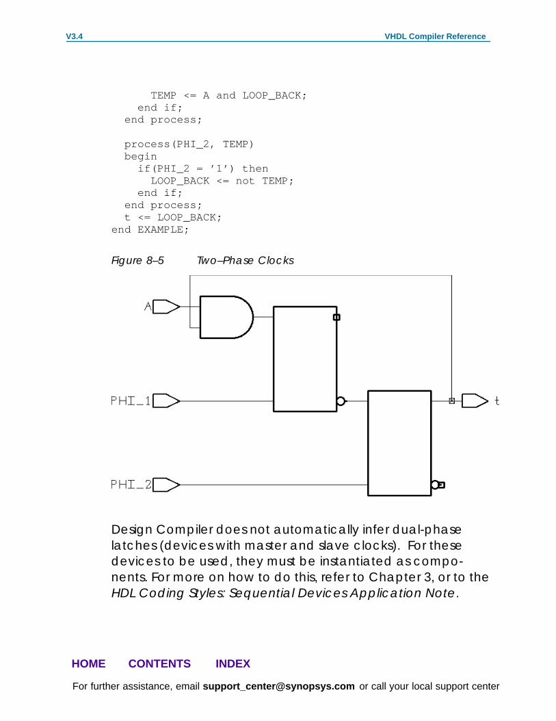
Example—Design with Two-Phase ClocksThe latch inference capability permits network structures suchas two-phase systems to be described in a technology-inde-pendent manner. Example 8–6 shows a simple two-phasesystem with clocks PHI_1 and PHI_2 .
Example 8–6 Two–Phase Clocks
entity LATCH_VHDL is port(PHI_1, PHI_2, A : in STD_LOGIC; t: out STD_LOGIC);end LATCH_VHDL;
architecture EXAMPLE of LATCH_VHDL is signal TEMP, LOOP_BACK: STD_LOGIC;begin process(PHI_1, A, LOOP_BACK) begin if(PHI_1 = ’1’) then
VHDL Compiler Reference V3.4
For further assistance, email [email protected] or call your local support center
HOME CONTENTS INDEX
TEMP <= A and LOOP_BACK; end if; end process;
process(PHI_2, TEMP) begin if(PHI_2 = ’1’) then LOOP_BACK <= not TEMP; end if; end process; t <= LOOP_BACK;end EXAMPLE;
Figure 8–5 Two–Phase Clocks
Design Compiler does not automatically infer dual-phaselatches (devices with master and slave clocks). For thesedevices to be used, they must be instantiated as compo-nents. For more on how to do this, refer to Chapter 3, or to theHDL Coding Styles: Sequential Devices Application Note.

VHDL Compiler Reference V3.4
For further assistance, email [email protected] or call your local support center
HOME CONTENTS INDEX
Describing Flip-flopsExample 8–7 shows how an edge construct creates a flip-flop.
Example 8–7 Inferred Flip-flop
process(CLK, DATA)begin if (CLK’event and CLK = ’1’) then Q <= DATA; end if;end process;
Figure 8–6 Inferred Flip-flop

VHDL Compiler Reference V3.4
For further assistance, email [email protected] or call your local support center
HOME CONTENTS INDEX
Flip-flop with Asynchronous ResetExample 8–8 shows how to specify a flip-flop with an asynch-ronous reset.
Example 8–8 Inferred Flip-flop with Asynchronous Reset
process(RESET_LOW, CLK, SYNC_DATA)begin if RESET_LOW = ’0’ then Q <= ’0’; elsif (CLK’event and CLK = ’1’) then Q <= SYNC_DATA; end if;end process;
Figure 8–7 Inferred Flip-flop with Asynchronous Reset
Note how the flip-flop in Example 8–8 is connected.
� The D input of the flip-flop is connected to SYNC_DATA.
� If the reset condition is computable (see “ComputableOperands” in Chapter 5), either the SET or CLEAR pin ofthe flip-flop is connected to the RESET_LOW signal, asshown in Example 8–8.

VHDL Compiler Reference V3.4
For further assistance, email [email protected] or call your local support center
HOME CONTENTS INDEX
Example 8–9 shows an inferred flip-flop with an asynchronousreset, where the reset condition is not computable.
If the reset condition (ANY_SIGNAL in Example 8–9) is not com-putable, SET is connected to (ANY_SIGNAL AND ASYNC_DATA)
and CLEAR is connected to (ANY_SIGNAL AND NOT(ASYNC_DATA)) ,as shown in Example 8–9.
Example 8–9 Inferred Flip-flop with Asynchronous Set or Clear
process (CLK, ANY_SIGNAL, ASYNC_DATA, SYNC_DATA) begin if (ANY_SIGNAL) then Q <= ASYNC_DATA; elsif (CLK’event and CLK = ’1’) then Q <= SYNC_DATA; end if; end process;
Figure 8–8 Inferred Flip-flop with Asynchronous Set or Clear

VHDL Compiler Reference V3.4
For further assistance, email [email protected] or call your local support center
HOME CONTENTS INDEX
Example—Synchronous Design with Asynchronous ResetExample 8–10 describes a synchronous finite state machinewith an asynchronous reset.
Example 8–10 Synchronous Finite State Machine with AsynchronousReset
package MY_TYPES is type STATE_TYPE is (S0, S1, S2, S3);end MY_TYPES;
use WORK.MY_TYPES.ALL;
entity STATE_MACHINE is port(CLK, INC, A, B: in STD_LOGIC; RESET: in BOOLEAN; t: out STD_LOGIC);end STATE_MACHINE;
architecture EXAMPLE of STATE_MACHINE is signal CURRENT_STATE, NEXT_STATE: STATE_TYPE;begin SYNC: process(CLK, RESET) begin if (RESET) then CURRENT_STATE <= S0; elsif (CLK’event and CLK = ’1’) then CURRENT_STATE <= NEXT_STATE; end if; end process SYNC;
FSM: process(CURRENT_STATE, A, B) begin t <= A; –– Default assignment NEXT_STATE <= S0; –– Default assignment
if (INC = ’1’) then case CURRENT_STATE is when S0 => NEXT_STATE <= S1; when S1 => NEXT_STATE <= S2; t <= B; when S2 => NEXT_STATE <= S3;

VHDL Compiler Reference V3.4
For further assistance, email [email protected] or call your local support center
HOME CONTENTS INDEX
when S3 => null; end case; end if; end process FSM;end EXAMPLE;
Figure 8–9 Synchronous Finite State Machine with Asynchronous Reset
B
A
CLK
INC
RESET
t

VHDL Compiler Reference V3.4
For further assistance, email [email protected] or call your local support center
HOME CONTENTS INDEX
Additional Types of Register InferenceFor examples of various type of latches and flip-flops that usethe attributes and variables introduced in the followingsections, see the HDL Coding Styles: Sequential DevicesApplication Note.
AttributesThis section discusses attributes used to assist register infer-ence. The attributes are defined in the “attributes” packagein the VHDL library called Synopsys .
attribute async_set_reset : string;attribute sync_set_reset : string;attribute async_set_reset_local : string;attribute sync_set_reset_local : string;attribute async_set_reset_local_all : string;attribute sync_set_reset_local_all : string;attribute one_hot : string;attribute one_cold : string;
async_set_reset
async_set_reset is attached to single–bit signals using theattribute construct. VHDL Compiler checks signals with theasync_set_reset attribute set to true to determine whetherthey asynchronously set or reset a latch or flip–flop in theentire design.
The syntax of async_set_reset is
attribute async_set_reset of signal_name,. : signal is “true”;
Latch with Asynchronous Set or ClearThe asynchronous clear (or set) is inferred by driving the ”Q”pin of your latch to 0 (1). Although VHDL Compiler does notrequire that the clear (or set) be the first condition in yourconditional branch, it is best to write your VHDL in that man-ner.

VHDL Compiler Reference V3.4
For further assistance, email [email protected] or call your local support center
HOME CONTENTS INDEX
Example 8–11 shows how to specify a latch with an asynchro-nous clear.
Example 8–11 Inferred Latch with Asynchronous Clear
attribute async_set_reset of clear : signal is “true”;process(clear, gate, a)begin if ( clear = ’1’ ) then q <= ’0’ ; elsif (gate = ’1’) then q <= a; end if;end process;
Figure 8–10 Inferred Latch with Asynchronous Clear

VHDL Compiler Reference V3.4
For further assistance, email [email protected] or call your local support center
HOME CONTENTS INDEX
sync_set_reset
sync_set_reset is attached to single-bit signals using theattribute constructs. VHDL Compiler checks signals with thesync_set_reset attribute set to true to determine whetherthey synchronously set or reset a flip-flop in the entire design.
The syntax of sync_set_reset is
attribute sync_set_reset of signal_name,... : signal is “true”;
Flip-flop with Synchronous ResetExample 8–12 shows how to specify a flip-flop with a synchro-nous reset.
Example 8–12 Inferred Flip–flop with Synchronous Reset
attribute sync_set_reset of RESET : signal is “true”;process(RESET, CLK)begin if (CLK’event and CLK = ’1’) then if RESET = ’1’ then Q <= ’0’; else Q <= DATA_A; end if; end if;end process;
Figure 8–11 Inferred Flip-flop with Synchronous Reset

VHDL Compiler Reference V3.4
For further assistance, email [email protected] or call your local support center
HOME CONTENTS INDEX
Note:Since the target technology library did not contain asynchronous reset flip–flop, Design Compiler built thesynchronous reset conditions using combinational logic.
Flip–Flop with Synchronous SetExample 8–13 shows how to specify a flip-flop with a synchro-nous set.
Example 8–13 Inferred Flip–Flop with Synchronous Set
attribute sync_set_reset of SET : signal is “true”process (SET, CLK)begin if (CLK’event and CLK = ’1’) then if SET = ’1’ then T <= ’1’; else T <= DATA_B; end if; end if;end process;
Figure 8–12 Inferred Flip–Flop with Synchronous Set
Note:Since the target technology library did not contain asynchronous set flip–flop, Design Compiler built thesynchronous set conditions using combinational logic.

VHDL Compiler Reference V3.4
For further assistance, email [email protected] or call your local support center
HOME CONTENTS INDEX
async_set_reset_local
async_set_reset_local is attached to the label of a processwith a value of a double-quoted list of single-bit signals. Everysignal in the list is treated as if it has the async_set_reset
attribute attached in the specified process.
The syntax of async_set_reset_local is
attribute async_set_reset_local of process_label : label is “signal_name,...”;
Example 8–14 Asynchronous Set/Reset on a Single Block
library IEEE;library synopsys;use IEEE.std_logic_1164.all;use synopsys.attributes.all;
entity e_async_set_reset_local isport(reset, set, gate: in std_logic; y, t: out std_logic);end e_async_set_reset_local;
architecture rtl of e_async_set_reset_local isattribute async_set_reset_local of direct_set_reset : label
is “reset, set”;begin
direct_set_reset: process (reset, set) begin if (reset = ’1’) then y <= ’0’; –– asynchronous reset elsif (set = ’1’) then y <= ’1’; –– asynchronous set end if; end process direct_set_reset;

VHDL Compiler Reference V3.4
For further assistance, email [email protected] or call your local support center
HOME CONTENTS INDEX
gated_set_reset: process (gate, reset, set) begin if (gate = ’1’) then if (reset = ’1’) then t <= ’0’; –– gated data elsif (set = ’1’) then t <= ’1’; –– gated data end if; end if; end process gated_set_reset;
end rtl;
Figure 8–13 Asynchronous Set/Reset on a Single Block

VHDL Compiler Reference V3.4
For further assistance, email [email protected] or call your local support center
HOME CONTENTS INDEX
sync_set_reset_local
sync_set_reset_local is attached to the label of a processwith a value of a double–quoted list of single–bit signals.Every signal in the list is treated as if it has the sync_set_reset
attribute attached in the specified process.
The syntax of sync_set_reset_local is
attribute sync_set_reset_local of process_label : label is“signal_name,...”
Example 8–15 Synchronous Set/Reset on a Single Block
library IEEE;library synopsys;use IEEE.std_logic_1164.all;use synopsys.attributes.all;
entity e_sync_set_reset_local isport(clk, reset, set, gate : in std_logic; y, t: out std_logic);end e_sync_set_reset_local;
architecture rtl of e_sync_set_reset_local isattribute sync_set_reset_local of clocked_set_reset : label is“reset, set”;begin
clocked_set_reset: process (clk, reset, set) begin if (clk’event and clk = ’1’) then if (reset = ’1’) then y <= ’0’; –– synchronous reset else y <= ’1’; –– synchronous set end if; end if; end process clocked_set_reset;
gated_set_reset: process (clk, gate, reset, set) begin if (clk’event and clk = ’1’) then if (gate = ’1’) then if (reset = ’1’) then t <= ’0’; –– gated reset elsif (set = ’1’) then

VHDL Compiler Reference V3.4
For further assistance, email [email protected] or call your local support center
HOME CONTENTS INDEX
t <= ’1’; –– gated set end if; end if; end if; end process gated_set_reset;
end rtl;
Figure 8–14 Synchronous Set/Reset on a Single Block
z
y
set
d2
reset
clk
d1
Note:Since the target technology library did not contain asynchronous set or a synchronous reset flip–flop, DesignCompiler built the synchronous set/reset conditions usingcombinational logic.

VHDL Compiler Reference V3.4
For further assistance, email [email protected] or call your local support center
HOME CONTENTS INDEX
async_set_reset_local_all
async_set_reset_local_all is attached to a process label. Theattribute async_set_reset_local_all specifies that all thesignals in the process are used to detect an asynchronous setor reset condition for inferred latches or flip-flops.
The syntax of async_set_reset_local_all is
attribute async_set_reset_local_all of process_label,... : label is“true”;
Example 8–16 Asynchronous Set/Reset on Part of a Design
library IEEE;library synopsys;use IEEE.std_logic_1164.all;use synopsys.attributes.all;
entity e_async_set_reset_local_all isport(reset, set, gate, gate2: in std_logic; y, t, w: out std_logic);end e_async_set_reset_local_all;architecture rtl of e_async_set_reset_local_all isattribute async_set_reset_local_all of direct_set_reset, direct_set_reset_too: label is “true”;begin direct_set_reset: process (reset, set) begin if (reset = ’1’) then y <= ’0’; –– asynchronous reset elsif (set = ’1’) then y <= ’1’; –– asynchronous set end if; end process direct_set_reset; direct_set_reset_too: process (gate, reset, set) begin if (gate = ’1’) then if (reset = ’1’) then t <= ’0’; –– asynchronous reset elsif (set = ’1’) then t <= ’1’; –– asynchronous set end if; end if; end process direct_set_reset_too;

VHDL Compiler Reference V3.4
For further assistance, email [email protected] or call your local support center
HOME CONTENTS INDEX
gated_set_reset: process (gate2, reset, set) begin if (gate2 = ’1’) then if (reset = ’1’) then w <= ’0’; –– gated reset elsif (set = ’1’) then w <= ’1’; –– gated set end if; end if; end process gated_set_reset;end rtl;
Figure 8–15 Asynchronous Set/Reset on Part of a Design

VHDL Compiler Reference V3.4
For further assistance, email [email protected] or call your local support center
HOME CONTENTS INDEX
sync_set_reset_local_all
sync_set_reset_local_all is attached to a process label. Theattribute sync_set_reset_local_all specifies that all thesignals in the process are used to detect a synchronous set orreset condition for inferred latches or flip–flops.
The syntax of sync_set_reset_local_all is attribute
sync_set_reset_local_all of process_label,... : label is “true”;
Example 8–17 Synchronous Set/Reset on a Part of a Design
library IEEE;library synopsys;use IEEE.std_logic_1164.all;use synopsys.attributes.all;
entity e_sync_set_reset_local_all isport(clk, reset, set, gate, gate2: in std_logic; y, t, w: out std_logic);end e_sync_set_reset_local_all;
architecture rtl of e_sync_set_reset_local_all isattribute sync_set_reset_local_all of clocked_set_reset, clocked_set_reset_too: label is “true”;begin
clocked_set_reset: process (clk, reset, set) begin if (clk’event and clk = ’1’) then if (reset = ’1’) then y <= ’0’; –– synchronous reset elsif (set = ’1’) then y <= ’1’; –– synchronous set end if; end if; end process clocked_set_reset;

VHDL Compiler Reference V3.4
For further assistance, email [email protected] or call your local support center
HOME CONTENTS INDEX
clocked_set_reset_too: process (clk, gate, reset, set) begin if (clk’event and clk = ’1’) then if (gate = ’1’) then if (reset = ’1’) then t <= ’0’; –– synchronous reset elsif (set = ’1’) then t <= ’1’; –– synchronous set end if; end if; end if; end process clocked_set_reset_too;
gated_set_reset: process (gate2, reset, set) begin if (gate2 = ’1’) then if (reset = ’1’) then w <= ’0’; –– gated reset elsif (set = ’1’) then w <= ’1’; –– gated set end if; end if; end process gated_set_reset;
end rtl;

VHDL Compiler Reference V3.4
For further assistance, email [email protected] or call your local support center
HOME CONTENTS INDEX
Figure 8–16 Synchronous Set/Reset on a Part of a Design
Note:Since the target technology library did not contain asynchronous set or a synchronous reset flip–flop, DesignCompiler built the synchronous set/reset conditions usingcombinational logic.
VHDL Compiler Reference V3.4
For further assistance, email [email protected] or call your local support center
HOME CONTENTS INDEX
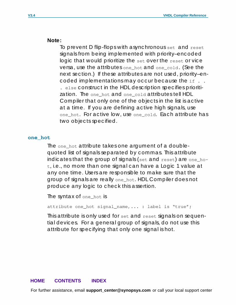
Note:To prevent D flip-flops with asynchronous set and reset
signals from being implemented with priority–encodedlogic that would prioritize the set over the reset or viceversa, use the attributes one_hot and one_cold. (See thenext section.) If these attributes are not used, priority–en-coded implementations may occur because the if . .. else construct in the HDL description specifies prioriti-zation. The one_hot and one_cold attributes tell HDLCompiler that only one of the objects in the list is activeat a time. If you are defining active high signals, useone_hot . For active low, use one_cold . Each attribute hastwo objects specified.
one_hot
The one_hot attribute takes one argument of a double-quoted list of signals separated by commas. This attributeindicates that the group of signals (set and reset ) are one_ho-
t , i.e., no more than one signal can have a Logic 1 value atany one time. Users are responsible to make sure that thegroup of signals are really one_hot . HDL Compiler does notproduce any logic to check this assertion.
The syntax of one_hot is
attribute one_hot signal_name,... : label is “true”;
This attribute is only used for set and reset signals on sequen-tial devices. For a general group of signals, do not use thisattribute for specifying that only one signal is hot.

VHDL Compiler Reference V3.4
For further assistance, email [email protected] or call your local support center
HOME CONTENTS INDEX
Example 8–18 Using one_hot for Set and Reset
library IEEE;library synopsys;use IEEE.std_logic_1164.all;use synopsys.attributes.all;
entity e_one_hot isport(reset, set, reset2, set2: in std_logic; y, t: out std_logic);attribute async_set_reset of reset, set : signal is “true”;attribute async_set_reset of reset2, set2 : signal is “true”;attribute one_hot of reset, set : signal is “true”;end e_one_hot;
architecture rtl of e_one_hot isbegin direct_set_reset: process (reset, set ) begin if (reset = ’1’) then y <= ’0’; –– asynchronous reset by “reset” elsif (set = ’1’) then y <= ’1’; –– asynchronous set by “set” end if; end process direct_set_reset; direct_set_reset_too: process (reset2, set2 ) begin if (reset2 = ’1’) then t <= ’0’; –– asynchronous reset by “reset2” elsif (set2 = ’1’) then t <= ’1’; –– asynchronous set by “~reset2 set2” end if; end process direct_set_reset_too;–– synopsys synthesis_offprocess (reset, set)begin assert not (reset=’1’ and set=’1’) report “One–hot violation” severity Error;end process;–– synopsys synthesis_onend rtl;

VHDL Compiler Reference V3.4
For further assistance, email [email protected] or call your local support center
HOME CONTENTS INDEX
Figure 8–17 shows the schematic generated by the code inExample 8–18.
Figure 8–17 Using one_hot for Set and Reset

VHDL Compiler Reference V3.4
For further assistance, email [email protected] or call your local support center
HOME CONTENTS INDEX
one_cold
The one_cold attribute takes one argument of a double-quoted list of signals separated by commas. This attributeindicates that the group of signals (set and reset ) is one_cold ,i.e., no more than one signal can have a Logic 0 value at anyone time. Users are responsible to make sure that the groupof signals is really one_cold . VHDL Compiler does not produceany logic to check this assertion.
The syntax of one_hot is
attribute one_cold signal_name,... : label is “true”;
This attribute is only used for set and reset signals on se-quential devices. For a general group of signals, do not usethis attribute to specify that only one signal is cold.
Example 8–19 Using one_cold for Set and Reset
library IEEE;library synopsys;use IEEE.std_logic_1164.all;use synopsys.attributes.all;entity e_one_cold isport(reset, set, reset2, set2: in std_logic; y, t: out std_logic);attribute async_set_reset of reset, set : signal is “true”;attribute async_set_reset of reset2, set2 : signal is “true”;attribute one_cold of reset, set : signal is “true”;end e_one_cold;
architecture rtl of e_one_cold isbegin
direct_set_reset: process (reset, set ) begin if (reset = ’0’) then y <= ’0’; –– asynchronous reset by “not reset” elsif (set = ’0’) then y <= ’1’; –– asynchronous set by “not set” end if; end process direct_set_reset;

VHDL Compiler Reference V3.4
For further assistance, email [email protected] or call your local support center
HOME CONTENTS INDEX
direct_set_reset_too: process (reset2, set2 ) begin if (reset2 = ’0’) then t <= ’0’; –– asynchronous reset by “not reset2” elsif (set2 = ’0’) then t <= ’1’; –– asynchronous set by “(not reset2) (not set2)” end if; end process direct_set_reset_too;
–– synopsys synthesis_offprocess (reset, set)begin assert not (reset=’0’ and set=’0’) report “One–cold violation” severity Error;end process;–– synopsys synthesis_on
end rtl;
Figure 8–18 Using one_cold for Set and Reset

VHDL Compiler Reference V3.4
For further assistance, email [email protected] or call your local support center
HOME CONTENTS INDEX
dc_shell Variables for Latch or Flip-flop InferenceThe following dc_shell variables control latch or flip-flopinference.
hdlin_ff_always_async_set_reset
By default, hdlin_ff_always_async_set_reset is true . VHDLCompiler does not report an asynchronous set or reset condi-tion of flip–flops unless you set this variable to true .
Since the default setting for this variable is true , VHDL Compil-er automatically checks for set and reset conditions offlip–flops.
hdlin_ff_always_sync_set_reset
For a design analyzed subsequently by VHDL Compiler, ifhdlin_ff_always_sync_set_reset is true , every signal in thedesign is regarded as if it has the sync_set_reset attributeattached. The default setting of hdlin_ff_al-
ways_sync_set_reset is false .
hdlin_latch_always_async_set_reset
By default, hdlin_latch_always_async_set_reset is true. Afalse setting causes VHDL Compiler to interpret each controlobject of a latch as synchronous. If you want to asynchro-nously set or reset a latch, set this variable to true .
Setting the variable to true is equivalent to specifying everyobject in the design as the object list for the async_set_reset
directive. When true , for a design subsequently analyzed,every constant 0 loaded on a latch is used for asynchronousreset, and every constant 1 loaded on a latch is used forasynchronous set. VHDL Compiler does not limit checks forassignments to a constant 0 or constant 1 to a single process.That is, VHDL Compiler performs checking across processes.

VHDL Compiler Reference V3.4
For further assistance, email [email protected] or call your local support center
HOME CONTENTS INDEX
hdlin_keep_feedbackBy default, hdlin_keep_feedback is false . A false settingcauses VHDL Compiler to remove all flip-flop feedback loops.For example, feedback loops inferred from a statement suchas Q=Q are removed. With the state feedback removed froma simple D flip-flop, it becomes a synchronous loaded flip-flop. Set the hdlin_keep_feedback variable to true if you wantto keep feedback loops.
hdlin_keep_inv_feedbackBy default, hdlin_keep_inv_feedback is true . It should be set tofalse before HDL input if you want to infer toggle or JK flip–flops.
A false value causes VHDL Compiler to remove all invertedflip-flop feedback loops. For example, feedback loops in-ferred from a statement such as Q=Q are removed and synthe-sized as T flip-flops. Set the hdlin_keep_inv_feedback variableto true if you want to keep inverted feedback loops.
hdlin_check_no_latchIf hdlin_check_no_latch is set true and latches are inferredfrom a design, VHDL Compiler reports a design warning. Thedefault setting of hdlin_check_no_latch is false . This is usefulfor verifying that a combinational design does not containmemory components.
hdlin_report_inferred_modulesPossible values for hdlin_report_inferred_modules are true , false , and verbose . When false , VHDL Compiler does notreport information on inferred latches, flip-flops, or three-stategates. When true , a brief report is generated for these in-ferred devices.

VHDL Compiler Reference V3.4
For further assistance, email [email protected] or call your local support center
HOME CONTENTS INDEX
When verbose , detailed information also is reported. Theseinclude the asynchronous set or reset, synchronous set orreset, and synchronous toggle conditions of each latch orflip-flop expressed in Boolean formulas. The default setting ofhdlin_report_inferred_modules is true .
Example 8–20 Bus Latch
library IEEE;library synopsys;use IEEE.std_logic_1164.all;use synopsys.attributes.all;
entity e_bus_latch isport(reset, set, gate: in std_logic; d: in std_logic_vector(1 downto 0); y: out std_logic_vector(1 downto 0));attribute async_set_reset of reset, set : signal is “true”;end e_bus_latch;
architecture rtl of e_bus_latch isbegin
bus_assignment: process (reset, set, gate) begin if (reset = ’1’) then y <= “00”; elsif (set = ’1’) then y <= “11”; elsif (gate = ’1’) then y <= d; end if; end process bus_assignment;
end rtl;
With hdlin_report_inferred_modules set to verbose ,Example 8–20 generates the output shown in the table inExample 8–21. In the table, AR stands for Asynchronous-Reset,AS stands for Asynchronous-Set, SR stands for Synchronous-Re-set, SS stands for Synchronous-Set, and ST stands for Synchro-nous-Toggle.

VHDL Compiler Reference V3.4
For further assistance, email [email protected] or call your local support center
HOME CONTENTS INDEX
Since latches do not have Synchronous-Reset/Set/Toggle, theSR, SS, and ST columns are marked “–” (for N/A). The “Y” markin the AR and AS columns indicates that the latches inferreduse Asynchronous-Reset and Asynchronous-Set pins. The Buscolumn is marked “Y” to indicate y_reg is a bus latch.
A table like this is generated when hdlin_report_in-
ferred_modules is set to true or verbose . A detailed report likethe one following the table is generated only when hdlin_re-
port_inferred_modules is set to verbose . The report shows thatall cells in the bus latch are asynchronously reset by the signalreset , and are asynchronously set by the signal set .
The last line in the report, “Async–set and Async–reset ==> Q:
0” indicates that when both reset and set are Logic 1, theoutput of the latch is Logic 0. If Design Compiler finds a latchcell in the target library that has the same property (i.e.,output is Logic 0 when clear and preset are both active), thesignal reset is connected directly to the clear pin and thesignal set is connected directly to the preset pin.
However, if no such latch is found in the target library, DesignCompiler synthesizes an AND function (~reset and set ) toprioritize reset over set and connect it to the preset pin, whilethe signal reset still connects directly to the clear pin.
Example 8–21 Bus Latch Report
Inferred memory devices in process in routine bus_latch line 11 in file ’bus_latch.vhd’.==========================================================================| Register Name | Type | Width | Bus | AR | AS | SR | SS | ST |==========================================================================| y_reg | Latch | 2 | Y | Y | Y | – | – | – |==========================================================================
y_reg (width 2)–––––––––––––––

VHDL Compiler Reference V3.4
For further assistance, email [email protected] or call your local support center
HOME CONTENTS INDEX
Async–reset: reset Async–set: set Async–set and Async–reset ==> Q: 0
Latch with Asynchronous Set and ResetExample 8–22 demonstrates how to eliminate the prioritizationin Example 8–20 by using the one_hot attribute. This attributegives Design Compiler more freedom to choose a map forthe latch. one_hot indicates a dont-care condition when bothreset and set are Logic 1. Note the difference in the last linesof the detailed reports shown in Example 8–23 andExample 8–21.
Example 8–22 Bus Latch with one_hot
library IEEE;library synopsys;use IEEE.std_logic_1164.all;use synopsys.attributes.all;
entity e_bus_latch_with_one_hot isport(reset, set, gate: in std_logic; d: in std_logic_vector(1 downto 0); y: out std_logic_vector(1 downto 0));attribute async_set_reset of reset, set : signal is “true”;attribute one_hot of reset, set : signal is “true”;end e_bus_latch_with_one_hot;
architecture rtl of e_bus_latch_with_one_hot isbegin

VHDL Compiler Reference V3.4
For further assistance, email [email protected] or call your local support center
HOME CONTENTS INDEX
bus_with_one_hot: process (reset, set, gate) begin if (reset = ’1’) then y <= “00”; elsif (set = ’1’) then y <= “11”; elsif (gate = ’1’) then y <= d; end if; end process bus_with_one_hot;
–– synopsys synthesis_offprocess (reset, set)begin assert not (reset=’1’ and set=’1’) report “One–hot violation” severity Error;end process;–– synopsys synthesis_on
end rtl;
Example 8–23 Bus Latch with one_hot Report
Inferred memory devices in process in routine bus_latch_with_one_hot line 12 in file ’bus_latch_with_one_hot.vhd’.==========================================================================| Register Name | Type | Width | Bus | AR | AS | SR | SS | ST |==========================================================================| y_reg | Latch | 2 | Y | Y | Y | – | – | – |==========================================================================
y_reg (width 2)––––––––––––––– Async–reset: reset Async–set: set Async–set and Async–reset ==> Q: X
VHDL Compiler Reference V3.4
For further assistance, email [email protected] or call your local support center
HOME CONTENTS INDEX
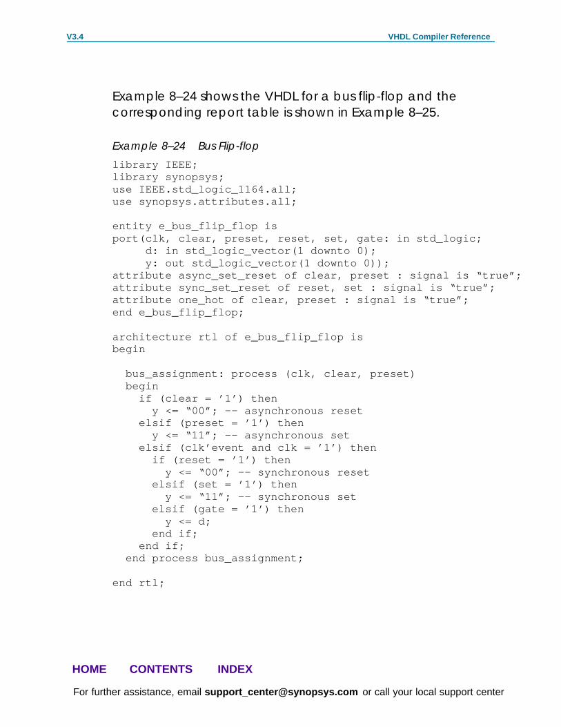
Example 8–24 shows the VHDL for a bus flip-flop and thecorresponding report table is shown in Example 8–25.
Example 8–24 Bus Flip-flop
library IEEE;library synopsys;use IEEE.std_logic_1164.all;use synopsys.attributes.all;
entity e_bus_flip_flop isport(clk, clear, preset, reset, set, gate: in std_logic; d: in std_logic_vector(1 downto 0); y: out std_logic_vector(1 downto 0));attribute async_set_reset of clear, preset : signal is “true”;attribute sync_set_reset of reset, set : signal is “true”;attribute one_hot of clear, preset : signal is “true”;end e_bus_flip_flop;
architecture rtl of e_bus_flip_flop isbegin
bus_assignment: process (clk, clear, preset) begin if (clear = ’1’) then y <= “00”; –– asynchronous reset elsif (preset = ’1’) then y <= “11”; –– asynchronous set elsif (clk’event and clk = ’1’) then if (reset = ’1’) then y <= “00”; –– synchronous reset elsif (set = ’1’) then y <= “11”; –– synchronous set elsif (gate = ’1’) then y <= d; end if; end if; end process bus_assignment;
end rtl;

VHDL Compiler Reference V3.4
For further assistance, email [email protected] or call your local support center
HOME CONTENTS INDEX
Example 8–25 Bus Flip-flop Report
Inferred memory devices in process ’bus’ in routine bus_latch line 13 in file ’bus_latch.vhd’.==========================================================================| Register Name | Type | Width | Bus | AR | AS | SR | SS | ST |==========================================================================| y_reg | Flip–flop | 2 | Y | Y | Y | Y | Y | N |==========================================================================
y_reg (width 2)––––––––––––––– Async–reset: clear Async–set: preset Sync–reset: reset Sync–set: set Async–set and Async–reset ==> Q: X Sync–set and Sync–reset ==> Q: 0
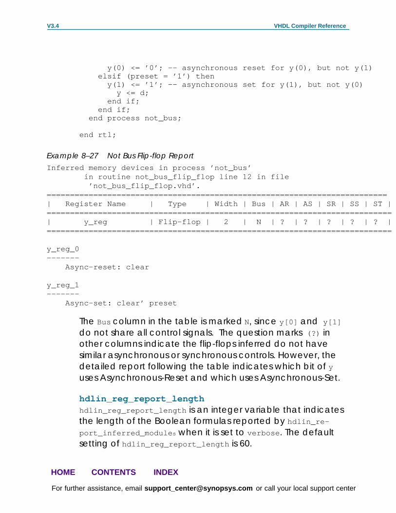
Example 8–26 and Example 8–27 show the VHDL and detailedreport produced when multiple-bit data do not infer a busflip-flop.
Example 8–26 Not Bus Flip-flop
library IEEE;library synopsys;use IEEE.std_logic_1164.all;use synopsys.attributes.all;
entity e_not_bus_flip_flop isport(clk, clear, preset : in std_logic; d: in std_logic_vector(0 to 1); y: out std_logic_vector(0 to 1));attribute async_set_reset of clear, preset : signal is “true”;end e_not_bus_flip_flop;
architecture rtl of e_not_bus_flip_flop isbegin
not_bus: process (clk, clear, preset) begin if (clear = ’1’) then
VHDL Compiler Reference V3.4
For further assistance, email [email protected] or call your local support center
HOME CONTENTS INDEX
y(0) <= ’0’; –– asynchronous reset for y(0), but not y(1) elsif (preset = ’1’) then y(1) <= ’1’; –– asynchronous set for y(1), but not y(0) y <= d; end if; end if; end process not_bus;
end rtl;
Example 8–27 Not Bus Flip-flop Report
Inferred memory devices in process ’not_bus’ in routine not_bus_flip_flop line 12 in file ’not_bus_flip_flop.vhd’.=========================================================================| Register Name | Type | Width | Bus | AR | AS | SR | SS | ST |==========================================================================| y_reg | Flip–flop | 2 | N | ? | ? | ? | ? | ? |==========================================================================
y_reg_0––––––– Async–reset: clear
y_reg_1––––––– Async–set: clear’ preset
The Bus column in the table is marked N, since y[0] and y[1]
do not share all control signals. The question marks (?) inother columns indicate the flip-flops inferred do not havesimilar asynchronous or synchronous controls. However, thedetailed report following the table indicates which bit of yuses Asynchronous-Reset and which uses Asynchronous-Set.
hdlin_reg_report_lengthhdlin_reg_report_length is an integer variable that indicatesthe length of the Boolean formulas reported by hdlin_re-
port_inferred_module s when it is set to verbose . The defaultsetting of hdlin_reg_report_length is 60.

VHDL Compiler Reference V3.4
For further assistance, email [email protected] or call your local support center
HOME CONTENTS INDEX
Efficient Use of RegistersHDL descriptions should build only as many flip-flops as adesign requires. Example 8–28 shows a description where toomany flip-flops are implied.
Example 8–28 Circuit with Six Implied Registers
library IEEE;use IEEE.std_logic_1164.all;use IEEE.std_logic_unsigned.all;
entity ex8_13 isport ( clk , reset : in std_logic; and_bits , or_bits , xor_bits : out std_logic);end ex8_13;
architecture rtl of ex8_13 isbeginprocessvariable count : std_logic_vector (2 downto 0);begin wait until (clk’event and clk = ’1’); if (reset = ’1’) then count := “000”; else count := count + 1; end if; and_bits <= count(2) and count(1) and count(0); or_bits <= count(2) or count(1) or count(0); xor_bits <= count(2) xor count(1) xor count(0);end process;end rtl;

VHDL Compiler Reference V3.4
For further assistance, email [email protected] or call your local support center
HOME CONTENTS INDEX
Figure 8–19 Circuit with Six Implied Registers
OR_BITS
AND_BITS
RESET
CLOCK
XOR_BITS
In Example 8–28, the outputs AND_BITS, OR_BITS, and XOR_BITS
depend solely on the value of COUNT. Since COUNT is registered,the three outputs do not need to be registered. To avoidimplying extra registers, assign the outputs from within aprocess that does not have a wait statement. Example 8–29shows a description with two processes, one with a wait
statement and one without. This description style lets youchoose the signals that are registered and those that are not.

VHDL Compiler Reference V3.4
For further assistance, email [email protected] or call your local support center
HOME CONTENTS INDEX
Example 8–29 Circuit with Three Implied Registers
library IEEE;use IEEE.std_logic_1164.all;use IEEE.std_logic_unsigned.all;
entity COUNT is port(CLOCK, RESET: in std_logic; AND_BITS, OR_BITS, XOR_BITS : out std_logic);
end COUNT;
architecture RTL of COUNT is signal COUNT : UNSIGNED (2 downto 0);begin
REG: process –– Registered logic begin wait until CLOCK’event and CLOCK = ’1’; if (RESET = ’1’) then COUNT <= ”000”; else COUNT <= COUNT + 1; end if; end process;
COMBIN: process(COUNT) –– Combinational logic begin AND_BITS <= COUNT(2) and COUNT(1) and COUNT(0); OR_BITS <= COUNT(2) or COUNT(1) or COUNT(0); XOR_BITS <= COUNT(2) xor COUNT(1) xor COUNT(0); end process;end RTL;

VHDL Compiler Reference V3.4
For further assistance, email [email protected] or call your local support center
HOME CONTENTS INDEX
Figure 8–20 Circuit with Three Implied Registers
CLOCK
RESET
The technique of separating combinational logic from regis-tered or sequential logic is useful when describing finite statemachines.
See the following examples in Appendix A:
� Moore Machine
� Mealy Machine
� Count Zeros — Sequential Version
� Soft Drink Machine Controller — State Machine Version

VHDL Compiler Reference V3.4
For further assistance, email [email protected] or call your local support center
HOME CONTENTS INDEX
Example—Using Synchronous and Asynchronous ProcessesThere may be occasions when you want to keep some of thevalues computed by a process in flip-flops, while allowingother values to change between clock edges. This can bedone by splitting your algorithm between two processes, onewith a wait statement and one without. Put the registered(synchronous) assignments into the wait process. Put theother (asynchronous) assignments in the other process. Usesignals to communicate between the two processes.
For example, suppose you want to build a design with thefollowing characteristics:
� Inputs A_1, A_2, A_3 and A_4 change asynchronously.
� Output t is driven from one of A_1, A_2, A_3, or A_4.
� Input CONTROL is valid only on the positive edge of CLOCK.The value at the edge determines which of the fourinputs is selected during the next clock cycle.
� Output t must always reflect changes in the value of thecurrently selected signal.
The implementation of this design requires two processes. Thewait statement process synchronizes the CONTROL value. Theother process multiplexes the output based on the synchro-nized control. The signal SYNC_CONTROL communicates be-tween the two processes. Example 8–30 shows the code anda schematic of one possible implementation.
Example 8–30 Two Processes: One Synchronous, One Asynchronous
entity SYNC_ASYNC is port (CLOCK: in STD_LOGIC; CONTROL: in INTEGER range 0 to 3; A: in BIT_VECTOR(0 to 3); t: out STD_LOGIC);end SYNC_ASYNC;architecture EXAMPLE of SYNC_ASYNC is

VHDL Compiler Reference V3.4
For further assistance, email [email protected] or call your local support center
HOME CONTENTS INDEX
signal SYNC_CONTROL: INTEGER range 0 to 3;begin process begin wait until CLOCK’event and CLOCK = ’1’; SYNC_CONTROL <= CONTROL; end process; process (A, SYNC_CONTROL) begin t <= A(SYNC_CONTROL); end process;end EXAMPLE;
Figure 8–21 Two Processes: One Synchronous, One Asynchronous

VHDL Compiler Reference V3.4
For further assistance, email [email protected] or call your local support center
HOME CONTENTS INDEX
MultiplexersMultiplexers or MUXes are widely used by hardware designersto implement conditional assignments to signals.
In Version 3.4a, VHDL Compiler improves the way multiplexersare inferred. Users can embed an attribute in the VHDL, or usevariables to tell VHDL Compiler that case statements in certainprocesses of the VHDL code should be inferred as genericmultiplexer cells called MUX_OPs. Design Compiler thenattempts to map MUX_OPs in the design to multiplexer cells inthe target technology library.
Similar to Synopsys DesignWare components, MUX_OPs arehierarchical cells whose implementation is determined byDesign Compiler during compile.
Note:In order to use the multiplexer inferencing feature, thetarget technology library must contain at least a 2–to–1multiplexer.
See the Optimizing Design chapter of The Design CompilerFamily Reference Manual for additional information abouthow Design Compiler maps MUX_OPs to multiplexers in thetarget technology library.
New HDL AttributeThe new VHDL attribute is infer_mux. This attribute is set on anprocess in the VHDL description. It tells VHDL Compiler thatcase statement(s) in the specified process should be inferredas generic multiplexer cells (MUX_OPs). The level of controlwith the attribute is at the process level, not at the level ofindividual case statements.

VHDL Compiler Reference V3.4
For further assistance, email [email protected] or call your local support center
HOME CONTENTS INDEX
New Variables for Multiplexer InferenceThere are three new hdlin variables in Version 3.4a thatdetermine how and when generic multiplexers (MUX_OPs)are inferred by VHDL Compiler. They are
hdlin_infer_muxThis variable controls MUX_OP inferencing for all designsthat are analyzed in the same dc_shell session, unlessthe variable is changed between design inputs. Thisvariable can be set to
default
Infers MUX_OPs for case statements in processes thathave the infer_mux attribute attached; this is thedefault value.
none
Does not infer MUX_OPs, regardless of the attributesset in the HDL.
all Treats each case statement in the design as if theinfer_mux attribute is attached to it.
Note:Setting this variable to all will result in MUX_OPs beinginferred for every case statement in your design. This maybe undesirable and may negatively affect the quality ofresults because it may be more efficient to implementthe MUX_OPs as random logic instead of a specializedmultiplexer structure. Use this setting only if you wantMUX_OPs inferred for every case statement in your de-sign.
hdlin_dont_infer_mux_for_resource_sharingThis variable controls MUX_OP inferences when two ormore synthetic operators drive the data inputs of theMUX_OP.

VHDL Compiler Reference V3.4
For further assistance, email [email protected] or call your local support center
HOME CONTENTS INDEX
hdlin_mux_size_limitThis variable sets the maximum size of a MUX_OP thatVHDL Compiler can infer.
For more information about these variables, see HDL CodingStyles: Multiplexers Application Note.
New compile VariablesThe following compile variables are new in Version 3.4a, andare used to control the multiplexer logic generated by DesignCompiler:
compile_create_mux_op_hierarchyWhen true (the default), compile creates all MUX_OP imple-mentations with their own level of hierarchy. When false ,compile removes this level of hierarchy.
compile_mux_no_boundary_optimizationWhen false (the default), compile performs boundary opti-mization on all MUX_OP implementations. When true , compile
does not perform these boundary optimizations.
For more information about these variables, see the Optimiz-ing Design chapter in The Design Compiler Family ReferenceManual.

VHDL Compiler Reference V3.4
For further assistance, email [email protected] or call your local support center
HOME CONTENTS INDEX
Uses of Variables and AttributesThe variable applies to an entire design input, while theattribute controls case statements in a specified process in adesign.
For example, if there is an existing VHDL description writtenwithout using the infer_mux attribute, and the user wants toinfer multiplexers for all the case statements in a design, thehdlin_infer_mux variable can be set as follows:
dc_shell>hdlin_infer_mux = all
As a result, each case statement in the design is interpretedas if the infer_mux attribute is attached to it. A user wouldadd the attribute for tighter control over the case statementsthat are inferred as multiplexers.
For more information on the recommended use of theseattributes, see the HDL Coding Styles: Multiplexers ApplicationNote.
New inference ReportAn inference report is issued by VHDL Compiler during VHDLinput using the elaborate or read commands. The first columnof the report indicates the process that contains the case
statement for which the MUX_OP is inferred. The line numberof the case statement in the VHDL also appears in this column.The remaining columns indicate the number of inputs, out-puts, and select lines on the inferred MUX_OP.
Example 8–31 Inference Report for MUX_OP
Statistics for MUX_OP===========================================================| block name/line | Inputs | Outputs | # sel inputs |===========================================================| proc1/20 | 2 | 1 | 1 |===========================================================

VHDL Compiler Reference V3.4
For further assistance, email [email protected] or call your local support center
HOME CONTENTS INDEX
Example of a Multiplexer InferenceThis section contains a VHDL example that infers genericmultiplexer cells (MUX_OPs). The example uses the newattribute to infer an 8–to–1 MUX_OP.
Example 8–32 VHDL Example of an 8–to–1 MUX_OP
library IEEE, Synopsys;use IEEE.std_logic_1164.all;use Synopsys.attributes.all;
entity mux8to1 isport(DIN : in std_logic_vector(7 downto 0); SEL : in std_logic_vector(2 downto 0); DOUT : out std_logic);end; architecture one of mux8to1 isattribute infer_mux of proc1 : label is ”true”;begin proc1:process(SEL,DIN) begin case SEL is when ”000” => DOUT <= DIN(0); when ”001” => DOUT <= DIN(1); when ”010” => DOUT <= DIN(2); when ”011” => DOUT <= DIN(3); when ”100” => DOUT <= DIN(4); when ”101” => DOUT <= DIN(5); when ”110” => DOUT <= DIN(6); when ”111” => DOUT <= DIN(7); when others => DOUT <= DIN(0); end case; end process;end one;
Note:Although the case statement in Example 8–32 appearscompletely specified, the others branch is necessarysince SEL is of type std_logic_vector , and std_logic isdefined to have nine possible values.

VHDL Compiler Reference V3.4
For further assistance, email [email protected] or call your local support center
HOME CONTENTS INDEX
Example 8–33 shows the MUX_OP inference report for thisVHDL source.
Example 8–33 Inference Report for 8–to–1 MUX_OP
Statistics for MUX_OPs============================================================| block name/line | Inputs | Outputs | # sel inputs |============================================================| proc1/16 | 8 | 1 | 3 |============================================================
During compile , Design Compiler attempts to map theMUX_OP inferred in Example 6–24 to an 8–to–1 multiplexer inthe target technology library. If the library does not containan 8–to–1 multiplexer, Design Compiler will build the 8–to–1multiplexer using smaller multiplexer cells (such as 4–to–1multiplexer cells).
Figure 8–22 shows the schematic after the VHDL shown inExample 8–32 has been compiled.

VHDL Compiler Reference V3.4
For further assistance, email [email protected] or call your local support center
HOME CONTENTS INDEX
Figure 8–22 Schematic for 8–to–1 Multiplexer
VHDL Compiler Reference V3.4
For further assistance, email [email protected] or call your local support center
HOME CONTENTS INDEX
Summary of HDL Compiler Limitations of MultiplexerInference
The following is a summary list of current VHDL CompilerMUX_OP inference limitations.
� MUX_OPs are not inferred for case statements thatcontain two or more synthetic operators, unless thevariable hdlin_dont_infer_mux_for_resource_sharing isequal to false prior to VHDL input.
� MUX_OPs are not inferred for if–then–else statements.
� MUX_OPs are not inferred for statements embedded inif–then–else statements, unless the case statementappears in an if (clk’event...) or in elsif (clk’ev-
ent... ) branch in the VHDL.
� MUX_OPs are not inferred for case statements in subpro-grams (function or procedure).
� MUX_OPs are not inferred for case statements in while loops.
� MUX_OPs are inferred for incompletely specified case
statements, but the resulting logic may not be optimal,so the HDL–382 warning is issued. The following types ofcase statements are considered incompletely specified:
— case statements that use a default branch, where thedefault branch covers more than one value
— case statements that have a missing case statement branch,or a missing assignment in a case statement branch
— case statements that contain an if statement, orcase statements that contain other case statements
— case statements that contain ”dont_cares” (X or ”–” in VHDL)— case statements in an elsif (clk’event ... ) branch in VHDL
These limitations are explained in more detail at the end ofthe HDL Coding Styles: Multiplexers Application Note.

VHDL Compiler Reference V3.4
For further assistance, email [email protected] or call your local support center
HOME CONTENTS INDEX
Three-State InferenceVHDL Compiler can infer three-state gates (high-impedanceoutput) from enumeration encoding in the VHDL languagethat Design Compiler maps to a specified technology library.See “Enumeration Encoding” in Chapter 4 for more informa-tion.
When a variable is assigned the value of ’Z’ , the output ofthe three-state gate is disabled. Example 8–34 shows theVHDL for a three-state gate, and Figure 8–23 shows a three-state gate in a schematic.
Example 8–34 Creating a Three-state Gate in VHDL
signal OUT_VAL, IN_VAL: std_logic;...if (COND) then OUT_VAL <= IN_VAL;else OUT_VAL <= ’Z’; –– assigns high–impedanceend if;
Like the bit value assigned ’Z’ in Example 8–34 , you canassign high impedance to a four-bit wide bus with ”ZZZZ” .
One three-state gate is inferred from a single process.Example 8–35 infers only one three-state gate.
Example 8–35 Inferring One Three-state Gate from a Single Process
process (sela, a, selb, b) begin t <= ’z’; if (sela = ’1’) then t <= a; if (selb = ’1’) then t <= b;end process;

VHDL Compiler Reference V3.4
For further assistance, email [email protected] or call your local support center
HOME CONTENTS INDEX
Example 8–36 infers two three-state gate.
Example 8–36 Inferring Two Three-state Gates
process (sela, a) begin if (sela = ‘1’) then t = a; else t = ‘z’;end process;
process (selb, b) begin if (selb = ‘1’) then t = b; else t = ‘z’;end process;
The VHDL conditional assignment may also be used for three-state inferencing.
Assigning the Value ’ Z’Assigning the value ’Z’ to variables is allowed. The value ’Z’
can also appear in function calls, return statements, andaggregates. However, except for compare to ’ Z’, youcannot use ’Z’ in an expression. Example 8–37 shows anincorrect use of ’Z’ (in an expression), and Example 8–38shows a correct use of ’Z’ (in a comparison).
Example 8–37 Incorrect Use of the Value ’Z’ in an Expression
OUT_VAL <= ’Z’ and IN_VAL;...
Example 8–38 Correct Expression Comparing to ’Z’
if IN_VAL = ’Z’ then...
Note:Expressions that compare values to ’Z’ are synthesizedas though values are not equal to ’Z’ .

VHDL Compiler Reference V3.4
For further assistance, email [email protected] or call your local support center
HOME CONTENTS INDEX
For example:
if X = ’Z’ then...
is synthesized as:
if FALSE then...
Note:If you use expressions comparing values to ’Z’, the pre–and post–synthesis simulation results may differ. For thisreason, VHDL Compiler issues a warning when it synthe-sizes such comparisons.
Latched Three-State VariablesWhen a variable is latched (or registered) in the same pro-cess in which it is three-stated, the enable pin of the three-state gate ’Z’ is also latched (or registered). Example 8–39shows and example of this code and Figure 8–23 shows theschematic generated by the code.
Example 8–39 Three-State Inferred with Registered Enable
–– Creates a flip–flop on input and on enableif (THREESTATE = ’0’) then OUTPUT <= ’Z’;elsif (CLK’event and CLK = ’1’) then if (CONDITION) then OUTPUT <= INPUT; end if;end if;

VHDL Compiler Reference V3.4
For further assistance, email [email protected] or call your local support center
HOME CONTENTS INDEX
Figure 8–23 Three-State Inferred with Registered Enable
In Example 8–39 the three-state gate has a register on itsenable pin. Example 8–40 uses two processes to instantiate athree-state gate with a flip-flop only on the input.

VHDL Compiler Reference V3.4
For further assistance, email [email protected] or call your local support center
HOME CONTENTS INDEX
Example 8–40 Three-State without Registered Enable
entity LATCH_3S is port(CLK, THREESTATE, INPUT: in std_logic; OUTPUT: out std_logic; CONDITION: in BOOLEAN);end LATCH_3S;
architecture EXAMPLE of LATCH_3S is signal TEMP: std_logic;begin
process(CLK, CONDITION, INPUT) begin –– creates three–state if (CLK’event and CLK = ’1’) then if (CONDITION) then TEMP <= INPUT; end if; end if; end process; process(THREESTATE, TEMP) begin if (THREESTATE = ’0’) then OUTPUT <= ’Z’; else OUTPUT <= TEMP; end if; end process;end EXAMPLE;
Figure 8–24 Three–State without Registered Enable