8 MULTI-FUEL COMBUSTION 8.1 Solid multi-fuel combustion · 8.1.1.4 Solid multi-fuel combustion...
19
WORKING DRAFT IN PROGRESS Chapter 8 TL/MC/AP/EIPPCB/LCP_Draft 1 June 2013 659 8 MULTI-FUEL COMBUSTION 8.1 Solid multi-fuel combustion The operational implications of multi-fuel firing are significant and generally not fully appreciated. Particularly when co-milling, biomass fuels must be matched closely with individual plant designs for optimum performance, and most stations that have experience of commercial multi-fuel firing have had to overcome a number of technical issues. Among those most important have been the health and safety implications of multi-fuel firing a more reactive fuel that the plant was not originally designed to handle. Where technical issues lead to limitations on plant flexibility or availability, multi-fuel firing can also have an adverse impact on the trading of the electricity produced by the station. The impact that a biomass fuel has on a coal-fired plant operation will be dependent on the type of plant involved, especially the configuration of the milling plant if the biomass is to be co- milled, and the range of coals with which the biomass is to be co-fired. [Eurelectric – 2012] 8.1.1 Applied processes and techniques used in the solid multi-fuel combustion in LCPs 8.1.1.1 Unloading, storage and handling The processes and techniques used for unloading, storing and handling different solid fuels combusted in the same combustion plants are the ones used for each individual separate solid fuel, already described in the corresponding sections of this document. 8.1.1.2 Fuels characterisation and pretreatment A basic assessment of any new biomass material proposed for a particular plant is typically carried out through a combination of standard fuel analysis techniques, single mill testing and full unit trials. [Eurelectric 2012] Biomass and coal have fundamentally different fuel properties. Biomass contains larger quantities of alkali and alkaline-earth elements (potassium, sodium, calcium, magnesium), phosphorous and chlorine than coal. As all the constituents of the biomass enter the boiler, severall technical concerns arise. Higher fuel chlorine contents can lead to greater high- temperature corrosion in boilers. Accelerated fouling and slagging can occur when high potassium containing fuels are utilised [doc 3.1.4/15-10]. 8.1.1.3 Techniques to introduce the different fuels into the combustion process 8.1.1.3.1 Mixing with the main fuel The approach that has currently been adopted to biomass multi-fuel firing on most coal-fired power stations is to pulverise the coal and biomass simultaneously in the existing pulverising mills. This approach has been termed ‘co-milling’, and it allows the simultaneous size reduction and drying of both the biomass and coal, prior to the two fuels being burnt together in the furnace. Multi-fuel firing of coal and petroleum coke follows the same process.
Transcript of 8 MULTI-FUEL COMBUSTION 8.1 Solid multi-fuel combustion · 8.1.1.4 Solid multi-fuel combustion...
WORKIN
G DRAFT IN
PROGRESS
Chapter 8
TL/MC/AP/EIPPCB/LCP_Draft 1 June 2013 659
8 MULTI-FUEL COMBUSTION
8.1 Solid multi-fuel combustion
The operational implications of multi-fuel firing are significant and generally not fully appreciated. Particularly when co-milling, biomass fuels must be matched closely with individual plant designs for optimum performance, and most stations that have experience of commercial multi-fuel firing have had to overcome a number of technical issues. Among those most important have been the health and safety implications of multi-fuel firing a more reactive fuel that the plant was not originally designed to handle. Where technical issues lead to limitations on plant flexibility or availability, multi-fuel firing can also have an adverse impact on the trading of the electricity produced by the station.
The impact that a biomass fuel has on a coal-fired plant operation will be dependent on the type of plant involved, especially the configuration of the milling plant if the biomass is to be co-milled, and the range of coals with which the biomass is to be co-fired. [Eurelectric – 2012]
8.1.1 Applied processes and techniques used in the solid multi-fuel combustion in LCPs
8.1.1.1 Unloading, storage and handling
The processes and techniques used for unloading, storing and handling different solid fuels combusted in the same combustion plants are the ones used for each individual separate solid fuel, already described in the corresponding sections of this document.
8.1.1.2 Fuels characterisation and pretreatment
A basic assessment of any new biomass material proposed for a particular plant is typically carried out through a combination of standard fuel analysis techniques, single mill testing and full unit trials. [Eurelectric 2012]
Biomass and coal have fundamentally different fuel properties. Biomass contains larger quantities of alkali and alkaline-earth elements (potassium, sodium, calcium, magnesium), phosphorous and chlorine than coal. As all the constituents of the biomass enter the boiler, severall technical concerns arise. Higher fuel chlorine contents can lead to greater high-temperature corrosion in boilers. Accelerated fouling and slagging can occur when high potassium containing fuels are utilised [doc 3.1.4/15-10].
8.1.1.3 Techniques to introduce the different fuels into the combustion process
8.1.1.3.1 Mixing with the main fuel
The approach that has currently been adopted to biomass multi-fuel firing on most coal-fired power stations is to pulverise the coal and biomass simultaneously in the existing pulverising mills. This approach has been termed ‘co-milling’, and it allows the simultaneous size reduction and drying of both the biomass and coal, prior to the two fuels being burnt together in the furnace. Multi-fuel firing of coal and petroleum coke follows the same process.
WORKIN
G DRAFT IN
PROGRESS
Chapter 8
660 June 2013 TL/MC/AP/EIPPCB/LCP_Draft 1
Where a co-milling approach is adopted, the biomass and coal may be blended before or after delivery to the power station. The former option is referred to as ‘off-site blending’, and results in a single fuel stream to the power station, which can be handled in a similar way to coal. The latter option is referred to as ‘on-site blending’; where two fuels are delivered to the power station, and require separate reception and handling facilities up until the point where the two fuel streams are blended into one. [Eurelectric – 2012]
8.1.1.3.2 Separate lances or modified existing burners
Biomass – coal firing
“Direct injection” offers an alternative route for supplying co-fired biomass to a coal-fired boiler. This involves the introduction of the biomass to the boiler in a separate stream, through separate burners / injectors. This provides several advantages over co-milling, the most significant being that the biomass does not affect the flow, milling and classification of the coal, and it avoids the unit load limitations that can occur when co-milling with low calorific value coals or biomass. However, this type of installation is much more capital intensive than the limited modifications required for a co-milling approach. Installations for direct injection schemes have ranged from a simple hopper feeding a pneumatic transport line leading directly into the furnace, to elaborate chipping / grinding plant feeding separate biomass burners with a complete burner control system.
The separate handling of biomass also allows co-firing to be carried out in a plant that has strict limits on volatile content in the coal. Biofuels typically contain around 80 volatile matter (on a “dry ash free” basis), whereas coal-fired plants are designed to receive coals with dry ash free volatile contents of less than 45 for bituminous coals and 10 for anthracitic coals. This separate handling also has the advantage that problems that would occur when materials with bad milling properties are sent through the mill can be effectively bypassed. [Eurelectric – 2012]
Special gratesFeeding secondary fuels into a fluidised bed boilerOther techniques
8.1.1.4 Solid multi-fuel combustion processes
8.1.1.4.1 Co-firing of biomass and fossil fuels
One of the primary goals and achievements of the co-firing of biomass, for instance together with peat or coal, was the reduction of SO2x and CO2 emissions. Due to the replacement of primary fossil fuel, the emission of ‘fossil CO2’ decreases, because combustion of biomass is considered to be CO2 neutral (CO2 emission from combustion of biomass is fixed again when new biomass grows). CO2 reduction generally is the argument in favour of the co-combustion of biomass, even though emissions into the air of other components might increase somewhat.
In many cases, the amounts of biomass available at a reasonable cost in any one location is too small to make a power plant based only on biomass economically feasible. The economics of using these locally available fuels may improve considerably if they can be co-fired with a commercial fuel at an existing power plant. However, there are considerable technical and environmental restrictions on fuels that can be co-fired. The multi-fuel firing of biomass has been successfully applied at many Finnish FBC power plants, where the main fuel is peat, coal, or wood residue from the pulp and paper industry.
The use of peat also promotes the use of wood and enables the use of more expensive fuels. Due to its characteristics, peat is applicable for multi-fuel firing with wood. Technically, it would be

WORKIN
G DRAFT IN
PROGRESS
Chapter 8
TL/MC/AP/EIPPCB/LCP_Draft 1 June 2013 661
more difficult to use only wood fuel in existing plants because of corrosion and fouling problems. The ability to burn peat also assures continuous fuel supply in areas where the availability of wood fuel is insufficient for the fuel demand.
Another approach has to be taken when the local fuel cannot, for technical reasons, be burnt together with the commercial main fuel. In this case, a dedicated combustion facility is constructed for the local fuel in connection with the larger power plant. In Denmark, several separate combustion facilities for straw combustion have been constructed in connection with coal- or gas-fired large combustion plants. The gasification of biomass and waste fuels has been demonstrated at a Finnish and an Austrian power plant.
The fluidised bed combustion (FBC) process provides excellent conditions for burning a wide variety of different fuels efficiently with low emissions. The co-combustion multi-fuel firing of biomass with coal is also an effective way to reduce specific SOx2 emissions.
The CFBC boiler process can be designed to be a multi-fuel boiler, i.e. full capacity can be reached with coal fuels alone, with combined firing or with biomass alone. In the multi-fuel firing co-combustion of coal and biomass there are separate, independent fuel feeding systems due to the different kinds of fuel handling. These are also needed to ensure flexible and smooth operation in all possible fuel combinations.
Figure 8.1: Industrial CFB boiler with multi inlet cyclone applied for co-firing [103, Kvaerner Pulping Oy, 2001]
In the bubbling fluidised bed (BFB) process, the fluidising velocity is reduced and there is no return of fines by means of a cyclone system. The BFB process is a highly feasible application for biomass firing.
Some experiences with the co-combustion of biomass and other fuels, mainly coal and lignite are presented below:
1. Up to 20 % wood has been co-fired in a power plant in Denmark. This is a front-fired boiler with natural circulation and a capacity of 125 MWel. Pulverised wood was burnt in two specially adapted burners. No negative effects were noticed and it was expected that higher co-firing percentages should be possible. The NOX emission dropped by 35 %. Straw and to

WORKIN
G DRAFT IN
PROGRESS
Chapter 8
662 June 2013 TL/MC/AP/EIPPCB/LCP_Draft 1
a lesser extent, wood from energy crops (willow) are the most important biomass fuels in Denmark. The high potassium chloride content of straw is a well-known cause of severe slagging and corrosion problems.
2. Tests have been performed with straw in a Danish power plant (150 MWel). Up to 25 % co-firing was tested in campaigns varying from four weeks to four months. The main conclusions were:
NOX and SO2x emissions decreased, HCl- and dust-emissions increased a small increase in corrosion rate of the superheater was noticed. The total duration of the
tests was too short to quangify this (it was estimated that there would have been a 50 % increase with a 10 % co-firing proportion)
when more than 10 % straw is co-fired, the alkali content of the fly ash exceeds the limit for application in cement. For application in concrete, this value is above 20 % co-firing
de-NOX catalyst samples exposed to the flue-gas show a quick decrease in activity.
3. Biomass briquettes are co-fired in a lignite-fired power plant in Germany (280 MWel). There are no problems when firing amounts of up to 10 % (mass based).
4. Up to 7 % (mass based) pressed olive stones (wood from pressed olive stones) was co-combusted in a power plant (Greece), consisting of three lignite-fired units with a total installed capacity of 550 MWth for a period of about six months. Special characteristics of the pressed olive stone compared to the raw lignite were: its much higher calorific value, the remarkable lower moisture and ash content and its higher content of volatile matter. As far as the ash composition is concerned, much higher alkali metal oxide concentration and lower percentages of silica and alumina compounds have been featured, resulting in the lowering of melting temperatures. The experiments showed no changes in steam operating parameters (mass flow, temperature and pressure), slagging, and the content of unburnt fuel in the ash. Due to the significantly lower sulphur content of the pressed olive-stone, SO2xemissions were reduced.
5. Multi-fuel firing Co-combustion of biomass in pulverised coal-fired boilers in the Netherlands is performed at 3 % on a thermal basis. In some plants, the biomass is pulverised together with the coal. References with separate milling and with gasification of waste wood are described. Initiatives to work at higher amounts are under development.
6. Wood has been co-fired in a US power plant. The wood is ground in separate mills and fed to the lowest row of burners. Up to 10 % co-firing gave hardly any problems apart from a high unburnt carbon content in the bottom ash (smouldering heaps of wood were visible in the bottom ash discharge).
7. In another US power plant, up to 5 % wood was co-fired. The wood was ground together with the coal. This was the limiting factor due to a lack of spare milling capacity. The influences on boiler operation and efficiency were reported to be negligible.
8. A one-off amount of 124 tonnes of wood was co-fired in a 100 MWel power plant in Georgia (US). This consisted of a mixture of sawdust and tree lopping. The co-firing percentage varied between 9.7 – 13.5 % of the normally fired coal. In order to maintain boiler efficiency good burn-out was achieved by operating a sufficiently high excess air level (4.2 % O2 at the economiser). As the heat distribution in the boiler changed, the superheater temperature decreased.
9. In a 54 MWel power plant (Georgia, US), a short test was performed with up to 40 % (energy basis) wood co-firing. The boiler was only slightly modified. Natural gas was also co-fired at full loads to obtain a stable flame (36 % wood, 17 % gas, and 47 % coal). The boiler efficiency decreased due to the moisture content of the wood and due to the unburnt carbon in the ash.
8.1.1.5 Control of air emissions in solid multi-fuel combustion LCP
Fluidised bed boilers Low NOX emissions in the fluidised bed process result from low furnace temperatures added by staged air feeding (typically below 200 mg/Nm3). For further NOX reduction, an ammonia

WORKIN
G DRAFT IN
PROGRESS
Chapter 8
TL/MC/AP/EIPPCB/LCP_Draft 1 June 2013 663
injection (SNCR) system can be easily installed (which can achieve emission levels down to, or below, 100 mg/Nm3, at dry 6 % O2). SOx emissions are controlled by limestone injection into the furnace where the conditions for desulphurisation are favourable. The multi-fuel firing co-combustion of biofuel with coal will further reduce SO2x emissions and limestone consumption. In coal-biomass multi-fuel firing co-combustion, all primary emissions are low and specific CO2emissions are reduced in proportion to the biomass fuel input.
Figure 8.2: The effect of biomass co-combustion on SO2 emissions (500 MWth, 1.2 % S in coal) [103, Kvaerner Pulping Oy, 2001]
Pulverised boiler From ex example 5.2.2.2 – Section 5.2 on biomass
When coal / lignite are the main fuel combusted, the plant configuration usually include a De-NOX plant, e.g. an SCR technique in high-dust configuration, in addition to primary measures. Furthermore, an ESP and wet FGD are installed. For multi-fuel firing, no additional installations are required.
The biomass is mixed with the coal / lignite at the storage area, which may produce fairly high emissions of dust, or is introduced separately into the combustion chamber.
Typical consequences of multi-fuel firing biomass with coal include:
NO2 concentrations in the raw gas decrease slightly due to co-combustion the concentration of dust in the flue-gas after the ESP increases, probably due to the
higher concentration of fine particles; the separation of dust in the FGD ensures low concentrations in the clean gas
the sulphur contents of the biomass fuels are, in general, about ten times smaller than those of the coal. Thus a reduction of SOx concentrations can be observed. The emissions of HCl are about three times higher for multi-fuel firing due to the high content of chlorine in biomass, but the emissions are still quite low. The increase of halogens might, in the long run, also corrode parts of the FGD.
Reference literature: [142, Schmidt and Dietl, 1999], [143, Kindler, et al., 2000].
8.1.2 Current consumption and emission levels in the solid multi-fuel-combustion in LCPs

WORKIN
G DRAFT IN
PROGRESS
Chapter 8
664 June 2013 TL/MC/AP/EIPPCB/LCP_Draft 1
8.1.2.1 Degree of secondary solid fuels multi-fuel fired in LCPs
See examples in table 8.14 and 8.15.
8.1.2.2 Effects of solid multi-fuel-combustion on plant efficiency
See table 8.16.
8.1.2.3 Effect of solid multi-fuel-combustion on plant performance
Typical consequences of multi-fuel firing biomass with coal include the temperature of the flue-gas rises under multi-fuel firing conditions by 5 to 10 °C and the share of combustible matter in the ash nearly doubles. These effects lead to a reduction of the boiler efficiency.
8.1.2.4 Effects of solid multi-fuel-combustion on emissions to air
The operation of SCR systems is affected by multi-fuel firing biomass and coal in boilers designed for coal. The SCR catalysts are susceptible to poisoning due to condensation of volatile inorganic species on the catalyst surface. Formation of sulphate- or phosphate-based deposits on the catalyst surface or reaction with the catalyst’s active species can significantly reduce catalyst activity, resulting in shorter lifetime. Biomass in the form of waste may also contribute elements such as arsenic and silicon.
Multi-fuel firing biomass and coal or fly ash has been proved to be an effective measure for limiting the deactivation of SCR catalyst since the gaseous K- and P-species released from the biomass are readily reacting with the coal fly ash, forming much more stable compounds and larger ash particles, that may require ash particles filtering-out before the flue-gas enter the SCR..
Deactivation of high-dust SCR catalyst is one of the critical issues of straw multi-fuel firing.
Due to low combustion temperature, grate firing of biomass does not evaporate alkali metals and release the salts as aerosols to the same degree as does pulverised-fuel or CFB firing and thus that boiler type causes less SCR catalyst deactivation.
[Doc 3.1.4/15-10]
8.1.2.5 Effects of solid multi-fuel-combustion on quality of combustion residues and by-products
The quality of residues (fly ash, boiler ash, gypsum sludge) is typically only slightly influenced in case of multi-fuel firing. The disposal of these residues together in the opencast mine as stabilised material is also possible for co-combustion.
Reference literature: [142, Schmidt and Dietl, 1999], [143, Kindler, et al., 2000].

WORKIN
G DRAFT IN
PROGRESS
Chapter 8
TL/MC/AP/EIPPCB/LCP_Draft 1 June 2013 665
8.2 Combustion of liquid and gaseous commercial fuel and non-commercial fuels (NC-fuels) in chemical installations
This section covers combustion plants burning non-commercial liquid and gaseous fuels in chemical installations. While general description of the combustion of liquid or gaseous fuel in boilers is given in Chapters 6 and 7, this section deals with the main differences due to the characteristic of these boilers.
[6.4.3_1 ] [EIPPCB data collection]
8.2.1 Applied processes and techniques for utility boilers in the chemical industry
The by-products and residues of (petro)-chemical processes are used as non-commercial gaseous and liquid fuels (NC fuels) and burnt in boilers, often simultaneously, otherwise they are flared to the atmosphere or incinerated, if not used as a fuel to produce utility steam. The by-products and residues of chemical plants have variable compositions and, in some cases, their composition may not be known.
The existing large combustion plants located in chemical installations have a typical thermal input within the range 100 – 300 MWth. Utility steam is produced by these utility boilers operating at variable loads throughout the year to support the production process in all situations that may occur during the industrial operations. Consequently, utility boilers have operational characteristics that make them key equipment for the chemical installation production, as well as for safe operation.
The design and the operation of utility boilers in the chemical industry have some differences from the boilers in the power generation sector. In addition to the fuel, the main characteristic to be taken into account is the load mode. Figure 8.3 shows two combustion plants integrated within a chemical installation.
WORKIN
G DRAFT IN
PROGRESS
Chapter 8
666 June 2013 TL/MC/AP/EIPPCB/LCP_Draft 1
Figure 8.3: Utility boilers in chemical installations Source [6.4.3_1 ]
8.2.1.1 Operating conditions
Utility boilers in the industry operate at continuous or variable load to support an industrial process in normal operating conditions. Utility boilers are designed to supply power and/or steam to the industrial plant during all situations under which the plants might operate, such as process shut-down, start-up, cleaning and soot blowing, tests or disturbances. Consequently, the operating load of a utility boiler may be different from the rated thermal nominal input of the combustion unit.
Often the load of the utility boiler is not constant, as the combustion unit supports the process in all situations that might occur. Yearly operations of utility boilers in the chemical industry show several characteristics that influence the air emissions, as indicated below.
a. The load of a utility boiler is not constant over the whole year and the boiler often operates near the nominal load only for a short period, potentially affecting the untreated concentration levels.
b. The utility boiler may burn different fuels, separately or in multi-fuel combustion mode, potentially affecting the untreated concentration levels.
c. The utility boiler may burn specific non-conventional fuels whose compositions are not constant over the year and which can consequently influence the untreated concentration levels.
The concentrations in the untreated flue-gas depend on these characteristics; consequently a boiler operated in a yearly non-constant mode shows different performances of emissions reduction techniques compared to boilers operated at nominal load or when burning back-up fuels. In many cases, the difference between yearly average and peak emissions is expected to be much larger than for other boilers running close to their nominal load for most of the time.
8.2.1.2 NOX, NH3 and CO control
Two important parameters to be taken into account in evaluating the techniques to reduce NOXemissions from the boilers burning NC fuels in chemical installations are the following:
the hydrogen (H2) content (up to 75%) in the gaseous fuel, that may favour the NOXformation;
nitrogen content in the gaseous or liquid fuel (up to 0.5 %), that has a great influence on the NOX formation.
TWG members please confirm this data coming from the questionnaires
As the NC fuels composition depends on the process and as the utility boilers in the chemical plants are very often are fuel flexible, fuel choice and process control are the most commonly applied techniques to control NOX emissions.
Utility boilers are not designed as stand-alone combustion units. They are built as part of the chemical installation; therefore, space for the implementation of additional facilities in existing installations could be restricted.
Other implemented options are SNCR and SCR. Both of them require logistical possibility when retrofitting combustion plants and the second one considerable room availability. Moreover, in the chemical industry, utility boilers may be installed near chemical units or reactors that in the presence of ammonia could potentially generate explosive atmospheres and

WORKIN
G DRAFT IN
PROGRESS
Chapter 8
TL/MC/AP/EIPPCB/LCP_Draft 1 June 2013 667
trigger the definition of hazardous zones. Adding the equipment for these techniques may therefore require special provisions.
8.2.1.3 Other pollutants control
SOX and dust emissions are usually not major concerns when running the utility boilers in chemical installation on gaseous NC-fuels, therefore control techniques have not been widely applied for pollutants other than NOX. However, when utility boilers run on liquid NC-fuels, several pollutants could be generated depending on the fuel composition.
The combustion plants referenced in [TWG data collection 2012] have been built in many cases before the year 1980, with a few exceptions of plants recently built in Germany running on rich-H2 gaseous NC-fuel.
8.2.2 Current emission and consumption levels
8.2.2.1 Non-conventional gaseous and liquid fuels consumption
Typically, a utility boiler may burn different gaseous and liquid fuels separately or in co-firing mode, also with conventional fuel (e.g. natural gas, heavy fuel oil). NC fuels are also called own fuels, process fuel gas or process fuel oil. Conventional fuels may be used also as back-up fuels when the NC fuels are missing.
The NC fuels burnt in the utility boilers are by-products whose compositions may change over the year, since the by-products depend on the production process.
NC fuels most important properties are the following:
Variable composition, leading to a broad range of untreated flue-gas concentration levels (e.g. of NOX) over the year. NOX concentration in untreated flue-gas may vary at least within a factor two, sometimes for short periods.
High hydrogen (H2) content in the process fuel gas that may significantly increase the adiabatic flame temperature and therefore NOX concentration levels in flue-gas before treatment. H2 content may vary in the range of 35 to 75 % vol. Furthermore, petrochemical or refining process fuel gas contains other light organic species (e.g. of the ethane or propane series) that may influence the emissions (NOX emissions when burning process fuel gas may vary within a factor 2 compared with natural gas).
High nitrogen (N) content in the process fuel oil, that may significantly increase the fuel NOX. N content may reach a value as high as 0.6 % in weight, depending on the process. Therefore, the NOX concentration in untreated flue-gas when burning process fuel oil may vary within a factor 3 in comparison with commercial fuel oil.
Other pollutants in the process fuel oil, (e.g. sulphur and ash content could be high), that may generate pollutant in the untreated flue-gas (e.g. SOX, dust).
8.2.2.1.1 Energy efficiency
Burning process fuels in combustion plants in the chemical industry allows for recovery of the internal energy of these fuels, while avoiding the flaring or the thermal oxidation of such NC fuels. The total fuel utilisation range is 14 – 92 %, depending on the level of heat recovery; the electric efficiency range is 10 – 18 % (yearly average, LHV basis). [TWG data collection 2012]

WORKIN
G DRAFT IN
PROGRESS
Chapter 8
668 June 2013 TL/MC/AP/EIPPCB/LCP_Draft 1
8.2.2.2 Emissions In the table below, the range of emissions to air from NC-fuel-fired combustion plants in chemical installation are presented. Data represent specific example plants from [TWG data collection 2012]; considering the variability of NC fuels, data do not necessarily give a complete picture of existing plants emissions ranges.

WORKIN
G DRAFT IN
PROGRESS
Cha
pter
8
TL
/MC
/AP/
EIP
PCB
/LC
P_D
raft
1
June
201
3 66
9
Tab
le 8
.1:
Ran
ges o
f rep
orte
d em
issi
ons t
o ai
r fr
om N
C-f
uel-f
ired
com
bust
ion
plan
ts in
che
mic
al in
stal
latio
ns
Em
issi
ons t
o ai
r R
ated
th
erm
al
inpu
t
Typ
ical
co
ntro
lm
easu
res
Dus
t SO
X
NO
X
CO
N
H3
HF
HC
l T
otal
O
rgan
ic
Car
bon
H
g
Sb+A
s+Pb
+Cr+
Co+
Cu+
Mn+
Ni+
V
Cd+
Tl
Dio
xins
an
d fu
rans
MW
thm
g/N
m3
ngI–
TEQ/N
m3
85 –
350
LN
B/P
m/
SNC
R/S
CR
<1 –
36
<1 -
1400
70 -
450
0.2
– 18
0.
3 –
4 0.
4 0.
1 –
21
1 –
13
0.00
05
– 0.
01
0.04
– 0
.2
0.00
12 –
0.
06TW
G p
leas
e
prov
ide
data
Not
es:
LN
B (L
ow-N
Ox
burn
ers)
Pm (P
rimar
y m
easu
res t
o re
duce
NO
X)
SCR
(Sel
ectiv
e ca
taly
tic re
duct
ion
of N
OX)
SNC
R (S
elec
tive
non-
cata
lytic
redu
ctio
n of
NO
X)
Dat
a re
pres
ente
d ar
e ye
arly
ave
rage
s of s
hort-
term
val
ues (
dust
, SO
X, N
OX, C
O) o
r ave
rage
s ov
er o
ne y
ear o
f sho
rt-te
rm s
ampl
e va
lues
(rem
aini
ng p
ollu
tant
s), w
ithou
t sub
tract
ion
of u
ncer
tain
ty,
dry
flue
gas,
3 %
refe
renc
e ox
ygen
.
Sour
ce [6
.4.3
_1 ]
WORKIN
G DRAFT IN
PROGRESS
Chapter 8
670 June 2013 TL/MC/AP/EIPPCB/LCP_Draft 1
8.2.2.2.1 NOX emissions variability
The hourly and daily average values of NOX concentration may show a function of the load and the type of fuels used and not on a yearly basis.
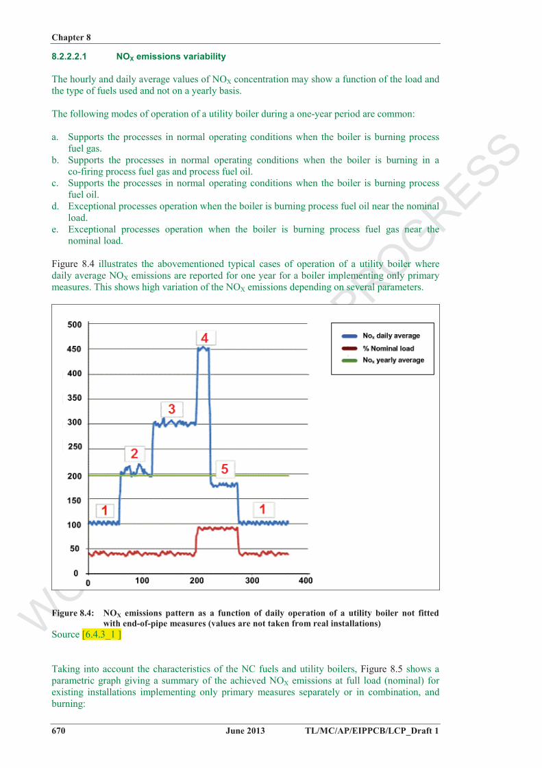
The following modes of operation of a utility boiler during a one-year period are common:
a. Supports the processes in normal operating conditions when the boiler is burning process fuel gas.
b. Supports the processes in normal operating conditions when the boiler is burning in a co-firing process fuel gas and process fuel oil.
c. Supports the processes in normal operating conditions when the boiler is burning process fuel oil.
d. Exceptional processes operation when the boiler is burning process fuel oil near the nominal load.
e. Exceptional processes operation when the boiler is burning process fuel gas near the nominal load.
Figure 8.4 illustrates the abovementioned typical cases of operation of a utility boiler where daily average NOX emissions are reported for one year for a boiler implementing only primary measures. This shows high variation of the NOX emissions depending on several parameters.
Figure 8.4: NOX emissions pattern as a function of daily operation of a utility boiler not fitted with end-of-pipe measures (values are not taken from real installations)
Source [6.4.3_1 ]
Taking into account the characteristics of the NC fuels and utility boilers, Figure 8.5 shows a parametric graph giving a summary of the achieved NOX emissions at full load (nominal) for existing installations implementing only primary measures separately or in combination, and burning:

WORKIN
G DRAFT IN
PROGRESS
Chapter 8
TL/MC/AP/EIPPCB/LCP_Draft 1 June 2013 671
Process fuel oil (PFO) with high N content (left side of the horizontal axis) Process fuel gas (PFG) with a typical composition (H2 + other species) in a petrochemical
process normal operation (right side of the horizontal axis) Process fuel gas and process fuel oil (PFG + PFO), simultaneously in several ratios.
Figure 8.5 is based on several measurements and parametric observations of NOX emissions achieved at nominal load with the implementation of primary measures in retrofitted existing utility boilers in the chemical industry. Figure 8.5 also illustrates the following effects:
a. The NOX emissions do not follow a linear evolution for different mix of PFG and PFO, but indicate clearly a peak for a ratio of 33 % of process fuel gas (TWG: please clarify if it is in weight, volume, or LCV?). This particular effect (well known and experienced by the LNB manufacturers) is due to the fuel gas igniting faster than the fuel oil and then communicating its adiabatic heat to the fuel oil. The oil ignites at a later stage, causing more NOX at a higher oxidation level. This shows why the combination of the two different flames can increase the NOX emissions and why a linear extrapolation may not be applied.
b. The NOX emissions with fuel oil are very dependent on the level of nitrogen content in the fuel oil: higher nitrogen content leads to a higher “peak effect”. NOX emissions in untreated flue-gas increase by 70-80 mg/Nm³ per 0.1% of nitrogen content.
c. Retrofitting the boiler in order to allow fuel flexibility gives new opportunities to control NOX emissions by operational adjustments. Therefore, a burner revamp that allows for fuel flexibility may also be part of the NOX reduction performances, and the retrofitting works will concern not only the installation of the LNB and associated devices but also the study and works to install new fuel skids.
Figure 8.5: NOX emissions pattern in untreated flue-gas as a function of fuel blend at nominal load – data (accuracy: 20%) collected from retrofitted installations with primary measures
Source [6.4.3_1 ]
8.2.3 Techniques to consider in the determination of BAT for the combustion of NC fuel

WORKIN
G DRAFT IN
PROGRESS
Chapter 8
672 June 2013 TL/MC/AP/EIPPCB/LCP_Draft 1
This section describes techniques (or combinations thereof), and associated monitoring,considered to have the potential for achieving a high level of environmental protection in the activities within the scope of this document. The techniques described will include both the technology used and the way in which the installations are designed, built, maintained, operated, and decommissioned.
It covers process-integrated techniques and end-of-pipe measures. Waste prevention and management, including waste minimisation and recycling procedures are also considered. Furthermore, techniques for reducing the consumption of raw materials, water, and energy are covered.
Annex III to the Industrial Emissions Directive lists a number of criteria for determining BAT, and the information within this chapter will address these considerations. As far as possible, the standard structure of Table 3.8 is used to outline the information on each technique, to enable a comparison of techniques and the assessment against the definition of BAT given in the Industrial Emissions Directive.
This section does not necessarily provide an exhaustive list of techniques that could be applied in the sector. Other techniques may exist or may be developed, which could be considered for the determination of BAT for an individual installation.
In this section, the techniques to be considered have only been fully described when they are specific to the considered combusted fuel or applied combustion process (combustion of biomass and peat). Indeed, for most of the techniques general descriptions are already presented in Chapter 3, therefore, in order to avoid repetitions, only specific-related information is reported here for these general techniques in synthetic tables.
8.2.3.1 Techniques for the prevention and control of NOX, N2O, CO and NH3emissions
Information on general techniques, including information on complete combustion, for the prevention and control of NOX and N2O emissions, CO and NH3 emissions are given in section 3.3. Table 5.45 and Figure 8.6 give information specific to NC fuel-firing, e.g. on applicability, environmental performances and example plants. Figure 8.7 show two examples of typical utility boilers arrangements that could experience difficulty in implementing some techniques due to the configuration of the furnace. Finally Figure 8.8 shows the retrofit of OFA primary technique in a boiler within a chemical installation.

WORKIN
G DRAFT IN
PROGRESS
Cha
pter
8
TL
/MC
/AP/
EIP
PCB
/LC
P_D
raft
1
June
201
3 67
3
Tab
le 8
.2:
Tec
hniq
ues f
or th
e pr
even
tion
and
cont
rol o
f NO
Xan
d N
2Oem
issi
ons
Technique
Technical description
Achieved environmental benefits
Environmental performance and operational data
Cross-media effects
Technical considerations relevant to applicability
New plantsRetrofitable
Economics
Driving force for implementation
Example plants
Reference literature Remarks
Prim
ary
mea
sure
s
Fuel
stag
ed
com
bust
ion
(reb
urni
ng)
Air-
stag
ing
Ove
r Fire
d A
ir (O
FA):
LNB
ar
e op
erat
ed a
t low
air
stoi
chio
met
ry w
hile
com
plet
e co
mbu
stio
n is
ach
ieve
d by
in
ject
ion
of th
e ad
ditio
nal a
ir ab
ove
the
burn
ers i
n th
e up
per s
ectio
n of
the
boile
r
The
OFA
air
ports
can
be
impl
emen
ted
abov
e th
e bu
rner
s if
suffi
cien
t spa
ce to
ach
ieve
the
com
plet
e co
mbu
stio
n is
left
in
the
fireb
ox :
(res
trict
ed si
ze o
f th
e fu
rnac
e fo
r OFA
)
Flue
-gas
reci
rcul
atio
n (F
GR
)
The
adia
batic
flam
e te
mpe
ratu
re o
f the
LN
B c
an
be re
duce
d by
reci
rcul
atin
g a
porti
on o
f the
flue
-gas
with
th
e co
mbu
stio
n ai
r in
the
burn
er w
indb
ox. T
his m
akes
FG
R n
ot e
ffici
ent a
s te
chni
que
for o
il fir
ing.
R
etro
fittin
g re
quire
s new
bu
rner
des
ign
The
tech
niqu
e is
mor
e ef
ficie
nt
whe
n bu
rnin
g fu
el g
as.
Whe
n bu
rnin
g fu
el
oil,
poor
co
mbu
stio
n, a
nd
flam
e in
stab
ility
ca
n re
sult
in
mal
func
tions
and
in
crea
ses i
n du
st em
issi
ons
Red
uced
ther
mal
ef
ficie
ncy
Res
trict
ed si
ze o
f the
furn
ace
and
win
dbox
(to
acce
pt th
e to
tal f
low
of
the
com
bust
ion
air a
nd
flue-
gas r
atio
with
out p
ress
ure
drop
in th
e co
mbu
stio
n ai
r ci
rcui
t) m
ay h
ampe
r ret
rofit
ting

WORKIN
G DRAFT IN
PROGRESS
Cha
pter
8
674
June
201
3 T
L/M
C/A
P/E
IPPC
B/L
CP_
Dra
ft 1
Technique
Technical description
Achieved environmental benefits
Environmental performance and operational data
Cross-media effects
Technical considerations relevant to applicability
New plantsRetrofitable
Economics
Driving force for implementation
Example plants
Reference literature Remarks
Adv
ance
d lo
w-N
OX
burn
ers
Seco
ndar
y m
easu
res
Sele
ctiv
e N
on
Cat
alyt
ic R
educ
tion
(SN
CR
)
The
perfo
rman
ce
of th
e SN
CR
de
pend
s on
the
conf
igur
atio
n an
d ge
omet
ry o
f the
m
ulti
burn
er
furn
ace.
Coa
ting
corr
osio
n pr
oble
ms o
n th
e bo
iler
wat
er w
all t
ubes
Tota
l CA
PEX
3.
5 - 4
mill
ion
EU
RN
Ox
redu
ctio
n:
62 t/
y
Spec
ific
inve
stm
ent
(NO
x av
oide
d)
56 E
UR
/kg
Sele
ctiv
e C
atal
ytic
R
educ
tion
(SC
R)
Safe
ty c
onsi
dera
tions
rais
ed b
y th
e vi
cini
ty o
f oth
er fa
cilit
ies t
hat
coul
d po
tent
ially
gen
erat
e ex
plos
ive
atm
osph
eres
. Sp
ace
avai
labi
lity,
duc
t siz
e an
d co
nfig
urat
ion
to in
terv
ene
in th
e op
timal
te
mpe
ratu
re w
indo
w (f
or S
CR
). R
estri
cted
size
of t
he fu
rnac
e (fo
r SN
CR
)

WORKIN
G DRAFT IN
PROGRESS
Chapter 8
TL/MC/AP/EIPPCB/LCP_Draft 1 June 2013 675
Figure 8.6: NC-fuel-fired boilers - NOX emission concentrations; yearly averages; 5th and 95th
percentiles of short-term values are represented as span bars
Most of the plants represented in Figure 8.6 continuously monitor NOX emission concentrations and average short-term values (hourly, daily, or half-hourly basis); few plants monitor periodically. Some plants include also other-than-normal operating conditions emissions data. For the represented combustion plants, the thermal rated input is in the range 100 – 300 MWth; they are old plants (built before 1980, with the exception of the first two); the plants are operated more than 4000 h/yr, with equivalent load modes ranging from 12 to 85 %. The first three plants are burning only a gaseous fuels mixture with a H2 content up to 70%.
Figure 8.7: Utility boilers arrangements

WORKIN
G DRAFT IN
PROGRESS
Chapter 8
676 June 2013 TL/MC/AP/EIPPCB/LCP_Draft 1
Figure 8.8: Over-fire air
8.2.3.2 Techniques for the prevention and control of other pollutants
Ex Section 7.1.7: The by-products of chemical plants can contain dust and sulphur. These gases are often burnt with other fuels (NG, HFO) in combustion power plants equipped with primary and orsecondary measures (e.g. ESP, FGD technology); secondary measures are implemented to reduce the dust and sulphur emissions when the primary measures are not sufficient. See Figure 9.1 for performances (SOX emissions levels) and example plants.

WORKIN
G DRAFT IN
PROGRESS
Chapter 8
TL/MC/AP/EIPPCB/LCP_Draft 1 June 2013 677
Figure 8.9: NC-fuel-fired boilers - SOX emission concentrations; yearly averages; 5th and 95th
percentiles of short-term values are represented as span bars
Retrofitting existing boilers within a chemical installation may be difficult due to the size and the configuration of the flue-gas duct or the lack of sufficient space near the utility boiler. These general constraints for existing combustion plants become more stringent for boilers built within chemical installations.
Information on general techniques for the prevention and control of dust and particle-bound metals emissions and SOX are given in Section 3.3. Additional information is given in Chapter 6 and 7, respectively, on combustion plants using liquid and gaseous fuels.
Some fuel pretreatment techniques are described in the BAT reference document on Common Waste Water and Waste Gas Treatment/Management Systems in the Chemical Sector (CWW BREF) and in the other chemical industry BREFs.
TWG: please provide additional information on secondary measures to control pollutants other than NOX in the combustion of NC fuels.