8 Burners Event Grill -...
24
8 Burners Event Grill Model: ST1017-012939 OPERATOR’S MANUAL For Outdoor Use Only Thank you for purchasing this outdoor cooking appliance. Please read Safety and Precaution statements, Grill Maintenance, Leak Testing Regulator / Cylinder connection and Lighting Grill before using grill for first time, z This instruction manual contains important information necessary for the proper assembly and safe use of the appliance. z Read and follow all warnings and instructions before assembling and using the appliance. z Follow all warnings and instructions when using the appliance. z Keep these manual for further reference. As RanKam we ‘re the experts on this product and trained to help you with: Assembly Questions Grill operation Replacements of damaged or missing parts, please contact Toll Free 1-888-837-1380
Transcript of 8 Burners Event Grill -...
8 Burners Event GrillModel: ST1017-012939
OPERATOR’S MANUAL
For Outdoor Use OnlyThank you for purchasing this outdoor cooking appliance.Please read Safety and Precaution statements, Grill Maintenance, Leak Testing Regulator /Cylinder connection and Lighting Grill before using grill for first time,
This instruction manual contains important information necessary for the proper assemblyand safe use of the appliance.Read and follow all warnings and instructions before assembling and using the appliance.Follow all warnings and instructions when using the appliance.Keep these manual for further reference.
As RanKam we ‘re the experts on this product and trained to help you with:Assembly QuestionsGrill operationReplacements of damaged or missing parts, please contact
Toll Free 1-888-837-1380
P 2
DANGERIf you smell gas:1. Shut off gas to the appliance.2. Extinguish any open flame.3. If odor continues, keep away from the appliance and immediately call your
gas supplier or your fire department.
WARNINGFOR YOUR SAFETYDo not store or use gasoline or other flammable vapors orliquids in the vicinity of this or any other appliance.
WARNINGImproper installation, adjustment, alteration, service ormaintenance can cause property damage, injury or death.Read the installation, operating and maintenanceinstructions thoroughly before installing or servicing thisequipment.
WARNINGFor Outdoor Use Only.If Stored Indoors, Detach and Leave Cylinder(s) Outdoors.LP-gas supply cylinder must be disconnected when the appliance is not in use.Do not locate this appliance under overhead unprotected combustible surfaces.
This appliance shall be used only outdoors, in well-ventilated. Never use this grill in agarage, porch, shed, breezeway or any other enclosed area.Never put cylinder(s) under grill body in any time.Never obstruct the flow of ventilation air around this grill housing.Never disconnect the gas regulator or any gas fitting while this grill is lit. A lit grill canignite leaking gas and cause a fire or explosion which could result in property damage,personal injury or death.
!!
!!
!!
!!

P 3
Grill Installation Codes
The installation and pressure regulator must conform with local codes, or in the absence of localcodes, with the National Fuel Gas Code, ANSI Z223.1/NFPA 54, or the Natural Gas and PropaneInstallation Code, CSA B149.1, as applicable, including:1. The appliance and its individual shutoff valve must be disconnected from the gas supply
piping system during any pressure testing of that system at test pressures in excess of 1/2psi (3.5 kPa).
2. The appliance must be isolated from the gas supply piping system by closing its individualmanual shutoff valve during any pressure testing of the gas supply piping system at testpressures equal to or less than 1/2 psi (3.5 kPa).
Casters Installation CodeThe installation shall be made with a connector that complies with the Standard for Connectorsfor Movable Gas Appliances, ANSI Z21.69-CSA6.16, and a quick disconnect device thatcomplies with Standard fro Quick –Disconnect Devices for Use With Gas Fuel,ANSIZ21.41.CSA6.9.
To expedite the assembly processes follow these general guidelines:Tools required for Assembly:1. Protective work gloved2. Protective eyewear3. Phillips Head Screwdriver
You will need assistance from another person to handle the grill head and other large, heavyparts.Open Lid of shipping carton and remove top sheet of cardboard and / or packing materials. Laycardboard sheet on floor and use as a work surface to protect floor and grill parts fromscratches.You may slice the carton front corners with a utility knife to lay open the carton front panel. Thisallows you to raise the grill head Lid and remove the components packed inside, making iteasier to lift.Use of Hardware and Part Diagrams to ensure all items are included and free of damage.NOTE: This gas grill is designed to be used with two 20lb LP Gas tanks (not included) for 8burner operation. A tank placed on the right will operate the four right-side burners. A tankplaced on the left will operate the four left-side burners.
Hardware list
No Description Qty Diagram#1 Phillips Head Screws
1/4” x 15mm16
#2 Phillips Head Screws1/4” x 12mm
16
#3 Thumbscrew1/4” x 13mm
4
#4 Phillips Head Screws3/16” x 8mm
4
#5 WasherØ18 x Ø7 x 1mm
4

P 4
Product Diagram

P 5
Parts List
Part Number Part Description Qty1 DQ08A-01-00 Wind shield back panel 12 DQ08A-03-46 Cooking Grid 33 DQ08A-01-02 Wind Shield, right panel 14 DQ08A-03-44 Flame Tamer 85 DQ08A-03-04 Grill Body, back panel 16 DQ08A-03-41 Lead Fire Slot Assy 77 DQ08A-03-02 Grill Body, right panel 18 DQ08A-03-47 Body Post Assy 29 DQ08A-02-01 Side handle 210 DQ08A-02-11 Right side shelf 111 DQ08A-02-09 Towel rack 212 DQ08A-03-26 Regulator 213 DQ08A-03-24 Igniter rod 214 DQ08A-03-34 Baffle Board Assy 215 DQ08A-03-37 Burner Assy 816 DQ08A-03-03 Grill body front panel 117 DQ08A-03-09 Right Valve Install Plank Assy 118 DQ08A-03-17 Right Valve Windpipe Assy 119 DQ08A-03-30 Igniter Cover 220 DQ08A-03-29 Igniter 221 DQ08A-03-15 Control Panel 122 DQ08A-04-10 Grease receptacle 123 DQ08A-04-14 Grease tray 224 DQ08A-04-17/18 Gas Tank Hook 225 DQ08A-04-09 Right Frame Leg Assy 126 DQ08A-05-07 Gas Tank holder 227 DQ08A-05-01 Cart Bottom Frame Assy 128 DQ08A-05-08 Grease Receptacle Bottom Holder 229 DQ08A-05-10 Universal Caster 230 DQ08A-05-09 Directional Caster 231 DQ08A-04-02 Left Frame Leg Assy 132 DQ08A-04-19 Left Cart frame bracket 233 DQ08A-04-20 Right Cart frame bracket 234 DQ08A-04-27 Knob 835 DQ08A-03-28 Knob Holder 836 DQ08A-03-16 Left Valve Windpipe Assy 137 DQ08A-03-06 Left Valve Install Plank Assy 138 DQ08A-02-05 Left Side shelf 139 DQ08A-03-31 Igniter Wire 1 440 DQ08A-03-32 Igniter Wire 2 441 DQ08A-03-01 Left Side Plate, Body 142 DQ08A-03-11 Support, Valve Install Plank 143 DQ08A-01-01 Windshield Left Panel 144 DQ08A-03-33 Gas collector box with Electrode 845 DQ08A-03-05 Strengthen Plank, Body 1
P 6
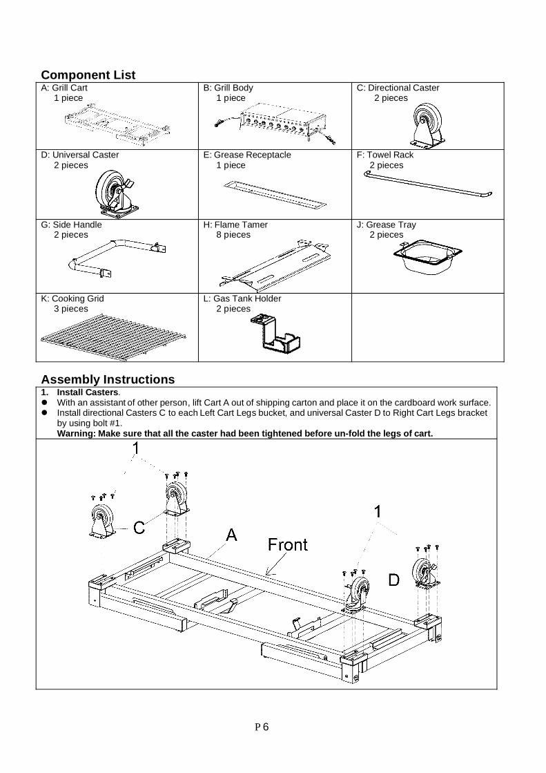
Component ListA: Grill Cart 1 piece
B: Grill Body 1 piece
C: Directional Caster 2 pieces
D: Universal Caster 2 pieces
E: Grease Receptacle 1 piece
F: Towel Rack 2 pieces
G: Side Handle 2 pieces
H: Flame Tamer 8 pieces
J: Grease Tray 2 pieces
K: Cooking Grid 3 pieces
L: Gas Tank Holder 2 pieces
Assembly Instructions1. Install Casters.
With an assistant of other person, lift Cart A out of shipping carton and place it on the cardboard work surface.Install directional Casters C to each Left Cart Legs bucket, and universal Caster D to Right Cart Legs bracketby using bolt #1.Warning: Make sure that all the caster had been tightened before un-fold the legs of cart.
P 7
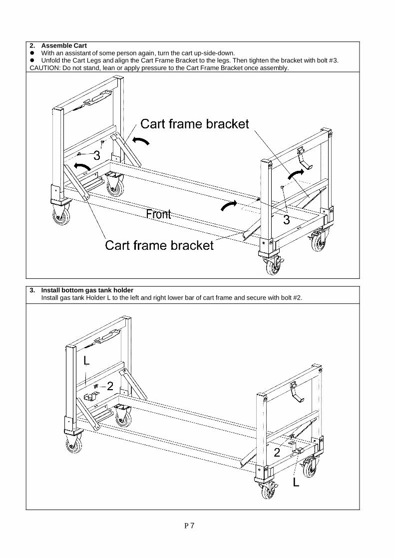
2. Assemble CartWith an assistant of some person again, turn the cart up-side-down.Unfold the Cart Legs and align the Cart Frame Bracket to the legs. Then tighten the bracket with bolt #3.
CAUTION: Do not stand, lean or apply pressure to the Cart Frame Bracket once assembly.
3. Install bottom gas tank holderInstall gas tank Holder L to the left and right lower bar of cart frame and secure with bolt #2.
P 8
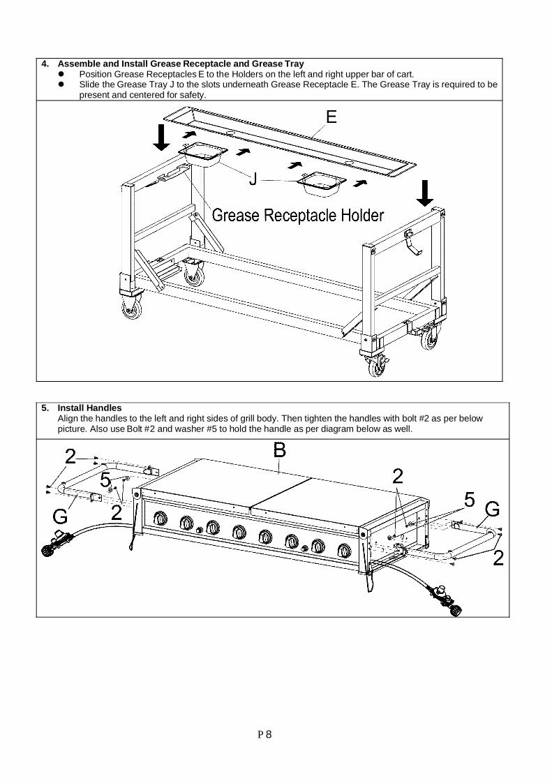
4. Assemble and Install Grease Receptacle and Grease TrayPosition Grease Receptacles E to the Holders on the left and right upper bar of cart.Slide the Grease Tray J to the slots underneath Grease Receptacle E. The Grease Tray is required to bepresent and centered for safety.
5. Install HandlesAlign the handles to the left and right sides of grill body. Then tighten the handles with bolt #2 as per belowpicture. Also use Bolt #2 and washer #5 to hold the handle as per diagram below as well.
P 9
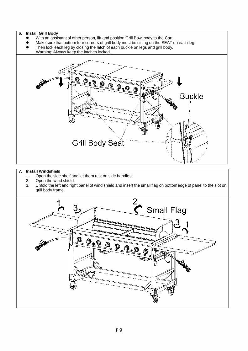
6. Install Grill BodyWith an assistant of other person, lift and position Grill Bowl body to the Cart.Make sure that bottom four corners of grill body must be sitting on the SEAT on each leg.Then lock each leg by closing the latch of each buckle on legs and grill body.
Warning: Always keep the latches locked.
7. Install Windshield1. Open the side shelf and let them rest on side handles.2. Open the wind shield.3. Unfold the left and right panel of wind shield and insert the small flag on bottom edge of panel to the slot on
grill body frame.
P 10
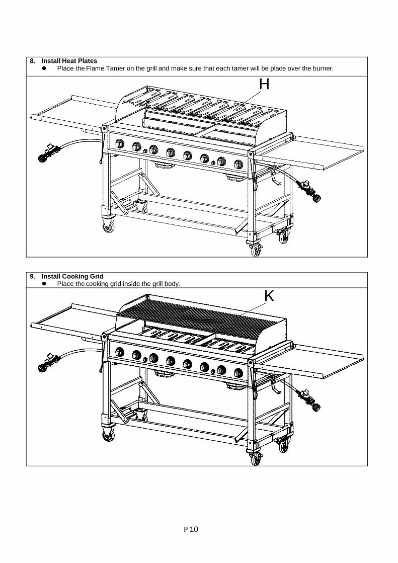
8. Install Heat PlatesPlace the Flame Tamer on the grill and make sure that each tamer will be place over the burner.
9. Install Cooking GridPlace the cooking grid inside the grill body.
P 11
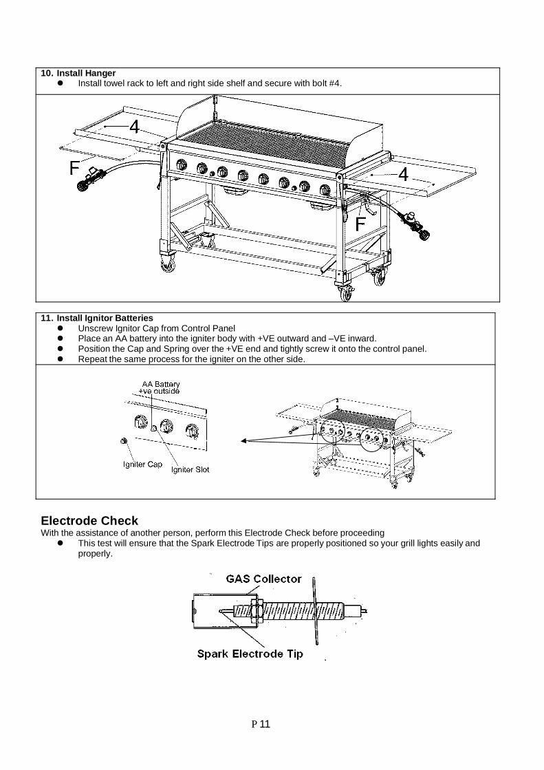
10. Install HangerInstall towel rack to left and right side shelf and secure with bolt #4.
11. Install Ignitor BatteriesUnscrew Ignitor Cap from Control PanelPlace an AA battery into the igniter body with +VE outward and –VE inward.Position the Cap and Spring over the +VE end and tightly screw it onto the control panel.Repeat the same process for the igniter on the other side.
Electrode CheckWith the assistance of another person, perform this Electrode Check before proceeding
This test will ensure that the Spark Electrode Tips are properly positioned so your grill lights easily andproperly.
P 12
Be sure all Control Knobs are set to “OFF” and open the Grill LidsHave your assistant stand behind to the right of the grill and look toward the front of the grill bowl. Never putyour face inside the Grill Head.Press the Igniter Cap, You should hear a “clicking” sound. Your assistant should see a blue spark withineach Gas Collector Box. If a spark is present Electrode Tips are properly positioned..If no spark is seen, the Spark Gap needs to be adjusted as follows:
If no spark is seen, the Spark Gap Electrode Tip and Receiver is more than 3/16” use long nose pliersto gently squeeze the Gas Collector Box to narrow gap.Recheck the Electrode again, if no “clicking” sound is heard:
AA Battery is installed backwards.Electric wires may be loose. Remove the AA Battery and inspect the lgnitor Junction Box foundbehind the Control Panel and reconnect any loose wires.
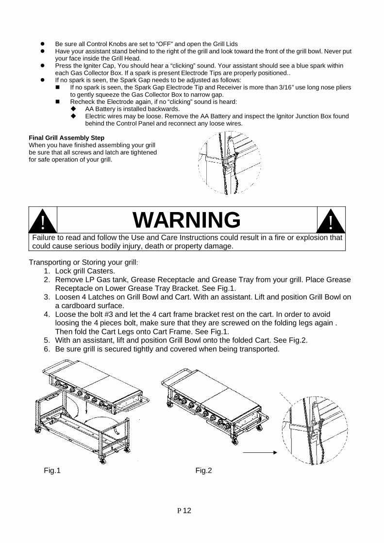
Final Grill Assembly StepWhen you have finished assembling your grillbe sure that all screws and latch are tightenedfor safe operation of your grill.
WARNINGFailure to read and follow the Use and Care Instructions could result in a fire or explosion thatcould cause serious bodily injury, death or property damage.
Transporting or Storing your grill:1. Lock grill Casters.2. Remove LP Gas tank, Grease Receptacle and Grease Tray from your grill. Place Grease
Receptacle on Lower Grease Tray Bracket. See Fig.1.3. Loosen 4 Latches on Grill Bowl and Cart. With an assistant. Lift and position Grill Bowl on
a cardboard surface.4. Loose the bolt #3 and let the 4 cart frame bracket rest on the cart. In order to avoid
loosing the 4 pieces bolt, make sure that they are screwed on the folding legs again .Then fold the Cart Legs onto Cart Frame. See Fig.1.
5. With an assistant, lift and position Grill Bowl onto the folded Cart. See Fig.2.6. Be sure grill is secured tightly and covered when being transported.
Fig.1 Fig.2
!!
P 13
Use and Care InstructionsCorrect LP Gas Tank Use
LP Gas grill models are designed for use with two standard 20 lb. Liquid Propane Gas (LPGas) tanks, not included with grill. Never connect your gas grill to an LP Gas tank thatexceeds this capacity. A tank of approximately 12 inches in diameter by 18-1/2 inches highis the maximum size LP Gas tank to use. You must use an “OPD” gas tank which offersa listed Overfill Prevention Device. This safety feature prevents tank from being overfilledwhich can cause malfunction of LP gas tank, regulator and/ or grill.The LP Gas tank must be constructed and marked in accordance with the Specifications forLP-Gas Cylinders of the U.S. Department of Transportation (D.O.T.) or the NationalStandard of Canada, CAN/ CSA-B339, Cylinders, Spheres and Tubes for Transportation ofDangerous Goods; and Commission, as applicable.The LP Gas tank must have a shutoff valve, terminating in an LP Gas supply tank valveoutlet, that is compatible with a Type 1 tank connection device. The LP Gas tank must alsohave a safety relief device that has a direct connection with the vapor space of the tank.The tank supply system must be arranged for vapor withdrawal.The LP Gas tank used must have a collar to protect the tank valve.When two cylinders are provided, if the gas supply system is set up so that the applianceonly operates on one cylinder at a time, the cylinder not in use, whether filled with fuel orempty, shall be stored and transported on the exterior of the appliance.Never connect an unregulated LP gas tank to your gas grill. The gas regulator assemblysupplied with your gas grill is adjusted to have an outlet pressure of 11” water column (W.C.)for connection to an LP gas tank. Only use the regulator and hose assembly supplied withyour gas grill. Replacement regulators and hose assemblies must be those specified by theManufacture.Have your LP Gas dealer check the release valve after every filling to ensure it remains freeof defects.Always keep LP Gas tank in upright position.Do not subject the LP Gas tank to excessive heat such as a closed car, trunk, or in directsunlight.The LP-gas cylinders are not to be stored in any compartments on the appliance that are notintended for cylinder storage and that such unauthorized storage could lead to an explosion,fire, or personal injury.Never store an LP Gas tank indoors. If you store your gas grill in the garage alwaysdisconnect the LP Gas tank first and store it safety outside.LP Gas tanks must be store outdoors in a well-ventilated area and out of the reach ofchildren.Disconnected LP Gas tanks must not be stored in a building, garage or any other enclosedarea.If the appliance is not in use, the gas must be turned off at the supply cylinder.The cylinder is fitted with a Type I Cylinder Connection Device. A protective dust cap mustbe installed on the valve outlet.The regulator and hose assembly can be seen after opening the doors (if applicable) andmust be inspected before each use of the grill. If there is excessive abrasion or wear or if thehose is cut, it must be replaced prior to using the grill again.Never light your gas grill with the lid closed or before checking to unsure the burner tubesare fully seated over the gas valve orifices.Never allow children to operate your grill. Do not allow children or pets to play near your grill.Use of alcohol, prescription or non-prescription drugs cam impair your ability to properlyassemble and safely operate your grill.Keep your grill covered during freezing rain or snow. Sleet and snow can block the regulatorvent hole resulting in improper and potentially dangerous regulator pressure.Use your grill on a level, stable surface in an area clear of combustible materials.Do not leave grill unattended when is use..Allow the grill to cool before moving or storing. Do not use your grill as a heaterThis grill is not intended to be installed in or on recreational vehicles and/ or boats.

P 14
WARNINGA. Do not store a spare LP-Gas tank under or near this appliance.B. Never fill the tank beyond 80 percent full; andC. If the information in “(a)” and “(b)” is not followed exactly, a fire causing death or serious
injury may occur.
WARNINGUse your grill at least 3 feet away from any wall or surface. Use your grill at least 3 feetaway from combustible objects that can melt or catch fire such as vinyl or wood siding,fences and overhangs or sources of ignition including pilot lights on water heaters and liveelectrical appliance.Outdoor cooking gas appliance shall not be used under overhead combustibleconstruction.The temperatures on the walls adjacent to back sides of the appliance and on the floorunder the appliance, including those wall and floor surface extending beyond the profile ofthe appliance, shall not be more than 117°F (65°C) in excess of room temperature. Theminimum environmental temperature for safe use of the appliance is 32°F (0°C)Keep the appliance area free and clear form combustibles.Never obstruct the flow of ventilation air around your gas grill housing.In windy conditions, always position the front of grill to face oncoming wind to reducesmoke and heat blowing in your face and prevent potential hazards to self and grill.
Use and Care Instructions
Note about LP Gas Tank Exchange ProgramsMany retailers that sell grills offer you the option of replacing your emptyLP Gas tank through an exchange service. Use only those reputableexchange companies that inspect, precision fill, test and certify theirtanks. Exchange your tank only for an OPD safety feature-equippedtank as described in the LP Gas tank section of this manual.Always keep new and exchanged LP Gas tanks in an upright position during use, transit orstorage.Leak test new and exchange LP Gas tanks BEFORE connecting one to your grill.
!!
!!
P 15
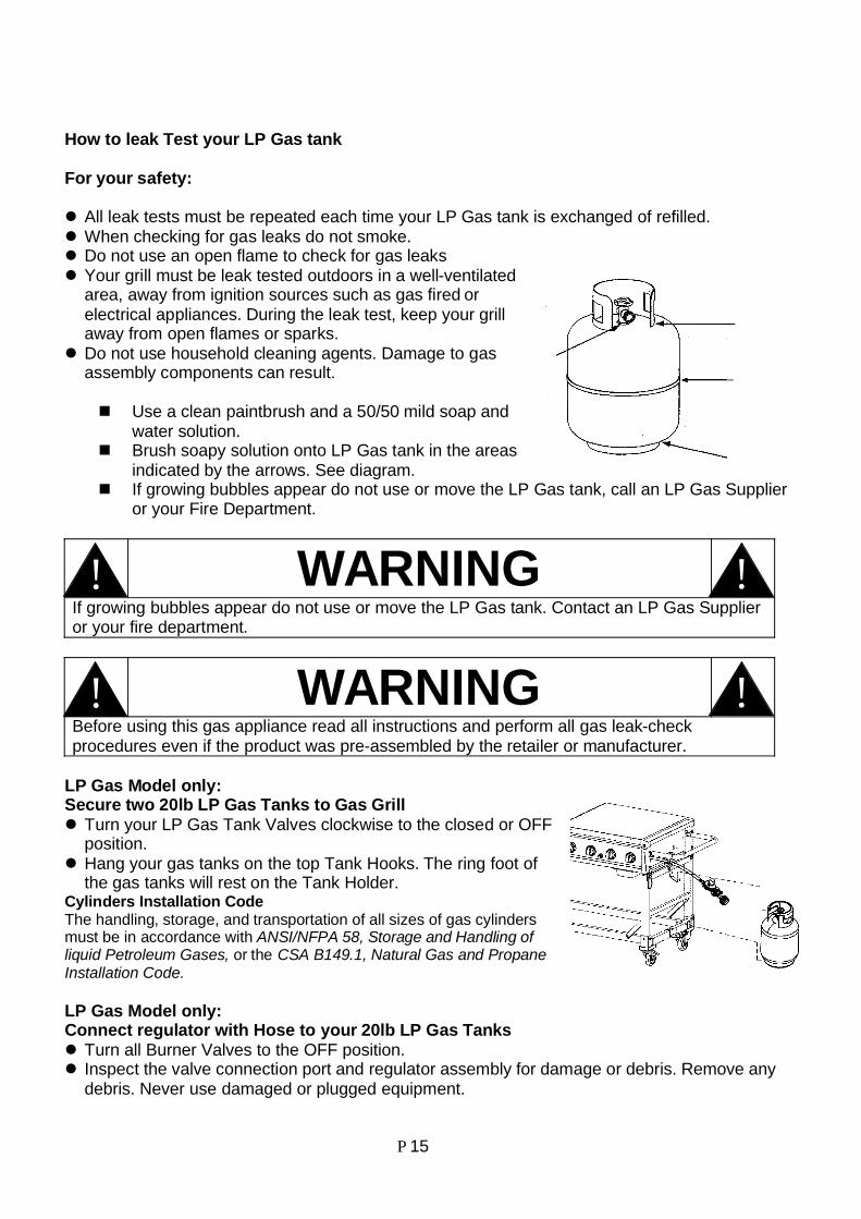
How to leak Test your LP Gas tank
For your safety:
All leak tests must be repeated each time your LP Gas tank is exchanged of refilled.When checking for gas leaks do not smoke.Do not use an open flame to check for gas leaksYour grill must be leak tested outdoors in a well-ventilatedarea, away from ignition sources such as gas fired orelectrical appliances. During the leak test, keep your grillaway from open flames or sparks.Do not use household cleaning agents. Damage to gasassembly components can result.
Use a clean paintbrush and a 50/50 mild soap andwater solution.Brush soapy solution onto LP Gas tank in the areasindicated by the arrows. See diagram.If growing bubbles appear do not use or move the LP Gas tank, call an LP Gas Supplieror your Fire Department.
WARNINGIf growing bubbles appear do not use or move the LP Gas tank. Contact an LP Gas Supplieror your fire department.
WARNINGBefore using this gas appliance read all instructions and perform all gas leak-checkprocedures even if the product was pre-assembled by the retailer or manufacturer.
LP Gas Model only:Secure two 20lb LP Gas Tanks to Gas Grill
Turn your LP Gas Tank Valves clockwise to the closed or OFFposition.Hang your gas tanks on the top Tank Hooks. The ring foot ofthe gas tanks will rest on the Tank Holder.
Cylinders Installation CodeThe handling, storage, and transportation of all sizes of gas cylindersmust be in accordance with ANSI/NFPA 58, Storage and Handling ofliquid Petroleum Gases, or the CSA B149.1, Natural Gas and PropaneInstallation Code.
LP Gas Model only:Connect regulator with Hose to your 20lb LP Gas Tanks
Turn all Burner Valves to the OFF position.Inspect the valve connection port and regulator assembly for damage or debris. Remove anydebris. Never use damaged or plugged equipment.
!!
!!
P 16
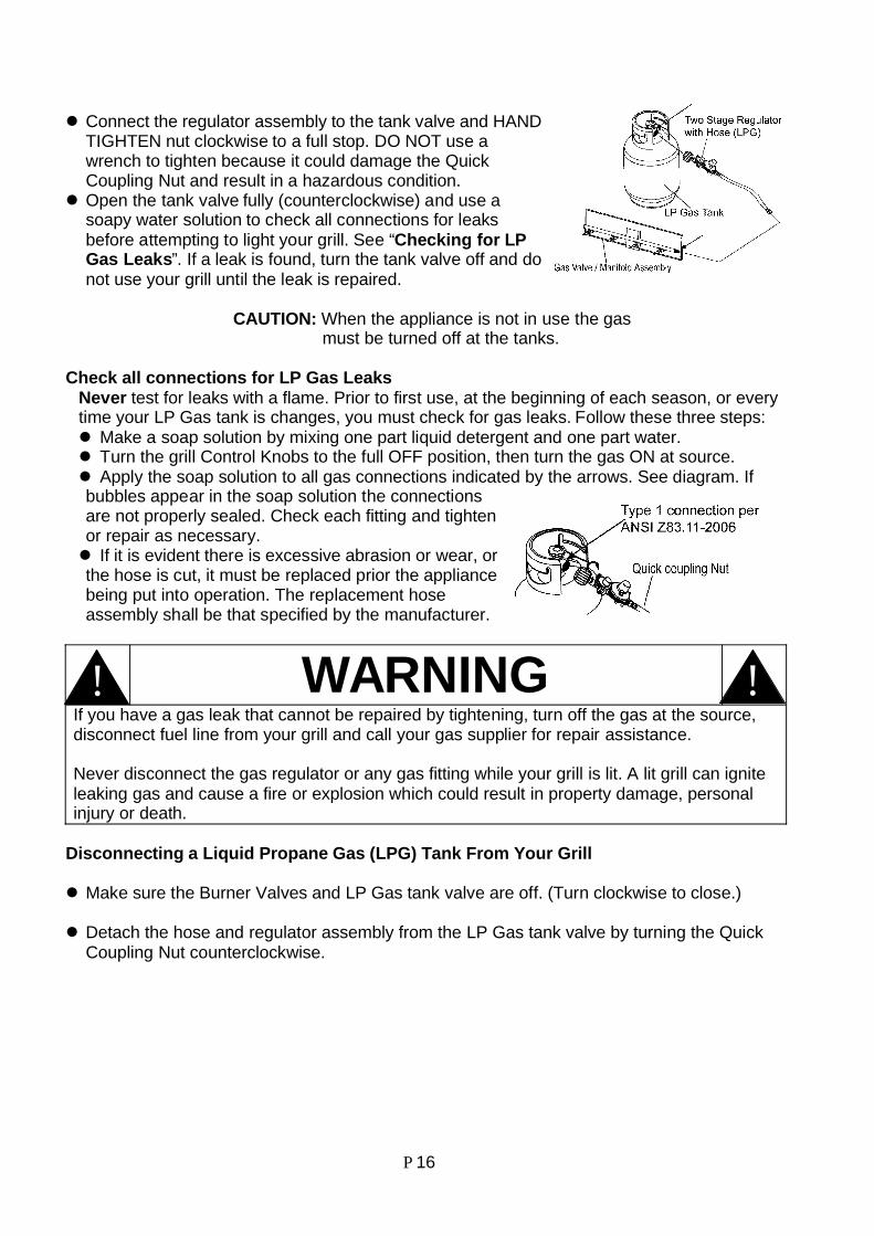
Connect the regulator assembly to the tank valve and HANDTIGHTEN nut clockwise to a full stop. DO NOT use awrench to tighten because it could damage the QuickCoupling Nut and result in a hazardous condition.Open the tank valve fully (counterclockwise) and use asoapy water solution to check all connections for leaksbefore attempting to light your grill. See “Checking for LPGas Leaks”. If a leak is found, turn the tank valve off and donot use your grill until the leak is repaired.
CAUTION: When the appliance is not in use the gasmust be turned off at the tanks.
Check all connections for LP Gas LeaksNever test for leaks with a flame. Prior to first use, at the beginning of each season, or everytime your LP Gas tank is changes, you must check for gas leaks. Follow these three steps:
Make a soap solution by mixing one part liquid detergent and one part water.Turn the grill Control Knobs to the full OFF position, then turn the gas ON at source.Apply the soap solution to all gas connections indicated by the arrows. See diagram. If
bubbles appear in the soap solution the connectionsare not properly sealed. Check each fitting and tightenor repair as necessary.
If it is evident there is excessive abrasion or wear, orthe hose is cut, it must be replaced prior the appliancebeing put into operation. The replacement hoseassembly shall be that specified by the manufacturer.
WARNINGIf you have a gas leak that cannot be repaired by tightening, turn off the gas at the source,disconnect fuel line from your grill and call your gas supplier for repair assistance.
Never disconnect the gas regulator or any gas fitting while your grill is lit. A lit grill can igniteleaking gas and cause a fire or explosion which could result in property damage, personalinjury or death.
Disconnecting a Liquid Propane Gas (LPG) Tank From Your Grill
Make sure the Burner Valves and LP Gas tank valve are off. (Turn clockwise to close.)
Detach the hose and regulator assembly from the LP Gas tank valve by turning the QuickCoupling Nut counterclockwise.
!!
P 17
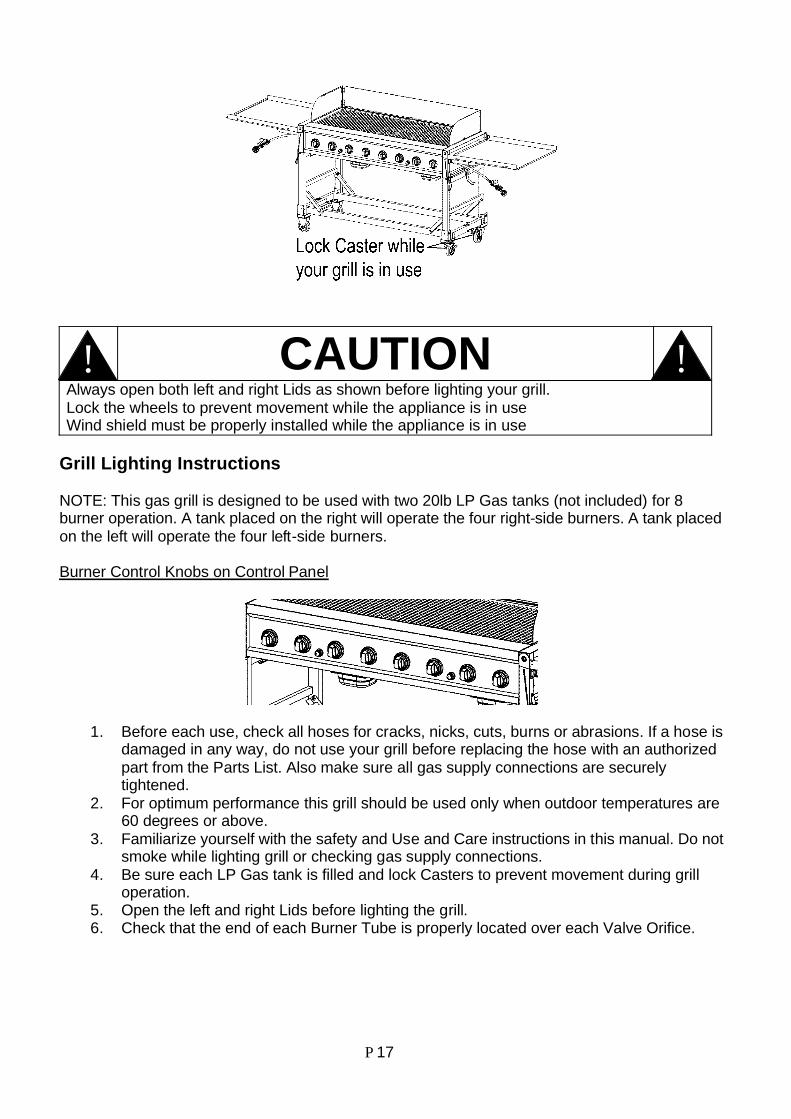
CAUTIONAlways open both left and right Lids as shown before lighting your grill.Lock the wheels to prevent movement while the appliance is in useWind shield must be properly installed while the appliance is in use
Grill Lighting Instructions
NOTE: This gas grill is designed to be used with two 20lb LP Gas tanks (not included) for 8burner operation. A tank placed on the right will operate the four right-side burners. A tank placedon the left will operate the four left-side burners.
Burner Control Knobs on Control Panel
1. Before each use, check all hoses for cracks, nicks, cuts, burns or abrasions. If a hose isdamaged in any way, do not use your grill before replacing the hose with an authorizedpart from the Parts List. Also make sure all gas supply connections are securelytightened.
2. For optimum performance this grill should be used only when outdoor temperatures are60 degrees or above.
3. Familiarize yourself with the safety and Use and Care instructions in this manual. Do notsmoke while lighting grill or checking gas supply connections.
4. Be sure each LP Gas tank is filled and lock Casters to prevent movement during grilloperation.
5. Open the left and right Lids before lighting the grill.6. Check that the end of each Burner Tube is properly located over each Valve Orifice.
!!
P 18
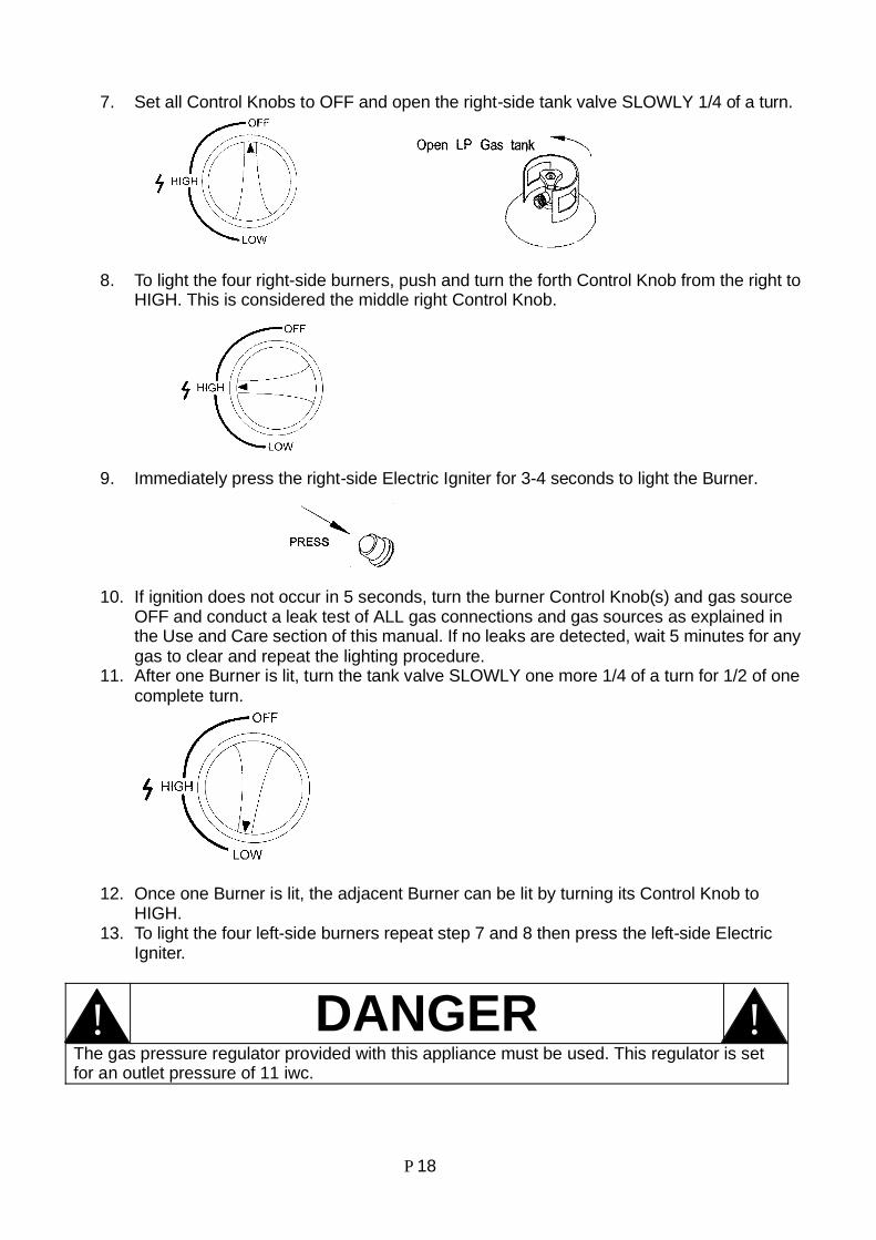
7. Set all Control Knobs to OFF and open the right-side tank valve SLOWLY 1/4 of a turn.
8. To light the four right-side burners, push and turn the forth Control Knob from the right toHIGH. This is considered the middle right Control Knob.
9. Immediately press the right-side Electric Igniter for 3-4 seconds to light the Burner.
10. If ignition does not occur in 5 seconds, turn the burner Control Knob(s) and gas sourceOFF and conduct a leak test of ALL gas connections and gas sources as explained inthe Use and Care section of this manual. If no leaks are detected, wait 5 minutes for anygas to clear and repeat the lighting procedure.
11. After one Burner is lit, turn the tank valve SLOWLY one more 1/4 of a turn for 1/2 of onecomplete turn.
12. Once one Burner is lit, the adjacent Burner can be lit by turning its Control Knob toHIGH.
13. To light the four left-side burners repeat step 7 and 8 then press the left-side ElectricIgniter.
DANGERThe gas pressure regulator provided with this appliance must be used. This regulator is setfor an outlet pressure of 11 iwc.
!!
P 19
WARNINGFailure to replace a faulty hose, secure gas supply connections or to open the Lids beforeproceeding to the Lighting Procedures could result in a fire or explosion could result in a fireor explosion that could cause serious bodily injury, death, or property damage.
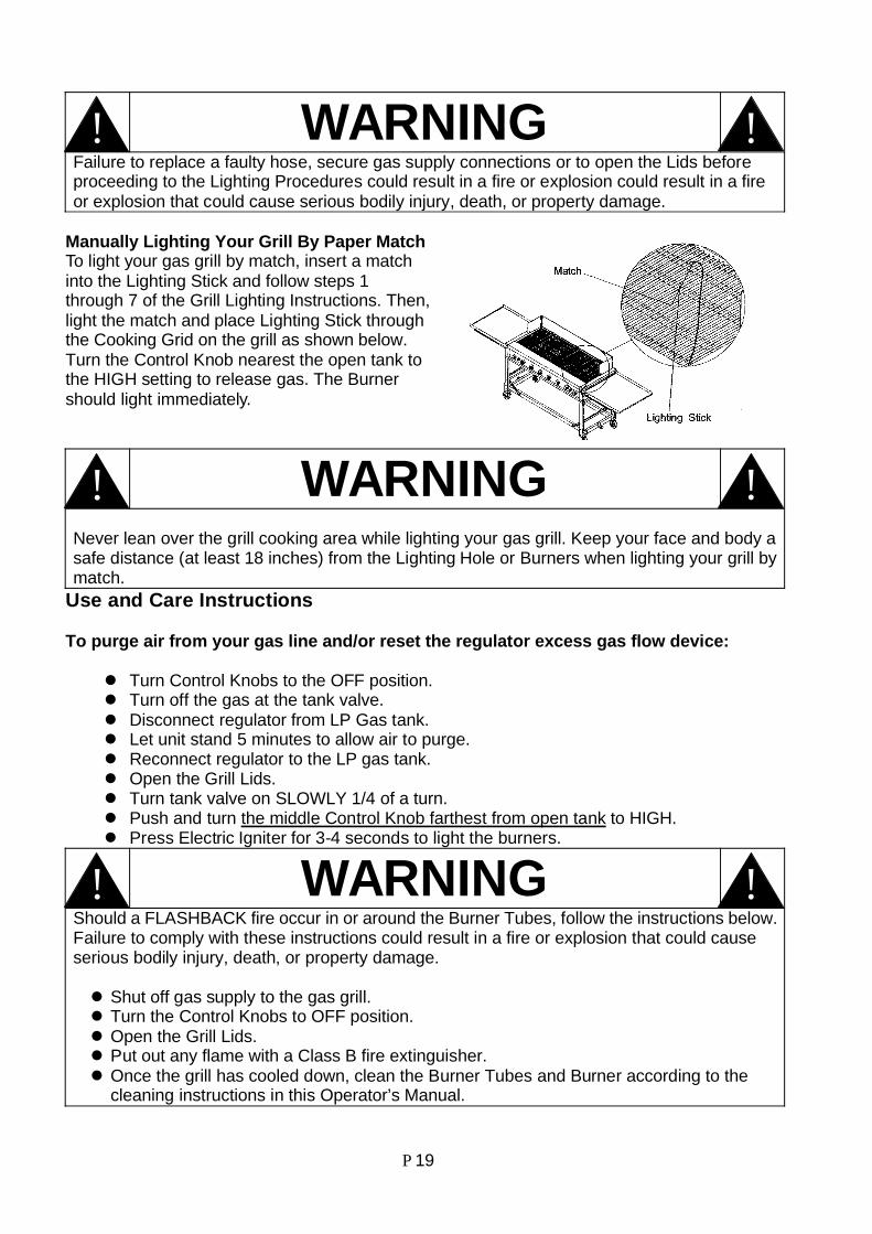
Manually Lighting Your Grill By Paper MatchTo light your gas grill by match, insert a matchinto the Lighting Stick and follow steps 1through 7 of the Grill Lighting Instructions. Then,light the match and place Lighting Stick throughthe Cooking Grid on the grill as shown below.Turn the Control Knob nearest the open tank tothe HIGH setting to release gas. The Burnershould light immediately.
WARNINGNever lean over the grill cooking area while lighting your gas grill. Keep your face and body asafe distance (at least 18 inches) from the Lighting Hole or Burners when lighting your grill bymatch.
Use and Care Instructions
To purge air from your gas line and/or reset the regulator excess gas flow device:
Turn Control Knobs to the OFF position.Turn off the gas at the tank valve.Disconnect regulator from LP Gas tank.Let unit stand 5 minutes to allow air to purge.Reconnect regulator to the LP gas tank.Open the Grill Lids.Turn tank valve on SLOWLY 1/4 of a turn.Push and turn the middle Control Knob farthest from open tank to HIGH.Press Electric Igniter for 3-4 seconds to light the burners.
WARNINGShould a FLASHBACK fire occur in or around the Burner Tubes, follow the instructions below.Failure to comply with these instructions could result in a fire or explosion that could causeserious bodily injury, death, or property damage.
Shut off gas supply to the gas grill.Turn the Control Knobs to OFF position.Open the Grill Lids.Put out any flame with a Class B fire extinguisher.Once the grill has cooled down, clean the Burner Tubes and Burner according to thecleaning instructions in this Operator’s Manual.
!!
!!
!!
P 20
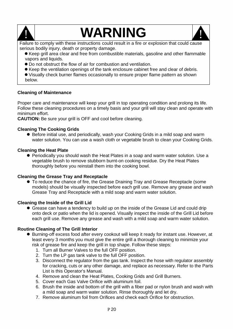
WARNINGFailure to comply with these instructions could result in a fire or explosion that could causeserious bodily injury, death or property damage.
Keep grill area clear and free from combustible materials, gasoline and other flammablevapors and liquids.
Do not obstruct the flow of air for combustion and ventilation.Keep the ventilation openings of the tank enclosure cabinet free and clear of debris.Visually check burner flames occasionally to ensure proper flame pattern as shown
below.
Cleaning of Maintenance
Proper care and maintenance will keep your grill in top operating condition and prolong its life.Follow these cleaning procedures on a timely basis and your grill will stay clean and operate withminimum effort.CAUTION: Be sure your grill is OFF and cool before cleaning.
Cleaning The Cooking GridsBefore initial use, and periodically, wash your Cooking Grids in a mild soap and warmwater solution. You can use a wash cloth or vegetable brush to clean your Cooking Grids.
Cleaning the Heat PlatePeriodically you should wash the Heat Plates in a soap and warm water solution. Use avegetable brush to remove stubborn burnt-on cooking residue. Dry the Heat Platesthoroughly before you reinstall them into the cooking bowl.
Cleaning the Grease Tray and ReceptacleTo reduce the chance of fire, the Grease Draining Tray and Grease Receptacle (somemodels) should be visually inspected before each grill use. Remove any grease and washGrease Tray and Receptacle with a mild soap and warm water solution.
Cleaning the Inside of the Grill LidGrease can have a tendency to build up on the inside of the Grease Lid and could driponto deck or patio when the lid is opened. Visually inspect the inside of the Grill Lid beforeeach grill use. Remove any grease and wash with a mild soap and warm water solution.
Routine Cleaning of The Grill InteriorBurning-off excess food after every cookout will keep it ready for instant use. However, atleast every 3 months you must give the entire grill a thorough cleaning to minimize yourrisk of grease fire and keep the grill in top shape. Follow these steps:
1. Turn all Burner Valves to the full OFF position.2. Turn the LP gas tank valve to the full OFF position.3. Disconnect the regulator from the gas tank. Inspect the hose with regulator assembly
for cracking, cuts or any other damage, and replace as necessary. Refer to the PartsList is this Operator’s Manual.
4. Remove and clean the Heat Plates, Cooking Grids and Grill Burners.5. Cover each Gas Valve Orifice with aluminum foil.6. Brush the inside and bottom of the grill with a fiber pad or nylon brush and wash with
a mild soap and warm water solution. Rinse thoroughly and let dry.7. Remove aluminum foil from Orifices and check each Orifice for obstruction.
!!

P 21
8. Check each Spark Electrode, adjusting as needed. The space between the SparkElectrode Tip and Spark Receiver should be approximately 3/16”.
9. Replace the Burners and adjust the Gas Collector Box. The edge of the collector boxshould be overlapping the Burner Port.
10.Replace Saver Plates TM and Cooking Grids.11.Reconnect the gas source and observe the Burner flame for correct operation.
Cleaning Exterior Painted Surfaces:Before initial use, and periodically thereafter, we suggest you wash your grill using a mildsoap and warm water solution. You can use a wash cloth or sponge for this process. Donot use a stiff wire or brass brush. These will scratch stainless steel and chip paintedsurfaces (varies by model) during the cleaning process.
Cleaning Exterior Stainless Steel Surfaces:Routine care and maintenance is required to preserve the appearance and corrosionresistance of stainless steel. The fact is stainless steel can corrode, rust and discolorunder certain conditions. Rust is caused when regular steel particles in the atmospherebecome attached to the stainless steel surface. Steel particles can also becomeattached to group grill if you use steel wool or stiff wire brushes to clean the grill insteadof non-abrasive cloth, sponge or nylon cleaning tools. In coastal areas rust pits candevelop on stainless surfaces that cannot be fully removed. Bleach and other chlorinebased solutions used for household and pool cleaning can also cause corrosion tostainless steel. Weathering, extreme heat, smoke from cooking and machine oils used inthe manufacturing process of stainless steel can cause stainless steel to turn tan in color.Although there are many factors which can affect the surface appearance of stainlesssteel, they do not affect the integrity of the steel of the performance of the grill.To help maintain the finish of stainless steel follow these cleaning procedures for thebest results:1. After every use (after your grill has cooled down), wipe stainless surfaces with a soft,
soapy cloth or sponge then rinse with water. Be sure to remove all food particles,sauces or marinades from stainless steel because these can be highly acidic anddamaging to stainless surface.
2. Never use abrasive cleaners, scrubbers or stiff wire brushes of any type on your grill.3. Use a heat resistant Stainless Steel Cleaner and rub or wipe in the direction of the
stainless steel grain or polish lines NOT against the grain.
Cleaning The Burner Tubes and Burner Ports
To reduce the chance of FLASHBACK FIRE you must clean the Burner Tubes as follows at leastonce a month in summer and fall or whenever spiders are active in your area, and if your grill hasnot been used for an extended period on time.
1. Turn all Burner Valves to the full OFF position.2. Turn the LP Gas tank valve to the full OFF position.3. Detach the LP Gas regulator assembly from your gas grill.4. Remove the Cooking Grids, Flame Tamer and Grease Trays from your grill.5. Remove the screw from the rear of each Burner using a Phillips Head Screwdriver.6. Carefully lift each Burner up and away from the Gas Valve Orifice.7. Check and clean burner/ venture tubes for insects and insect nests. A clogged tube can lead
to a fire beneath the grill.8. Refer to Figure 1 and perform one of these three cleaning methods:
P 22
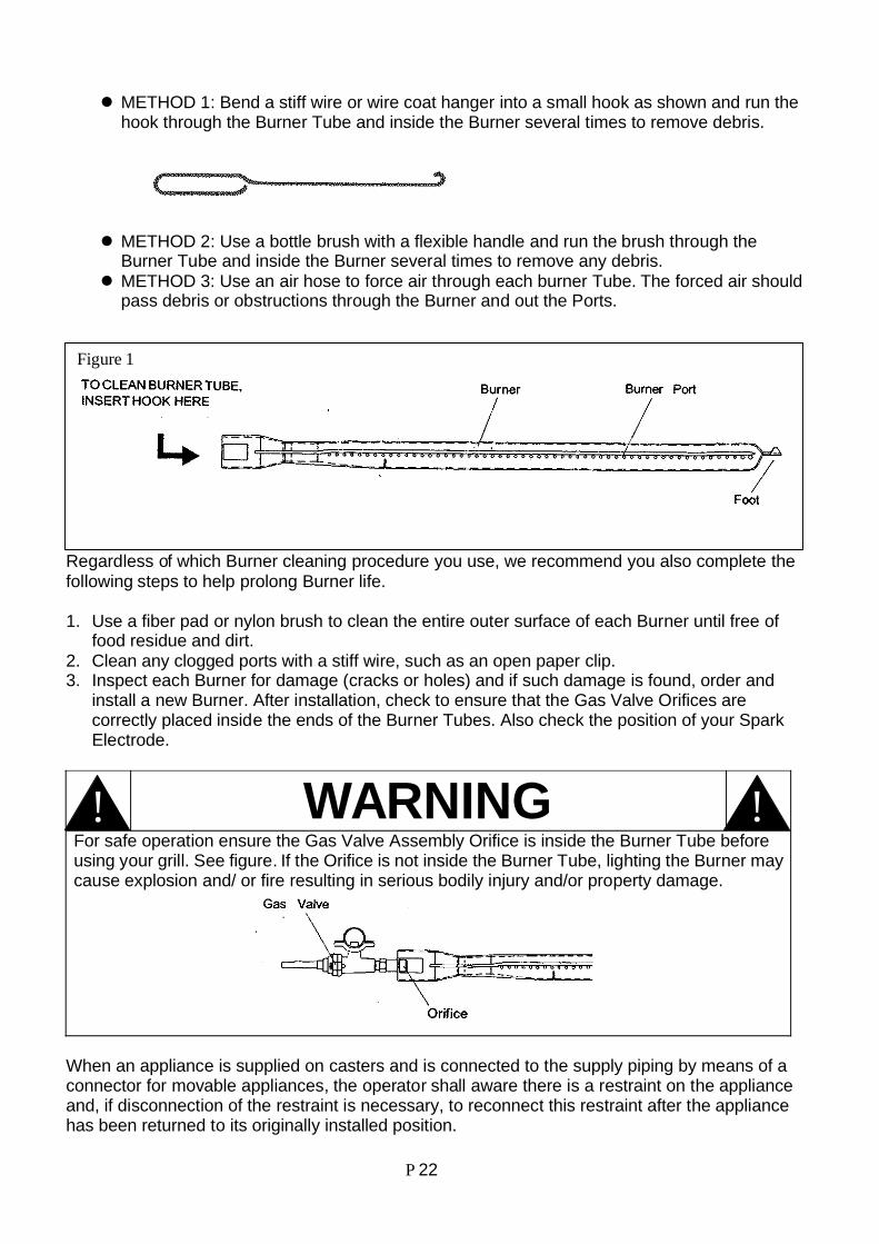
METHOD 1: Bend a stiff wire or wire coat hanger into a small hook as shown and run thehook through the Burner Tube and inside the Burner several times to remove debris.
METHOD 2: Use a bottle brush with a flexible handle and run the brush through theBurner Tube and inside the Burner several times to remove any debris.METHOD 3: Use an air hose to force air through each burner Tube. The forced air shouldpass debris or obstructions through the Burner and out the Ports.
Regardless of which Burner cleaning procedure you use, we recommend you also complete thefollowing steps to help prolong Burner life.
1. Use a fiber pad or nylon brush to clean the entire outer surface of each Burner until free offood residue and dirt.
2. Clean any clogged ports with a stiff wire, such as an open paper clip.3. Inspect each Burner for damage (cracks or holes) and if such damage is found, order and
install a new Burner. After installation, check to ensure that the Gas Valve Orifices arecorrectly placed inside the ends of the Burner Tubes. Also check the position of your SparkElectrode.
WARNINGFor safe operation ensure the Gas Valve Assembly Orifice is inside the Burner Tube beforeusing your grill. See figure. If the Orifice is not inside the Burner Tube, lighting the Burner maycause explosion and/ or fire resulting in serious bodily injury and/or property damage.
When an appliance is supplied on casters and is connected to the supply piping by means of aconnector for movable appliances, the operator shall aware there is a restraint on the applianceand, if disconnection of the restraint is necessary, to reconnect this restraint after the appliancehas been returned to its originally installed position.
Figure 1
!!

P 23
P 24
Limited WarrantyManufacturer warrants this Event Grill for replacement or repair of parts and/or workmanship for aperiod of 3 months. Paint is not warranted and may require touch-up. Items considered to beconsumable such as batteries are not covered under these warranties.These limited warranties are made exclusively to the original consumer presenting proof ofpurchase. Any returned goods must be shipped prepaid. These warranties do not cover normalwear and tear or damages resulting from abuse or misuse. This warranty excludes incidental orconsequential cost due to damages or losses to persons or property of any nature.NOTICE: Some states do not allow the exclusion or limitation of incidental or consequentialdamages or limitations on how long an implied warranty lasts, so the above limitations orexclusions may not apply to you.This warranty gives you specific legal rights and you may also have other rights which may varyfrom state to state.For further information or replacement parts, repair and maintenance, please contactmanufacturer,
Toll Free # [email protected]
Rankam Metal Products Manufactory Ltd.1322 Rankin Drive,
Troy, MI 48083.