
8-bit Microcontroller Application Noteww1.microchip.com/downloads/en/AppNotes/doc1497.pdf · 3...
22
AVR035: Efficient C Coding for AVR Features • Accessing I/O Memory Locations • Accessing Memory Mapped I/O • Accessing Data in Flash • Accessing Data in EEPROM • Creating EEPROM Data Files • Efficient Use of Variables and Data Types • Use of Bit-field and Bit-mask • Use of Macros and Functions • Eighteen Ways to Reduce Code Size • Five Ways to Reduce RAM Requirements • Checklist for Debugging Programs • Updated to Support IAR Version 2 Compilers Introduction The C High-level Language (HLL) has become increasingly popular for programming microcontrollers. The advantages of using C compared to Assembler are numerous: Reduced development time, easier maintainability and portability, and easier to reuse code. The penalty can be larger code size and as a result of that often reduced speed. To reduce these penalties the AVR architecture is tuned to efficiently decode and exe- cute instructions that are typically generated by C compilers. The C Compiler development was done by IAR systems before the AVR architecture and instruction set specifications were completed. The result of the co-operation between the compiler development team and the AVR development team is a micro- controller for which highly efficient, high performance code is generated. This application note describes how to utilize the advantages of the AVR architecture and the development tools to achieve more efficient C code than for any other microcontroller. Architecture Tuned for C Code The 32 working registers is one of the keys to efficient C coding. These registers have the same function as the traditional accumulator, except that there are 32 of them. In one clock cycle, AVR can feed two arbitrary registers from the Register File to the ALU, perform an operation, and write back the result to the Register File. When data are stored in the 32 working registers there are no need to move the data to and from memory between each arithmetic instruction. Some of the registers can be combined to 16-bits pointers that efficiently access data in the data and program memories. For large memory sizes the memory pointers can be combined with a third 8-bit register to form 24-bits pointers that can access 16M bytes of data, with no paging. 8-bit Microcontroller Application Note Rev. 1497D–AVR–01/04
Transcript of 8-bit Microcontroller Application Noteww1.microchip.com/downloads/en/AppNotes/doc1497.pdf · 3...

8-bit Microcontroller
Application Note
Rev. 1497D–AVR–01/04
AVR035: Efficient C Coding for AVR
Features• Accessing I/O Memory Locations• Accessing Memory Mapped I/O• Accessing Data in Flash• Accessing Data in EEPROM• Creating EEPROM Data Files• Efficient Use of Variables and Data Types• Use of Bit-field and Bit-mask• Use of Macros and Functions• Eighteen Ways to Reduce Code Size• Five Ways to Reduce RAM Requirements• Checklist for Debugging Programs• Updated to Support IAR Version 2 Compilers
IntroductionThe C High-level Language (HLL) has become increasingly popular for programmingmicrocontrollers. The advantages of using C compared to Assembler are numerous:Reduced development time, easier maintainability and portability, and easier to reusecode. The penalty can be larger code size and as a result of that often reduced speed.To reduce these penalties the AVR architecture is tuned to efficiently decode and exe-cute instructions that are typically generated by C compilers.
The C Compiler development was done by IAR systems before the AVR architectureand instruction set specifications were completed. The result of the co-operationbetween the compiler development team and the AVR development team is a micro-controller for which highly efficient, high performance code is generated.
This application note describes how to utilize the advantages of the AVR architectureand the development tools to achieve more efficient C code than for any othermicrocontroller.
Architecture Tuned for C CodeThe 32 working registers is one of the keys to efficient C coding. These registers havethe same function as the traditional accumulator, except that there are 32 of them. Inone clock cycle, AVR can feed two arbitrary registers from the Register File to theALU, perform an operation, and write back the result to the Register File.
When data are stored in the 32 working registers there are no need to move the datato and from memory between each arithmetic instruction. Some of the registers canbe combined to 16-bits pointers that efficiently access data in the data and programmemories. For large memory sizes the memory pointers can be combined with a third8-bit register to form 24-bits pointers that can access 16M bytes of data, with nopaging.
1
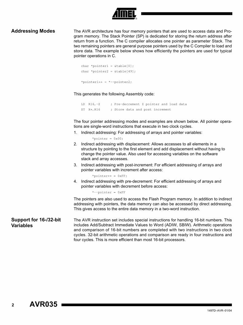
Addressing Modes The AVR architecture has four memory pointers that are used to access data and Pro-gram memory. The Stack Pointer (SP) is dedicated for storing the return address afterreturn from a function. The C compiler allocates one pointer as parameter Stack. Thetwo remaining pointers are general purpose pointers used by the C Compiler to load andstore data. The example below shows how efficiently the pointers are used for typicalpointer operations in C.
char *pointer1 = &table[0];
char *pointer2 = &table[49];
*pointer1++ = *--pointer2;
This generates the following Assembly code:
LD R16,-Z ; Pre-decrement Z pointer and load data
ST X+,R16 ; Store data and post increment
The four pointer addressing modes and examples are shown below. All pointer opera-tions are single-word instructions that execute in two clock cycles.
1. Indirect addressing: For addressing of arrays and pointer variables:*pointer = 0x00;
2. Indirect addressing with displacement: Allows accesses to all elements in a structure by pointing to the first element and add displacement without having to change the pointer value. Also used for accessing variables on the software stack and array accesses.
3. Indirect addressing with post-increment: For efficient addressing of arrays and pointer variables with increment after access:
*pointer++ = 0xFF;
4. Indirect addressing with pre-decrement: For efficient addressing of arrays and pointer variables with decrement before access:
*--pointer = 0xFF
The pointers are also used to access the Flash Program memory. In addition to indirectaddressing with pointers, the data memory can also be accessed by direct addressing.This gives access to the entire data memory in a two-word instruction.
Support for 16-/32-bit Variables
The AVR instruction set includes special instructions for handling 16-bit numbers. Thisincludes Add/Subtract Immediate Values to Word (ADIW, SBIW). Arithmetic operationsand comparison of 16-bit numbers are completed with two instructions in two clockcycles. 32-bit arithmetic operations and comparison are ready in four instructions andfour cycles. This is more efficient than most 16-bit processors.
2 AVR035 1497D–AVR–01/04

AVR035
C Code for AVR
Initializing the Stack Pointer
After Power-up or RESET the Stack Pointer needs to be set up before any function iscalled. The linker command file determines the placement and size of the Stack Pointer.The configuration of memory sizes and Stack Pointer setup is explained in applicationnote “AVR032: Modifying Linker Command Files”.
Accessing I/O Memory Locations
The AVR I/O Memory is easily accessed in C. All registers in the I/O Memory aredeclared in a header file usually named “ioxxxx.h”, where xxxx is the AVR part number.The code below shows examples of accessing I/O location. The assembly code gener-ated for each line is shown below each C code line.
#include <io8515.h> /* Include header file with symbolic names */
__C_task void main(void)
{
char temp; /* Declare a temporary variable*/
/*To read and write to an I/O register*/
temp = PIND; /* Read PIND into a variable*/
// IN R16,LOW(16) ; Read I/O memory
TCCR0 = 0x4F; /* Write a value to an I/O location*/
// LDI R17,79 ; Load value
// OUT LOW(51),R17 ; Write I/O memory
/*Set and clear a single bit */
PORTB |= (1<<PIND2); /* PIND2 is pin number(0..7)in port */
// SBI LOW(24),LOW(2) ; Set bit in I/O
ADCSR &= ~(1<<ADEN); /* Clear ADEN bit in ADCSR register */
// CBI LOW(6),LOW(7) ; Clear bit in I/O
/* Set and clear a bitmask*/
DDRD |= 0x0C; /* Set bit 2 and 3 in DDRD register*/
// IN R17,LOW(17) ; Read I/O memory
// ORI R17,LOW(12) ; Modify
// OUT LOW(17),R17 ; Write I/O memory
ACSR &= ~(0x0C); /* Clear bit 2 and 3 in ACSR register*/
// IN R17,LOW(8) ; Read I/O memory
// ANDI R17,LOW(243) ; Modify
// OUT LOW(8),R17 ; Write I/O memory
/* Test if a single bit is set or cleared */
if(USR & (1<<TXC)) /* Check if UART Tx flag is set*/
{
PORTB |= (1<<PB0);
// SBIC LOW(11),LOW(6) ; Test direct on I/O
// SBI LOW(24),LOW(0)
31497D–AVR–01/04
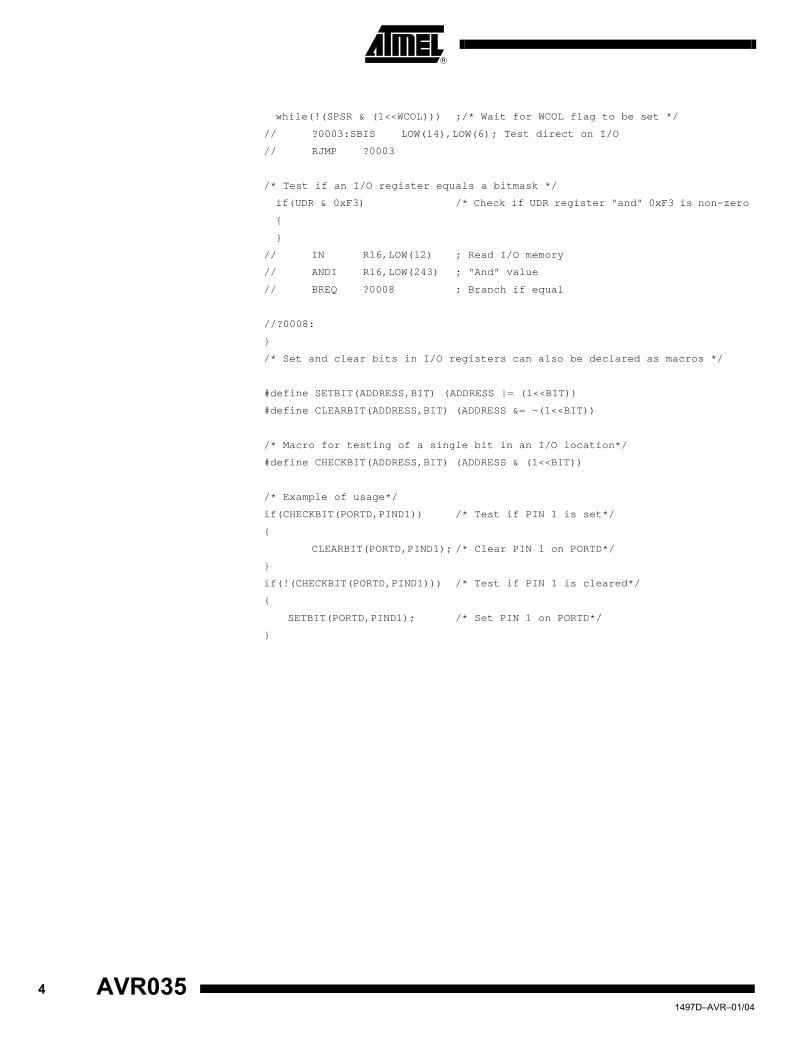
while(!(SPSR & (1<<WCOL))) ;/* Wait for WCOL flag to be set */
// ?0003:SBIS LOW(14),LOW(6); Test direct on I/O
// RJMP ?0003
/* Test if an I/O register equals a bitmask */
if(UDR & 0xF3) /* Check if UDR register "and" 0xF3 is non-zero
{
}
// IN R16,LOW(12) ; Read I/O memory
// ANDI R16,LOW(243) ; "And" value
// BREQ ?0008 ; Branch if equal
//?0008:
}
/* Set and clear bits in I/O registers can also be declared as macros */
#define SETBIT(ADDRESS,BIT) (ADDRESS |= (1<<BIT))
#define CLEARBIT(ADDRESS,BIT) (ADDRESS &= ~(1<<BIT))
/* Macro for testing of a single bit in an I/O location*/
#define CHECKBIT(ADDRESS,BIT) (ADDRESS & (1<<BIT))
/* Example of usage*/
if(CHECKBIT(PORTD,PIND1)) /* Test if PIN 1 is set*/
{
CLEARBIT(PORTD,PIND1); /* Clear PIN 1 on PORTD*/
}
if(!(CHECKBIT(PORTD,PIND1))) /* Test if PIN 1 is cleared*/
{
SETBIT(PORTD,PIND1); /* Set PIN 1 on PORTD*/
}
4 AVR035 1497D–AVR–01/04

AVR035
Accessing Memory Mapped I/O
Some AVR devices include an external Data memory interface. This interface can beused to access external RAM, EEPROM, or it can be used to access memory mappedI/O. The following examples show how to declare, write and read memory mapped I/O:
#include <io8515.h>
#define reg (* (char *) 0x8004)/* Declare a memory mapped I/O address*/
__C_task void main(void)
{
char temp; /* Local temp variable */
reg = 0x05; /* Write a value to the memory mapped address*/
temp = reg; /* Read the memory mapped I/O address */
}
If consecutive memory mapped addresses are accessed, the most efficient way toaccess them is to declare a constant pointer and add an displacement value to this off-set. The example below shows how to access memory mapped I/O this way. Thegenerated assembly code for each instruction is shown in italic.
/* Define the memory mapped addresses */
#define data 0x0003
#define address_high 0x0002
#define address_low 0x0001
__C_task void main(void)
{
/* Start address for memory map */
unsigned char *pointer = (unsigned char *) 0x0800;
// LDI R30,LOW(0) ; Init Z-pointer
// LDI R31,8
*(pointer+address_low) |= 0x40; /* Read and modify one address*/
// LDD R18,Z+1 ; Load variable
// ORI R18,LOW(64) ; Modify
// STD Z+1,R18 ; Store Back
*(pointer+address_high) = 0x00; /* Write an address*/
// STD Z+2,R30 ; Store zero
PORTC = *(pointer+data); /* Read an address*/
// LDD R16,Z+3 ; Load variable
// OUT LOW(21),R16 ; Output to port
}
Note that the Z-pointer is initialized before the memory is accessed, and the LDD andSTD (Load and Store with Displacement) instructions are used to access the data. LDDand STD are one-word instructions that execute in two cycles. The pointer is onlyloaded once. Memory mapped I/O locations can be declared as volatile, this indicatesthat the variable locations may be modified by hardware and the access will not beremoved by optimization.
51497D–AVR–01/04
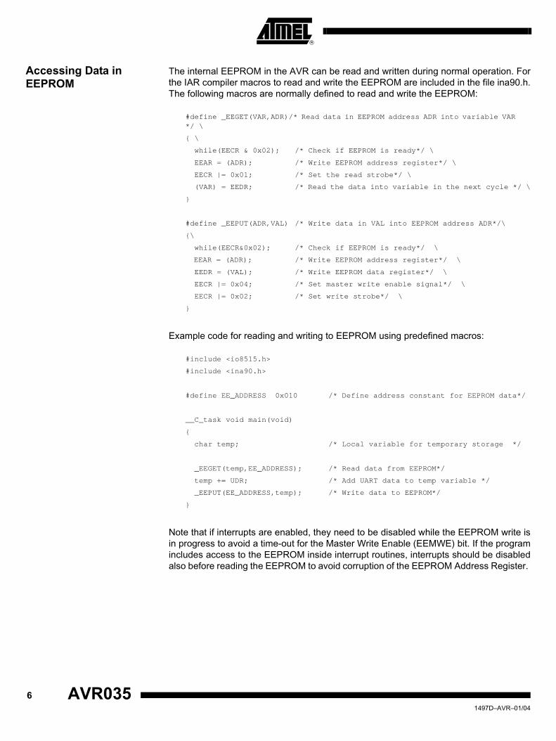
Accessing Data in EEPROM
The internal EEPROM in the AVR can be read and written during normal operation. Forthe IAR compiler macros to read and write the EEPROM are included in the file ina90.h.The following macros are normally defined to read and write the EEPROM:
#define _EEGET(VAR,ADR)/* Read data in EEPROM address ADR into variable VAR */ \
{ \
while(EECR & 0x02); /* Check if EEPROM is ready*/ \
EEAR = (ADR); /* Write EEPROM address register*/ \
EECR |= 0x01; /* Set the read strobe*/ \
(VAR) = EEDR; /* Read the data into variable in the next cycle */ \
}
#define _EEPUT(ADR,VAL) /* Write data in VAL into EEPROM address ADR*/\
{\
while(EECR&0x02); /* Check if EEPROM is ready*/ \
EEAR = (ADR); /* Write EEPROM address register*/ \
EEDR = (VAL); /* Write EEPROM data register*/ \
EECR |= 0x04; /* Set master write enable signal*/ \
EECR |= 0x02; /* Set write strobe*/ \
}
Example code for reading and writing to EEPROM using predefined macros:
#include <io8515.h>
#include <ina90.h>
#define EE_ADDRESS 0x010 /* Define address constant for EEPROM data*/
__C_task void main(void)
{
char temp; /* Local variable for temporary storage */
_EEGET(temp,EE_ADDRESS); /* Read data from EEPROM*/
temp += UDR; /* Add UART data to temp variable */
_EEPUT(EE_ADDRESS,temp); /* Write data to EEPROM*/
}
Note that if interrupts are enabled, they need to be disabled while the EEPROM write isin progress to avoid a time-out for the Master Write Enable (EEMWE) bit. If the programincludes access to the EEPROM inside interrupt routines, interrupts should be disabledalso before reading the EEPROM to avoid corruption of the EEPROM Address Register.
6 AVR035 1497D–AVR–01/04

AVR035
Creating EEPROM Data Files(IAR v2)
Access of variables in EEPROM is greatly improved in version 2 of the IAR compiler.This chapter explains use of EEPROM variables. For use of EEPROM variables in olderversions of the IAR compiler, please see next chapter.
To use the method described below, the “Use inbuilt EEPROM” option must be enabled,and the size must be specified in the compiler options setup. The segment EEPROM_Imust be defined in the linker file
EEPROM variables should be declared as global variables.
Example: To declare a EEPROM variable:
__eeprom volatile unsigned char ee_var = 0xff;
To access this variable in the code, simply read or write the variable like any othervariable:
__C_task void main(void)
{
unsigned char temp;
temp = ee_var;
// LDI R20,LOW(ee_var)
// LDI R21,(ee_var) >> 8
// CALL __eeget8_16
PORTB = temp;
// OUT 0x18,R16
ee_var = TCNT0;
// IN R16,0x32
// LDI R20,LOW(ee_var)
// LDI R21,(ee_var) >> 8
// CALL __eeput8_16
}
When EEPROM variables are declared with initial values, these values can be extractedinto a seperate hex file for programming into the EEPROM using any AVR programmer.
A special program is provided with the IAR compiler to make the seperate file. It is called“postlink.exe” and is located in the “\bin” directory under the IAR installation. Run theprogram without argument for explaination how to use it.
To use the postlink.exe program, the XLINK output format must be set to generate sim-ple format. This is controlled from the XLINK options setup.
71497D–AVR–01/04

Creating EEPROM Data Files(IAR v1)
For access of EEPROM using IAR compiler v2, please see previous chapter. Themethod in this chapter describes methods for accessing EEPROM efficiently using IARcompiler v1.
In some cases it may be convenient to place initial data in the EEPROM and accessthem from the C code. The IAR tools can be used for generating initial data for theEEPROM. By using header files for defining the structures, it can be assured that thestructures are addressable from the C program itself.
The EEPROM data and the program code are two separate projects that must be com-piled and linked separately. A header file describing the structure of the EEPROMmemory is used by both projects to ensure that the data in the EEPROM memory canbe referenced by their symbolic names.
Example The feature will be illustrated through an example. In this example, assume the followingsetup of the EEPROM:
1. A character array (100 bytes).
2. An integer (two bytes).
3. Two unsigned characters (two bytes each).
The EEPROM Header File The EEPROM header file is included both by the program defining the contents of theEEPROM data and the C program accessing the EEPROM. The EEPROM header file isdefined as follows:
#define EEPROMADR(x) (unsigned int) (&((TypeEEPROMStruct *)0x0000)->x)
typedef struct
{
char cArray[100]; /* The character array */
int iNumber; /* The integer */
unsigned char uMinorVersion; /* The first unsigned character */
unsigned char uMajorVersion; /* The second unsigned character */
} TypeEEPROMStruct; /* Just a type name */
The #define directive contains a macro to be used in the C program to get theaddresses of the structure variables. It contains a constant pointer (0x0000). In order todisplace the EEPROM data contents, this pointer, needs to be changed (this will alsorequire a change in the EEPROM linker file, see below).
The EEPROM Program File
The EEPROM Program File (eeprom.c) contains the initialization of the structuredefined in the EEPROM Header File.
#include "eeprom.h" /* Include the structure type definition */
#pragma memory=constseg(EEPROM) /* Make it a named segment */
const TypeEEPROMStruct __EEPROMInitializationData =
{"Testing ", /* Initialize cArray */
0x100 , /* Initialize iNumber */
0x10 , /* Initialize uMinorVersion */
0xFF }; /* Initialize uMajorVersion */
8 AVR035 1497D–AVR–01/04

AVR035
The EEPROM Linker File A very simple Linker File (eeprom.xcl) is required for the EEPROM Program File:
-ca90 -! Define CPU (AVR) -!
-Z(CODE)EEPROM=0-1FF -! EEPROM address space(internal EEPROM memory-!
The address range is here set to 0-1FF (e.g. AT90S8515) and must be changed to thematch the range of the microcontroller being used. The name of the segment isEEPROM and that matches the #pragma memory=constseg(EEPROM) line in the“eeprom.c” sourcefile.
In order to displace the contents of the EEPROM, the start address in the EEPROMsegment must be changed (see also the comment in the EEPROM header file section).
Building the EEPROM Intel-Hex Data File
In order to generate an Intel-Hex file with this content, the following commands arerequired:
icca90 eeprom.c (note that -v1 -ms etc. are of no importance)
xlink -f eeprom.xcl -B -Fintel-standard eeprom.r90 -o eeprom.hex
During linking, the following error message is generated:
Error[46]: Undefined external ?CL0T_1_41_L08 referred in eeprom ( eeprom.r90 )
The C program references an external dummy symbol to make sure that a compiledprogram is linked with the correct version of the library. Since we do not have any libraryto link with, we can ignore this error, and the -B option ensures that the “eeprom.hex” fileis generated even if we do have an error. Alternatively, the file can be linked with the fol-lowing options:
xlink -f eeprom.xcl -D?CL0T_1_41_L08=0 -Fintel-standard eeprom.r90 -o eeprom.hex
The defined symbol is dependent on the processor version (-v0, -v1 etc), the memorymodel (-mt, -ms, etc) and the compiler version, so the symbol can vary from installationto installation (just try to link it, check which undefined symbol it reports and use -D=0).The generated “eeprom intel-hex” file looks like this (eeprom.h):
:1000000054657374696E67202000000000000000D2
:1000100000000000000000000000000000000000E0
:1000200000000000000000000000000000000000D0
:1000300000000000000000000000000000000000C0
:1000400000000000000000000000000000000000B0
:1000500000000000000000000000000000000000A0
:0800600000000000000110FF88
:00000001FF
91497D–AVR–01/04

Accessing the EEPROM Data Structure from a C Program
The following program uses the defined EEPROM structure to access the EEPROM(main.c):
#include "eeprom.h" /* We use the structure and macro */
#include <io8515.h> /* Defines the EEPROM locations */
void error(void) /* An error routine to catch errors */
{
for(;;) /* Do nothing */
;
}
void C_task main(void)
{
int i; /* Used for readback of integer */
EEAR = EEPROMADR(cArray); /* Set up address to 1st element */
EECR |=1; /* Start EEPROM Read */
if(EEDR != 'T') /* Check towards initialization */
error(); /* If not as expected -> error */
EEAR = EEPROMADR(iNumber); /* Set up address to 2nd element */
EECR |=1; /* Start EEPROM Read */
i = EEDR ; /* Set low byte of integer */
EEAR = EEPROMADR(iNumber)+1; /* Set up address to second byte */
EECR |=1; /* Start EEPROM Read */
i |= EEDR<<8; /* Set high byte of integer */
if(i!=0x100) /* Check towards initialization */
error(); /* If not as expected -> error */
EEAR = EEPROMADR(uMinorVersion); /* Set up address to 4th element */
EECR |=1; /* Start EEPROM Read */
if(EEDR != 0x10) /* Check towards initialization */
error(); /* If not as expected -> error */
EEAR = EEPROMADR(uMajorVersion); /* Set up address to 3rd element */
EECR |=1; /* Start EEPROM Read */
if(EEDR != 0xFF) /* Check towards initialization */
error(); /* If not as expected -> error */
for (;;)
; /* Do nothing (success) */
}
The program can be compiled and executed in AVR Studio®. The “eeprom.hex” filemust be loaded into the EEPROM memory before the program is executed or it will goright into the error() routine. The EEPROM is loaded with a hex file by using the File->Up/Download memories function after the program has been loaded.
10 AVR035 1497D–AVR–01/04

AVR035
Variables and Data Types
Data Types As the AVR is an 8-bit microcontroller, use of 16- and 32-bit variables should be limitedto where it is absolutely necessary. The following example shows the code size for aloop counter for an 8-bit and 16-bit local variable:
8-bit Counter unsigned char count8 = 5; /* Declare a varible, assign a value */
// LDI R16,5 ;Init variable
do /* Start a loop */
{
}while(--count8); /* Decrement loop counter and check for zero */
// ?0004:DEC R16 ; Decrement
// BRNE ?0004 ; Branch if not equal
16-bit Counter unsigned int count16 = 6; /* Declare a variable, assign a value */
// LDI R24,LOW(6) ;Init variable, low byte
// LDI R25,0 ;Init variable, high byte
do /* Start a loop */
{
}while(--count16); /* Decrement loop counter and check for zero */
// ?0004:SBIW R24,LWRD(1) ; Subtract 16-bit value
// BRNE ?0004 ; Branch if not equal
Note: 1. Always use the smallest applicable variable type. This is especially important for glo-bal variables.
Efficient Use of Variables A C program is divided into many functions that execute small or big tasks. The func-tions receive data through parameters and may also return data. Variables declaredinside a function are called local variables. Variables declared outside a function arecalled global variables. Variables that are local, but must be preserved between eachtime the function is called, must be declared as static local variables.
Global variables that are declared outside a function are assigned to an SRAM memorylocation. The SRAM location is reserved for the global variable and can not be used forother purposes, this is considered to be waste of valuable SRAM space. Too many glo-bal variables make the code less readable and hard to modify.
Local variables are preferably assigned to a register when they are declared. The localvariable is kept in the same register until the end of the function, or until it is not refer-enced further. Global variables must be loaded from the SRAM into the workingregisters before they are accessed.
The following example illustrates the difference in code size and execution speed forlocal variables compared to global variables.
Table 1. Variable and Code Size(1)
Variable Code Size (Bytes)
8-bit 6
16-bit 8
111497D–AVR–01/04

char global; /* This is a global variable */
__C_task void main(void)
{
char local; /* This is a local variable*/
global -= 45; /* Subtraction with global variable*/
// LDS R16,LWRD(global) ; Load variable from SRAM to register R16
// SUBI R16,LOW(45) ; Perform subtraction
// STS LWRD(global),R16 ; Store data back in SRAM
local -= 34; /* Subtraction with local variable*/
// SUBI R16,LOW(34) ; Perform subtraction directly on local: variable in register R16
}
Note that the LDS and STS (Load and Store Direct from/to SRAM) are used to accessthe variables in SRAM. These are two-word instructions that execute in two cycles.
A local static variable is loaded into a working register at the start of the function andstored back to its SRAM location at the end of the function. Static variables will thereforegive more efficient code than global variables if the variable is accessed more than onceinside the function.
To limit the use of global variables, functions can be called with parameters and return avalue which are commonly used in C. Up to two parameters of simple data types (char,int, long, float, double) are passed between functions in the registers R16 - R23. Morethan two parameters and complex data types (arrays, structs) are either placed on thesoftware stack or passed between functions as pointers to SRAM locations.
Table 2. Code Size and Execution Time for Variables
Variable Code Size (Bytes) Execution Time (Cycles)
Global 10 5
Local 2 1
12 AVR035 1497D–AVR–01/04

AVR035
When global variables are required they should be collected in structures wheneverappropriate. This makes it possible for the C compiler to address them indirectly. Thefollowing example shows the code generation for global variable versus globalstructures.
typedef struct
{
char sec;
}t;
t global /* Declare a global structure*/
char min;
__C_task void main(void)
{
t *time = &global;
// LDI R30,LOW(global) ; Init Z pointer
// LDI R31,(global >> 8) ; Init Z high byte
if (++time->sec == 60)
{
// LDD R16,Z+2 ; Load with displacement
// INC R16; Increment
// STD Z+2,R16 ; Store with displacement
// CPI R16,LOW(60) ; Compare
// BRNE ?0005 ; Branch if not equal
}
if ( ++min == 60)
{
// LDS R16,LWRD(min) ; Load direct from SRAM
// INC R16 ; Increment
// STS LWRD(min),R16 ; Store direct to SRAM
// CPI R16,LOW(60) ; Compare
// BRNE ?0005 ; Branch if not equal
}
}
When accessing the global variables as structures the compiler is using the Z-pointerand the LDD and STD (Load/store with displacement) instructions to access the data.When the global variables are accessed without structures the compiler use LDS andSTS (Load/store direct to SRAM). The difference in code size and will be:
This does not include initialization of the Z-pointer (four bytes) for the global structure.To access one byte the code size will be the same, but if the structure consists of twobytes or more it will be more efficient to access the global variables in a structure.
Table 3. Code Size for Global Variables
Variable Code Size (Bytes)
Structure 10
Non-structure 14
131497D–AVR–01/04

Optimizing Global Flags
Most applications requires some global flags to control the program flow. Placing thesein global variables in inefficient in AVR because the variable must be loaded into theregister before the flag is tested. To optimize the flag testing the flag can either beplaced in a dedicated register, or it can be placed in an unused I/O location.Note: To place a global variable in a dedicated register requires that the register is allocated in
the compiler options setup. This can only be done with IAR Compiler v2.
Unused locations in the I/O Memory can be utilized for storing global variables whencertain peripherals are not used. As example, If the UART is not used the UART BaudRate Register (UBRR) is available, and if the EEPROM is not used both the EEPROMData Register (EEDR) and the EEPROM Address Register (EEAR) will be available tostore global variables.
The I/O Memory is accessed very efficiently, and locations below 0x1F in the I/O Mem-ory are especially suited since they are bit-accessible. I/O locations above 0x1F is lessefficient, but still better than global SRAM variables.
The following examples shows the differenc in code size for using SRAM variables, I/Oarea or a dedicated register for Global Flags:
typedef struct bitfield{// Bitfield structure
unsigned char bit0:1;
unsigned char bit1:1;
unsigned char bit2:1;
}bitfield;
Global Flags in RAM: bitfield global_flag; // Bitfield in a global variable
...
global_flag.bit1 = 1;
// LDI R30,LOW(global_flag)
// LDI R31,(global_flag) >> 8
// LD R16,Z
// ORI R16,0x02
// ST Z,R16
Code Size: 10 bytes
Global Flags in Register R15 Note that bitfields are not allowed as register variables.__no_init __regvar unsigned char reg_flag@ 15;
//Global register R15
...
reg_flag |= 0x01;
// SET
// BLD R15,0
Code size: 4 bytes
14 AVR035 1497D–AVR–01/04

AVR035
Global Flags in Free I/O Registers Above 0x1F
__no_init volatile bitfield high_io_flag@0x55;
// Bitfield in I/O above 0x1F, note that 0x30 offset is added to address
...
high_io_flag.bit2 = 1;
// IN R16,0x35
// ORI R16,0x04
// OUT 0x35,R16
Code size: 6 bytes
Global Flags in Free I/O Register Below 0x1F
__no_init volatile bitfield low_io_flag@0x35;
// Bitfield in I/O location below 0x1F
...
low_io_flag.bit1 = 1;
// SBI 0x15,0x01
Code size: 2 bytes
GPIO registers The advantages of free I/O registers are increased in all new AVR devices. FromATmega169, ATmega48/88/168 and ATtiny2313, all AVR devices includes a number ofGeneral Purpose I/O registers, both below and above the 0x1F address limit. These reg-isters are used as any other free I/O register, and could potentially increaseperformance and reduce code size for your design.
The examples shows using free I/O locations are very efficient for flag variables thatoperates on single bits, while using dedicated registers are efficient for frequentlyaccessed variables. Note that locking registers for global variables limits the compilersability to optimize the code. For complex programs it may increase the code size whendedicating registers for global variables.
Table 4. Code Size (Bytes) for some Common Operations
ActionData in SRAM
Data in I/O Above 0x1F
Data in Register File
Data in I/O Below 0x1F
Set/clear single bit 10 6 4 2
Test single bit 6 4 2 2
Set/clear multiple bits 10 6 4 6
Compare with immediate value 6 4 4 4
151497D–AVR–01/04
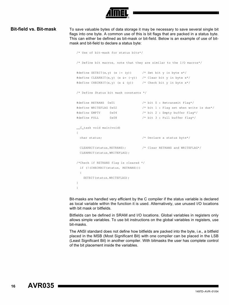
Bit-field vs. Bit-mask To save valuable bytes of data storage it may be necessary to save several single bitflags into one byte. A common use of this is bit flags that are packed in a status byte.This can either be defined as bit-mask or bit-field. Below is an example of use of bit-mask and bit-field to declare a status byte:
/* Use of bit-mask for status bits*/
/* Define bit macros, note that they are similar to the I/O macros*/
#define SETBIT(x,y) (x |= (y)) /* Set bit y in byte x*/
#define CLEARBIT(x,y) (x &= (~y)) /* Clear bit y in byte x*/
#define CHECKBIT(x,y) (x & (y)) /* Check bit y in byte x*/
/* Define Status bit mask constants */
#define RETRANS 0x01 /* bit 0 : Retransmit Flag*/
#define WRITEFLAG 0x02 /* bit 1 : Flag set when write is due*/
#define EMPTY 0x04 /* bit 2 : Empty buffer flag*/
#define FULL 0x08 /* bit 3 : Full buffer flag*/
__C_task void main(void)
{
char status; /* Declare a status byte*/
CLEARBIT(status,RETRANS); /* Clear RETRANS and WRITEFLAG*/
CLEARBIT(status,WRITEFLAG);
/*Check if RETRANS flag is cleared */
if (!(CHECKBIT(status, RETRANS)))
{
SETBIT(status,WRITEFLAG);
}
}
Bit-masks are handled very efficient by the C compiler if the status variable is declaredas local variable within the function it is used. Alternatively, use unused I/O locationswith bit mask or bitfields.
Bitfields can be defined in SRAM and I/O locations. Global variables in registers onlyallows simple variables. To use bit instructions on the global variables in registers, usebit-masks.
The ANSI standard does not define how bitfields are packed into the byte, i.e., a bitfieldplaced in the MSB (Most Significant Bit) with one compiler can be placed in the LSB(Least Significant Bit) in another compiler. With bitmasks the user has complete controlof the bit placement inside the variables.
16 AVR035 1497D–AVR–01/04

AVR035
Initialization of Global Variables
The startup initialization code executed after reset initializes all global variables. Globalvariables without initial value are always initialized to 0.
Example:
unsigned char global_counter = 100;
unsigned int global_flags ;// All global variables are initialized to 0
Normally there is no need to initialize global variables in initialization routines.
For best code denisty all global variable should be initialized at declaration. Alterna-tively, all variables can be initialized in a seperate routine and the initialization code atstartup can be removed.
Accessing Flash Memory A common way to define a constant is:
const char max = 127;
This constant is copied from flash memory to SRAM at startup and remains in the SRAMfor the rest of the program execution. This is considered to be waste of SRAM. To saveSRAM space the constant can be saved in flash and loaded when it is needed:
flash char max = 127;
flash char string[] = "This string is stored in flash";
__C_task void main(void)
{
char flash *flashpointer; ; Declare flash pointer
flashpointer = &string[0]; ; Assign pointer to flash location
UDR = *flashpointer; ; Read data from flash and write to UART
}
Note: IAR Compiler v2 uses __flash instead of flash.
When strings are stored in Flash like in the latter example they can be accessed directlyor through pointers to the Flash Program memory. For the IAR C compiler, speciallibrary routines exist for string handling, see the “IAR Compiler Users Manual” fordetails.
Interrupt Routines When entering an interrupt routine all registers used in the interrupt routine are pushedon the Stack. To reduce code size and optimize speed the interrupt routines should besmall and preferrably without calls to other functions. The reason is that when the rou-tine calls an external function, the compiler pushes all registers on the Stack.
171497D–AVR–01/04

Functions Returning Several Values
In some cases global variables are used because several values must be returned froma function. With AVR, up to four bytes can be returned from a function by returning avalue in the scratch registers. Some tricks can be used to combine several varibles inone return value.
Example
unsigned int read_io(void)
{
return (PIND<<8 | TCNT0);// Function is returning 2 values
}
// IN R17,0x10// First value is shifted 8 bytes
// IN R16,0x32// Second values read into register
// RET
From the calling function
__C_task void main(void)
{
unsigned int temp;// Declare a temporary variable
temp = sum();// Read value from function
PORTB = temp>>8;// Use only high byte
TCNT0 = temp&0x00FF;// Use only low byte
}
// CALL sum// Call the function
// OUT 0x18,R17// Use high byte
// OUT 0x32,R16// Use low byte
Memory Model For the smallest AVR devices with less than 256 bytes of SRAM the tiny memory modelcan be used in many cases. When using tiny memory model, all variables in SRAM areaccessed with 8-bit pointers instead of 16-bit pointers. This reduces the code size forloading pointer values. Note that 8-bit pointers can address 160 bytes of RAM + Regis-ter File and I/O memory. To make sure the compiler utilize all of the addressing range,make sure the linker file is configured to place the RSTACK and CSTACK at the top ofSRAM.
18 AVR035 1497D–AVR–01/04

AVR035
Control Flow
The Main Function The main function usually contains the main loop of the program. In most cases no func-tions are calling the main function, and there are no need to preserve any registerswhen entering it. The main function can therefore be declared as C_task. This savesstack space and code size:
__C_task void main(void) /* Declare main() as C_task*/
{
}
Note: IAR Compiler v2 uses __C_tast instead of C_task.
Loops Eternal loops are most efficiently constructed using for( ; ;) { }:
for( ; ;)
{
/* This is an eternal loop*/
}
// ?0001:RJMP ?0001 ; Jump to label
do{ }while(expression) loops generally generates more efficient code than while{ } andfor{expr1; expr2; expr3). The following example shows the code generated for a do{ }while loop:
char counter = 100; /* Declare loop counter variable*/
// LDI R16,100 ; Init variable
do
{
} while(--counter); /* Decrement counter and test for zero*/
?0004:DEC R16 ; Decrement
// BRNE ?0004 ; Branch if not equal
Pre-decrement variables as Loop Counter gives usually the most efficient code. Pre-decrement and post-increment is more efficient because branches are depending on theflags after decrement.
191497D–AVR–01/04

Macros vs. Functions Functions that assemble into 3 - 4 lines of assembly code or less can in some cases behandled more efficiently as macros. When using macros the macro name will bereplaced by the actual code inside the macro at compile time. For very small functionsthe compiler generates less code and gives higher speed to use macros than to call afunction.
The example below shows how a task can be executed in a function and as a macro.
/* Main function to call the task*/
__C_task void main(void)
{
UDR = read_and_convert(); /* Read value and write to UART*/
}
/* Function to read pin value and convert it to ASCII*/
char read_and_convert(void)
{
return (PINB + 0x48); /* Return the value as ASCII character */
}
/* A macro to do the same task*/
#define read_and_convert (PINB + 0x48)
The code with function assemble into the following code:
main:
// RCALL read_and_convert ; Call function
// OUT LOW(12),R16 ; Write to I/O memory
read_and_convert:
// IN R16,LOW(22) ; Read I/O memory
// SUBI R16,LOW(184) ; Add 48 to value
// RET ; Return
The code with macro assemble into this code:
main:
// IN R16,LOW(22) ; Read I/O memory
// SUBI R16,LOW(184) ; Add 48 to value
// OUT LOW(12),R16 ; Write I/O memory
Table 5. Code Size and Execution Time for Macros and Functions
Variable Code Size (Bytes) Execution Time (Cycles)
Function 10 10
Macro 6 3
20 AVR035 1497D–AVR–01/04

AVR035
Eighteen Hints to Reduce Code Size
1. Compile with full size optimization.
2. Use local variables whenever possible.
3. Use the smallest applicable data type. Use unsigned if applicable.
4. If a non-local variable is only referenced within one function, it should be declared static.
5. Collect non-local data in structures whenever natural. This increases the possi-bility of indirect addressing without pointer reload.
6. Use pointers with offset or declare structures to access memory mapped I/O.
7. Use for(;;) { } for eternal loops.
8. Use do { } while(expression) if applicable.
9. Use descending loop counters and pre-decrement if applicable.
10. Access I/O memory directly (i.e., do not use pointers).
11. Declare main as C_task if not called from anywhere in the program.
12. Use macros instead of functions for tasks that generates less than 2-3 lines assembly code.
13. Reduce the size of the Interrupt Vector segment (INTVEC) to what is actually needed by the application. Alternatively, concatenate all the CODE segments into one declaration and it will be done automatically.
14. Code reuse is intra-modular. Collect several functions in one module (i.e., in one file) to increase code reuse factor.
15. In some cases, full speed optimization results in lower code size than full size optimization. Compile on a module by module basis to investigate what gives the best result.
16. Optimize C_startup to not initialize unused segments (i.e., IDATA0 or IDATA1 if all variables are tiny or small).
17. If possible, avoid calling functions from inside the interrupt routine.
18. Use the smallest possible memory model.
Five Hints to Reduce RAM Requirements
1. All constants and literals should be placed in Flash by using the Flash keyword.
2. Avoid using global variables if the variables are local in nature. This also saves code space. Local variables are allocated from the stack dynamically and are removed when the function goes out of scope.
3. If using large functions with variables with a limited lifetime within the function, the use of subscopes can be beneficial.
4. Get good estimates of the sizes of the software Stack and return Stack (Linker File).
5. Do not waste space for the IDATA0 and UDATA0 segments unless you are using tiny variables (Linker File).
Checklist for Debugging Programs
1. Ensure that the CSTACK segment is sufficiently large.
2. Ensure that the RSTACK segment is sufficiently large.
3. Ensure that the external memory interface is enabled if it should be enabled and disabled if it should be disabled.
4. If a regular function and an interrupt routine are communicating through a global variable, make sure this variable is declared volatile to ensure that it is reread from RAM each time it is checked.
211497D–AVR–01/04
Printed on recycled paper.
Disclaimer: Atmel Corporation makes no warranty for the use of its products, other than those expressly contained in the Company’s standardwarranty which is detailed in Atmel’s Terms and Conditions located on the Company’s web site. The Company assumes no responsibility for anyerrors which may appear in this document, reserves the right to change devices or specifications detailed herein at any time without notice, anddoes not make any commitment to update the information contained herein. No licenses to patents or other intellectual property of Atmel aregranted by the Company in connection with the sale of Atmel products, expressly or by implication. Atmel’s products are not authorized for useas critical components in life support devices or systems.
Atmel Corporation Atmel Operations
2325 Orchard ParkwaySan Jose, CA 95131Tel: 1(408) 441-0311Fax: 1(408) 487-2600
Regional Headquarters
EuropeAtmel SarlRoute des Arsenaux 41Case Postale 80CH-1705 FribourgSwitzerlandTel: (41) 26-426-5555Fax: (41) 26-426-5500
AsiaRoom 1219Chinachem Golden Plaza77 Mody Road TsimshatsuiEast KowloonHong KongTel: (852) 2721-9778Fax: (852) 2722-1369
Japan9F, Tonetsu Shinkawa Bldg.1-24-8 ShinkawaChuo-ku, Tokyo 104-0033JapanTel: (81) 3-3523-3551Fax: (81) 3-3523-7581
Memory2325 Orchard ParkwaySan Jose, CA 95131Tel: 1(408) 441-0311Fax: 1(408) 436-4314
Microcontrollers2325 Orchard ParkwaySan Jose, CA 95131Tel: 1(408) 441-0311Fax: 1(408) 436-4314
La ChantrerieBP 7060244306 Nantes Cedex 3, FranceTel: (33) 2-40-18-18-18Fax: (33) 2-40-18-19-60
ASIC/ASSP/Smart CardsZone Industrielle13106 Rousset Cedex, FranceTel: (33) 4-42-53-60-00Fax: (33) 4-42-53-60-01
1150 East Cheyenne Mtn. Blvd.Colorado Springs, CO 80906Tel: 1(719) 576-3300Fax: 1(719) 540-1759
Scottish Enterprise Technology ParkMaxwell BuildingEast Kilbride G75 0QR, Scotland Tel: (44) 1355-803-000Fax: (44) 1355-242-743
RF/AutomotiveTheresienstrasse 2Postfach 353574025 Heilbronn, GermanyTel: (49) 71-31-67-0Fax: (49) 71-31-67-2340
1150 East Cheyenne Mtn. Blvd.Colorado Springs, CO 80906Tel: 1(719) 576-3300Fax: 1(719) 540-1759
Biometrics/Imaging/Hi-Rel MPU/High Speed Converters/RF Datacom
Avenue de RochepleineBP 12338521 Saint-Egreve Cedex, FranceTel: (33) 4-76-58-30-00Fax: (33) 4-76-58-34-80
Web Sitehttp://www.atmel.com
1497D–AVR–01/04 0M
© Atmel Corporation 2003. All rights reserved. Atmel® and combinations thereof, AVR® and AVR Studio®
are the registered trademarks of Atmel Corporation or its subsidiaries. Other terms and product names may bethe trademarks of others.