72 Operation Manual
136
T::DAX The All-Band TM Multi-Service Cross-Connect System MAINTENANCE MANUAL Cat. No. 7979-71080-22 Issue 3 June 2003
-
Upload
christopher-m-chen -
Category
Documents
-
view
659 -
download
14
Transcript of 72 Operation Manual
T::DAX The All-BandTM Multi-Service Cross-Connect System
MAINTENANCE MANUAL
Cat. No. 7979-71080-22 Issue 3 June 2003


Cat. No. 7979-71080-21 T::DAX Maintenance Manual Issue 3, June 2003
Copyright 2003 ECI Telecom Ltd., All rights reserved The information contained in this document is proprietary and is subject to all relevant copyright, patent and other laws protecting intellectual property, as well as any specific agreement protecting the rights of ECI Telecom Ltd. in the aforesaid information. Neither this document nor the information contained herein may be published, reproduced or disclosed to third parties, in whole or in part, without the express, prior, written permission of ECI Telecom Ltd. In addition, any use of this document or the information contained herein for any purposes other than those for which it was disclosed is strictly forbidden.
ECI Telecom Ltd. reserves the right, without prior notice or liability, to make changes in equipment design or specifications. Information supplied by ECI Telecom Ltd. is believed to be accurate and reliable. However, no responsibility is assumed by ECI Telecom Ltd. for the use thereof nor for the rights of third parties which may be affected in any way by the use thereof.
Any representation(s) in this document concerning performance of ECI Telecom Ltd.’s product(s) are for informational purposes only and are not warranties of future performance, either express or implied. ECI Telecom Ltd.’s standard limited warranty, stated in its sales contract or order confirmation form, is the only warranty offered by ECI Telecom Ltd. in relation thereto.
This document may contain flaws, omissions or typesetting errors; no warranty is granted nor liability assumed in relation thereto unless specifically undertaken in ECI Telecom Ltd.’s sales contract or order confirmation. Information contained herein is periodically updated and changes will be incorporated into subsequent editions. If you have encountered an error, please notify ECI Telecom Ltd. All specifications are subject to change without prior notice.
International Headquarters ECI Telecom Ltd. 94 Em Hamoshavot Rd. Park Azorim, P.O. Box 448 Petah Tikva, 49105 Israel Tel: +972-3-926-6333 Fax: +972-3-926-1630 http://www.ecitele.com
ECI Telecom Ltd. i
T::DAX Maintenance Manual Cat. No. 7979-71080-22 Issue 3, June 2003
Document Change History
Document Issue Date System Version Issue 1 February 2002 7.0x, 7.1x Issue 2 October 2002 8.0x Issue 3 June 2003 7.2x
This document describes the equipment and functions of all versions of the T::DAX system up to and including versions 7.2x and 8.0x. T::DAX Version 8.0x introduces an octal configuration, supporting digital signal interfaces and a non-blocking switching matrix for up to 512 DS3/E3 ports, or equivalent. T::DAX Version 7.2x introduces new modules that provide Transmux functionality for the STM1/OC3 and STM4/OC12 interfaces.
T::DAX Technical Publications
Cat. No. 7979-71080-20 - T::DAX Technical Documentation Set
The T::DAX documentation set incorporates five technical manuals:
7979-71080-21 T::DAX Reference Manual
7979-71080-22 T::DAX Maintenance Manual
7979-71080-23 T::DAX Installation Manual
7979-71080-24 T::DAX Operation and Administration Manual
7979-71080-25 T::DAX I/O Manual
Documentation for the T::DAX MSA shelf is provided separately:
7979-71063-00 MSA Shelf and LM User Guide
ii ECI Telecom Ltd.

Cat. No. 7979-71080-22 T::DAX Maintenance Manual Issue 3, June 2003
Effective pages
Issue dates for original and changed pages are:
Issue Description Revision Date
1 Original 2/2002 2 8.0 update 10/2002 3 7.2 update 6/2003
This document consists of 130 pages:
Page(s) Issue Revision Date Title 3 6/2003 Blank 3 6/2003 i – iii 3 6/2003 iv Blank 3 6/2003 v- xv 3 6/2003 xvi Blank 3 6/2003 1-1 – 1-4 3 6/2003 2-1 –2-6 3 6/2003 3-1 –3-98 3 6/2003 A-1— A-4 3 6/2003
ECI Telecom Ltd. iii

T::DAX Maintenance Manual Cat. No. 7979-71080-22 Issue 3, June 2003
iv ECI Telecom Ltd.
Cat. No. 7979-71080-22 T::DAX Maintenance Manual Issue 3, June 2003
WARNING READ THIS BEFORE INSTALLING!
SAFETY PRECAUTIONS 1. Installation and maintenance of this equipment should be performed by qualified personnel
*1 only, authorized by ECI Telecom Ltd. or the responsible organization, to perform the required procedure.
2. Installation and maintenance personnel must be able to properly understand the English language and follow the instructions provided in the documentation.
3. Installation and maintenance personnel should use the appropriate tools for the required procedure as defined in the documentation for each procedure.
4. To prevent injury to personnel and damage to equipment, use appropriate lifting equipment to lift the shelves and bays. Do not drag them along the floor.
5. To avoid damage to the equipment, do not use long, sharp objects to open the boxes.
6. Use an ESD wrist strap connected to the ground terminal at the front side of each bay when handling plug-in boards. Failure to do so may result in electrostatic discharge (ESD) damage to electronic components.
7. Incorrect connection of equipment to the general-purpose outlet could result in a hazardous situation.
8. Safety requirements are not fulfilled unless the equipment is connected to a wall socket outlet with protective earth contact.
9. Ensure that the electrical grounding is properly connected.
10. The DC power connection should be attached to the system first and only afterwards attached to the DC power source. The attachment to the power source terminals should be done while the fuse or circuit breaker is in the off position.
11. When connecting the DC power source, the return connection should be attached first and only afterwards the -48V connection should be attached.
12. For installations with less than the maximum number of interface shelves, install fuses only for the shelves that are actually being installed.
13. The facility cabling connection should be attached to the DDF first and only afterwards attached to the T::DAX shelf.
14. Visually inspect all TSU cables and TSU connectors on the T::DAX for bent or broken pins.
ECI Telecom Ltd. v

T::DAX Maintenance Manual Cat. No. 7979-71080-22 Issue 3, June 2003
15. Use care when inserting the cable connectors onto the pins. If the connector is not lined up properly, the pins could bend or break.
16. Laser radiation may be emitted from the optical cable. Avoid direct eye exposure.
NOTE Procedures in the documentation include safety precautions where necessary. To prevent injury to personnel and damage to equipment, and to minimize service interruption, always follow the precautions.
*1 For systems installed in Australia, the requirement for trained service personnel is as defined by AS/NZS 3260 Clause 1.2.14.3 Service Personnel.
*2 For systems installed in Japan, the input supply voltage to the equipment shall be between the limits of 43 Vdc and 45 Vdc.
vi ECI Telecom Ltd.

Cat. No. 7979-71080-22 T::DAX Maintenance Manual Issue 3, June 2003
Acronyms and Abbreviations
The following defines acronyms and abbreviations used in this document:
ACO Alarm Cut-Off AFPS Automatic Facility Protection Switching AU-n Administrative Unit AUG-n Administrative Unit Group CIT Craft Interface Terminal CPE Customer Premises Equipment DCS Digital Cross-connect System DDF Digital Distribution Frame DS-n NAS Standard Digital Signal DSX Digital Signal Cross-connect E-n CEPT Standard Digital Signal GbE Gigabit Ethernet MSA Multi-Service Aggregator shelf NMS Network Management System OC-n Optical Carrier Signal PCN Product Change Notice PDH Plesiochronous Digital Hierarchy PM Performance Monitoring SDH Synchronous Digital Hierarchy SONET Synchronous Optical Network SPE Synchronous Payload Envelope STM-n Synchronous Transport Module STS-n Synchronous Transport Signal TACC Test Access TAP Test Access Port TL1 Transaction Language 1 T::NMS T::DAX Network Management System TU-n Tributary Unit TUG-n Tributary Unit Group VC-n Virtual Container VT-n Virtual Tributary
ECI Telecom Ltd. vii

T::DAX Maintenance Manual Cat. No. 7979-71080-22 Issue 3, June 2003
International Transmission Interfaces
NAS Standard Async Data Rate (Mbps) DS0 64 Kbps DS1 1.544 DS3 44.736 SONET STS-1 51.84 OC-3 155.52 OC-12 622.08 OC-48 2488.32 OC-192 9953.28
ITU Standard PDH Data Rate (Mbps) E0 64 Kbps E1 2.048 E3 34.368 SONET STM-1 155.52 STM-4 622.08 STM-16 2488.32 STM-64 9953.28
viii ECI Telecom Ltd.

Cat. No. 7979-71080-22 T::DAX Maintenance Manual Issue 3, June 2003
T::DAX Modules
Administration and Memory Modules ACP Admin shelf Central Processor
(also a generic term for all xACP types)
PACP Enhanced ACP card
TACP Turbo ACP card
HACP Hex ACP card (for octal configuration)
AMU Admin shelf Memory Unit (also a generic term for all xAMU types)
TAMU Turbo AMU card
HAMU Hex AMU card (for octal configuration)
AIC Alarm Interface and Control Unit
TAIC Turbo AIC card (for quad and octal configuration)
CPR Communication Processor (consisting of SIU, SPU and XPU cards, or TSIU and SXPU cards)
SIU Serial Interface Unit
TSIU Turbo SIU card
SPU Serial Processing Unit
XPU X.25 Processing Unit
SXPU Serial & X.25 Processor Unit
DSU Digital Storage Unit (hard disk)
TPDR Tape Drive
MODR Magneto Optical Drive (for the octal configuration)
TAU Test Access Unit – provides 14 sets of DS1/E1 front panel test jacks
ABA AB line Adaptor - Connector panel for AB line, PCU-BUS and timer cables (for quad configuration)
COMM Communication shelf in the octal configuration
ACC Admin Communication Control module – manages PCU and CDU communication (on the COMM shelf in the octal configuration)
ABU AB Unit – manages AB line communication (on the COMM shelf in the octal configuration)
TDU Timing Distribution Unit shelf – enables synchronization clock timing distribution to the interface shelves in the octal configuration
TDC Timing Distribution Card - enables timing distribution (on the TDU shelf in the octal configuration)
TMR Timing distribution panel (in the octal configuration)
ECI Telecom Ltd. ix

T::DAX Maintenance Manual Cat. No. 7979-71080-22 Issue 3, June 2003 Clock Synchronization Modules CDU Clock Distribution Unit
(distributes clock synchronization signals to interface shelves) ACDU American CDU
ECDU European CDU
CBU Clock Buffer Unit - clock synchronization for STS1, clear DS3/E3, HSSI and narrowband shelves
SMC Synchronous Multiplexer and Clock Unit – for high density STM1/OC3 and MSA shelves
Switching Matrix Modules TSU Termination Switching Unit
PTSU Protection TSU
TSU-T Top TSU (in quad and octal configurations)
TSU-B Bottom TSU (in quad and octal configurations)
ISU Intermediate Switching Unit
ISU-L Left ISU (in double and quad configurations)
ISU-R Right ISU (in double and quad configurations)
HISU Hex ISU (in octal configuration)
HISU-L Left HISU (in octal configuration)
HISU-R Right HISU (in octal configuration)
ICNT ISU Connector – between (H)ISU-L and (H)ISU-R
TCNT TSU Connector – between TSU-T and TSU-B (in quad and octal configurations)
OCNT Octal Connector – between HISU-L of one lineup and the HISU-R in the facing lineup (in octal configuration)
Power Supply Units PSU Power Supply Unit – on interface shelves
(also a generic term for all xPSU types) APSU Admin shelf Power Supply Unit
SPSU Switching Network Power Supply Unit
HPSU Hex Power Supply Unit – for Switching Network shelves in octal configuration
Control Units PCU Peripheral Control Unit – a generic name for all control units (xCU)
SCU Switching Control Unit – controls switching matrix
HSCU Hex Switching Control Unit – controls switching matrixes in the octal configuration
TCU Transmission Control Unit – controls DS1/E1 interface shelf
MCU Multiplexer Control Unit – controls AMX interface shelves
ECU Enhanced Control Unit– controls high density DS3 interface shelf
OCU Operation Control Unit - controls OC3/STM1 interface shelves
x ECI Telecom Ltd.
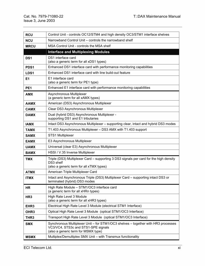
Cat. No. 7979-71080-22 T::DAX Maintenance Manual Issue 3, June 2003 RCU Control Unit - controls OC12/STM4 and high density OC3/STM1 interface shelves
NCU Narrowband Control Unit – controls the narrowband shelf
MRCU MSA Control Unit - controls the MSA shelf
Interface and Multiplexing Modules DS1 DS1 interface card
(also a generic term for all xDS1 types) PDS1 Enhanced DS1 interface card with performance monitoring capabilities
LDS1 Enhanced DS1 interface card with line build-out feature
E1 E1 interface card (also a generic term for PE1 type)
PE1 Enhanced E1 interface card with performance monitoring capabilities
AMX Asynchronous Multiplexer (a generic term for all xAMX types)
AAMX American (DS3) Asynchronous Multiplexer
CAMX Clear DS3 Asynchronous Multiplexer
DAMX Dual (hybrid DS3) Asynchronous Multiplexer - supporting DS1 and E1 tributaries
IAMX Intact DS3 Asynchronous Multiplexer – supporting clear, intact and hybrid DS3 modes
TAMX T1.403 Asynchronous Multiplexer – DS3 AMX with T1.403 support
SAMX STS1 Multiplexer
EAMX E3 Asynchronous Multiplexer
UAMX Universal (clear E3) Asynchronous Multiplexer
BAMX HSSI / V.35 Inverse Multiplexer
TMX Triple (DS3) Multiplexer Card – supporting 3 DS3 signals per card for the high density DS3 shelf (also a generic term for all xTMX types)
ATMX American Triple Multiplexer Card
ITMX Intact and Asynchronous Triple (DS3) Multiplexer Card – supporting intact DS3 or terminated (hybrid) DS3 modes
HR High Rate Module – STM1/OC3 interface card (a generic term for all xHRn types)
HR3 High Rate Level 3 Module (also a generic term for all xHR3 types)
EHR3 Electrical High Rate Level 3 Module (electrical STM1 Interface)
OHR3 Optical High Rate Level 3 Module (optical STM1/OC3 Interface)
THR3 Transport High Rate Level 3 Module (optical STM1/OC3 Interface)
SMX Synchronous Multiplexer Unit – for STM1/OC3 shelves – together with HR3 processes VC3/VC4, STS3c and STS1-SPE signals (also a generic term for MSMX type)
MSMX Multiplex/Demultiplex SMX Unit – with Transmux functionality
ECI Telecom Ltd. xi

T::DAX Maintenance Manual Cat. No. 7979-71080-22 Issue 3, June 2003 LHR Line High Rate unit - optical interface for high density STM1/OC3
(also a generic term for FLHR type) CHR High Rate unit - optical interface for high density STM1/OC3
– same as LHR with additional Transmux functionality. FLHR Far LHR module – for remote interface bays in octal configuration
SM4 Synchronous Multiplexer Level 4 – STM4/OC12 optical interface
IHR Internal High Rate module – for STM4/OC12 shelves (also a generic term for FIHR type)
MHR Internal High Rate module – for STM4/OC12 shelves – same as IHR with additional Transmux functionality.
FIHR Far IHR module – for remote interface bays in octal configuration
MIU Matrix Interface Unit – with LHR/CHR on high density STM1/OC3 shelf and with IHR/MHR on STM4/OC12 shelf - processes VC3, VC4, STS3c and STS1-SPE signals - for MSA shelves interfaces with the switching matrix
Protection Switching Modules PSW Protection Switching Unit – on DS3/E3/STS1 interface shelves
(also a generic term for TPSW type)
TPSW TAMX Protection Switching Unit
LSP Low-Speed Protection Unit – tributary protection on DS3/E3/STS1 interface shelves (also a generic term for VLSP type)
VLSP Virtual Low Speed Protection Unit
PSM Protection Switch Module – on high density DS3 shelf
TSP Tributary Signal Protection Module– on high density DS3 shelf
TRP Tributary Protection Unit– on STM1/OC3 shelf
Narrowband Shelf Modules NBU Narrowband Unit
(a generic term for all xNBU types)
ENBU European Narrowband Unit – processing 28 E1 signals
TNBU American Narrowband Unit – processing 28 T1 signals
ANBU European Narrowband Unit – supporting u-law to A-law conversion
UNBU American Narrowband Unit – supporting A-law to u-law conversion
NBX Narrowband Matrix Unit –DS0/E0 (64 kbps) cross connections
MSA Shelf Modules DHR Data High Rate module – supports FR and IP services with T1/E1, Ethernet and DS3
ATM interfaces (also a generic term for all ODHR type) ODHR Optical DHR – supporting OC3/STM1 ATM interfaces
xii ECI Telecom Ltd.

Cat. No. 7979-71080-22 T::DAX Maintenance Manual Issue 3, June 2003
TABLE OF CONTENTS
Acronyms and Abbreviations....................................................................... vii International Transmission Interfaces........................................................ viii T::DAX Modules.............................................................................................. ix
1. INTRODUCTION........................................................................................1-1 1.1. MAINTENANCE STRATEGY......................................................................... 1-1 1.2. ROUTINE MAINTENANCE ............................................................................ 1-1 1.3. T::DAX DIAGNOSTICS AND TROUBLE REPORTING ................................ 1-2 1.4. ALARM GENERATION AND CONTROL....................................................... 1-2 1.5. MAINTENANCE COMMANDS ....................................................................... 1-3 1.6. AUTOMATIC SWITCHING TO BACKUP UNITS........................................... 1-3 1.7. MODULE REPLACEMENT ............................................................................ 1-4 1.8. SYSTEM RECOVERY .................................................................................... 1-4 1.9. TECHNICAL SUPPORT................................................................................. 1-4
2. COMMON OPERATING PROCEDURES ..................................................2-1 2.1. TASK INDEX .................................................................................................. 2-1 2.2. LOG INTO T::DAX.......................................................................................... 2-2 2.3. LOG OUT OF T::DAX..................................................................................... 2-4 2.4. CANCEL AN ENTERED COMMAND............................................................. 2-5 2.5. CHANGE PASSWORD .................................................................................. 2-6
3. MAINTENANCE PROCEDURES...............................................................3-1 3.1. TASK INDEX .................................................................................................. 3-1 3.2. ROUTINE MAINTENANCE ............................................................................ 3-2
3.2.1. DATABASE BACKUP ................................................................................. 3-3 3.2.2. BACKUP USING FTP ................................................................................. 3-4 3.2.3. CLEAN THE TAPE HEADS IN THE TAPE DRIVE..................................... 3-5 3.2.4. REPLACE THE TAPE CASSETTE IN THE TAPE DRIVE ......................... 3-6 3.2.5. CLEANING THE FAN FILTERS ................................................................. 3-7
3.3. TROUBLESHOOTING.................................................................................... 3-8 3.3.1. TASK INDEX............................................................................................... 3-8 3.3.2. TROUBLESHOOTING ALARM OR EVENT MESSAGES.......................... 3-9 3.3.3. TROUBLESHOOT MODULE INDICATORS............................................. 3-15 3.3.4. TROUBLESHOOT INPUT POWER FUSES AND INDICATORS ............. 3-25
ECI Telecom Ltd. xiii
T::DAX Maintenance Manual Cat. No. 7979-71080-22 Issue 3, June 2003
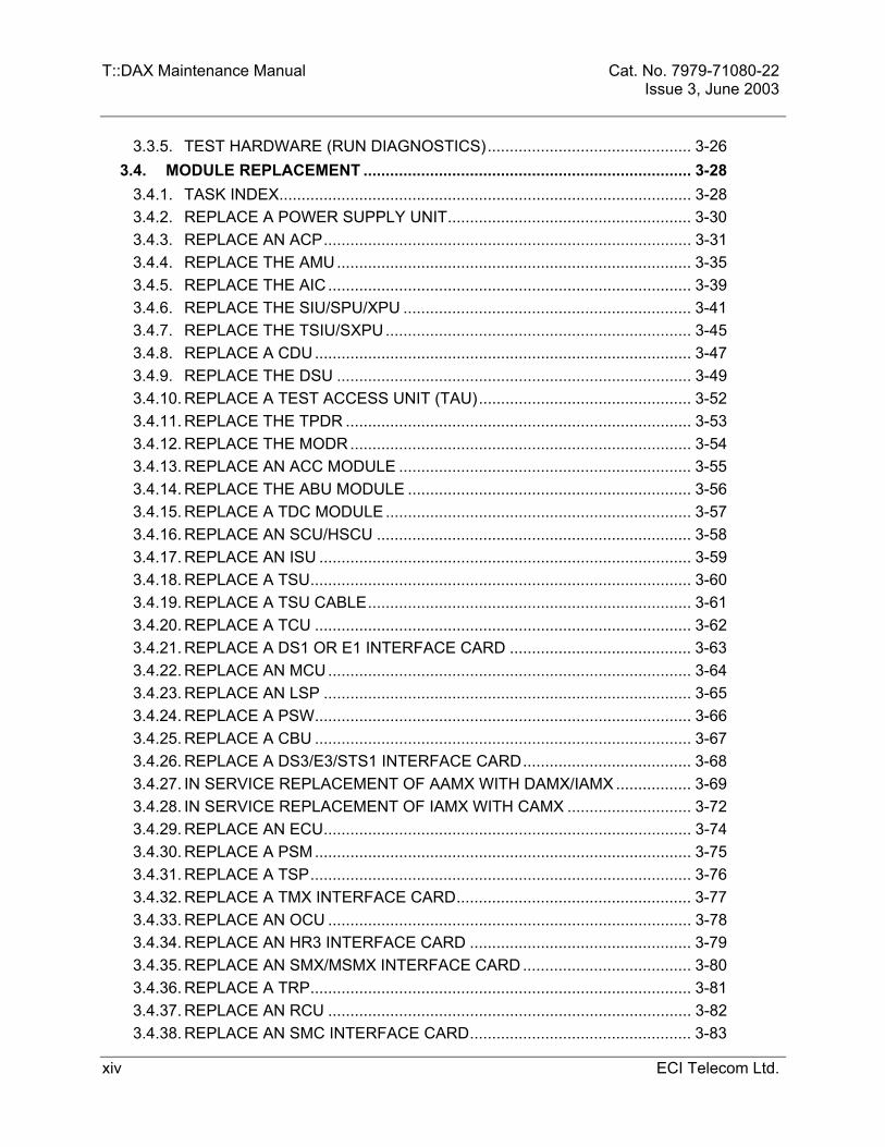
3.3.5. TEST HARDWARE (RUN DIAGNOSTICS).............................................. 3-26 3.4. MODULE REPLACEMENT .......................................................................... 3-28
3.4.1. TASK INDEX............................................................................................. 3-28 3.4.2. REPLACE A POWER SUPPLY UNIT....................................................... 3-30 3.4.3. REPLACE AN ACP................................................................................... 3-31 3.4.4. REPLACE THE AMU................................................................................ 3-35 3.4.5. REPLACE THE AIC .................................................................................. 3-39 3.4.6. REPLACE THE SIU/SPU/XPU ................................................................. 3-41 3.4.7. REPLACE THE TSIU/SXPU..................................................................... 3-45 3.4.8. REPLACE A CDU..................................................................................... 3-47 3.4.9. REPLACE THE DSU ................................................................................ 3-49 3.4.10. REPLACE A TEST ACCESS UNIT (TAU)................................................ 3-52 3.4.11. REPLACE THE TPDR .............................................................................. 3-53 3.4.12. REPLACE THE MODR............................................................................. 3-54 3.4.13. REPLACE AN ACC MODULE .................................................................. 3-55 3.4.14. REPLACE THE ABU MODULE ................................................................ 3-56 3.4.15. REPLACE A TDC MODULE..................................................................... 3-57 3.4.16. REPLACE AN SCU/HSCU ....................................................................... 3-58 3.4.17. REPLACE AN ISU .................................................................................... 3-59 3.4.18. REPLACE A TSU...................................................................................... 3-60 3.4.19. REPLACE A TSU CABLE......................................................................... 3-61 3.4.20. REPLACE A TCU ..................................................................................... 3-62 3.4.21. REPLACE A DS1 OR E1 INTERFACE CARD ......................................... 3-63 3.4.22. REPLACE AN MCU.................................................................................. 3-64 3.4.23. REPLACE AN LSP ................................................................................... 3-65 3.4.24. REPLACE A PSW..................................................................................... 3-66 3.4.25. REPLACE A CBU ..................................................................................... 3-67 3.4.26. REPLACE A DS3/E3/STS1 INTERFACE CARD...................................... 3-68 3.4.27. IN SERVICE REPLACEMENT OF AAMX WITH DAMX/IAMX ................. 3-69 3.4.28. IN SERVICE REPLACEMENT OF IAMX WITH CAMX ............................ 3-72 3.4.29. REPLACE AN ECU................................................................................... 3-74 3.4.30. REPLACE A PSM..................................................................................... 3-75 3.4.31. REPLACE A TSP...................................................................................... 3-76 3.4.32. REPLACE A TMX INTERFACE CARD..................................................... 3-77 3.4.33. REPLACE AN OCU .................................................................................. 3-78 3.4.34. REPLACE AN HR3 INTERFACE CARD .................................................. 3-79 3.4.35. REPLACE AN SMX/MSMX INTERFACE CARD ...................................... 3-80 3.4.36. REPLACE A TRP...................................................................................... 3-81 3.4.37. REPLACE AN RCU .................................................................................. 3-82 3.4.38. REPLACE AN SMC INTERFACE CARD.................................................. 3-83
xiv ECI Telecom Ltd.

Cat. No. 7979-71080-22 T::DAX Maintenance Manual Issue 3, June 2003
3.4.39. REPLACE AN LHR/CHR INTERFACE CARD.......................................... 3-84 3.4.40. REPLACE AN MIU.................................................................................... 3-85 3.4.41. REPLACE AN SM4 INTERFACE CARD .................................................. 3-86 3.4.42. REPLACE AN IHR/MHR........................................................................... 3-87 3.4.43. REPLACE AN NBU................................................................................... 3-88 3.4.44. REPLACE AN NBX................................................................................... 3-89 3.4.45. REPLACE AN NCU .................................................................................. 3-90
3.5. SYSTEM RECOVERY .................................................................................. 3-91 3.5.1. INTRODUCTION ...................................................................................... 3-91 3.5.2. TASK INDEX............................................................................................. 3-91 3.5.3. INITIALIZE A ACP .................................................................................... 3-92 3.5.4. INITIALIZE A CONTROL UNIT (XCU)...................................................... 3-93 3.5.5. INITIALIZE AN AMU ................................................................................. 3-94 3.5.6. INITIALIZE A CDU.................................................................................... 3-95 3.5.7. INITIALIZE A DSU .................................................................................... 3-96 3.5.8. INITIALIZE A TAPE .................................................................................. 3-97 3.5.9. COLD START T::DAX............................................................................... 3-98
APPENDIX A - T::DAX ERROR CODES......................................................... A-1
ECI Telecom Ltd. xv

T::DAX Maintenance Manual Cat. No. 7979-71080-22 Issue 3, June 2003
xvi ECI Telecom Ltd.

Cat. No. 7979-71080-22 T::DAX Maintenance Manual Issue 3, June 2003
1.
1.1.
1.2.
INTRODUCTION
MAINTENANCE STRATEGY T::DAX maintenance is based on the following T::DAX features:
Problem detection and reporting with built-in diagnostics
Automatic generation of appropriate alarms
Automatic or manual switching to backup units
Replacement of defective units without service interruption
Work around to clear trouble
In addition, T::DAX includes visual indicators to support on-site maintenance. These include blown fuse indications and out-of-service module indications. Visual indicators enable on-site personnel to quickly locate a defective unit for quick replacement.
ROUTINE MAINTENANCE T::DAX is engineered so that very little routine maintenance is required. Routine maintenance consists of:
Cleaning the tape heads in the tape drive
Replacing fan filters
Changing the tape on the tape drive
Note: The frequency of these actions is site-specific since it is determined by the frequency of T::DAX use. Contact your system administrator for recommended schedules for the maintenance activities.
ECI Telecom Ltd. 1-1
T::DAX Maintenance Manual Cat. No. 7979-71080-22 Issue 3, June 2003
1.3.
1.4.
T::DAX DIAGNOSTICS AND TROUBLE REPORTING T::DAX diagnostics run automatically without interfering with normal operations. In most cases, the diagnostics can isolate the problem to the replaceable module. If the specific module cannot be identified, T::DAX reports suspected trouble sources to aid manual troubleshooting. When the diagnostics detect a problem, T::DAX reports the problem and suspected source. If service will not be affected, T::DAX automatically takes the suspected unit out of service and, if necessary, activates the protection or duplex unit. The defective unit can then be replaced without affecting normal T::DAX operations. If the replacement unit passes diagnostics, T::DAX automatically puts the unit in service. You can also run diagnostics on an out-of-service unit on command. T::DAX runs the diagnostics and reports the results.
ALARM GENERATION AND CONTROL T::DAX generates the following types of alarms:
Critical alarms for failures causing a loss of service on more than 5 DS1, E1, VT1.5, VT2, VC11 or VC12 cross-connects.
Major alarms for failures causing a loss of service on any single port, tributary or cross-connect.
Major processor alarms for control system failures that disable the control capability.
Minor alarm for failures that do not affect service.
T::DAX reports these alarms in the following ways:
Alarm indicators on the TAIC front panel
Alarm messages are sent over the CIT and DTM interface links
Alarm indications are sent to central office audible and visual alarm systems and E-telemetry systems.
An audible cutoff (ACO) feature is included for silencing audible alarms and switching visual alarm indicators to an "alarm acknowledged" state. T::DAX includes a front-panel mounted ACO switch and connections for remote ACO control.
1-2 ECI Telecom Ltd.

Cat. No. 7979-71080-22 T::DAX Maintenance Manual Issue 3, June 2003
1.5.
1.6.
MAINTENANCE COMMANDS The T::DAX command set includes the following types of maintenance commands:
RTRV-COND-EQPT command displays the current condition of the equipment unit.
RMV-EQPT command removes the specified unit from service and places it in the maintenance state. This command must be executed before running diagnostics or removal of unit.
DGN-EQPT command runs a diagnostics routine on the specified equipment.
RST-EQPT command restores a specified unit to service, switching it from the maintenance state to the in-service state.
AUTOMATIC SWITCHING TO BACKUP UNITS T::DAX includes protection or duplex modules for T::DAX equipment.
• ISU and TSU modules have one “redundant” unit used as protection for all other TSU and ISU modules.
• E3/DS3/STS1 interface cards have one protection card per shelf. • SM4/LHR/CHR/THR3/EHR3/OHR3 cards work in a 1+1 equipment and facility
protection configuration. • SMX/MSMX cards have a 1:3 redundancy protection scheme. • Each pair of IHR/MHR/LHR/CHR and MIU cards has a protection pair. • Each shelf contains two load sharing power supply units (xPSU) that are both active
during normal operation, and a single unit powers the shelf if the other fails. The following are all “duplex” modules, with one unit active and one stand-by:
• Power Supply Units (xPSU) – load sharing • Admin shelf Control Processors (xACP) • Control Units (xCU) • Narrowband Matrix Units (NBX) • Clock Distribution Units (CDU) • Clock Buffer Units (CBU) • Synchronous Multiplexer and Clock unit (SMC) • Admin Communication Control unit (ACC) • PCU Bus (cables)
ECI Telecom Ltd. 1-3

T::DAX Maintenance Manual Cat. No. 7979-71080-22 Issue 3, June 2003
1.7.
1.8.
1.9.
MODULE REPLACEMENT The primary maintenance strategy for T::DAX is module replacement. In all cases (except for DS1/E1 cards), modules can easily be replaced without affecting operation of T::DAX. Module replacement consists of the following steps:
1. Check that the module is in maintenance state and out-of-service. 2. Physically remove the module from the system. 3. Install a replacement module in the system. 4. Return the module to its normal in-service state.
With the diagnostics feature turned on, the state changes are done automatically if the change is not service affecting. This makes module replacement quick and easy.
SYSTEM RECOVERY System recovery is an initialization of processor-equipped T::DAX modules. You can perform the following types of system recovery:
A warm start is initialization with a “valid” database. A warm start initializes individual modules, such as the ACP, AMU, CDU, DSU, SCU, TCU, MCU, ECU, OCU, RCU, NCU or TPDR. A warm start saves cross-connect and PM data. The database is valid after the following command is performed: INIT-SYS::AMU:ctag::0; A cold start is an initialization with a “non-valid” database. A cold start is
performed when the T::DAX is powered up, or by plugging out the AMU, disconnecting the battery jumper and plugging out the two ACPs.
TECHNICAL SUPPORT Enavis Networks Ltd. offers a full range of support services for T::DAX, including:
Remote trouble diagnosis
Software and documentation updates
Telephone assistance, including 24-hour availability of technical personnel.
Enavis Networks Ltd. offers a range of service plans to T::DAX customers. Contact your system administrator for details about specific product support services available.
1-4 ECI Telecom Ltd.

Cat. No. 7979-71080-22 T::DAX Maintenance Manual Issue 3, June 2003
2. COMMON OPERATING PROCEDURES
2.1. TASK INDEX Use the following index to find your task. If your task is not listed in the following index, refer to the Table of Contents at the beginning of this manual to locate the procedure. Note: The procedures in this section are for TL1 mode operation.
If Your Task Is To: See Section:
Log into T::DAX 2.2
Log out of T::DAX 2.3
Cancel an entered command 2.4
Change your password 2.5
ECI Telecom Ltd. 2-1

T::DAX Maintenance Manual Cat. No. 7979-71080-22 Issue 3, June 2003
2.2. LOG INTO T::DAX Note: If your T::DAX is part of an Operations Support System, use the login instructions in your OSS manuals. The instructions in the following paragraphs are not for OSS applications. To operate T::DAX you must establish communications with T::DAX and log in. You can use a variety of user/system interface (USI) devices to communicate with T::DAX. Since, in most cases, the USI device is a video terminal, this section uses the term "video terminal" instead of "USI device". You can use any VT100-compatible video terminal with T::DAX. During normal operation, you communicate with T::DAX through a communications port on the T::DAX Communication Processor Module (CPR). The CPR contains four asynchronous RS-232C ports, one X.25 port and one TCP/IP port. The RS-232C ports provide direct access or connect to modems at the T::DAX site. How you connect your video terminal to T::DAX depends on the configuration of your system. T::DAX supports the following:
Direct RS-232 cable connections
Dial-up connections using modems
Private line connections
X.25 connection
TCP/IP connection
The procedure for establishing a connection to T::DAX depends on the equipment and connection types used in your system. Contact your system administrator if you need connection instructions. The Admin shelf Interface and Control unit (AIC/TAIC) contain a Craft Interface Terminal (CIT) connector on the front panel and a DTM port (DTM-1) on the rear for emergency operation of T::DAX by trained maintenance personnel. However, the terminal can be used by local craft for normal operation of T::DAX. The T::DAX Maintenance Manual contains instructions for using the terminal with T::DAX. To operate T::DAX, you must log-in with your user ID and password. Your system administrator assigns user IDs and passwords. If you do not know your user ID or password, contact your system administrator. Use the following procedure to log-into T::DAX.
2-2 ECI Telecom Ltd.

Cat. No. 7979-71080-22 T::DAX Maintenance Manual Issue 3, June 2003 Step Logging into T::DAX
1 Establish communication with T::DAX. (The procedure for this depends on the configuration of your system.)
2 When the Admin shelf powers up, after a cold reset, the Login is allowed from the CIT and DTM-1 ports only. Only after the first Login the communication with the CPR's ports, DTM-A-1 through DTM-A-4, is allowed. After the Login, the Login screen will appear as follows: NOTICE: This is a private computer system. Unauthorized use or access may lead to prosecution.
UID: = User Identification PID: = Password DATE: = Date (format YY-MM-DD) – optional TIME: = Time of Day (format HH-MM) – optional
Contact your system administrator to obtain your UID and PID. After entering the proper data in the above fields, T::DAX will automatically revert to TL1 mode of operation. If this is the first time the PID is being used, T::DAX will force the user to change the PID before proceeding. This is to ensure password privacy.
ECI Telecom Ltd. 2-3

T::DAX Maintenance Manual Cat. No. 7979-71080-22 Issue 3, June 2003
2.3. LOG OUT OF T::DAX You must log-out when you are finished operating T::DAX. This terminates your user session and clears the port for use by other T::DAX operators. Note: T::DAX has an inactivity log-out feature that keeps track of periods of no activity at your terminal. T::DAX uses this feature to make sure you do not tie up a port by forgetting to log off. If the period of inactivity exceeds a preset time-out, T::DAX automatically logs you off. The time-out period can be set for up to 60 minutes. The inactivity log-out re can also be turned off. For information about time-out settings, contact your system administrator.
Step Logging out of T::DAX 1 To log out of T::DAX, enter the following command:
CANC-USER:[tid]:[uid]:ctag; uid - your user identification code. It must match the uid used in the login. A COMPLD message should be displayed, verifying successful log-out. If the COMPLD message does not appear, repeat the log-out procedure or contact your system administrator for additional instructions. If you are connected to the CPR through a modem, the system will automatically hang up (disconnect) the line. If you are connected through a direct connection or private line the log out will cause the log in screen to reappear.
2-4 ECI Telecom Ltd.

Cat. No. 7979-71080-22 T::DAX Maintenance Manual Issue 3, June 2003
2.4. CANCEL AN ENTERED COMMAND If you have entered a command and you wish to cancel it, you can stop the command. If you cancel the command, T::DAX does the following:
If T::DAX has not begun processing the command, T::DAX does not process the command.
If T::DAX has begun processing the command:
− For RTRV commands, the retrieval stops immediately. Data already retrieved is displayed.
− For commands with multiple AIDs, the requested action is not done on AIDs that have not been processed.
− For all other commands, the command cannot be canceled after T::DAX has begun processing it. T::DAX sends the SCNA (command not aborted) error code.
Step Canceling an Entered Command 1 To cancel an in-process command, enter the following:
ABT-CMD:[tid]::ctag::cmdctag; cmdctag - correlation tag that was entered with the command you want to cancel. The null string is valid here, to allow abortion of a command that was entered without a correlation tag. A COMPLD message should be displayed, verifying successful cancellation of the entered command. If the COMPLD message does not appear, T::DAX sends a DENY message with one of the following error codes: SCNF - T::DAX did not find a command with the cmdctag you entered.
SCNA - T::DAX could not abort the command.
ECI Telecom Ltd. 2-5

T::DAX Maintenance Manual Cat. No. 7979-71080-22 Issue 3, June 2003
2.5. CHANGE PASSWORD You should change your password at intervals recommended by your system administrator. (User passwords are also referred to as private identifiers.) Use the following procedure to change your password. The system contains a built-in password-aging feature (PAGE) that will force you to change your PID if it has not been changed during the PAGE interval. Note: This procedure is not for setting the CIT port password. This procedure applies only to passwords assigned to users.
Step Changing Your Password 1 Note: You must already be logged into T::DAX to change your password.
The next time you log in, you must use your new password. To change your password, enter: ED-SECU-PID:[tid]:uid:ctag::oldpid,newpid; uid - your user ID. oldpid - your current password. newpid - your new password (effective the next time you log-into T::DAX). After changing your password, you may want to log-out and log back in to verify your new password.
2-6 ECI Telecom Ltd.
Cat. No. 7979-71080-22 T::DAX Maintenance Manual Issue 3, June 2003
3. MAINTENANCE PROCEDURES
3.1. TASK INDEX Use the following index to find your task. If your task is not listed in the following index, refer to the index at the end of this manual to locate the procedure.
If Your Task Is To: See Section
Perform routine maintenance 3.2
Troubleshoot T::DAX equipment 3.3
Replace T::DAX modules 3.4
Perform system recovery 3.5
ECI Telecom Ltd. 3-1

T::DAX Maintenance Manual Cat. No. 7979-71080-22 Issue 3, June 2003
3.2. ROUTINE MAINTENANCE This section describes how to maintain the tape drive. Use the following index to find your task. If the task is not listed in the following index, refer to the index at the end of this manual to locate the procedure.
If Your Task Is To: See Section
Database backup 3.2.1
Clean the tape heads in the tape drive 3.2.3
Replace the tape cassette in the tape drive 3.2.4
Cleaning the fan filters 3.2.5
3-2 ECI Telecom Ltd.

Cat. No. 7979-71080-22 T::DAX Maintenance Manual Issue 3, June 2003
3.2.1. Database Backup Before making any routing maintenance or module replacement, verify that you have a back up of the system database.
Step Backing-Up The Database
1 Insert a blank tape into the TPDR.
2 Remove the TPDR from service by entering: RMV-EQPT:: TPDR:ctag::FRCD;
3 Initialize the tape by entering: INIT-SYS::TPDR:ctag::0:RUSURE=Y;
4 Restore service to the TPDR entering: RST-EQPT::TPDR:ctag;
5 Back up the database. Enter: CPY-MEM::FROMMEM=PRI,TOMEM=AUX:ctag::DATA;
6 Verify the correct database Enter: RTRV-DIR-EQPT::TPDR:CTAG; Verify the correct date and size of the recorded files
7 Label the tape: DATABASE, system id, date and time.
ECI Telecom Ltd. 3-3

T::DAX Maintenance Manual Cat. No. 7979-71080-22 Issue 3, June 2003
3.2.2. Backup Using FTP T::DAX supports File Transfer Protocol (FTP) to copy program, data, log and PM files from the T::DAX hard disk (DSU) to a remote server, and to copy program and data files from a remote server to the T::DAX hard disk (DSU). Use the following procedure to perform the File Transfer Protocol.
Step Backing-Up Using FTP
1 The FTP user in the T::DAX can to be define by using the command: SET-FTP-USER:::ctag::”uid”,”pid”; After the ctag, there are two colons and then in quotes the FTP username, a comma, and the password in quotes. This is the how the T::DAX will login to the FTP server Example: SET-FTP-USER:::ctag::”tdaxFtp”,”TDAX*3”;
2 The FTP is done in local restoration mode. To enter the local restoration mode use the command: STA-LOCL-RST:::ctag;
3 To copy files from the T::DAX disk, use the command: CPY-MEM::FROMMEM=SEC,TOMEM=”<destination_ip_address>” :ctag::<memusage>:NAME=name,RUSURE=Y; <destination_ip_address> - Must be in quotes and must be the address of the FTP server that you want to transfer the information to. <memusage> - Can be DATA, NBDATA, LOG, PM, PGM NAME – The directory name.
4 To copy files from the FTP server to the T::DAX disk, use the following command: CPY-MEM::FROMMEM=”<destination_ip_address>”, TOMEM=SEC:ctag::<memusage>:NAME=name,RUSURE=Y;
5 To exit the local restoration mode, use the command: EXIT-LOCL-RST:::ctag;
3-4 ECI Telecom Ltd.

Cat. No. 7979-71080-22 T::DAX Maintenance Manual Issue 3, June 2003 3.2.3. Clean the Tape Heads in the Tape Drive Clean the tape heads yearly. For this procedure you need the following kit:
3M Tape Head Cleaner Kit
If another type of head cleaner is used, follow the instructions provided with the head cleaner kit.
Step Cleaning Tape Heads in the Tape Drive
1 Remove the tape from the tape drive. (Refer to the cleaning instructions located on the inside cover of the tape cleaner case.)
2 Remove the tape head cleaner from its case and moisten the cleaning pad evenly with 15 drops of cleaning fluid.
3 Insert the key actuator into the hole in the side of the cleaner.
4 Insert the head cleaner inside the drive and secure in place.
5 Push lever handle 15 times. Tape heads are now clean.
6 Unlock drive and remove the head cleaner.
7 Remove the used cleaning pad and discard it. (Use a cleaning pad only once).
8 Replace the cleaning pad with a new one. (New cleaning pads are stored in the tape drive cleaner case).
ECI Telecom Ltd. 3-5

T::DAX Maintenance Manual Cat. No. 7979-71080-22 Issue 3, June 2003
3.2.4. Replace and Initialize the Tape Cassette / Magneto Optical Disk Under normal conditions, the tape cassette / magneto optical disk is used for database backup and replaced each time the database is backed up. Perform the following procedure to replace the cassette / optical disk in the drive. Note: There are two types of tape drives: Big (3M) and Small (Seagate). Step Replacing Tape Cassette / Magneto Optical Disk
1 Tape: Wait until the tape is not running and slide the tape drive lock up to release the tape cassette from the drive (In the small Seagate tape drive there is no tape lock.).
Pull the tape cassette from the tape drive.
Disk: Push the button to eject the optical disk from the drive.
Note: The TPDR will be in OOS state until a new cassette / disk is reinserted.
2 Tape: Verify that the new tape cassette is not “write protected”.
Put the new tape cassette into the tape drive, positioning the cassette with the exposed tape at the top of the cassette and the metallic side facing the LEDs on the tape drive. (See Figure 3-1) In the small Seagate tape, the metallic side is facing the ACP card.
Hold the cassette in place with one hand and slide the lock over the cassette with the other hand. (In the small Seagate tape drive there is no tape lock – just push the tape into place.)
Disk: Insert the new optical disk into the drive.
3 The tape cassette / magneto optical disk must be initialized for use.
Enter the following commands:
RMV-EQPT::TPDR:ctag::FRCD; INIT-SYS::TPDR:ctag::0:RUSURE=Y; RST-EQPT::TPDR:ctag;
3-6 ECI Telecom Ltd.

Cat. No. 7979-71080-22 T::DAX Maintenance Manual Issue 3, June 2003
Figure 3-1. Big Tape Drive Installation
TOP
METALLIC SIDE
3.2.5. Cleaning the Fan Filters Fans are installed in the Admin shelf, STM1/OC3 shelves and High Density DS3 shelves. Under normal conditions, the fan filters should be cleaned quarterly. Perform the following procedure to clean the fan filters.
Step Cleaning the Fan Filters 1 With the clips on the side of the fan filter above and below the shelf, remove
the filter from the shelf.
2 Clean the filter with compressed air or water and let dry.
3 Replace the fan filter in its place with the clips on its sides.
ECI Telecom Ltd. 3-7

T::DAX Maintenance Manual Cat. No. 7979-71080-22 Issue 3, June 2003
3.3. TROUBLESHOOTING
3.3.1.
Troubleshooting is simple with T::DAX’s built-in diagnostics, automatic trouble reporting, and module indicators. There are several different ways to troubleshoot T::DAX. You can troubleshoot in response to any of the following:
Alarm or event messages
Module indicators
Blown fuse indications
Automatic and manual diagnostic reports
Work around to clear trouble.
Troubleshooting procedures for each of these methods are provided in this section.
Task Index Use the following index to find your task. Note: Except for troubleshooting fuses and loss of power indications, you must be logged onto T::DAX before using the procedures in the following index. If you need information about logging on, refer to Section 1, Common Operating Procedures.
If Your Task Is To: See Section
Troubleshoot alarm or event messages (REPT ALM or REPT EVT)
3.3.2
Troubleshoot module indicators 3.3.3
Troubleshoot blown fuse and loss of power indicators
3.3.4
Test hardware (run diagnostics) 3.3.5
3-8 ECI Telecom Ltd.

Cat. No. 7979-71080-22 T::DAX Maintenance Manual Issue 3, June 2003
3.3.2. Troubleshooting Alarm or Event Messages T::DAX generates alarm or event messages when it detects an equipment, cross-connect or facility problem. The messages are displayed on terminals of users logged into T::DAX. The messages are also sent to the printers (if a printer is connected to T::DAX) and stored on the log file on the hard disk (if activated). The log file can be viewed on the terminal or printed. The log interval can be set by a software command to store for up to 30 days. These messages alert you to the possible need for corrective action. They contain information that helps you locate the problem that caused the alarm. Alarm messages also activate central office alarms that are visually shown on the AIC on the Admin shelf, on the CO alarm system and a remote alarm system through dry contact relays. Alarm messages begin with REPT ALM and identify problems that need immediate attention. Event messages begin with REPT EVT and identify problems that do not cause alarms but may require corrective action. When an alarm or event is cleared, T::DAX reports the clearing with another REPT ALM or EVT message. Additional important information is displayed in the “free text” field of the alarm report. This text appears only in the Alarm/Event report and not in the response to “RTRV-ALM” command. In order to see this text, retrieve the LOG file. Use the following procedure to troubleshoot a problem reported by an alarm or event message.
Step Troubleshooting an Equipment Alarm or Event Message 1 Check the message to determine if an equipment, facility, or cross-connect
failure occurred: • REPT-ALM/EVT-EQPT is an equipment alarm or event. Continue with
step 2. • REPT-ALM-xx (where xx = E1, E2, E3, T1, T2, T3, VT1, VT2, STS1,
STS3c, OC3, VC11, VC12, VC3, VC4, STM1, OC12 or STM4) is a facility alarm. The alarm is not due to T::DAX equipment failure. Facility trouble-shooting is required. Refer to the facility maintenance instructions in the T::DAX Operation and Administration Manual.
2 Check the SRVEFF (Service Effect) field in the message for one of the following indications: SA - service-affecting NSA - not service-affecting
If the alarm is service affecting, immediate action is required.
ECI Telecom Ltd. 3-9

T::DAX Maintenance Manual Cat. No. 7979-71080-22 Issue 3, June 2003
Step Troubleshooting an Equipment Alarm or Event Message 3 Check entries in the following fields to determine the equipment associated with
the message and the status of automatic diagnostics. • The aid (access identifier) field at the beginning of the third line of the
message will tell you what type of equipment is involved. • The TBLISLT (trouble isolation) field at the end of the message. ISO = Isolated, the aid is a replaceable unit.
NIPSS = Not isolated, all diagnostics passed. The aid reports suspected units. NIMAN = Not isolated. Isolation must be performed manually. Suspected units are identified in the aid. DGN = Automatic diagnostics are in progress. Wait for a separate message with diagnostics results. No entry – Trouble isolation by T::DAX is not applicable to the alarm condition.
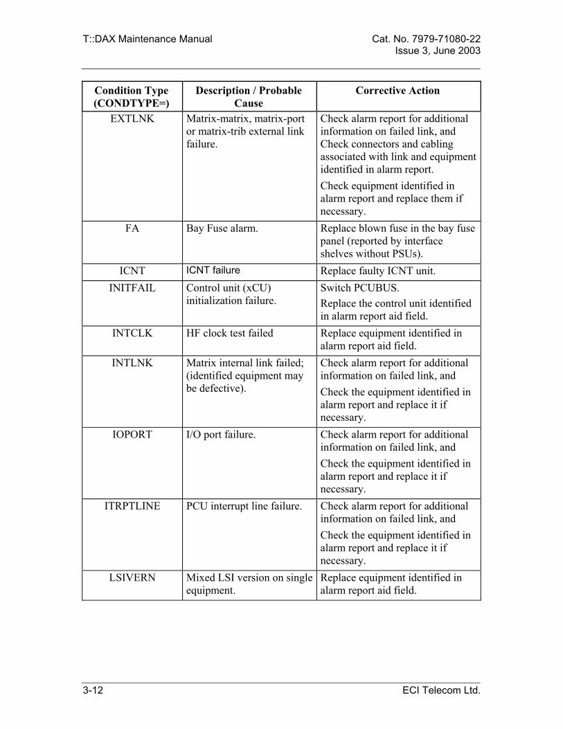
4 Check the message CONDTYPE = field and take corrective action listed in Table 3-1. (If corrective action clears the alarm or event, T::DAX generates an alarm or event message. The message includes the AID of the associated equipment and NTFCNCDE=CL.) The bay and shelf of the faulty unit are reported in the alarm message.
5 Verify the current status of the alarm or event by entering: RTRV-COND-EQPT:[tid]:aid:ctag; If the response is 0 RECORDS RETRIEVED, corrective action cleared the alarm or event. If the response indicates an alarm condition, corrective action did not clear the alarm or event. Repeat steps 4 and 5 for each corrective action listed in Table 3-1 for the CONDTYPE entry. If all listed corrective actions have been done and the alarm or event is not cleared, technical assistance is required. Contact your system administrator or Enavis Networks Technical Support for further instructions.
3-10 ECI Telecom Ltd.

Cat. No. 7979-71080-22 T::DAX Maintenance Manual Issue 3, June 2003 Table 3-1 Corrective Action for Equipment Alarm and Event Messages
Condition Type (CONDTYPE=)
Description / Probable Cause
Corrective Action
ABLINE PCU AB line failure. Check AB line connections. Replace AIC Replace AB line
BATT AMU battery failure. Replace AMU battery.
BKUPMEMA Auxiliary (tape/magneto disk) backup memory failure.
Replace tape drive / magneto optical drive.
BKUPMEMP Primary nonvolatile backup memory failure.
Replace AMU.
BKUPMEMS Secondary (disk) backup memory failure.
Replace hard disk.
CLK37MHZ AMX 37 megahertz clock failure.
Replace equipment identified in alarm message aid field.
CLK45MHZ AMX 45 megahertz clock failure.
Replace equipment identified in alarm message aid field.
CNVT+FA Power converter failure or fuse alarm.
Replace PSU identified in alarm report, or replace blown fuse in the bay fuse panel.
COMPONTF AMX failure. Replace equipment identified in alarm message aid field.
CONTCOM No communication with communication processor.
Check alarm report for additional information on failed link, and Check equipment identified in alarm report and replace it if necessary.
CONTR Control processor (ACP) failure.
Replace the ACP module.
CONTRDUP
Duplex control processor (ACP) failure.
Perform “INIT-SYS” to the standby ACP. If the problem is not solved, replace the standby ACP
DS3LOS DS3 Rx loss of signal. Replace equipment identified in alarm message aid field.
ECI Telecom Ltd. 3-11
T::DAX Maintenance Manual Cat. No. 7979-71080-22 Issue 3, June 2003
Condition Type (CONDTYPE=)
Description / Probable Cause
Corrective Action
EXTLNK Matrix-matrix, matrix-port or matrix-trib external link failure.
Check alarm report for additional information on failed link, and Check connectors and cabling associated with link and equipment identified in alarm report. Check equipment identified in alarm report and replace them if necessary.
FA Bay Fuse alarm. Replace blown fuse in the bay fuse panel (reported by interface shelves without PSUs).
ICNT ICNT failure Replace faulty ICNT unit. INITFAIL Control unit (xCU)
initialization failure. Switch PCUBUS. Replace the control unit identified in alarm report aid field.
INTCLK HF clock test failed Replace equipment identified in alarm report aid field.
INTLNK Matrix internal link failed; (identified equipment may be defective).
Check alarm report for additional information on failed link, and Check the equipment identified in alarm report and replace it if necessary.
IOPORT
I/O port failure. Check alarm report for additional information on failed link, and Check the equipment identified in alarm report and replace it if necessary.
ITRPTLINE PCU interrupt line failure. Check alarm report for additional information on failed link, and Check the equipment identified in alarm report and replace it if necessary.
LSIVERN Mixed LSI version on single equipment.
Replace equipment identified in alarm report aid field.
3-12 ECI Telecom Ltd.

Cat. No. 7979-71080-22 T::DAX Maintenance Manual Issue 3, June 2003
Condition Type (CONDTYPE=)
Description / Probable Cause
Corrective Action
MISMEQPT Physical equipment does not match assignment.
Replace the equipment with the matching assignment equipment. Verify that the unit is properly provisioned and entered into the system database.
MTXSGNL Signal failed on matrix link. Check alarm report for additional information on failed link, and Check connectors and cabling associated with link and equipment identified in alarm report. Check equipment identified in alarm report and replace it if necessary.
PAPEROUT Printer out of paper Refill printer paper. PCUBUSF
PCU-ACP bus failure. Check connectors and cabling
associated with equipment identified in alarm report. Tighten connectors or replace defective cables as necessary.
PGMMEM Program memory failure (ROM).
Replace ACP.
PLUGIN Equipment was plugged in. This condition is reported after module replacement. No corrective action needed.
PLLFLR PLL failure Replace CDU. PLUGOUT The card was plugged out.
This condition is also reported in case of card total failure.
This condition is reported during module replacement or in case total card failure (like a blown fuse in the card). It should clear when the replacement equipment is plugged in. Plug in or replace card.
PRGRM Equipment programming failure.
Replace equipment identified in alarm report aid field. Load program.
PRINTERF Printer failure. Repair or replace printer. PROFFLN Printer off line. Set printer on line.
ECI Telecom Ltd. 3-13

T::DAX Maintenance Manual Cat. No. 7979-71080-22 Issue 3, June 2003
Condition Type (CONDTYPE=)
Description / Probable Cause
Corrective Action
PRTLEXTLNK Matrix-matrix external link partial failure.
Replace equipment identified in alarm report aid field.
RCVRY Recovery has been initiated. No corrective action needed. RTCLK Real time clock failure. Check alarm report for additional
information on failed link, and Check equipment identified in alarm report and replace it if necessary.
RXSGNL Port receive signal failed. Replace equipment cross-connected with identified equipment in alarm report aid field.
SENSOR5V AMX 5 volt sensor failure. Replace equipment identified in alarm report aid field.
SNGLLSI One or more LSIs failed. Replace equipment identified in alarm message aid field.
STS1LOS STS1 Rx loss of signal. Replace equipment identified in alarm aid field.
SYNC Synchronization failure Check alarm report for additional information on the failed link, and Check equipment identified in alarm report and replace it if necessary.
TCNT TCNT failure Replace faulty TCNT unit. TIMINGCABLEFLR Timing cable failure Replace the cable.
TXSGNL Port transmit signal failure. Replace card identified in alarm message aid field.
WKGMEM
Working memory failure (RAM).
Replace ACP identified in alarm message aid field.
3-14 ECI Telecom Ltd.

Cat. No. 7979-71080-22 T::DAX Maintenance Manual Issue 3, June 2003
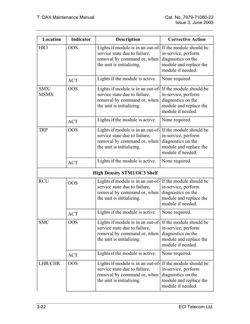
3.3.3. Troubleshoot Module Indicators T::DAX modules include indicators that can help on-site personnel identify the source of a problem. The indicators are, in most cases, a way of quickly locating equipment reported by T::DAX as faulty. Keep in mind that these indications do not always indicate a problem. Before troubleshooting a visual indication, be sure to contact your system administrator. Refer to Table 3-2 for descriptions of module indicators and appropriate corrective action. Note: For complete descriptions of module controls, indicators, and connectors, refer to the T::DAX Reference Manual.
Table 3-2. Descriptions of Module Indicators
Location Indicator Description Corrective Action
Switching Matrix Shelf
ISU/HISU OOS Lights if module is in an out-of-service state due to failure, removal by command or, when the unit is initializing.
If the module should be in-service, perform diagnostics on the module and replace the module if needed.
SCU/ HSCU OOS Lights if module is in an out-of-service state due to failure, removal by command or, when the unit is initializing.
If the module should be in-service, perform diagnostics on the module and replace the module if needed.
TSU OOS Lights if TSU is out of service, providing front panel indication of the TSU condition. (TSUs are mounted on the rear of the bay).
If applicable, perform diagnostics on TSU. Replace if necessary.
SPSU / HPSU OOS
Lights if SPSU / HPSU is out of service, providing front panel indication of the SPSU/ HPSU condition. (mounted on the rear of the bay).
If applicable, perform diagnostics on SPSU/ HPSU. Replace if necessary.
ECI Telecom Ltd. 3-15

T::DAX Maintenance Manual Cat. No. 7979-71080-22 Issue 3, June 2003
Location Indicator Description Corrective Action
TSU OOS Lights if module is in an out-of-service state due to failure, removal by command or, when the unit is initializing.
If the module should be in-service, perform diagnostics on the module and replace the module if needed.
SPSU/ HPSU
ON Lights if module is active. Both modules in a shelf are active during normal operation.
None required.
FLR
Lights if the module failed. Perform diagnostics on the module. Replace the module.
Admin Shelf
ACP OOS Lights if module is in an out-of-service state due to failure, removal by command or, when the unit is initializing.
If the module should be in-service, perform diagnostics on the module and replace the module if needed.
ACT Lights if the module is active. None required.
LOAD Lights when software or database information is being loaded into the ACP.
None required.
AMU /TAMU /HAMU
OOS Lights if module is in an out-of-service state due to failure, removal by command or, when the unit is initializing.
If the module should be in-service, perform diagnostics on the module and replace the module if needed.
(T)AIC OOS Lights if module is in an out-of-service state due to failure, removal by command or, when the unit is initializing.
If the module should be in-service, perform diagnostics on the module and replace the module if needed.
CRIT Lights if a failure occurs that causes loss of service on more than 5 cross-connects, loss of power by the system or trouble conditions as specified in Reference Manual.
Determine cause of alarm by entering RTRV-ALM command. Refer to Operation and Administration Manual for facility information.
3-16 ECI Telecom Ltd.

Cat. No. 7979-71080-22 T::DAX Maintenance Manual Issue 3, June 2003
Location Indicator Description Corrective Action
MAJOR Lights if a failure occurs that causes loss of service in any cross-connection or trouble conditions as specified in Reference Manual.
Determine cause of alarm by entering RTRV-ALM command. Refer to Operation and Administration Manual for facility information.
PROC Lights if a control system failure disables the T::DAX control capability for a shelf or the system.
Perform diagnostics on the PCU causing alarm. Switch to duplex PCU and either perform recovery procedures or replace the PCU.
MINOR Lights if a failure occurs that does not cause loss of service.
Determine cause of alarm by entering RTRV-ALM command.
ACO Lights when audible cutoff is activated and alarm condition exist. It remains lit until existing alarms are cleared or a new alarm occurs.
None required.
CDU OOS Lights if module is in an out-of-service state due to failure, removal by command or, when the unit is initializing.
If the module should be in-service, perform diagnostics on the module and replace the module if needed.
ACT Lights if the module is active. None required.
TSIU PWR FLR Lights to indicate a failure on the modules.
Perform diagnostics on the module. Replace if necessary.
SXPU CHS Lights to indicate a halt condition from the processor
None required.
BFL Lights when there is a Board Failure.
Perform diagnostics on the module. Replace if necessary.
CPU Lights when the processor bus is active.
None required.
PCI Lights when the PCI bus is active.
None required.
ECI Telecom Ltd. 3-17

T::DAX Maintenance Manual Cat. No. 7979-71080-22 Issue 3, June 2003
Location Indicator Description Corrective Action
FUS Lights when all the board power is working (always on).
If off, perform diagnostics on the module. Replace if necessary.
SYS Lights when the VMEbus is active.
None required.
SIU Red power failure indicators:
- SIU - SPU - XPU
Lights to indicate a power failure on the SIU, SPU or XPU modules.
Perform diagnostics on the module. Replace if necessary.
SPU STAT Lights when the SPU processor has halted.
None required.
RUN Lights when the stored program is running.
None required.
SCON Lights to indicate that the SPU is the system controller.
None required.
DSU HDD Hard disk indicator. None required.
TPDR GREEN LED
Lights when tape drive is running.
None required.
APSU ON Lights if module is active. Both modules in a shelf are active during normal operation.
None required.
FLR Lights if the module failed. Perform diagnostics on the module. Replace the module.
DS1/E1 Shelf
TCU OOS Lights if module is in an out-of-service state due to failure, removal by command or, when the unit is initializing.
If the module should be in-service, perform diagnostics on the module and replace the module if needed.
ACT Lights if the module is active. None required.
3-18 ECI Telecom Ltd.

Cat. No. 7979-71080-22 T::DAX Maintenance Manual Issue 3, June 2003
Location Indicator Description Corrective Action
DS1 and E1 Interface Cards
Red LED Lights when card is out of service, due to failure or removed by command.
Perform diagnostics on DS1/E1 Interface card and replace if necessary.
PSU ON Lights if module is active. Both modules in a shelf are active during normal operation.
None required.
FLR Lights if the module failed. Perform diagnostics on the module. Replace the module.
DS3/E3/STS1 Shelf
MCU OOS Lights if module is in an out-of-service state due to failure, removal by command or, when the unit is initializing.
If the module should be in-service, perform diagnostics on the module and replace the module if needed.
ACT Lights if the module is active. None required.
CBU OOS Lights if module is in an out-of-service state due to failure, removal by command or, when the unit is initializing.
If the module should be in-service, perform diagnostics on the module and replace the module if needed.
ACT Lights if the module is active. None required.
AMX OOS Lights if module is in an out-of-service state due to failure, removal by command or, when the unit is initializing.
If the module should be in-service, perform diagnostics on the module and replace the module if needed.
ACT Lights if the module is active. None required.
PSW OOS Lights if module is in an out-of-service state due to failure, removal by command or, when the unit is initializing.
If the module should be in-service, perform diagnostics on the module and replace the module if needed.
TACC Lights if Test Access is being performed on one of the signals.
None required.
ECI Telecom Ltd. 3-19

T::DAX Maintenance Manual Cat. No. 7979-71080-22 Issue 3, June 2003
Location Indicator Description Corrective Action
PROT AMX-A to AMX-H
Lights when AMX in slots AMX-A through AMX-H is switched to protection.
None required.
VLSP OOS Lights if module is in an out-of-service state due to failure, removal by command or, when the unit is initializing.
If the module should be in-service, perform diagnostics on the module and replace the module if needed.
ACT Lights if the module is active. None required.
PSU ON Lights if module is active. Both modules in a shelf are active during normal operation.
None required.
FLR
Lights if the module failed. Perform diagnostics on the module. Replace the module.
High Density DS3 Shelf
ECU OOS Lights if module is in an out-of-service state due to failure, removal by command or, when the unit is initializing.
If the module should be in-service, perform diagnostics on the module and replace the module if needed.
ACT Lights if the module is active. None required.
TMX OOS Lights if module is in an out-of-service state due to failure, removal by command or, when the unit is initializing.
If the module should be in-service, perform diagnostics on the module and replace the module if needed.
ACT Lights if the module is active. None required.
TSP OOS Lights if module is in an out-of-service state due to failure, removal by command or, when the unit is initializing.
If the module should be in-service, perform diagnostics on the module and replace the module if needed.
ACT Lights if the module is active and one of the TMX card is under protection.
Replace the faulty TMX.
3-20 ECI Telecom Ltd.

Cat. No. 7979-71080-22 T::DAX Maintenance Manual Issue 3, June 2003
Location Indicator Description Corrective Action
PSM-A OOS Lights if module is in an out-of-service state due to failure, removal by command or, when the unit is initializing.
If the module should be in-service, perform diagnostics on the module and replace the module if needed.
ACT PSM-A provides the timing clock to the TMX cards.
None required.
PROT Lights if one of the TMX-A through TMX-H is under protection.
Replace the faulty TMX.
TACC Lights if one of the DS3 signals in TMX-A through TMX-H is being tested via the TACC.
None required.
PSM-B OOS Lights if module is in an out-of-service state due to failure, removal by command or, when the unit is initializing.
If the module should be in-service, perform diagnostics on the module and replace the module if needed.
ACT PSM-B provides the timing clock to the TMX cards.
None required.
PORT Lights if one of the TMX-A through TMX-H is under protection.
Replace the faulty TMX.
TACC Lights if one of the DS3 signals in TMX-A through TMX-H is being tested via the TACC.
None required.
STM1/OC3 Shelf
OCU OOS Lights if module is in an out-of-service state due to failure, removal by command or, when the unit is initializing.
If the module should be in-service, perform diagnostics on the module and replace the module if needed.
ACT Lights if the module is active. None required.
ECI Telecom Ltd. 3-21
T::DAX Maintenance Manual Cat. No. 7979-71080-22 Issue 3, June 2003
Location Indicator Description Corrective Action
HR3 OOS Lights if module is in an out-of-service state due to failure, removal by command or, when the unit is initializing.
If the module should be in-service, perform diagnostics on the module and replace the module if needed.
ACT Lights if the module is active. None required.
SMX/ MSMX
OOS Lights if module is in an out-of-service state due to failure, removal by command or, when the unit is initializing.
If the module should be in-service, perform diagnostics on the module and replace the module if needed.
ACT Lights if the module is active. None required.
TRP OOS Lights if module is in an out-of-service state due to failure, removal by command or, when the unit is initializing.
If the module should be in-service, perform diagnostics on the module and replace the module if needed.
ACT Lights if the module is active. None required.
High Density STM1/OC3 Shelf
RCU OOS Lights if module is in an out-of-service state due to failure, removal by command or, when the unit is initializing.
If the module should be in-service, perform diagnostics on the module and replace the module if needed.
ACT Lights if the module is active. None required.
SMC OOS Lights if module is in an out-of-service state due to failure, removal by command or, when the unit is initializing.
If the module should be in-service, perform diagnostics on the module and replace the module if needed.
ACT Lights if the module is active. None required.
LHR/CHR OOS Lights if module is in an out-of-service state due to failure, removal by command or, when the unit is initializing.
If the module should be in-service, perform diagnostics on the module and replace the module if needed.
3-22 ECI Telecom Ltd.

Cat. No. 7979-71080-22 T::DAX Maintenance Manual Issue 3, June 2003
Location Indicator Description Corrective Action
ACT Lights if the module is active. None required.
MIU OOS Lights if module is in an out-of-service state due to failure, removal by command or, when the unit is initializing.
If the module should be in-service, perform diagnostics on the module and replace the module if needed.
ACT Lights if the module is active. None required.
STM4/OC12 Shelf
RCU OOS Lights if module is in an out-of-service state due to failure, removal by command or, when the unit is initializing.
If the module should be in-service, perform diagnostics on the module and replace the module if needed.
ACT Lights if the module is active. None required.
SM4 OOS Lights if module is in an out-of-service state due to failure, removal by command or, when the unit is initializing.
If the module should be in-service, perform diagnostics on the module and replace the module if needed.
ACT Lights if the module is active. None required.
IHR/MHR OOS Lights if module is in an out-of-service state due to failure, removal by command or, when the unit is initializing.
If the module should be in-service, perform diagnostics on the module and replace the module if needed.
ACT Lights if the module is active. None required.
MIU OOS Lights if module is in an out-of-service state due to failure, removal by command or, when the unit is initializing.
If the module should be in-service, perform diagnostics on the module and replace the module if needed.
ACT Lights if the module is active. None required.
ECI Telecom Ltd. 3-23
T::DAX Maintenance Manual Cat. No. 7979-71080-22 Issue 3, June 2003
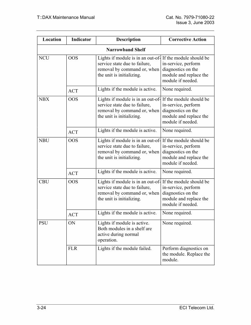
Location Indicator Description Corrective Action
Narrowband Shelf
NCU OOS Lights if module is in an out-of-service state due to failure, removal by command or, when the unit is initializing.
If the module should be in-service, perform diagnostics on the module and replace the module if needed.
ACT Lights if the module is active. None required.
NBX OOS Lights if module is in an out-of-service state due to failure, removal by command or, when the unit is initializing.
If the module should be in-service, perform diagnostics on the module and replace the module if needed.
ACT Lights if the module is active. None required.
NBU OOS Lights if module is in an out-of-service state due to failure, removal by command or, when the unit is initializing.
If the module should be in-service, perform diagnostics on the module and replace the module if needed.
ACT Lights if the module is active. None required.
CBU OOS Lights if module is in an out-of-service state due to failure, removal by command or, when the unit is initializing.
If the module should be in-service, perform diagnostics on the module and replace the module if needed.
ACT Lights if the module is active. None required.
PSU ON Lights if module is active. Both modules in a shelf are active during normal operation.
None required.
FLR
Lights if the module failed. Perform diagnostics on the module. Replace the module.
3-24 ECI Telecom Ltd.

Cat. No. 7979-71080-22 T::DAX Maintenance Manual Issue 3, June 2003
3.3.4. Troubleshoot Input Power Fuses and Indicators Located at the top of each bay, the fuse panel contains fuses and blown fuse indicators for A and B -48 Vdc input power. A and B input power connects to a terminal strip on the rear of the panel. The following fuses and indicators are located at the top of each bay for each of the A and B feeds:
• FUSE ALARM indicator - Lights if fuse blows (MAIN, SENSE, F1, F2, F3, or F4)
• MAIN fuse - Provides overload protection on the feed input to the bay. For interface bays and for basic, double and quad switching network bays – 30A For switching network bays in octal configurations – 50A
• SENSE fuse (1-1/3 A) - Activates the fuse alarm if the main fuse blows.
• Fuses F1, F2, F3, and F4 - Provides overload protection to the shelves. The fuse designation depends on configuration and bay type as detailed in Table 3-3 below. For interface bays and for basic, double and quad switching network bays – 10A For switching network bays in octal configurations – 15A
Table 3-3. Input Power Fuses and Indicators
Bay Fuse Designation Switching Network Bays Basic/double configurations
F1 – switching network shelf F2 – Admin shelf (on 2nd bay in double configuration - not used) F3 – 2nd from top interface shelf F4 – top interface shelf
Switching Network Bays Quad configurations
F1 – bottom switching network shelf F2 – top switching network shelf F3 – Admin shelf / ABA-A card F4 – not used / ABA-B card
Switching Network Bays Octal configurations
F1 – bottom switching network shelf F2 – top switching network shelf F3 – Admin shelf / TDU shelf / COMM shelf F4 – HFAN
Type I Interface Bay F1 – Not used F2 – bottom interface shelf F3 – middle interface shelf F4 – top interface shelf
Type II Interface Bay F1 – bottom interface shelf F2 – 2nd from bottom interface shelf F3 – 3rd from bottom interface shelf F4 – top interface shelf
ECI Telecom Ltd. 3-25

T::DAX Maintenance Manual Cat. No. 7979-71080-22 Issue 3, June 2003
3.3.5. Test Hardware (Run Diagnostics) T::DAX includes a diagnostics feature that can detect hardware problems. T::DAX is programmed to automatically run diagnostics periodically. You can also run diagnostics on demand. T::DAX tests the specified equipment and reports the results. The procedure for replacing specific units is presented in the following section 3.3. The diagnostics are run on each unit during these procedures.
Step Testing Hardware with Diagnostics 1 To run diagnostics, the equipment to be tested must be in a maintenance state.
To display the current state of the equipment, enter: RTRV-COND-EQPT:[tid]:aid:ctag; Check the response to determine whether the equipment is in or out of service. Use the following example response as a guide to locate the equipment state in the response. <cr><lf><lf> sid YY-MM-DD HH:MM:SS <cr><lf> M ctag RTRV <cr><lf> “[aid],[aidtype]:[ntfcncde],typerep [,typerepleft][,typerepright] [srveff],[proteqpt]”<cr><lf>; Refer to Appendix B, T::DAX I/O Messages for ntfcncde typerep, srveff and proteqpt definitions.
2 If the equipment is In-Service (IS), place it in a Maintenance (MT) state by using the following command: RMV-EQPT:[tid]:aid:ctag::[mode]:[INCL=incl],[RUSURE=rusure]; mode - specifies how the specified equipment will be removed from service. NORM - (default) Removal request will be executed only if the removal will not cause interruption of service. Otherwise, the remove request will be denied. FRCD - Remove request will be executed with no regard to service interruption.incl - Confirmation field; relevant for DS1/E1 port, AMX or SMX. Enter Y to remove even if the port or any of its tributaries is part of a red-lined connection, subject to mode, or enter N (default) to remove only if neither the port nor any of its tributaries is part of a red-lined connection, subject to mode. rusure - Confirmation field; relevant for ACP and PCU types. Enter Y to remove the equipment unconditionally, or N (default) to deny the command if the request will remove an active processor.
3-26 ECI Telecom Ltd.

Cat. No. 7979-71080-22 T::DAX Maintenance Manual Issue 3, June 2003
Step Testing Hardware with Diagnostics 3 To run diagnostics, enter:
DGN-EQPT:[tid]:aid:ctag; The response reports PASS (the equipment is operational) or FAIL (the equipment must be replaced. Refer to Module Replacement Procedures).
4 To return the equipment to an in-service state, enter: RST-EQPT:[tid]:aid:ctag::[mode]; mode - the mode in which the command is implemented:
NORM - Normal (default) - The unit is returned to service only if it is in a good working condition, as verified by T::DAX. Otherwise, the request is denied. FRCD – Forced - The unit is returned to service regardless of its condition.
ECI Telecom Ltd. 3-27

T::DAX Maintenance Manual Cat. No. 7979-71080-22 Issue 3, June 2003
3.4.
3.4.1.
MODULE REPLACEMENT
Task Index Use the following index to find your task. If the task is not listed in the following index, refer to the index at the end of this manual to locate the procedure.
If Your Task Is To Replace: See Section
Admin Shelf: APSU 3.4.2 xACP 3.4.3 xAMU 3.4.4 AIC/TAIC 3.4.5 CDU 3.4.6 TSIU/SXPU 3.4.7 SIU/SPU/XPU 3.4.8 DSU 3.4.9 Test Access Unit (TAU) 3.4.10 TPDR 3.4.11 MODR 3.4.12 ACC 3.4.13 ABU 3.4.14 TDC 3.4.15
Switching Network Shelf: SPSU / HPSU 3.4.2 SCU / HSCU 3.4.16 ISU / HISU 3.4.17 TSU 3.4.18 TSU cable 3.4.19
DS1/E1 Shelf: PSU 3.4.2 TCU 3.4.20 DS1 or E1 Interface Card 3.4.21
DS3/E3/STS1 Shelf: PSU 3.4.2
3-28 ECI Telecom Ltd.

Cat. No. 7979-71080-22 T::DAX Maintenance Manual Issue 3, June 2003
If Your Task Is To Replace: See Section MCU 3.4.22 VLSP 3.4.23 PSW 3.4.24 CBU 3.4.25 DS3/E3/STS1 Interface Card 3.4.26 In-service replacement of AAMX/DAMX/IAMX 3.4.27 In-service replacement of IAMX / CAMX 3.4.28
High Density DS3 Shelf: ECU 3.4.29 PSM 3.4.30 TSP 3.4.31 ATMX/ITMX 3.4.32
STM1/OC3 Shelf: OCU 3.4.33 HR3 3.4.34 SMX/MSMX 3.4.35 TRP 3.4.36
High Density STM1/OC3 Shelf: RCU 3.4.37 SMC 3.4.38 LHR/CHR 3.4.39 MIU 3.4.40
STM4/OC12 Shelf: RCU 3.4.37 SM4 3.4.41 IHR/MHR 3.4.42 MIU 3.4.40
Narrowband Shelf: PSU 3.4.2 NBU card 3.4.43 NBX card 3.4.44 NCU card 3.4.45
Interchanging NBU cards 3.4.46
ECI Telecom Ltd. 3-29

T::DAX Maintenance Manual Cat. No. 7979-71080-22 Issue 3, June 2003
3.4.2. Replace a Power Supply Unit Perform the following procedure to replace a PSU, SPSU, APSU or HPSU. To replace the SPSU or HPSU, you will need a 5 mm Allen wrench. To replace the APSU you will need a Phillips screwdriver.
Step Replacing a Power Supply Unit 1 Log onto T::DAX.
(Refer to Section 1, Common Operating Procedures) 2 If the power supply unit is in service, place it in a maintenance state by entering:
RMV-EQPT:[tid]:aid:ctag::[mode]; mode – Specifies how the specified equipment will be removed from service. NORM - (default) Removal request will be executed only if the module that is to be removed is backed-up by a spare module. Otherwise, the remove request will be denied. FRCD - Remove request will be executed with no regard to back-up equipment existence. The "ON" LED will remain on.
3 For PSU replacement, unlock the PSU by turning the lock on the front of the unit counterclockwise 1/4 turn. For SPSU/HPSU replacement, remove the two Allen screws with a 5 mm Allen wrench. For APSU replacement remove the two Phillips screws.
4 Pull the power supply unit from the shelf.
5 Slide the replacement unit into place on the shelf until it makes contact with the connector inside the shelf.
6 For a PSU, lock the unit into place by turning the lock on the front of the unit clockwise 1/4 turn. For an SPSU/ HPSU secure the unit into place using the 5 mm Allen screws. For an APSU, secure the APSU into place using the two Phillips screws.
7 Run diagnostics on the replacement unit by entering: DGN-EQPT:[tid]:aid:ctag; The response should be: “RESULT=PASS“
8 Restore service to the power supply unit by entering: RST-EQPT:[tid]:aid:ctag;
9 Log off T::DAX.
3-30 ECI Telecom Ltd.
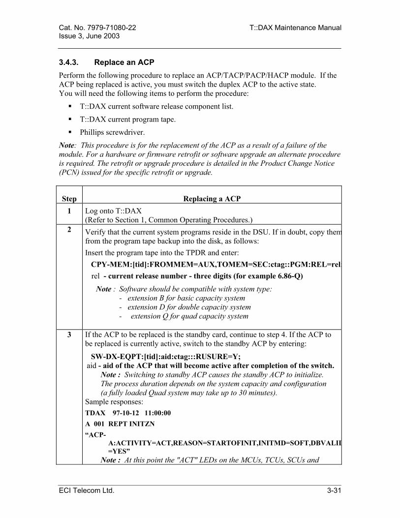
Cat. No. 7979-71080-22 T::DAX Maintenance Manual Issue 3, June 2003 3.4.3. Replace an ACP Perform the following procedure to replace an ACP/TACP/PACP/HACP module. If the ACP being replaced is active, you must switch the duplex ACP to the active state. You will need the following items to perform the procedure:
T::DAX current software release component list.
T::DAX current program tape.
Phillips screwdriver.
Note: This procedure is for the replacement of the ACP as a result of a failure of the module. For a hardware or firmware retrofit or software upgrade an alternate procedure is required. The retrofit or upgrade procedure is detailed in the Product Change Notice (PCN) issued for the specific retrofit or upgrade.
Step Replacing a ACP 1 Log onto T::DAX
(Refer to Section 1, Common Operating Procedures.) 2 Verify that the current system programs reside in the DSU. If in doubt, copy them
from the program tape backup into the disk, as follows: Insert the program tape into the TPDR and enter: CPY-MEM:[tid]:FROMMEM=AUX,TOMEM=SEC:ctag::PGM:REL=rel;
rel - current release number - three digits (for example 6.86-Q)
Note : Software should be compatible with system type: - extension B for basic capacity system - extension D for double capacity system
- extension Q for quad capacity system
3 If the ACP to be replaced is the standby card, continue to step 4. If the ACP to be replaced is currently active, switch to the standby ACP by entering:
SW-DX-EQPT:[tid]:aid:ctag:::RUSURE=Y; aid - aid of the ACP that will become active after completion of the switch.
Note : Switching to standby ACP causes the standby ACP to initialize. The process duration depends on the system capacity and configuration (a fully loaded Quad system may take up to 30 minutes).
Sample responses: TDAX 97-10-12 11:00:00 A 001 REPT INITZN “ACP-
A:ACTIVITY=ACT,REASON=STARTOFINIT,INITMD=SOFT,DBVALID=YES”
Note : At this point the "ACT" LEDs on the MCUs, TCUs, SCUs and
ECI Telecom Ltd. 3-31

T::DAX Maintenance Manual Cat. No. 7979-71080-22 Issue 3, June 2003
Step Replacing a ACP HSCUs will turn off. The T::DAX is now uploading the PCU software, starting with the SCU/HSCUs, followed by TCUs and MCUs as per shelf numbering. As each PCU is loaded, the "ACT" LED will come back on.
TDAX 97-10-12 11:05:00 A 002 REPT INITZN “ACP-A:ACTIVITY=ACT,REASON=ENDOFINIT,INITMD=SOFT,
DBVALID=YES” 4 Remove the standby ACP from service by entering:
RMV-EQPT:[tid]:aid:ctag; The “OOS” LED on removed ACP will go on.
5 Remove the Phillips screws securing the ACP to the ADMIN shelf. Pull the extractor handles to free the card from the connector. Plug out and remove the ACP.
6 Plug the new ACP into the ADMIN shelf and secure the Phillips screws. The “OOS” LED will remain on.
7 Restore service to the ACP by entering:
RST-EQPT:[tid]:aid:ctag; 8 Retrieve the stored programs within the active and the stand by ACP cards by
entering:
RTRV-MEMSTAT-EQPT::ACP-A&-B:ctag; Sample response: M B RTRV "ACP-A:MEMUSG=BOOT:DAT=99-05-19,RELEASE=6.81-X" "ACP-A:MEMUSG=PGM:DAT=01-08-06,RELEASE=7.07-D"
"ACP-B:MEMUSG=BOOT:DAT=99-05-19,RELEASE=6.81-X" "ACP-B:MEMUSG=PGM:DAT=01-08-06,RELEASE=7.07-D" "ACP-A:MEMUSG=DATA:DAT=02-01-07,TM=15-44-26" /*5 records retrieved*/ Compare the stand-by ACP boot and program with the active ACP: - Both ACP cards should have the same boot. If the stand-by ACP has
different boot, replace it with ACP card that has identical boot to the active ACP. For additional information, please contact customer support action line.
Both ACP should have the same program. If the stand-by ACP has differenprogram, continue to step 8, otherwise continue to step 11.
3-32 ECI Telecom Ltd.

Cat. No. 7979-71080-22 T::DAX Maintenance Manual Issue 3, June 2003
Step Replacing a ACP 9
Copy all programs from the DSU into the ACP, as follows:
Start local restoration mode to prevent any disturbances to the ACP, by entering:
STA-LOCL-RST:::ctag; Copy programs from disk (SEC) to ACP (WKG) by entering:
CPY-MEM:[tid]:FROMMEM=SEC,TOMEM=WKG:ctag::PGM:REL=rel;SEC - disk WKG - ACP PGM - instructs T::DAX to copy all programs rel - program release (i.e 7.07-B)
Note : There will be two momentary flashes of the "ACT" and "LOAD" LEDs on the standby ACP. The “LOAD” LED stays on for a while on the standby ACP. Then, the ACP will initialize. During the start of initialization, the "OOS" LEDs will light on both ACPs. The "OOS" light will then turn off on the previously active ACP and will remain lit on the standby ACP.
Sample responses: TDAX 97-10-12 11:00:00 A 001 REPT INITZN "ACP-A:ACTIVITY=ACT,REASON=STARTOFINIT,INITMD=SOFT,DBVALID=YES" Note : At this point the "ACT" LEDs on all PCUs will turn off. The T::DAX is now uploading the PCU software. As each PCU is loaded, the "ACT" LED will come back on. TDAX 97-10-12 11:05:00 A 002 REPT INITZN “ACP-A:ACTIVITY=ACT,REASON=ENDOFINIT,INITMD=SOFT,DBVALID=YES” Exit local restoration mode by entering: EXIT-LOCL-RST:::ctag;
10 Retrieve the stored programs within the ACP and AMU by entering:
RTRV-MEMSTAT-EQPT:[tid]:aid:ctag; aid - aid of AMU and currently active ACP (new ACP) Example: RTRV-MEMSTAT-EQPT::AMU&ACP-A:BRUN;
ECI Telecom Ltd. 3-33

T::DAX Maintenance Manual Cat. No. 7979-71080-22 Issue 3, June 2003
Step Replacing a ACP Sample response: TDAX 02-01-06 16:15:15 M BRUN RTRV "ACP-A:MEMUSG=BOOT:DAT=99-05-19,RELEASE=6.81-X" "ACP-A:MEMUSG=PGM:DAT=01-08-06,RELEASE=7.07-D" "ACP-A:MEMUSG=DATA:DAT=02-01-06,TM=16-15-14" "AMU:MEMUSG=TDAXPGM:DAT=01-08-06,RELEASE=7.07-D" "AMU:MEMUSG=ACPPGM:DAT=01-08-06,RELEASE=7.07-D" "AMU:MEMUSG=SCUPGM:DAT=99-02-09,RELEASE=6.80-D" "AMU:MEMUSG=TCUPGM:DAT=98-09-13,RELEASE=5.71-B" "AMU:MEMUSG=NMCUPGM:DAT=98-09-13,RELEASE=5.71-X" "AMU:MEMUSG=EMCUPGM:DAT=98-09-02,RELEASE=5.70-X" "AMU:MEMUSG=HMCUPGM:DAT=99-03-26,RELEASE=6.80-X" "AMU:MEMUSG=PMCUPGM:DAT=98-09-13,RELEASE=5.71-X" "AMU:MEMUSG=SMCUPGM:DAT=00-12-19,RELEASE=7.01-X" > < TDAX 02-01-06 16:15:15 M BRUN RTRV "AMU:MEMUSG=DMCUPGM:DAT=00-12-06,RELEASE=7.01-X" "AMU:MEMUSG=IMCUPGM:DAT=99-04-28,RELEASE=6.80-X" "AMU:MEMUSG=UMCUPGM:DAT=99-04-12,RELEASE=6.80-X" "AMU:MEMUSG=AMCUPGM:DAT=00-12-06,RELEASE=7.01-X" "AMU:MEMUSG=TMCUPGM:DAT=98-09-13,RELEASE=5.71-X" "AMU:MEMUSG=BMCUPGM:DAT=99-04-22,RELEASE=6.80-X" "AMU:MEMUSG=SPUPGM:DAT=01-01-15,RELEASE=7.01-X" "AMU:MEMUSG=OCUPGM:DAT=01-07-18,RELEASE=7.07-X" "AMU:MEMUSG=SMXPGM:DAT=01-07-18,RELEASE=7.07-X" "AMU:MEMUSG=MSMXPGM:DAT=01-07-18,RELEASE=7.07-X" "AMU:MEMUSG=HR3PGM:DAT=01-07-18,RELEASE=7.07-X" "AMU:MEMUSG=THR3PGM:DAT=01-07-18,RELEASE=7.07-X" > < TDAX 02-01-06 16:15:18 M BRUN RTRV "AMU:MEMUSG=NCUPGM:DAT=01-01-21,RELEASE=7.01-X" "AMU:MEMUSG=LRCUPGM:DAT=01-07-08,RELEASE=7.07-X" "AMU:MEMUSG=HRCUPGM:DAT=01-07-08,RELEASE=7.07-X" /*27 records retrieved*/
11 Compare the stored contents of the AMU and ACP with the T::DAX current software release component list, to verify successful update of the replaced unit. Verify that all items in the software release component list that reside on flash EPROMS in AMU (PCU PGM) and ACP (ACP PGM), exist and that date and version match exactly.
12 Log off T::DAX.
3-34 ECI Telecom Ltd.
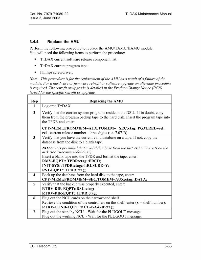
Cat. No. 7979-71080-22 T::DAX Maintenance Manual Issue 3, June 2003
3.4.4. Replace the AMU Perform the following procedure to replace the AMU/TAMU/HAMU module. You will need the following items to perform the procedure:
T::DAX current software release component list.
T::DAX current program tape.
Phillips screwdriver.
Note: This procedure is for the replacement of the AMU as a result of a failure of the module. For a hardware or firmware retrofit or software upgrade an alternate procedure is required. The retrofit or upgrade is detailed in the Product Change Notice (PCN) issued for the specific retrofit or upgrade.
Step Replacing the AMU 1 Log onto T::DAX.
2 Verify that the current system programs reside in the DSU. If in doubt, copy them from the program backup tape to the hard disk. Insert the program tape into the TPDR and enter:
CPY-MEM::FROMMEM=AUX,TOMEM= SEC:ctag::PGM:REL=rel; rel - current release number - three digits (i.e. 7.07-B)
3 Verify that you have the current valid database on a tape. If not, copy the database from the disk to a blank tape. NOTE: It is presumed that a valid database from the last 24 hours exists on the disk (see “Recommendations”). Insert a blank tape into the TPDR and format the tape, enter: RMV-EQPT:: TPDR:ctag::FRCD; INIT-SYS::TPDR:ctag::0:RUSURE=Y; RST-EQPT:: TPDR:ctag;
4 Back up the database from the hard disk to the tape, enter: CPY-MEM::FROMMEM=SEC,TOMEM=AUX:ctag::DATA;
5 Verify that the backup was properly executed, enter: RTRV-DIR-EQPT::DSU:ctag; RTRV-DIR-EQPT::TPDR:ctag;
6 Plug out the NCU cards on the narrowband shelf. Retrieve the condition of the controllers on the shelf, enter (x = shelf number): RTRV-COND-EQPT::NCU-x-A&-B:ctag;
7 Plug out the standby NCU – Wait for the PLUGOUT message. Plug out the working NCU - Wait for the PLUGOUT message.
ECI Telecom Ltd. 3-35

T::DAX Maintenance Manual Cat. No. 7979-71080-22 Issue 3, June 2003
Step Replacing the AMU 8 To replace the faulty AMU card, first remove the card from service by entering:
RMV-EQPT::AMU:ctag::FRCD; Remove the Phillips screws securing the AMU card to the shelf, pull the extractor handles and remove the AMU card. Connect the battery jumper on the new AMU card (pins 1 and 2 shorted - see T::DAX Installation Manual), insert the card in the slot on the shelf and secure the two Phillips screws.
9 Perform the diagnostics for the new AMU card, enter: DGN-EQPT::AMU:ctag; This process may take up to two minutes. The response should be: “RESULT=PASS“
10 Restore the AMU card back to service by entering: RST-EQPT::AMU:ctag; Initialize the AMU card by entering: INIT-SYS::AMU:ctag::0:RUSURE=Y;
11 To copy the program from the hard disk back to the ACP, first start local restoration mode to prevent any disturbances to the ACP by entering. STA-LOCL-RST:::ctag; Wait for a "COMPLD" response. Then copy the programs from hard disk (SEC) to the ACP (WKG) by entering: CPY-MEM::FROMMEM=SEC,TOMEM=WKG:ctag::PGM:REL=7.1x;
Note : When the programs are copied from the hard disk to the ACP, the AMU (PRI) automatically receives the software release specified in the CPY-MEM command.
There will be two momentary flashes of the “LOAD” and “ACT” LEDs on the standby ACP. The “LOAD” LED will then turn on for a while on the standby ACP. The ACP will then initialize. During the start of initialization, the “OOS” LEDs will light on both ACPs. The “OOS” LED will then turn off on the previously active ACP and will remain lit on the standby ACP. The "ACT" LEDs on the MCUs, TCUs, SCUs and HSCUs will then turn off while the T::DAX is uploading the PCU software. As each PCU is loaded, the "ACT" LED will return.
12 Wait for the ACP end of initialization message and then exit the local restoration mode by entering: EXIT-LOCL-RST:::ctag; Wait for a "COMPLD" response.
3-36 ECI Telecom Ltd.

Cat. No. 7979-71080-22 T::DAX Maintenance Manual Issue 3, June 2003
Step Replacing the AMU 13 Retrieve the stored programs within the AMU by entering:
RTRV-MEMSTAT-EQPT:[tid]:AMU:ctag; A sample response is: TDAX 02-01-07 15:44:37 M BRUN RTRV "AMU:MEMUSG=TDAXPGM:DAT=01-08-06,RELEASE=7.07-D" "AMU:MEMUSG=ACPPGM:DAT=01-08-06,RELEASE=7.07-D" "AMU:MEMUSG=SCUPGM:DAT=99-02-09,RELEASE=6.80-D" "AMU:MEMUSG=TCUPGM:DAT=98-09-13,RELEASE=5.71-B" "AMU:MEMUSG=NMCUPGM:DAT=98-09-13,RELEASE=5.71-X" "AMU:MEMUSG=EMCUPGM:DAT=98-09-02,RELEASE=5.70-X" "AMU:MEMUSG=HMCUPGM:DAT=99-03-26,RELEASE=6.80-X" "AMU:MEMUSG=PMCUPGM:DAT=98-09-13,RELEASE=5.71-X" "AMU:MEMUSG=SMCUPGM:DAT=00-12-19,RELEASE=7.01-X" "AMU:MEMUSG=DMCUPGM:DAT=00-12-06,RELEASE=7.01-X" "AMU:MEMUSG=IMCUPGM:DAT=99-04-28,RELEASE=6.80-X" "AMU:MEMUSG=UMCUPGM:DAT=99-04-12,RELEASE=6.80-X" > < TDAX 02-01-07 15:44:37 M BRUN RTRV "AMU:MEMUSG=AMCUPGM:DAT=00-12-06,RELEASE=7.01-X" "AMU:MEMUSG=TMCUPGM:DAT=98-09-13,RELEASE=5.71-X" "AMU:MEMUSG=BMCUPGM:DAT=99-04-22,RELEASE=6.80-X" "AMU:MEMUSG=SPUPGM:DAT=01-01-15,RELEASE=7.01-X" "AMU:MEMUSG=OCUPGM:DAT=01-07-18,RELEASE=7.07-X" "AMU:MEMUSG=SMXPGM:DAT=01-07-18,RELEASE=7.07-X" "AMU:MEMUSG=MSMXPGM:DAT=01-07-18,RELEASE=7.07-X" "AMU:MEMUSG=HR3PGM:DAT=01-07-18,RELEASE=7.07-X" "AMU:MEMUSG=THR3PGM:DAT=01-07-18,RELEASE=7.07-X" "AMU:MEMUSG=NCUPGM:DAT=01-01-21,RELEASE=7.01-X" "AMU:MEMUSG=LRCUPGM:DAT=01-07-08,RELEASE=7.07-X" "AMU:MEMUSG=HRCUPGM:DAT=01-07-08,RELEASE=7.07-X" > < TDAX 02-01-07 15:44:37 M BRUN RTRV /*24 records retrieved*/
To verify successful update of the replaced unit compare the stored contents of the AMU with the current software release component list. Verify that all items in the software release component list that reside on flash EPROMS in AMU (PCU PGM) exist in the AMU and that the date and version match exactly.
ECI Telecom Ltd. 3-37

T::DAX Maintenance Manual Cat. No. 7979-71080-22 Issue 3, June 2003
Step Replacing the AMU 14 To copy the database to the system, first initialize the AMU card:
INIT-SYS::AMU:ctag::0:RUSURE=Y; Insert the tape with the valid database into the TPDR. Copy the database from the tape or hard disk back to the new AMU. CPY-MEM::FROMMEM=AUX,TOMEM=PRI:Ctag::DATA; (from tape) CPY-MEM::FROMMEM=SEC,TOMEM=PRI:Ctag::DATA; (from hard disk) A “START OF INIT” message will be observed on the console: “ACP-B: ACTIVITY=ACT, REASON=STARTOFINIT, INITED=SOFT, DBVALID=YES” Wait for the "END OF INIT" message: “ACP-B:ACTIVITY=ACT,REASON=ENDOFINIT,INITED=SOFT,DBVALID=YES”
15 Verify no traffic loss. Verify correct initialization of all the PCUs.
16 Review the condition of the NCU cards in the narrowband shelf as recorded at the beginning of this procedure (step 6) by entering (x = shelf number): RTRV-COND-EQPT::NCU-x-A&-B:ctag; Plug in the working NCU card – Wait for the PLUGIN message. Plug in the standby NCU card – Wait for the PLUGIN message.
Important Note (especially for systems containing narrowband shelves): It is highly recommended to activate the automatic backup to the disk, by entering: SCHED-BKUP-MEM:[tid]:[aid]:ctag::[memusg],invl;
3-38 ECI Telecom Ltd.

Cat. No. 7979-71080-22 T::DAX Maintenance Manual Issue 3, June 2003
3.4.5. Replace the AIC Perform the following procedure to replace the AIC or TAIC modules. You will need a Phillips screwdriver to complete this procedure.
Step Replacing the AIC 1 Log onto T::DAX through a CPR port (DTM-A-1 to DTM-A-4). 2 Make sure that nobody is logged in from the CIT or from DTM-1. This can be
seen physically on the terminal connected to the CIT. It can also be verified by entering (through a CPR port):
RTRV-ACT-USER:[tid]:ALL:ctag; Sample response : TDAX 02-01-07 15:45:19 M B RTRV "TDAX:UPC=P15&M15&T15&N15&S15&C15,LINK=CIT" "TDAX:UPC=P15&M15&T15&N15&S15&C15,LINK=NTWRK-A-1-147.234.201.113" /*2 records retrieved*/
3 Make sure that all active PCUs in the system are PCU-A in all the shelves.
Make sure also that ACP-A is active.
Verification may be done by physically watching the “ACT” LEDs on the PCUs or by entering: RTRV-COND-EQPT:[tid]:aid:ctag; Sample response: M COND1 RTRV “TCU-1-A,EQPT: TYPEREP=IS&STBY” “TCU-1-B,EQPT:TYPEREP=IS&ACT” /*2 records retrieved*/If any active PCU is PCU-B, switch to PCU-A by entering:
SW-DX-EQPT:[tid]:aid:ctag:::RUSURE=Y; Example: SW-DX-EQPT::TCU-1-A:SW1; Sample response: A REPT SW “TCU-1-A,TCU-1-B” M SW1 COMPLD
ECI Telecom Ltd. 3-39

T::DAX Maintenance Manual Cat. No. 7979-71080-22 Issue 3, June 2003
Step Replacing the AIC 4 Remove the TAIC from service by entering:
RMV-EQPT:[tid]:AIC:ctag::FRCD; FRCD - forced. The (T)AIC must be forced from service since it is a single
unit (no protection). The "OOS" LED on removed TAIC unit will be on.
5 Remove the Phillips screws securing the (T)AIC to the ADMIN shelf. Pull the extractor handles to free the cards from the connector. Plug out and remove the unit to be replaced.
Note : On plugged out (T)AIC, all dry contact alarms will be canceled.
6 Plug the new (T)AIC into the ADMIN shelf. Secure the Phillips screws on the (T)AIC.
The "OOS" LED on removed (T)AIC will remain on and a real time clock alarm is generated.
7 Perform Switch ACP by entering: SW-DX-EQPT::ACP-B:ctag:::RUSURE=Y; The real time clock alarm will be cleared. After the ACP switch, ensure that the date and time displayed on the terminal is correct. If not, perform a date correction by using the ED-DAT command.
8 Restore service to the (T)AIC by entering:
RST-EQPT:[tid]:AIC:ctag; The "OOS" LED will turn off.
9 Log into the T::DAX from the CIT to make sure it works properly.
10 Check the system’s ability to switch PCUs by entering:
SW-DX-EQPT:[tid]:aid:ctag; Example: SW-DX-EQPT::TCU-1-B:SW2; Sample response : A REPT SW “TCU-1-B,TCU-1-A” M SW2 COMPLD
11 Log off T::DAX.
3-40 ECI Telecom Ltd.

Cat. No. 7979-71080-22 T::DAX Maintenance Manual Issue 3, June 2003 3.4.6. Replace the SIU/SPU/XPU Perform the following procedure to replace the SIU/SPU/XPU. You will need a Phillips screwdriver to complete this procedure. Note: When replacing SIU, SPU or XPU, system must be controlled from the CIT. Step Replacing the SIU/SPU/XPU
1 Log onto T::DAX, through the CIT, (not through the CPR connectors DTM-A-1 to DTM-A-4).
2 Make sure that nobody is logged in from any DTM. This is done by the following command: RTRV-ACT-USER:[tid]:ALL:ctag; Sample response: M USR2 RTRV “TDAX:P15&M15&T15&N15&S15&C15,LINK=CIT”
3 Remove the Phillips screws securing the CPR units to the Admin shelf. Pull the extractor handles to free the cards from the connector. Plug out and remove the unit to be replaced.
Note: It is not possible to remove and restore the SIU, SPU and XPU. Therefore, these units must be plugged out without removing. Thus, appropriate plug out alarms and equipment removal report messages will be issued, when the units are plugged out and alarm clear and equipment restoration messages will be issued when the units are plugged back in. Note: The XPU may be removed only after the SPU is plugged out. The SPU may be plugged out only after plugging the SIU.
4 Plug the new unit into the ADMIN shelf and plug back in all other CPR units previously pulled out (if any). Secure the Phillips screws of all units.
5 Log into the T::DAX from the CPR connectors (DTM-A-1 to DTM-A-4) to make sure it works properly.
6 To set the SPU TCP/IP parameters, follow the procedure below. Please refer to technical procedure TP 00-10-01 or the Enavis customer support for additional information.
7 Log off T::DAX.
ECI Telecom Ltd. 3-41

T::DAX Maintenance Manual Cat. No. 7979-71080-22 Issue 3, June 2003
Setting the SPU TCP/IP Use the following procedure to set the TCP/IP setting in the SPU.
Step Setting the SPU TCP/IP
1 Connect a terminal to DTM-A-1. (Recommended to use flat cable and null modem).
2 Press ABORT on the SPU card and then RESET and ABORT, if necessary, until the 147-BUG> prompt appears.
3 Entering and saving the TCP/IP parameters
Note: The TCP/IP Parameters must be introduced. If the real parameters are not known, introduce the parameters from the example presented below. When the real parameters will be known, use the present procedure in order to set them. In the example below, the following values are used:
The commands to be entered are: 147_Bug> MS FFFE0054 '23'00 (example of changing port number)
147_Bug> MS FFFE0064 '192.115.6.1'00 (example of changing gateway) 147_Bug> MS FFFE0074 '255.255.255.0'00 (example of changing subnet mask) 147_Bug> MS FFFE0084 '192.115.6.41'00 (example of changing ip address) Verify that the parameters were entered correctly. 147_Bug > MD FFFE0054:40 <CR> The parameters are: FFFE0054 – port number FFFE0064 – gateway address FFFE0074 – subnet mask FFFE0084 – IP address
TCP/IP Port Number 23 Default Gateway 192.115.6.1 Subnet Mask 255.255.255.0 T::DAX IP Address 192.115.6.41
3-42 ECI Telecom Ltd.

Cat. No. 7979-71080-22 T::DAX Maintenance Manual Issue 3, June 2003
Step Setting the SPU TCP/IP
4 Updating the Operating System Check that the system is defined as a “LYNX”: 147-Bug>MD FFFE0100 <ENTER> You should get the answer: FFFE0100 4C59 4E58 0000 0000 0000 0000 0000 0000 LYNX.. (Only the first 8 hex digits are important) Enter the following parameter (If necessary after 147-Bug>): MS FFFE0100 'LYNX'0 <ENTER> The string 'LYNX' must be in capital letter! Verify that you entered the parameter correctly: 147-Bug>MD FFFE0100 <ENTER> You should get the answer: FFFE0100 4C59 4E58 0000 0000 0000 0000 0000 0000 LYNX.… (Only the first 8 hex digits are important).
5 JMP Address Setting Note: If the parameter is set to the correct value, it is enough to press ENTER. Type (After 147_Bug>): M FFFE00D4 <Enter> The answer will be: FFFE00D4 xxxx?
Type: 0000 <Enter> The answer will be: FFFE00D6 xxxx?
Type: D000 <Enter> The answer will be: FFFE00D8 0000? Type: . <Enter> (dot and ENTER) You will get the prompt again.
ECI Telecom Ltd. 3-43

T::DAX Maintenance Manual Cat. No. 7979-71080-22 Issue 3, June 2003
Step Setting the SPU TCP/IP
6 Soft Reset A. Type (after 147-Bug>); RB <ENTER> You will get new line: Boot at Power-up only or any board Reset [P,R] = R? B. Press ENTER. You will get new line: Enable search of VMEbus [Y,N] = Y? C. Press ENTER. You will get new line: Boot direct address = $FFA00000? or: Boot direct address = $FFBFF000? In case of getting FFA00000, type: FFBFF000 <ENTER> In case of getting FFBFF000, press ENTER. You will get a new line: ROM boot enabled And another line with the prompt (147-Bug>)
7 SPU Initialization
Press the RESET button on the SPU card and wait approx 7-10 minutes, (At this time you will see numbers running on the screen) until you receive LOGIN screen. Verify that the SPU has the correct software version: RTRV-MEMSTAT-EQPT::SPU-A:L; Verify the answer match the information in the AMU. If the answer does not match the information in the AMU, Press the reset button on the SPU. Wait for CPR initialization to be completed and verify that now the SPU has the correct software version. If the answer still doesn’t match the information in the AMU, call Enavis support center.
3-44 ECI Telecom Ltd.

Cat. No. 7979-71080-22 T::DAX Maintenance Manual Issue 3, June 2003
3.4.7. Replace the TSIU/SXPU Perform the following procedure to replace the TSIU/SXPU. You will need a Phillips screwdriver to complete this procedure. Note: When replacing TSIU or SXPU the system must be controlled from the CIT.
Step Replacing the TSIU/SXPU
1 Perform a
2 Log onto T::DAX, through the CIT (not through the CPR connectors DTM-A-1 to DTM-A-4).
3 Make sure that nobody is logged in from any DTM. This is done by the following command: RTRV-ACT-USER:[tid]:ALL:ctag; Sample response: M USR2 RTRV “TDAX:P15&M15&T15&N15&S15&C15,LINK=CIT”
4 Remove the Phillips screws securing the CPR units to the Admin shelf. Pull the extractor handles to free the cards from the connector. Plug out and remove the unit to be replaced.
Note: It is not possible to remove and restore the TSIU or SXPU, these units must be plugged out without removing. Appropriate plug out alarms and equipment removal report messages will be issued, when the units are plugged out and alarm clear and equipment restoration messages will be issued when the units are plugged back in. Note: The SXPU may be removed only after the TSIU is plugged out.
5 Plug the new unit into the ADMIN shelf and plug back in all other CPR units previously pulled out (if any). Secure the Phillips screws of all units.
6 Verify the correct version of the SXPU: RTRV-MEMSTAT-EQPT::AMU:RM; The line with the SPU version is also for the SXPU. Verify the current version of the SXPU: RTRV-MEMSTAT-EQPT::SPU-A:RS; If the SXPU current version matches the one in the AMU proceed to part 7.
ECI Telecom Ltd. 3-45

T::DAX Maintenance Manual Cat. No. 7979-71080-22 Issue 3, June 2003
Step Replacing the TSIU/SXPU
6 Please refer to the Enavis customer support as to the instruction for loading the SXPU software. The procedure is described in technical procedure TP 00-10-01. The SXPU software tape with the relevant software version is needed.
7 SXPU Nvram parameter setting (IP address): Connect a PC with terminal emulator to the DTM-A-1 port. Press RESET, wait for 5 seconds and press ABORT on SXPU until receiving PPC1-Bug>. Close the terminal emulator and run the Nvram parameter setting utility. (In windows press START, Programs, CPR_conf and cpr_nv) Select the correct COM port number (In the upper left corner) that the DTM-A-1 is connected to. Press on the READ NVRAM Button. Wait for about 5 Min. until buttons are active. Change the values TCPIP / X25 as required in the table. Please note that changing the IP address effects the subnet mask, for using special subnet masks change it after the IP! Press on the UPDATE NVRAM button. Wait for about 5 Min. until buttons are active again. Press on EXIT button. It will take few seconds for the program to close.
8 Log into the T::DAX from the CPR connectors (DTM-A-1 to DTM-A-4) to make sure it works properly.
Note: It may take up to 10 minutes for the CPR to restore service.
9 Log off T::DAX.
3-46 ECI Telecom Ltd.
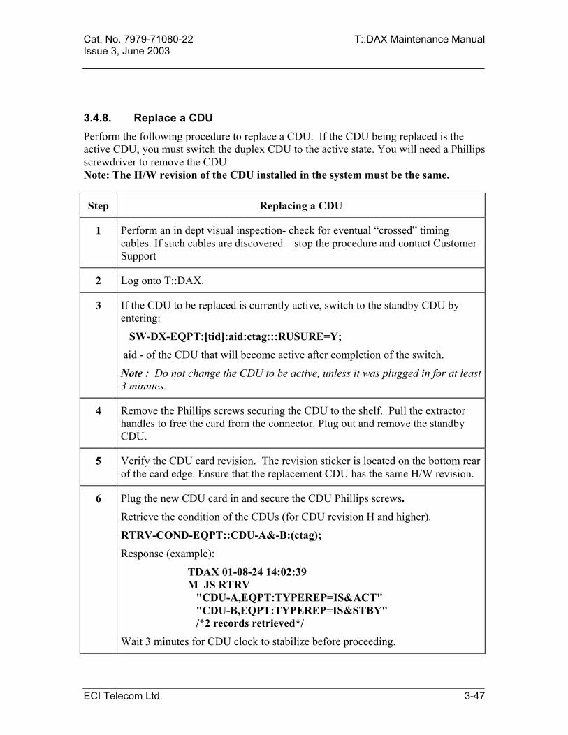
Cat. No. 7979-71080-22 T::DAX Maintenance Manual Issue 3, June 2003
3.4.8. Replace a CDU Perform the following procedure to replace a CDU. If the CDU being replaced is the active CDU, you must switch the duplex CDU to the active state. You will need a Phillips screwdriver to remove the CDU. Note: The H/W revision of the CDU installed in the system must be the same.
Step Replacing a CDU
1 Perform an in dept visual inspection- check for eventual “crossed” timing cables. If such cables are discovered – stop the procedure and contact Customer Support
2 Log onto T::DAX.
3 If the CDU to be replaced is currently active, switch to the standby CDU by entering:
SW-DX-EQPT:[tid]:aid:ctag:::RUSURE=Y; aid - of the CDU that will become active after completion of the switch.
Note : Do not change the CDU to be active, unless it was plugged in for at least 3 minutes.
4 Remove the Phillips screws securing the CDU to the shelf. Pull the extractor handles to free the card from the connector. Plug out and remove the standby CDU.
5 Verify the CDU card revision. The revision sticker is located on the bottom rear of the card edge. Ensure that the replacement CDU has the same H/W revision.
6 Plug the new CDU card in and secure the CDU Phillips screws.
Retrieve the condition of the CDUs (for CDU revision H and higher).
RTRV-COND-EQPT::CDU-A&-B:(ctag);
Response (example):
TDAX 01-08-24 14:02:39 M JS RTRV "CDU-A,EQPT:TYPEREP=IS&ACT" "CDU-B,EQPT:TYPEREP=IS&STBY" /*2 records retrieved*/
Wait 3 minutes for CDU clock to stabilize before proceeding.
ECI Telecom Ltd. 3-47

T::DAX Maintenance Manual Cat. No. 7979-71080-22 Issue 3, June 2003
Step Replacing a CDU
7 Switch to standby CDU.
SW-DX-EQPT::CDU-n:(ctag):::RUSURE=Y Response example:
TDAX4 01-08-24 14:07:08
A 064 REPT SW
"CDU-B,CDU-A:"
TDAX04 01-08-24 14:07:12
M JS COMPLD Note: If you don’t receive the correct response from a command contact the Customer Support action line.
8 Log off T::DAX.
3-48 ECI Telecom Ltd.

Cat. No. 7979-71080-22 T::DAX Maintenance Manual Issue 3, June 2003
3.4.9. Replace the DSU Perform the following procedure to replace the DSU. You will need the following items to perform this procedure:
T::DAX current program tape.
Phillips screwdriver.
Note: When replacing a DSU, all information within the DSU is lost. It includes the historical PM, LOG file, maps, scheduled PM, delayed activation commands, programs and database.
Step Replacing the DSU
1 Log onto the T::DAX. 2 If necessary, make a backup copy of all required items residing on disk by
using the following procedure: A. Insert a blank tape into the TPDR. B. Remove the TPDR form service. Enter: RMV-EQPT:[tid]:TPDR:ctag::FRCD;
(The DSU must be forced from service since it is a single unit without protection).
C. Initialize the tape: INIT-SYS:[tid]:TPDR:ctag::0:RUSURE=Y; D. Restore the TPDR: RST-EQPT:[tid]:TPDR:ctag; E. Make a backup. Enter: CPY-MEM:[tid]:FROMMEM=SEC,TOMEM=AUX:ctag::memusg; memusg - PGM, DATA, LOG, PM or MAP Repeat the procedure in step 2 for copying the different memory files (program, data, log files, PM and maps)
3 Remove the DSU from service. Enter: RMV-EQPT:[tid]:DSU:ctag::FRCD; (The DSU must be forced from service since it is a single unit without protection).
ECI Telecom Ltd. 3-49
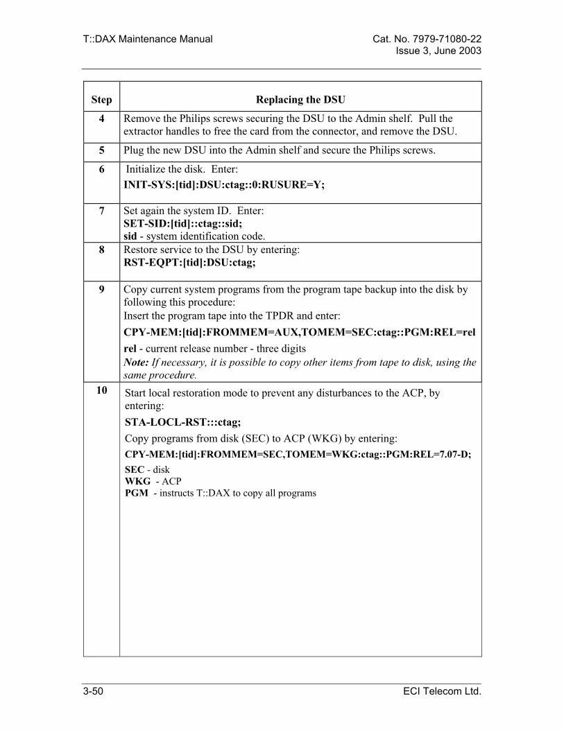
T::DAX Maintenance Manual Cat. No. 7979-71080-22 Issue 3, June 2003
Step Replacing the DSU
4 Remove the Philips screws securing the DSU to the Admin shelf. Pull the extractor handles to free the card from the connector, and remove the DSU.
5 Plug the new DSU into the Admin shelf and secure the Philips screws.
6 Initialize the disk. Enter: INIT-SYS:[tid]:DSU:ctag::0:RUSURE=Y;
7 Set again the system ID. Enter: SET-SID:[tid]::ctag::sid; sid - system identification code.
8 Restore service to the DSU by entering: RST-EQPT:[tid]:DSU:ctag;
9 Copy current system programs from the program tape backup into the disk by following this procedure: Insert the program tape into the TPDR and enter: CPY-MEM:[tid]:FROMMEM=AUX,TOMEM=SEC:ctag::PGM:REL=relrel - current release number - three digits Note: If necessary, it is possible to copy other items from tape to disk, using the same procedure.
10 Start local restoration mode to prevent any disturbances to the ACP, by entering: STA-LOCL-RST:::ctag; Copy programs from disk (SEC) to ACP (WKG) by entering: CPY-MEM:[tid]:FROMMEM=SEC,TOMEM=WKG:ctag::PGM:REL=7.07-D; SEC - disk WKG - ACP PGM - instructs T::DAX to copy all programs
3-50 ECI Telecom Ltd.
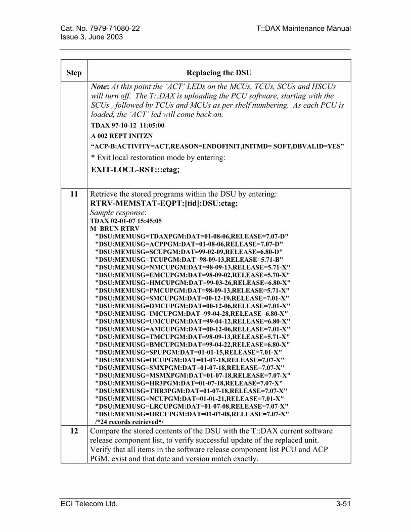
Cat. No. 7979-71080-22 T::DAX Maintenance Manual Issue 3, June 2003
Step Replacing the DSU
Note: At this point the ‘ACT’ LEDs on the MCUs, TCUs, SCUs and HSCUs will turn off. The T::DAX is uploading the PCU software, starting with the SCUs , followed by TCUs and MCUs as per shelf numbering. As each PCU is loaded, the ‘ACT’ led will come back on. TDAX 97-10-12 11:05:00 A 002 REPT INITZN “ACP-B:ACTIVITY=ACT,REASON=ENDOFINIT,INITMD= SOFT,DBVALID=YES”
* Exit local restoration mode by entering: EXIT-LOCL-RST:::ctag;
11 Retrieve the stored programs within the DSU by entering: RTRV-MEMSTAT-EQPT:[tid]:DSU:ctag; Sample response: TDAX 02-01-07 15:45:05 M BRUN RTRV "DSU:MEMUSG=TDAXPGM:DAT=01-08-06,RELEASE=7.07-D" "DSU:MEMUSG=ACPPGM:DAT=01-08-06,RELEASE=7.07-D" "DSU:MEMUSG=SCUPGM:DAT=99-02-09,RELEASE=6.80-D" "DSU:MEMUSG=TCUPGM:DAT=98-09-13,RELEASE=5.71-B" "DSU:MEMUSG=NMCUPGM:DAT=98-09-13,RELEASE=5.71-X" "DSU:MEMUSG=EMCUPGM:DAT=98-09-02,RELEASE=5.70-X" "DSU:MEMUSG=HMCUPGM:DAT=99-03-26,RELEASE=6.80-X" "DSU:MEMUSG=PMCUPGM:DAT=98-09-13,RELEASE=5.71-X" "DSU:MEMUSG=SMCUPGM:DAT=00-12-19,RELEASE=7.01-X" "DSU:MEMUSG=DMCUPGM:DAT=00-12-06,RELEASE=7.01-X" "DSU:MEMUSG=IMCUPGM:DAT=99-04-28,RELEASE=6.80-X" "DSU:MEMUSG=UMCUPGM:DAT=99-04-12,RELEASE=6.80-X" "DSU:MEMUSG=AMCUPGM:DAT=00-12-06,RELEASE=7.01-X" "DSU:MEMUSG=TMCUPGM:DAT=98-09-13,RELEASE=5.71-X" "DSU:MEMUSG=BMCUPGM:DAT=99-04-22,RELEASE=6.80-X" "DSU:MEMUSG=SPUPGM:DAT=01-01-15,RELEASE=7.01-X" "DSU:MEMUSG=OCUPGM:DAT=01-07-18,RELEASE=7.07-X" "DSU:MEMUSG=SMXPGM:DAT=01-07-18,RELEASE=7.07-X" "DSU:MEMUSG=MSMXPGM:DAT=01-07-18,RELEASE=7.07-X" "DSU:MEMUSG=HR3PGM:DAT=01-07-18,RELEASE=7.07-X" "DSU:MEMUSG=THR3PGM:DAT=01-07-18,RELEASE=7.07-X" "DSU:MEMUSG=NCUPGM:DAT=01-01-21,RELEASE=7.01-X" "DSU:MEMUSG=LRCUPGM:DAT=01-07-08,RELEASE=7.07-X" "DSU:MEMUSG=HRCUPGM:DAT=01-07-08,RELEASE=7.07-X" /*24 records retrieved*/
12 Compare the stored contents of the DSU with the T::DAX current software release component list, to verify successful update of the replaced unit. Verify that all items in the software release component list PCU and ACP PGM, exist and that date and version match exactly.
ECI Telecom Ltd. 3-51
T::DAX Maintenance Manual Cat. No. 7979-71080-22 Issue 3, June 2003
3.4.10. Replace a Test Access Unit (TAU) Use the following procedure to replace a Test Access Unit. You need a 3 mm Allen wrench to perform this procedure. Note: Test Access Unit is installed only in basic and double configuration systems. Warning: If any of the ports 1-A-1 to 1-A-14 are used for service through the TACC unit, they must first be rerouted before the TACC unit can be replaced.
Step Replacing a Test Access Unit
1 Remove any connections made at the front of the Test Access Unit.
2 Remove the two Allen screws securing the Test Access Unit to the Admin shelf.
3 Remove the Test Access Unit.
4 Replace the Test Access Unit and secure with the Allen screws.
5 Replace the connections made at the front of the Test Access Unit.
3-52 ECI Telecom Ltd.

Cat. No. 7979-71080-22 T::DAX Maintenance Manual Issue 3, June 2003
3.4.11. Replace the TPDR Perform the following procedure to replace the tape drive (TPDR). You will need a Phillips screwdriver to complete this procedure.
Step Replacing the TPDR
1 Log onto T::DAX.
2 If the TPDR is in service, place it in a maintenance state by entering:
RMV-EQPT:[tid]:TPDR:ctag::FRCD; The TPDR must be forced out of service since it is a single unit.
3 Remove the power ribbon and the SCSI bus ribbon from the back of the TPDR.
4 Remove the Phillips screws from the back of the TPDR securing it to the Admin shelf and remove the unit.
5 Replace the TPDR, secure with the Phillips screws and reconnect the power and SCSI bus ribbon cables.
6 Perform diagnostics on the TPDR by entering:
DGN-EQPT:[tid]:TPDR:ctag;
7 Restore service to the TPDR by entering:
RST-EQPT:[tid]:TPDR:ctag;
8 If desired a formatted tape should be inserted in the tape drive and the database copied to the tape to verify operation. A formatted tape is one that has been initialized by the system. If this is required, refer to section 3.4.8, Initialize a Tape in the TPDR.
To copy the database to the TPDR enter:
CPY-MEM::FROMMEM=SEC, TOMEM=AUX: ctag::DATA; To verify that the program has been copied enter:
RTRV-DIR-EQPT::TPDR:ctag; The response will indicate a database file with the current data of time.
9 Log off T::DAX.
ECI Telecom Ltd. 3-53

T::DAX Maintenance Manual Cat. No. 7979-71080-22 Issue 3, June 2003
3.4.12. Replace the MODR Perform the following procedure to replace the Magneto Optical Drive (MODR). You will need a Phillips screwdriver to complete this procedure.
Step Replacing the MODR
1 Log onto T::DAX.
2 If the MODR is in service, place it in a maintenance state by entering:
RMV-EQPT:[tid]:MODR:ctag::FRCD; The MODR must be forced out of service since it is a single unit.
3 Remove the power ribbon and the SCSI bus ribbon from the back of the MODR.
4 Extract the MODR unit from the shelf.
5 Replace the MODR, secure with the Phillips screws and reconnect the power and SCSI bus ribbon cables.
6 Perform diagnostics on the MODR by entering:
DGN-EQPT:[tid]:MODR:ctag;
7 Restore service to the MODR by entering:
RST-EQPT:[tid]:MODR:ctag;
8 If desired, a formatted magnetic disk should be inserted in the drive and the database copied to the disk to verify operation.
To copy the database to the MODR enter:
CPY-MEM::FROMMEM=SEC, TOMEM=AUX: ctag::DATA;
To verify that the program has been copied enter:
RTRV-DIR-EQPT::MODR:ctag; The response will indicate a database file with the current data of time.
9 Log off T::DAX.
3-54 ECI Telecom Ltd.

Cat. No. 7979-71080-22 T::DAX Maintenance Manual Issue 3, June 2003
3.4.13. Replace an ACC module The ACC modules are defined as part of the PCU bus. In order to safely switch an ACC module the entire PCU bus that the module supports (A or B) must not be the active unit. Perform the following procedures to replace an ACC module on the COMM shelf. You will need a Phillips screwdriver to complete this procedure.
Step Replacing an ACC
1 Log onto T::DAX.
2 If the ACC to be replaced is currently active, switch the associated PCU bus (A or B respectively) to standby by entering:
SW-DX-EQPT:[tid]:PCUBUS-A (or B) :ctag:::RUSURE=Y;
3 Ensure that the PCU bus is not in service, by entering:
RTRV-COND-EQPT:[tid]: PCUBUS-A (or B) :ctag;
4 Remove the Phillips screws securing the ACC to the shelf, pull the extractor handles to free the card from the connector, and extract the unit.
5 Insert a replacement ACC in the slot and secure it in place by closing the handle extractors and replacing and securing the Phillips screws.
Note: It may take up to 2 minutes for the ACC module to become “In Service” after plugin.
6 Check the condition of the ACC module, by entering:
RTRV-MEMSTAT-EQPT:[tid]: ACC :ctag;
7 Log off T::DAX.
ECI Telecom Ltd. 3-55
T::DAX Maintenance Manual Cat. No. 7979-71080-22 Issue 3, June 2003
3.4.14. Replace the ABU module The ABU module distributes the AB selection line to all the control units in all the shelves. When the ABU is removed from service the PCUs on all the shelves will switch to unit A (if not already active). This will cause an alarm on the system and may cause service interruption. In order to avoid any problem, all the PCUs on all the shelves (interface and switching network shelves) should be first switched to module A before the ABU is removed. Perform the following procedures to replace the ABU module on the COMM shelf. You will need a Phillips screwdriver to complete this procedure.
Step Replacing an ABU
1 Log onto T::DAX.
2 Check that PCU module A (xCU-A) on all the shelves is the active module. If a shelf has PCU-B as the active module, switch to PCU-A by entering:
SW-DX-EQPT:[tid]:aid:ctag:::RUSURE=Y; aid – aid of the PCU module A unit.
5 Check that PCU module A (xCU-A) on all the shelves is not in service by entering:
RTRV-COND-EQPT:[tid]:aid:ctag; aid – aid of the PCU module A unit
3 Remove the Phillips screws securing the ABU to the shelf, pull the extractor handles to free the card from the connector, and extract the unit.
4 Insert a replacement ABU in the slot and secure it in place by closing the handle extractors and replacing and securing the Phillips screws.
6 Log off T::DAX.
3-56 ECI Telecom Ltd.

Cat. No. 7979-71080-22 T::DAX Maintenance Manual Issue 3, June 2003
3.4.15.
Replace a TDC module The TDC module distributes the clock synchronization from the CDU on the Admin shelf to all the shelves requiring it. TDC-A distributes the clock signals from CDU-A, and TDC-B distributes the clock signals from CDU-B. In order to avoid any problem when replacing a TDC module the associated CDU should be first switched to protection before the TDC is removed. Perform the following procedures to replace a TDC module on the TDU shelf. You will need a Phillips screwdriver to complete this procedure.
Step Replacing a TDC
1 Log onto T::DAX.
2 Check the status of the CDU modules to see if the associated CDU module (A or B) to the TDC to be replaces is active or standby by entering: (note: This command can be used for CDU revision H and above):
RTRV-COND-EQPT:[tid]:CDU-A (or B) :ctag;
3 If the CDU module (A or B) associated to the TDC to be replaces is active, switch it to standby by entering:
SW-DX-EQPT:[tid]:CDU-A (or B) :ctag:::RUSURE=Y;
4 Remove the Phillips screws securing the TDC to the shelf, pull the extractor handles to free the card from the connector, and extract the unit.
5 Insert a replacement TDC in the slot and secure it in place by closing the handle extractors and replacing and securing the Phillips screws.
6 Log off T::DAX.
ECI Telecom Ltd. 3-57

T::DAX Maintenance Manual Cat. No. 7979-71080-22 Issue 3, June 2003
3.4.16. Replace an SCU/HSCU Perform the following procedures to replace an SCU/HSCU. You will need a 5 mm Allen wrench to perform this procedure. Note: This procedure is for the replacement of the SCU/ HSCU as a result of a failure of the module. For a hardware or firmware retrofit or software upgrade an alternate procedure is required. The retrofit or upgrade procedure is detailed in the Product Change Notice (PCN) issued for the specific retrofit or upgrade.
Step Replacing an SCU/ HSCU
1 Log onto T::DAX.
2 If the SCU/ HSCU to be replaced is currently active, switch to the currently standby unit by entering:
SW-DX-EQPT:[tid]:aid:ctag:::RUSURE=Y; aid –of the unit that will become active after completion of the switch.
3 If the SCU/ HSCU is in service, place it in the maintenance state by entering:
RMV-EQPT:[tid]:aid:ctag:::RUSURE=Y;
The "OOS" LED will turn on.
4 Remove the two Allen screws securing the SCU/ HSCU to the Switching Network shelf and remove the SCU.
5 Slide the replacement SCU/ HSCU into place on the shelf until it engages with the connector and secure with the Allen screws.
6
Perform diagnostics on the SCU/ HSCU by entering:
DGN-EQPT:[tid]:aid:ctag; The "OOS" LED will go out momentarily during this process.
7 Restore service to the SCU/ HSCU by entering:
RST-EQPT:[tid]:aid:ctag;
The "OOS" LED will turn off.
8 Log off T::DAX.
3-58 ECI Telecom Ltd.

Cat. No. 7979-71080-22 T::DAX Maintenance Manual Issue 3, June 2003
3.4.17. Replace an ISU Perform the following procedure to replace an ISU / HISU module. You will need a 5 mm Allen wrench to perform this procedure. Step Replacing an ISU
1 Log onto T::DAX.
2 An ISU alarm may be caused by a defective ISU or OCNT connector. In order to diagnose the cause of the problem, enter the following command: DGN-EQPT:[tid]:ISU-n:ctag;
3 If the protection ISU is to be replaced (ISU-18 in a basic or double configuration, or ISU-32 in a quad or octal configuration) verify that it is not active by entering: RTRV-COND-EQPT:[tid]:aid:ctag;
4 If the ISU is in service, place it in the maintenance state by entering: RMV-EQPT:[tid]:aid:ctag; The "OOS" LED(s) will turn on. Note: Placing an active ISU in the maintenance state causes T::DAX to automatically switch to the protection ISU. Note: When the T::DAX is a double, quad or octal configuration (2, 4, or 8 Switching Network shelves), both the (H)ISU-L and (H)ISU-R will be placed in maintenance state with one command, since they are both defined by one AID. The specific (H)ISU- L or (H)ISU-R can then be replaced and both are restored to service with one command
5 Remove the two Allen screws securing the ISU and remove it from the shelf. In a double, quad or octal configuration the ISU connector (ICNT) must first be removed (and the OCNT connector in an octal configuration) and then the specific ISU, (H)ISU-L or (H)ISU-R, can be removed and replaced.
6 Slide the replacement module into place until it engages with the connector and secure with the Allen screws. In a double, quad or octal configuration, replace the ICNT connector between the two ISUs. In an octal configuration replace the OCNT connector between the HISUs of the two lineups.
7 Perform diagnostics on the ISU by entering: DGN-EQPT:[tid]:aid:ctag; This process may take a few minutes depending on the system configuration. The "OOS" LED will stay on during the diagnostics.
8 Restore service to the ISU by entering: RST-EQPT:[tid]:aid:ctag; This process may take a few minutes depending on the system configuration.
9 Log off T::DAX.
ECI Telecom Ltd. 3-59

T::DAX Maintenance Manual Cat. No. 7979-71080-22 Issue 3, June 2003
3.4.18. Replace a TSU Perform the following procedures to replace a TSU. You will need a 5 mm Allen wrench to perform this procedure.
Step Replacing a TSU 1 Log onto T::DAX. 2 Note: Placing an active TSU in the maintenance state causes T::DAX to
automatically switch the active TSU to the Protection TSU. Note: When the T::DAX system is a quad or octal configuration, TSU B and TSU T will both be placed in maintenance state with one command. The specific TSU (TSU B or TSU T) is replaced and then TSU B and TSU T are both restored to service with one command.
If the TSU to be replaced is PTSU, verify that it is not active by entering: RTRV-COND-EQPT:[tid]:aid:ctag; aid – aid of the protection unit; TSU-1-9 or TSU-2-9.
3 If the TSU is in service, place it in the maintenance state by entering: RMV-EQPT:[tid]:aid:ctag; The "OOS" LED on the TSU will turn on and the "TSU OOS" indication on the active SCU/ HSCU (on the front panel) will also turn on.
4 Remove the cover from the rear of the Switching Network shelf. 5 Remove the two Allen screws from the cable-retaining bar directly in front of
the TSUs and remove the bar. 6 Remove the Allen screw from the TSU cable connector and disconnect the
connector. 7 Remove the two Allen screws securing the TSU and remove the TSU from the
shelf. In a quad configuration the TSU connector (TCNT) must first be removed and then the specific TSU, TSU B or TSU T, can be removed and replaced.
8 Slide the replacement TSU into place on the shelf until it engages with the connector and secure with the Allen screws. In a quad configuration, replace the TCNT, connecting the TSU B and TSU T together.
9 Caution: Use extreme care when inserting the cable connectors onto the pins. If the connector is not lined up properly, the pins could bend.
Connect the TSU cable and secure with the Allen screw. 10 Perform diagnostics on the TSU by entering:
DGN-EQPT:[tid]:aid:ctag; This process may take a few minutes depending on the system configuration.
11 Restore service to the TSU by entering: RST-EQPT:[tid]:aid:ctag; The "OOS" LEDs on the TSU and active SCU/ HSCU will turn off.
12 Log off T::DAX, replace the cable-retaining bar and shelf cover.
3-60 ECI Telecom Ltd.

Cat. No. 7979-71080-22 T::DAX Maintenance Manual Issue 3, June 2003
3.4.19. Replace a TSU Cable Perform the following procedure to replace a TSU or PTSU cable.
Step Replacing a TSU Cable
1 Log onto T::DAX.
2 If the TSU to which the faulty cable is connected is PTSU, verify that it is not active by entering:
RTRV-COND-EQPT:[tid]:aid:ctag;
aid - of the protection unit.
3 If the TSU, to which the faulty cable is connected, is in service, place it in a maintenance state by entering:
RMV-EQPT:[tid]:aid:ctag;
4 Remove the faulty cable from the TSU and Interface shelf by removing the two Allen screws from the cable-retaining bar directly in front of the TSUs and remove the bar.
5 Remove the Allen screw from the TSU cable connector and disconnect the connector.
6 Repeat steps 4 and 5 to disconnect the cable from the interface shelf. For type II interface shelf, the cable should be disconnected from both, “odd and even” shelves.
7 Caution: Use extreme care when inserting the cable connectors onto the pins. If the connector is not lined up properly, the pins could bend.
Connect the TSU cable and secure with the Allen screw.
8 Restore service to the TSU by entering:
RST-EQPT:[tid]:aid:ctag;
9 Log off T::DAX.
ECI Telecom Ltd. 3-61

T::DAX Maintenance Manual Cat. No. 7979-71080-22 Issue 3, June 2003
3.4.20. Replace a TCU Perform the following procedure to replace a TCU. You will need the following tools for this procedure:
3 mm Allen wrench
Step Replacing a TCU
1 Log onto T::DAX.
2 Remove the cover from the DS1/E1 Interface Shelf.
3 If the TCU to be replaced is currently active, switch to the currently standby unit by entering:
SW-DX-EQPT:[tid]:aid:ctag:::RUSURE=Y;
aid – of the unit that will become active after completion of the switch.
4 Remove the TCU from service by entering:
RMV-EQPT:[tid]:aid:ctag; The "OOS" LED will turn on.
5 Grasp the TCU by both handle extractors and pull the TCU from the shelf.
6 Insert a replacement TCU in the slot and secure it in place by closing the handle extractors.
7 Perform diagnostics on the TCU by entering:
DGN-EQPT:[tid]:aid:ctag;
The "OOS" LED will go out during the diagnostics.
8 Restore service to the TCU by entering:
RST-EQPT:[tid]:aid:ctag; The OOS LED will turn off.
The time period required for this process to complete depends on the number of ports and cross connects in the shelf.
9 Log off T::DAX.
10 Replace the shelf cover.
3-62 ECI Telecom Ltd.
Cat. No. 7979-71080-22 T::DAX Maintenance Manual Issue 3, June 2003
3.4.21. Replace a DS1 or E1 Interface Card Perform the following procedure to replace a DS1 or E1 Interface card. Warning: The DS1/E1 interface cards are not backed-up. Replacement of the cards in traffic will cause loss of service.
Step Replacing a DS1 or E1 Interface Card
1 Log onto T::DAX.
2 Remove the cover from the DS1/E1 Interface Shelf containing the DS1 or E1 Interface card to be removed. Identify the proper port card to be removed.
Note: The LED on the DS1/E1 card will only be on if the card is failed or if it is removed by command.
3 Remove the DS1/E1 Interface card from service by entering:
RMV-EQPT:[tid]:aid:ctag::[mode]:[INCL=incl]; mode – specifies how the unit is removed from service as follows: NORM - (default) the unit is removed from service only if the removal does not interrupt service; service-interrupting removal will be denied. FRCD - the unit is removed from service regardless of effect.
incl – enter Y to remove even if the port is part of a red-lined connection (subject to mode) or N (default) to remove only if the port is not part of a red-lined connection (subject to mode). If the card's LED was not previously on, it will turn on with this command.
4 Grasp the card by the handle and remove it from the shelf.
5 Insert a new DS1 or E1 Interface card in the slot and secure it in place.
6 Perform diagnostics on the DS1 or E1 Interface card by entering:
DGN-EQPT:[tid]:aid:ctag;
7 Restore service to the DS1 Interface card by entering:
RST-EQPT:[tid]:aid:ctag; The "OOS" LED on the card will turn off.
8 Log off T::DAX.
9 Replace the shelf cover.
ECI Telecom Ltd. 3-63

T::DAX Maintenance Manual Cat. No. 7979-71080-22 Issue 3, June 2003
3.4.22. Replace an MCU Perform the following procedures to replace an MCU.
Step Replacing an MCU 1 Log onto T::DAX.
2 Remove the cover from the interface shelf.
3 If the MCU to be replaced is currently active, switch to the currently standby unit by entering: SW-DX-EQPT:[tid]:aid:ctag:::RUSURE=Y; aid – aid of the unit that will become active after completion of the switch.
4 Remove the MCU from service by entering: RMV-EQPT:[tid]:aid:ctag;
The "OOS" LED will turn on.
5 Grasp the MCU by the handle extractors and pull the MCU from the shelf.
6 Insert a replacement MCU in the slot and secure it in place by closing the handle extractors.
7 Perform diagnostics on the MCU by entering: DGN-EQPT:[tid]:aid:ctag; The "OOS" LED will momentarily turn on.
8 Restore service to the MCU by entering: RST-EQPT:[tid]:aid:ctag; The "OOS" LED will turn off.
9 Log off T::DAX.
10 Replace the shelf cover.
3-64 ECI Telecom Ltd.
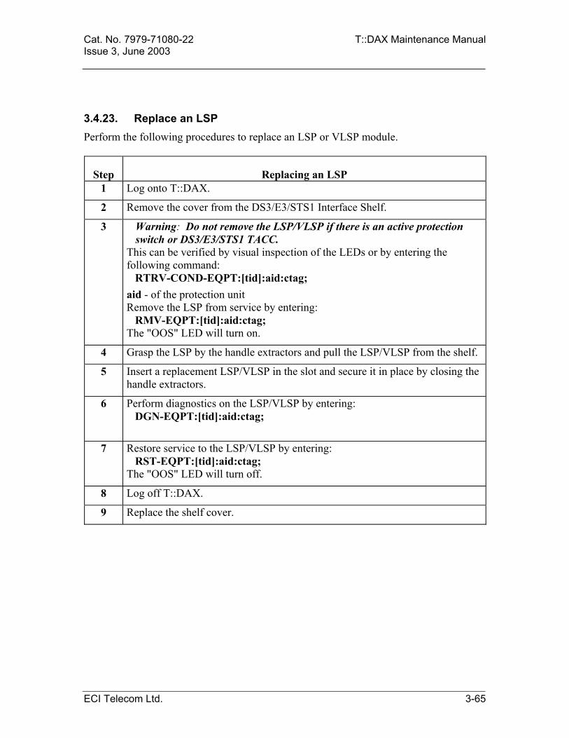
Cat. No. 7979-71080-22 T::DAX Maintenance Manual Issue 3, June 2003
3.4.23. Replace an LSP Perform the following procedures to replace an LSP or VLSP module.
Step Replacing an LSP 1 Log onto T::DAX.
2 Remove the cover from the DS3/E3/STS1 Interface Shelf.
3 Warning: Do not remove the LSP/VLSP if there is an active protection switch or DS3/E3/STS1 TACC.
This can be verified by visual inspection of the LEDs or by entering the following command: RTRV-COND-EQPT:[tid]:aid:ctag; aid - of the protection unit Remove the LSP from service by entering: RMV-EQPT:[tid]:aid:ctag; The "OOS" LED will turn on.
4 Grasp the LSP by the handle extractors and pull the LSP/VLSP from the shelf.
5 Insert a replacement LSP/VLSP in the slot and secure it in place by closing the handle extractors.
6 Perform diagnostics on the LSP/VLSP by entering: DGN-EQPT:[tid]:aid:ctag;
7 Restore service to the LSP/VLSP by entering: RST-EQPT:[tid]:aid:ctag; The "OOS" LED will turn off.
8 Log off T::DAX.
9 Replace the shelf cover.
ECI Telecom Ltd. 3-65
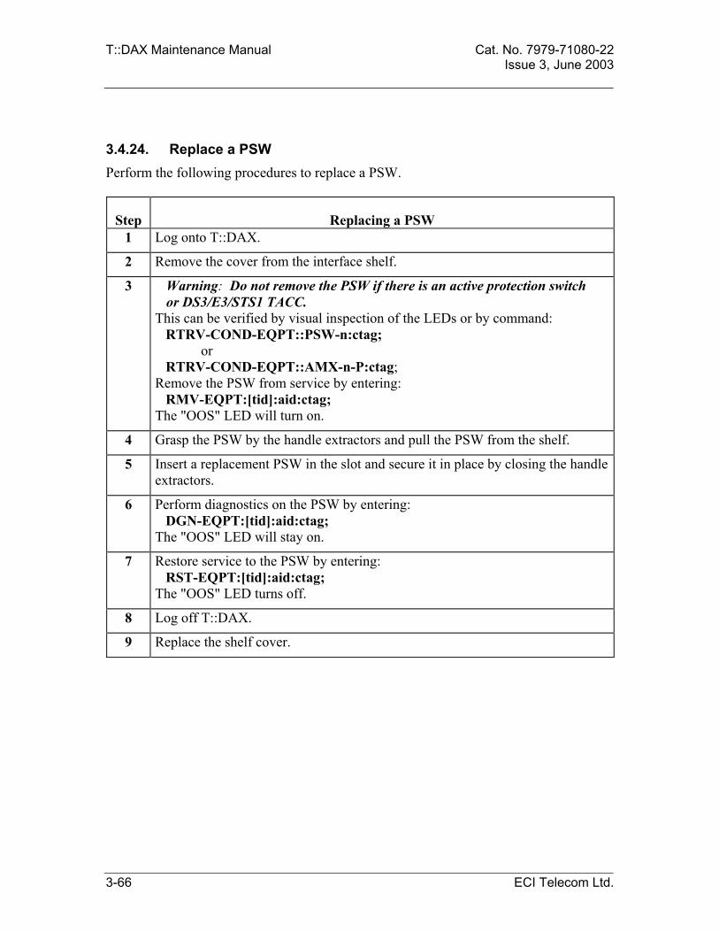
T::DAX Maintenance Manual Cat. No. 7979-71080-22 Issue 3, June 2003
3.4.24. Replace a PSW Perform the following procedures to replace a PSW.
Step Replacing a PSW 1 Log onto T::DAX.
2 Remove the cover from the interface shelf.
3 Warning: Do not remove the PSW if there is an active protection switch or DS3/E3/STS1 TACC.
This can be verified by visual inspection of the LEDs or by command: RTRV-COND-EQPT::PSW-n:ctag; or RTRV-COND-EQPT::AMX-n-P:ctag; Remove the PSW from service by entering: RMV-EQPT:[tid]:aid:ctag; The "OOS" LED will turn on.
4 Grasp the PSW by the handle extractors and pull the PSW from the shelf.
5 Insert a replacement PSW in the slot and secure it in place by closing the handle extractors.
6 Perform diagnostics on the PSW by entering: DGN-EQPT:[tid]:aid:ctag; The "OOS" LED will stay on.
7 Restore service to the PSW by entering: RST-EQPT:[tid]:aid:ctag; The "OOS" LED turns off.
8 Log off T::DAX.
9 Replace the shelf cover.
3-66 ECI Telecom Ltd.

Cat. No. 7979-71080-22 T::DAX Maintenance Manual Issue 3, June 2003
3.4.25. Replace a CBU Perform the following procedures to replace a CBU.
Step Replacing a CBU 1 Log onto T::DAX.
2 Remove the cover from the STS1/DS3/E3 Interface Shelf.
3 Note: Placing an active CBU in the maintenance state causes T::DAX to automatically switch the redundant CBU to the active state.
Remove the MCU from service by entering: RMV-EQPT:[tid]:aid:ctag; The "OOS" LED will turn on.
4 Loosen the screws, grasp the CBU by the handle extractors and pull the CBU from the shelf.
5 Insert a replacement CBU in the slot and secure it in place by closing the handle extractors and tightening the screws.
6 Perform diagnostics on the CBU by entering: DGN-EQPT:[tid]:aid:ctag;
7 Restore service to the CBU by entering: RST-EQPT:[tid]:aid:ctag; The "OOS" LED will turn off.
8 Log off T::DAX. 9 Replace the shelf cover.
ECI Telecom Ltd. 3-67

T::DAX Maintenance Manual Cat. No. 7979-71080-22 Issue 3, June 2003
3.4.26. Replace a DS3/E3/STS1 Interface Card Perform the following procedures to replace a DS3/E3/STS1 Interface card.
Step Replacing a DS3/E3/STS1 Interface Card 1 Log onto T::DAX. 2 Remove the cover from the DS3/E3/STS1 Interface Shelf containing the AMX
card to be removed. 3 For AMX-A through AMX-H: Before removing the AMX from service, make
sure AMX-P is not protecting any other AMX card in the shelf. For AMX-P: Before removing the card from service, make sure it is not protecting any other AMX card in the shelf. Remove the AMX from service by entering: RMV-EQPT:[tid]:aid:ctag::[mode]; mode – Specifies how the specified unit(s) will be removed from service: NORM – (default) removal request is executed only if it does not cause interruption of service. Otherwise, the request is denied. FRCD – Removal request is executed regardless of service interruption. This is required only if no protection unit is available. The ACT LED on the removed unit will turn off and the OOS LED will turn on. The ACT LED on the protection unit will turn on. The unit will switch to protection. This will be shown by LED A-H on the PSW card turning on. Verify the correct LED turns on before removing the card.
4 Grasp the card by both handle extractors and remove it from the shelf. 5 Insert a new AMX in the slot and secure it in place by closing both handle
extractors. 6 Perform diagnostics on the AMX by entering:
DGN-EQPT:[tid]:aid:ctag; 7 Restore service to the AMX by entering:
RST-EQPT:[tid]:aid:ctag; The OOS LED on the restored unit will turn off and the ACT LED will turn on. The ACT LED on the protection unit will turn off. LED A-H on the PSW will turn off.
8 Log off T::DAX. 9 Replace the shelf cover.
3-68 ECI Telecom Ltd.

Cat. No. 7979-71080-22 T::DAX Maintenance Manual Issue 3, June 2003 3.4.27. In Service Replacement of AAMX with DAMX/IAMX The following procedure describes how to replace, in-service, AAMX cards with DAMX or IAMX cards, and vice versa. The procedure describes the replacement of a single shelf.
Step Replacing an AAMX to DAMX/IAMX
1 Verify that the current ACP software is the release supporting the new card to be installed. Verify also that this software resides on AMU and disk.
RTRV-MEMSTAT-EQPT::ACP-A&-B&AMU&DSU:ctag; The response should be according to the appropriate product release note.
Verify that all required hardware items are available.
2 As a precaution, backup the database to disk.
CPY-MEM::FROMMEM=PRI,TOMEM=SEC:ctag::DATA;
3 For IAMX card connect the TMR cables to the shelf according to T::DAX installation manual. This should be done in the following order:
RTRV-COND-EQPT:: CDU-A&-B:ctag; Cables from the standby CDU should be connected and appropriate termination should be placed. Then switch to standby CDU.
SW-DX-EQPT::CDU-B:ctag; Cables from the active CDU should be connected and appropriate termination should be placed.
4 Verify that all AMX units to be replaced are active, in service and not protected. For example, if AMXs in shelf 5 are to be replaced, enter:
RTRV-COND-EQPT::AMX-5-A&&-H&-P:ctag;
5 Inhibit switching to protection to all AMX units to be replaced.
INH-SW-EQPT::AMX-5-A:ctag::PROTN;
INH-SW-EQPT::AMX-5-B:ctag::PROTN;
INH-SW-EQPT::AMX-5-H:ctag::PROTN;
ECI Telecom Ltd. 3-69

T::DAX Maintenance Manual Cat. No. 7979-71080-22 Issue 3, June 2003
Step Replacing an AAMX to DAMX/IAMX
6 If VLSP is not already installed in the shelf, for each LSP in the shelf, remove it from service, replace it with VLSP and restore it to service:
RMV-EQPT::LSP-5-A:ctag; Plug out LSP and plug in VLSP instead.
RST-EQPT::LSP-5-A:RSTA;
7 Delete the standby MCU:
DLT-EQPT::MCU-5-B:ctag;
8 Plug out the standby MCU.
9 Change the MCU type to the new relevant type. For example, if HAMX should be replaced by DAMX enter:
ED-EQPT::MCU-5-A:ctag::DMCU:RUSURE=Y;
10 All AMXs in the shelf will be alarmed as MISMEQPT. T::DAX will issue a PRGRM alarm regarding the PSW.
11 Verify that program was copied correctly to MCU:
RTRV-MEMSTAT-EQPT::MCU-5-A:ctag; The response should be according to the appropriate product release note.
12 For IAMX card plug in CBU. T::DAX will issue a plug in message regarding CBUs.
13 Enter the newly plugged-in CBUs, if any:
ENT-EQPT::CBU-5-A:ctag;
ENT-EQPT::CBU-5-B:ctag;
14 Remove the protection AMX from service, replace it with the new AMX type and restore it to service:
RMV-EQPT::AMX-5-P:ctag; T::DAX will issue a MISMEQPT clear alarm report for the removed AMX. Plug out protection AMX and plug in the new AMX instead.
RST-EQPT::AMX-5-P:ctag;
3-70 ECI Telecom Ltd.

Cat. No. 7979-71080-22 T::DAX Maintenance Manual Issue 3, June 2003
Step Replacing an AAMX to DAMX/IAMX
15 Allow switching to protection of AMX-A:
ALW-SW-EQPT::AMX-5-A:ctag::PROTN;
Wait until AMX-A switches to the protection AMX.
16 Remove the AMX-A from service, replace it with the new AMX type and restore it to service:
RMV-EQPT::AMX-5-A:ctag; T::DAX will issue a MISMEQPT clear alarm report for the removed AMX.
Plug out AMX-A and plug in the new AMX instead.
RST-EQPT::AMX-5-A:ctag;
T::DAX will issue a REPT-SW report when protection AMX switches back to AMX-A.
17 Repeat last two steps for each remaining AMX, from AMX-B to AMX-H.
18 Provision the standby MCU previously deleted and plugged out. Do not plug it in yet:
ENT-EQPT::MCU-5-B:ctag::DMCU::OOS,AINS;
19 Plug in the standby MCU and wait for T::DAX to issue a plug-in report.
20 Verify that program was copied correctly to the MCUs:
RTRV-MEMSTAT-EQPT::MCU-5-A&-B:ctag; The response should be according to the appropriate product release note.
21 Switch MCU to the standby by MCU and verify no alarms:
SW-DX-EQPT::MCU-5-B:ctag:::RUSURE=Y;
22 Switch CBU to the standby CBU and verify no alarms:
SW-DX-EQPT::CBU-5-B:ctag:::RUSURE=Y;
ECI Telecom Ltd. 3-71
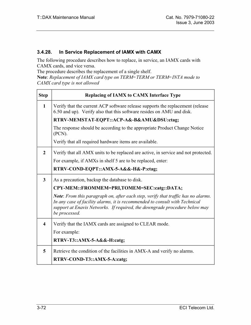
T::DAX Maintenance Manual Cat. No. 7979-71080-22 Issue 3, June 2003
3.4.28. In Service Replacement of IAMX with CAMX The following procedure describes how to replace, in service, an IAMX cards with CAMX cards, and vice versa. The procedure describes the replacement of a single shelf. Note: Replacement of IAMX card type on TERM=TERM or TERM=INTA mode to CAMX card type is not allowed
Step Replacing of IAMX to CAMX Interface Type
1 Verify that the current ACP software release supports the replacement (release 6.50 and up). Verify also that this software resides on AMU and disk.
RTRV-MEMSTAT-EQPT::ACP-A&-B&AMU&DSU:ctag;
The response should be according to the appropriate Product Change Notice (PCN).
Verify that all required hardware items are available.
2 Verify that all AMX units to be replaced are active, in service and not protected.
For example, if AMXs in shelf 5 are to be replaced, enter:
RTRV-COND-EQPT::AMX-5-A&&-H&-P:ctag;
3 As a precaution, backup the database to disk.
CPY-MEM::FROMMEM=PRI,TOMEM=SEC:catg::DATA; Note: From this paragraph on, after each step, verify that traffic has no alarms. In any case of facility alarms, it is recommended to consult with Technical support at Enavis Networks. If required, the downgrade procedure below may be processed.
4 Verify that the IAMX cards are assigned to CLEAR mode.
For example:
RTRV-T3::AMX-5-A&&-H:catg;
5 Retrieve the condition of the facilities in AMX-A and verify no alarms.
RTRV-COND-T3::AMX-5-A:catg;
3-72 ECI Telecom Ltd.

Cat. No. 7979-71080-22 T::DAX Maintenance Manual Issue 3, June 2003
Step Replacing of IAMX to CAMX Interface Type
6 Remove the AMX-A from service, replace it with the new AMX type:
RMV-EQPT::AMX-5-A:catg;
Wait until AMX-A switches to the protection AMX.
Plug out AMX-A and plug in the new AMX instead.
7 Change the AMX type to the new relevant type. For example:
ED-T3::AMX-5-A:ctag::TYPE=CAMX; or
ED-T3:AMX-5-A:ctag::TYPE=IAMX;
8 Restore the unit to service:
RST-EQPT::AMX-5-A:ctag; T::DAX will issue a REPT-SW report when service is switched back from protection AMX.
9 Retrieve the condition of the facilities in AMX-A and verify no alarms.
RTRV-COND-T3::AMX-5-A:ctag;
10 If required, allow alarm report on T3:
ED-T3::AMX-5-A:ctag:::ALMREPT=ALW; Verify no alarms.
11 Repeat the procedure form step 4 for each remaining AMX which should be replaced
ECI Telecom Ltd. 3-73

T::DAX Maintenance Manual Cat. No. 7979-71080-22 Issue 3, June 2003
3.4.29. Replace an ECU Perform the following procedures to replace an ECU.
Step Replacing an ECU
1 Log onto T::DAX.
2 Remove the cover from the Interface Shelf.
3 If the ECU to be replaced is currently active, switch to the currently standby unit by entering: SW-DX-EQPT:[tid]:aid:ctag:::RUSURE=Y; aid –aid of the unit that will become active after completion of the switch.
4 Remove the ECU from service by entering: RMV-EQPT:[tid]:aid:ctag; The “OOS” LED will turn on.
5 Grasp the ECU by the handle extractors and pull it from the shelf. 6 Insert a replacement ECU in the slot and secure it in place by closing the
handle extractors.
7 Perform diagnostics on the ECU by entering: DGN-EQPT:[tid]:aid:ctag; The "OOS" LED will go out during the diagnostics.
8 Restore service to the ECU by entering: RST-EQPT:[tid]:aid:ctag; The OOS LED will turn off. The time period required for this process to complete depends on the number of ports and cross connects in the shelf.
9 Log off T::DAX. 10 Replace the shelf cover.
3-74 ECI Telecom Ltd.

Cat. No. 7979-71080-22 T::DAX Maintenance Manual Issue 3, June 2003
3.4.30. Replace a PSM Perform the following procedures to replace a PSM Interface card.
Step Replacing a PSM Interface Card 1 Log onto T::DAX. 2 Remove the cover from the High Density DS3 Interface Shelf. 3 Warning: Do not remove the PSM if there is an active protection switch or
DS3 TACC. Remove the PSM card from service and place it in maintenance state, enter: RMV-EQPT:[tid]:aid:ctag; The “OOS” LED will turn on.
4 Grasp the card by both handle extractors and remove it from the shelf. 5 Insert a new PSM in the slot and secure it in place by closing both handle
extractors. 6 Perform diagnostics on the PSM by entering:
DGN-EQPT:[tid]:aid:ctag;
7 Restore service to the PSM card, enter: RST-EQPT:[tid]:aid:ctag; The “OOS” LED will turn off.
8 Log off T::DAX. 9 Replace the shelf cover.
ECI Telecom Ltd. 3-75

T::DAX Maintenance Manual Cat. No. 7979-71080-22 Issue 3, June 2003
3.4.31. Replace a TSP Perform the following procedures to replace a TSP Interface card.
Step Replacing an TSP 1 Log onto T::DAX. 2 Remove the cover from the DS3 Interface Shelf. 3 Warning: Do not remove the TSP if there is an active protection switch.
This can be verified by visual inspection of the LEDs or by entering the following command: RTRV-COND-EQPT:[tid]:aid:ctag; aid - of the protection unit Remove the TSP from service by entering: RMV-EQPT:[tid]:aid:ctag; The "OOS" LED will turn on.
4 Grasp the TSP by the handle extractors and pull the TSP from the shelf. 5 Insert a replacement TSP in the slot and secure it in place by closing the handle
extractors. 6 Perform diagnostics on the TSP by entering:
DGN-EQPT:[tid]:aid:ctag;
7 Restore service to the TSP by entering: RST-EQPT:[tid]:aid:ctag; The "OOS" LED will turn off.
8 Log off T::DAX. 9 Replace the shelf cover.
3-76 ECI Telecom Ltd.

Cat. No. 7979-71080-22 T::DAX Maintenance Manual Issue 3, June 2003
3.4.32. Replace a TMX Interface Card Perform the following procedures to replace a TMX Interface card.
Step Replacing a TMX Interface Card 1 Log onto T::DAX. 2 Remove the cover from the DS3 Interface Shelf containing the TMX card to be
removed. 3 For TMX-A through TMX-H: Before removing the TMX from service, make
sure AMX-P is not protecting any other TMX card in the shelf. For TMX-P: Before removing the card from service, make sure it is not protecting any other TMX card in the shelf. Remove the TMX from service by entering: RMV-EQPT:[tid]:aid:ctag::[mode]; mode – Specifies how the specified unit(s) will be removed from service: NORM – (default) removal request is executed only if it does not cause interruption of service. Otherwise, the request is denied. FRCD – Removal request is executed regardless of service interruption. This is required only if no protection unit is available. The ACT LED on the removed unit will turn off and the OOS LED will turn on. The ACT LED on the protection unit will turn on. The unit will switch to protection. This will be shown by LED PROT on the PSM card turning on. Verify the correct LED turns on before removing the card.
4 Grasp the card by both handle extractors and remove it from the shelf. 5 Insert a new TMX in the slot and secure it in place by closing both handle
extractors. 6 Perform diagnostics on the TMX by entering:
DGN-EQPT:[tid]:aid:ctag; 7 Restore service to the TMX by entering:
RST-EQPT:[tid]:aid:ctag; The OOS LED on the restored unit will turn off and the ACT LED will turn on. The ACT LED on the protection unit will turn off. LED PROT on the PSM will turn off.
8 Log off T::DAX. 9 Replace the shelf cover.
ECI Telecom Ltd. 3-77

T::DAX Maintenance Manual Cat. No. 7979-71080-22 Issue 3, June 2003
3.4.33. Replace an OCU Perform the following procedures to replace an OCU.
Step Replacing an OCU
1 Log onto T::DAX. 2 Remove the cover from the STM1/OC3 Interface Shelf containing the OCU
card to be removed.
3 If the OCU to be replaced is currently active, switch to the currently standby unit by entering:
SW-DX-EQPT:[tid]:aid:ctag:::RUSURE=Y; aid - the unit that will become active after completion of the switch.
4 Remove the OCU from service by entering: RMV-EQPT:[tid]:aid:ctag;
5 Grasp the OCU by the handle extractors and pull it from the shelf. 6 Insert a replacement OCU in the slot and secure it in place by closing the
handle extractors.
7 Retrieve the program version of the new OCU card by entering: RTRV-MEMSTAT-EQTP:[tid]:aid:ctag;
8 If necessary, copy the OCU card program from the disk to the OCU card by entering:
CPY-MEM:[tid]:FROMMEM=SEC,TOMEM=WKG, TODEV=todev:ctag::PGM:[REL=rel];
todev - AID format for the OCU card to be downloaded. rel - current release number.
9 Perform diagnostics on the OCU by entering:
DGN-EQPT:[tid]:aid:ctag;
10 Restore service to the OCU by entering:
RST-EQPT:[tid]:aid:ctag;
11 Log off T::DAX.
12 Replace the shelf cover.
3-78 ECI Telecom Ltd.

Cat. No. 7979-71080-22 T::DAX Maintenance Manual Issue 3, June 2003
3.4.34. Replace an HR3 Interface Card Perform the following procedures to replace an HR3 Interface card.
Step Replacing an HR3 Interface Card
1 Log onto T::DAX. 2 Remove the cover from the STM1/OC3 Interface Shelf. 3 Remove the HR3 card from service and place it in maintenance state, enter:
RMV-EQPT:[tid]:aid:ctag; The “OOS” LED will turn on.
4 Warning: Laser radiation may be emitted from the optical cable. Avoid direct eye exposure.
Grasp the card by both handle extractors and pull the card half way out (until it latches). Disconnect the cables from R and T connectors on the right side of the HR3 card. Push the card clamp up (which is located on the bottom right side of the card), in order to release the card from the shelf and pull out the card.
5 Warning: Laser radiation may be emitted from the optical cable. Avoid direct eye exposure.
Insert the replacement HR3 in the slot until half way. Connect the cables to the R and T connectors on the right side of the HR3 card. Continue inserting the card and secure it in place by closing both handle extractors.
6 Retrieve the program version of the new HR3 card by entering: RTRV-MEMSTAT-EQTP:[tid]:aid:ctag;
7 If necessary, copy the HR3 program from the disk to the HR3 card, enter: CPY-MEM:[tid]:FROMMEM=SEC,TOMEM=WKG,TODEV=todev:ctag:: PGM:[REL=rel]; todev - AID format for the HR3 card to be downloaded. rel - current release number.
8 Perform diagnostics on the HR3 by entering: DGN-EQPT:[tid]:aid:ctag;
aid - AID format for the HR3 card. 9 Restore service to the HR3 card, enter:
RST-EQPT:[tid]:aid:ctag; aid - AID format for the HR3 card.
The “OOS” LED will turn off. 10 Log off T::DAX.
11 Replace the shelf cover.
ECI Telecom Ltd. 3-79

T::DAX Maintenance Manual Cat. No. 7979-71080-22 Issue 3, June 2003
3.4.35. Replace an SMX/MSMX Interface Card Perform the following procedures to replace an SMX Interface card.
Step Replacing an SMX Interface Card
1 Log onto T::DAX.
2 Remove the cover from the STM1/OC3 Interface Shelf containing the SMX card to be removed.
2 For SMX-A through SMX-C: Before removing the SMX from service, make sure SMX-P is not protecting any other SMX card in that specific port. For SMX-P: Before removing the card from service, make sure it is not protecting any other SMX card in that specific port. Remove the SMX from service by entering: RMV-EQPT:[tid]:aid:ctag; The ACT LED on the removed unit will turn off and the OOS LED will turn on. The ACT LED on the protection unit will turn on.
3 Grasp the card by both handle extractors and remove it from the shelf.
4 Insert a new SMX in the slot and secure it in place by closing both handle extractors.
5 Retrieve the program version of the new SMX card by entering: RTRV-MEMSTAT-EQTP:[tid]:aid:ctag;
6 If necessary, copy the SMX card program from the disk to the SMX: CPY-MEM:[tid]:FROMMEM=SEC,TOMEM=WKG,TODEV=todev:ctag:: PGM:[REL=rel];
todev - AID format for the SMX card to be downloaded. rel - current release number - three digits.
7 Perform diagnostics on the SMX by entering: DGN-EQPT:[tid]:aid:ctag;
8 Restore service to the SMX by entering: RST-EQPT:[tid]:aid:ctag;
The OOS LED on the restored unit will turn off and the ACT LED will turn on. The ACT LED on the protection unit will turn off.
10 Log off T::DAX.
11 Replace the shelf cover.
3-80 ECI Telecom Ltd.

Cat. No. 7979-71080-22 T::DAX Maintenance Manual Issue 3, June 2003
3.4.36. Replace a TRP Perform the following procedures to replace a TRP.
Step Replacing a TRP
1 Log onto T::DAX.
2 Remove the cover from the STM1/OC3 Interface Shelf containing the TRP card to be removed.
3 Warning - Do not remove the TRP if there is an active protection switch.
This can be verified by visual inspection of the LEDs or by entering the following command:
RTRV-COND-EQPT:[tid]:aid:ctag; aid - of the protection unit.
Remove the TRP from service by entering:
RMV-EQPT:[tid]:aid:ctag;
4 Grasp the TRP by the handle extractors and pull it from the shelf.
5 Insert a replacement TRP in the slot and secure it in place by closing the handle extractors.
6 Perform diagnostics on the TRP by entering:
DGN-EQPT:[tid]:aid:ctag;
7 Restore service to the TRP by entering:
RST-EQPT:[tid]:aid:ctag;
8 Log off T::DAX.
9 Replace the shelf cover.
ECI Telecom Ltd. 3-81

T::DAX Maintenance Manual Cat. No. 7979-71080-22 Issue 3, June 2003
3.4.37. Replace an RCU Perform the following procedures to replace an RCU.
Step Replacing an RCU
1 Log onto T::DAX.
2 Remove the cover from the Interface Shelf.
3 If the RCU to be replaced is currently active, switch to the currently standby unit by entering: SW-DX-EQPT:[tid]:aid:ctag:::RUSURE=Y; aid –aid of the unit that will become active after completion of the switch.
4 Remove the RCU from service by entering: RMV-EQPT:[tid]:aid:ctag;
The “OOS” LED will turn on.
5 Grasp the RCU by the handle extractors and pull it from the shelf.
6 Insert a replacement RCU in the slot and secure it in place by closing the handle extractors.
7 Retrieve the program version of the new RCU card by entering: RTRV-MEMSTAT-EQTP:[tid]:aid:ctag;
8 If necessary, copy the RCU card program from the disk to the RCU card by entering:
CPY-MEM:[tid]:FROMMEM=SEC,TOMEM=WKG, TODEV=todev:ctag::PGM:[REL=rel];
todev - AID format for the RCU card to be downloaded. rel - current release number - three digits.
9 Wait for 30 seconds following COMPLD response
10 Perform diagnostics on the RCU by entering: DGN-EQPT:[tid]:aid:ctag;
11 Restore service to the RCU by entering: RST-EQPT:[tid]:aid:ctag;
12 Log off T::DAX.
13 Replace the shelf cover.
3-82 ECI Telecom Ltd.

Cat. No. 7979-71080-22 T::DAX Maintenance Manual Issue 3, June 2003
3.4.38. Replace an SMC Interface Card Perform the following procedures to replace an SMC interface card.
Step Replacing an SMC Interface Card
1 Log onto T::DAX.
2 Remove the cover from the High Density STM1/OC3 Interface Shelf.
3 Remove the SMC card from service and place it in maintenance state, enter:
RMV-EQPT:[tid]:aid:ctag; The “OOS” LED will turn on.
4 Grasp the card by both handle extractors and remove it from the shelf.
5 Insert a new SMC in the slot and secure it in place by closing both handle extractors.
6 Perform diagnostics on the SMC by entering:
DGN-EQPT:[tid]:aid:ctag;
7 Restore service to the SMC card, enter:
RST-EQPT:[tid]:aid:ctag; The “OOS” LED will turn off.
8 Log off T::DAX.
9 Replace the shelf cover.
ECI Telecom Ltd. 3-83

T::DAX Maintenance Manual Cat. No. 7979-71080-22 Issue 3, June 2003
3.4.39. Replace an LHR/CHR Interface Card Perform the following procedures to replace an LHR/CHR Interface card.
Step Replacing an LHR/CHR Interface Card
1 Log onto T::DAX.
2 Remove the cover from the interface shelf
3 Remove the LHR/CHR from service by entering:
RMV-EQPT:[tid]:aid:ctag; The “OOS” LED will turn on.
4 Warning: Laser radiation may be emitted from the optical cable. Avoid direct eye exposure.
Grasp the card by both handle extractors and pull the card half way out. Disconnect the cables from R and T connectors on the right side of the LHR/CHR card and pull out the card.
5 Warning: Laser radiation may be emitted from the optical cable. Avoid direct eye exposure.
Insert the replacement LHR/CHR in the slot until half way. Connect the cables to the R and T connectors on the right side of the LHR/CHR card. Continue inserting the card and secure it in place by closing both handle extractors.
8 Perform diagnostics on the LHR/CHR by entering:
DGN-EQPT:[tid]:aid:ctag;
9 Restore service to the LHR/CHR by entering:
RST-EQPT:[tid]:aidp:ctag; The “OOS” LED will turn off.
10 Log off T::DAX.
11 Replace the shelf cover.
3-84 ECI Telecom Ltd.

Cat. No. 7979-71080-22 T::DAX Maintenance Manual Issue 3, June 2003
3.4.40. Replace an MIU Perform the following procedures to replace an MIU Interface card.
Step Replacing an MIU Interface Card
1 Log onto T::DAX.
2 Remove the cover from the Interface Shelf
3 Remove the MIU from service by entering:
RMV-EQPT:[tid]:aid:ctag; The “OOS” LED will turn on.
4 Grasp the card by both handle extractors and remove it from the shelf.
5 Insert a new MIU in the slot and secure it in place by closing both handle extractors.
6 Perform diagnostics on the MIU by entering:
DGN-EQPT:[tid]:aid:ctag;
aid - AID format for the MIU card.
7 Restore service to the MIU by entering:
RST-EQPT:[tid]:aidp:ctag; The OOS LED on the restored unit will turn off and the ACT LED will turn on. The ACT LED on the protection unit will turn off.
8 Log off T::DAX.
9 Replace the shelf cover.
ECI Telecom Ltd. 3-85

T::DAX Maintenance Manual Cat. No. 7979-71080-22 Issue 3, June 2003
3.4.41. Replace an SM4 Interface Card Perform the following procedures to replace an SM4 Interface card.
Step Replacing an SM4 Interface Card
1 Log onto T::DAX.
2 Remove the cover from the OC12/STM4 Interface Shelf.
3 Remove the SM4 card from service and place it in maintenance state, enter: RMV-EQPT:[tid]:aid:ctag;
The “OOS” LED will turn on.
4 Warning: Laser radiation may be emitted from the optical cable. Avoid direct eye exposure.
Grasp the card by both handle extractors and pull the card half way out. Disconnect the cables from R and T connectors on the right side of the SM4 card and pull out the card.
5 Insert the replacement SM4 in the slot until half way. Connect the cables to the R and T connectors on the right side of the SM4 card. Continue inserting the card and secure it in place by closing both handle extractors.
6 Retrieve the program version of the new SM4 card by entering: RTRV-MEMSTAT-EQTP:[tid]:aid:ctag;
7 If necessary, copy the SM4 program from the disk to the SM4 card, enter: CPY-MEM:[tid]:FROMMEM=SEC, TOMEM=WKG, TODEV=todev:ctag::PGM:[REL=rel]; todev - AID format for the SM4 card to be downloaded. rel - current release number - three digits.
8 Perform diagnostics on the SM4 by entering: DGN-EQPT:[tid]:aid:ctag;
9 Restore service to the SM4 card, enter: RST-EQPT:[tid]:aid:ctag;
The “OOS” LED will turn off.
10 Log off T::DAX.
11 Replace the shelf cover.
3-86 ECI Telecom Ltd.

Cat. No. 7979-71080-22 T::DAX Maintenance Manual Issue 3, June 2003
3.4.42. Replace an IHR/MHR Perform the following procedures to replace an IHR/MHR interface card.
Step Replacing an IHR/MHR Interface Card
1 Log onto T::DAX.
2 Remove the cover from the interface shelf
3 Remove the IHR/MHR from service by entering:
RMV-EQPT:[tid]:aid:ctag; The “OOS” LED will turn on.
4 Grasp the card by both handle extractors and remove it from the shelf.
5 Insert a new IHR/MHR in the slot and secure it in place by closing both handle extractors.
6 Perform diagnostics on the IHR/MHR by entering:
DGN-EQPT:[tid]:aid:ctag;
7 Restore service to the IHR/MHR by entering:
RST-EQPT:[tid]:aidp:ctag; The OOS LED on the restored unit will turn off and the ACT LED will turn on. The ACT LED on the protection unit will turn off.
8 Log off T::DAX.
9 Replace the shelf cover.
ECI Telecom Ltd. 3-87

T::DAX Maintenance Manual Cat. No. 7979-71080-22 Issue 3, June 2003
3.4.43. Replace an NBU Perform the following procedures to replace an NBU card.
Step Replacing an NBU Card
1 Log onto T::DAX.
2 Remove the cover from the Narrowband Shelf containing the NBU card to be removed.
3 Before removing the NBU from service, make sure the protection NBU is not protecting any other NBU card in the shelf
Warning: The Narrowband shelf can be provisioned to operate without protection NBU. In this case, removing NBU card from service will cause service interruption.
Remove the NBU from service by entering: RMV-EQPT:[tid]:aid:ctag::[mode]; mode – Specifies how the specified unit(s) will be removed from service: NORM – (default) only if it does not cause interruption of service. FRCD –regardless of service interruption. This is required only if no protection unit is available. The NBU card will switch to protection. The ACT LED on the removed unit will turn off and the OOS LED will turn on. The ACT LED on the protection unit will turn on.
4 Grasp the card by both handle extractors and remove it from the shelf.
5 Insert a new NBU in the slot and secure it in place by closing both handle extractors.
6 Perform diagnostics on the NBU by entering: DGN-EQPT:[tid]:aid:ctag;
7 Restore service to the NBU by entering: RST-EQPT:[tid]:aid:ctag; The OOS LED on the restored unit will turn off and the ACT LED will turn on. The ACT LED on the protection unit will turn off.
8 Log off T::DAX.
9 Replace the Narrowband Shelf cover.
3-88 ECI Telecom Ltd.
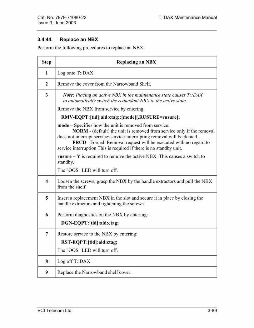
Cat. No. 7979-71080-22 T::DAX Maintenance Manual Issue 3, June 2003 3.4.44. Replace an NBX Perform the following procedures to replace an NBX.
Step Replacing an NBX
1 Log onto T::DAX.
2 Remove the cover from the Narrowband Shelf.
3 Note: Placing an active NBX in the maintenance state causes T::DAX to automatically switch the redundant NBX to the active state.
Remove the NBX from service by entering:
RMV-EQPT:[tid]:aid:ctag::[mode][,RUSURE=rusure];
mode – Specifies how the unit is removed from service: NORM - (default) the unit is removed from service only if the removal does not interrupt service; service-interrupting removal will be denied. FRCD - Forced. Removal request will be executed with no regard to service interruption This is required if there is no standby unit.
rusure = Y is required to remove the active NBX. This causes a switch to standby.
The "OOS" LED will turn off.
4 Loosen the screws, grasp the NBX by the handle extractors and pull the NBX from the shelf.
5 Insert a replacement NBX in the slot and secure it in place by closing the handle extractors and tightening the screws.
6 Perform diagnostics on the NBX by entering:
DGN-EQPT:[tid]:aid:ctag;
7 Restore service to the NBX by entering:
RST-EQPT:[tid]:aid:ctag;
The "OOS" LED will turn off.
8 Log off T::DAX.
9 Replace the Narrowband shelf cover.
ECI Telecom Ltd. 3-89

T::DAX Maintenance Manual Cat. No. 7979-71080-22 Issue 3, June 2003
3.4.45. Replace an NCU Perform the following procedures to replace an NCU.
Step Replacing an NCU
1 Log onto T::DAX.
2 Remove the cover from the Narrowband Shelf.
3 If the NCU to be replaced is currently active, switch to the currently standby unit by entering: INIT-SYS::aid:ctag::0:RUSURE=Y; aid – of the unit that will become active after completion of the switch.
4 Remove the NCU from service by entering: RMV-EQPT::aid:ctag::[mode]:RUSURE=rusure ; mode – Specifies how the unit is removed from service: NORM - (default) only if the removal does not interrupt service. FRCD – Removed regardless of service interruption. This is required only if no standby unit is available. rusure – Enter Y to remove unconditionally or N (default) to deny the command if the request will remove an active processor. The "OOS" LED on the removed NCU will turn on and the (previous) standby unit will now be active and its "ACT" LED will go on.
5 Grasp the NCU by the handle extractors and pull the NCU from the shelf.
6 Insert a replacement MCU in the slot and secure it in place by closing the handle extractors.
7 Perform diagnostics on the NCU by entering: DGN-EQPT::aid:ctag; The "OOS" LED will momentarily turn on.
8 Restore service to the NCU by entering: RST-EQPT::aid:ctag; The "OOS" LED will turn off.
9 Log off T::DAX.
10 Replace the Narrowband shelf cover.
3-90 ECI Telecom Ltd.

Cat. No. 7979-71080-22 T::DAX Maintenance Manual Issue 3, June 2003
3.4.46. Interchanging NBU cards The following procedure describes how to interchange, in-service, the different types of NBU cards: ENBU with TNBU and ANBU with UNBU, and vice versa. The procedure describes the replacement of a single shelf. Note: 1. The cards interchange procedure requires deleting and reentering the T0/E0, T1/E1 cross-connections. Obtaining a maintenance window is mandatory! 2. In order to minimize the outage, prepare scripts for deleting and reentering the equipment / facilities and cross-connection.
Step Interchanging NBU cards
1 Log onto T::DAX
2 Remove the cover from the shelf containing the NBU card to be changed.
3 Perform database backup before the starting the card replacement.
a. Insert a tape into the TPDR, and enter the following commands to initialize the tape:
RMV-EQPT:: TPDR:L::FRCD;
INIT-SYS::TPDR:L::0:RUSURE=Y;
RST-EQPT:: TPDR:L; b. Enter the following commands to back up the database:
CPY-MEM::FROMMEM=PRI,TOMEM=SEC:L::DATA;
CPY-MEM::FROMMEM=PRI,TOMEM=AUX:L::DATA; c. Enter the following commands to verify the database backup:
RTRV-DIR-EQPT::DSU:DB;
RTRV-DIR-EQPT::TPDR:DB; d. Label the tape as ”Database of Release” and note the system ID, date and
time.
ECI Telecom Ltd. 3-91

T::DAX Maintenance Manual Cat. No. 7979-71080-22 Issue 3, June 2003
Step Interchanging NBU cards
4 Enter the following commands to retrieve the cross-connect of the NBU card to be changed:
RTRV-CRS-T0/E0::[from]:ctag;
RTRV-CRS-T1/E1::[from] :ctag; from (for T0/E0) - shelf number - NBU card designation (A-H) - T1/E1
number (1-28) - Time slot number (1-24 for T1, 1-31 for E1) from (for T1/E1) – T1/E1 AID address For example: RTRV-CRS-E0::6-A-1-1&&-31:L; RTRV-CRS-E1::6-A-1 :L;
5 Enter the following command to delete existing cross-connects from the NBU card that needs to be changed:
DLT-CRS-T0/E0::[shelf]-[NBU]-[T1/E1]-[TS], [shelf]-[NBU]-[T1/E1]-[TS]:ctag:: [cct];
shelf - logical shelf number NBU - NBU card designation (A-H) T1/E1 - T1/E1 number (1-28) TS - Time slot number (1-24 for T1, 1-31 for E1) cct - Cross connect type For example: DLT-CRS-E0::6-A-1-1,6-B-1-1:L;
Note: ”Grouping” is allowed
6 Enter the following command to delete existing E1/T1 cross-connects from the NBU card that needs to be changed:
DLT-CRS-T1/E1::[shelf]-[row]-[column], [shelf]-[NBU]-[T1/E1]:ctag;
shelf - logical shelf number row – T1/E1 row number(A-H) column – E1/T1 column number (1-28) NBU - NBU card designation (A-H) T1/E1 - T1/E1 number (1-28) For example: DLT-CRS-E1::1-A-1,6-B-1:L;
Note: ”Grouping” is allowed
3-92 ECI Telecom Ltd.

Cat. No. 7979-71080-22 T::DAX Maintenance Manual Issue 3, June 2003
Step Interchanging NBU cards
7 Enter the following command to delete the associated T1/E1s:
DLT-T1/E1::[shelf]-[NBU]-[T1/E1]:ctag;
shelf - logical shelf number NBU - NBU card designation (A-H) T1/E1 - T1/E1 number (1-28) For example: DLT-E1::6-A-1:L; DLT-T1::5-B-3:L;
Note: ”Grouping” is allowed
8 Enter the following command to delete the associated NBU cards:
DLT-EQPT:[tid]:aid:ctag; aid - NBU card designation (A-H) - shelf number – NBU number
9 Enter the following command to enter the new NBU card:
ENT-EQPT:[tid]:aid:ctag:: [type];
aid - NBU card designation (A-H) - shelf number – NBU number type - NBU card type (ENBU, TNBU, .ANBU, or UNBU) For example: ENT-EQPT::NBU-5-F:L::ENBU;
10 Enter the following command to provision the T1 / E1 ports.
ENT-T1/E1:: [shelf]-[NBU]-[trib]:ctag; shelf - logical shelf number NBU - NBU card designation (A-H) T1/E1 - T1/E1 number (1-28) For example: ENT-E1::5-F-1:L;
ECI Telecom Ltd. 3-93

T::DAX Maintenance Manual Cat. No. 7979-71080-22 Issue 3, June 2003
Step Interchanging NBU cards
11 Enter the following command to redefine the E1/T1 level cross-connects that were deleted in step 6:
ENT-CRS-T1/E1::[shelf]-[row]-[column], [shelf]-[NBU]-[T1/E1]:ctag;
shelf - logical shelf number row – T1/E1 row number(A-H) column – E1/T1 column number (1-28) NBU - NBU card designation (A-H) T1/E1 - T1/E1 number (1-28) For example: DLT-CRS-E1::1-A-1,6-B-1:L; Note: ”Grouping” is allowed
12 Enter the following command to redefine the cross-connects that were deleted in step 5:
ENT-CRS-T0/E0::[shelf]-[NBU]-[T1/E1]-[TS], [shelf]-[NBU]-[T1/E1]-[TS]:ctag:: [cct];
shelf - logical shelf number NBU - NBU card designation (A-H) T1/E1 - T1/E1 number (1-28) TS - Time slot number (1-24 for T1, 1-31 for E1) cct - Cross connect type For example: DLT-CRS-E0::6-A-1-1,6-B-1-1:L; Note: ”Grouping” is allowed
13 Initialize the control unit (NCU) on the shelf
a. Enter the following command to retrieve the condition of the NCU on the shelf:
RTRV-COND-EQPT::NCU-shelf-A&-B:L; shelf - logical shelf number
b. Initialize the active NCU card:
INIT-SYS::NCU-shelf-A:L::0:RUSURE=Y; Wait for a COMPLD response.
14 Plug out the NBU card and wait for a plug-out message.
15 Plug in the NBU card and wait for a plug-in message.
3-94 ECI Telecom Ltd.
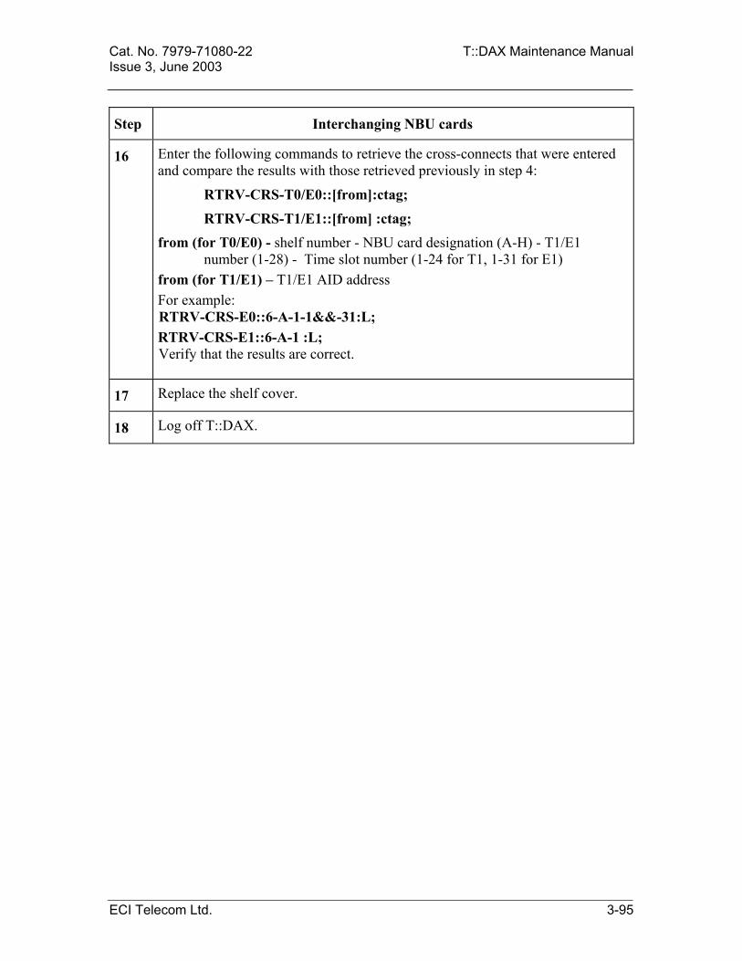
Cat. No. 7979-71080-22 T::DAX Maintenance Manual Issue 3, June 2003
Step Interchanging NBU cards
16 Enter the following commands to retrieve the cross-connects that were entered and compare the results with those retrieved previously in step 4:
RTRV-CRS-T0/E0::[from]:ctag;
RTRV-CRS-T1/E1::[from] :ctag; from (for T0/E0) - shelf number - NBU card designation (A-H) - T1/E1
number (1-28) - Time slot number (1-24 for T1, 1-31 for E1) from (for T1/E1) – T1/E1 AID address For example: RTRV-CRS-E0::6-A-1-1&&-31:L; RTRV-CRS-E1::6-A-1 :L; Verify that the results are correct.
17 Replace the shelf cover.
18 Log off T::DAX.
ECI Telecom Ltd. 3-95
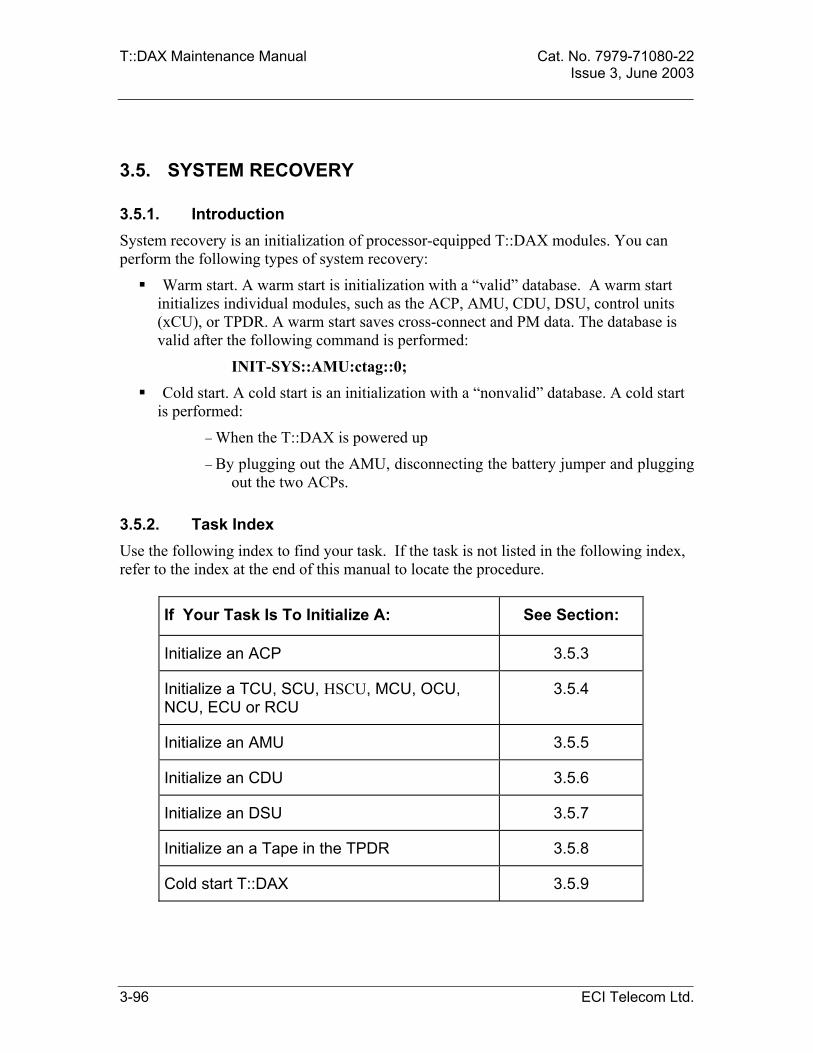
T::DAX Maintenance Manual Cat. No. 7979-71080-22 Issue 3, June 2003
3.5.
3.5.1. Introduction
3.5.2.
SYSTEM RECOVERY
System recovery is an initialization of processor-equipped T::DAX modules. You can perform the following types of system recovery:
Warm start. A warm start is initialization with a “valid” database. A warm start initializes individual modules, such as the ACP, AMU, CDU, DSU, control units (xCU), or TPDR. A warm start saves cross-connect and PM data. The database is valid after the following command is performed:
INIT-SYS::AMU:ctag::0;
Cold start. A cold start is an initialization with a “nonvalid” database. A cold start is performed:
− When the T::DAX is powered up
− By plugging out the AMU, disconnecting the battery jumper and plugging out the two ACPs.
Task Index Use the following index to find your task. If the task is not listed in the following index, refer to the index at the end of this manual to locate the procedure.
If Your Task Is To Initialize A: See Section:
Initialize an ACP 3.5.3
Initialize a TCU, SCU, HSCU, MCU, OCU, NCU, ECU or RCU
3.5.4
Initialize an AMU 3.5.5
Initialize an CDU 3.5.6
Initialize an DSU 3.5.7
Initialize an a Tape in the TPDR 3.5.8
Cold start T::DAX 3.5.9
3-96 ECI Telecom Ltd.

Cat. No. 7979-71080-22 T::DAX Maintenance Manual Issue 3, June 2003 3.5.3. Initialize a ACP ACP initialization is a recovery task that resets the ACP/TACP/PACP/HACP to a normal software and hardware state. Use the following procedure to initialize an ACP. The active or standby ACP can be initialized.
Step Initializing an ACP
1 To initialize the ACP, enter:
INIT-SYS:[tid]:ACP-n:ctag::0:RUSURE=rusure;
n = A or B, whichever ACP is being initialized. If the active ACP is initialized it will cause a switch to standby. rusure – enter Y to initialize the processor unconditionally.
Example response (for an active ACP):
TDAX 02-01-06 17:16:16
A 001 REPT INITZN
"ACP-A:ACTIVITY=ACT,REASON=STARTOFINIT,INITMD=SOFT,DBVALID=YES"
;
<
TDAX 02-01-06 17:22:26
A 002 REPT INITZN
"ACP-B:ACTIVITY=ACT,REASON=ENDOFINIT,INITMD=SOFT,DBVALID=YES"
2 To verify that a ACP has been initialized, enter:
RTRV-COND-EQPT:[tid]:ACP-n:ctag;
n = A or B.
ECI Telecom Ltd. 3-97

T::DAX Maintenance Manual Cat. No. 7979-71080-22 Issue 3, June 2003
3.5.4. Initialize a Control Unit (xCU) Control unit processor initialization is a recovery task that resets the module processor to a normal software and hardware state. Use the following procedure to initialize a TCU, SCU, HSCU, MCU, OCU or RCU.
Step Initializing a Control Unit
1 To initialize the control unit enter:
INIT-SYS:[tid]:aid:ctag::0:RUSURE=rusure;
0 - is the degree or level of initialization (zero).
rusure – enter Y to initialize the processor unconditionally This is required to initiate the active unit. If an active unit is initialized it will become standby.
2 To verify that the processor has been initialized, enter:
RTRV-COND-EQPT:[tid]:aid:ctag;
3-98 ECI Telecom Ltd.

Cat. No. 7979-71080-22 T::DAX Maintenance Manual Issue 3, June 2003
3.5.5. Initialize an AMU AMU initialization is a recovery task that writes a signature sequence of bytes to the AMU/TAMU/HAMU module, allowing the system database to be restored from the AMU during future ACP initializations. Note: After an ACP initialization with no valid database on the AMU, the AMU remains in the out-of-service state and cannot be written to until this command is issued for the AMU. This is required on initial system turn up, and when the AMU is replaced. Use the following procedure to initialize an AMU.
Step Initializing an AMU
1 To initialize the AMU enter:
INIT-SYS:[tid]:AMU:ctag::0;
0 - initialization level (zero).
2 To verify that a AMU has been initialized, enter:
RTRV-COND-EQPT:[tid]:AMU:ctag;
Example response: M BRUN RTRV "AMU,EQPT:TYPEREP=IS" /*1 records retrieved*/
3 Retrieve the memory status of the AMU to verify the PCU program status on the AMU.
RTRV-MEMSTAT-EQPT::AMU:ctag;
Example response: ctag RTRV /* 0 record retrieved*/
If there are no records, as shown, the PCU programs should be downloaded from the DSU as follows:
STA-LOCL-RST::ctag; CPY-MEM::FROMMEM=SEC, TOMEM=WKG:ctag::PGM:Rel=x.xx; There will be two flashes of the "OOS" and "ACT" LEDs on the standby ACP. Then both ACP "OOS" LEDs will go on. After about 20 seconds the "OOS" LED on the ACP that is standby will go out. The active ACP "OOS" LED will stay on until the initialization is completed. After a completed initialization the "ACT" LED will turn on. This takes about 3 minutes for a basic system, 6 minutes for a double capacity system and 12 minutes for quad capacity system.
ECI Telecom Ltd. 3-99

T::DAX Maintenance Manual Cat. No. 7979-71080-22 Issue 3, June 2003
3.5.6. Initialize a CDU CDU initialization is a recovery task that initializes the timing reference algorithm that locks to the timing reference. Use the following procedure to initialize a CDU.
Step Initializing a CDU
1 To initialize the CDU enter:
INIT-SYS:[tid]:aid:ctag::1;
2 To verify that an CDU has been initialized, enter:
RTRV-COND-EQPT:[tid]:aid:ctag;
Example response:
M [ctag] RTRV
“CDU,EQPT:TYPEREP=IS”
3 To retrieve the CDU boot program version, enter:
RTRV-MEMSTAT-EQPT::aid:ctag;
3-100 ECI Telecom Ltd.

Cat. No. 7979-71080-22 T::DAX Maintenance Manual Issue 3, June 2003
3.5.7. Initialize a DSU DSU initialization is a recovery task that formats the disk.
Step Initializing a DSU
1 The DSU must be removed from service to initialize.
RMV-EQPT:[tid]:DSU:ctag::FRCD;
2 To initialize the DSU enter:
INIT-SYS:[tid]:DSU:ctag::0:[RUSURE=Y];
3 Restore the DSU to service.
RST-EQPT:[tid]:DSU:ctag;
4 To verify that an DSU has been initialized, enter:
RTRV-COND-EQPT:[tid]:DSU:ctag;
Example response: M BRUN RTRV
"DSU,EQPT:TYPEREP=IS"
/*1 records retrieved*/
5 Upload the system program and database to the DSU as per the procedure in section 3.4.18.
ECI Telecom Ltd. 3-101

T::DAX Maintenance Manual Cat. No. 7979-71080-22 Issue 3, June 2003
3.5.8. Initialize a Tape Tape initialization is a recovery task that erases the tape and it is necessary to remove the TPDR and the DSU by command first. Use the following procedure to initialize a tape in the TPDR.
Step Initializing a Tape in the TPDR
1 To initialize the TPDR enter:
RMV-EQPT:[tid]:TPDR:ctag::FRCD;
The DSU must also be removed to initialize the tape.
RMV-EQPT::DSU:ctag::FRCD;
2 Insert the tape to the TPDR.
To initialize the Tape enter:
INIT-SYS:[tid]:TPDR:ctag::0:[RUSURE=Y]; Restore the TPDR and DSU to service.
3 Restore service to the TPDR and the DSU. Enter:
RST-EQPT::DSU&TPDR:ctag;
4 To verify that a tape in the TPDR has been initialized, enter:
RTRV-COND-EQPT:[tid]:TPDR:ctag; The system will report that it cannot find the file if the tape has not initialized.
The tape has now been initialized and formatted. As part of a memory task the database should be loaded back onto the tape as per section 3.3.4.
3-102 ECI Telecom Ltd.

Cat. No. 7979-71080-22 T::DAX Maintenance Manual Issue 3, June 2003
3.5.9. Cold Start T::DAX If a fatal error occurs and there is no other way to correct it, perform the following procedures to cold-start T::DAX.
Step Initiating a Cold Start
1 If possible, log off T::DAX. (connect to the CIT port)
2 Plug out the standby ACP, active ACP and AMU units.
3 Disconnect the battery jumper on the AMU.
4 Plug in ACP-A, wait for the log in message on the CIT terminal and AMU units.
Connect the AMU battery jumper and plug in the AMU and log into the T::DAX.
5 Plug in ACP-B and refer to installation and turn-up procedures to provision the T::DAX from startup.
ECI Telecom Ltd. 3-103


Cat. No. 7979-71080-22 T::DAX Maintenance Manual Issue 3, June 2003
APPENDIX A - T::DAX ERROR CODES
If T::DAX denies a requested action, it responds with an error code. The error code provides a general description of the reason for denial. T::DAX may also report additional information with the error code. Refer to the following alphabetical list of error codes for recommended corrective action. For additional information, contact your system administrator. EATN Equipage, not valid for access type. The requested test access mode requires that
the tested port be connected.
EFON Equipage, feature option not provided. The standby ACP cannot diagnose or initialize any equipment other than itself.
ENAT Equipage, request not valid for access type. Not currently used.
ENEQ Equipage, not equipped - The specified entity is not installed and/or is not recognized by T::DAX as physically present. Contact your system administrator for additional information.
ENPM Equipage, not equipped for performance monitoring. Not currently used.
ENPS Equipage, not equipped with protection switching - Verify you entered the correct aid. If incorrect, re-enter command with correct aid. If correct, aid is not available. Check module status with on-site maintenance personnel.
ENRI Equipage, not equipped for retrieving specified information. User requested undefined information, such as data for a PCU in RTRV-MEMSTAT.
EQWT Equipage, wrong type - The specified equipment is the wrong type. Re-enter the command using the correct equipment type.
IBEX Input, block extra - The number of parameter blocks entered in the input command is more than required. Re-enter command using correct number of parameter blocks. (Refer to Appendix B, Operation and Administration Manual for command format).
IBMS Input, block missing - The number of parameter blocks entered in the input command is less than required. Re-enter command using correct number of parameter blocks. (Refer to Appendix B, Operation and Administration Manual for command format).
IBNC Input, block not consistent. Void or unnamed parameters were entered in a name-defined block.
ECI Telecom Ltd. A-1

T::DAX Maintenance Manual Cat. No. 7979-71080-22 Issue 3, June 2003
ICNC Input, command not consistent - The valid command verb is mutually exclusive
with a valid modifier or the two valid modifiers are mutually exclusive with each other. Re-enter the command using correct verb and modifiers. (Refer to Appendix B, Operation and Administration Manual, for command format).
ICNV Input, command not valid - The command verb or first or second modifier is invalid. Re-enter command using correct command verb and/or modifiers. (Refer to Appendix B, Operation and Administration Manual, for command format).
IDNC Input, data not consistent. Value of one parameter is inconsistent with value of another parameter.
IDNV Input, data not valid - A simple or compound parameter entered in the input command is invalid. Re-enter command using correct data. (Refer to Appendix B, Operation and Administration Manual, for command format).
IDRG Input, data range error - A parameter value entered in the input command is inconsistent with its defined type or falls outside its allowable range. Re-enter command using data within allowable range and of a consistent type. (Refer to Appendix B, Operation and Administration Manual, for range limits).
IIAC Input, invalid access identifier. AID is that of a protection unit when a working unit AID is required.
IISP Input, invalid syntax or punctuation - Re-enter command using correct syntax. (Refer to Appendix B for command syntax).
IITA Input, invalid target identifier - Re-enter command using correct target identifier (TID). (Refer to circuit records for correct TID).
INUP Input, non-null unimplemented parameter. Type, aol, pst and sst may not be entered for a DS1/E1 tributary.
IPEX Input, parameter extra - A valid parameter is illegally used or repeated. Re-enter command using correct number of parameters. (Refer to Appendix B, Operation and Administration Manual, for command format.)
IPMS Input, parameter missing - A required parameter is missing from the input command. Re-enter command using correct number of parameters. (Refer to Appendix B, Operation and Administration Manual, for command format).
IPNV Input, parameter not valid - A parameter name in the input command was not valid. Re-enter command using correct parameter names. (Refer to Appendix B, Operation and Administration Manual, for command format).
MERR Multiple error - More than one error condition exists. Re-enter command using correct format. (Refer to Appendix B, Operation and Administration Manual, for command format).
PICC Privilege, illegal command code - The command code is not allowed with the stated password, operations channel, or data terminal in use. Enter another command or contact your system administrator for additional information.
A-2 ECI Telecom Ltd.

Cat. No. 7979-71080-22 T::DAX Maintenance Manual Issue 3, June 2003 PIPW Privilege, illegal password - You entered the incorrect password and/or user
identification code. Enter the correct password and/or user identification code.
RABY Resource, all test access ports busy - Repeat test access request later.
RCBY Resource, circuit busy. Maximum number of test accesses supported by the hardware has been reached.
RTBY Resource, requested TAP busy. The requested TAP is not available.
SAAL Status, already allowed - Entity is already in allowed state; no action required.
SAAS Status, already assigned - Entity has already been assigned; no action required.
SABT Status, aborted. Command was aborted due to user request or ACP shutdown.
SAIN Status, already inhibited - Entity has already been inhibited; no action required.
SAIS Status, already in service - Entity is already in service; no action required.
SAMS Status, already in maintenance state - Entity is already in maintenance state; no action required.
SAOP Status, already operated - Entity is already operated; no action required.
SAPS Status, already in protection state - Entity is already in protection state; no action required.
SARB Status, all resources busy - The system is busy or overloaded. No input command can be accepted or executed. Repeat request later.
SATF Status, automatic test failed - automatic diagnostic test failed when restoring unit to service. Repeat restoration command. If failure occurs again, replace unit.
SAWS Status, already in working state - Entity is already in working state; no action required.
SCNA Status, command not able to be aborted. Command was not aborted an ABT-CMD request failed, probably because aborting is not supported by the command in question.
SCNF Status, command not found. No command with the given cmdctag in an ABT-CMD request was found.
SDNC Status, data not consistent - A piece of input data is not consistent with a piece of data stored in the T::DAX database. Re-enter input command with correct data.
SEAE Status, supported entity attributes entered - The entity is currently supporting other entities that have active attributes.
SIPE Status, internal program error. Should never occur.
SLEM Status, list exceed maximum. Retrieval query too complex - too many parameter groups. Use of the && operator instead of & where possible may improve the situation.
SNCN Status, NE unable to execute command. Not currently used.
ECI Telecom Ltd. A-3
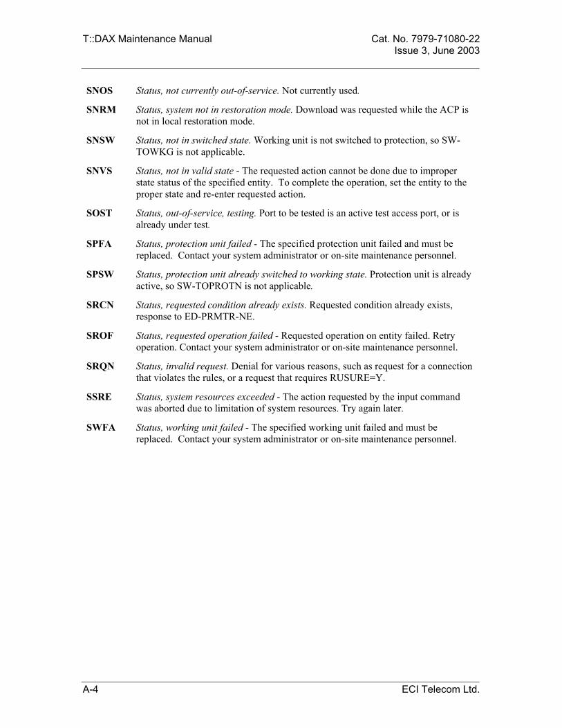
T::DAX Maintenance Manual Cat. No. 7979-71080-22 Issue 3, June 2003
SNOS Status, not currently out-of-service. Not currently used.
SNRM Status, system not in restoration mode. Download was requested while the ACP is not in local restoration mode.
SNSW Status, not in switched state. Working unit is not switched to protection, so SW-TOWKG is not applicable.
SNVS Status, not in valid state - The requested action cannot be done due to improper state status of the specified entity. To complete the operation, set the entity to the proper state and re-enter requested action.
SOST Status, out-of-service, testing. Port to be tested is an active test access port, or is already under test.
SPFA Status, protection unit failed - The specified protection unit failed and must be replaced. Contact your system administrator or on-site maintenance personnel.
SPSW Status, protection unit already switched to working state. Protection unit is already active, so SW-TOPROTN is not applicable.
SRCN Status, requested condition already exists. Requested condition already exists, response to ED-PRMTR-NE.
SROF Status, requested operation failed - Requested operation on entity failed. Retry operation. Contact your system administrator or on-site maintenance personnel.
SRQN Status, invalid request. Denial for various reasons, such as request for a connection that violates the rules, or a request that requires RUSURE=Y.
SSRE Status, system resources exceeded - The action requested by the input command was aborted due to limitation of system resources. Try again later.
SWFA Status, working unit failed - The specified working unit failed and must be replaced. Contact your system administrator or on-site maintenance personnel.
A-4 ECI Telecom Ltd.