62971711 Getting Started With PDMS
100
Getting Started With PDMS
description
PDMS Getting Started
Transcript of 62971711 Getting Started With PDMS

Getting Started
With PDMS

DisclaimerInformation of a technical nature, and particulars of the product and its use, is given by AVEVASolutions Ltd and its subsidiaries without warranty. AVEVA Solutions Ltd and its subsidiaries disclaimany and all warranties and conditions, expressed or implied, to the fullest extent permitted by law.
Neither the author nor AVEVA Solutions Ltd, or any of its subsidiaries, shall be liable to any person orentity for any actions, claims, loss or damage arising from the use or possession of any information,particulars, or errors in this publication, or any incorrect use of the product, whatsoever.
CopyrightCopyright and all other intellectual property rights in this manual and the associated software, and everypart of it (including source code, object code, any data contained in it, the manual and any otherdocumentation supplied with it) belongs to AVEVA Solutions Ltd or its subsidiaries.
All other rights are reserved to AVEVA Solutions Ltd and its subsidiaries. The information contained inthis document is commercially sensitive, and shall not be copied, reproduced, stored in a retrievalsystem, or transmitted without the prior written permission of AVEVA Solutions Ltd. Where suchpermission is granted, it expressly requires that this Disclaimer and Copyright notice is prominentlydisplayed at the beginning of every copy that is made.
The manual and associated documentation may not be adapted, reproduced, or copied, in any materialor electronic form, without the prior written permission of AVEVA Solutions Ltd. The user may also notreverse engineer, decompile, copy, or adapt the associated software. Neither the whole, nor part of theproduct described in this publication may be incorporated into any third-party software, product,machine, or system without the prior written permission of AVEVA Solutions Ltd, save as permitted bylaw. Any such unauthorised action is strictly prohibited, and may give rise to civil liabilities and criminalprosecution.
The AVEVA products described in this guide are to be installed and operated strictly in accordance withthe terms and conditions of the respective licence agreements, and in accordance with the relevantUser Documentation. Unauthorised or unlicensed use of the product is strictly prohibited.
First published September 2007
© AVEVA Solutions Ltd, and its subsidiaries
AVEVA Solutions Ltd, High Cross, Madingley Road, Cambridge, CB3 0HB, United Kingdom
TrademarksAVEVA and Tribon are registered trademarks of AVEVA Solutions Ltd or its subsidiaries. Unauthoriseduse of the AVEVA or Tribon trademarks is strictly forbidden.
AVEVA product names are trademarks or registered trademarks of AVEVA Solutions Ltd or itssubsidiaries, registered in the UK, Europe and other countries (worldwide).
The copyright, trade mark rights, or other intellectual property rights in any other product, its name orlogo belongs to its respective owner.
AVEVA Solutions Ltd

Getting Started With PDMS
Contents Page
Getting Started With PDMS
Getting StartedScope of this Manual . . . . . . . . . . . . . . . . . . . . . . . . . . . . . . . . . . . . . 1:1What it Includes . . . . . . . . . . . . . . . . . . . . . . . . . . . . . . . . . . . . . . . . . . . . . . . . . . . 1:1Who Should Use this Manual . . . . . . . . . . . . . . . . . . . . . . . . . . . . . . . . . . . . . . . . 1:1Assumptions. . . . . . . . . . . . . . . . . . . . . . . . . . . . . . . . . . . . . . . . . . . . . . . . . . . . . . . . . . . . . 1:1
How the Manual is Organised . . . . . . . . . . . . . . . . . . . . . . . . . . . . . . . . . . . . . . . . 1:2
PDMS Functions . . . . . . . . . . . . . . . . . . . . . . . . . . . . . . . . . . . . . . . . . 2:1Using PDMS in the PlantDesign Process . . . . . . . . . . . . . . . . . . . . . . . . . . . . . . 2:2PDMS Modules . . . . . . . . . . . . . . . . . . . . . . . . . . . . . . . . . . . . . . . . . . . . . . . . . . . . 2:3DESIGN Modules . . . . . . . . . . . . . . . . . . . . . . . . . . . . . . . . . . . . . . . . . . . . . . . . . . . . . . . . . 2:3Drafting Modules . . . . . . . . . . . . . . . . . . . . . . . . . . . . . . . . . . . . . . . . . . . . . . . . . . . . . . . . . 2:4Catalogue and Specification Management Modules . . . . . . . . . . . . . . . . . . . . . . . . . . . . . . 2:6Project Administration Modules . . . . . . . . . . . . . . . . . . . . . . . . . . . . . . . . . . . . . . . . . . . . . . 2:7
PDMS Databases. . . . . . . . . . . . . . . . . . . . . . . . . . . . . . . . . . . . . . . . . 3:1Introduction . . . . . . . . . . . . . . . . . . . . . . . . . . . . . . . . . . . . . . . . . . . . . . . . . . . . . . 3:1Database Types . . . . . . . . . . . . . . . . . . . . . . . . . . . . . . . . . . . . . . . . . . . . . . . . . . . 3:1Project . . . . . . . . . . . . . . . . . . . . . . . . . . . . . . . . . . . . . . . . . . . . . . . . . . . . . . . . . . . . . . 3:1DESIGN Database . . . . . . . . . . . . . . . . . . . . . . . . . . . . . . . . . . . . . . . . . . . . . . . . . . . . . . . . 3:2PADD Database. . . . . . . . . . . . . . . . . . . . . . . . . . . . . . . . . . . . . . . . . . . . . . . . . . . . . . . . . . 3:2ISOD Database . . . . . . . . . . . . . . . . . . . . . . . . . . . . . . . . . . . . . . . . . . . . . . . . . . . . . . . . . . 3:2CATALOGUE Database. . . . . . . . . . . . . . . . . . . . . . . . . . . . . . . . . . . . . . . . . . . . . . . . . . . . 3:2DICTIONARY Database. . . . . . . . . . . . . . . . . . . . . . . . . . . . . . . . . . . . . . . . . . . . . . . . . . . . 3:3PROPERTIES Database . . . . . . . . . . . . . . . . . . . . . . . . . . . . . . . . . . . . . . . . . . . . . . . . . . . 3:3
12.0i

Getting Started With PDMS
SYSTEM Database . . . . . . . . . . . . . . . . . . . . . . . . . . . . . . . . . . . . . . . . . . . . . . . . . . . . . . . 3:3COMMS Database . . . . . . . . . . . . . . . . . . . . . . . . . . . . . . . . . . . . . . . . . . . . . . . . . . . . . . . . 3:3MISC Database . . . . . . . . . . . . . . . . . . . . . . . . . . . . . . . . . . . . . . . . . . . . . . . . . . . . . . . . . . 3:3TRANSACTION Database . . . . . . . . . . . . . . . . . . . . . . . . . . . . . . . . . . . . . . . . . . . . . . . . . . 3:4
How PDMS Data is Stored . . . . . . . . . . . . . . . . . . . . . . . . . . . . . . . . . 4:1DESIGN Database Element Types . . . . . . . . . . . . . . . . . . . . . . . . . . . . . . . . . . . . 4:2WORLD . . . . . . . . . . . . . . . . . . . . . . . . . . . . . . . . . . . . . . . . . . . . . . . . . . . . . . . . . . . . . . 4:2SITE . . . . . . . . . . . . . . . . . . . . . . . . . . . . . . . . . . . . . . . . . . . . . . . . . . . . . . . . . . . . . . 4:2ZONE . . . . . . . . . . . . . . . . . . . . . . . . . . . . . . . . . . . . . . . . . . . . . . . . . . . . . . . . . . . . . . 4:2EQUIPMENT (EQUI) . . . . . . . . . . . . . . . . . . . . . . . . . . . . . . . . . . . . . . . . . . . . . . . . . . . . . . 4:2SUB-EQUIPMENT (SUBE) . . . . . . . . . . . . . . . . . . . . . . . . . . . . . . . . . . . . . . . . . . . . . . . . . 4:3PRIMITIVES. . . . . . . . . . . . . . . . . . . . . . . . . . . . . . . . . . . . . . . . . . . . . . . . . . . . . . . . . . . . . 4:4STRUCTURES (STRU) . . . . . . . . . . . . . . . . . . . . . . . . . . . . . . . . . . . . . . . . . . . . . . . . . . . . 4:4FRAMEWORK (FRMW). . . . . . . . . . . . . . . . . . . . . . . . . . . . . . . . . . . . . . . . . . . . . . . . . . . . 4:4SUB-FRAMEWORK (SBFR) . . . . . . . . . . . . . . . . . . . . . . . . . . . . . . . . . . . . . . . . . . . . . . . . 4:5STRUCTURAL COMPONENTS . . . . . . . . . . . . . . . . . . . . . . . . . . . . . . . . . . . . . . . . . . . . . 4:5PIPE . . . . . . . . . . . . . . . . . . . . . . . . . . . . . . . . . . . . . . . . . . . . . . . . . . . . . . . . . . . . . . 4:5BRANCH (BRAN). . . . . . . . . . . . . . . . . . . . . . . . . . . . . . . . . . . . . . . . . . . . . . . . . . . . . . . . . 4:6PIPING COMPONENTS . . . . . . . . . . . . . . . . . . . . . . . . . . . . . . . . . . . . . . . . . . . . . . . . . . . 4:6
Attributes in PDMS. . . . . . . . . . . . . . . . . . . . . . . . . . . . . . . . . . . . . . . . . . . . . . . . . 4:7NAME . . . . . . . . . . . . . . . . . . . . . . . . . . . . . . . . . . . . . . . . . . . . . . . . . . . . . . . . . . . . . . 4:8TYPE . . . . . . . . . . . . . . . . . . . . . . . . . . . . . . . . . . . . . . . . . . . . . . . . . . . . . . . . . . . . . . 4:9LOCK . . . . . . . . . . . . . . . . . . . . . . . . . . . . . . . . . . . . . . . . . . . . . . . . . . . . . . . . . . . . . . 4:9OWNER . . . . . . . . . . . . . . . . . . . . . . . . . . . . . . . . . . . . . . . . . . . . . . . . . . . . . . . . . . . . . . 4:9POSITION . . . . . . . . . . . . . . . . . . . . . . . . . . . . . . . . . . . . . . . . . . . . . . . . . . . . . . . . . . . . . 4:10ORIENTATION. . . . . . . . . . . . . . . . . . . . . . . . . . . . . . . . . . . . . . . . . . . . . . . . . . . . . . . . . . 4:11LEVEL . . . . . . . . . . . . . . . . . . . . . . . . . . . . . . . . . . . . . . . . . . . . . . . . . . . . . . . . . . . . . 4:11OBSTRUCTION . . . . . . . . . . . . . . . . . . . . . . . . . . . . . . . . . . . . . . . . . . . . . . . . . . . . . . . . . 4:11HEIGHT . . . . . . . . . . . . . . . . . . . . . . . . . . . . . . . . . . . . . . . . . . . . . . . . . . . . . . . . . . . . . 4:12DIAMETER. . . . . . . . . . . . . . . . . . . . . . . . . . . . . . . . . . . . . . . . . . . . . . . . . . . . . . . . . . . . . 4:12
UDAs (User Defined Attributes) . . . . . . . . . . . . . . . . . . . . . . . . . . . . . . . . . . . . . 4:12Pseudo-Attributes . . . . . . . . . . . . . . . . . . . . . . . . . . . . . . . . . . . . . . . . . . . . . . . . 4:12Attributes Form . . . . . . . . . . . . . . . . . . . . . . . . . . . . . . . . . . . . . . . . . . . . . . . . . . 4:12
Using PDMS. . . . . . . . . . . . . . . . . . . . . . . . . . . . . . . . . . . . . . . . . . . . . 5:1Logging into PDMS . . . . . . . . . . . . . . . . . . . . . . . . . . . . . . . . . . . . . . . . . . . . . . . . 5:1Project . . . . . . . . . . . . . . . . . . . . . . . . . . . . . . . . . . . . . . . . . . . . . . . . . . . . . . . . . . . . . . 5:1Username . . . . . . . . . . . . . . . . . . . . . . . . . . . . . . . . . . . . . . . . . . . . . . . . . . . . . . . . . . . . . . 5:2
12.0ii

Getting Started With PDMS
Password . . . . . . . . . . . . . . . . . . . . . . . . . . . . . . . . . . . . . . . . . . . . . . . . . . . . . . . . . . . . . . 5:3MDB . . . . . . . . . . . . . . . . . . . . . . . . . . . . . . . . . . . . . . . . . . . . . . . . . . . . . . . . . . . . . . 5:3Module . . . . . . . . . . . . . . . . . . . . . . . . . . . . . . . . . . . . . . . . . . . . . . . . . . . . . . . . . . . . . . 5:4Read Only . . . . . . . . . . . . . . . . . . . . . . . . . . . . . . . . . . . . . . . . . . . . . . . . . . . . . . . . . . . . . . 5:5Restore Views . . . . . . . . . . . . . . . . . . . . . . . . . . . . . . . . . . . . . . . . . . . . . . . . . . . . . . . . . . . 5:5
Exit out of PDMS . . . . . . . . . . . . . . . . . . . . . . . . . . . . . . . . . . . . . . . . . . . . . . . . . . 5:5Internationalisation . . . . . . . . . . . . . . . . . . . . . . . . . . . . . . . . . . . . . . . . . . . . . . . . 5:6Customisation Facilities; The Programmable Macro Language (PML). . . . . . . 5:7
Basic GUI Features . . . . . . . . . . . . . . . . . . . . . . . . . . . . . . . . . . . . . . . 6:1Using the Mouse . . . . . . . . . . . . . . . . . . . . . . . . . . . . . . . . . . . . . . . . . . . . . . . . . . 6:1Using Forms . . . . . . . . . . . . . . . . . . . . . . . . . . . . . . . . . . . . . . . . . . . . . . . . . . . . . . 6:1Text Boxes . . . . . . . . . . . . . . . . . . . . . . . . . . . . . . . . . . . . . . . . . . . . . . . . . . . . . . . . . . . . . . 6:2Drop-down Lists . . . . . . . . . . . . . . . . . . . . . . . . . . . . . . . . . . . . . . . . . . . . . . . . . . . . . . . . . . 6:2Option Buttons . . . . . . . . . . . . . . . . . . . . . . . . . . . . . . . . . . . . . . . . . . . . . . . . . . . . . . . . . . . 6:2Check Boxes . . . . . . . . . . . . . . . . . . . . . . . . . . . . . . . . . . . . . . . . . . . . . . . . . . . . . . . . . . . . 6:3Scrollable Lists . . . . . . . . . . . . . . . . . . . . . . . . . . . . . . . . . . . . . . . . . . . . . . . . . . . . . . . . . . . 6:3Action Buttons . . . . . . . . . . . . . . . . . . . . . . . . . . . . . . . . . . . . . . . . . . . . . . . . . . . . . . . . . . . 6:3
Menus . . . . . . . . . . . . . . . . . . . . . . . . . . . . . . . . . . . . . . . . . . . . . . . . . . . . . . . . 6:4Toolbars . . . . . . . . . . . . . . . . . . . . . . . . . . . . . . . . . . . . . . . . . . . . . . . . . . . . . . . . 6:4Status Bar . . . . . . . . . . . . . . . . . . . . . . . . . . . . . . . . . . . . . . . . . . . . . . . . . . . . . . . . 6:5Respond to Alert Forms . . . . . . . . . . . . . . . . . . . . . . . . . . . . . . . . . . . . . . . . . . . . 6:5Dockable Forms, Toolbars and Menu Bars . . . . . . . . . . . . . . . . . . . . . . . . . . . . . 6:5Toolbars . . . . . . . . . . . . . . . . . . . . . . . . . . . . . . . . . . . . . . . . . . . . . . . . . . . . . . . . . . . . . . 6:5Menu Bars . . . . . . . . . . . . . . . . . . . . . . . . . . . . . . . . . . . . . . . . . . . . . . . . . . . . . . . . . . . . . . 6:6Forms . . . . . . . . . . . . . . . . . . . . . . . . . . . . . . . . . . . . . . . . . . . . . . . . . . . . . . . . . . . . . . 6:6
Using Commands. . . . . . . . . . . . . . . . . . . . . . . . . . . . . . . . . . . . . . . . . . . . . . . . . 6:10Why use Command Syntax? . . . . . . . . . . . . . . . . . . . . . . . . . . . . . . . . . . . . . . . . . . . . . . . 6:10Command Window. . . . . . . . . . . . . . . . . . . . . . . . . . . . . . . . . . . . . . . . . . . . . . . . . . . . . . . 6:10Note on Filenames . . . . . . . . . . . . . . . . . . . . . . . . . . . . . . . . . . . . . . . . . . . . . . . . . . . . . . . 6:11
Basic Operations in PDMS . . . . . . . . . . . . . . . . . . . . . . . . . . . . . . . . . 7:1Querying . . . . . . . . . . . . . . . . . . . . . . . . . . . . . . . . . . . . . . . . . . . . . . . . . . . . . . . . 7:1Current Element and Current List Position . . . . . . . . . . . . . . . . . . . . . . . . . . . . . 7:2Navigate to a Given Element. . . . . . . . . . . . . . . . . . . . . . . . . . . . . . . . . . . . . . . . . 7:3Design Explorer . . . . . . . . . . . . . . . . . . . . . . . . . . . . . . . . . . . . . . . . . . . . . . . . . . . . . . . . . . 7:4Members List . . . . . . . . . . . . . . . . . . . . . . . . . . . . . . . . . . . . . . . . . . . . . . . . . . . . . . . . . . . . 7:5
12.0iii

Getting Started With PDMS
Other Explorers . . . . . . . . . . . . . . . . . . . . . . . . . . . . . . . . . . . . . . . . . . . . . . . . . . . . . . . . . . 7:6My Data . . . . . . . . . . . . . . . . . . . . . . . . . . . . . . . . . . . . . . . . . . . . . . . . . . . . . . . . . . . . . . 7:6
Modify the Content of a Database . . . . . . . . . . . . . . . . . . . . . . . . . . . . . . . . . . . . 7:7Drawlist GUI . . . . . . . . . . . . . . . . . . . . . . . . . . . . . . . . . . . . . . . . . . . . . . . . . . . . . . 7:7Change the Visual Properties. . . . . . . . . . . . . . . . . . . . . . . . . . . . . . . . . . . . . . . . . . . . . . . . 7:9Display of Graphical Selection . . . . . . . . . . . . . . . . . . . . . . . . . . . . . . . . . . . . . . . . . . . . . . 7:10Display of Primitives . . . . . . . . . . . . . . . . . . . . . . . . . . . . . . . . . . . . . . . . . . . . . . . . . . . . . . 7:10Other Drawlist Functions . . . . . . . . . . . . . . . . . . . . . . . . . . . . . . . . . . . . . . . . . . . . . . . . . . 7:10
PDMS Search Utility. . . . . . . . . . . . . . . . . . . . . . . . . . . . . . . . . . . . . . . . . . . . . . . 7:13Saved Searches. . . . . . . . . . . . . . . . . . . . . . . . . . . . . . . . . . . . . . . . . . . . . . . . . . . . . . . . . 7:17Create a Saved Search . . . . . . . . . . . . . . . . . . . . . . . . . . . . . . . . . . . . . . . . . . . . . . . . . . . 7:17Delete a Saved Search . . . . . . . . . . . . . . . . . . . . . . . . . . . . . . . . . . . . . . . . . . . . . . . . . . . 7:17Explorer Bar Functionality . . . . . . . . . . . . . . . . . . . . . . . . . . . . . . . . . . . . . . . . . . . . . . . . . 7:17Search Results . . . . . . . . . . . . . . . . . . . . . . . . . . . . . . . . . . . . . . . . . . . . . . . . . . . . . . . . . . 7:17Functionality on the Search Output Form. . . . . . . . . . . . . . . . . . . . . . . . . . . . . . . . . . . . . . 7:19
GUI Grid Data . . . . . . . . . . . . . . . . . . . . . . . . . . . . . . . . . . . . . . . . . . . . . . . . . . . . 7:20Move around the Grid using the Keyboard. . . . . . . . . . . . . . . . . . . . . . . . . . . . . . . . . . . . . 7:21Selection . . . . . . . . . . . . . . . . . . . . . . . . . . . . . . . . . . . . . . . . . . . . . . . . . . . . . . . . . . . . . 7:21Grid Splitting. . . . . . . . . . . . . . . . . . . . . . . . . . . . . . . . . . . . . . . . . . . . . . . . . . . . . . . . . . . . 7:23Pin Rows and Columns . . . . . . . . . . . . . . . . . . . . . . . . . . . . . . . . . . . . . . . . . . . . . . . . . . . 7:24Row and Column Size . . . . . . . . . . . . . . . . . . . . . . . . . . . . . . . . . . . . . . . . . . . . . . . . . . . . 7:24Column Re-order . . . . . . . . . . . . . . . . . . . . . . . . . . . . . . . . . . . . . . . . . . . . . . . . . . . . . . . . 7:25Column Sort . . . . . . . . . . . . . . . . . . . . . . . . . . . . . . . . . . . . . . . . . . . . . . . . . . . . . . . . . . . . 7:25Column Filter . . . . . . . . . . . . . . . . . . . . . . . . . . . . . . . . . . . . . . . . . . . . . . . . . . . . . . . . . . . 7:25Numeric Data Functions. . . . . . . . . . . . . . . . . . . . . . . . . . . . . . . . . . . . . . . . . . . . . . . . . . . 7:27Group Sorting . . . . . . . . . . . . . . . . . . . . . . . . . . . . . . . . . . . . . . . . . . . . . . . . . . . . . . . . . . . 7:27Miscellaneous Grid Data Functions . . . . . . . . . . . . . . . . . . . . . . . . . . . . . . . . . . . . . . . . . . 7:29
Product Range. . . . . . . . . . . . . . . . . . . . . . . . . . . . . . . . . . . . . . . . . . . 8:1Introduction . . . . . . . . . . . . . . . . . . . . . . . . . . . . . . . . . . . . . . . . . . . . . . . . . . . . . . 8:1Products . . . . . . . . . . . . . . . . . . . . . . . . . . . . . . . . . . . . . . . . . . . . . . . . . . . . . . . . . . . . . . 8:1
Glossary of Terms and Abbreviations . . . . . . . . . . . . . . . . . . . . . . . 9:1Introduction . . . . . . . . . . . . . . . . . . . . . . . . . . . . . . . . . . . . . . . . . . . . . . . . . . . . . . 9:1Definitions. . . . . . . . . . . . . . . . . . . . . . . . . . . . . . . . . . . . . . . . . . . . . . . . . . . . . . . . 9:1Abbreviations and Acronyms . . . . . . . . . . . . . . . . . . . . . . . . . . . . . . . . . . . . . . . . 9:5
12.0iv

Getting Started With PDMSScope of this Manual
1 Scope of this Manual
1.1 What it IncludesThis manual provides an introduction to PDMS as a system and describes some functionswhich are common to several disciplines. The manual gives an introduction to what PDMSdoes and how it does it, including introductions to:
• the PDMS modules and what they do• the PDMS databases• the PDMS user interface.
More detailed information, particularly on the PDMS modules and the databases they use,can be found elsewhere in the PDMS user documentation set.
1.2 Who Should Use this ManualThe manual is written for a new user who is:
• coming to a 3D Plant Design Management System (i.e. PDMS) for the first time
or• migrating from a similar 3D system.
Both types of user will probably, but not necessarily, have attended a PDMS Basic Trainingcourse.
1.2.1 AssumptionsIt is assumed that the user:
• is familiar with Microsoft Windows 2000 and/or XP• has a reasonable understanding of the principles and jargon of process plant design.
12.01:1

Getting Started With PDMSScope of this Manual
1.3 How the Manual is OrganisedThe manual is organised as follows:
PDMS Functions introduces the basic steps to be taken to design a Plantusing PDMS, and introduces the PDMS modules.
PDMS Databases andHow PDMS Data isStored
introduce the PDMS databases and the way data in PDMSis structured and how it is stored.
Using PDMS, Basic GUIFeatures and BasicOperations in PDMS
describe how to get in to PDMS and use it perform simpleoperations.
Product Range shows the AVEVA product ranges.
Glossary of Terms andAbbreviations
is a glossary of PDMS terms and abbreviations.
12.01:2

Getting Started With PDMSPDMS Functions
2 PDMS Functions
PDMS (the Plant Design Management System) enables you to design a 3D computer modelof a process plant. PDMS allows you to see a full colour-shaded representation of theplantmodel as your design progresses, adding an extremely impressive level of realism totraditional drawing office techniques.
In the model you can store huge amounts of data referring to position, size, part numbersand geometric relationships for the various parts of the plant. This model becomes a singlesource of engineering data for all of the sections and disciplines involved in a design project.
All this information is stored in databases. There are many different output channels fromthe databases through which information can be passed on. These range from reports ondata stored in the databases, fully annotated and dimensioned engineering drawings, to fullcolour-shaded 3D walk-through capabilities which allow you to visualise the completedesign model.
Even with the advanced features of PDMS, the main form of communication between theplant designer and the fabricator remains the drawings. Without engineering drawings thetask of building a plant would be almost impossible. To meet this requirement, PDMS can
12.02:1

Getting Started With PDMSPDMS Functions
produce numerous types of drawing, ranging from complex 3D illustrations to fullyannotated and dimensioned arrangement drawings and piping isometrics.
All the data in a PDMS design would be of little value without the ability to ensure the qualityof the design information. PDMS contributes to the quality of the design in the followingways:
• Ensures consistent and reliable component dataIn a design environment which uses only 2D drawing techniques, the size of eachfitting must be decided before it can be drawn. This is a time-consuming and error-prone process, where often the design errors are only found during the erection stageof the project. With PDMS, all piping component sizes and geometry are predefinedand stored in a catalogue, which cannot be changed by the designer. This ensuresthat all items are true to size and are consistent throughout the design, no matter howmany users there are on the project.
• Adheres to definable engineering specificationsPiping specifications and steelwork catalogues, stating precisely the components to beused, are compiled for the purpose of ensuring consistent, safe and economic design.Design applications for Piping, Hangers and Supports, HVAC, Cable trays andSteelwork all use specifications to assist component selection.
• Ensures correct geometry and connectivityThere are many different ways of making design errors, such as incorrect fittinglengths, incompatible flange ratings, or simple alignment errors. PDMS can check all ofthese using data consistency procedures built into the system to check all or individualparts of the design model.
• Avoids component interferencesDespite a wealth of skill and experience in plantdesign, traditional drawing officetechniques are still subject to human error. Laying out complex pipe runs and generalarrangements in confined areas using conventional 2D methods, inevitably leads toclashes between elements, which are trying to share the same physical space. PDMSenables you to avoid such problems in two ways:
1. By viewing the design interactively during the design process, allowing visualchecks on the model from different viewpoints. Potential problems can thus beresolved as they arise.
2. By using the powerful clash checking facility within PDMS, which will detect clashesanywhere in the plant. This can be done interactively or retrospectively.
• Annotation and dimensions obtained directly from the design databaseExtracted information from the PDMS database, such as arrangement drawings, pipingisometrics and reports, will always be the latest available as it is stored only in onesource. Through the course of a project, information is constantly changing anddrawings need to be reissued. When this happens, drawings, reports etc can beupdated and reissued with the minimum of effort.
2.1 Using PDMS in the PlantDesign ProcessThe sequence of operations (greatly simplified) in a new plant design project would be:
• Create the project and set up administrative controls (using the PDMS ADMINmodule).
• Create the Catalogue and Specification data from which standard design Componentscan be selected (using the PARAGON module).
• Design the various parts of the plant, referencing items from the catalogues (using theDESIGN module).
• Check the design for errors and inconsistencies (DESIGN module).
12.02:2

Getting Started With PDMSPDMS Functions
• Document the design in the form of drawings (general arrangement, construction,assembly, and isometric), reports and material lists (DRAFT and ISODRAFT modules).
You may also wish to transfer design data to or from other systems at various stages.
2.2 PDMS ModulesPDMS is split into a number of modules which are used at different stages in the plantdesign process.
2.2.1 DESIGN Modules
DESIGN
DESIGN is the main, graphically driven constructor module. It enables a full sized three-dimensional plantmodel to be defined in the design database, with selected views of thecurrent state of the design shown on the graphics screen as the design progresses.
All parts of the design (including equipment, and piping and structural steelwork layouts) canbe created. Component selection is provided through Specifications that dictate whichCatalogue Components can be used. Each part of the design model can be displayed incolour-shaded ‘solid’ colour-coded representations for ease of interpretation.
The DESIGN module can check for interferences (clashes) between items created in thedesign. There is a very flexible reporting capability that can be used to produce a widevariety of design documents - from bulk Material Take Off to detailed nozzle schedules.
Piping isometrics can be previewed in DESIGN (without having to switch to the Isometricdrawing generation module, ISODRAFT).
12.02:3

Getting Started With PDMSPDMS Functions
SPOOLER
SPOOLER is used for pipework spooling. It allows the designer to split the pipework designinto logical sections (spools) ready for fabrication. The spool data can then be output asisometric drawings using ISODRAFT (see below).
2.2.2 Drafting Modules
DRAFT
DRAFT enables dimensioned and annotated scale drawings of selected parts of the designmodel to be produced. All information needed to create the drawing is accessible via asingle drawing database, which extracts data to be used for dimensioning directly from theDESIGN database.
Annotation can be in the form of labels attached to DESIGN elements, or 2D annotationsuch as drawing notes, or drawing frames, tables, lines etc.
Annotation attached to a design data element on the drawing will move if the 3D position ofthe element changes. Dimensions are recalculated automatically every time the drawing isupdated.
A design model 3D view can be previewed in DRAFT to aid assembly of a drawing in the 2Dview.
12.02:4

Getting Started With PDMSPDMS Functions
Diagrams
Diagrams supports the creation of cabling diagrams. The application is based on the AVEVADesign Platform GUI and diagram layouts are created using an embedded Microsoft OfficeVisio drawing control. All relevant data entered through the application is stored into theSchematic Database.
ISODRAFT
ISODRAFT produces automatically annotated and dimensioned piping isometric drawings,with associated material lists, of specified sections of the plant pipework. The content andstyle of the drawings can be chosen to suit the needs of pipe fabricators and/or erectors andcan include a wide range of optional features to suit local requirements.
Other facilities include:• Full material lists.• Automatic spool identification.• Automatic splitting of complex drawings.• User-defined drawing sheets.
12.02:5

Getting Started With PDMSPDMS Functions
2.2.3 Catalogue and Specification Management Modules
PARAGON
Used to generate and modify catalogues, with facilities for catalogue componentconstruction with visual control (including 3D colour-shaded representations of the itembeing designed). The catalogues in PDMS serve a similar purpose to the manufacturers’catalogues, which you would refer to when using conventional design methods. The PDMScomponent catalogue is used to specify the geometry, connection information, obstructionand detailing data of steelwork, piping, and HVAC and cable tray components.
It should be noted that, whereas the design data is specific to a particular design,catalogues and specifications may be specific to a company but general to a number ofprojects in that company. For example, the same catalogue component may also appear inother designs proceeding at the same time.
SPECON
Used by the administrator to create or modify the component specifications within thecatalogue database. Specifications define the suitability of catalogue components forparticular types of use.
PROPCON
Used by the administrator to create or modify the properties database, which holds detailsof those properties of the components and materials which may be needed for stressanalysis or safety auditing of all or part of a design. It also includes data such as the material
12.02:6

Getting Started With PDMSPDMS Functions
densities needed by the DESIGN module structural applications for calculating weights andcentre of gravity of steelwork items.
2.2.4 Project Administration Modules
ADMIN
Large plants designed using PDMS will usually be broken down into individual areas (eitherphysical areas or design areas), depending on the physical size, complexity andconfiguration of the plant. On a large project, the System Administrator will first agree withProject and Design Management, the breakdown of the PDMS project into sections which:
• Are relevant to the needs of project reporting and control.• Form reasonable design subdivisions with sensible match-lines and design content.• Enable enough designers to work in parallel with simultaneous access to carry out their
design tasks.
In much the same way as in a design office (with its section leader, draftspeople, etc.),PDMS has Teams, the members of which are called Users. These Teams can consist ofany number of Users and can be organised by discipline or physical work areas.
The main features are:• Access Control (Teams and Users)• Databases• Multiple Databases (MDBs)• Database management functionality
ADMIN includes a database integrity checking utility, used to check for inconsistencies inthe contents of the databases and to derive statistical information about the use of thedatabase storage capacity.
ADMIN also allows the System Administrator to reconfigure a project. This may benecessary:
• to compact databases at intervals, freeing disk space • to upgrade PDMS projects when the database structure changes• to compare the contents of two similar databases; for example, to create a modification
record
LEXICON
Used by the System Administrator to set up user defined attributes (UDA) and user defineddefined element types (UDET). Both are defined in a DICTIONARY database. User definedelement types allow objects in a database to be given a user defined name to replace thegeneric name, for example an EQUI element can be called a :PUMP or :VESSEL. Additionalinformation can be stored in user defined attributes assigned to database elements andextracted into drawings and reports.
MONITOR Module
The MONITOR Module is commonly used to query the status of a projects users and accessrights. MONITOR allows basic querying of database information which normally can only beobtained using the ADMIN Module (which can only be accessed by a Free user).
MONITOR can also be used to quickly change a password of the currently logged in user orcompletely switch to another user (if the user credentials are known).
12.02:7

Getting Started With PDMSPDMS Functions
Depending on the user type (Free or General), MONITOR can be used to change accessrights and defer databases.
Batch processing and simply messaging can also be achieved.
If there is a problem with a project that inhibits another PDMS module from loading, then thesoftware will automatically load the MONITOR Module allowing simple diagnostics to beconducted via its command line interface.
For a detailed explanation of the MONITOR Module refer to MONITOR Reference Manual.
12.02:8

Getting Started With PDMSPDMS Databases
3 PDMS Databases
3.1 IntroductionThe overall purpose of PDMS is the controlled creation of a complete three-dimensionalprocess plant design model using computer-simulation techniques. All information whichexists about a PDMS design project, whether administrative or technical, is stored in aseries of hierarchical databases. Use of the various PDMS modules allows you to create,modify and extract information from these databases.
This chapter describes• The purpose of each type of database• How the detailed project information is held in each• How the separate databases are related to each other
3.2 Database Types
3.2.1 ProjectA PDMS Project consists of the complete collection of information which relates to a singledesign project. This is identified by a name, allocated by the Project Administrator when theproject is first initiated. This name is used to identify the project to the system whenever youwish to work in the project using PDMS. This allows access rights and use of systemresources to be monitored and controlled. For further details of these functions, see theAdministrator User Guide and Monitor Reference Manuals.
There are 10 different types of database which can go to make up a complete Project:
Design and Drawing Databases:• DESIGN database• PADD (DRAFT) database• ISOD (Spooler) database
Reference Databases:• CATALOGUE database• LEXICON (Dictionary)• PROPERTIES database
Administration Databases:• SYSTEM database• COMMS database
12.03:1

Getting Started With PDMSPDMS Databases
• MISC database• TRANSACTION database
(Refer to the Administrator User Guide for more background information on Referencedatabases).
Each PDMS module requires access to one or more specific database types, and entry tothe module may be prevented if appropriate databases do not exist or if you don’t have theappropriate access rights. New databases can only be created by the ProjectAdministrator; see the Administrator User Guide for details.
The functions of each type of database are summarised in the following subsections.
3.2.2 DESIGN DatabaseThe DESIGN databases contain all information needed to create a full-scale three-dimensional representation of the plant.
Each user is normally allowed to modify the DESIGN databases which relate to his functionin the plant design team, and will often have permission to look at other DESIGN databasesso that his work is compatible with that of other designers.
Typical design functions, each of which may use a different DESIGN database, include:• Equipment design (process vessels, storage vessels, pumps, heat exchangers etc.)• Pipework design (the interconnecting pipes between the various equipment items)• Structural design (the columns, beams, walls, stairways etc. which support and give
access to the operational equipment and pipework)• Hangers and Supports (specialised pipe support structures)
The compositions of the principal types of DESIGN element are described in the Data ModelReference Manual.
3.2.3 PADD DatabaseThe Production of Annotated and Dimensioned Drawings (PADD) database holds dataabout both the pictorial content of drawings and about their annotation and dimensionalinformation. It therefore holds a complete specification of the contents of a drawing. Its useis specific to the interactive drawing module DRAFT.
For further information, see the Draft User Guide.
3.2.4 ISOD DatabaseThe ISOD database holds pipework spool drawings generated by the SPOOLER module.See Pipework Design User Guide for more details of SPOOLER.
3.2.5 CATALOGUE DatabaseThe CATALOGUE database contains a catalogue of the standard components which theuser may select when designing pipework, ducting, hangers and supports or structuralsteelwork. It includes:
• Dimensional details for each component• Details of permissible connections between different components and of the bolts
needed to assemble flanged components
12.03:2

Getting Started With PDMSPDMS Databases
• Specifications of the components, which define the conditions of use for each type(maximum pressure, temperature etc.)
A CATALOGUE database may contain a single ‘universal’ catalogue, but it will morecommonly contain a general catalogue plus one or more specialised catalogues specific toparticular design functions. For further information, see the Catalogues and SpecificationsUser Guide.
3.2.6 DICTIONARY DatabaseThe DICTIONARY database holds the definitions of user defined attributes (UDA) and userdefined element types (UDET). User defined elements types allow objects in a database tobe given a user defined name to replace the generic name, for example an EQUI elementcan be called a :PUMP or :VESSEL. Additional information can be stored in user definedattributes assigned to database elements and extracted into drawings and reports.
3.2.7 PROPERTIES DatabaseThe PROPERTIES is available for storing data about material properties, which may beneeded to supplement Catalogue and Specification data for some design functions such asstress analysis. Its use is specialised and will not be described further in this manual.
For further information, see the PROPCON chapter in the Catalogues and SpecificationsReference Manual.
3.2.8 SYSTEM DatabaseThere is only one SYSTEM database in each Project Folder. It holds administrativeinformation about the composition and use of the project, including the following:
• A list of databases of all categories which are usable in the project• A list of all users, identified by name and password, who can legally access the
databases, and the operating team(s) to which they are assigned• A list of PDMS modules available for use in the project• Access control data, which defines those databases which are accessible to any
specific user and whether he may modify them or only look at them
3.2.9 COMMS DatabaseThe COMMS database stores the information about who is using which module and whichdatabases are current. Each user has a separate area of the COMMS database, which canbe accessed in write mode, and so can record module changes etc. Each user has readaccess to the other users’ areas, and so can find out about other users in the project.
3.2.10 MISC DatabaseThe MISC database is used to store inter-user messages, and inter-database macros. Thisdatabase can only be opened in write mode by one user at a time, but many users can readfrom it. All users need to be able to write to this database, but only when they are sendingmessages or writing inter-database macros, or deleting messages and macros. All userscan read from the database at any time.
12.03:3

Getting Started With PDMSPDMS Databases
3.2.11 TRANSACTION DatabaseTo enable the System Administrator to monitor the progress of Global commands, PDMSGlobal stores details of issued commands in a TRANSACTION database. Transactionmessages are generated in the database each time the progress of the command changes.
Transaction databases are only present when PDMS incorporates the Global product. SeeAdmininstrator Command Reference Manual for details of Global.
12.03:4

Getting Started With PDMSHow PDMS Data is Stored
4 How PDMS Data is Stored
Despite the huge power and potential of PDMS, the database is structured in a very simpleand logical form. The database is hierarchical, a tree like structure, as illustrated below.
Note: The hierarchy below illustrates the (simplified) DESIGN database hierarchy, but theCATALOGUE, PADD, ISOD, LEXICON and PROPERTIES databases also have ahierarchical structure.
In this hierarchical structure all the database elements are owned by other elements, withthe exception of the WORLD. Elements that are owned by another element, e.g. a ZONE is
12.04:1

Getting Started With PDMSHow PDMS Data is Stored
owned by a SITE, are said to be members of the owning element, e.g. The ZONE is amember of the SITE.
4.1 DESIGN Database Element Types
4.1.1 WORLDWhen the database is first built, it is empty except for a single element named the WORLD.Every database has its own WORLD element as the first element in the hierarchy.
4.1.2 SITEBelow the WORLD, the second level of the hierarchy is the SITE. A SITE may beconsidered as a significant collection of plant, whose size is not necessarily determined byphysical area, but by practical considerations. It may, for example be the whole project, orone part of a large project. There can be as many SITEs within a PDMS project as requiredfor data organisation.
4.1.3 ZONEThe next level below a SITE is a ZONE. Again, a ZONE is not necessarily used to define aphysical area, it is more likely to store similar types of item for easy reference, such as apiping system in one ZONE, related equipment in another, and so on. There can be as manyZONEs owned by a site as required for data organisation.
Below ZONE level the hierarchy is discipline dependent, i.e. the elements depend on whichdiscipline you are modelling.
4.1.4 EQUIPMENT (EQUI)Equipment items are built up in PDMS using elements known as primitives. Each piece ofEquipment can comprise any number of primitive shapes positioned to form the item. Theprimitives may be owned directly by the EQUI element or by a Sub-Equipment element. AnEquipment would typically be a Pump, or a Vessel. The Box and Cylinder primitives areclearly visible in the Pump Equipment shown in figure below.
12.04:2

Getting Started With PDMSHow PDMS Data is Stored
4.1.5 SUB-EQUIPMENT (SUBE)A SUBE is an optional element to further sub-divide an EQUI. The SUBE can also ownprimitive elements.
12.04:3

Getting Started With PDMSHow PDMS Data is Stored
4.1.6 PRIMITIVESPrimitives are the basic building blocks of PDMS. They are used by other disciplines tocreate catalogue components. There are many types of primitive, each with its ownfeatures, which when combined with other primitives can represent complex shapes.Examples of primitives are nozzle (NOZZ), box (BOX), cylinders (CYLI) and pyramids(PYRA).
4.1.7 STRUCTURES (STRU)STRU elements are administrative elements, i.e. they exist to own FRAMEWORK elements,and allow the plant structures to be separated for ease of modelling and reporting.
4.1.8 FRAMEWORK (FRMW)FRMW elements are used to store structural components in the model. A complex structurecan be divided into logical frameworks. Dividing the structure in this way allows structuralmodelling, and also reporting, to be done more efficiently, e.g. by copying a completeFRMW. Structural components may also be owned by a Sub-Framework element.
12.04:4

Getting Started With PDMSHow PDMS Data is Stored
4.1.9 SUB-FRAMEWORK (SBFR)A SBFR is an optional element that can own structural components. Subframeworks areused to further sub-divide complex projects or for modelling sub-assemblies within aframework.
4.1.10 STRUCTURAL COMPONENTSStructural profiles are represented in PDMS by section (SCTN) elements. I-section profilesizes are selected using a Section Specification that references standard catalogue datafor section sizes complying with various national standards. Plates are represented by panel(PANE) elements and curved profiles are modelled using a general section (GENSEC)component.
4.1.11 PIPEPipes may be considered like lines on a flowsheet. They may run between several endconnection points and are usually grouped by a common specification and process.
12.04:5

Getting Started With PDMSHow PDMS Data is Stored
4.1.12 BRANCH (BRAN)Branch elements are sections of a pipe, which have known start and finish points. In PDMSthe start and finish points are called the Head and Tail. Heads and tails may be connectedto nozzles, tees or other Heads and tails, depending on the configuration of the pipe, or leftopen ended.
4.1.13 PIPING COMPONENTS A BRAN can own a wide variety of components such as gaskets (GASK), flanges (FLAN),tees (TEE), valves (VALV), elbows (ELBO), etc. These form the shape and geometry of theBRAN and ultimately the pipeline itself.
Piping components are selected using Piping Specifications that reference standardcatalogue data. For example, each time you want to use a 100mm bore elbow, PDMSalways accesses the data for it from the component catalogue. The data for this remainsconstant no matter how many 100mm bore elbows are used in the design.
12.04:6

Getting Started With PDMSHow PDMS Data is Stored
4.2 Attributes in PDMSEvery element in a PDMS database has a fixed set of properties known as its attributes.Some attributes are common throughout the range of elements while others differ accordingto the type of element involved. For example, a cylinder (CYLI) has HEIGHT andDIAMETER attributes whilst the size of a box (BOX) is determined by XLENGTH, YLENGTHand ZLENGTH attributes, as illustrated below:
12.04:7

Getting Started With PDMSHow PDMS Data is Stored
When you create an element, a set of appropriate attributes are entered into the database.The attributes will vary according to the type of element but essentially the process is thesame. For example, a cylinder has the following attributes:
4.2.1 NAMEEvery element in PDMS can be named. Whether named or not every element will have aunique system-generated reference number. If a name is not specified, then a hierarchydescription will be displayed in the Design Explorer or Members List (see Navigate to aGiven Element). Internally PDMS uses the reference number since this cannot change. Atable of names against reference numbers is maintained for this purpose.
Attribute Default Value
NAME Name if specified or hierarchy description
TYPE CYLI
LOCK false (the element is not locked)
OWNER the name of the owning element or its hierarchy description
POSITION N 0mm E 0mm U 0mm (relative to its owner)
ORIENTATION Y is N and Z is U (relative to its owner)
LEVEL 0 10 (this is a representation level setting)
OBSTRUCTION 2 (it is a solid hard element for clashing purposes)
DIAMETER 0 mm
HEIGHT 0 mm
12.04:8

Getting Started With PDMSHow PDMS Data is Stored
All PDMS names begin with a forward slash character (/), which is considered to be part ofthe name. In order to save you the effort of typing this, all of the forms you encounter willadd the forward slash for you when you press the Enter key after typing a name. Theforward slash character is not shown in the Design Explorer or Members List. The WORLDhas a special name in PDMS, /*.
Names cannot contain spaces and are case sensitive. For example, /E1302A is a differentname from /E1302a or /e1302A. Elements in a PDMS database are unique, i.e. they cannothave the same name or reference number.
4.2.2 TYPEThis attribute refers to the specific type of element it is, e.g. EQUI is an Equipment type.
4.2.3 LOCKThe LOCK attribute determines if an element may be changed or not. If an element islocked, its LOCK attribute is set to the value TRUE, preventing it from being modified untilunlocked. By default, LOCK is false.
4.2.4 OWNERThe different levels in the hierarchy are maintained by an Owner-Member relationship. AnEQUI will have ZONE as its owner, while a CYLI might well be one of the EQUI’s members.The owner is that element which is directly related to the current element at the next level upin the hierarchy, as shown in the diagram below:
12.04:9

Getting Started With PDMSHow PDMS Data is Stored
The element on the upper level is the Owner of those elements directly below it, e.g. theequipment (EQUI) owns the primitive (CYLI). The lower level elements are Members of theowning element, e.g. the EQUI is a member of the ZONE.
4.2.5 POSITIONMany items in a database have a POSITION attribute which is the position of the element inrelation to its owner. All primitives have a position attribute which relates to its point of origin.As each primitive has a different Point of Origin changing the position attribute will have theeffect of moving the cylinder to some other position with its point of origin positioned on thenew co-ordinates.
12.04:10

Getting Started With PDMSHow PDMS Data is Stored
4.2.6 ORIENTATIONBy default, a cylinder is created in a vertical direction; that is, with one of its ends facing up.The orientation attribute allows this to be changed to any angle on any axis.
4.2.7 LEVELPDMS can produce different representations of an item, depending on how it has beenmodelled and the representation levels used. The default level is 0 to 10 but levels can beset beyond this range if needed.
For example, steelwork profiles can be represented by centreline (stick representation) onlyor by the full detail of the section profile. By manipulating level settings it is, therefore,possible to have simple or complex representation of elements for DESIGN display orDRAFT drawings.
4.2.8 OBSTRUCTIONThe OBSTRUCTION attribute is used to declare whether an element is solid or not.Obstructions can be declared as Hard, Soft or No Obstruction, depending on the value ofthe OBSTRUCTION attribute. The default value of 2 results in a Hard obstruction, 1 resultsin a Soft obstruction (used for walkways, maintenance access etc.) and 0 is for NoObstruction (used to save computing time when elements are enclosed in another elementwhich acts as an overall obstruction).
12.04:11

Getting Started With PDMSHow PDMS Data is Stored
4.2.9 HEIGHTThe height of the cylinder.
4.2.10 DIAMETERThe diameter of the cylinder.
4.3 UDAs (User Defined Attributes)This type of attribute is defined and assigned to elements using the LEXICON module bythe System or Project Administrator. A UDA is just like any other attribute but may bespecific to the company or the particular project. The setting of the UDA is up to the user,although it may have been set to a default value. Changing this is the same as with all otherattributes. Their current values may be found by querying the items attributes. A UDA canbe recognised by the colon placed in front of it:
4.4 Pseudo-AttributesThese are attributes that are set by the system for a specific purpose, and cannot bechanged by the user.
4.5 Attributes FormThe Attributes Form displays all the attributes that have been specified for a databaseelement. The form is accessed by selecting Display>Attributes Utility from the Designmain menu bar:
:COLOUR (User Defined Attribute)
:HEIGHT (Normal Attribute)
12.04:12

Getting Started With PDMSHow PDMS Data is Stored
The left hand column shows the names of the attributes, the right hand column shows thevalues. A brief description of the attribute is provided at the bottom of the form.
All data in the form is read-only; it is not possible to add or delete attributes, or to changetheir values.
Invisible attributes are not shown on the form (these are set by the system or ProjectAdministrator using the LEXICON module).
Attributes are grouped according to the categorisations; these are also set in LEXICON. Theform above shows three attribute categorisations: Construction, General and Misc. If anattribute does not have a categorisation, then it is assigned an appropriate draftcategorisation in the Attribute Form.
The form can be docked, floating and resized.
Icons at the top of the form determine how the attributes are listed:
12.04:13

Getting Started With PDMSHow PDMS Data is Stored
When the left icon is selected, the attributes are grouped by Category or by Data Type, asdetermined by selecting the appropriate options from the right-click menu (describedbelow).
When the middle icon is selected, all the attributes are listed alphabetically, regardless ofCategory or Data Type.
Right-clicking anywhere on the form displays a pop-up menu with the following options:
Track CE - By default the form will track the current element. That is, if the current elementis changed in the Design Explorer or 3D View, the form’s content will change to display theattributes of the new current element. This menu option toggles tracking on or off.
Groups by Category - The attributes are grouped according to Category (which are set inLEXICON). The Category icon at the top of the form also needs to be selected.
Group by Data Type - The attributes are grouped according to their data type, i.e. Boolean,Double, Element, Hyperlink, Integer, Orientation, Position, String and Word. The Data Typeicon also needs to be selected.
Show Description - Used to hide/show the description field at the bottom of the form.
Collapse All Nodes - Collapses all nodes in the list - equivalent to clicking on all the ‘-’icons on the left hand side of the form.
Expand All Nodes - Expands all nodes in the list - equivalent to clicking on all the ‘+’ iconson the left hand side of the form.
Open Document - For an attribute of data type ‘hyperlink’, the pathname of a referenceddocument will be displayed in the Value field. Selecting this option opens the referenceddocument. It will be opened outside PDMS; PDMS does not control access rights to thedocument.
Array attributes are shown with each member of the array listed separately, using a spaceas the separator, as shown in the following example:
12.04:14

Getting Started With PDMSHow PDMS Data is Stored
12.04:15

Getting Started With PDMSHow PDMS Data is Stored
12.04:16

Getting Started With PDMSUsing PDMS
5 Using PDMS
5.1 Logging into PDMSAssuming PDMS has been correctly installed on your workstation, start PDMS by selectingStart>Programs>AVEVA>Plant 12.0>Run Plant; two command windows and a ‘splashscreen’ will appear briefly. The Login form that appears requires you to specify a number ofdetails at the outset of your session.
To enter PDMS, you must first click on the Login form to make it active. The form should bepopulated in the following order.
5.1.1 ProjectIn the Project field enter a three letter project code. Alternatively a long project identifier canbe entered if one has been created by the System Administrator.
Clicking on to the right of the field will open the following PDMS Projects form.
12.05:1

Getting Started With PDMSUsing PDMS
This form lists all available PDMS Projects.
Clicking on the Sort by pull down allows the sorting of the list of available projects. Thefollowing selections can be made.
• Project• Project Code• Name• Description
A filter may also be applied to the list of available projects by entering a criteria in the Filterfield; an asterisk may be used as a wildcard.
Note: The Filter field only applies to the Project column of the list of available projects.
Clicking on a project will result in the PDMS Projects form closing and the selected projectwill be populated in the Project field of the Login form.
5.1.2 UsernameA username will have been allocated to you by the System Administrator.
Clicking on to the right of the Username field will open the Select User form.
12.05:2

Getting Started With PDMSUsing PDMS
Click on the Sort by pull down allows the sorting of the list of available users in a project.The following selections can be made.
• Name• Description
A filter may also be applied to the list of available projects by entering a criteria in the Filterfield; an asterisk may be used as a wildcard.
Note: The Filter field only applies to the Name column of the list of available users.
Clicking on a user will result in the Select User form closing and the selected user will bepopulated in the Username field of the Login form.
5.1.3 PasswordA password will have been allocated to you by the System Administrator. Passwords arecase sensitive, be sure to enter correctly.
Clicking on the Change button to the right of the password field will allow the user to changethe password for the selected user. You will be prompted to enter a new password and toconfirm the change.
5.1.4 MDBNote: Before attempting to enter a value for the MDB field make sure that a valid username
and password has been entered. You will not be able to proceed if not the case.
In the MDB field enter the name of a Multiple Database you wish to use.
Clicking on to the right of the field will open the Select MDB form.
12.05:3

Getting Started With PDMSUsing PDMS
Clicking on the Sort by pull down allows the sorting of the lists of available MultipleDatabases.
The following selections can be made:• Name• Description
A filter may also be applied to the list of available projects by entering a criteria in the Filterfield; an asterisk may be used as a wildcard.
Note: The Filter field only applies to the Name column of the list of available MDBs.
Clicking on a MDB will result in the Select MDB form closing and the selected MDB will bepopulated in the MDB field of the Login form.
5.1.5 ModuleFrom this pull down select the PDMS Module to launch, the following options are available.
• MONITOR• DESIGN• DIAGRAMS• SPOOLER• DRAFT• ISODRAFT• PARAGON• SPECON• PROPCON• LEXICON• ADMIN
12.05:4

Getting Started With PDMSUsing PDMS
5.1.6 Read OnlyTo modify the database as you work, leave the Read Only check box unchecked. Onlyselect this option to view the project in the Read Only mode.
Click on the OK button to enter the selected module.
5.1.7 Restore ViewsThis Restore views check box is only available when DRAFT is selected in the Module pull-down.
Restore views effectively restores the layout of all forms and re-opens the last known projectat the point where it was left when the Draft application was exited from a previous session.
If the Restore views box is checked then the following will take place immediately when theDraft module is loaded:
• Re-position all forms to the locations they were left in the last open session.• Automatically conduct a Get Work operation.• Position the current element in the Draft Explorer to the selected element in the last
session.
5.2 Exit out of PDMSYou will normally leave PDMS directly from the application module in which you are working.You may either save all work done in the current module before leaving or you may quitdirectly without updating any databases.
Select Design>Exit:
All the modules have an Exit menu selection; the one shown below being for DESIGN:
If you have made changes prior to selecting Exit and have not carried out a SAVEWORKoperation, you will be asked if you first wish to save your changes to the appropriatedatabase:
Clicking YES at this point would be the equivalent of doing a SAVEWORK (and then aQUIT). If you have done a SAVEWORK (and made no subsequent changes), or if you havemade no changes at all during your Design session, then Exit will display a message askingyou to confirm that you wish to leave DESIGN:
12.05:5

Getting Started With PDMSUsing PDMS
In every case, when you leave PDMS you will be returned to the operating system at thepoint from which you entered PDMS.
5.3 InternationalisationMicrosoft produces many localised variants of Windows. AVEVA products are designed towork in English on all of these, though they do not currently support the use of all the locallanguages. At the time of writing, AVEVA provides limited facilities that vary somewhatbetween products.
Users of PDMS need to enter data (text and names) using their local language and outputthe same onto deliverables such as drawings, reports etc. In some cases, there is also aneed to localise or translate the user interface. The same data are also required in otherproducts such as AVEVA Plant Design Review.
By default, your PDMS project can use any language whose characters are contained withinthe Latin-1 character set, comprising:
PDMS can also support the following groups of languages:
Far Eastern, comprising:
Latin-2, comprising:
Danish Dutch English Faroese
Finnish French Icelandic Irish
Spanish German Norwegian Portuguese
Swedish Italian
Japanese Simplified Chinese
Korean Traditional Chinese
Albanian Czech English German
Hungarian Polish Rumanian
Serbo-Croatian Slovak Slovene
12.05:6

Getting Started With PDMSUsing PDMS
Latin-Cyrillic, comprising:
PDMS does not support any other character set/language, nor does it support the mixing ofany of the above except the mixing of one Far Eastern language with English.
PDMS must know if you are using a non-Latin-1 language in order to display characterscorrectly on drawings.
To use an alternative character set/language:• You must use an appropriate version of Windows and a suitable keyboard.
• You must select the appropriate options from the Windows , RegionalOptions.
For further details, see the Plant Installation Guide, also the Administrator User Guide fordetails of font families.
5.4 Customisation Facilities; The Programmable Macro Language (PML)Most PDMS modules make use of a Graphical User Interface (GUI) to drive the software.The interfaces provided with PDMS are designed to apply to a wide range of situations andbusiness needs. However, as you become more experienced with PDMS you may wish todesign an interface which is more closely related to your requirements. You do this usingAVEVA’s Programmable Macro Language (PML).
For full details of PML, refer to the Software Customisation Guide and the SoftwareCustomisation Reference Manual.
Before you begin customising a GUI, you must have a good working knowledge of thecommand syntax for the module you are working with. The commands are described indetail in the reference manuals for the modules.
The ability to customise individual Applications to suit your own specific needs gives yougreat flexibility in the ways in which you use your system. But it also introduces the risk thatyour modified macros may not be compatible with future versions of the software, since theyare no longer under AVEVA’s control. Your own Applications may diverge from futurestandard versions and may not take advantage of product enhancements incorporated intothe standard product. To minimise this risk, it is most important that your in-housecustomisation policies constrain any changes which you make to the Applications so thatthey retain maximum compatibility with the standard product at all times. Remember thatAVEVA can give you full technical support only for products over which it has control. Itcannot guarantee to solve problems caused by software which you have written yourself.
Bulgarian Byelorussian English
Macedonian Serbo-Croatian Ukrainian Russian
12.05:7

Getting Started With PDMSUsing PDMS
12.05:8

Getting Started With PDMSBasic GUI Features
6 Basic GUI Features
PDMS uses a Graphical User Interface (GUI) using forms (dialogue boxes) and menuswith which Microsoft Windows users should be familiar. This chapter describes those GUIfeatures which are specific to PDMS.
6.1 Using the MouseYou use the mouse to steer the pointer around the screen and to select or pick items byusing the mouse buttons. The buttons perform different tasks depending on the type ofwindow, and the position within the window, where the pointer is positioned. Theappearance of the pointer changes according to the type of display item that is underneathit.
The left-hand mouse button has three functions:• On a graphical view, clicking the left-hand button with the pointer over a design element
results in that element becoming the current element (that is, the design item on whichyou want to carry out the next operation).
• In a sequence of menus, dragging with the left-hand button activates the commandrepresented by the highlighted menu option when the button is released.
• On a form, the effect varies according to what you select.
The middle mouse button is used primarily to manipulate a graphical view. The right-handbutton is used to access the menu options specific to the graphical view window, or itemslisted on a form.
6.2 Using FormsForms are used both to display information and to let you enter new data. Forms typicallycomprise an arrangement of buttons of various types, text-boxes, and scrollable lists. Inputto a form is usually via a combination of mouse and keyboard.
While you have access to a form, you can change a setting, return to the initial values,accept and act on the current data, or cancel the form without applying any changes,according to the nature of the form.
Forms can include any of the following:• text boxes• drop-down lists• option buttons• check boxes• scrollable lists
12.06:1

Getting Started With PDMSBasic GUI Features
• action buttons.
6.2.1 Text Boxes
Text boxes are the areas where you type in alphanumeric data such as names ordimensions. A text box will usually have a label to tell you what to enter.
When you first open a form which contains text boxes, the first text-box on the form iscurrent and a text editing cursor (a vertical bar) is displayed in the box. A text-box oftencontains a default entry (such as ‘unset’) when first displayed. Some text boxes accept onlytext or only numeric data, and entries with the wrong type of data are not accepted.
To enter data into a text box:• Click in the box to insert the text editing cursor.• Type in the required data, editing any existing entry as necessary. (You may need to
delete the existing entry first.)• When you have finished, confirm the entry by pressing the Enter (or Return) key. Any
text box with an unconfirmed setting is highlighted by a yellow background.
6.2.2 Drop-down ListsDrop-down lists let you choose one option from a multiple selection. The list will usuallyhave a label to tell you what you are setting and will show the current selection.
They typically have the following appearance:
To change the setting, click on the down arrow or button face to reveal the full list ofavailable options, then pick the required option.
6.2.3 Option ButtonsOption buttons are used to select one option, from a group of options. The selection ismutually exclusive, so that selecting one option deselects others in that group automatically.
They typically have the following appearance:
To change the selected option button in a group, click the required button.
Option selected
Option not selected
12.06:2

Getting Started With PDMSBasic GUI Features
6.2.4 Check BoxesCheck boxes are used to switch an option between two states, typically set and unset.Unlike option buttons, they do not interact, so that you can set any combination of checkboxes at the same time.
They typically have the following appearance:
6.2.5 Scrollable Lists
A scrollable list is displayed as a vertical list of options within a form, with vertical andhorizontal scroll bars along its sides. To select an option, click on the line you want. Theselected line is highlighted.
Some scrollable lists let you make only a single selection, so that selecting any optiondeselects all others automatically. Other lists let you make multiple selections, with allselected options highlighted simultaneously. You can deselect a highlighted option in amultiple-choice list, by clicking on it again (repeated clicks toggle a selection).
6.2.6 Action ButtonsMost forms include one or more action buttons. You use these to tell PDMS what to do withthe details you have entered in the form.
The common action buttons are:
Set
Unset
Tells the system to accept the current form settings, and closes theform.
Cancels any changes you have made to the form, and closes theform.
Tells the system to accept the current form settings, and leaves theform displayed for further use.
12.06:3

Getting Started With PDMSBasic GUI Features
Some forms contain more specific types of control button which carry out particularcommand options. The action is indicated by the name of the button (such Add or Remove).
6.3 MenusMenu options in pull-down or pop-up menus can be in any of three formats:
Throughout this guide, related selections from menus are abbreviated form using the >symbol as a separator. For example:
Select Position>At>Explicit means:
1. Select Position from the bar menu.2. Select At from the resulting pull-down menu3. Move the pointer to the right and select Explicit from the resultant submenu.
6.4 Toolbars
Toolbars are displayed immediately below the main menu bar in the application window.Some modules are provided with several toolbars. Toolbars contain a number of iconbuttons which let you carry out common tasks without searching for the options in themenus.
If you hover the cursor over a button, a tool-tip pop-up box will remind you of the function ofthe button. To activate a button click on it.
Note: Toolbars can be switched on or off by right-clicking on a toolbar or the menu bar. Thenames of all the toolbars available for the module will then be listed. Toolbarscurrently displayed will have a tick next to their names. Click on the name of a toolbarto add or remove it from the display as required.
Cancels any changes you have made to the form, and leaves theform displayed for further use.
Closes the form, keeping the current settings.
Standalone options initiate an action immediately.
Options followed by three dots display a form.
Options followed by a pointer, display a subsidiary menuthat offers a further range of options.
12.06:4

Getting Started With PDMSBasic GUI Features
6.5 Status Bar
The status bar displays messages telling you what actions the application is carrying out.You should look at it frequently, especially if the system appears to be waiting for you to dosomething, since it will always prompt you for any input or action which is required to carryout the next step of your current activity.
If the prompt lets you repeat a task an unspecified number of times, such as picking aselection of items using the cursor, you must press the Esc key when you have finished toindicate that you are ready to move to the next operation.
6.6 Respond to Alert Forms
Alert forms are used to display information such as error messages, prompts and requestsfor confirmation of changes. You should respond by carrying out the task prompted for, or byclicking on the control buttons on the form usually an OK or Cancel button.
6.7 Dockable Forms, Toolbars and Menu BarsCertain key forms, for example Design Explorer and My Data, and all menu bars andtoolbars are provided with dockable functionality. This gives you considerable control overthe layout of forms and other aspects of the graphical interface. The layout that you set up issaved when you end a design session and restored when you begin a new session. Asmuch as possible, layouts are also maintained when switching between modules.
Forms, menu bars and toolbars may be docked to any edge of the application window;forms and toolbars may be set to 'float' at any position on the screen.
6.7.1 Toolbars
To float a toolbar, either double left-click on its move handle , or circle the move handleand drag the toolbar away from the side of the main application window it is docked at.Once a toolbar is floating it will be displayed with a title bar. You can then drag the title bar tomove the toolbar to a new location.
12.06:5

Getting Started With PDMSBasic GUI Features
To dock a floating toolbar, drag its title bar to the top, bottom, left or right side of theapplication window. Alternatively, double-click its title bar; the toolbar will return to itsprevious docked position.
6.7.2 Menu BarsMenu bars can be docked at any of the four sides of the application window, but they cannot
be floated. To deck a menu bar at a new position, click the move handle and drag themenu bar to another side of the application window until it snaps into place.
6.7.3 FormsPDMS allows you to choose where to put a form by using the mouse to drag it to a newposition. The following options are available:
• Floating on its own, in which case it can be resized to any size.• Attached to any side of the main application window.• Attached to any side of another form that is already docked.• Attached in the same place as another docked form; tabs are used to switch between
the forms.• AutoHide support, to maintain an uncluttered screen.
To undock a form (i.e. floating), select the title bar and drag it to a new position within theapplication window.
To dock a form that is floating, or to re-locate a docked form to another side of theapplication window, select and drag the title bar of the form. As the form is dragged theDocking Tool will be displayed:
The Docking Tool indicates the positions where the form can be docked. While still holdingdown the left mouse button, as the mouse pointer is moved over one of the allowablepositions, a translucent coloured rectangle is drawn to show the eventual position of theform when the mouse button is released.
12.06:6

Getting Started With PDMSBasic GUI Features
When moving the mouse pointer over a window that is already docked, the same DockingTool is displayed to allow docking on any side of that window:
If the mouse button is released while the mouse pointer is over the central part of theDocking Tool, the form will be attached to the first one, with the same size and position.Each form that is attached in this way will have a tab located at the bottom of the combinedform, to allow switching between the forms.
The figure below shows the Design Explorer from being docked in this way to the My Dataform:
12.06:7

Getting Started With PDMSBasic GUI Features
When docking is complete, the display will be as shown below:
12.06:8

Getting Started With PDMSBasic GUI Features
The tabbed form can be positioned and docked as for a normal (untabbed) form.
An AutoHide function is available for docked forms (including tabbed forms as describedabove). To save space on the screen, a docked form can be unpinned (hidden) by clickingthe AutoHide icon on the title bar. The form is replaced by a tab, as shown below:
When the tab is clicked the form is displayed again.
12.06:9
Getting Started With PDMSBasic GUI Features
6.8 Using Commands
6.8.1 Why use Command Syntax?For most purposes you will want to use PDMS via the GUI. However, by using commandsyou may be able to streamline your methods of working and save you time on repeatedtasks. In particular, you may want to:
• Create macros to automate repetitive procedures (see the Software CustomisationGuide and Software Customisation Reference Manual)
• Design and create new forms and menus for your graphical user interface that matchyour working needs precisely (see the Software Customisation Guide and SoftwareCustomisation Reference Manual)
In some cases it can be slightly quicker to use commands rather than the GUI for simpleoperations. For example:
Note: that you should always use the GUI to create elements.
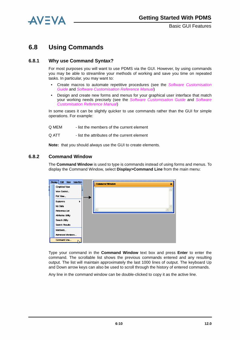
6.8.2 Command WindowThe Command Window is used to type is commands instead of using forms and menus. Todisplay the Command Window, select Display>Command Line from the main menu:
Type your command in the Command Window text box and press Enter to enter thecommand. The scrollable list shows the previous commands entered and any resultingoutput. The list will maintain approximately the last 1000 lines of output. The keyboard Upand Down arrow keys can also be used to scroll through the history of entered commands.
Any line in the command window can be double-clicked to copy it as the active line.
Q MEM - list the members of the current element
Q ATT - list the attributes of the current element
12.06:10

Getting Started With PDMSBasic GUI Features
Clicking the right mouse button in the window displays a pop-up menu:
Note: Macro files can also be dragged into the command window from their location inWindows Explorer.
6.8.3 Note on FilenamesPDMS filenames can be up to 1024 characters long, and can include spaces. For example,the following command can be used within PDMS:
SLIST ‘C:\Program files\Aveva\a temporary file.txt’.
Copy Copies highlighted text in the command window.
Paste Pastes copied text into the command window. Macro text,which has been copied from any source, can be submittedfor processing by pasting it into the Command Window.This paste option will execute each line of the copied text asa separate command as if they had been typed into theCommand Window.
Paste as Macro This option first creates a temporary file containing thecopied macro commands and executes this as a macro.For a large number of commands this gives betterperformance.
Font Size Allows you to select the font size for the text in theCommand Window. The choices are Large, Medium andSmall.
Clear Clears the Command Window.
12.06:11

Getting Started With PDMSBasic GUI Features
12.06:12

Getting Started With PDMSBasic Operations in PDMS
7 Basic Operations in PDMS
Work in any PDMS module is mostly about manipulating the elements and their attributes inone or more databases; either to add, change, read or delete data. You must therefore beable to tell PDMS:
• which database(s) you want to access.• which elements in the database hierarchy you want to access.• what changes, if any, you want to make to the database’s contents.
This chapter tells you how to do these things.
7.1 QueryingYou will often find, when working in PDMS, that you need to check existing informationabout some aspect of the program’s operations. For example, you may need to find outabout any of the following:
• The current usage of the program in terms of users, modules and databases.• The unique code which identifies the process you are running and the station you are
running it from (useful for generating unique work file names).• The current setting of a command option.• The contents of part of a particular database; for example, the current setting of an
attribute or the list of member elements owned by a specific element.• The elements which match specific selection criteria entered by you.
Each module incorporates a Query pull-down menu which allows you to ask about some ofthese topics, the scope of the facility being dependent upon the particular module which youare using. For example, the Query pull-down menu for DESIGN is:
12.07:1

Getting Started With PDMSBasic Operations in PDMS
Not all of the querying operations available from PDMS can be accessed using the GUI. Forthese other (general) options, the QUERY command must be used.
7.2 Current Element and Current List PositionHow PDMS Data is Stored explained the principles of database structures and the conceptof owners and members. This section introduces two new concepts which apply to allaspects of database navigation when you are using a constructor module.
When you are working in any database, PDMS always considers you to be located at aspecific element in that database. This element is known as the Current Element.
The Member List of any element comprises a list of pointers to those elements directlybelow it in the database hierarchy; that is, to those elements which it owns. These pointershave a definite order, identified by numbered positions in the list. In addition to beingnotionally at the Current Element, PDMS also considers you to be at a specific pointer. Thisposition is known as the Current List Position.
As you move about within a database, the Current Element and Current List Position arecontinuously updated so that PDMS always knows where you are. As soon as you access anew element, this becomes the Current Element.
Current Element
Members ofCurrent Element
Pointer toCurrent List Position
1 2 3 4
List Position in Member List
12.07:2

Getting Started With PDMSBasic Operations in PDMS
To view the Current Element and its Member List (in numeric order) at any time, simply clickthe box next to the desired current element in the Design Explorer (see DesignExplorer). The members of the current element will be shown. For example:
Alternatively, give the commands:
7.3 Navigate to a Given ElementThe user normally navigates to an element by means of the Design Explorer or theMembers List.
Q CE to display the current element
Q MEM to display the members list of the current element
12.07:3

Getting Started With PDMSBasic Operations in PDMS
7.3.1 Design Explorer
The Design Explorer provides an easy-to-use, graphical method of exploring the DesignDatabase. It has the following features:
• A Tree View display of DESIGN database elements (which can be expanded andcontracted by clicking the or icons) in the current MDB. The icons in the tree viewrepresent the different DESIGN database element types.
• navigation to database elements in DESIGN databases• the ability to manage items in the display using the Draw List (a separate window
listing the displayed items)• the ability to query the attributes of, rename, delete, copy and paste DESIGN database
elements.
The current element can be identified in the Design Explorer as the highlighted item in thetree view and is displayed in the History list in the main menu bar. The History list containsa list of recently visited items.
Design Explorer replaces most of the functions of the Members List in PDMS DESIGN. TheMembers List is still available from the Display menu.
The Design Explorer will be displayed on entry to DESIGN. If you dismiss it, it can bereinstated by selecting Display>Design Explorer from the main menu bar.
12.07:4

Getting Started With PDMSBasic Operations in PDMS
7.3.2 Members List
As with the Design Explorer, the Members List displays the database elements in thecurrent MDB.
There are a number of ways to navigate from one item to another. The and arrows atthe top of the Members List allow navigation up and down the list at the level of the current
element. For example, if positioned at an EQUI element, selecting would move to the
next EQUI element in the list. Selecting would move back to the previous EQUI element.
The Goto menu at the top of the form can also be used. First select this menu, then selectthe Owner option, this will navigate to the owner of the CE.
Choosing the Goto>Reference option will give a list of further options depending on theCurrent Element. Goto>Reference at EQUI level will only navigate to its owner, i.e. aZONE. If the current element were a nozzle (NOZZ) then Goto>Reference would allownavigation inside the catalogue database via the NOZZ’s Catref attribute.
12.07:5

Getting Started With PDMSBasic Operations in PDMS
PDMS databases may contain many thousands of elements, however, only one elementcan be accessed at a time. As all elements, with the exception of the WORLD, are owned byanother element, deleting, say, a ZONE would cause everything owned by that ZONE to bedeleted as well.
7.3.3 Other ExplorersBesides the Design Explorer (to navigate the DESIGN database), there are similar explorersin DRAFT (to navigate the DRAFT database), SPOOLER and ISODRAFT (to navigate theISOD (spool drawings)) database and PARAGON (to navigate Paragon, Design andProperties databases).
7.3.4 My Data
The My Data window is used to group data into collections. You can then carry outoperations on all the items in a collection in one action. The My Data window is accessed byselecting My Data from the Display menu.
Using the window, you can generate collections of database elements which you may needto work on. Each time you access the My Data window in any of the modules that use it
12.07:6

Getting Started With PDMSBasic Operations in PDMS
(DRAFT, DESIGN, SPOOLER, etc), the data collections generated will be displayed. Thisenables elements to be easily transferred between these modules.
The contents of My Data persists between applications and module switching, as well asbetween design sessions. The data stored is per user, per project in the PDMSUSERdirectory. This means that, for example, in DESIGN you could add elements to My Data andthen switch to DRAFT to use the same data. Note that is the PDMSUSER directory isshared between users, those users will see the same data.
7.4 Modify the Content of a DatabaseYou would normally create, modify or delete elements using the GUI, by means of theCreate, Modify and Delete pull-down menus. The options available depend on the modulethat you are in and the application that is loaded. For example, for the DESIGN module,General Application:
7.5 Drawlist GUITo display the Drawlist, right-click on the Drawlist button and select Drawlist from thepop-up menu:
12.07:7

Getting Started With PDMSBasic Operations in PDMS
The Drawlist form lists the names of items displayed in the 3D View. Adding an item to the3D View (by dragging from the Design Explorer) automatically adds the item to the Drawlist.Individual elements can be added, or an entire Zone or Site.
The visual properties of Drawlist members can be changed using the controls on theDrawlist form.
A Drawlist member can also be added to the My Data form by dragging an item from theDrawlist and dropping it into the My Data form.
The Drawlist can be organised in groups by dragging a column header to the indicatedposition on the form. The gadgets at the top of the list can be used to filter the list by makingselections from the right-click pop-up menu.
Right-clicking on a Drawlist member gives the following shortcut menu:
12.07:8

Getting Started With PDMSBasic Operations in PDMS
The options are:
Multiple elements in the Drawlist can be selected using the standard Microsoft Windows listselection methods (using the mouse together with the Shift or Ctrl keys). Any changes madeto visual properties apply to all selected items.
The Add CE to drawlist button is used to add the current element to the Drawlist.
The Select CE in list button is used to add the current element to the Drawlist (if it has beenadded to the list).
The Remove button removes selected objects from the 3D View.
The Refresh Lists button updates the Drawlist to reflect any additions or removals thathave been made to the 3D View.
7.5.1 Change the Visual PropertiesThe Drawlist form allows the Colour, Edges and Translucency of displayed items to bemodified. The new settings are applied to the selected objects when the Update Displaybutton is clicked. The Reset button resets the Display Settings without applying changes.
• Colour The colour of all selected items in the Drawlist can be changed by selecting from acolour palette; this is displayed when the Colour button is clicked.
• EdgesThe Edges option can be used to display edges on the selected items, or to removeedge display on selected items.
Note: The current element will be displayed in the current element colour and so will beunaffected by colour changes until another element is made current.
When modifying the visual properties of a top-level element in the Drawlist, lowerlevel elements in the list owned by this element will also be modified.
• Translucency
Setting the translucency of displayed items allows you to see through the translucentitems to items behind them in display. The degree of opaqueness can be controlledselecting the required percentage translucency on the slider bar. On this scale, 0% is asolid colour and 100% is completely transparent.
Note that items drawn with translucent colour may appear to overlap with each other insome view directions. This is not a problem, it is an effect of viewing one translucent
Navigate To - Makes the selected item the current element.
Hide - Temporarily removes selected items from the display.
Show - Shows items that were previously hidden.
Remove - Remove the selected item from the Drawlist. A similar operationcan be performed from within Design Explorer, or using theRemove button.
Add to My Data - Adds the selected items to the My Data list. It is also possible todrag and drop an item from the Drawlist into the My Data form.
12.07:9

Getting Started With PDMSBasic Operations in PDMS
item through another. It is often better to draw translucent items with edges shown for aclearer view of the item.
7.5.2 Display of Graphical SelectionThe Graphical Selection tab lists those objects in the current graphical selection. TheDisplay Settings can be modified for these objects in the same way as for the Drawlist tab.
7.5.3 Display of PrimitivesWhen an object is displayed in the Drawlist tab, its primitives can be displayed in thePrimitives tab. This allows the control of the display for individual primitives.
7.5.4 Other Drawlist Functions
The Drawlist button on the 3D View toolbar has both a left-click and a right-click function,described below.
Pick Object to Hide
In normal operation, the 3D view allows an object to be hidden with a right mouse click in thegraphical view. However during a multi-pick sequence, this function is not available. For
12.07:10

Getting Started With PDMSBasic Operations in PDMS
example, when defining a clipping box by two picks, if the object of interest for the secondpick is obscured, it cannot be picked.
A left click on the Drawlist button sets the graphical view so that the next 3D object pickedwill be hidden. This has the effect of temporarily suspending any current multi-picksequence and allowing the obscuring object to be picked. This will cause the picked objectto be hidden whereupon the multi-pick sequence will be restored, allowing the user tocomplete the sequence.
Show Hidden Objects
Once an object has been hidden in the graphical view, it can be reshown using either of twomenu options available with a right click on the Drawlist button.
The first option, Show Last Hidden Object(s) reshows the objects most recently hiddenduring the current session, provided that they are still in the drawlist.
The second option, Show All Hidden Objects reshows all objects hidden during the currentsession, provided that they are still in the drawlist.
The third option, Show Hidden Objects displays a form allowing the user to select objectsto be reshown. The form lists all the objects in the drawlist for this view that are currentlyhidden.
12.07:11

Getting Started With PDMSBasic Operations in PDMS
Local Views
When a graphical view is first displayed from the main DESIGN menu, it will display anyobjects in the global drawlist. The Drawlist button right-click menu provides an option tocreate a new local view of the graphical selection. The new view will be created with its owndrawlist containing only those objects in the graphical selection.
Clone Views
The Drawlist button also provides an option to create a clone of the current view. Thiscreates another view using the same drawlist as the current view. This may be the globaldrawlist or a local drawlist depending on how the current view itself was created.
Note: Undoing the deletion of an element will result in the element being added to theglobal drawlist, but it will not be re-added to any local drawlist which contained thedeleted element.
12.07:12

Getting Started With PDMSBasic Operations in PDMS
Representation
When a Drawlist is created, it inherits the current representation settings from the globaldrawlist. A subset of these settings can then be controlled for a particular view by displayingthe Representation form using the Drawlist button
7.6 PDMS Search UtilityThe PDMS Search Facility enables the user to search for model items in all the graphicalapplications and list the search results in a table. To display the Search form select:Display>Search Utility.
12.07:13

Getting Started With PDMSBasic Operations in PDMS
Name Contains You can search for items where name contains a specifiedstring. The search function is case-sensitive.
Item Type Once or more item types can be entered in this field,separated by a space, comma or semi-colon such as:
12.07:14

Getting Started With PDMSBasic Operations in PDMS
The history for the current session in the combo-box is remembered by the search tool andcan be cleared at any time by selecting the Clear History option from the drop-down list.
Clicking the Search button starts the search process.
Search Filters
Two scopes for the search can be set in the Search Filters section of the Search form.
1. Hierarchical Search beneath a Ceiling
When the search tool is first opened during a session, the default scope will have theworld element (/*) as the ceiling of the search within the current database (e.g. Design,if within the Design application). To change this ceiling, select the Beneath Itemcheckbox combo-box. Alternatively, click the CE button to set the current element asthe Ceiling for the search.
The databases listed in the In Database combo-box are those that are available to youand the combo-box will automatically update if the database item exists in any of thosedatabases. Similarly, if you change the database type in the combo-box then thedatabase item currently displayed will be checked, and if not found in that database,the ceiling of the search scope will be reset to world.
The database items entered in the Beneath Item combo-box will be rememberedthroughout the session. This history can be cleared by selecting the Clear Historyoption from the pull-down list.
2. Volumetric Search within an Existing Model Item or an Explicit Volume
To set the search scope for Volumetric Searching, select the In Volume checkbox toactivate the Of Item and Explicit Volume search scope approaches.
With the Of Item checkbox selected, enter a valid model item for the scope of thesearch in the adjacent combo-box. Alternatively, click the CE button to enter the currentelement in the combo-box. The items found will reside within the volume of thespecified model item. A Clear History option is available from the drop-down list.
With the Explicit Volume checkbox selected, you can specify the opposite 2 corners ofa 3D box in which to conduct a search by setting the appropriate coordinates in the X,Y and Z boxes.
The Completely within and Partially within option buttons, which are applicable toboth volumetric search approaches, allow you to specify whether the found items existcompletely or partially within the specified volume.
Attribute Filters
You can set one or more attribute filters for the search. The specified attributes will apply toeach item type listed. If there is more than one attribute filter specified then the found itemswill satisfy all of the attribute filters.
EQUI PIPE, NOZZ; TEE
Selecting the [ALL] option from the drop-down list finds allitem types within the current scope. This field requires avalid entry before the search process is initiated.
Display Search Results Opens the Search Results table.
12.07:15

Getting Started With PDMSBasic Operations in PDMS
To add an attribute filter, select the Add Filter action label and then enter a valid attribute inthe displayed field. Click in the Operator field and accept the suggested Operator or selecta different one from the drop-down list. With the Operator selected, click in the Value fieldand enter an appropriate value. Accepting these settings enters them in the filter grid.
In List Operator
The In List Operator enables you to specify a list of values (separated by spaces) for thespecified attribute value - these can be numeric or non-numeric, depending on the type ofthe attribute. For example, Attribute=AREA, Operator="In the List", Value="0 1 3", would finditems which have AREA attribute equal to either 0 or 1 or 3.
In Range Operator
The In Range Operator enables you to specify a range of 2 numeric values i.e. an upperand a lower limit, inclusive. So, for example, Attribute=AREA, Operator="In the range",Value="1 10", would find items which have AREA attribute equal to any numeric valuebetween and including 1 and 10.
If the attribute is changed once it is in the grid, then the Operator and Value fields willupdate accordingly.
Delete Filter Selecting one or more rows and then clicking this actionlabel removes the appropriate attribute filters from the grid.
12.07:16

Getting Started With PDMSBasic Operations in PDMS
7.6.1 Saved SearchesYou can save the searches that you have created, and these will be available in futuresession of PDMS. The application you are using will determine where you will be able tosave searches and which saved searches are available to you for use. By default all userswill be able to save searches into the local settings directory of the local computer.
A saved search is composed of the criteria used to determine the search, together with thecolumns which are to be output in the search results form.
In order to run a saved search you can select a named search and press the search button.The results will be output into the grid on the search results form. The main search form willbecome populated with the search criteria.
7.6.2 Create a Saved SearchYou can save a search at any time by selecting the action label Create "Saved Search"Based on Current Search Criteria. This will prompt for the name of the search and thelocation on the hard drive of your computer (this is determined by the application you areusing).
7.6.3 Delete a Saved SearchSelect the action label Delete Selected Saved Search to delete the current saved search.Note that you can also delete the saved search from the location on your computer, and itwill not be loaded the next time you start PDMS.
Note: There is also a toolbar for saved searches. This allows you to run and delete savedsearches without having to open the main Search form.
7.6.4 Explorer Bar FunctionalityThe Scope of Search and Attribute Filters explorer bars can be open and closed usingthe expand/collapse button at the end of each bar. Also the positions of the bars can beinterchanged by dragging and dropping one above or beneath the other.
7.6.5 Search ResultsAs soon as the search is underway the text on the Go button changes to Stop, and this canbe clicked at any time to stop the search.
12.07:17

Getting Started With PDMSBasic Operations in PDMS
On completion of the search the Search Tool will automatically open the Search Resultstable and populate the table with the search results.
Note: If the Search Results form is closed, then it can be opened at any time by selectingthe Display Search Results link label on the Search form, or from the Displaytoolbar menu.
The Search Results form contains a grid control. You can specify the columns that aredisplayed - each column represents an attribute or a valid PDMS expression of an item inthe system.
You can select either one or more rows in the Search Results form and perform specifiedactions on this data. For example, within DESIGN, you can drag & drop one or more itemsinto the 3D graphical view. All menu actions can be specified within the AVEVAcustomizable menu builder application.
Search Results functionality is accessible through the right-click pop-up menus. Right-clicking on the column titles shows the general functionality menu and right-clicking onsearch results shows a menu of operations that can be performed on the selected items.
12.07:18

Getting Started With PDMSBasic Operations in PDMS
7.6.6 Functionality on the Search Output Form
General Functionality
Set Columns in the Search Results
Attribute columns can be created, modified and deleted with the Column settings function.To access this function, select the Column Setup option from the white-space pop-up menuto display the Column Setup form.
Using this form, you can change the order of columns, as well as deleting and addingcolumns.
Note: The changes to the order of the columns will not be shown until a new search isinitiated.
Clear the Search Results
The data in the Search Results form can be cleared with the Clear Grid Results white-space pop-up menu command.
Search Results Form Settings• Enable Group Sorting• Enable Filtering• Display Column Summaries• Enable Column Sort• Suppress "unset" values• Suppress "Nulref" values
Interaction Mode• Read Only• Single Cell Edit
12.07:19

Getting Started With PDMSBasic Operations in PDMS
• Bulk Cell Edit
Feedback Colours• Read Only Cell Colour• Edit Success Colour• Edit Fail Colour• Reset Default Feedback Colours
Reset Cell Feedback
Following cell editing operations the cell feedback (highlight colour and edit feedback tooltip) can be cleared.
Refresh
All cell values are refreshed from the data source. This refreshes the grid if the data sourceand displayed information are out of synchronisation.
Save as Excel
The Export to Excel menu option enables the search results to be saved to a specifiedExcel file (.xls).
Print Preview
This enables the search results to be previewed in a Print Preview window and thenprinted.
Row Selection MenusThe row selection menus are module dependent.
Other Functionality
Drag & Drop
Selected rows can be dragged and dropped into an appropriate drag target - such as theDesign 3D View.
Adding to My Data
Selected rows in the Search Results can be added to My Data by drag and drop or throughthe appropriate menu option.
Customizable Menus
See the Software Customisation Guide.
Filtering etc
See GUI Grid Data.
7.7 GUI Grid DataData that is presented on a grid on a form can be customised using the grid controlfunctionality. Each instance of the grid control will be utilised and customised in each
12.07:20

Getting Started With PDMSBasic Operations in PDMS
application in a different way. Not all of the available functionality described here willnecessarily be available on any particular instance of the data grid.
The following figure shows a typical data grid display, comprising PIPE and EQUI items.
Note: The attribute ‘POSITION’ is invalid in PIPE items, and is indicated by an appropriateicon. Similarly, ‘PSPEC’ is invalid on EQUI items.
In addition to the functions described below, right-clicking an item can display a pop-upmenu with options to execute various commands on these items, such as ‘Add to 3D View’.
7.7.1 Move around the Grid using the KeyboardIn single or bulk edit mode, use the Tab key to move form one cell to the next. Use Shift +Tab to move to the previous cell.
In read-only mode, use the Tab key to move from one row to the next. Use Shift + Tab tomove to the previous row.
Both horizontal and vertical scroll bars are available in the grid.
7.7.2 SelectionIn read-only mode, click anywhere on a row to select it:
12.07:21

Getting Started With PDMSBasic Operations in PDMS
In single edit mode, clicking on a cell places that cell in edit mode:
In bulk edit mode, double clicking on a cell places that cell in edit mode. A single click on acell selects the cell itself. Use the standard windows selection methods (left mouse click plusCtrl and Shift keys) to select multiple groups of cells. A left mouse key drag operation canalso be used to select multiple cells:
12.07:22

Getting Started With PDMSBasic Operations in PDMS
In bulk edit mode, Fill Down, Fill Up and Copy/Paste operations apply to all cells currentlyselected.
To select an entire row in single or bulk edit mode, click on the row selector column at theleft of the grid:
In both read-only and single or bulk edit modes, multiple rows are selected using thestandard windows selection methods (left mouse click plus Ctrl and Shift keys).
7.7.3 Grid SplittingThe grid can be split into any number of smaller grids, by clicking on the splitter bars anddragging them to the required location. These are located at the top of the vertical scroll barand at the left of the horizontal scroll bars. The figure below shows the grid split into fourareas:
12.07:23

Getting Started With PDMSBasic Operations in PDMS
To return to the standard grid display, drag the splitter bars to the top and left of the grid toremove them.
7.7.4 Pin Rows and ColumnsThese functions are useful when scrolling through large amounts of data.
If the row selector column is displayed for a data grid, rows can be pinned (i.e. fixed to thetop of the grid) by clicking on their pin icons. Another click on the icon unpins that row.Pinnned rows are shown in yellow:
Similarly, columns can be pinned to the left of the grid by clicking on the pin icon in thecolumn header. Clicking again unpins the column.
7.7.5 Row and Column SizeThe height of all rows can be changed by dragging a row separator in the row selectorcolumn. All rows have the same height.
12.07:24

Getting Started With PDMSBasic Operations in PDMS
Individual column widths can be changed by dragging the column separator in the headingarea.
Column widths can be changed to the width of the widest entry in the column by double-clicking on a column separator.
7.7.6 Column Re-orderThe columns in a grid can be arranged in a different order by dragging and dropping acolumn header to a different position, as shown below. The system assists the operation bydisplaying red arrows for valid drop points.
7.7.7 Column SortThe data in a column can be sorted alphabetically by clicking on a column header; a secondclick will reverse the direction of the sort. An up or down arrow symbol at the right of thecolumn header indicates the sort direction. Only one column at a time can be sorted in thisway. In the following example, the DESCR column has been sorted alphabetically.
7.7.8 Column FilterTwo different methods of filtering are available on each column, depending on attribute datatype: Auto-Filtering and Pattern Match filtering.
• Auto-Filtering
12.07:25

Getting Started With PDMSBasic Operations in PDMS
This filtering method enables data in a column to be filtered according to the data inthat column (as in Microsoft Excel). Alternatively, data can be filtered on blank or non-blank data.
Clicking on the down arrow button at the right of the column under the header displaysa drop-down list from which an option can be selected: The mouse pointer may need tobe moved into this area for the icon to become visible.
• Pattern Match FilterThis type of filtering enables data to be filtered by searching for patterns within the data,such as 'Starts with', 'Ends with', 'Contains', etc. Clicking on the icon at the left of thecolumn under the header displays a drop-down list from which an option can beselected:
The filter text is then entered into the area to the right of the filter icon.
Note that different columns can be set with different filters, to provide compound filtering.
The filter on an individual column can be cleared by clicking the Clear Filter button. Themouse pointer may need to be moved into this area for the button to become visible.
To clear all the filters in the grid, select the Clear All Filters button at the top of the rowselector column:
12.07:26

Getting Started With PDMSBasic Operations in PDMS
7.7.9 Numeric Data FunctionsFor columns which contain numeric data, several numeric operations are available, theresults being displayed at the foot of the column. This functionality is available by clicking onthe summation symbol in the header of the column.
7.7.10 Group SortingGroup Sorting allows the grid data to be shown in groups based on the data in the columns.To display the data in groups, drag a column header into the Group Sort Area above thegrid data, as shown below:
12.07:27

Getting Started With PDMSBasic Operations in PDMS
In the example below, the 'Type' column has been dragged into the Group Sort Area andthe data is therefore grouped according to 'Type':
To remove the group sorting, drag the tile from the Group Sort Area back into the headingrow.
Multiple group sortings are possible by dragging other column headers into the Group SortArea. The following figure shows a grid which is first ordered on 'Type', then on 'Area'.
12.07:28

Getting Started With PDMSBasic Operations in PDMS
7.7.11 Miscellaneous Grid Data FunctionsThe following functions may be available on some forms (via a right-click menu), dependingon the application/utility.
• Save to ExcelThis enables the grid data to be saved to an Excel file.
• Import an Excel SpreadsheetIf this option is available, the Excel file must contain a set of column headings in thefirst row of the file, followed by the data beneath the headings.
• Print Preview the Grid DataProvides a facility to print preview the grid data, prior to printing it.
12.07:29

Getting Started With PDMSBasic Operations in PDMS
12.07:30

Getting Started With PDMSProduct Range
8 Product Range
8.1 Introduction
8.1.1 ProductsAVEVA Plant is a set of integrated plant design and engineering applications combined withopen and flexible lifecycle management solutions. It provides the fastest, most productiveand risk-free tool set to design, build and operate plant of any size and complexity.
AVEVA NET
AVEVA NET is an application-neutral platform for all engineering data for the plant industry.On this platform, a virtual plant information model is created, that enables all types oflifecycle data - regardless of the programs that created them - to be made available anduseful to a wide range of existing applications, processes and therefore a wide range ofusers across organisations. NET can be used to develop additional applications to meet thespecific lifecycle information management needs of both EPCs and Owner Operators.
VPE P&ID
VPE P&ID is an intelligent P&ID application, based on AutoCAD. Fully compatible with VPEWorkbench, with two-way synchronisation, the application enables smart on- and offlinedatabase operation, with a full range of reports.
VPE Workbench
VPE Workbench is an integrated engineering database which manages the evolvingengineering descriptions of all tagged items in a plant.
P&ID Manager
P&ID Manager is an application for importing P&IDs from different authoring systems intothe PDMS database, to allow consolidation of all P&ID data in a project. Inconsistenciesbetween P&ID drawings can be identified and highlighted.
Schematic 3D Integrator
Schematic 3D Integrator is an integration application that provides data consistencybetween P&IDs and the PDMS 3D model. It can be used to build the 3D model from P&IDdata, or to associate an existing 3D model with the P&ID, so that inconsistencies can behighlighted and corrected during design development.
PDMS
PDMS is a datacentric, multi-disciplinary design environment for the 3D modelling ofprocess plant. It has modules for the design of equipment, piping, HVAC, structure and
12.08:1

Getting Started With PDMSProduct Range
cable trays. Modelling is carried out using a customer-defined catalogue and specification,in a full 3D environment, with the support of tools that ensure a clash-free design. A fullrange of drawings and pipe isometrics can be produced automatically from the model.
Multi-Discipline Supports
Multi-Discipline Supports is an additional application for PDMS that enables the detaileddesign, material take off and automated drawing production of supports for piping, ductingand cable trays. A comprehensive range of standards are included, in addition to user-defined catalogue customisation.
Cable Design
Cable Design is an application for the design of cables, including their routing in cablewaysand through penetrations. Output includes cable schedules with routes, cable cutting listsand material take off.
Laser Model Interface
Laser Model Interface provides online verification of as-built 3D model data by interfacingwith point cloud data from leading laser scanning systems. The interface enables revampsto be undertaken with confidence, using the measurement, modelling tools and clashmanagement functions of PDMS.
Pipe Stress Interface
Pipe Stress Interface provides two-way exchange of information between PDMS and theCAESAR II pipe stress system. Piping designers and stress engineers can exchange designand stress information seamlessly, to eliminate data re-entry and duplication.
Model Management
A set of powerful model management tools to maximise design productivity and quality.Functions include:
• Managing and reporting the progress, status and attributes of plant objects in PDMS • Producing and controlling deliverables (isometrics, equipment drawings etc.) • Populating a 3D PDMS model directly from VPE P&ID data • Comprehensive clash management and resolution
Final Designer
Final Designer can be used at any point in the drawing production process to produceAutoCAD drawings from PDMS and to edit them in a closely integrated environment.
Global
Global allows users at multiple sites to work together online on the same project. It controlsthe release of data to each site and ensures that all sites and users have access to thelatest approved data, right down to attribute detail. Global operates across low bandwidthsand is tolerant of communication faults.
Review
Review is a powerful 3D visualisation tool for large, complex plant models. With featuressuch as walk-through, animation, and high-quality photo-realistic images, Review lets youanalyse designs and communicate complex ideas.
12.08:2

Getting Started With PDMSProduct Range
ReviewShare NEW!
ReviewShare brings together 3D design review, mark-up and collaboration using 3Dmodels, embedded screenshots, document views and hyperlinks, into one application.ReviewShare works with a large number of 3D data formats, not just PDMS, with server-based streaming technology or desktop model files.
VPRM
VPRM allows the effective management of materials, vendor documents, designdocuments, progress and costs, through all phases of a project from inception to handover.It includes an overarching management information system summarising all VPRM activitiesfor project management.
NET Portal
NET Portal is a web-enabled platform for the integration and collaborative use ofengineering information. 3D models, schematics, documents and data from any applicationcan be accessed and navigated in context, with full intelligence, without needing the sourceapplications that originally created the data.
12.08:3

Getting Started With PDMSProduct Range
12.08:4

Getting Started With PDMSGlossary of Terms and Abbreviations
9 Glossary of Terms and Abbreviations
9.1 IntroductionThis glossary comprises:
• Technical terms relevant to PDMS, with brief explanations of their meanings in thecontext of AVEVA programs.
• Abbreviations and acronyms used throughout the PDMS documentation, withexpansions to their full derivations.
It does not list general process engineering terms, with which you are assumed to befamiliar.
9.2 DefinitionsAdd-inAn add-in provides a means of adding functionality. An add-in application appears onthe applications menu, which provides a method of switching to it.
Applicationware (‘Appware’)A suite of forms and macros designed for use with a specific design task, for examplepipework design.
AttributeA specific item of data which defines one of the properties of an element in adatabase. An element is fully specified by combining all its attributes.
Batch ModeA method of running a computer program without user intervention; for example,overnight. The command inputs are stored in a file and then read sequentially into thecomputer. The opposite is Interactive Mode.
CancelRemoves a form without making any changes (To cancel a graphical selectionoperation), press the Esc key.
CrosshairsA crosshair cursor. A horizontal and a vertical line on a display screen whoseintersection represents the cursor position.
12.09:1

Getting Started With PDMSGlossary of Terms and Abbreviations
Current ElementThe element in a database at which you are notionally situated at a given stage ofdatabase navigation.
DatabaseAll information which exists about an AVEVA design project, whether administrative ortechnical, is stored in a series of hierarchical databases.
DefaultAn option selected automatically if you do not specify any particular choice from anavailable range of commands or attribute settings.
DisciplineA branch of a project that is concerned with specific types of Plant items (e.g. HVAC,Piping, Steelwork, Equipment) or a specific area of the design process (e.g. ModelManagement, 2D drawing).
Docking/DockableThis describes forms and menu bars that can be attached in appropriate places to theframe of the main PDMS window.
Drag-and-dropSelect with mouse and then drag (holding the mouse button down) to a different place.
ElementA discrete item of data held in a database; identified by number and/or name anddefined by its attributes.
ExpressionA mathematical or logical definition, the calculated result of which is to be used as acommand argument.
FileAn identifiable part of the computer's memory used to store data. Data may be addedto and removed from a file, or may be manipulated as a whole by operations on thecomplete file.
FilenameThe name of a file in the computer's operating system. When referenced from withinPDMS the filename must be preceded by a / symbol, or in some contexts surround byquotes. The symbol is not part of the filename as defined by the computer's operatingsystem.
Form (also referred to as a Dialogue Box)That part of a graphical user interface screen into which you may enter the settings ofparameters or command arguments, usually with prompting text which shows youwhat to enter at each location.
Graphics FileSee Plotfile.
GROUPA collective element which can be used to form temporary links between otherwiseunrelated elements in a database.
HeadThe input end of a BRANCH (under normal flow conditions).
12.09:2

Getting Started With PDMSGlossary of Terms and Abbreviations
Hit RadiusThe maximum acceptable error in identifying a point on a screen using a graphicspointer. If the distance from the pointer position to the intended location is larger thanthe hit radius, the location will not be identified.
Interactive ModeThe method of operation whereby you perform an operation using the mouse and/orkeyboard and wait for PDMS to interpret and act upon it before you perform the nextoperation. The opposite is Batch Mode.
Level (drawing)An attribute of an element in a Design database which defines whether or not thecorresponding item is to be shown when a drawing is plotted. The levels to be drawnare specified as part of the plotting command.
Level (hierarchic)The vertical position at which a given type of element is situated in a databasestructure; analogous to a generation in a family tree.
MacroA sequence of commands stored as a text file. When the macro is called from withinPDMS, the command processor reads each line of the file in turn and behaves as ifthe commands were being directly entered.
Member (of an Element List)A lower-level element linked immediately below another element (its owner) in adatabase hierarchy. A Group Member is an exception in that it is linked only indirectlyto the GROUP, which is a parent but not its owner.
Member (of a Team)A named PDMS user who is linked with other users (as a team) who share commonaccess rights to one or more databases.
ModuleA subdivision of the overall PDMS program which is used to carry out a particular typeof operation on the databases. Each module has its own name within the programsuite.
Multiple Database (MDB)A group of databases linked together administratively for a specific purpose. You canonly access a database if you have access rights to an MDB which contains it.
My Dataa storage area for remembering PDMS data for future use. Typically used to copycollections of elements from one module to another.
NameA name in PDMS is an element identifier which you allocate to it. It is an alphanumericstring prefixed by a / symbol. This identifier is always additional to the element'sreference number, which is allocated automatically by PDMS.
OffspringA lower-level element linked anywhere below another element (one of its parents) in adatabase hierarchy. A member is a special case of an offspring.
OwnerOne higher-level element linked directly above another element (one of its members)in a database hierarchy.
12.09:3

Getting Started With PDMSGlossary of Terms and Abbreviations
ParameterA -variable item of information (value, text etc.) which must be defined before acommand can be executed unambiguously.
ParentA higher-level element linked anywhere above another element (one of its offspring) ina database hierarchy. An owner is a special case of a parent.
PIPEAn element, comprising an assembly of BRANCHes, which defines part of a complexpiping system. The term has a specific meaning in PDMS which may not correspondwith its usual engineering meaning.
PlotfileA file which contains encoded graphics data. The file's contents can be unspooled to aplotter or graphics screen when the corresponding drawing is to be generated.
Pointer (1)An indicator (also referred to as the cursor) on a display screen which identifies oneof two types of location:
An alpha pointer (e.g. a flashing block or bar) shows where the next inputcharacter will appearA graphics pointer (e.g. an arrowhead) identifies a location or an element in thedepicted part of the design model.
Pointer (2)A link between elements or attributes, indicating the path by which information istransferred logically between the various parts of the databases.
P-point (Principal Point)An imaginary location and direction used to manipulate and interconnect elementswhich represent physical entities in the design model. A P-line is a p-point extruded ina specific direction.
PrimitiveA fundamental design shape (box, cylinder etc.) used to build up the design of aphysical entity in the design model or component catalogue.
Read-onlyAn access category that allows you to look at the contents of a database or file but notto modify them.
Read/WriteAn access category that allows you to look at the contents of a database or file and tomodify them.
Enter (key)The carriage return key on the keyboard. Used to end each typed command line andsend its contents to the command processor. Also referred to as the Return key.
SelectionA selection of objects defined using the 3D graphical view.
Shortcut Menua context-sensitive menu activated by the secondary (usually right-hand) mousebutton.
12.09:4

Getting Started With PDMSGlossary of Terms and Abbreviations
Syntax (Of Commands)the rules which define precisely how a command line must be entered so that PDMScan interpret your instructions unambiguously. Syntax is usually specified by usingdiagrams to show the valid command sequences.
TailThe output end of a BRANCH (under normal flow conditions).
TeamAn administrative grouping of PDMS users who share common access rights to one ormore databases.
Textual ExpressionAn expression which manipulates text simply as strings of alphanumeric characterswithout regard to their overall meaning.
Title barThe top of a window, containing its title.
ToolbarA collection of GUI icons, used to trigger the GUI actions.
UnspoolerA translation program which allows graphical output files (plotfiles) produced by acomputer program to be input to an offline plotter. Each combination of output formatand plotter type requires a specific unspooler.
User-Defined AttributeA database attribute whose name and type of content are defined by the user ratherthan by the default PDMS structure.
WORLDThe highest level element in any database; always allocated the symbol /* as itsPDMS name.
9.3 Abbreviations and AcronymsAbbreviations which are thought to be self-explanatory, particularly those which are simplythe first few letters of an obvious word, are not listed.
ABA Area Based ADP
ADP Automatic Drawing Production
ASCII American Standard Code for Information Interchange
API Application Programming Interface
CATREF Catalogue Reference
CE Current Element
CL Centreline
COCO Connection Compatibility
CPU Central Processor Unit
12.09:5

Getting Started With PDMSGlossary of Terms and Abbreviations
CREF Connection Reference
CTORU Circular (cross-section) Torus
DABACON Database Constructor
DAC Data Access Control
DB Database
DDL Data Definition Language
DXF Drawing Exchange Format (as used by AutoCAD®)
GTYP Generic Type
GUI Graphical User Interface
HPGL Hewlett Packard Graphics Language
I/O Input/Output
IGES International Graphics Exchange Specification
Iso ADP Isometric ADP
LJSE Lap Joint Stub End
MDB Multiple Database
MOM Model Object Manager
MDS Multi-Discipline Supports
OS Operating System
Pn P-point n (where n is an integer)
PA P-Arrive or Arrive P-point
PADD Production of Annotated and Dimensioned Drawings
PDMS Plant Design Management System
PH Pipe Head
P&ID Piping and Instrumentation Diagram
PID Piping and Instrumentation Diagram
PL P-Leave or Leave P-point
PML Programmable Macro Language
POHED Polyhedron
PT Pipe Tail
PTRANS Percent (%) Variable Translator
PVOL Preferred Volume or Penalty Volume
Q Query
12.09:6

Getting Started With PDMSGlossary of Terms and Abbreviations
Refno Reference Number (of an element in a database)
RTORU Rectangular (cross-section) Torus
SHU Standard Hookup
SKEY Symbol Key
SPCOM Specification Component
SPREF Specification Reference
STYP Symbol Type
UDA User-Defined Attribute
VDM View Definition Matrix
WN Weld Neck
2D or 3D Two- or Three-dimensional
@ Crosshair cursor location
12.09:7

Getting Started With PDMSGlossary of Terms and Abbreviations
12.09:8

Index
Getting Started With PDMS
AADMIN module . . . . . . . . . . . . . . . . . . . . 2:7
BButton
control . . . . . . . . . . . . . . . . . . . . . . . . 6:3radio . . . . . . . . . . . . . . . . . . . . . . . . . 6:2toggle . . . . . . . . . . . . . . . . . . . . . . . . 6:3
CCheck box . . . . . . . . . . . . . . . . . . . . . . . . 6:3Command Window . . . . . . . . . . . . . . . . 6:10Control button . . . . . . . . . . . . . . . . . . . . . 6:3Current element . . . . . . . . . . . . . . . . . . . 7:2Current list position . . . . . . . . . . . . . . . . . 7:2
DDatabase
CATALOGUE . . . . . . . . . . . . . . . . . . 3:2COMMS . . . . . . . . . . . . . . . . . . . . . . 3:3DESIGN . . . . . . . . . . . . . . . . . . . . . . 3:2DICTIONARY . . . . . . . . . . . . . . . . . . 3:3hierarchy . . . . . . . . . . . . . . . . . . . . . . 7:2MISC . . . . . . . . . . . . . . . . . . . . . . . . 3:3PADD . . . . . . . . . . . . . . . . . . . . . . . . 3:2PROPERTIES . . . . . . . . . . . . . . . . . 3:3SYSTEM . . . . . . . . . . . . . . . . . . . . . . 3:3TRANSACTION . . . . . . . . . . . . . . . . 3:4
DESIGN module . . . . . . . . . . . . . . . . . . . 2:3Diagrams . . . . . . . . . . . . . . . . . . . . . . . . . 2:5Dockable Forms . . . . . . . . . . . . . . . . . . . 6:5
DRAFT module . . . . . . . . . . . . . . . . . . . 2:4Drawlist GUI . . . . . . . . . . . . . . . . . . . . . . 7:7
EEscape key/button . . . . . . . . . . . . . . . . . 6:5
GGrid Data . . . . . . . . . . . . . . . . . . . . . . . 7:20
IISODRAFT module . . . . . . . . . . . . . . . . 2:5
LLEXICON module . . . . . . . . . . . . . . . . . . 2:7List
scrollable . . . . . . . . . . . . . . . . . . . . . 6:3
MMember . . . . . . . . . . . . . . . . . . . . . . . . . 7:2
(of element) . . . . . . . . . . . . . . . . . . . 7:2list . . . . . . . . . . . . . . . . . . . . . . . . . . 7:2
Menubar . . . . . . . . . . . . . . . . . . . . . . . . . . 6:4pull-down . . . . . . . . . . . . . . . . . . . . . 6:4
MONITOR Module . . . . . . . . . . . . . . . . . 2:7Mouse buttons
functions . . . . . . . . . . . . . . . . . . . . . 6:1
12.0Index page 1

Getting Started With PDMS
OOption button . . . . . . . . . . . . . . . . . . . . . 6:2Owner . . . . . . . . . . . . . . . . . . . . . . . . . . . 7:2
PPARAGON module . . . . . . . . . . . . . . . . . 2:6Product Range . . . . . . . . . . . . . . . . . . . . 8:1Project Folder . . . . . . . . . . . . . . . . . . . . . 3:1Prompts . . . . . . . . . . . . . . . . . . . . . . . . . . 6:5PROPCON module . . . . . . . . . . . . . . . . . 2:6Pull-down menu . . . . . . . . . . . . . . . . . . . 6:4
RRadio button . . . . . . . . . . . . . . . . . . . . . . 6:2
SScrollable list . . . . . . . . . . . . . . . . . . . . . . 6:3Search Utility . . . . . . . . . . . . . . . . . . . . . 7:13SPECON module . . . . . . . . . . . . . . . . . . 2:6SPOOLER module . . . . . . . . . . . . . . . . . 2:4Status bar . . . . . . . . . . . . . . . . . . . . . . . . 6:5Submenu . . . . . . . . . . . . . . . . . . . . . . . . . 6:4
TText box . . . . . . . . . . . . . . . . . . . . . . . . . 6:2Toolbar . . . . . . . . . . . . . . . . . . . . . . . . . . 6:4
12.0Index page 2
![Skaffold - storage.googleapis.com · [getting-started getting-started] Hello world! [getting-started getting-started] Hello world! [getting-started getting-started] Hello world! 5.](https://static.fdocuments.us/doc/165x107/5ec939f2a76a033f091c5ac7/skaffold-getting-started-getting-started-hello-world-getting-started-getting-started.jpg)