
61WG/30WG 020-090 Pro-Dialog+ Control
24
61WG/30WG 020-090 Pro-Dialog+ Control Operation instructions
Transcript of 61WG/30WG 020-090 Pro-Dialog+ Control

61WG/30WG 020-090
Pro-Dialog+ Control
Operation instructions

2
The cover graphics are solely for illustration and forms no part of any offer for sale or any sale contract. The manufacturer reserves the right to change the design at any time without notice.
Contents
1 - SAFETY CONSIDERATIONS ............................................................................................................................................... 31.1 - General ..................................................................................................................................................................................... .31.2 - Avoid electrocution ................................................................................................................................................................. .3
2 - GENERAL DESCRIPTION .................................................................................................................................................... 32.1 - General ..................................................................................................................................................................................... .32.2 - Abbreviations used.................................................................................................................................................................. .3
3 - HARDWARE DESCRIPTION ............................................................................................................................................... 33.1 - General ..................................................................................................................................................................................... .33.2 - Electrical supply to boards ..................................................................................................................................................... .43.3 - Light emitting diodes on boards ............................................................................................................................................ .43.4 - The sensors ............................................................................................................................................................................... .43.5 - The controls .............................................................................................................................................................................. .43.6 - Connections at the user terminal block ................................................................................................................................ .4
4. SETTING UP PRO-DIALOG+ CONTROL .......................................................................................................................... 64.1 - General features ...................................................................................................................................................................... .64.2 - Default screen characteristics ................................................................................................................................................ .64.3 - Password screens ..................................................................................................................................................................... .64.4 - Menu screen characteristics ................................................................................................................................................... .64.5 - Data screen or configurable parameter characteristics ...................................................................................................... .64.6 - Parameter modification .......................................................................................................................................................... .74.7 - Operating mode screen........................................................................................................................................................... .74.8 - Menu tree structure ................................................................................................................................................................. .84.9 - Detailed menu description ..................................................................................................................................................... .9
5 - PRO-DIALOG+ CONTROL OPERATION ...................................................................................................................... 165.1 - Start/stop control ................................................................................................................................................................... .165.2 - Heating/cooling/standby operation ..................................................................................................................................... .165.3 - Heat exchanger water pump control................................................................................................................................... .175.4 - Control interlock contact ..................................................................................................................................................... .175.5 - Control point.......................................................................................................................................................................... .175.6 - Capacity control .................................................................................................................................................................... .185.7 - Demand limit ......................................................................................................................................................................... .185.8 - Night mode ............................................................................................................................................................................. .185.9 - Control of a boiler ................................................................................................................................................................. .195.10 - Master/slave assembly ........................................................................................................................................................ .195.11 - Heating module (HDC) control ........................................................................................................................................ .19
6 - DIAGNOSTICS - TROUBLESHOOTING ......................................................................................................................... 216.1 - General ................................................................................................................................................................................... .216.2 - Displaying alarms .................................................................................................................................................................. .216.3 - Resetting alarms .................................................................................................................................................................... .216.4 - Alarm codes ........................................................................................................................................................................... .22

3
1 - SAFETY CONSIDERATIONS
1.1 - General
Installation, start-up and servicing of equipment can be hazardous if certain factors particular to the installation are not considered: operating pressures, presence of electrical components and voltages and the installation site (elevated plinths and built-up up structures). Only properly qualified installation engineers and highly qualified installers and technicians, fully trained for the product, are authorised to install and start-up the equipment safely. During all servic-ing operations all instructions and recommendations which appear in the installation and service instructions for the product, as well as on tags and labels fixed to the equipment and components and accompanying parts supplied sepa-rately, must be read, understood and followed.• Apply all standard safety codes and practices.• Wear safety glasses and gloves.• Use the proper tools to move heavy objects. Move
units carefully and set them down gently.
1.2 - Avoid electrocution
Only personnel qualified in accordance with IEC (Inter-national Electrotechnical Commission) recommendations may be permitted access to electrical components. It is particularly recommended that all sources of electricity to the unit be shut off before any work is begun. Shut off the main power supply at the main circuit breaker or isolator.
IMPORTANT: This equipment conforms to all applicable codes regarding electromagnetic compatibility.
2 - GENERAL DESCRIPTION
2.1 - General
The 61WG/30WG units have one refrigerant circuit with one or two compressors.
Pro-Dialog is an electronic control system to regulate water-cooled units with or without hydronic module of the following types:• 61WG non-reversible heat pumps• 30WG water-cooled liquid chillers.
Pro-Dialog controls:• compressor start-up to control the water loop• fixed or variable-flow pumps to optimise the operation
of the refrigerant circuit
As standard Pro-Dialog offers three on/off commands:• Local - on/off command using the keyboard• Remote - wired on/off command using volt-free
contacts• Network - Carrier Comfort Network (CCN) on/off
command.
The command type is selected in advance by keyboard.
2.2 - Abbreviations used
In this manual, the refrigerant circuits are called circuit A and circuit B. The compressors in circuit A are labelled A1, A2 and A3. Those in circuit B are B1 and B2.
The 61WG/30WG units however have only one circuit A with one or two compressors (A1, A2).
The following abbreviations are used frequently:CCN Carrier Comfort NetworkDHW Domestic hot waterHDC Heating device controlLED Light Emitting DiodeLEN Internal communication bus linking the main
board to the slave boardsSCT Saturated condensing temperatureSHC Space heating controlSST Saturated suction temperatureEXV Electronic expansion valvePD-AUX Auxiliary input/output board
3 - HARDWARE DESCRIPTION
3.1 - General
The control system consists of an NRCP2-BASE board and a user interface.
All boards communicate via an internal LEN bus. The NRCP2-BASE board continuously manages the information received from the various pressure and temperature probes. The NRCP2-BASE master board contains the program that controls the unit.
The user interface includes an alphanumeric seven-line display, two LEDs with five navigation keys as well as a contrast control wheel.

4
Control board
3.2 - Electrical supply to boards
All boards are supplied from a common 24 V a.c. supply referred to earth.
CAUTION: Maintain the correct polarity of the power supply connection of the boards, to ensure that they are not damaged.
In the event of a power supply interrupt, the unit restarts automatically without the need for an external command. However, any faults active when the supply is interrupted are saved and may in certain cases prevent a circuit or unit from restarting.
3.3 - Light emitting diodes on boards
All boards continuously check and indicate the proper operation of their electronic circuits. A light emitting diode (LED) lights on each board when it is operating properly.• The red LED that flashes for a two-second period - one
second on, one second off - indicates correct operation. A different rate indicates a board or a software failure.
• The green LED flashes continuously on all boards to show that the board is communicating correctly over its internal bus. If the LED is not flashing, this indicates a LEN bus wiring problem.
• The orange LED of the master board flashes during any communication via the CCN bus.
3.4 - The sensors
Refrigerant pressure sensorsTwo types of electronic (high and low-pressure) sensors are used to measure the suction and discharge pressure in each circuit.
Water system pressure sensorsAs an option, two electronic sensors are used to measure the suction and the discharge pressure of the water pump. The water flow rate is calculated, the unit is protected against water flow losses and the pump is protected against cavitation (low pump entering pressure).
ThermistorsThe water temperature sensors are installed in the entering and leaving side. Two optional water temperature sensors can be used for master/slave assembly control (in the case of leaving water control).
3.5 - The controls
Water circulation pumpsThe controller can regulate each water heat exchanger pump and takes care of automatic changeover between pumps. Variable-flow pumps can control the heat exchanger temperature difference or the water pressure difference.
BoilerIf there is a unit fault in the heating mode this output authorises start-up and shutdown of a boiler.
Immersion heatersThe outputs of the AUX1 board permit control of the electric resistance heaters. They are used as a supplementary heating source in the heating mode.
3.6 - Connections at the user terminal block
3.6.1 - General descriptionThe contacts below are available at the user terminal block on the NRCP2-BASE boards. Some contacts can only be used if the unit operates in remote operating type (Remote).
Contrast control wheel
Back to the previous screen
On/off key- Unit stopped- List of available operating
modes (only in local mode)
Green LEDUnit has stopped
Unit starts up
Unit in operation
Red LEDNo alarm
Warning
Circuit or complete unit error
Up/Down key- Navigation- Modification
Enter key- Validation- Selection access

5
Description Connector/channel
Terminal Board Remarks
Contact 1: Start/stop J4/CH 8 32-33 NRCP2-BASE Used with the remote operating mode (Remote).Contact 2: Heating/cooling selection J4/CH 9 63-64 NRCP2-BASE Used with the remote operating mode (Remote).Contact 3: Demand limit selection 1 J4/CH 10 73-74 NRCP2-BASECustomer safety loop input J4/CH 11A 34-35 NRCP2-BASESetpoint selection J5/CH 13 NRCP2-BASE Used with the remote operating mode (Remote), unit without NRCP2-SLAVE board.Contact 3 bis: Demand limit selection 2
J5/CH 14 NRCP2-BASE Unit without NRCP2-SLAVE board.
Control, evaporator water pump J2B/CH 18 NRCP2-BASE -Control, condenser water pump J2B/CH 22 NRCP2-BASE -Alarm relay output J3/CH 24 30A-31A NRCP2-BASE -Unit operation relay output J3/CH 25 37-38 NRCP2-BASE This output can be used to use a well pumpCCN network connection J12 NRCP2-BASE RS-485 series connection
- Pin 1: signal +- Pin 2: ground- Pin 3: signal -
Triac output for boiler command J2B/CH 29 NRCP2-BASE -
The following table summarises the connections at the user terminal block.
NRCP2-BASE control board Optional PD-AUX board
J2A
J2B
J3
J4
J12
J3
3.6.2 - Volt-free contact on/off/cooling/heatingIf the unit works in the remote operating mode (Remote) and the automatic heating/cooling changeover function is not selected and if the user configuration allows this (61WG or 30WG and Pro-Dialog interface selection) the operation of the on/off and the heating/cooling contacts is as follows:
Without multiplexingOff On cooling On heating
On/off contact Open Closed ClosedHeaing/cooling contact - Open Closed
With multiplexingOff On cooling On heating On auto
On/off contact Open Closed Closed OpenHeaing/cooling contact Open Open Closed Closed
NOTE: The automatic changeover function (on auto) selects the cooling or heating mode based on the outside temperature (unit with outside temperature) - see chapter 5.2).
3.6.3 - Volt-free setpoint selection contact
Cooling Heatingcsp 1 csp 2 hsp 1 hsp 2
Setpoint selection contact Open Closed Open Closed
3.6.4 - Volt-free demand limit selection contact
100% Limit 1 Limit 2 Limit 3Demand limit 1 Open Closed Open ClosedDemand limit 2 Open Open Closed Closed

6
4. SETTING UP PRO-DIALOG+ CONTROL
4.1 - General features
The interface includes different screens that are listed below:• Default screens with direct display of the main
parameters,• Menu screens for navigation,• Data/configuration screens listing the parameters by
type,• Operating mode selection screen,• Password entry screen,• Parameter modification screen.
NOTE: If the interface is not used for a long period, it will go black. The control is always active, the operating mode remains unchanged. The interface screen is re-animated, when the user presses a key. Pressing the key once illumi-nates the screen, pressing the key a second time leads to a screen that is related to the context and the key symbol.
4.2 - Default screen characteristics
There are four default screens. Each screen shows:• The unit status, its screen number,• Three displayed parameters.
LOCAL OFF 1 On the left the unit status, on the right the screen number
Entering water temp Description of the first parameter
term_ewt 17.2 °C Abbreviation and value with unit of measurement of the first parameter
Leaving water temp Description of the second parameter
term_lwt 17.2 °C Abbreviation and value with unit of measurement of the second parameter
Control point Description of the third parameter
CTRL_PNT 12 °C Abbreviation and value with unit of measurement of the third parameter
Pressing the Up or Down key changes one default screen to another default screen. The screen number is updated.
4.3 - Password screens
Enter password Description of the password entry screen
0_** Password value
(0 = basic access) Description
The password is entered digit by digit. The cursor is shown at the current digit that flashes. The arrow keys modify the digit value. The digit modification is validated with the Enter key and the cursor is moved to the next digit.
Enter password
1_** The first digit is 1, the cursor is positioned on the second digit
(0 = basic access)
Enter password
11_**
(0 = basic access)
Pressing the Enter key at a digit without value validates the overall selection of the password. The screen is refreshed by the menu list, and the items displayed depend on the level of the activated password.
The entry of an incorrect password keeps the password entry screen.
Password selection 0 (zero) can simply be made by pressing the Enter key twice in succession.
4.4 - Menu screen characteristics
\\MAINMENU Current path in the menu structure
GENUNIT PUMPSTAT Selection cursor to the left of the first columnTEMP RUNTIME
PRESSURE MODES Menu list
SETPOINT LOGOUT
INPUTS
OUTPUTS
General Parameters Menu Description of the menu framed by the selection cursor
Each menu item defines the access to categorised data. The Up and Down arrows position the cursor at the current item. The Enter key activates the display of the selected sub-menu.
The item LOGOUT permits exiting from the menu screen and protects access by a user password. The “Previous” key permits exiting from the current screen without deactivating the password-protected access.
4.5 - Data screen or configurable parameter characteristics
The data screens display information parameters such as temperatures or pressures. The configuration screens display unit control parameters such as the water temperature setpoints.

7
\\MAINMENU\TEMP Current path in the menu structure
EWT 12.0°C List of items
LWT 7.0°C Cursor position
OAT 35.0°C
CHWSTEMP -17.8°C
HTWSTEMP -17.8°C
Leaving Water Temperature Description of the item framed by the selection cursor
The Up and Down arrow keys position the cursor on the current menu item. The Enter key activates the parameter modification (if possible). Any non-pertinent modification attempt is blocked by a refusal screen.
4.6 - Parameter modification
A configuration parameter can be modified by positioning the cursor and then pressing the Enter key.
\\MAINMENU\SETPOINT Current path in the menu structure
cps1 12.0°C List of items
cps2 12.0°C Cursor position
ice_sp 12.0°C
hps1 50.0°C
hps2 50.0°C
Cooling Setpoint 2 Description of the item framed by the selection cursor
The following screen allows modification of a parameter.
Modify value Screen description
csp 2
12.0 °C Current value
_ °C Cursor position
Cooling Setpoint 2 Item description
The Up and Down arrow keys permit the selection of the first digit. Pressing the Up key successively scrolls up to the following symbols:0, 1, 2, 3, 4, 5, 6, 7, 8, 9, ., -.The Down key follows the reverse order of the Up key in scrolling down the digit list above. Each digit is validated with the Enter key.The - sign is only accessible for the first selected character.
Modify value Description of the screen
csp 2
12.0 °C Current value
11.5_ °C New value before validation
Cooling Setpoint 2 Item description
The value is validated with the Enter key. At any time the return key cancels the current modification.
ATTENTION: If the user exits from the current data screen, the value is saved. A saving confirmation is displayed. The Enter key validates the parameter modification(s). The Return to the Previous Screen key cancels the current modification(s).
\\MAINMENUSETPOINT Current path in the menu structure
Save changes? Confirmation that the modification is saved
4.7 - Operating mode screen
The unit is in Local Off mode, pressing the on/off (0/1) key once activates the display of the operating mode screen.
Select Machine Mode Description of the screen
Local On List of the machine operating modes
Local Schedule Cursor
CCN
Remote
The Up and Down keys position the cursor on the selected operating mode. Four modes are immediately displayed on the screen. To access operating modes that are not visible, please use the Up and Down keys.
When the operating mode has been selected, the new operating mode can be validated with the Enter key.
Command accepted Operating mode validation screen
When the unit is in an operating mode and the On/off key is pressed, the unit will stop. A confirmation screen protects the unit against inadvertent shutdowns.
PRESS ENTER Machine shutdown confirmation screenTO CONFIRM STOP

8
GEN
UNIT
TEMP
PRES
SURE
SETP
OINT
INPU
TS
OUT
PUTS
PUMPS
TAT
RUNTIME
MODES
ALAR
MS
CONFIG
LOGOUT
ALAR
MRS
T
CUR
_ALR
M
ALMHIST1
GEN
CONF
PUMPC
ONF
HCCONFIG
RESE
TCFG
USER
CONF
SCHED
ULE
HOLIDAY
BRODCAS
T
DAT
ETIM
E
DISPL
AY
HOLIDY0
1S
HOLIDY1
6S
HOLIDY0
2S
…
OCC1P
01S
OCC1P
02S
GEN
UNIT
TEMP
PRES
SURE
SETP
OINT*
INPU
TS
OUT
PUTS
PUMPS
TAT
RUNTIME
MODES
ALAR
MS*
CONFIG
LOGOUT
ALAR
MRS
T
CUR
_ALR
M
ALMHIST1
GEN
CONF
PUMPC
ONF
HCCONFIG
RESE
TCFG
USER
CONF
SCHED
ULE
HOLIDAY
BRODCAS
T
DAT
ETIM
E
CTR
L_ID
OCC3P
03S
HCCONFIG
HDC_C
ONF
HOLIDY1
6S
HOLIDY0
2S
HOLIDY0
1S
…
PUMPS
TAT
HDC_S
TAT
OCC1P
01S
OCC2P
02S
4.8 - Menu tree structure
NAV
IGAT
ION
Pass
word
= "0
"
ACC
ESS
ALL
USER
DEF
AULT
SC
REEN
S PA
SSW
ORD
Gen
eral
par
amet
ers
Tem
pera
ture
s
Pres
sure
s
Setp
oint
Inpu
ts
Out
puts
Pum
p st
atus
Ope
ratin
g tim
e
Unit
stat
us
Alar
ms
men
u
Con
figur
atio
n m
enu
Dis
conn
ectio
n
Rese
t of t
he a
larm
s
Cur
rent
ala
rm
Alar
m h
isto
ryTi
me
sche
dule
Hol
iday
s
Gen
eral
con
figur
atio
n
Pum
p co
nfigu
ratio
n
Hea
ting/
cool
ing
confi
gura
tion
Setp
oint
rese
t
User
con
figur
atio
n
Broa
dcas
t
Dat
e an
d tim
e
Iden
tifica
tion
cont
rol
SHUT
DO
WN
C
ON
FIRM
ATIO
N
SCRE
EN
LIST
OF
OPE
RATI
NG
M
OD
ES
(for l
ocal
in
terfa
ce o
nly)
Sche
dule
1
Sche
dule
2
Hol
iday
s 1
Hol
iday
s 2
Hol
iday
s 16
* Con
figur
able
from
the
GEN
CO
NF
men
u
Hea
ting
mod
ule
stat
us
Hea
ting
mod
ule
confi
gura
tion
Sche
dule
3

9
4.9 - Detailed menu description
ATTENTION: Depending on the unit characteristics, certain menu items are not used.
4.9.1 - GENUNIT menuNAME FORMAT UNIT DESCRIPTIONctrl_typ 0/1/2 - Local = 0. CCN = 1. Remote = 2 STATUS Running/Off/Stopping/
Delay- Operating status
ALM Normal/Partial/Shutdown - Alarm statusmin_left 0-15 min Start-up delayHEATCOOL Heat/Cool/Standby/Both - Heating/cooling statusLOCAL_HC 0/1/2 - Heating/cooling selection via the main interfaceHC_SEL 0/1/2 - Heating/cooling selection via the CCN network
0 = cooling, 1 = heating, 2 = autoLSP_SEL 0/1/2 - Setpoint selection via the main interfaceSP_SEL 0/1/2 - Setpoint selection via the CCN network
0 = Auto 1 = Spt1 2 = Spt2SP_OCC Yes/No - Occupied setpoint activeCHIL_S_S Enable/Disable - Unit start/stop via the CCN networkCHIL_OCC Yes/No - Unit time schedule via the CCN networkCAP_T nnn % Total unit capacityCAPA_T nnn % Capacity circuit ACAPB_T nnn % Capacity circuit BDEM_LIM nnn % Demand limit valueSP ±nnn.n °C Current setpointCTRL_PNT ±nnn.n °C Control pointEMSTOP Enable/Emstop - CCN emergency stop
4.9.2 - TEMP menuNAME FORMAT UNIT DESCRIPTIONCL_EWT ±nnn.n °C Evaporator entering water temperatureCL_LWT ±nnn.n °C Evaporator leaving water temperatureOAT ±nnn.n °C Outside air temperatureCHWSTEMP ±nnn.n °C Common master/slave temperature, evaporatorHTWSTEMP ±nnn.n °C Common master/slave temperature, condenserDGT A ±nnn.n °C Discharge gas temperature ASCT_A ±nnn.n °C Saturated condensing temperature ASST_A ±nnn.n °C Saturated suction temperature ASUCT_A ±nnn.n °C Suction gas temperature ADGT_B ±nnn.n °C Discharge gas temperature BSCT_B ±nnn.n °C Saturated condensing temperature BSST_B ±nnn.n °C Saturated suction temperature BSUCT_B ±nnn.n °C Suction gas temperature BCOND_EWT ±nnn.n °C Condenser entering water temperatureCOND_LWT ±nnn.n °C Condenser leaving water temperatureDRY_LWT ±nnn.n °C Drycooler leaving water temperature
4.9.3 - PRESSURE menuNAME FORMAT UNIT DESCRIPTIONDP_A ±nnn.n kPa Discharge pressure ASP_A ±nnn.n kPa Suction pressure ADP_B ±nnn.n kPa Discharge pressure BSP_B ±nnn.n kPa Suction pressure B
4.9.4 - SETPOINT menuNAME FORMAT VALUE UNIT DESCRIPTIONcsp1 - 29.7 to 20 12.0 °C Cooling setpoint 1csp2 - 29.7 to 20 12.0 °C Cooling setpoint 2ice_sp - 29.7 to 20 12.0 °C Ice storage cooling setpointhsp1 20 to 50 50.0 °C Heating setpoint 1hsp2 20 to 50 50.0 °C Heating setpoint 2hsp3 20 to 55 50.0 °C Heating setpoint 3hramp_sp 0.1 to 1.1 0.60 ^C Ramp loadingcauto_sp 3.9 to 50 24.0 °C Cooling changeover setpointhauto_sp 0 to 46.1 18.0 °C Heating changeover setpointlim_sp1 0 to 100 100 % Limit setpoint 1lim_sp2 0 to 100 100 % Limit setpoint 2lim_sp3 0 to 100 100 % Limit setpoint 3cond_sp 0 to 60 38 °C Condensing setpoint, condenser
* 50, if the unit includes a variable-speed fan
10
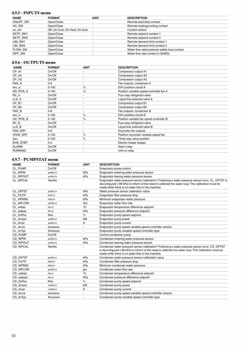
4.9.5 - INPUTS menuNAME FORMAT UNIT DESCRIPTIONONOFF_SW Open/Close - Remote start/stop contactHC_SW Open/Close - Remote heating/cooling contacton_ctrl Off, On Cool, On Heat, On Auto - Current controlSETP_SW1 Open/Close - Remote setpoint contact 1SETP_SW2 Open/Close - Remote setpoint contact 2LIM_SW1 Open/Close - Remote demand limit contact 1LIM_SW2 Open/Close - Remote demand limit contact 2FLOW_SW Open/Close - Water flow rate/customer safety loop contactDIFF_SW Open/Close - Water flow rate contact 2 (30WG)
4.9.6 - OUTPUTS menu NAME FORMAT UNIT DESCRIPTIONCP_A1 On/Off - Compressor output A1CP_A2 On/Off - Compressor output A2CP_A3 On/Off - Compressor output A3FAN_A 0-8 - Fan outputs, condenser Aexv_a 0-100 % EXV position circuit AHD_POS_A 0-100 % Position variable speed controller fan ARV_A On/Off - Four-way refrigerant valveLLS_A On/Off - Liquid line solenoid valve ACP_B1 On/Off - Compressor output B1CP_B2 On/Off - Compressor output B2FAN_B 0-8 - Fan outputs, condenser Bexv_b 0-100 % EXV position circuit BHD_POS_B 0-100 % Position variable fan speed controller BRV_B On/Off - Four-way refrigerant valveLLS_B On/Off - Liquid line solenoid valve BFAN_DRY 0-8 - Drycooler fan outputsVFAN_DRY 0-100 % Position drycooler variable speed fan3wv 0-100 % Three-way valve positionEHS_STEP 0-4 - Electric heater stagesALARM On/Off - Alarm relayRUNNING On/Off - Unit on relay
4.9.7 - PUMPSTAT menuNAME FORMAT UNIT DESCRIPTIONCL_PUMP On/Off - Evaporator pump controlCL_WPIN ±nnn.n kPa Evaporator entering water pressure sensorCL_WPOUT ±nnn.n kPa Evaporator leaving water pressure sensorCL_WPCAL Yes/No - Evaporator water pressure sensor calibration?.Following a water pressure sensor error, CL_OFFST is
deconfigured (-99 kPa) to inform of the need to calibrate the water loop. This calibration must be made while there is no water flow in the machine
CL_OFFST ±nnn.n kPa Water pressure sensor calibration valueCL_FILTR nnn.n kPa Evaporator filter pressure dropCL_WPMIN nnn.n kPa Minimum evaporator water pressureCL_WFLOW ±nnn.n G/s Evaporator water flow rateCL_wdtsp nn.n ^C Evaporator temperature difference setpointCL_wdpsp nn.n kPa Evaporator pressure difference setpointCL_DvPos Nnn % Evaporator pump speed setpointCL_drvpwr ±nnn.n kW Evaporator pump powerCL_drvpI ±nnn.n A Evaporator pump currentCL_drvvs xxxxxxxx - Evaporator pump speed variable speed controller versionCL_dvTyp Xxxxxxxx - Evaporator pump variable speed controller typeCD_PUMP On/Off - Control condenser pumpCD_WPIN ±nnn.n kPa Condenser entering water pressure sensorCD_WPOUT ±nnn.n kPa Condenser leaving water pressure sensorCD_WPCAL Yes/No - Condenser water pressure sensor calibration? Following a water pressure sensor error, CD_OFFST
is deconfigured (-99 kPa) to inform of the need to calibrate the water loop. This calibration must be made while there is no water flow in the machine
CD_OFFST ±nnn.n kPa Condenser water pressure sensor calibration valueCD_FILTR nnn.n kPa Condenser filter pressure dropCD_WPMIN nnn.n kPa Minimum condenser water pressureCD_WFLOW ±nnn.n g/s Condenser water flow rateCD_wdtspt nn.n ^C Condenser temperature difference setpointCD_wdpspt nn.n kPa Condenser pressure difference setpointCD_DvPos Nnn % Condenser pump speed setpointCD_drvpwr +nnn.n kW Condenser pump powerCD_drvpl +nnn.n A Condenser pump currentCD_drvvs xxxxxxxx - Condenser pump speed variable speed controller versionCD_dvTyp Xxxxxxxx - Condenser pump variable speed controller type

11
4.9.8 – HDC_STAT menu NAME FORMAT UNIT DESCRIPTIONdhw_mode n - Mode (0 = heating, 1 = DHW, 2 = valve moving)dhw_dem No/Yes - DHW demanddhw_time nnn mn DHW mode operating timeshc_time nnn mn Heating mode operating timesum_mode No/Yes - Summer modectrl_pnt +-nnn.n °C Current setpointoat +-nnn.n °C Outside air temperatureDHW_REQ Open/Close - DHW demand volt-free contact (from the tank)DHW_SW Open/Close - DHW priority volt-free contactSUMM_SW Open/Close - Summer mode volt-free contactadd_pump Off/On - Additional pump outputdhw_vlv Off/On - DHW three-way valve outputehs n - Electric heater stages
4.9.9 - RUNTIME menuNAME FORMAT UNIT DESCRIPTIONhr_mach nnnnn hours Unit operating hourschr_mach nnnnn hours Unit operating hours in cooling modehhr_mach nnnnn hours Unit operating hours in heating modest_mach nnnnn - Number of start-ups, unitHR_CP_A1 nnnnn hours Operating hours compressor A1st_cp_a1 nnnnn - Number of start-ups compressor A1HR_CP_A2 nnnnn hours Operating hours compressor A2st_cp_a2 nnnnn - Number of start-ups compressor A2HR_CP_A3 nnnnn hours Operating hours compressor A3st_cp_a3 nnnnn - Number of start-ups compressor A3HR_CP_B1 nnnnn hours Operating hours compressor B1st_cp_b1 nnnnn - Number of start-ups compressor B1HR_CP_B2 nnnnn hours Operating hours compressor B2st_cp_b2 nnnnn - Number of start-ups compressor B2hr_clpmp nnnnn hours Operating hours evaporator pumphr_cdpmp nnnnn hours Operating hours condenser pumpHr_olpmp nnnnn - Operating hours open-loop pumphr_ehs nnnnn - Operating hours electric heater stageshr_hdpmp nnnnn hours Operating hours HDC module pump
4.9.10 - MODES menuNAME FORMAT UNIT DESCRIPTIONm_limit Yes/No - Demand limit activem_ramp Yes/No - Ramp loading activem_night Yes/No - Low-noise level night modem_SM Yes/No - Aquasmart activem_leadla Yes/No - Master/slave activem_auto Yes/No - Changeover activem_heater Yes/No - Electric heater stages activem_lo_ewt Yes/No - Lock heating mode and entering water too coldm_boiler Yes/No - Boiler activem_sst_a Yes/No - Low suction temperature circuit Am_sst_b Yes/No - Low suction temperature circuit Bm_dgt_a Yes/No - High discharge gas temperature circuit Am_dgt_b Yes/No - High discharge gas temperature circuit Bm_hp_a Yes/No - High pressure circuit Am_hp_b Yes/No - High pressure circuit Bm_sh_a Yes/No - Low superheat circuit Am_sh_b Yes/No - Low superheat circuit Bm_dhw Yes/No - Domestic hot water modem_summer Yes/No - Summer mode
4.9.11 - ALARMS menuNAME DESCRIPTIONALARMRST Alarm resetCUR_ALRM Current alarmsALMHIST1 Alarm history

12
4.9.12 - CONFIG menuNAME DESCRIPTIONGEN_CONF General configuration menuPUMPCONF Water pump configuration menuHC_CONFIG Heating/cooling configuration menuHDC_CONF Heating module configuration menuRESETCFG Reset configuration menuUSERCONFIG User configuration menuSCHEDULE Time scheduleHOLIDAY Holiday calendarBRODCAST Broadcast menuDATETIME Date and time menuDISPLAY Display configuration menuCTRL_ID Identification control
4.9.13 - ALARMRST menuNAME FORMAT UNIT DESCRIPTIONRESET_AL Normal - Alarm reset ALM Normal - Alarm statusalarm_1c nnnnn - Current alarm 1alarm_2c nnnnn - Current alarm 2alarm_3c nnnnn - Current alarm 3alarm_4c nnnnn - Current alarm 4alarm_5c nnnnn - Current alarm 5alarm_1 nnnnn - Current JBus alarm 1alarm_2 nnnnn - Current JBus alarm 2alarm_3 nnnnn - Current JBus alarm 3alarm_4 nnnnn - Current JBus alarm 4alarm_5 nnnnn - Current JBus alarm 5
4.9.14 - CUR_ALRM menuThis menu lists up to ten a active alarms. For each alarm the display shows the time and date the alarm was generated as well as the alarm description. Each screen shows one alarm.
…\ALARMS\CUR_ALM
HH:MM DD-MM-YY: alarm text
Alarm #1
4.9.15 - ALMHIST1 menuThis menu lists up to twenty alarms that have occurred at the unit. For each alarm the display shows the time and date the alarm was generated as well as the alarm description. Each screen shows one alarm.
…\ALARMS\ALMHIST1
HH:MM DD-MM-YY: alarm text
Alarm #1
4.9.16 - SCHEDULE menuNAME DESCRIPTIONOCC1P01S Unit on/off time scheduleOCC1P02S Unit setpoint selection time scheduleOCC3P03S Domestic hot water time schedule
4.9.17 - HOLIDAY menuNAME DESCRIPTIONHOLDY_01 Holiday period 1HOLDY_02 Holiday period 2HOLDY_03 Holiday period 3HOLDY_04 Holiday period 4HOLDY_05 Holiday period 5HOLDY_06 Holiday period 6HOLDY_07 Holiday period 7HOLDY_08 Holiday period 8HOLDY_09 Holiday period 9HOLDY_10 Holiday period 10HOLDY_11 Holiday period 11HOLDY_12 Holiday period 12HOLDY_13 Holiday period 13HOLDY_14 Holiday period 14HOLDY_15 Holiday period 15HOLDY_16 Holiday period 16

13
4.9.18 - BRODCAST menu NAME FORMAT DEFAULT UNIT DESCRIPTIONccnbroad 0/1/2 2 - Activates the broadcast
0 = deactivated, 1= broadast during holidays at the network, 2 = broadcast during holidays, machine only
oatbusnm 0 to 239 0 - Broadcast of the outside temperature Bus number of the machine with the outside temperature
oatlocad 0 to 239 0 - Element number of the machine with the outside temperaturedayl_sel Disable/Enable Disable - Activation summer time, winter timeSummer timestartmon 1 to 12 3 - Monthstartdow 1 to 7 7 - Day of the week (1 = Monday)startwom 1 to 5 5 - Week of the monthWinter timestopmon 1 to 12 10 - Monthstoptdow 1 to 7 7 - Day of the week (1 = Monday)stopwom 1 to 5 5 - Week of the month
4.9.19 - GENCONF menuNAME FORMAT DEFAULT UNIT DESCRIPTIONlead_cir 0/1/2 0 - Circuit loading sequence
0 = auto, 1 = A first, 2 = B firstseq_typ No/Yes No - Loading sequence by circuitramp_sel No/Yes No - Ramp loading sequenceoff_on_d 1 to 15 1 min Start-up delay nh_limit 0 to 100 100 % Capacity limitation in night modenh_start 00:00 to 24:00 00:00 - Night mode start hournh_end 00:00 to 24:00 00:00 - Night mode stop hourbas_menu 0 to 3 0 - Basic menu configuration
0 = total access1 = access to the alarm menu by password2 = access to the setpoint menu by password 3 = combination of 1 and 2
synoptic No/Yes No - Synoptic diagram displayed
4.9.20 - PUMPCONF menuNAME FORMAT DEFAULT UNIT DESCRIPTIONclpmpseq No/Yes No - Evaporator pump selectionclpmpper No/Yes No - Evaporator pump seizure protectionclpmpsby No/Yes No - Pump shutdown when the unit is in standbyclpmploc No/Yes Yes - Flow rate verification when the pump has shut downcdpmpseq No/Yes No - Condenser pump selectioncdpmpper No/Yes No - Condenser pump seizure protectioncdpmpsby No/Yes No - Pump shutdown when the unit is in standbycdpmploc No/Yes Yes - Flow rate verification when the pump has shut downol_pump No/Yes No Open-loop pump control selection
4.9.21 - HCCONFIG menuNAME FORMAT DEFAULT UNIT DESCRIPTIONauto_sel No/Yes No - Automatic changeover selectioncr_sel 0 to 2 0 - Cooling reset selectionhr_sel 0 to 2 0 - Heating reset selection
1 = outside temp., 0 = none, 2 = delta Theat_th -20 to 0 -15 °C Outside temperature threshold cooling modeboil_sel No/Yes No - Boiler control selectionboil_th -15 to 15 -10 °C Outside temperature threshold for the boilerehs_sel 0 to 4 0 - Selection, number of electric heater stagesehs_th -5 to 21.2 5 °C Outside temperature threshold for electric heater stagesboth_sel No/Yes No - Heating or cooling command selection for HSMehs_back No/Yes No - 1 backup electric heater stageehs_pull 0 to 60 0 minutes Delay before start-up of the first electric heater stageehs_defr No/Yes No - Quick electric heat stages for defrost
4.9.22 - HDC_CONF menuNAME FORMAT DEFAULT UNIT DESCRIPTIONadpmpper Yes/No Yes - Additional pump anti-stick functionsumm_oat 15.0 to 30.0 20.0 °C Outside air temperature threshold for the modeSummersumm_on 0 to 12 5 hours Time before changeover to summer modesumm_off 0 to 12 5 hours Time before changeover to winter modeshc_min 0 to 720 30 minutes Minimum duration in heating modeshc_max -1 to 720 * 180 minutes Maximum duration in heating modedhw_min 0 to 720 30 minutes Minimum duration in DHW modedhw_max -1 to 720 * 180 minutes Maximum duration in DHW mode
* -1 means that the maximum value is ignored

14
4.9.23 - RESETCFG menuNAME FORMAT DEFAULT UNIT DESCRIPTIONCOOLING RESEToatcr_no -10 to 51.7 -10 °C Outside temperature for no resetoatcr_fu -10 to 51.7 -10 °C Outside temperature for maximum resetdt_cr_no 0 to 13.9 0 ^C Delta T for no resetdt_cr_fu 0 to 13.9 0 ^C Delta T for maximum resetcr_deg -16.7 to 16.7 0 ^C Cooling reset valueHEATING RESEToathr_no -10 to 51.7 -10 °C Outside temperature for no resetoathr_fu -10 to 51.7 -10 °C Outside temperature for maximum resetdt_hr_no 0 to 13.9 0 ^C Delta T for no resetdt_hr_fu 0 to 13.9 0 ^C Delta T for maximum resethr_deg -16.7 to 16.7 0 ^C Heating reset value
4.9.24 - USERCONF menuNAME FORMAT DEFAULT UNIT DESCRIPTIONlanguage 0 to 4 0 - Language selection
English = 0, Spanish = 1, French = 2, Portuguese = 3, Italian = 4, Translation = 5
use_pass 1 to 9999 11 - User password
4.9.25 - DATETIME menuNAME FORMAT DEFAULT UNIT DESCRIPTIONhour 0 to 24 hours Hourminutes 0 to 59 minutes Minutesdow 1 to 7 Day of the weektom_hol No/Yes No - Holiday tomorrow?tod_hol No/Yes No - Holiday todaydlig_off No/Yes - Winter time changeover active?dlig_on No/Yes - Summer time changeover active?d_of_m 1 to 31 Day of the monthmonth 1 to 12 Monthyear 0 to 99 Year
4.9.26 - Menu CTRL_IDNAME FORMAT DEFAULT UNIT DESCRIPTIONelemt_nb 1 to 239 1 - Element numberbus_nb 0 to 239 0 - Bus numberbaudrate 9600 to 38400 9600 - Communication speed
PRO-DIALOG + 30WG DescriptionCSA-SR-20H450NN -
Software versionSerial number
4.9.27 - OCCx P0xS menuThe control provides three timer programs: schedule 1, schedule 2 and schedule 3, that can be activated.
The first timer program (schedule 1) provides a means to automatically switch the unit from an occupied mode to an unoccupied mode: the unit is started during occupied periods.
The second timer program (schedule 2) provides a means to automatically switch the active setpoint from an occupied setpoint to an unoccupied setpoint: cooling setpoint 1 is used during occupied periods, cooling or heating setpoint 2 during unoccupied periods.
The third timer program (schedule 3) allows the unit to switch to the domestic hot water production mode. The DHW mode is allowed during occupied periods.
Each schedule consists of eight time periods set by the operator. These time periods can be flagged to be in effect or not in effect on each day of the week plus a holiday period. The day begins at 00.00 hours and ends at 23.59 hours.
Program is in unoccupied mode unless a schedule time period is in effect. If two periods overlap and are both active on the same day, the occupied mode takes priority over the unoccupied period.
Each of the eight periods can be displayed and changed with the aid of a sub-sub-menu. The table on page 15 shows how to access the period configuration. Method is the same for the time schedule 1 or the time schedule 2.

15
Time schedule type:
232221
P6P320P319P318P3P2P217
P4P4P3P2P216P4P4P3P2P215P4P4P3P2P214P4P4P3P2P213P4P4P3P2P212
P5P4P4P3P2P211P5P4P4P3P2P210P5P4P4P3P2P29P5P4P4P3P2P28P5P4P4P3P2P27
6543
P12P11P10
HOLSUNSATFRITHUWESTUEMONTime MON: Monday
TUE: Tuesday
WED: Wednesday
THU: Thursday
FRI: Friday
SAT: Saturday
SUN: Sunday
HOL: Holiday
OccupiedUnoccupied
Starts at Stops at Active onP1: period 1, 0h00, 3h00, MondayP2: period 2, 7h00, 18h00, Monday + TuesdayP3: period 3, 7h00, 21h00, WednesdayP4: period 4, 7h00, 17h00, Thursday + FridayP5: period 5, 7h00, 12h00, SaturdayP6: period 6, 20h00, 21h00, HolidaysP7: period 7, Not used in this exampleP8: period 8, Not used in this example
NAME FORMAT DEFAULT UNIT DESCRIPTIONOVR_EXT 0-4 0 hours Occupied schedule overrideDOW1 0/1 11111111 - Period 1 day of the week MTWTFSSH
Monday Tuesday Wednesday Thursday Friday Saturday Sunday HolidayOCCTOD1 0:00-24:00 00:00 - Occupied from UNOCTOD1 0:00-24:00 24:00:00 - Occupied untilDOW2 0/1 0 - Period 2 days of the week MTWTFSSH
Monday Tuesday Wednesday Thursday Friday Saturday Sunday HolidayOCCTOD2 0:00-24:00 00:00 - Occupied from UNOCTOD2 0:00-24:00 00:00 - Occupied untilDOW3 0/1 0 - Period 3 days of the week MTWTFSSH
Monday Tuesday Wednesday Thursday Friday Saturday Sunday HolidayOCCTOD3 0:00-24:00 00:00 - Occupied from UNOCTOD3 0:00-24:00 00:00 - Occupied untilDOW4 0/1 0 - Period 4 days of the week MTWTFSSH
Monday Tuesday Wednesday Thursday Friday Saturday Sunday HolidayOCCTOD4 0:00-24:00 00:00 - Occupied from UNOCTOD4 0:00-24:00 00:00 - Occupied untilDOW5 0/1 0 - Period 5 days of the week MTWTFSSH
Monday Tuesday Wednesday Thursday Friday Saturday Sunday HolidayOCCTOD5 0:00-24:00 00:00 - Occupied from UNOCTOD5 0:00-24:00 00:00 - Occupied untilDOW6 0/1 0 - Period 6 days of the week MTWTFSSH
Monday Tuesday Wednesday Thursday Friday Saturday Sunday HolidayOCCTOD6 0:00-24:00 00:00 - Occupied from UNOCTOD6 0:00-24:00 00:00 - Occupied untilDOW7 0/1 0 - Period 7 days of the week MTWTFSSH
Monday Tuesday Wednesday Thursday Friday Saturday Sunday HolidayOCCTOD7 0:00-24:00 00:00 - Occupied from UNOCTOD7 0:00-24:00 00:00 - Occupied untilDOW8 0/1 0 - Period 8 days of the week MTWTFSSH
Monday Tuesday Wednesday Thursday Friday Saturday Sunday HolidayOCCTOD8 0:00-24:00 00:00 - Occupied from UNOCTOD8 0:00-24:00 00:00 - Occupied until
4.9.28 - HOLIDY0XS menuThis function is used to define 16 public holiday periods. Each period is defined with the aid of three parameters: the month, starting day and duration of the public holiday period. During these public holidays the controller will be in occupied or unoccupied mode, depending on the programmed periods validated for public holidays.
Each of these public holiday periods can be displayed and changed with the aid of a sub-menu.
ATTENTION: The broadcast function must be activated to utilise the holiday schedule, even if the unit is running in stand-alone mode (not connected to CCN).
NAME FORMAT DEFAULT UNIT DESCRIPTIONHOL_MON 0-12 0 - Holiday monthHOL_DAY 0-31 0 - Holiday dayHOL_LEN 0-99 0 - Holiday duration

16
5 - PRO-DIALOG+ CONTROL OPERATION
5.1 - Start/stop control
The table below summarises the unit control type and stop or go status with regard to the following parameters.• Operating type: this is selected using the start/stop
button on the front of the user interface. LOFF: local off, L-C: local on, L-SC: local schedule,
REM: remote, CCN: network, MAST: Master• Remote start/stop contacts: these contacts are used
when the unit is in remote operating type (Remote). See sections 3.6.2 and 3.6.3.
• CHIL_S_S: this network command relates to the unit start/stop when the unit is in network mode (CCN).
• Command set to Stop: the unit is halted. • Command set to Start: the unit runs in accordance
with schedule 1.• Start/Stop schedule: occupied or unoccupied status of
the unit as determined by the chiller start/stop program (Schedule 1).
• Master control type. This parameter is used when the unit is the master unit in a two chiller lead/lag arrange-ment. The master control type determines whether the unit is to be controlled locally, remotely or through CCN (this parameter is a Service configuration).
• CCN emergency shutdown: if this CCN command is activated, it shuts the unit down whatever the active operating type.
• General alarm: the unit is totally stopped due to failure.
5.2 - Heating/cooling/standby operation
5.2.1 - GeneralThe heating/cooling/standby selection applies to all units. It can be done manually (or automatically on a unit with outside air temperature sensor).
In automatic mode the outdoor temperature determines the heating/cooling/standby changeover based on the two threshold values configured by the user (see RESETCFG menu).
If the unit is in standby it does not cool or heat, and no compressor can be activated. The diagram below summarises the operating principle in automatic mode.
HEATING STANDBY COOLINGOutdoor temperature
Heating threshold*
Cooling threshold
* This threshold does not apply to cooling only units that do not control a boiler.
ACTIVE OPERATING TYPE STATUS OF PARAMETERS CONTROL TYPE
UNIT MODE
LOFF L-ON L-SC rEM CCN MASt CHIL_S_S REMOTE START/STOP CONTACT
MASTER CONTROL TYPE
START/STOP SCHEDULE MODE
CCN EMERGENCY SHUTDOWN
GENERAL ALARM
- - - - - - - - - - Enable - - Off- - - - - - - - - - - Yes - OffActive - - - - - - - - - - - Local Off- - Active - - - - - - Unoccupied - - Local Off- - - Active - - - Off - - - - Remote Off- - - Active - - - - - Unoccupied - - Remote Off- - - - Active - Disable - - - - - CCN Off- - - - Active - - - - Unoccupied - - CCN Off- - - - - Active - - Local Unoccupied - - Local Off- - - - - Active - Off Remote - - - Remote Off- - - - - Active - - Remote Unoccupied - - Remote Off- - - - - Active Disable - CCN - - - CCN Off- - - - - Active - - CCN Unoccupied - - CCN Off- Active - - - - - - - - Disable No Local On- - Active - - - - - - Occupied Disable No Local On- - - Active - - - On cooling - Occupied Disable No Remote On- - - Active - - - On heating - Occupied Disable No Remote On- - - Active - - - On auto - Occupied Disable No Remote On- - - - Active - Enable - - Occupied Disable No CCN On- - - - - Active - - Local Occupied Disable No Local On- - - - - Active - On cooling Remote Occupied Disable No Remote On- - - - - Active - On heating Remote Occupied Disable No Remote On- - - - - Active - On auto Remote Occupied Disable No Remote On- - - - - Active Enable - CCN Occupied Disable No CCN On

17
5.3 - Heat exchanger water pump control
The unit can control one water pump per heat exchanger. The pump is turned on when this option is configured (see PUMPCONFIG) and when the unit is in one of the on modes described above or in delay mode. Since the minimum value for the delay at start-up is 1 minute (configurable between 1 and 15 minutes), the pump will run for at least one minute before the first compressor starts.
The pump is kept running for 2 minutes after the unit goes to stop mode. The pump keeps working when the unit switches from heating to cooling mode or vice-versa. It is turned off if the unit is shut down due to an alarm unless the fault is a frost protection error. The pump can be started in particular operating conditions when frost protection of the heat exchanger is active (see chapter “Control point”). See chapter “Master/slave assembly” for the particular heat exchanger pump control for the slave unit (master/slave assembly).
If the pump with variable flow option has been selected (factory-installed option), it is possible to control the water flow in three ways (service parameters):• adjusted fixed flow rate,• constant temperature difference,• constant pressure difference.
In this way it is possible to adjust the water loops and to optimise pump operation.
The control provides a means to automatically start the pump each day at 14.00 hours for 2 seconds when the unit is off (pump anti-stick function). Starting the pump periodically for few seconds increases the life-time of the pump bearings and the tightness of the pump seal.
5.4 - Control interlock contact
This contact checks the status of a loop (water flow switch and customer safety loop, see chapter 3.6). It prevents the unit from starting if it is open when the delay at start-up has expired. This open contact leads to an alarm shut-down, if the unit is running.
5.5 - Control point
The control point represents the water temperature that the unit must produce. The heat exchanger entering water temperature is controlled by default, but the heat exchanger leaving water temperature can also be controlled (requires a Service configuration modification).
Control point = active setpoint + reset
5.5.1 - Active setpointThree setpoints can be selected as active in cooling mode and two in heating mode. Usually, the second setpoint is used for unoccupied periods.
Depending on the current operating type, the active setpoint can be selected:• by choosing the item in the GENUNIT menu,• via the user’s volt-free contacts,• via network commands• via the setpoint timer program (schedule 2).
5.2.2 - Heating/cooling/auto selectionThe table below summarises the unit heating/cooling opera-tion, based on the following parameters:• Control type: indicates whether the unit operates in
local, remote or CCN mode. See section 5.1.• Unit on/off status: indicates whether the unit is shut
down (not authorised to start) or in operation (or authorised to start).
• Heating/cooling/auto selection in local mode: operating mode selected via the user interface. See GENUNIT menu.
• Remote heating/cooling contacts: these contacts are only active if the unit is under remote control.
• HC_SEL: this network command permits heating/cooling/auto control, if the unit is in CCN operating mode.
• Outside temperature: determines the operation, if the unit is in automatic heating/cooling/standby changeover mode.
PARAMETER STATUSON/OFF STATUS CONTROL TYPE HEATING/COOLING
SELECTION IN LOCAL MODE
REMOTE HEATING/COOLING CONTACTS
HC_SEL OUTDOOR TEMPERATURE OPERATING MODE
Off - - - - - CoolingOn Local Cooling - - - CoolingOn Local Heating - - - HeatingOn Local Auto - - > Cooling threshold CoolingOn Local Auto - - < Heating threshold Heating*On Local Auto - - Between cooling and heating thresholds StandbyOn Remote - Cooling mode - - CoolingOn Remote - Heating mode - - HeatingOn Remote - Auto mode - > Cooling threshold CoolingOn Remote - Auto mode - < Heating threshold Heating*On Remote - Auto mode - Between cooling and heating thresholds StandbyOn CCN - - Cooling - CoolingOn CCN - - Heating - HeatingOn CCN - - Auto > Cooling threshold CoolingOn CCN - - Auto < Heating threshold Heating*On CCN - - Auto Between cooling and heating thresholds Standby* Does not apply to cooling only units that do not control a boiler.

18
The following tables summarise the possible selections depending on the control types (local, remote or network) and the following parameters:• Setpoint select in local control: item LSP_SEL in the
GENUNIT menu permits selection of the active set-point, if the unit is in local operating type.
• Heating/cooling operating mode.• Setpoint selection contacts: setpoint selection contact
status.• Schedule 2 status: schedule for setpoint selection.
LOCAL OPERATING MODEPARAMETER STATUSHeating/cooling operating mode
Local setpoint selection
Time schedule 2 status
Active setpoint
Cooling sp 1 - Cooling setpoint 1Cooling sp 2 - Cooling setpoint 2Cooling Ice_sp - Ice storage cooling
setpointCooling auto occupied Cooling setpoint 1Cooling auto unoccupied Cooling setpoint 2Heating sp1 - Heating setpoint 1Heating sp 2 - Heating setpoint 2Heating sp 3 - Heating setpoint 3Heating auto occupied Heating setpoint 1Heating auto unoccupied Heating setpoint 2
REMOTE OPERATING MODEPARAMETER STATUSHeating/cooling operating mode
Setpoint selection contact
Active setpoint
Cooling sp 1 (open) Cooling setpoint 1 Cooling sp 2 (closed) Cooling setpoint 2Heating sp 1 (open) Heating setpoint 1Heating sp 2 (closed) Heating setpoint 2
Reset example in cooling mode based on the outside temperature
LegendA Maximum reset valueB OAT or delta T for no resetC OAT or delta T for full resetD Building Load
5.6 - Capacity control
This function adjusts the number of active compressors to keep the heat exchanger water temperature at its setpoint. The precision with which this is achieved depends on the capacity of the water loop, the flow rate, the load, and the number of stages available on the unit. The control system continuously takes account of the temperature error with respect to the setpoint, as well as the rate of change in this error and the difference between entering and leaving water temperatures, in order to determine the optimum moment at which to add or withdraw a capacity stage.
If the same compressor undergoes too many starts (per hour) or runs below one minute each time it is started this automatically brings about reduction of compressor starts, which makes leaving water temperature control less precise.
The high pressure, low pressure or defrost unloading func-tions can also affect temperature control accuracy. Compres-sors are started and stopped in a sequence designed to equalise the number of start-ups (value weighted by their operating time).
5.7 - Demand limit
The demand limit is used to restrict the unit power consumption. The Pro-Dialog control system allows limitation of the unit capacity, using user-controlled volt-free contacts.
The unit capacity can never exceed the limit setpoint activated by these contacts. The limit setpoints can be modified in the SETPOINT menu.
5.8 - Night mode
The night period is defined (see GENUNIT configuration) by a start time and an end time that are the same for each day of the week. During the night period the unit capacity may be limited.
Rese
t val
ue
Outdoor temperature (OAT)Heat exchanger delta T
% B
uild
ing
load
5.5.2 - ResetReset means that the active setpoint is modified so that the machine capacity required is adjusted to be as close as possible to the demand. This modification is in general a reaction to a drop in the load. For the Pro-Dialog control system, the source of the reset can be configured in the HCCONFIG configuration: it can be provided either by the outdoor temperature (that gives a measure of the load trends for the building) or by the return water temperature (heat exchanger delta T, gives an average building load).
In response to a drop in the outdoor temperature or to a drop in delta T, the cooling setpoint is normally reset upwards in order to optimise unit performance:
In both cases the reset parameters, i.e. slope, source and maximum value, are configurable in the RESETCFG menu (see section 4.3.8). Reset is a linear function based on three parameters.• A reference at which reset is zero (outdoor temperature
or delta T - no reset value).• A reference at which reset is maximum (outdoor
temperature or delta T - full reset value).• The maximum reset value.

19
5.9 - Control of a boiler
NOTE: The control of the electric heating stages or of a boiler is not authorised for slave units.
The unit can control the start-up of a boiler, if it is in heating mode. When the boiler is operating, the unit water pump is stopped.
The unit and a boiler cannot operate together. In this case the boiler output is activated in the following conditions:• The unit is in heating mode, but a fault prevents the
use of the heat pump capacity.• The unit is in heating mode, but works at a very low
outdoor temperature, making the heat pump capacity insufficient. It is possible to adjust the boiler start-up based on the outside temperature (HCCONFIG menu).
5.10 - Master/slave assembly
Two Pro-Dialog+ units can be linked to produce a master/slave assembly. The two machines are interconnected over the CCN bus. All parameters required for the master/slave function must be configured through the Service configura-tion menu.
Master/slave operation requires the connection of a tempe-rature probe at the common manifold on each machine, if the heat exchanger leaving water temperature is controlled. It is not required, if the entering water temperature is controlled.
The master/slave assembly can operate with constant or variable flow. In the case of variable flow each machine must control its own water pump and automatically shut down the pump, if the cooling capacity is zero.
For constant flow operation the pumps for each unit are continuously operating, if the system is operating. The master unit can control a common pump that will be activated, when the system is started. In this case the slave unit pump is not used.
All control commands to the master/slave assembly (start/stop, setpoint, heating/cooling operation, load shedding, etc.) are handled by the unit which is configured as the master, and must therefore only be applied to the master unit. They will be transmitted automatically to the slave unit.
The master unit can be controlled locally, remotely or by CCN com-mands. Therefore to start up the assembly, simply validate the Master operating type (Master) on the master unit. If the Master has been configured for remote control then use the remote volt-free contacts for unit start/stop.
The slave unit must stay in CCN operating type continuously. To stop the master/slave assembly, select Local Off on the master unit or use the remote volt-free contacts if the unit has been configured for remote control.
One of the functions of the master unit (depending on its configuration) may be the designation, whether the master or slave is to be the lead machine or the follower. The roles of lead machine and follower will be reversed when the difference in running hours between the two units exceeds a configurable value, ensuring that the running times of the two units are automatically equalised.
The changeover between lead machine and follower may take place when the assembly is started up, or even whilst running. The running time balancing function is not active if it has not been configured: in this case the lead machine is always the master unit.
The lead machine will always be started first. When the lead machine is at its full available capacity, start-up delay (configurable) is initialised on the follower. When this delay has expired, and if the error on the control point is greater than 1.7°C, the follower unit is authorised to start and the pump is activated. The follower will automatically use the master unit active setpoint. The lead machine will be held at its full available capacity for as long as the active capacity on the follower is not zero. When the follower unit receives a command to stop, its evaporator water pump is turned off with 20 seconds delay.
In the event of a communication fault between the two units, each shall return to an autonomous operating mode until the fault is cleared. If the master unit is halted due to an alarm, the slave unit is authorised to start without prior conditions.
ATTENTION: For heat pumps operating in master/slave mode and using an NRCP2 board or equipped with electric heater stages control must be on the entering water temperature.
5.11 - Heating module (HDC) control
61WG units are specially designed to optimise the operation of heating installations that require hot-water production for traditional heating and domestic hot water (DHW) requirements.
In this case an AUX board is included in the unit control box.
The Pro-Dialog+ control of the 61WG includes algorithms that permit constant and automatic optimisation:• control of a three-way directional on/off valve based
on the heating or domestic hot water requirements• control of the electric heater stages can complement
the heating loop• hot water setpoint reset (heating application) based
on the outside air temperature• priority control between heating and domestic hot
water applications.
5.11.1 – SensorAn optional outside air temperatrure sensor can be used to reset the setpoint or determine the summer/winter mode.

20
5.11.2 – ControlsThe heating module controls the following elements:• A three-way valve to switch over to domestic hot
water production• An additional water pump in the heating circuit• Up to four electric heating stages (for supplementary
safety stage heating)
5.11.3 – User connection terminalsThree volt-free contacts are available at a user connection terminal board: • A contact for DHW demand from the tank• A volt-free contact for DHW priority• A volt-free contact for the summer mode
5.11.4 – Control of additional electric heater stagesThe heat pump units can control up to four electric heater stages as supplementary heating.
Electric heater stages are activated to supplement the heating capacity if the following conditions are satisfied:• The unit uses 100% of its available heating capacity or
the unit is limited in its operation by a protection mode (e.g. low suction temperature protection) and in all cases cannot satisfy the heating demand.
• The outside temperature is below a configurable threshold (see HCCONFIG menu)
• Unit demand limitation is not active.
If required the user can configure the last electric heater stage available as a safety stage. That safety stage is only activated in addition to the other stages, if there is a unit fault that prevents the use of the heating capacity. The other electric heater stages continue to operate a described above.
The electric heater stages only operate in the heating mode, but not during domestic hot water production.
5.11.5 – Heating or domestic hot waterA three-way valve permits switching the heating capacity to a heating circuit (fan coil units, radiators or floor heating), or to a domestic hot water tank.
The unit requests changeover to the domestic hot water mode if all the following conditions have been met:• The volt-free tank request contact is closed AND• Time schedule 3 is in an occupied period OR the
volt-free priority contact is closed.
Based on the operating mode the water setpoint is adjusted:• In heating mode, setpoints hsp1 and hsp2 are used.
They can be modified by user reset or based on the outside temperature.
• In domestic hot water production mode setpoint hsp3 is used. No setpoint reset is used.
The unit requests changeover to the heating mode, if at least one of the following conditions applies:• The volt-free tank request contact is open OR• The maximum operating duration in the DHW mode
has finished OR• Time schedule 3 is in an unoccupied period.
If a mode change is requested while a compressor is operat-ing, it is stopped before the three-way valve changes to the new mode, and then the unit is re-started.
If the unit is in domestic hot water production mode, a “DHW” message is displayed on the user interface next to the current operating mode. Example: “Local Running DHW”.
5.11.6 – Summer modeThe summer mode is activated when the outside temperature exceeds the parameter threshold summ_oat during the summ_on time. It is deactivated if the outside temperature returns to a lower value than the parameter threshold summ_oat during the summ_off time. The summer mode can also be activated if the volt-free contact SUMM_SW is closed.
5.11.7 – Additonal water pumpAn additional water pump, installed in the heating water circuit starts if the summer mode is deactivated. If the anti-stick function is configured, the additional water pump starts periodically.
5.12 - Condensing pressure control - 30WG unit in cooling modeThe control can regulate the following configurations:• Drycooler and variable-speed condenser pump. The fixed fan stages and the pump speed are controlled
to maintain a fixed condensing setpoint (value adjustable).
• Variable-speed condenser pump (without drycooler control).
The condenser pump integrated into the unit is controlled to maintain a fixed condensing setpoint (value adjustable).
• Drycooler and three-way valves. The fixed fan stages and the three-way valve position
are controlled to permit start-ups at low outside tempe-ratures and maintaining a fixed condensing setpoint (value adjustable).
• Three-way valve only (without drycooler control). The position of the three-way valve is controlled to
maintain a fixed condensing setpoint (value adjustable).• Drycooler only (fixed or variable speed). Only the drycooler fan stages are controlled by refe-
rence to a fixed drycooler water outlet (value adjustable).
The condensing setpoint is adjustable with item cond_sp in the SETPOINT table (SETPOINT menu, chapter 4.9.4).The condensing setpoint can be reset by reference to the outside temperature to optimise the operation of the condensing system.
To set the condensing setpoint reset, the following adjust-ments are necessary:• item hr_sel = 2 (HCCONFIG menu, chapter 4.9.21), • items oathr_no, oathr_fu et hr_deg (RESETCFG menu,
chapter 4.9.23).

21
6 - DIAGNOSTICS - TROUBLESHOOTING
6.1 - General
The Pro-Dialog+ control system has many fault tracing aid functions. The local interface and its various menus give access to all unit operating conditions. If an operating fault is detected, an alarm is activated and an alarm code is stored in the Alarms menu, sub-menus CUR_ALRM and ALARMRST.
6.2 - Displaying alarms
The alarm LED on the interface (see chapter 4.1) allows the quick display of the unit status.• A flashing LED shows that the circuit is operating but
there is an alert.• A steady LED shows that the circuit has been shut
down due to a fault.
The ALARMRST menu on the main interface displays up to five fault codes that are active on the unit.
6.3 - Resetting alarms
When the cause of the alarm has been corrected the alarm can be reset, depending on the type, either automatically on return to normal, or manually when action has been taken on the unit. Alarms can be reset even if the unit is running.
This means that an alarm can be reset without stopping the machine. In the event of a power supply interrupt, the unit restarts automatically without the need for an external command. However, any faults active when the supply is interrupted are saved and may in certain cases prevent a circuit or a unit from restarting.
A manual reset must be run from the main interface via the ALARMRST menu, item RST_ALM. Depending on the configuration in the GENCONF menu, access to the item may be protected by a password.

22
6.4 - Alarm codes
Alarm No.
Alarm code
Alarm description Reset type Probable cause Action taken by the control
Thermistor faults1 th-01 Fluid sensor fault, evaporator water
outletAutomatic when the temperature measured by the sensor returns to normal
Defective thermistor Unit is shut down
2 th-02 Fluid sensor fault, evaporator water inlet
As above As above As above
3 th-06 Fluid sensor fault, condenser water outlet
Automatic when the temperature measured by the sensor returns to normal
Defective thermistor Unit is shut down
4 th-07 Fluid sensor fault, condenser water inlet
As above As above As above
5 th-10 Outside temperature sensor fault As above As above Unit is shut down6 th-11 HTWSTEMP fluid sensor fault
(master/slave)As above As above The master/slave mode is
stopped7 th-12 Suction sensor fault, circuit A As above As above Circuit is shut down8 th-13 Suction sensor fault, circuit B As above As above As above9 th-32 CHWSTEMP fluid sensor fault
(master/slave)As above As above The master/slave mode is
stopped10 th-36 Fluid sensor fault DRY_LWT As above As above Unit is shut down11 th-44 Sensor fault, discharge circuit A As above As above Circuit is shut down12 th-45 Sensor fault, discharge circuit B As above As above Circuit is shut downPressure transducer faults13 Pr-01 Discharge pressure transducer
fault, circuit AAutomatic when the voltage transmitted by the sensor returns to normal
Defective transducer or installation fault
Circuit is shut down
14 Pr-02 Discharge pressure transducer fault, circuit B
As above As above As above
15 Pr-04 Suction pressure transducer fault, circuit A
As above As above As above
16 Pr-05 Suction pressure transducer fault, circuit B
As above As above As above
17 Pr-24 Entering evaporator water pressure sensor fault
Automatic when the voltage transmitted by the sensor returns to normal
Defective transducer or installation fault
Circuit is shut down
18 Pr-25 Leaving evaporator water pressure sensor fault
Automatic when the voltage transmitted by the sensor returns to normal
Defective transducer or installation fault
Circuit is shut down
19 Pr-26 Entering condenser water pressure sensor fault
As above As above As above
20 Pr-27 Leaving condenser water pressure sensor fault
As above As above As above
Communication with the slave boards21 CO-BB Communication loss with the
NRCP2 boardAutomatic when communication is re-established
Installation bus fault or defective slave board
Depending on the configuration, compressor A3 is shut down or circuit B is shut down.
22 Co-e1 Communication loss with the EXV board
As above As above Unit is shut down
23 Co-o1 Communication loss with the PD-AUX 1 board
As above As above Unit with optional water pressure sensors, unit is shut down
24 Co-o2 Communication loss with the PD-AUX 2 board
As above As above Unit with optional water pressure sensors, unit is shut down
25 Co-o3 Communication loss with the PD-AUX 3 board
As above As above Unit with drycooler, unit is shut down
26 Co-o4 Communication loss with the PD-AUX 4 board
As above As above Unit with optional electric heater stages, unit is shut down
Process faults27 P-01 Water heat exchanger frost
protectionAutomatic if the same alarm has not tripped during the last 24 hours, otherwise manual.
Water flow rate too low or defective thermistor
Unit is shut down
28 P-05 Low suction temperature, circuit A Automatic when the temperature returns to normal, and if this alarm has not appeared during the last 24 hours, otherwise manual.
Pressure sensor defective, EXV blocked or low refrigerant charge
Circuit is shut down
29 P-06 Low suction temperature, circuit B As above As above As above30 P-08 High superheat, circuit A As above As above As above31 P-09 High superheat, circuit B As above As above As above32 P-11 Low superheat, circuit A As above As above As above33 P-12 Low superheat, circuit B As above As above As above34 P-14 Water flow control and customer
interlock faultAutomatic if the unit is in manual shut-down status, otherwise manual.
Heat exchanger pump defect or water flow switch fault
Unit is shut down
35 P-15 Condenser water flow control fault Automatic if the unit is in manual shut-down status, otherwise manual.
Heat exchanger pump defect or water flow switch fault
Unit is shut down
36 P-16 Compressor A1 not started or no pressure increase registered
Manual Connection problem Compressor is shut down
37 P-17 Compressor A2 not started or no pressure increase registered
As above As above As above
38 P-18 Compressor A3 not started or no pressure increase registered
As above As above As above
39 P-20 Compressor B1 not started or no pressure increase registered
As above As above As above
40 P-21 Compressor B2 not started or no pressure increase registered
As above As above As above
41 P-29 Communication loss with the System Manager
Automatic when communication is re-established
CCN installation bus defective Unit goes into autonomous mode

23
6.4 - Alarm codes (cont.)
Alarm No. Alarm code
Alarm description Reset type Probable cause Action taken by the control
Process faults (cont.)42 P-30 Communicaiton loss between
master and slaveAutomatic when communication is re-established
CCN installation bus defective Unit goes into autonomous mode
43 P-31 CCN emergency stop Manual Network command Circuit is shut down44 P-37 Repeated high-pressure unloading,
circuit AAutomatic Transducer defective or fan circuit
faultNone
45 P-38 Repeated high-pressure unloading, circuit B
As above As above As above
46 P-40 Repeated low suction temperature unloading
Manual Pressure sensor defective or refrigerant charge too low
Circuit is shut down
47 P-41 Repeated low suction temperature unloading
As above As above As above
48 P-43 Temperature at heat exchanger too low, less than 10°C prevents unit start-up
Automatic if the temperature detected returns to normal or when the mode returns to cooling
Operating compressor protection out of range or pressure sensor fault
The unit cannot start
49 MC-nn Master chiller configuration error Automatic when the master configuration returns to normal or when the unit is no longer in master/slave mode
Master/slave configuration error Master/slave mode is stopped
50 FC-n0 No factory configuration Automatic when the configuration is entered
The unit size has not been configured
Unit is shut down
51 FC-01 Illegal factory configuration number Manual The unit size has been configured with the wrong value
As above
52 Sr-00 Maintenance service alert Manual The preventive maintenance date has passed
53 V3-xx Fault, variable evaporator water pump controller
Automatic Fault in the variable speed controller
Unit is shut down
54 V4-xx Fault, variable condenser water pump controller
As above As above As above
55 P62-2 Evaporator water loop control fault, missing sensor calibration
Automatic if the calibration is valid No calibration As above
P62-3 Water loop control fault, suction pressure too low
Automatic the first time, if the water system is supplied with water, the second time manual if it is the same day
Too little water in the system Unit is shut down
P62-4 Water loop control fault, water pump has not started
Manual Pump fault As above
P62-5 ReservedP62-6 Water loop control fault, water
pump overloadAutomatic Missing pressure head at the water
pumpUnit is shut down
P62-7 Water loop control fault, water flow rate fault
Manual Serious water leak, pump faulty Unit is shut down
P62-8 Water loop control fault, water pressure sensors mixed up
Automatic Sensors mixed up Unit is shut down
56 P61-2 Evaporator water loop control fault, missing sensor calibration
Automatic if the calibration is valid No calibration As above
P61-3 Water loop control fault, suction pressure too low
Automatic the first time, if the water system is supplied with water, the second time manual if it is the same day
Too little water in the system Unit is shut down
P61-4 Water loop control fault, water pump has not started
Manual Pump fault As above
P61-5 ReservedP61-6 Water loop control fault, water
pump overloadAutomatic Missing pressure head at the water
pumpUnit is shut down
P61-7 Water loop control fault, water flow rate fault
Manual Serious water leak, pump faulty Unit is shut down
P61-8 Water loop control fault, water pressure sensors mixed up
Automatic Sensors mixed up Unit is shut down
57 P-63 High pressure fault in circuit A Manual Fan fault Circuit is shut down 58 P-64 High pressure fault in circuit B As above As above As above59 P-97 Reversed evaporator entering/
leaving water sensorsManual Sensor defective, sensors reversed Unit is shut down
60 P-99 Reversed condenser entering/leaving water sensors
Manual Sensor defective, sensors reversed Unit is shut down

Order No. 16123-76, 02.2012. Supersedes order No.: New. Manufactured by: Carrier SCS, Montluel, France.Manufacturer reserves the right to change any product specification without notice. Printed in the European Union.


![[Shinobi] Claymore 090](https://static.fdocuments.us/doc/165x107/568c367a1a28ab02359831bd/shinobi-claymore-090.jpg)