
5I CHAPTER XI TURBOJTET-ENGINE STARTING … XI TURBOJTET-ENGINE STARTING AND ACCELERATION By David...
73
,fr S. •• • ••• • SS* S. 43 • • NACA EM E55G28 • • :. (OT LAL . . . . • • S S • S • •• • •• S S • . . . S ••• • S • S • • • . 05 •.• •• ••• . S S. •• • • . • 5I •• CHAPTER XI TURBOJTET-ENGINE STARTING AND ACCELERATION By David M. Straight and Richard J. McCafferty X678777 INTRODUCTION From considerations of safety and reliability in performance of gas-turbine air- craft, it is clear that engine starting and acceleration are of utmost importance. For this reason extensive efforts have been devoted to the investigation of the fac- tors involved in the starting and acceleration of engines. In chapter III it is shown that certain basic combustion requirements must be met before ignition can occur; consequently, the design and operation of an engine must be tailored to provide these basic requirements in the combustion zone of the engine, particularly in the vicinity of the ignition source. It is pointed out in chapter III that ignition by electrical discharges is aided by high pressure, high temperature, low gas velocity and turbulence, gaseous fuel-air mixture, proper mix- ture strength, and-an optimum spark. duration. The simultaneous achievement of all these requirements in an actual turbojet-engine combustor is obviously impossible, cd yet any attempt to satisfy as many requirements as possible will result in lower ignition energies, lower-weight ignition systems, and greater reliability. These factors together with size and cost considerations detertninè the acceptability of the final ignition system. It is further shown in chapter III that tlte problem of wall quenching affects engine starting. For example, the dimensions of the volume to be burned must be larger than the quenching distance at the lowest pressure and the most adverse fuel- air ratio encountered. This fact affects the design of cross-fire tubes between adjacent combustion chambers in a tubular-combustor turbojet engine. Only two chambers in these engines contain spark plugs; therefore, the flame must propa- gate through small connecting tubes between the chambers. The quenching studies indicate that if the cross-fire tubes are too narrow the flame will not propagate from one chamber to another. In order to better understand the role of the basic factors in actual engine operation, many investigations have been conducted in single combustors from gas- turbine engines and in full-scale engines in altitude tanks and in flight. The pur- pose of the present chapter is to discuss the results of such studies and, where possible, to interpret these results qualitatively in terms of the basic requirements reported in chapter III. The discussion parallels the three phases of turbojet en- gine starting: (1) Ignition of the fuel-air mixture (2) Propagation of flame throughout the combustion zone (3) Acceleration of the engine to operating speed EFFECT OF VARIABLES ON IGNITION IN TURBOJET ENGINES Turbojet engines are usually started by (1) Cranking or wlndmilling the compressor and turbine to provide air flow https://ntrs.nasa.gov/search.jsp?R=19670095384 2018-05-30T21:41:41+00:00Z
Transcript of 5I CHAPTER XI TURBOJTET-ENGINE STARTING … XI TURBOJTET-ENGINE STARTING AND ACCELERATION By David...

,fr
S. •• • ••• • SS* S. 43 • • NACA EM E55G28 • • :. (OT LAL . . . . • • S S • S • •• • •• S S • . . . S ••• • S • S • • • . 05 •.• •• ••• . S S. •• • • . •5I ••
CHAPTER XI
TURBOJTET-ENGINE STARTING AND ACCELERATION
By David M. Straight and Richard J. McCafferty
X678777 INTRODUCTION
From considerations of safety and reliability in performance of gas-turbine air-craft, it is clear that engine starting and acceleration are of utmost importance. For this reason extensive efforts have been devoted to the investigation of the fac-tors involved in the starting and acceleration of engines.
In chapter III it is shown that certain basic combustion requirements must be met before ignition can occur; consequently, the design and operation of an engine must be tailored to provide these basic requirements in the combustion zone of the engine, particularly in the vicinity of the ignition source. It is pointed out in chapter III that ignition by electrical discharges is aided by high pressure, high temperature, low gas velocity and turbulence, gaseous fuel-air mixture, proper mix-ture strength, and-an optimum spark. duration. The simultaneous achievement of all these requirements in an actual turbojet-engine combustor is obviously impossible,
cd yet any attempt to satisfy as many requirements as possible will result in lower ignition energies, lower-weight ignition systems, and greater reliability. These factors together with size and cost considerations detertninè the acceptability of the final ignition system.
It is further shown in chapter III that tlte problem of wall quenching affects engine starting. For example, the dimensions of the volume to be burned must be larger than the quenching distance at the lowest pressure and the most adverse fuel-air ratio encountered. This fact affects the design of cross-fire tubes between adjacent combustion chambers in a tubular-combustor turbojet engine. Only two chambers in these engines contain spark plugs; therefore, the flame must propa-gate through small connecting tubes between the chambers. The quenching studies indicate that if the cross-fire tubes are too narrow the flame will not propagate from one chamber to another.
In order to better understand the role of the basic factors in actual engine operation, many investigations have been conducted in single combustors from gas-turbine engines and in full-scale engines in altitude tanks and in flight. The pur-pose of the present chapter is to discuss the results of such studies and, where possible, to interpret these results qualitatively in terms of the basic requirements reported in chapter III. The discussion parallels the three phases of turbojet en-gine starting:
(1) Ignition of the fuel-air mixture
(2) Propagation of flame throughout the combustion zone
(3) Acceleration of the engine to operating speed
EFFECT OF VARIABLES ON IGNITION IN TURBOJET ENGINES
Turbojet engines are usually started by
(1) Cranking or wlndmilling the compressor and turbine to provide air flow
https://ntrs.nasa.gov/search.jsp?R=19670095384 2018-05-30T21:41:41+00:00Z

44• • • . • S
(2) Turn
•5• S • S S. I • I
S.. • Lng on
S. S S
S S. fl 501
• I S.. • .
irce
I.. • SI
• . .
S. S S • S S
• S •• an ignitic
S•
1FI1LL555
. . • NACA EM E55G28 • S •• S • • S S • S
5•5 •S •S• •S
(3) Spraying fuel into the combustor
After the engine is started, the rotating speed of the compressor and turbine is in-creased from cranking or windmilling speed to an idle speed by increasing the fuel flow. Following this initial acceleration, acceleration to higher engine speeds is necessary to provide thrust for take-off and altitude flight conditions.
The most difficult starting conditions are those encountered on the ground at low ambient temperatures and those found at high altitude. The need for easy start-ing on the ground at all temperatures is obvious. Starts at altitude are also re-quired after flame-outs, or occasionally, in the operation of multiengine aircraft, where all engines are not operated at all times. The following sections review the various factors involved in the starting of turbojet engines.
Engine Operating Variables
Both flight and tunnel tests on full-scale engines have shown that the ease of starting is controlled by altitude, flight speed, and engine speed. These engine operating variables can be related to combustor-inlet temperatures, pressures, and velocities; such relations are given in chapter X. This relation permits the study of ignition in single turbojet combustors operated in connected-duct facilities where these inlet variables plus fuel flows and temperatures can be controlled to simulate engine operating conditions. Successful ignition is defined as continued burning after the ignition source has been shut off. A maximum time of 30 seconds is often the limit allowed for ignition attempts. Typical apparatus and procedure for single-combustor ignition studies are described in references 1 to 3.
Full-scale engine altitude tests are conducted in large altitude chambers or wind tunnels and by flight tests. In altitude test facilities, flight operating con-ditions are simulated by controlling engine inlet and outlet pressures, and fuel and air inlet temperatures. Instrumentation is provided to indicate engine inlet and outlet pressures (simulating altitude and flight Mach number), engine speed, air flow, fuel flow, and pressures and temperatures at various stations in the engine including combustor-inlet conditions. The ignition procedure consists in setting the altitude and flight-speed pressure and temperature conditions and allowing the engine windinilling speed to stabilize. The ignitor is then turned on and the fuel throttle opened slowly until ignition is obtained. If ignition does not occur, the throttle is manipulated to vary fuel flow over a wide range in further attempts to obtain ignition. A maximum time limit (usually 20 to 45 sec) is allowed for igni-tion. Another method of feeding fuel is to allow only a fixed flow rate to exist upon opening the throttle. The value of this flow rate is varied for different ig-nition attempts for these automatic starts.
Operational and design requirements of full-scale turbojet engines necessarily influence the selection of parameters for presenting single-combustor ignition limits. Full-scale engines must be started without exceeding the maximum allowable turbine temperature; thus, minimum fuel flow for ignition is a useful parameter for indicating ignition limits. It is desirable to design engine accessory systems with minimum weight, size, and cost. Hence, the ignition-energy supply system should be light weight, which, in turn, means use of low ignition energies. Therefore, mini-mum ignition energy is also used as a parameter for indicating the altitude and flight-speed ignition limits of these engines. In addition, the minimum combustor-inlet pressure for ignition is a useful parameter for establishing the altitude ig-nition limit of single combustors when the ignition energy is constant.
Wt-
NACA RM E55G28 :: .' . : : : : :. • • • • . : • • •• • •• . . •. •.. •. ... ..: •. •. : : : :.. :.
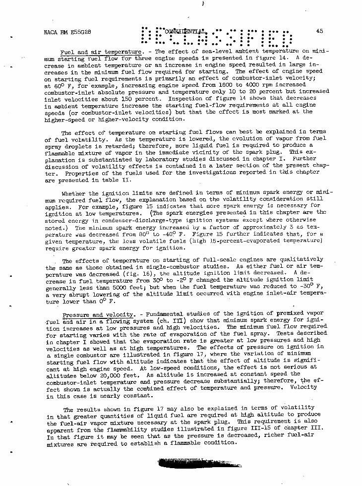
Fuel and air temperature. - The effect of sea-level ambient temperature on mini-mum starting fuel flow for three engine speeds is presented in figure 14. A de-crease in ambient temperature or an increase in engine speed resulted in large in-creases in the minimum fuel flow required for starting. The effect of engine speed on starting fuel requirements is primarily an effect of combustor-inlet velocity; at 600 F, forexample, increasing engine speed from 1600 to 4000 rpm increased combustor-inlet absolute pressure and temperature only 10 to 20 percent but increased inlet velocities about 150 percent. Inspection of figure 14 shows that decreases in ambient temperature increase the starting fuel-flow requirements at all engine speeds (or combustor-inlet velocities) but that the effect is most marked at the higher-speed or higher-velocity condition.
The effect of temperature on starting fuel flows can best be explained in terms of fuel volatility. As the temperature is lowered, the evolution of vapor from fuel spray droplets is retarded; therefore, more liquid fuel is required to produce a flammable mixture of vapor in the immediate vicinity of the spark plug. This ex-planation is substantiated by laboratory studies discussed in chapter I. Further discussion of volatility effects is contained in a later section of the present chap-ter. Properties of the fuels used for the investigations reported in this chapter are presented in table II.
Whether the ignition limits are defined in terms of minimum spark energy or mini-mum required fuel flow, the explanation based on the volatility consideration still applies. For example, figure 15 indicates that more spark energy is necessary for ignition at low temperatures. (The spark energies presented in this chapter are the stored energy in condenser-discharge-type ignition systems except where otherwise noted.) The minimum spark energy increased by a factor of approximately 3 as tem-perature was decreased from 800 to -400 F. Figure 15 further indicates that, for a given temperature, the less volatile fuels (high 15-percent-evaporated temperature) require greater spark energy for ignition.
The effects of temperature on starting of full-scale engines are qualitatively the same as those obtained in single-combustor studies. As either fuel or air tem-perature was decreased (fig. 16), the altitude ignition limit decreased. A de-crease in fuel temperature from 30 0 to -20 F changed the altitude ignition limit generally less than 5000 feet; but when the fuel temperature was reduced to -300 F, a very abrupt lowering of the altitude limit occurred with engine inlet-air tempera-
ture lower than 00 F.
Pressure and velocity. - Fundamental studies of the ignition of premixed vapor fuel and air in a flowing system (ch. III) show that minimum spark energy for igni-tion increases at low pressures and high velocities. The minimum fuel flow required for starting varies with the rate of evaporation of the fuel spray. Tests described in chapter I showed that the evaporation rate is greater at low pressures and high velocities as well as at high temperatures. The effects of pressure on ignition in a single combustor are illustrated in figure 17, where the variation of minimum starting fuel flow with altitude indicates that the effect of altitude is signifi-cant at high engine speed. At low-speed conditions, the effect is not serious at altitudes below 20,000 feet. As altitude is increased at constant speed the combustor-inlet temperature and pressure decrease substantially; therefore, the ef-fect shown is actually the combined effect of temperature and pressure. Velocity in this case is nearly constant.
The results shown in figure 17 may also be explained in terms of volatility in that greater quantities of liquid fuel are required at high altitude to produce the fuel-air vapor mixture necessary at the spark plug. This requirement is also apparent from the flainability studies illustrated in figure 111-15 of chapter III. In that figure it may be seen that as the pressure is decreased, richer fuel-air mixtures are required to establish a flammable condition.

46 • • • , . • . • • :oNFDwtAI.: NACA BM E55G28 • • S. • •. • • S •
• . . . . . S S •.. • S • • •
•5 ••• S • • S.
In order to evaluate the energies required for ignition at various pressures, single-combustor studies with several fuels have been made (ref. 2). These studies are illustrated in figure 18 where the effects of pressure on minimum ignition energy for several air flows are shown. For the conditions covered by these tests, the spark energy required varied between 0.02 and 12 joules. These energies are greater by a factor of 100 or more than the energies required to ignite flowing, premixed gaseous fuel and air (ch. III).
A cross plot of the data of figure 18 is presented in figure 19 to show the minimum pressure ignition limits for various constant ignition energies (an engine ignition system usually provides constant energy) over a wide range of air-flow rates. The minimum pressure burning limits for this combustor (ref. 2) are included for com-parison. Ignition is possible near the burning limits with a spark energy of 10 joules at the lower air-flow rates.
Each curve of figure 18 was obtained at constant air flow; thus, as pressure was decreased, reference velocity increased. (The term reference velocity indicates the mean air velocity at the maximum cross-sectional area of the combustor, and is computed from the maximum cross-sectional area, the air flow, and the combustor-inlet density.) An empirical relation is developed in reference 4 to determine the sepa-rate effects of pressure and velocity on the ignition-energy requirements. This re-lation v/-Vf (where V is the reference velocity in ft/sec, and P is the combustor-inlet total pressure in in. Hg abs) correlated the data of figure 18-'as shown in figure 20. Although considerable scatter of the data exists, this param-eter best correlated the data obtained with most fuels (ref. 4). The parameter
indicates that reference velocity has a greater effect on minimum energy than does combustor-inlet pressure.
The results found in single-combustor studies of the effect of pressure and velocity on ignition are reflected by full-scale-engine studies (refs. 5 and 6). The effect of engine windmilling speed, which varies linearly with flight Mach num-ber, and altitude on the ignition fuel flow is presented in figure 21. As flight speed increases, the fuel flow required for ignition increases markedly. For exam-ple, at an altitude of 45,000 feet, an increase in flight Mach number from 0.3 to 0.75 resulted in a four-fold increase in ignition fuel flow. The ignition fuel flow increased, in general, with increase in altitude, the increase being greater at the higher flight speeds. At 50,000 feet, the engine could not be started at flight speeds 1igher than a Mach number of 0.53 because of limited maximum fuel flow.
A full-scale engine was ignited at higher altitudes by increasing the spark energy supplied to the ignitors (ref. 5). Typical results are presented in figure 22 for the engine windinilling at a flight Mach number of 0.6. The altitude igni-tion limit increased rapidly from 35,000 feet at 0.25 joule per spark to 45,000 feet at 0.5 joule per spark. (These energies were measured at the spark gap.) Approxi-mately 1.4 joules per spark were necessary to obtain ignition at an altitude of 50,000 feet. Any further increase in altitude starting seemed difficult to realize, for it was impossible to obtain ignition at 55,000 feet with the highest available spark energy (about 3.7 joules).
Similar large increases in altitude ignition limit were observed at other flight speeds. In figure 23 the altitude ignition limits with a spark energy of 3.7 joules per spark (measured at spark gap) are indicated for a range of flight Mach numbers from 0.4 to 1.2. At a flight Mach number of 0.8 with a low-energy ignition system (0.02 joule/spark), the altitude ignition limit was generally less than 10,000 feet
(ref. 5).
Fuel Variables
Under normal or imposed conditions of temperature and pressure the volatility of a fuel is not always sufficiently great to produce the desired mixtures of vapor

NACA PM E55G28 .' ••(0Nr'IDTIAL. •• ,• • ••• 47 • . S • • • • . • I •• • • S S S • •s . • • . S • •,• • •5 • • • S • •
•• • •5• S • • • • . S • •. S.. ••• • S •• •• • • . .• S. fuel and air for ignition and combustion. However, by producing a fine spray of liq-uid droplets under a given condition of temperature and pressure, the rate of evapora-tion is greatly increased. The basic considerations involved in atomization and evap-oration are described in chapter I. It has been shown that the rate of evaporation of a fuel spray varies with drop size or degree of atomization. The vaporized fuel concentration available for ignition will thus vary with atomization.
This section discusses results of studies which attempt to evaluate the influence of atomization and fuel volatility on the ignition process in jet engines.
Spray characteristics. - The variation of atomization with fuel flow in a fixed.-area fuel nozzle spraying into quiescent air is shown in figure 24. It is apparent that as fuel flow increases the spray tends to spread into a more nearly conical shape with greater dispersion of droplets. The droplets at the high flows are smaller and thus the rate of evaporation is improved. Data in figures 14 and 17 were de-termined in the fuel-flow range represented by figure 24; however, direct compari- son cannot be made since one system is quiescent and the other dynamic.
An investigation reported in reference 7 indicated that combustor-Inlet pressure (14 to 37 in. Hg abs) had a negligible effect on spray formation, but increases in air velocity (35 to 80 ft/sec) improved atomization. It should be noted, however, that insofar as ignition is concerned, the improved atomization due to velocity in-crease may be offset by the decreased residence time of the fuel-air mixture and the increased turbulence in the vicinity of the spark gap.
Great improvements in engine starting characteristics can be obtained by changes in the fuel atomizer (ref. 8). This is also shown in figure 25 where the minimum ignition energies required for starting over a range of combustor-inlet pressures are shown for two fixed-area and one variable-area nozzle. Also listed on this figure are the starting fuel flows for each nozzle. It can be seen that the smaller capac-ity fixed-area nozzle requires both lower spark energies and lower fuel flows for starting at all combustor-inlet pressures than does the larger-capacity fixed-area nozzle. The variable-area nozzle has spark-energy and fuel-flow requirements that are much the same as those for the smaller-capacity fixed-area nozzle. The improve-ments in ignition characteristics of the variable-area and smaller-capacity fixed-area nozzles may be attributed to finer atomization and the accompanying increase in the rate of evaporation of the fuel (ref. 9). Drop sizes and evaporation rates may be calculated from relations given in chapter I. The variable-area nozzle has the added advantage of being capable of handling much higher fuel rates, permitting en-gine operation over wide ranges of conditions without requiring excessive fuel pres-sures (ref. 8).
No complete systematic study of the effect of fuel-spray characteristics on the altitude ignition limits of a full-scale turbojet engine has been reported. Engine data reported in reference 5 for a low-volatility fuel indicated that the engine could not be started at sea level at a flight Mach number of 0.2. A similar engine could be ignited at 40,000 feet at the same flight speed, as reported in reference 10. The difference in the ignition limits of these two engines is probably due, to the difference in fuel-spray characteristics, since in the engine of reference 5 duplex nozzles were used, whereas the engine of reference 10 was equipped with variable-area nozzles. Duplex and variable-area nozzles differ in fuel drop size, cone angle, and penetration produced. Any one or all of these spray variables could produce the performance differences observed in the engines.
Sea-level starting tests were made with a full-scale engine using three different • sets of fuel nozzles having different degrees of atomization (ref. 11). A much larger
fuel flow (50 lb/hr) was required for ignition with large 40-gallon-per-hour (rated pressure of 100 lb/sq in.) nozzles than for ignition with small 10.5-gallon-per-hour nozzles (20 lb/hr). In reference 8, engine starting data with variable-area nozzles
1øPTh

48 .'cONFD • ••• S. -
NACARME55G28 .. ••. • •• PitAL. • • . S S • • • S • . S. S •. • • • SI S S SI I • • I • • • • S S •S. • • . S •
I. •S• S I I •• SI • • ••• •• S.. IS
show that a constant fuel flow can be set automatically to obtain ignition and ac-celerate the engine to idle speed without exceeding the safe-temperature limitation during starting. These data indicate that a large reduction in starting fuel flow can be achieved by providing finer atomization at starting conditions.
Volatility. - The preceding discussions show that easier starting is obtained by providing vaporized fuel in the vicinity of the ignition source. Higher inlet fuel and air temperatures as well as improved atomization help provide this vaporized fuel. A more direct method for providing vaporized fuel is by use of fuels of higher volatility.
It is shown in chapter I that the rate of evaporation of a fuel spray increases with increase in fuel volatility. Hence, it would be expected that lower starting fuel flows and ignition energies would be required for fuels of high volatility. On the other hand, the volatility of a multicomponent fuel of the type used commercially is not easily defined; consequently, the fuel properties most frequently used to de-fine volatility have not produced completely satisfactory correlations of engine starting data. For example, the order of the curves in figure 15 and the scatter of points in figure 26 indicate that neither Reid vapor pressure nor the A.S.T.M. 15-percent-evaporation points adequately describe fuel volatility. From these data it may then be assumed that either the volatility of fuels as it affects starting has not been properly defined or that other properties of the fuels are producing significant effects in the ignition process'.
Of the fuel' properties examined to date, the A.S.T.M. 15-percent-evaporation point offers the greatest promise of correlation of starting data. However, in order to compensate for variations in altitude operating conditions, the additional pressure-velocity parameter V/-V' (ref. 4) may be introduced. Figure 27 illustrates the relation between A.S.T.M. 15-percent-evaporation point and required ignition energy for several values of v/j. These data taken at altitude conditions indicate about a 2:1 increase in minimum spark energy at a low value of V//VT and an 8:1 increase at the highest value of the parameter for the same range of 15-percent-evaporation fuel temperature. Thus, the effect of fuel volatility on minimum spark energy is greater at more severe operating conditions.
Data to confirm the effect of fuel volatility on ignition at sea level are re-ported in reference 1. A decrease in fuel volatility resulted in a large increase in the fuel flow required for starting, the increase being larger at low ambient tem-perature. The same effect occurred under altitude ' conditions with the effect being greater at high altitudes where temperatures and pressures are lower. Under altitude conditions the data (ref. 1) indicate that the increase in evaporation rate due to low pressure is apparently offset by the low temperature.
It is perhaps misleading to attribute the effects of low temperature solely to the influence of temperature on volatility, for decreases in temperature are also accompanied by increases in viscosity. These increases in viscosity may have detri-mental effects on atomization (ch. I) and thereby retard the rate of evaporation. A study of photographs presented in reference 1 indicates that the spray produced by the fuel nozzle varied with the different fuels used as well as with the fuel temper-atures. The viscosity of the three fuels varied as much as did. volatility.
The minimum fuel-air ratios required for ignition in a small (2-in.-diam. liner) laboratory combustor have been determined for several experimental fuels of varying volatility (ref. 12). Increased volatility permitted ignition at lower fuel-air

.. • . • • NACA EM E55G28
•.. • . . .. •••• S.. • ••• •• • . . • I I • I •i • • • . ••NTAL • • . . •. . .. . . 4 €ONF DE •.. . . I I • I • I.. •• ••• • . S. •5 • I I ••• •s
ratios; however, the change in fuel-air ratio over a range of combustor-inlet tem-peratures from _400 to 400 F was less than that reported in reference 1. The fuel nozzle chosen for the investigation of reference 12 resulted in nozzle pressure drops of the order of 10 to 25 pounds per square inch; hence, effects of fuel viscosity would be lower than those found in the investigation of reference 1.
The results of single-combustor studies discussed in the preceding paragraphs have been substantiated by limited tests in full-scale engines. Data presented in figure 28 show that lower fuel flows are required for starting with the more vola-tile fuel (Reid vapor pressure of 5.4 lb/6q in.). Similar results were also obtained in full-scale engine studies reported in references 5, 10, and 13. Data are presented in figure 29. For both the axial-type compressor (fig. 29(a)) and the centrifugal type (fig. 29(c)), gains in altitude ignition limits up to 15,000 feet were ob-tained when fuel volatility was increased from a low (o to 1.0) to a high (5.4 to 6.2) value of Reid vapor pressure.
Results of full-scale-engine tests reported in reference 14 also substantiate qualitatively the results of the. single-combustor studies on fuel volatility. The amount of fuel evaporated according to A.S.T.M. distillation curves at the conditions of the test predicted the altitude ignition limits more accurately than did Reid vapor pressure. -
Spark-Ignition Design Variables
As previously stated, ignition at a spark gap is aided, by high pressure, high temperature, low gas velocity and turbulence, gaseous fuel-air mixture, proper mix-ture strength, and an optimum spark duration. Some of these variables are fixed by the particular engine, operating conditions, and fuels involved. Others can be al-tered by design changes.
Reliability of ignition can be improved by to different methods. First, supply enough spark energy to ignite the fuel-air mixture in spite of poor environmental conditions; second, design the ignition system, ignitor, and combustor to reduce the spark energy required. A size and weight limit (and thus a maximum energy limit) exists, however, for practical spark Ignition systems.
It is the purpose of this section to discuss results of studies in which the ignition system and the environment at the spark gap were changed.
Ignition system design. - Induction-type ignition systems were used in most early turbojet engines. In general, these systems had high spark repetition rates but low energy per spark. The energy for a typical early ignition system (ref. 5) was 0.02 joule at 800 sparks per second. It was previously shown that increase In spark energy increased the altitude ignition limits (fig. 22). Condenser discharge ignition sys-tems have been developed which permit higher spark energy with lower equipment weight (ref. 15); however, the spark repetition rates are lower.
Several design variables in condenser discharge systems affect the spark-energy requirements of a combustor. One of these variables, spark-repetition rate, affects the ignition pressure limit of a single combustor (ref. 16), as illustrated in figure 30. At a low air flow (1.87 lb/(sec)(sq ft)), the minimum pressure ignition limit was decreased from 14 to 10 inches of mercury absolute as the spark-repetition rate was increased from 3 to 140 sparks per second. At a highair flow (3.75 lb/(sec)(sq ft)), the effect was greater and the pressure limit was reduced from 28 to 18 inches of mercury absolute. Although improved ignition limits are possible by increasing the spark rate, the total power required and. weight of equipment is increased.

. ' . S.. •S 0
•• ••• .1SS•• •• . S • S • 5 . . • . . : : corII • NACA RM E55G28 • S • . S. S •• • • S ••S I •. . I • • •• •• I I •SI •• ••. •• S. ••S S • S
Spark-repetition-rate studies in a full-scale engine (ref. 5) show the same trends as the single-combustor results. The effect of spark-repetition rate on the spark energy and power requirements for ignition in the engine at an altitude of 50,000 feet and a flight Mach number of 0.6 is presented in figure 31. The spark energy required for ignition at this condition decreased from 1.4 joules per spark (measured at spark gap) at 1 spark per second to 0.34 joule per spark at 188 sparks per second (fig. 31(a)). Low spark-repetition rates, however, are more desirable since the power required for ignition is lower, as shown in figure 31(b). Thus, battery drain is less even though the energy per spark is greater. For example, ignition was obtained at the same altitude windmilling condition with 62 watts of power at 188 sparks per second as compared with only 1.4 watts at 1 spark per second.
The size and weight of a capacitance-discharge-type ignition system will vary with the circuit of the systems. A high-resistance system, for example, needs a larg-er storage condenser than does a low-resistance system to achieve equal energy at the spark gap.
The basic circuits of three typical low-voltage (300 to 3000 volts) high-energy condenser-discharge ignition systems are presented in figure 32. The first of these systems (fig. 32(a)) is a low-loss system designed with a high-voltage (10,000 volts) trigger to fire air-gap ignitors. A separate low-energy supply of electric current is fed interniittantly through the primary of a pulse transformer. The high-voltage, low-energy pulse of current induced in the secondary of the trans-former (located in the main ignition lead) ionizes the ignitor air gap and allows the low-voltage, high-energy spark to follow. The secondary of the transformer was of special design to minimize losses (low resistance) resulting from flow of the low- voltage current from the storage condenser to the spark gap.
The second of the high-energy systems (fig. 32(b)) is a triggered system and was designed to fire either air-gap or surface-discharge ignitors. Surface-discharge ignitors are constructed with a semiconductive material or coating between the elec-trodes to permit flow of low-voltage current without high-voltage ionization (these are discussed in a later section). Since surface-discharge gap materials are semi-conductive, a barrier gap is used to prevent discharge of the storage condenser until the break-down voltage of the barrier gap is reached. In figure 32(b) is shown a small trigger condenser that discharges through the barrier gap and then through the primary of a pulse transformer. The induced low-energy high-voltage (20,000 volts) ionization spark that occurs at the ignitor electrodes allows the high-energy, low-voltage spark to follow. This system will also fire air-gap ignitôrs that are badly fouled with carbon or other deposits. Figure 32(c) shows the basic circuit of . a high-energy, low-voltage nontriggered ignition system that will fire only surface-dischrge ignitors since no high-voltage trigger is provided.- The flow of energy stored in the condenser to the semiconductive spark gap is controlled by a mechanical switch or barrier gap in the main ignition lead.
Losses occur in capacitance discharge ignition systems between the storage con-denser and the spark gap; for example, energy is dissipated in barrier gaps that have a relatively high resistance. Reference 5 reports that the energy at the spark gap could be quadrupled by decreasing the resistance of an ignition cable from 1.2 to 0.007 ohm. Other data (unpublished) have shown that o1y 10 .. to 40 percent of the stored energy is available at the spark gap as determined by a calorimeter method. The relative performances of two of the three ignition systems having the basic circuits of figure 32 are presented in figure 33. The minimum spark-energy ignition limitswere determined at two.air-f low rates in a single tubular combustor for the lo,-loss and the triggered system both firing the same air-gap ignitor. The spark energy (storedenergy) required for ignition with the triggered system is greater by a factor of about 10 than that for the low-loss system. Most of this large loss probably occurs in the barrier gap in the triggered system. Sihce the nontriggered system will not fire an air-gap ignitor, the performance is not shown for this system in figure 33.

S. • •. :00
S ••• •••
• • • • .• . S•. • •.. •..
• • • • • . . . .• • ... . S S S• 51 • • • • NACA EM E55G28 :.
Fundamental studies (ch. III) indicate that an optimum spark duration exists where the spark energy required for ignition of a vapor fuel-air mixture is at a mini-mum. The spark duration of the capacitance-discharge systems herein 'described depends on the circuit and spark-energy level involved, and is believed to be near the opti-mum for minimum ignition energy, although the energy level is much higher than the fundamental studies show.
Ignitor design. - Some of the variables that aid ignition such as low gas veloc-ity and turbulence, gaseous fuel-air mixture, and proper mixture strength can be al-tered or controlled locally to some extent by the design of the ignitor itself. Nor-mally, a very random fuel and air environment exists in the vicinity of the spark electrodes (ref. 7). The ignition performances of several ignitors designed to have better local environment and thus reduce spark energy are reported in reference 9. Other spark-gap variables such as gap width and surface-discharge sparks are also in-cluded. Figures 34 and 35 show some of the ignitor designs and the results obtained with them.
The effect of gap width on spark energy is shown in figure 34(a) for two ig-nitor designs. Increasing the gap width of the wire electrode ignitor from 0.03 to 0.24 inch had practically no effect on the energy required for ignition. The effect of quenching (ch. III) is shown for the ignitor having the heavier disk electrodes;. the energy required is higher at all spark gaps up to the limit of the tests at 0.20 inch.
In reference 7 It is reported that the 'spark electrodes were wet with liquid fuel and that excess ignition energy may be required to vaporize some of the fuel to form a flammable mixture for ignition. The ignitor shown in figure 34(b) was fab-ricated with a Nichrome heating element near the spark gap, which was heated separate -ly by an electric current. The results of combustor tests show that the spark energy required for ignition was reduced; however, the total energy required (sum of spark and heating energy) was much greater than that for the reference ignitor. At very severe ignition conditions near the limiting pressure where spark energy increases very rapidly, heating elements may aid ignition since the curves (fig. 34(b)) show a lower pressure ignition limit with 'the heating element in use.
Several ignitor designs were fabricated that incorporated various types of shields to lower velocity and turbulence in the vicinity of the spark electrodes (ref. 9). The largest improvement In ignition-energy requirements resulted, from blocking the annular clearance around the ignitor where it passed through the combustor liner and by blanking off all cooling air passing through the plug body ( 'fig. 34(c)). Blocking the, annular clearance reduäed the spark energy required by a factor of as much as 5. Blocking the cooling-air hole further reduced the spark energy.
A series of 'surface-discharge ignitors was also investigated (ref. 9) and in-cluded both triggered and nontriggered designs. The conducting surface of the trig-gered ignitors was a thin coating of semiconductive material glazed onto the insula-tor. These ignitors, in general, had poor contact between the electrodes and semi-conductive material; thus, triggering was necessary. In other designs, semiconductive sintered ceramic materials were used for the spark-gap material. With these materials, good contact could be made with the electrodes and, thus, no triggering was required. Drawings of the triggered ignitor and the nontriggered ignitor that performed best are presented in figure 35. The performances of these two ignitors were compared with the performance of a reference ignitor when fired by the triggered ignition sys-tem (fig. 32(b)). The best triggered ignitor gave better performance than the best nontriggered ignitor when fired by their respective ignition systems.

S. 52
••• • ••• • S.S
•• • S S ••S ••
• . • • * • • ,• • .. . . • . CON'IDETL : NACA RM E55G28 • S S S S • 060 00 000 00
• •.. •5•••• • • .. .
The results of ignitor design studies in a single combustor are summarized in figure 36. The dashed curve.s show the spark energy required for ignition with the reference ignitor (standard installation in the single combustor used). Reductions in spark energy were observed for many ignitor design changes, but the greatest im-provement was obtained by reducing local air velocity and turbulence. The best surface-discharge ignitor was about equally effective for ignition as the reference air-gap ignitors when fired by the low-loss system.
Although no complete systematic study of ignitor-design variables has been made in a full-scale engine, several investigations have included changes in ignitor de-sign in attempts to improve the altitude ignition limits.
H The results of flight investigations reported in reference 17 indicate that
surface-discharge ignitors were about equally effective as air-gap ignitors. Non-shielded (flush-gap type) ignitors were better than shielded ignitors. Carbon forma -tion on the shielded ignitors prevented the fuel-air mixture from coming into close contact with the spark, thus preventing ignition although the plugs continued to fire even when badly fouled. Brief tests were also made with a standard air-gap ignitor with a larger cooling-air hole. Lower altitude ignition limits resulted from the greater cooling air, as was also shown by the single-combustor ignitor-design studies.
Large increases in altitude ignition limit were obtained by blanking off a gap around the ignitor where it went through the liner of an annular combustor (unavail-able NACA publication). The altitude ignition limit was increased from about 5000 feet to a maximum of 50,000 feet at a flight Mach number of 0.9.
Fuel prevaporizing combustion chambers such as the Python (ref. 18) require a torch-type ignitor for ignition. These, in general, consist of a small separate fuel nozzle in combination with a spark gap. The ignition spark ignites the spray from the nozzle, and the resulting torch vaporizes and ignites the main fuel feed, which is injected into the vaporizing tubes of the combustor.
Spark-gap location. - In different combustor designs the air-flow patterns and fuel-air-ratio distribution may vary. Thus, it is necessary to locate the spark gap in the most favorable position where gas velocity and turbulence are low and where the fuel-air mixture is most apt to be near the ideal conditions.
In one single-combustor study (ref. 7), the air-flow patterns at nonburning con-ditions and the manner of initial flame spreading indicated that a more favorable mixture for ignition may exist in the center of the combustor where reverse flow oc-curs. In reference 9, the spark-gap emersion depth was va.ried in this sane combustor (J33). The spark energy required for ignition is presented in figure 37. Im-mersion depth had a negligible effect on the spark-energy requirements except very close to the liner where the required energy was greater.
Flight tests with a J33 full-scale engine (ref. 17) indicated that an.optimum immersion depth of about 0.85 inch existed for a surface-discharge ignitor. This position is relatively near the combustor liner wall. In a J35 combustor (ref. 5), moving the spark gap to the center of the combustor increased the altitude ignition limit by 20,000 feet at a Mach number of 0.8 (fig. 38) but had less effect at lower flight speeds.
Apparently the optimum spark-gap location in a combustor is best found by ex-perimentation since there appears to be no consistent optimum position in different combustor designs. Spark-gap location may become of lesser importance when other ignition design features such as shielding against high local velocities are incorporated.

:. :. . : •. • • : a0- 000 NACA E55G28 : : : co•IirI .: '. '. : :. • : :
•• ••• •• ••• • • •. of • • : :.. :.'
Combustor design. - Since the spark energy required for ignition is sensitive to the local environment at the spark gap, it is logical that the combustor liner itself may be designed to provide low velocity and turbulence in the ignition zone. For example, a flame could be maintained by the ignition spark in an experimental combus-tor (ref. 19) at pressures below the stable burning pressure limit. Burning was main-tained in this combustor at pressures of 3.8 and 5.0 inches of mercury absolute at air-flow rates of 0.93 and 1.47 pounds per second per square foot, respectively, by an ignition spark having an estimated spark energy of 0.025 joule per spark. Com-parison of these data with figure 19 shows that large gains in reducing spark energy can be achieved through combustor design.
H 0)
Summary of Spark-Ignition Variables
The variables that aid ignition in fundamental studies also aid ignition in tur-bojet combustors in both single combustors and full-scale engines. Improved ignition was indicated by lower starting fuel flows and ignition spark energy. The spark en-ergy level, however, was much higher than that required in the fundamental studies.
As predicted by fundamental studies, ignition in turbojet combustors was easier as pressure and temperature increased and as velocity decreased. These variables are, in general, fixed by the particular engine and operating conditions involved, except where the local velocity and turbulence at a spark gap can be altered by design. In-deed, ignitors and combustors designed for low local velocity and turbulence may greatly reduce the required spark energy.
Starting tests with fuels of different volatility showed that the more volatile fuels ignited at lower fuel flows and with less spark energy. This reflects the funda-mental requirements that a gaseous fuel-air mixture with a proper mixture strength is desirable. The more volatile fuels evaporate more readily to produce the proper mix-tures at lower fuel flows. Spray nozzles designed to produce finer atomization also aid ignition by allowing fuel to evaporate more readily.
Other design variables such as the circuit of the ignition system also have a large effect on the spark energy required for ignition.
Since both fuel flow and spark energy indicated ease of ignition, there probably is an empirical relation between the two. When sufficient data are available, the parameter V//\J can probably be expanded to include all the operational and fuel variables.
Special Techniques
Chemical ignition. - Very limited data have been obtained on igniting turbojet-engine combustors by chemical means. Chemicals that are spontaneously flammable in air and have a high rate of energy release may offer a relatively, simple source of ignition for turbojet combustors. In reference 3, the possibilities of using aluminum borohyd.ride as an ignition source are discussed. This chemical is one of the most highly flammable substances known and has a heating value equivalent to 32,000 joules per cubic centimeter.
Special injectors were developed to inject the chemical into the combustion cham-ber; however, difficulties were encountered because of oxides formed by the burning
liquid and a polymer that formed in the chemical storage space in the injector.
Ignition with aluminum borohydride (approximately 2 cc) was obtained down to the pressures indicated in figure 39. It is believed that lower ignition limits

.. •,, • ... . . t 4 o a a • ••• S.
. I • I • 54 S ]J
. S S S • a
• • S. • •• • • S cIFENTJ.L •.
• . . . • • . . NACAPME55G28
can be obtained by improved methods of injecting the chemical. The comparison in figure 39 of aluminum borohydride ignition limits with those for spark ignition systems indicates the chemical to be a more effective ignition source than the 10-joule spark system.
The spark ignition data of figure 39 (also data from ref. 4) are replotted in figure 40 as a function of the empirical parameter v//P. With the curve through the data extrapolated to values of v/-'fP corresponding to the aluminum boro-hydride ignition limits, a spark energy of approximately 100 joules per spark would be required to achieve ignition, if the extrapolation is assumed valid. The amount of energy in the chemical, however, is approximately 60,000 joules (2 cc).
'—I t)
Additional tests of mixtures of aluminum borohydride in n-pentane indicated that mixtures of as little as 20 mole percent aluminum borohydride were spontaneously flam-mable in a static test chamber filled with relatively dry air at room temperature at an absolute pressure of 1 inch of mercury. This pressure condition is more severe than any current turbojet operating condition.
Although these data show that aluminum borohydride is potentially an excellent source of ignition for turbojet combustors, practical means of storing, transporting, and injecting the chemical must be devised before it can be used in aircraft. Other spontaneously flammable substances may also warrant study.
Further work on chemical ignition was recently published in reference 20. Alumi-num borohydride was diluted, with hydrocarbons as a possible means for easing the stor-age and injection problems. A mixture of 40 percent aluminum borohydride in JP-4 fuel ignited a turbojet combustor almost as well as the undiluted chemical. Ignition was improved by using longer injection durations, which were obtained by using small capillary injection tubes or by diluting with a viscous material such as mineral oil. At _400 F, a 40-percent mixture of aluminum borohydride in mineral oil had a much better' ignition limit than a 40-percent mixture in JP-4 fuel.
Oxygen enrichment. - Brief full-scale-engine investigations are reported in ref-erence 21 and another (unavailable) NACA publication of the effect of feeding oxygen into the primary zone of the combustors equipped with ignition sources. Although this oxygen enrichment resulted in ignition and flame propagation in a shorter time at an altitude approximately 20,000 feet higher, its use in a flight installation might be impractical because of the extra weight of injection equipment.
FLAME CROSSOVER IN TURBOJET ENGINES
In engines equipped with individual tubular combustors, after ignition of the fuel-air mixture is accomplished in the combustors containing ignition sources, the flames must spread to the combustors without ignition sources. Hollow cross-fire tubes interconnecting the inner-liner chambers are utilized in this propagation process. Flame crossover in engines equipped with annular combustion chambers is not a serious problem, since the flame must propagate only from one fuel spray to another around the engine.
The mechanism of flame propagation through cross-fire tubes has been shown to be a. result of a pressure differential between ignited and uniriited combustors (ref. 5). The two cross-fire tubes attached to a combustor equipped with a spark ignitor were instrumented with velocity pressure probes facing both directions. A flow veloc-ity away from the ignited combustor was noted in both tubes simultaneously with oc-currence of temperature rise in the combustor, the velocity increasing as the temper-ature rise increased. After the combustors containing no ignition sources indicated a temperature rise, the velocity' through the tubes decreased. Thus, the pressure differential between combustors results in the transference of ignited gases- through the cross-fire tubes to ignite adjacent combustors.

.. S.. • • • .. .. . •.. . •5• S. • S • .0.. • • • S • • • • •. • S •S • • • . . . . •5 0•• • S • • . NACA RN E55G8 .• .C)NEIAJ S S
S 55
. S. •• • • . •.. S.
Effect of Cross-Fire-Tube Diameter
The degree of success of flame propagation is dependent on the ability of the flowing gases to support combustion and is therefore subject to the mixing and quench-ing variables previously discussed in connection with ignition. Inflammability limits of propane-air mixtures in terms of pressure for various tube diameters are presented in chapter III (fig. 111-8). With an optimum propane-air mixture, the pressure limit at which propagation could occur decreased from 4.0 to 0.8 inch of mercury absolute when the tube diameter was enlarged from 0.63 to 2.6 inches.
Investigations with various full-scale engines in both altitude research facili-ties and flight tests show a similar effect of tube diameter on flame propagation lim-its. The results of a representative investigation with a typical turbojet engine in an altitude chamber are shown in figure 41. The altitude flame propagation limits are shown for a range of flight Mach number for three cross-fire-tube diameters. An
increase in diameter from to l. inches increased the altitude limits at flight Mach
numbers of 0.4 to 0.8 from 30,000 to 45,000 feet. Increasing the diameter to 2 inches resulted in successful propagation to the maximum altitude at which ignition was obtainable, 55,000 feet. However, these high-altitude propagation limits were obtained only with considerable manual throttle manipulation.
Effect of Cross-Fire-Tube Location
The location of cross-fire tubes with respect to fuel-spray pattern and combus-tion flame front is important. The investigation concerning cross-fire-tube diameter also included data on tube location (ref. 5). The propagation limits for three axial locations of the 2-inch-diameter cross-fire tube is shown in figure 42. As the tube was moved from the standard location of 5 inches downstream of the fuel-nozzle tip to 7.5 and 10 inches downstream, there was a progressive drop in propagation limits from an average altitude of about 55,000 to 45,000 feet. These results suggest that for any particular combination of combustor and fuel-nozzle design there is an opti -mum location of the cross-fire tubes.
Effect of Fuel Atomization and Volatility
The requirement of a proper vapor fuel-air mixture concentration for optimum flame propagation velocities, as discussed in chapters IV and V, indicates- the im-portance of fuel atomization and volatility as influencing factors in-flame propaga-tion. The effect of fuel atomization on propagation at sea-level starting 'conditions is demonstrated in reference 11. The time required for full flame- 'conditions to be established in all 14 combustors of the J33 turbojet engine was cut in half by- de-creasing fuel-nozzle-size from 40 to 10.5 gallons per hour (100 lb/sq. in. pressure differential) using AN-F-32 fuel (MIL-F-5616, grade JPi). The effect of fuel atom-ization at altitude conditions over a range of flight Mach numbers was qualitatively investigated by comparing propagation limits with three different types of fuel noz-zle in a typical turbojet engine (ref. 5). The data obtained are-plotted ih figure
43. The cross-fire tubes used were l-inches in diameter (larger than the, standard
7/8-in.-diam. size for this engine). The difference in propagation limits was small, but the nozzles producing the finest atomization (simplex, 5-gal/hr) provided the maximum limits over the entire range of flight speeds investigated.
The effect of fuel volatility was obtained in the same engine using standard cross-fire tubes and variable-area fuel nozzles. Figure 44 shows the propagation limit increased about 5000 feet for an increase in Reid vapor piessure from 1.0 to 6.2 - pounds per square inch. Results reported in ±'eference 14 showthat the fuel-air - ratios required for propagation to occur in a-full-scale engine varied with fuel vola-tility, as best indicated by the distillation curves of the fuels rather than by Reid vapor pressure.

.. ... S •SS S •S •• • . S ••S 55
• • . . S • S S S S • S C S S •
56• • •• 0 •S • U S • S I S •S S I
. I S • . • • . •• NACA PM E55028 •I •S. I S S SI SI S
It is also reported in reference 14 that the minimum time for propagation in-creased from less than 2 seconds to 14 seconds as the fuel volatility increased, as indicated by the distillation curves. This phenomenon is explained by the mechanism of flame crossover previously discussed. High-volatility fuels ignite at lower fuel-air ratios. Thus, the pressure difference to propagate flame through the crossover tubes is less, and longer propagation times result. The time for propagation was also greater at high altitudes (above 45,000 ft).
The data available concerning flame propagation through cross-fire tubes indicate that proper concentration of vaporized fuel-air mixtures and large-diameter cross-fire tubes, short as possible to keep quenching effects to a minimum, properly located in the combustor liner are primary factors in providing maximum altitude propagation limits.
ACCELERATION
The third phase of a successful engine start is the acceleration of the compressor-turbine combination to steady-state operating levels. This acceleration is accomplished by increasing the fuel rate, thus raising the turbine-inlet-air tem-perature and pressure and providing the necessary power. The acceleration problem can be separated into two phases: acceleration from the low speeds at which flame propagation was accomplished to normal operating speeds and acceleration from one steady-state speed to a higher value. The time required for acceleration from start-ing rotor speed is apt to be several times longer than acceleration from 50-percent rotor speed to maximum rotor speed; however, both phases of acceleration are influ-enced by the same variables. The discussion of acceleration in this chapter does not differentiate between these two phases.
The three main factors controlling the rate of acceleration are compressor surge and stall, combustion blow-out, and the maximum allowable turbine-inlet temperature. Successful acceleration is accomplished by adding fuel in such a manner that the compressor-turbine combination speeds up in a minimum time without exceeding the max-imum allowable turbine temperature. Compressor surge is characterized by a sudden re-duction and severe fluctuation of pressure throughout the engine, a decrease of air flow, and excessively high turbine-outlet temperatures. During acceleration, the compressor-outlet pressure increases to a value above the steady-state value because of high turbine-inlet temperatures and, without occurrence of surge, remains higher throughout most of the transient. The pressure ratio that is tolerated by the com-pressor without flow breakdown is limited, and as a result, the rate of acceleration is limited by the surge characteristics of the compressor. Also, inasmuch as fuel can be added rapidly enough to reach the rich-limit fuel-air ratio, combustion blow-out can limit acceleration.
The discussion of acceleration is divided into two categories, full-scale-engine results and single-combustor results. The effects of operating variables and engine components, including control systems, are assessed. The single-combustor results are discussed with regard to their application to engine acceleration problems.
Engine Investigations
The hypothesis is made in reference 22 that the dynamics of a turbojet engine during acceleration might be considered as a series of equilibrium states. Equations are developed that foretell the transient behavior of the engine variables as a func-tion of engine rotor speed and fuel flow. However, deviations between observed and predicted performance were found, especially for rapid acceleration rates, tht indi-cate the assumption of quasi-static processes is not rigid.

•I.
S S •••
S •• S •
• S • S•• .5 • ••• . 5•• •S S • • 5• S • S
NACA RM E55G28 o • DFIET2.AL ' ' ' ' .' • S.. S • • S • • • • 57 S. S.. 55....... 05 S • •.•••
In the experimental engine investigations covered in the discussion presented herein, the transient behavior of engine variables such as compressor-turbine rotor speed, compressor-outlet pressure, fuel flow, turbine-outlet temperature and pressure, and exhaust-nozzle area were measured by means of oscillographs, which continuously recorded the change of each variable during acceleration. Analysis of the data ob-tained in this manner shows that good correlation exists between steady-state surge and surge obtained by means of transients.
A steady-state operating line, compressor surge characteristics, and typical variation of compressor pressure ratio with corrected rotor speed for two transients for a J40 turbojet engine are presented in figure 45. This plot shows the rela-tion existing among the various engine operating lines. Successful acceleration with no surge encountered is shown as run 1, where the rotor speed before acceleration was 6300 rpm. During the initial part of the transient, the pressure ratio increased very rapidly with little change in engine speed. Then the engine speed began increasing at a normal rate and the surge line was approached but not reached. Since the recov-ery line is below the steady-state line (in terms of pressure ratio for a given engine speed), the compressor can recover from surge only when the pressure ratio is reduced below the steady-state value at a given engine speed. Recovery can be accomplished by reducing fuel flow, or by increasing rotor speed without increasing pressure ratio by permitting the engine to accelerate through surge, if possible. An example of recovery by accelerating through surge is run 2, where surge was encountered during the initial part of the fuel transient because the steady-state line and surge line are close together at this low speed. After surge was encountered, the fuel flow remained constant and the engine speed increased slowly with little increase in pres- sure ratio until the recovery line was met; then the engine accelerated in a normal manner with pressure ratio increasing rapidly until full speed was attained. This method of acceleration required substantially more time for the transient to take place than would acceleration with no surge. Of course, if blow-out had occurred during surge, acceleration would cease and deceleration to windrilling speed would have followed.
The fact that all engines do not have the same sensitivity to compressor surge is shown by an investigation of a similar engine, a J34 engine, in which acceleration was accomplished in the shortest time at an altitude of 40 1 000 feet by passing through surge rather than avoiding it (unpublished data). This method of acceleration was successful with this engine because the surge encountered was not severe enough to
• cause a complete flow breakdown at these operating conditions. However, this method is not recommended, because vibrations and temperature pulses accompanying surge could result in shortening the structural life of the engine.
Typical accelerations have been described and the relation existing among the various engine operating parameters has been discussed. The many factors influencing acceleration and their effects on acceleration are discussed in the following paragraphs:
Compressor-turbine speed. - The effect of rotor speed on acceleration can be seen by referring to figure 45. The excess power available for acceleration, in-dicated by the distance between the steady-state operating line and the surge line, was considerably lessened as rotor speed was reduced. Thus, the amount of power available for acceleration decreased with decreasing rotor speed. It is noted that pressure-ratio margin is only an approximate index of engine acceleration capability, at least with some engines. One investigation of an axial-flow engine with inlet guide vanes closed showed little or no change in maximum acceleration rate with an increase in engine speed and pressure-ratio margin (ref. 23).

.. S.. S •SS S •• •• S S • •SS •S
58 • • • . COIfDTI • S •S a S. • • S S S •• • NACARME55G28
S. asS • • • to to S • ••S 05 555 ••
Operating altitude. - The rate of engine acceleration is dependent upon the in-ertia and friction of the rotating parts, the ram energy of the engine-inlet air, the internal aerodynamic friction of the engine, and the excess power available. As alti-tude is increased, the air flow, the ram energy of the air, the internal aerodynamic friction, and the excess power developed by the turbine all decrease, but the inertia and mechanical friction of the rotating parts remain constant. In addition, as alti-tude is increased the steady-state pressure ratio increases (for a constant exhaust-nozzle area), while the surge line remains unaffected or does not change as much as the steady-state line. As a general rule, the pressure-ratio margin between steady-state and surge narrows, resulting in a decrease in available power and fuel-input margin for acceleration.
The time required to accelerate a J47 engine at various altitudes is shown in figure 46 where time is plotted against percent of rated rotor speed for several altitudes at constant initial flight Mach number. (unpublished data). At an altitude of 15,000 feet, an acceleration from 76 percent rated speed to 100 percent rated speed required 6 seconds; whereas, at 45,000 feet, the time required for the same ac-celeration was 40 seconds. Above an altitude of about 30,000 feet, manual control of the acceleration was necessary, since the engine control system advanced the throttle too fast, causing compressor surge.
Above 35,000 feet, very rapid throttle advances usually resulted in combustion blow-out. Blow-out became more severe as altitude was increased. More severe surges may also be encountered at higher altitudes since, with less fuel margin between steady state and surge available, a throttle burst may force the pressure-ratio far-ther into the surge region than at low altitudes. Other aspects of the combustion process are presented in the discussion of the results obtained with single-combustor apparatus.
Flight Mach number. - A reduction in time required for acceleration can be ac-complished by increasing the air flow through the engine and by increasing the pres-sure ratio across the turbine. The maximum pressure ratio obtainable across the tur-bine is a measure of maximum power available for acceleration. Increasing flight Mach number adds air flow because of ram effects and also allows a greater turbine pressure ratio for a given exhaust-nozzle area. Hence, increasing flight Mach number has a widening effect on the distance between the steady-state and surge lines similar to the effect of decreasing altitude. The effect of flight Mach number on the accelera-tion of a J47 engine is shown in figure 47 for three Mach numbers at a constant altitude of 40,000 feet (unpublished data). At a Mach number of 0.37 acceleration from 76 to 97 percent of rated speed required 22 seconds, while at a Mach number of 0.62 only 9 seconds were required.
Exhaust-nozzle area. - The primary purpose of a variable-area exhaust nozzle is to modulate thrust with constant engine speed. A variable-area exhaust nozzle also allows more power for acceleration by decreasing the turbine-outlet pressure. The effect of exhaust-nozzle area on acceleration time is presented in figure 48 for a J47 engine (ref. 24) at two altitudes and at a flight Mach number of 0.19. At an altitude of 15,000 feet, acceleration time was 13.5 seconds for the variable-area nozzle as compared with 18 seconds for the ôonstant-area nozzle. At 45,000 feet, the acceleration times for the two nozzles were 22 and 35 seconds, respectively. Another investigation (unpublished data) of a J47 engine reported that when the exhaust-nozzle area was increased by 50 percent, the 'acceleration times at 35,000 and 45,000 feet were reduced 50 and 35 percent, respectively. Thus, use of maximum exhaust-nozzle 'area greatly reduces acceleration time, but acceleration times at high-altitude operation are still 'long. Maximum altitude ignition limits are obtained with a mini-mum exhaust-nozzle area (condition of highest combustor pressure); therefore, the variable-area nozzle is closed during starting and , opened wide during acceleration.

S. •.. • • . .. .. . •.. . S.. .5 • • . S S • S S S S S S • S • • • . S. I S I • S • I SI S SI S I • S I • • ••• S I S S I 5 • • NPCA RM E55G28 CtIDTit ' 000 00 59
Inlet guide vanes. - The use of variable inlet guide vanes ahead of the compres-sor for the purpose of improving acceleration characteristics is suggested by analy-sis in reference 25. Experimental data demonstrating the effectiveness of vanes were obtained with an axial-flow turbojet engine in reference 23. Results obtained are shown In figure 49 where maximum acceleration rate is plotted as a function of en-gine rotor speed for three inlet-vane positions. Maximum acceleration rate increased considerably as the vanes were closed, especially in the low-speed range. For any vane setting, larger fuel steps result in higher maximum acceleration rates, and since much larger fuel steps are permitted (before surge occurs) with the vanes closed, faster accelerations were attained. As a general rule, surge characteristics of vir-tually all engines are improved in the low-rotor-speed range by use of inlet guide vanes, but not necessarily in the high-rotor-speed range. However, the vanes may not always allow increased acceleration rates, since fuel-step size may be limiting at high altitudes because of combustion blow-out.
The effects of inlet-air pressure distortion on the operational characteristics of the engine were also observed. Ether radial or circumferential distortions with the guide vanes open reduced both surge-fuel-flow and compression-ratio lines, and thus resulted in a decrease in the maximum acceleration rate of about 17 percent at a rotor speed of 7000 rpm. However, all engines do not behave in this manner; ac-celeration characteristics of some have been improved by radial distortions.
Control systems. - The function of an engine control system is to ensure engine operation at optimum settings of all engine variables at any given operating condi-tion, considering operational, performance, and safety factors. The values of the various engine parameters are used to control fuel input and exhaust-nozzle position. Several investigations with different engines have shown that, in general, maximum acceleration was obtained near surge (refs. 26 to 28). The investigation of an early J47 engine reported in reference 24 showed that combustion blow-out data correlated with compressor surge. This relation can then be used to obtain optimum acceleration characteristics with protection from surge and blow-out. A number of engine-parameter combinations might be used as control schedules; the choice would depend on the char- acteristics of the particular engine considered and the range of operating conditions desired.
An example of acceleration using the relation between fuel flow and compressor-outlet total pressure (altitude compensated) for the J47D engine is shown in figure 50. A steady-state operating line, the highest permissible setting of the maximum fuel limit, and the path of a typical throttle-burst acceleration as governed by the electronic control are also shown. The fuel flow increased from point A at the be-ginning of the throttle burst to the limit curve BCD, followed it as the compressor-outlet pressure increased with rotor speed until at point D the turbine-outlet tem-perature limit was reached, reducing the flow to the steady-state value. The loop in the curve near the steady-state line was caused by the control seeking equilibrium conditions. In this manner engine controls can be scheduled to provide fast accelera-tions with a minimum chance of encountering surge or blow-out.
An aspect of engine behavior that complicates the job of this type of control is reproducibility. Acceleration data' obtained with three engines are compared in ref-erence 23. Two different engines of the same model and the same engine before and after dismantling and rebuilding were used. The maximum acceleration rate varied through a two-fold range among these engines at a given rotor speed and an altitude of 35,000 feet. The variation in ability to accelerate was due to shifting surge lines; the pressure-ratio margin was different with each engine. The acceleration characteristics of axial-flow engines are apparently quite sensitive to accumulation of tolerance errors or assembly clearances.

S. ••S S •SS S •S •• • S S •S• S.
• • . S S S S S S S S • • S •I S. •• S S• S S S S S S S •S S S
S • • S 60 IFILL •• NACA EM E55G28 S• SSS • • • •S 55 5 •
Another type of engine control based on a detectable signal from pressure tran-sient or blade-stress phenomena that would warn of impending stall or surge is dis-cussed in reference 27. For the engine investigated, the only stall warning observed was in a United speed range. Engine controls of this type would be feasible if a reliable warning signal could be found.
The minimum fuel-flow setting must be considered for proper control design, as discussed in reference 29. A minimum fuel flow must be set on the control to prevent lean combustion blow-out and allow sufficient fuel flow for engine starting. Per-formance penalties at high altitude can be incurred, however. A fixed minimum fuel flow could result in an altitude ceiling below that desired since this fixed flow might be slightly above the flow required for steady-state operation. Overtempera-ture of the turbine or overspeeding of the engine might result. These difficulties can be overcome by varying the minimum fuel-flow setting with total inlet pressure to avoid lean-limit blow-out without restricting performance at high altitudes.
Single-Combustor Investigations
The datadiscussed in this section resulted from six investigations. Combustion chambers 'from the 19XB-2 and early J47 turbojet engines were used to show the amount of temperature rise available for acceleration at high-altitude stead
y -state opera-tion (unavailable NACA publications). Reference 30 presents data obtained in small-scale laboratory burners with a number of fuels in an effort to determine the be-havior of the combustion process during fuel acceleration. Transient combustion characteristics were also studied in a series of three investigations (refs. 31 1 32, and 33) with both J35 and J47 production combustors.
Turbojet engines have steady-state altitude ceilings that are imposed by the ability of the combustion process to supply sufficient heat to operate the turbine. This maximum altitude is usually referred to as the altitude operational limit and varies for different engines. An example of such an altitude operational Unit for an early engine, the 19XB-1 engine, is shown in figure 51. Included on the figure are lines of excess temperature rise available for acceleration, that is, the maximum temperature rise produced by the combustor minus the temperature rise required to operate the turbine at the particular rotor-speed - altitude condition. It is ap-parent that the amount of temperature rise available for acceleration decreases as the altitude operational limit is approached, which means that acceleration of the engine would become progressively more sluggish until little or no acceleration would
occur.
Data obtained in the J47 combustion rig indicate that, at a 30,000-foot altitude, acceleration was limited at low rotor speeds by the ability of the combustor to pro-duce temperature rise, whereas, at high rotor speeds, the maximum allowable turbine-inlet temperature was restricting. This effect is due to the combustor-inlet condi-tions at low rotor speeds being more severe toward the combustion process. As rotor speed is increased at a constant altitude, the inlet conditions become less severe, as indicated by the shape of the altitude-operational-limit curve shown in figure 51. A discussion of altitude operational limits and the combustor-inlet-parameter effects on combustion performance is presented in reference 34. This inability of the combustion process to supply sufficient heat at low rotor speeds and at conditions near the altitude operational limits coupled with the smaller margin between steady-state and compressor surge lines, as pointed out previously in' this chapter, indicates the difficulty of obtaining acceleration at high altitude and low rotor speeds.
The small-scale laboratory burners (ref. 30) were 2- and 3-inch-diameter combus-tors of varying design. The data were obtained for the following combustor-inlet air and fuel conditions: pressures varying from 16 to 49 inches of mercury absolute, air
LA

S. S.s . S S •• •• S ••S S •S• •S • • . S • • • S • • • • S • S • • S •S S S • S • • • .5 • •. . S • S • • . . 61 NACA RN E55G28 •• •€€)NF . .. .. • . • •••
flows from 0.04 to 0.10 pound per second, fuel accelerations up to fuel-air ratio changes per second of 0.6, constant inlet conditions, and conditions of increasing pressure as supplied by the temperature rise. The fuel types studied included nor-mal paraffin, isoparaffin, olefin, production jet fuels, propylene oxide, isopropyl chloride, isopropyl alcohol, and various blends. Data obtained showed that unsteady-state blow-out and maximum temperature rise, though not reproducible, were as high as or higher than steady-state blow-out temperatures for all burner operating condi-tions and fuels used.
The production combustor data were obtained with NIL-F-5624A, grade JP-4, fuel at part-throttle altitude conditions. A motor-driven fuel valve that produced fuel input changes (with time) of varying slope and magnitude was employed. The combustor fuel flows, temperatures, and pressures were recorded by fast-response instrumenta-tion that provided a continuous recording of these variables with time during the fuel transients. The system was similar to recording procedures for the full-scale-engine data. Oscillograph records typical of those obtained with the production combustors are presented in figure 52.
The first investigation in the series used a J35 combustor with a dual-entry duplex fuel nozzle (ref. 31). Data were obtained at the two simulated-altitude - rotor-speed conditions of a 25,000-foot altitude with 70-percent rated rotor speed and a 50,000-foot altitude with 70-percent rated rotor speed. The second in the se-ries studied the effect of axial position of the combustor liner with respect to the nozzle using the same combustor and fuel nozzle operated at the same altitude - rotor-speed conditions (ref. 32). In the third investigation, a J47 combustion chamber and four different fuel nozzles were used (ref. 33). Data were taken at conditions simu-lating 35,000- and 45,000-foot altitudes at 58-percent rated rotor speed.
Results observed with the J35 engine and the dual-entry duplex nozzle showed that combustion may follow one of three transient response paths as a result of in-crease in fuel-flow rate: (1) successful acceleration with sustained burning at higher levels of temperature, pressure, and fuel-air ratio; (2) momentarily success-ful acceleration to higher temperatures, pressure, and fuel-air ratio followed by combustion blow-out; and (3) immediate cessation of burning without any temperature or pressure rise.
In paths (1) and (2), the inlet-air pressure and outlet temperature first de-creased and then increased with an increase in fuel-flow rate. This initial dip in temperature, or the time necessary for the temperature to recover to its initial value at the start of the acceleration, averaged about 2.0 seconds at an altitude of 50,000 feet and 0.2 second at an altitude of 25,000 feet at comparable engine rotor speeds. A temperature and pressure dip of such short duration as this would probably have little effect on the engine speed, but if the engine control used turbine-inlet conditions as an indication of the amount of fuel required during acceleration, too .much fuel input might possibly be supplied, forcing the combustion farther toward rich-limit blow-out. Even at sea-level static conditions, delay times of about 0.03 second were observed in acceleration tests of an engine; these delays consisted of time for fuel transport and the combustion process (ref. 27). The delay was listed as one of the factors making proper engine control difficult.
Typical data from oscillograph records obtained at the simulated-35,000-foot-altitude test condition for the J47 combustor are presented in figure 53. The variations of fuel flow, combustor-outlet temperature (as indicated by a single com-pensated thermocouple), and combustor-inlet static pressure during accelerations with each of the four nozzles are shown. Similar response paths were obtained in both the J47 and J35 combustors with the dual-entry duplex nozzle. In figure 53(a), the two runs correspond to response paths (1) and (3) previously listed. The response

•. ... . ..• . .. S. S • • ••. •5
• S S • S S • • S S S • S S •I • S •• • •• S S S S S S S 55SI
S • • 62 a I a a S S I S S. NACA RM E55G28 S• •SS • • S 55 •• S
characteristics with the other three nozzles, a single-entry duplex and two simplex, were different. Combustor-outlet temperatures and inlet-static pressures did not follow the dip and rise pattern in response to added fuel; during successful accelera-tions they increased immediately. However, response lag was still present, since the temperature and pressure did not respond as rapidly as the fuel could be added with-out blow-out. At a 35,000-foot simulated altitude with the fuel added in 0.12 sec-ond, the time required to reach the final temperature varied with the individual noz-zle. The shortest time was 2 seconds, and the longest-about 10 seconds. These re-sponse lags could account for an appreciable portion of the time required to accelerate an engine at altitude and probably interfere with the operation of control systems.
Acceleration rate, calculated as the change in fuel-air ratio per unit time, is plotted against fuel-air ratio at the end of acceleration in figure 54 for the simulated 45,000-foot-altitude - part-throttle condition. These data were obtained in the J47 combustor operated with four fuel nozzles (ref. 33). The range of steady-state rich-blow-out fuel-air ratios is included on the figure. Unsuccessful accelera-tions were observed with the dual-entry duplex nozzle. (A line is faired through the data to represent limits of successful acceleration.) Acceleration limits were found with the dual-entry duplex nozzle in both the J35 and J47 combustors. However,, no limits were observed in the J35 combustor when the nozzle was retracted until the noz-zle tip was flush with the contour of the liner inner dome wall (ref. 32).
No unsuccessful accelerations were found with the other three nozzles in the range of conditions investigated, except when the final fuel-air ratios were within the steady-state rich-blow-out range (fig. 54). For successful acceleration, then, the final fuel-air ratio after acceleration must always be below the steady-state rich-blow-out limits.
Photographic evidence was presented that showed the dual-entry duplex nozzle ceased flow output for about 0.03 to 0.04 second immediately after the start of the acceleration; the other nozzles had no such interruption (ref. 33). The unsuccess-ful accelerations and "dead time " response observed with this nozzle were attributed to this flow interruption. The fact that no unsuccessful accelerations were found when the nozzle was retracted was attributed to increasing fuel wash on the liner walls. The larger amount of fuel wash acted as a reservoir during acceleration which counteracted the fuel interruption effects. It was suggested that combustion failures during high-altitude acceleration cannot be attributed to transient flow effects on the ability of the combustion process to produce temperature rise, but are due to rich-blow-out limitation or discontinuity in fuel delivery, which is a function of the fuel nozzle used. This conclusion is supported by the laboratory burner data discussed previously (ref. 30).
Steady-state combustion-efficiency performance before acceleration was shown to be no reliable criterion for judging transient performance, because the best ef-ficiencies were obtained with the dual-entry nozzle which gave the unsuccessful ac-celeration data.
In summary, then, combustion failures during acceleration are not due to tran-sient fuel-input effects on combustion, but are caused by fuel-air ratios attaining the steady-state rich-blow-out limits or malfunctioning of the fuel injector system. However, during acceleration, combustor-outlet temperatures and pressures do not re-spond as rapidly as fuel can be added, an aspect of combustion behavior that makes control of engine acceleration difficult and affects the rate of engine acceleration at high altitude.
a-

S. S.. • • • .. S. S ••• • S.. •• • . S S S • • S S • S S • S S S NACA BM E55G28 : : •. . 63 .• ... S. S.. • • •• S. S • S ••S •S
ANALYSIS
According to the previously discussed single-combustor investigations, combus-tion blow-out during acceleration is not a transient combustion phenomenon induced by the fuel change, but a steady-state limitation. It should then be possible to predict (with certain assumptions) the acceleration performance of a combustion and engine system with a knowledge of the steady-state fuel-air-ratio operating limits of the combustor and the characteristics of the compressor in the engine.
The operating limits for a J47 combustor in terms of combustor inlet-air van- ables and fuel-air ratio are shown in figure 55. These blow-out data are reported in reference 35. The combustion parameter used as the ordinate scale in figure 55 is presented in reference 36, and it provides a common basis to evaluate combustion performance of any combustion system in terms of inlet-air variables. The value of this parameter is given by temperature (°R) multiplied by pressure (lb/sq ft abs) divided by reference velocity (ft/sec). The velocity is based on maximum cross-sectional combustor area and inlet-air density.
A compressor performance map for an early version of the J47 engine is shown in figure 56. Included on the figure are turbine-inlet to compressor-inlet temperature-ratio lines; also, a part-throttle operating line for the engine at an altitude of 36,000 feet (or higher) at a flight Mach number of 0.6. By assuming that acceleration from any point along this part-throttle operating line would follow a constant-rotor-speed line until either surge, excessive turbine-inlet temperatures, or combustor blow-out limited the increase in compression ratio, it is possible to establish the location of a limiting turbine-temperature line and a blow-out line. The limiting turbine line is determined by the temperature-ratio lines, since the compressor-inlet temperature is constant and calculable for stratosphere operation at a steady flight speed. The turbine limiting temperature was assumed to be 1600 0 F. By calculating the combustion-parameter value for a given altitude and rotor speed existing on the part-throttle line, the operating fuel-air-ratio range can be deter-mined from figure 55. With a constant combustion efficiency assumed for the par-* ticular combustion-parameter value, the temperature rise through the combustor at the fuel-air ratio causing blow-out can be located by interpolation among the temperatur&ratio lines. This method demands that an appropriate combustion-efficiency value be assumed and that the increase in compression ratio does not take place until the added fuel necessary for the acceleration is injected. Because the combustion-parameter value would increase as compression ratio increased., the latter assumption might show the combustion environment to be more severe than it is.
The results are presented in figure 57 where compression ratio is plotted against corrected rotor speed. The surge line, part-throttle operating line, turbine-inlet temperature-limit line, and blow-out-limit lines for altitudes of 30,000, 40,000, and 50,000 feet are shown. The 30,000-foot-altitude condition is not exactly on the part-throttle line, because this altitude is below the tropopause, but this divergence would not significantly influence the trends observed.. The barred regions on the plot show the range of engine rotor speed for the three altitudes where blow-out would limit acceleration; that is, the added fuel would reach the steady-state fuel-air-ratio limits before surge or a temperature of 1600 0
F at the turbine inlet would be attained.. For each altitude, acceleration at higher rotor speeds than cov-ered by the barred region along the part-throttle line would be limited by surge or turbine temperature.
The analysis of this particular engine operating at Mach 0.6 shows that combus-tion blow-out would not be encountered during acceleration at rotor speeds of 4000 rpm or greater until an altitude of at least 30,000 feet would be reached. The analy-sis also shows that combustion blow-out occurs near the surge line. Investigation of the acceleration characteristics of a similar J47 engine presented in reference 24 showed that blow-out was prevalent above an altitude of 35,000 feet and that blow-out
• and surge occurred at the same values of compression ratio. Some blow-outs were
1im1u

64.. a.. • as. •
• . a • • • . . .. a •. a • a • a • • .. ..• . a a
• •, • • . ass .5 • . a • I • 5 5 I
• . a
a a • NACA RM E55G28 • • ..3oNFEETIA.
a. •. • a •.a of a.o a6
observed at rotor speeds greater than figure 57 would predict, an effect which might be explained if the turbine-inlet temperature was allowed to go above 1600 0 F. Since the blow-out lines are between the turbine temperature limitation and surge line at rotor speeds above 6500 rpm, blow-out would occur before surge. From this analysis of one engine, this method of predicting acceleration characteristics would appear to be accurate enough to provide a general idea of the performance of a par-ticular compressor-combustor system.
SIGNIFICANCE OF RESULTS IN RELATION TO DESIGN
The results obtained from both the single-combustor and full-scale-turbojet-engine investigations of the effect of many variables on starting and acceleration characteristics reveal information which is useful to the engine designer.
Fuel spray nozzles designed to provide finer atomization, particularly at the low fuel flows encountered at engine starting conditions, are desirable. It was shown that finer atomization reduced minimum starting fuel flows, ignition spark energies, ignition pressure limits, and time to spread the flame around an engine. Fine atomization is particularly desirable for engine starting conditions where pres-sures and temperatures are low and combustor reference velocities are high. Low-volatility fuels should be even more finely atomized than high-volatility fuels for ease of ignition.
The spark energy required for ignition increased with decrease in pressure, tem-perature, and fuel volatility and with increase in reference velocity. Reductions in the spark energy required were accomplished by shielding the spark gap from local high air velocity and turbulence. Differences in the spark energy required were found for different ignition supply systems and different combustor designs. It was better to trade high spark-repetition rates at low energy per spark for low repeti-tion rate at high energy per spark in order to obtain lower power input. Size and weight of an ignition system limit the maximum spark energy. that can be obtained prac-tically (approximately 10 joules).
The use of chemicals for ignition appears attractive since a large quantity of energy can be provided by a small quantity of chemical. Tests with aluminum boro-hydride illustrated that excellent ignition limits are attainable; however, many injector-design and logistic problems have not been studied.
The altitude limits of flame propagation through cross-fire tubes on engines requiring them increased with increase in tube diameter, fineness of fuel atomiza-tion, and fuel volatility. In addition, there was an optimum axial position of the cross-fire tube in the combustor.
The function of a turbojet-engine control system is to assure engine operation at optimum settings of all engine variables during steady-state and transient condi-tions. Fuel input and engine variable components are controlled with consideration for engine performance and safety factors. The three main factors limiting the ac-celeration rate of an engine are compressor instability, combustion blow-out, and maximum allowable turbine-inlet temperature. Several relations have been established in full-scale-engine transient studies. Transient compressor surge correlated with steady-state surge and also with transient combustor blow-out for one particular en-gine. Acceleration (as limited by surge and blow-out) is more critical at low rotor speeds and high altitudes. The time required for acceleration is less at high flight speeds and can be decreased by employing variable-area exhaust nozzle.
Several combustion characteristics influence engine acceleration. The amount of temperature rise available for acceleration will be limited at high altitudes
0) to

.. •.. . . S •• 55 • •.. • S.. •S • . . . S • S • S S • S • • S • • S •• • • I • S I • •• • •• S S NACA PM E55G28 ••• S I • • • • 65 . S •I •• S S I ••I SI
near the steady-state operational limits of the engine. Combustor temperature and pressure decreases observed at the beginning of fuel acceleration with one fuel -nozzle-combustor combination may result in excessive fuel input by the engine con-trol. With all the nozzle-combustor combinations investigated, lag in temperature and pressure responses were observed which would hamper engine control operation. These lag times were sufficient to account for an appreciable portion of the total time required to accelerate an engine at high altitude. Combustion failures during acceleration were caused by fuel-air ratios attaining steady-state rich-blow-out values or by discontinuities in fuel flow from the nozzles. Any change in engine component performance or operating conditions that would be detrimental to the com-bustion environment would be reflected, therefore, in poorer acceleration performance of the combustor.
REFERENCES
1. Rayle, Warren D., and Douglass, Howard W.: Investigation of Ignition Character-istics of an AN-F-32 and Two AN-F-58a Fuels in Single Can-Type Turbojet Com-bustor. NACA PM E5OE16a, 1950.
2. Foster, Hampton H.: Ignition-Energy Requirements in a Single Tubular Combustor. NPkCA PM E51A24, 1951.
3. Straight, David M., Fletcher, Edward A., and Foster, Hampton H.: Aluminum Boro-hydride as an Ignition Source for Turbojet Combustors. NACA PM E53G15 1 1953.
4. Foster, Hampton H., and Straight, David M.: Effect of Fuel Volatility Character-istics on Ignition - Energy Requirements in a Turbojet Combustor. NACA PM E52J21, 1953.
5. Armstrong, John C., and Wilsted, H. D.: Investigation of Several Techniques for Improving Altitude-Starting limits of Turbojet Engines. NACA PM E52103, 1952.
6. Sobolewski, Adam E., and Lubick, Robert J.: Altitude Operational Characteristics of Prototype J40-WE-8 Turbojet Engine. NACA PM E52L29, 1953.
7. Straight, David M., and Gernon, J. Dean: Photographic Studies of Preignition Environment and Flame Initiation in Turbojet-Engine Combustors, NACA PM E52tll1 1953.
8. Gold, Harold, and Straight, David M.: Gas-Turbine-Engine Operation with Variable-Area Fuel Nozzles. NACA PM E8D14, 1948.
9. Foster, Hampton H., and Straight, David M.: Effect of Ignitor Design and Ignitor Spark-Gap Environment on Ignition in a Turbojet Combustor. NACA PM E54.A141 1954.
10. Wilsted, H. D., and Armstrong, J. C.: Effect of Fuel Volatility on Altitude Starting limits of a Turbojet Engine. NPtCA PM E5OG1O, 1950.
11. Koenig, Robert J., and Dandois, Marcel: Control During Starting of Gas-Turbine Engines. NACA PM E7L17, 1948.
12.Marshall, E. F.: Jet Propulsion Fuels - Seventh Annual Summary Report, May 1, -. 1951 to Apr. 30, 1952. Pep. No. 7, Automotive Lab., Res. and Dev. Dept., Sun
Oil Co., Sept. 10, 1952. (USAF Contract No. W 33-038-ac-9086.)
13. Wilsted, H. D., and Armstrong, J. C.: Comparison of Performance of AN-F-58 and AN-F-32 Fuels in J33-A-23 Turbojet Engine. NACA PM E8K24, 1948.

.. ... . ... . S. •S S S • ••. •• • S S • I I • • I • S • I S • •
66 • • • S• I • II S 1 • • • • • • • • ... C011FIDWPThL • • NACA RM E55G28
IS •Sl • I • SI •I I • •IS •I ••• Il
14. Braithwaite, Willis M., and Sivo, Joseph N.: Evaluation of Altitude-Ignition Characteristics of Three Fuels of Different Volatility in a Turbojet Engine.
I NACA EM E531,11, 1954.
15. Anon.: Development of Bendix Ignition Systems for Jet Engines. Scintilla Magneto Div., Bendix Aviation Corp., Sidney (N.Y.), 1951.
16. Foster, Hampton H.: Effect of Spark Repetition Rate on the Ignition Limits of a Single Tubular Combustor. NACA EM E51J18, 1951.
17. Coapman, A. Lincoln: Flight Test, Scintilla Low Voltage - High Energy Ignition System. Memo. Rep. No. FTD-51-15, Air Force Flight Test Center, Mr Res. and Dev. Command, Edwards Air Force Base, Edwards (Calif.), Oct. 24, 1951.
18. Meyer, Carl L., and Johnson, LaVern A.: Performance and Operational Characteris-tics of a Python Turbine-Propeller Engine at Simulated Altitude Conditions. NACA EM E51114, 1952.
19. Dittrich, Ralph T.: Investigation of Low-Pressure Performance of Experimental Tubular Combustors Differing in Mr-Entry-Hole Geometry. NACA EM E53GO1, 1953.
20. Foster, Hampton H., Fletcher, Edward A., and Straight, David M.: Aluminum Borohydride - Hydrocarbon Mixtures as a Source of Ignition for a Turbojet Com-bustor. NACA EM E54K12, 1955.
21. Golladay, Richard L., and Bloomer, Harry E.: Investigation of Altitude Starting and Acceleration Characteristics of J47 Turbojet Engine. NACA EM E50G07, 1951.
22. Otto, Edward W., and Taylor, Burt L., III: Dynamics of a Turbojet Engine Con-sidered as a Quasi-Static System. NACA Rep. 1011, 1951. (Supersedes NACA TN 2091.)
23. Dobson, W. F., and Wailner, Lewis E.: Acceleration Characteristics of a Turbojet Engine with Variable-Position Inlet Guide Vanes. NACA EM E54130, 1955.
24. Conrad, E. William, Bloomer, Harry E., and Sobolewski, Adam E.: Altitude Opera-tional Characteristics of J47D (RX1-1 and RX1-3) Turbojet Engines with Inte-grated Electronic Control. NACA FM E51EO8, 1952. *
25. Benser, William A.: Analysis of Part-Speed Operation for High-Pressure-Ratio Multistage Axial-Flow Compressors. NACA FM E53I1, 1953.
26. Oppenheimer, Frank L., and Pack, George J.: Investigation of Acceleration Char-acteristics of a Single-Spool Turbojet Engine. NACA EM E53H26, 1953.
27. Delio, G. J., and Stiglic, P. M.: Experimental Investigation of Control Signals and the Nature of Stall and Surge Behavior in a Turbojet Engine. NACA EM E54115, 1954.
28. Stiglic, Paul M., Schmidt, Ross D., and Delio, Gene J.: Experimental Investiga-tion of Acceleration Characteristics of a Turbojet Engine Including Regions of Surge and Stall for Control Applications. NACA EM E54J124, 1954.
29. Vasu, George, and linde, William L.: Effect of Engine and Control Limits, on Steady-State and Transient Performance of Turbojet Engine , with Variable-Area Exhaust Nozzle. NACA EM E52E23, 1953.

V. ... . . . . .. . . .. S . • . . • • . •. • ... ..
• • S • • • • • • S. S S I II • 5•• I •I I •
NACA EM E55G28 0 •. .. : : : :.. :. 0 67
30. Schirmer, R. M., et al.: A Study of Methods of Evaluation of Combustion Per-formance of Aircraft Thermojet Engine Fuels. Rep. No. 403-9-51R, Res. Div., Phillips Petroleum Co. Bartlesville (Okla.), Aug. 1951. (Final Rep. for Navy Contract NOa(S) 10652.
31. Donlon ) Richard H., McCafferty, Richard J., and Straight, David M.: Investiga-tion of Transient Combustion Characteristics in a Single Tubular Combustor. NACA EM E53L1O, 1954.
32. McCafferty, Richard J., and Donlon, Richard H.: Effect of Fuel Nozzle Protrusion on Transient and Steady-State Turbojet Combustor Performance. NACA RM E54K08 1955.
33. McCafferty, Richard J., and Donlon, Richard H.: Transient and Steady-State Per-formance of a Single Turbojet Combustor with Four Different Fuel Nozzles. NACA EM E55H03a, 1955.
34. Childs, J. Howard, McCafferty, Richard J., and Surine, Oakley W.: Effect of Combustor-Inlet Conditions on Performance of an Annular Turbojet Combustor. NPCA Rep. 881, 1947. (Supersedes NACA TN 1357.)
35. Friedman, Robert, and Zettle, Eugene V.: Performance of a Pair of Tubular Com-bustors with an External Pilot Chamber. N&CA EM E54E11, 1954.
36. Childs, J. Howard: Preliminary Correlation of Efficiency of Aircraft Gas-Turbine Combustors for Different Operating Conditions. NACA EM E50F15, 1950.

..
S ... . ... . ..
..
S•S
S
••
• S
S •
• S
S• S
•
S S
S •
S S
•
68
5 • •
• •
. . •
••••
NA
CA
RN
E55G
28 S
S •
SS
S
S •
•S
•• • • ••...
M00C
lJi)
0co
-40
V)0
cc0
C'J
NO
Jci)
..
(o.[
•) H
tlr10
NCU
HN
6 N
LflN
O)N
)t)It)
00
Ii)H
U)ccrn to m
1-1l4)
0c)O
JCO
-•N
0
HH
H)V
))U
)H
H.
NU
)HN
C
co1')
ovU
))O
CU
U)
CJ C
\J H
P C
O 0
) H tO
It)
N 0) C
U 00 N
. .N
.• N
(0I H
HH
H H
C
U C
U C
U C
U C
U I) 10 1 H
HI
VN
(C) H
N LI)
.0
00)
H 1')
.(0
t00L
r)QC
0H
HN
00)
N
CU
I!)
10
0)0
CUlU
)N0
CU
oo
U)
(0 I
CU
HH
)r)
.UI
N N
(\J
00
NH
CU
HO
H1
flH)H
cc
0
U)
0 cc
colN
OH
10U
)(00
)OQ
cc 0
H-H
CU
)0IU
)•N
•H
I 0
H 0
(I) 0(7)
CU
H0)U
)0)U
)(DN
U)1
0(\J
CU
0N
-I0)
CU0)-1C
UL
fl(0Ncco)H
U)(\J
- H
HH
lL
GN
.C
U
-CU
a)I H
-CO•.
4-4U)
.0 H
CU
ccC
UN
OU
)OU
)ON
oI)i1
0-
'40)
0) 0
0)CU
U)U
)U)U
)NN
C00I
-1I)U)CU
HH
CU
--
N
•)L)CU
0)
C;
H U)
lC
UU
)CU
(0)c
0N
U)
...
0)0)
U)
0)
cc
CU
.UIO
CU
O)C
UU
)NcO
HW
-0o)
HH
HC
U'IU
)U)
•CU(0
H-
OD.
0
H-
U)
(00)
000V
)(oC
UH
10C
UC
U0
0)HL
I)cc
0)0
10
1I)L
I)U)N
)HU
)10
00
H
HH
CU
)'
4U)
.N
•t)
10 I H
CO..
0
H U)
lcc CID
ccOlcc
lHO
(7)N
)OO
CUN
U)U
)0)
LUCU N
HCU
Nco
O)) •
•N
•C'J
U)
••N
H
HH
H H
H H
H C
U C
U 1') 4
4 LC) H
HI
U) N
0(O
H
I-
--0
-0
0 U) CU
cc0000100ccC
U0
00
0w
00
1I)H
HH
(\JC
OO
0
(00
10
U)H
NC
U(O
a)c
oO
cc • •
-NH
U)
CU
100
H•U
)0
HH
HH
OJC
U1
0)U
)U)H
HI
- .
00l
HU
) I
0
0)
-
00
(0
H 0
0U
)0IN
LO
0.I
HC
U0
00
(OO
HC
UL
UU
)HO
J0
-0
H44
U)U
)U)(0
(0N
(0.ccQ
)Q.
• .N
0H
H10 •
CULL)1')
I')10
re
)H
HI
•a)0)
-'HLo
-V
0.
--
--
v0
00
-H
a)
HH
i E
E- P
H
00
0
a) Z
i-I-P43
00,-I
HH
a)
(I)a)
r. 0
--
0 0 c
.-
-14
-0.-4
,-1 4)
0-
bObI)0
a)
,-14-)
-P
LU
bO
P
04-) 0.0
EE
E4
0
.Od
4'E1 H
z Cd
- a)
-a)
-0)
E,-40
02CU -..Q
H
-IbO
c)4-E
a)- 4-0
4--0
0)L)E
,-IH
O)
iL)
-IL)0
a)
00
4-)-4
000)
,-Ia)a)bO
a)a
)a)H
a).0
0
H04
Hc,O
C)
Ii d
o
CU.l
0 -a)
0'd
0)
Qa)a)a)
a)-1E
E
E-ibObO
CUO-l. oo
-H#)
CU
4(D
P.
)0
)U
)E
,0 L
)0,-i
I
Z.I-Ia
)O
.H
V •
d-P
.,-4
bOCU-- --0-
lL
U04-)0
CZ I
•I4
-)0CU
,-l0) U)0
00
00
00
00L
)o)0)
,-I0)a) N
H'a
)CU
NH
,-IO
LO,-14-jO
)I d
0)b
Oa)
-I •(0
G)
HC
U10
lU)w
Ncccc,Ia
)O(L) 0)
4-) a)0
-.iH0
0)a
)0)C
U0
,-IH
-•
P. .-1P,a)
Ea)
z
0
H
El C)
z
H
El
H
H
a)
H. •0. CU U) CU a)
we
-I.) 0
4

Ignition
60
0
a) 40 4)
cj
a)
a) + 4-) s EQ a)
-20
-40
NACA RN E55G28
100
•. S.. S S S 55 55 5 ••. • ••• •• • . S S S S • • • S • S • S S S • . S. I S • • I I • •• S •S • • :.'dD AsS S • • • • S I • 69
. .. S. S S • Si. •S
80 Engine speed,
rpm
0 1600 a 2500
4000
0
40 60 80 100 120 Minimum starting fuel flow, lb/hr
Figure 14. - Effect of ambient temperature on minimum starting fuel flow in single J33 combustor at three engine speeds. Sea level; flight Mach number, 0; NACA fuel 49-162, fixed-area fuel nozzle; spark energy, constant (data from ref. 1).
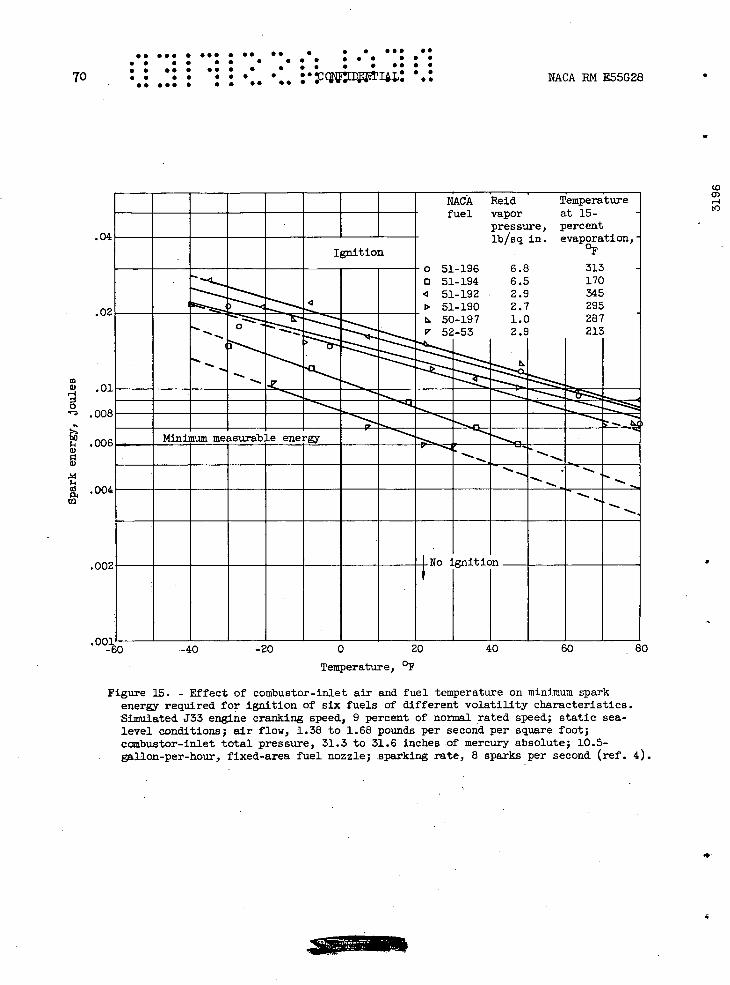
.. •.. . ... . .. .. S S I •SS •• • I I • • • S S S S S • I • • • • I SI S SI I S S S • I • •• • I
70 . . . . • • • • LJDt]3: .: NACA RN E55G28 S. •IS • I S 55 55 S
a.0]
OOE
roo€
4.00 CO
.00i. - -60
KIM
02
NACA Reid Temperature fuel vapor at 15-
pressure, percent lb/sq in. evaporation,
OF Ignition
0 51-196 6.8 313 0 51-194 6.5 170
51-192 2.9 345 > 51-190 2.7 295
50-197 1.0 287 ... - 52-53 2.9 213
-...--. --.--.-------
--- ---
Minimum measurable energy--- ---- ----
-'S
5---
5-5-
5-
No ignition______ S
Co O)
to
-40 -20 0 20 40 60 80
Temperature, OF
Figure 15. - Effect of combustor-inlet air and fuel temperature on minimum spark energy required for ignition of six fuels of different volatility characteristics. Simulated J33 engine cranking speed, 9 percent of normal rated speed; static sea-level conditions; air flow, 1.38 to 1.68 pounds per second per square foot; combustor-inlet total pressure, 31.3 to 31.6 inches of mercury absolute; 10.5- gallon-per-hour, fixed-area fuel nozzle; sparking rate, 8 sparks per second (ref. 4).

NA
CA
RN
E55G
28
.. ... . .
... .. . ... . ... ..
• . S
I • •
I S •
SS
•• •
• S
• S ••
S•
S •
•
• •
•• . .. S
•
•.
. . •
. •
S •
S S
•S IS
S •
• •
•• I.
71
O-:
.cj
•'d
D
a)a)O
O)44)
W 'd
4-) •H
-,,-1
0
ppH
0)
U)
•,-P
---J a) o
OP
P
4 r-A
r-I..
a)a
)0,-I
CC
') 0
O
0) ai
C).....
II
I ' I
0•
•__
__
I __
__
__
C
__
a) •
..
..
. C
il CH
..4-)
.O
..
:J:::.___
.0)•
. ID
' 4-
.0
•
a-,4
! W
0
HO
O
a)P
IN0
al
P4 P
4 P4
Hc
LILI
LI
LI o
0
0
0
0
0
0
0
o
0
0
0
C')
H
J 'apflfl[y
04 H
CD 0)
LI
0
(0
0
mm
0
0 a)
4.)
a)
oa)
4)
'-4 P 4-) a)
0
0
rd
4) r4 4.) H
0
U) a)
a)
a) 4-)
H
a)
CH -
rd L
fl
Cd
4-U) ,-i
0)
H p0
C4-)
4-'
Q) c
a C
H4)
C4-4 'H
. (D
Q
4-) a) H
'-I
0
- CO
o
0

L) OU du 100 120 Minuinum starting fuel flow, lb/hr
32 X103
12
420
-1 /
No ignition
/Ignition 11/ f Engine speed,
rpm
to 0) i-I
2
24
2C c-I
a)
4.)
4-)
1E
.. ... . •.. . S. •• • S S ••. S.
• S • • • • . S • • S S S S • •
T 2S
• • • • . • . . ..ONPbIflEIIAL5 . S NACA RM E55G28 •5•SS • • • •• • SSS••. •S •S• ••
Figure 17. - Effect of altitude on minimum starting fuel flow in single J33 combustor at three engine speeds. Flight Mach number, 0.6; NACA fuel 49-162; fixed-area fuel nozzle; spark energy, constant (data from ref. 1).

.. ... . . . .. .. . ... . ... .. • . • • S • • • S • • S • • • S • . •. • . . • S • • •. S •• • • • . . . . ... S • S • S S •I NACA RN E55G28 •. C DEWLj. . • •. .• . . • •,. •. 73
10
8
C
4
.2
.1
.08
• 06
.04
:i CD v
- .6
.4
20
2
Air how,. lb/(sec)(sqft)
V2.80 3.745.00
p6.40
-
Ignition p
.3\\ \__
No ignition
02
ni 4 8 12 16 20 24
Combustor-inlet total pressure, in. Hg abs
Figure 18. - Effect of air-flow rate and pressure on spark energy required for ignition in single tubular 333 combus -tor. Inlet-air temperature, -10P F; inlet-fuel temperature, _400 F; grade JP-3 fuel (NACA fuel 50-174); variable-area fuel nozzle; sparking rate, 8 sparks per second (ref. 2).

.. ... .
• •
• •
• • •• S
74
•
SS
SS
•SS
SIA
CA
RN
E55G28
LI
-'SI
a) ,-1
a)
U)
p4
..s C H
g, o 'IJH
U
)
+H
0 •'- a
) SI
r C
H
SIH
-1
SI ai
rdo
(OH
I .,-1 SI o .,-I a)
4.) rl.n
SI
4-l' —
bD
•r1N
o o
cli It)
a)a) C
') 1H
1
rd
i
SI+
'a)
0) 0
O
H
SI O
HO
SIia
)
O 0
C
U.)
U) it)
1Ia)
O 0
a) .
w
Ea
0) -, ••'c
Z.)
H a3
a)O
a
i.t' a
tto +
3 I
-i r1
0 N
0 0
4.)
.-C) '3) Co
•O
0 0 -1
j) 0
'-I
LO
LO
ca P
.
AA N
0
--
(_)ci)
W
CI)
C") CO
H
H
sqa
D H u
1 'z
nssid
io
uç-.zo4snqwo3
.0

a
.(
.(
C) ci
0 r
0 0
EQ a) H 0
a.)
ci P1
Cl)
. ... . . . •. •. . • a S •S • . . . S S S • •.p .,
• S S •I • S : 0 :C 66 S • S S • • S •• • •• S S 4 NACA RN E55G28 :Ict1cizJ. . . S. II S1 S
• S S •Sl •• 75
ir' I.
S Sa
6Air flow,
lb/(sec)(sq ft)
0 6.4 0 5.0 A 3.74
V 2.80 -
1.87 .74 .---.37
20
Ignition
4.
2
No ignition
6/_________
2/
rw
•0•1: 8 12 16 20 24 28
(ft/sec)/in. Hg abs
Figure 20. - Minimum spark energy required for ignition as function of combustor-inlet pressure and velocity. Combustor-inlet air temperature, -iO° F; combustor-inlet fuel temperature, -40 0 F; grade JP-3 fuel (NACA fuel 50-174); variable-area fuel nozzle; sparking rate, 8 sparks per second (ref. 4).
S

1600
1200
800
400
0
2000
1600
1200
800
F 0
400 a
00
28C)
2400
----Enginerri
MENEM MMMENMMMNPKWMMMMMM •ilU••i!EEUIlUU
MMMMMUMJMMMMMMMMMMI MMMMMMMMMMMMMMMMMMI
(a) Altitude, 50,000 feet.
(b) Altitude, 45,000 feet.
•• •.. • is. . S. •S • • • .5. • S .0:
• S I S S S • • • • . S
76 • • •. • •• • • ••• NACARME55G28 • S • • •
• •• •
• S •• ,. . . ... •. •.• ••
,, •,•
2000 - - - - -
1600 - - - - - -
1200of consistent Region
ignitionRegion
it1on I
0 400 800 1200 1600 2000 2400 2800 3200 3600 Wlndmilllng engine P?ed, rpm
0 .1 .2 .3 .4 .5 .6 .7 .8 .9 1.0 Flight Mach number, N0
(c) Altitude, 40,000 feet.
Figure 21. - Effect of fuel flow on altitude Ignition characteristics with MIL-F-5624A, grade JP- A fuel. Fuel temperature, approximately 500 F; engine-inlet air temperature, approximately 00 F (ref. ).
4
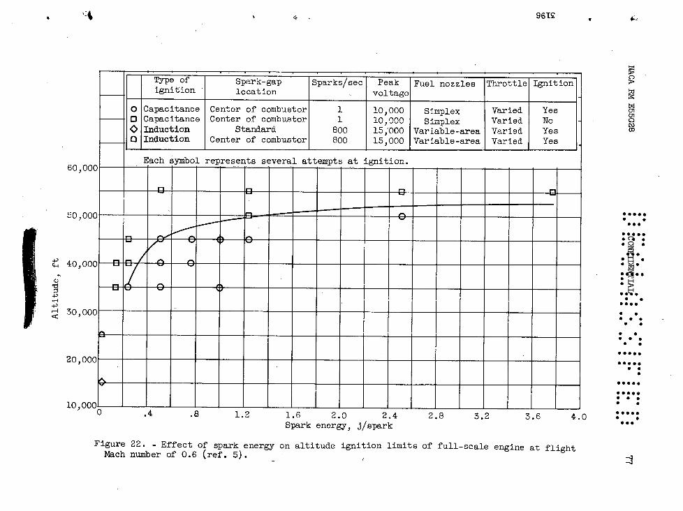
...
.. . ... S ,•
5 .5
• •
SS
5•
• •
• . .1
? •
•.
S S
e• •
•
• S
..S
5 •
•
• S
S S
• . S
.5. • •
. ... •.
NA
CA
RN
E55G
28
I Iwo
(a I-. (0 0)
0- -
4.) '-I 4.) a)
-
ci) 4.) 4.) ai 41) ci)
U)
pq
113
13
00
00
00
00
00
00
c0
00
00
0 '-4 +
a m
,-1a)0
a)a
)
H Q) -1rd
'd'd
-p
a)a
)oa)
-p o a)a)a)
a) H
Cd cc
baI
a)a
)a)a
) o
HH
HH
p4p4,a
Pa5
H44.H
.,-4
(DQ
) U)
1x4(D t4
OC
)00
a0000
cd-pO
C)0
0
a)H
- -' -
-P .i
00011)11) H
HH
H
0 a) a)
00
CD
HH
OO
0)0)
cc P1 0)
-4 00
0 p4)
4.) W
a)a)
P10
000
1r-4
000
aiO
000
P40 C
I)Hco
0a)
41)
0)(D
a) 00
0
ç C
H
0.H
0Q
P
4-4
.d-
Ø-1
r-4-44.)4.) P
4 0
0000
P4P
4rd.d 00 H
H
000a
0
bio "-I H cl-I
(0Cd
N)a) 1)
U)
ci) •
H tO
0 C')
CDH
C')ç0 a)
El
-p
j4•H
.,t4
-4
P4
4-) •r4
- bD
0') •H
C
\]-4a)
(Drd
kd 1)
.4)
H (O
cd r-C
J)0 bOLo
OD
U) a).
H
P44-I
Wa)
cl_I 0
(0
4-).
00
(1) cH
q_
I
'U)
.,
C'J
D
ILl
6
6
6
6
6
6
(0
U)
NO
N)
Cl)
H
'GP
n4T
4T
V
S
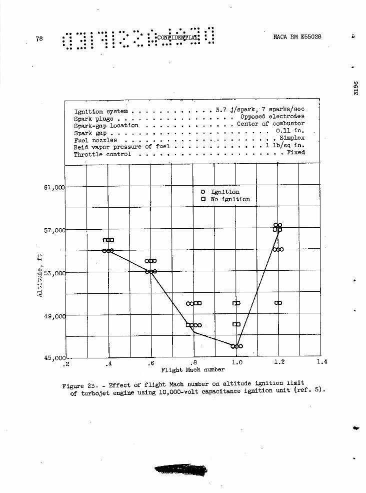
••. S.. S ••. S •• •• . . • 5. ••
• • • . . .
• • •• • •• • . .
:0. -CON I! : : NPCA RN E55G28 78 S • S •S I
• • . S • S S ••.
S. 555 • • • .• .. S S ••. •. ••. 50
(0
-4 to
6l,oa
57,001
-I-)
'53,0O
H
49,00
45,00G - .2
Ignition system ............3.7 i/spark, 7 sparks/sec Spark plugs .................Opposed electrodes
Spark-gap location .............Center of combustor
Spark gap .......................0.11 in.
Fuel nozzles .......................Simplex Reid vapor pressure of fuel ..............1 lb/sq in. Throttle control .....................Fixed
o Ignition O No ignition
Li
--_
OCIDDED C)
.4 .6 .8 1.0 1.2 1.4 Flight Mach number
Figure 23. - Effect of flight Mach number on altitude ignition limit
of turbojet engine using 10,000-volt capacitance ignition unit (ref. 5).

4N
AC
A R
14 E
55G
28
•.S
..•
• •
S. • . .
. . S
• • • • . •S
EeA
L' •
• • •
•0
• ••
••••• IS
') • • ••
a, •
••• •
••• ..
•. S
• •• •
•. S
.• ••
• •
. S S
••
• •
S. 5
S
• •
•• •
•79
0 Cd
+) .-I 04-4 00
U, 0 P4
-40
00 U,
00
N--
N N
-00
4-i
0-
4-4 .-4
0 k '-4
I'4 0 U,
ON
00
11i
A-..• .'c-.'...-: •.-• 4.11i
eY
.4
I to
r-1 a,
(0 Fl a)
(0 t4) to 0I CD Ck a, 0
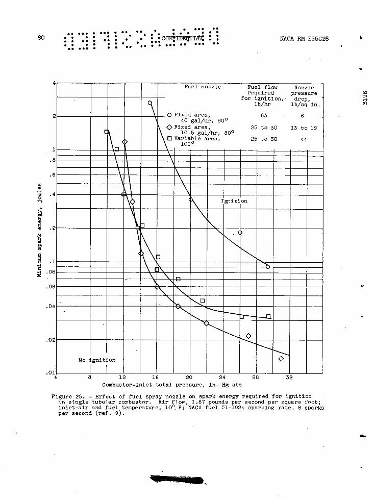
S.. S •S • •S• • S • S • S. • • • • S • • • • •50 • S as •• • •
• S •S •S • S S
. • S. ONZ : NPLCA RN E55G28 Ij.. •. ... S. t
.. 80 S. • •
• S S.
M.
m
bo
0.
'-I
OE
.OE
4Fuel nozzle Fuel flow Nozzle
required pressure for ignition, drop
lb/hr lb/sq in.
o Fixed area, 63 6 40 gal/hr, 80
v
Fixed area, 25 to 30 13 to 19 10.5 gal/hr. 800
Variable area, 25to3Q44
__EEEEEEEEEEE Igniti on
N _-
-------__
No ignition
(0 0)
a.
.014 8 12 16 20 24 28 32
Combustor-Inlet total pressure, in. Hg abs
Figure 25. - Effect of fuel spray nozzle on spark energy required for ignition in single tubular combustor. Air flow, 1.87 pounds per second per square foot; inlet-air and fuel temperature, 10°. F; NACA fuel 51-192; sparking rate, 8 sparks per second (ref. 9).

S. ••• • • • . S. •• • •,. • S.. •• • S NtCARME55G28 • .CIFIjNTj.L S • • • •
S .. . S. S S 81 000 09 000 •,• , • • * • • •
I-'
O)
.04
'-4
(I) r
(L)
C) .00E
C)
0
.00E
S
.004 Cd
PA U)
.001 - 150
00
02
I I
NACA Reid. vapor fuel pressure, -
lb/sq in. -
-o 51-196 6.8 - 0 51-194 6.5 4 51-192 2.9 - D 51-190 2.7 L 50-197 1.0 - V 52-53 2.9
Combustor-inlet air and fuel temperature,
OF
-40
Ignition
I
V I
—80
No ignition
200 250 300 350
A.S.T.M. 15-percent evaporated fuel temperature, OF
Figure 26. - Minimum spark energy required in single J33 combustor for ignition of six fuels as function of 15-percent evaporated fuel temperature at several combustor-inlet air and fuel temperatures. Simulated engine cranking speed, 9 percent of normal rated speed; static sea-level con-ditions; 10.5-gallon-per-hour, fixed-area fuel nozzle; sparking rate, 8 sparks. per second (ref. 4).
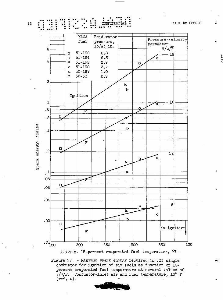
NACA Reid vapor fuel pressure,
lb/sq in.
o 51-196 6.8 o 51-194 6.5
• 1 51-192 2.9 D 51-190 2.7
50-197 1.0 v 52-53 2.9
pressure-velocity parameter,
Ignition 7<D.
D
12
0 6
— V No init1oJ
6
4
1
.8
.6
U) ci) H
ci)
p4 Co
.1
0€
04
0
.. ... .SSS••• •I • • • ... S.
82. SS
• • •• • •, . . • • • • • : NACA E55G28
• • • • • • a •
• • • • •• SO S S••' . S.
200 250 300 350
400
A.S.T.M. 15-percent evaporated fuel temperature, OF
Figure 27. - Minimum spark energy required in J33 single combustor for ignition of six fuels as function of 15-percent evaporated fuel temperature at several values of V/'/. Combustor-inlet air and fuel temperature, 100 F (ref. 4).
IN

NACA RIVI E55G28
•. ... . . . S. •• • •• • •.. I. : S
• . • . . . . . . . • S •
• • • ..• . I • •• • I• S • 83 • • • . S I S • •
.• S.. •• ••• • • I. S. •. • • ••• ••
1600
120C
0 H c-i H 80C W
0 0
40C
-Fuel Reid vapor
pressure,_ lb/sq in.
Grade JP-3 5.4 - - Grade JP-4 2.8
-—
Ignition
No ignition
-:
0 400 800 1200 1600 2000 2400 2800 Windmilling engine speed, rpm
I I I I I I I I I
0 .1 .2 .3 .4 .5 .6 .7 .8 CdFlight Mach number
'-4 H Figure 28. - Effect of two grades of fuel on altitude ignition
characteristics. Fuel temperature, approximately 50 0 F; engine-0
Inlet air temperature, approximately 0 0 F; altitude, 45,000 feet (data from ref. 6).
40,000
30,000
a,
Is20,000
4) -f 4) '-I -Reid vapor
pressure, lb/sq in.
10,0005.4(AI-F-58) 1.1
0 .2 .4 .6 .9 1.0 Flight Mach number
(a) Engine with axial-flow compressor and duplex fuel nozzles (ref. 10).
Figure 29. - Effect of fuel volatility on altitude ignition limits of turbojet engine.
ThL

50,00C
40, OOC
4) 30,00C
20,00(
10,00(
Ignition system ....... . 0.02 i/spark, 800 sparks/sec Spark plugs .................... A.C. F-67 Soark electrode location ..............Standard Spark gap ......................0.11 in. Fuel nozzle ... ............... Variable-area Fuel .........................Varied Throttle control ...................Varied
Reid vapor pressure of fuel, lb/sq in.
\\\
('I F.
O)
S .• •SS • 55 • . 0 0
0 ••S S S•S
84 a S • • • ,• • • • • • ccFIIwTlT1L: : NACA RN E55G28 , • S I S • S S 0.0 • •S.
I S S •. • S.. •S •.. S. •SS
••
0 .2 .4 .6 ,8 1.0 Flight Mach number
(b) Engine with axial-flow compressor and variable-area fuel nozzles (ref. 5).
Figure 29. - Continued. Effect of fuel volatility on altitude ignition limits of turbojet engine.
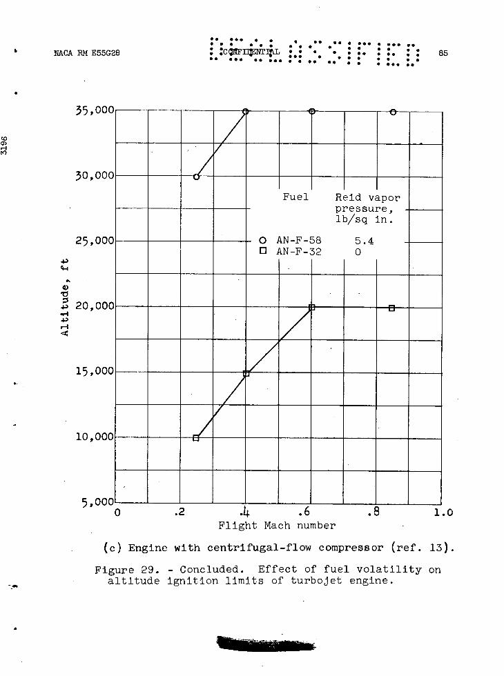
•• ••• • .85
• .C3FnaTIgL • • . . . .• • •• NACARME55G28 .•. I I I • • • • .
35,000
30,000
I
Fuel Reid vapor pressure, lb/sq in.
o AN-F-58 5.4 o AN-F-32 0
25,0 IN z
43
4-4
41)
43 20,0
15,000
10,000
5,0 DOL 0 . 4 .b • d 1.0
Flight Mach number
(c) Engine with centrifugal-flow compressor (ref. 13).
Figure 29. - Concluded. Effect of fuel volatility on altitude ignition limits of turbojet engine.

4) (O
H
g: r00 -c
+
)r-1
U_
4I
Ia)
,D iH
0
C
C)r-4
Ea)a
-1)
OD
(D
•r4 4.) (() H
H.
If) C
-
00 a
+)r-1
ci) rfJa) a5
a-i 0
-1
-i
1 00
0ca
•-1 to Z 4
-' +
't')a3
4.)1
xi'-
a)a) P
4H
O )
U) L
ID
g
-cH
C')
ia
Pi-
1 i
0
C,)-
H0C
0-4
-i
4)-4 P
ici)
U) b
O U
) U)
c H
-i
0a)'
rd
o
C') aiH
U
)&)
N D
--i 0
bO
.'-1
pq
0.
0 0 0 H 0 0 .-0
0
a) cr
Ea
ai Pi U)
U) 4.) Cd
0
4.) -'-4 4) ci) a
)-
DC
!)
rl
CO 0)
di
S. •S
• • •S• • ••
••S
• S ••
• ••. • •5
• S
• • S
••
• •
. S
• S
86
• • •. • •
''
co!F
ID S
rIAL
I S
I 5N
AC
A R
M E
55G28
• .
S •
• •
•
a•SS
S.
•IS
•
• •
••S
. S • •S
• ••••.
••
_01
-
0.—
NO
Ir)-
r4'
aiH
C'JV
)
-
oD
.
0-1 4) •r-4
1 I / /
1 I I I
0 4.) -'-4
0
C)
(0
C\] aD
(\JH
H
sq
a o
ll UT
'rnssid
I01
TuT
-1onqtuoo
OPT
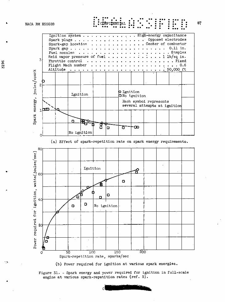
Ignition system ............. . High-energy capacitance Spa'k plugs .................Opposed electrodes Spark-gap location. . . . . . . . . . . . . . Center of combustor Spark gap ........................0.11 in. Fuel nozzles ......................Simplex Reid vapor pressure of fuel ......... . . . 1 lb/sq in. Throttle control ......................Fixed Flight Mach number .....................0.6 Altitude .......................- 50,000 ft
0 Ignition Ignition ONo Ignition
N. Each symbol represents several attempts at ignitioi
0
0 0 D0 No ignition
(0 3
0) H
(1)
Co ()2
H
0
a)
ci)
Co
C
•. ØSS S S • •• •• S •S• • .55 50 • . . . . 87 : : • . . •. . NACARME55G28 CI T AL • 000 4 * 0605I• • . 5 • S S • 5 •00
(a) Effect of spark-repetition rate on spark energy requirements.
80
Ignition
60
40_____
011111 / o 0 No ignition
2(( 1111 0 50 100 150 200
Spark-repetition rate, :5P3k5/5ec
(b) Power required for ignition at various spark energies.
Figure 31. - Spark energy and power required for ignition in full-scale engine at various spark-repetition rates (ref. 5).
C
C.) a) to
to a) -1
0
to 4.) 4.)
0
0 c-i rd ci)
I

S. ••. S ••• • •• •• S • • ••. .. •
88 • • • • S • S • • • S FI
S S S S
• • ,• • .• . • • ' CE!]I; : NACA RN E55G28 • S S • S S • • •• S. 55.5 5 5 •• S. • • ••• • •5. 55
Trigger Spark-repetition condenser rate control gap
Pulse transformer
Storage Ignitor d-c supply -r- condenser t gap
(a) Triggered low-loss system; for air-gap ignitors only.
4
S
d-c supply
Trigger condenser-
Storage
condenser
Pulse
Barrier gaptransformer
Igni gap
- -Carbon _ fouling
(b) Triggered system with barrier gap; for air-gap or surface-discharge ignitors.
Barrier gap
d-c supply Storage < Ignitor gap—condenser
3 Semi-conductive surface
(c) Nontriggered system; for surface-discharge ignitors only.
Figure 32. - Basic circuits of low-voltage high-energy spark ig-nition systems.
S

S. ••• • • S •S •• 5 S.. • ••• •• • . S S S • • • • . . . . . S • • c FIINTI2.L . . . . •• • • 89 • . NACABME55G28 •.. S S • • • • . . so * 00 0*0
6
4
CD
H to
1
.8
.6
Cl) 11)
H
('3 r
0 0
bO
c) .
lid
Cli
aD
E.1
.08
- .06
.04
.02
-Air flow,
-lb/(sec)(sq ft)--
--
- --
3.75 Ignition system
-g Triggered (fg.l)
1.87
Burning limits
3.75
Ignition
ii
No ignit ion—IIE;IiiIii8 12 16 20 24 28 32
Combustor-inlet total pressure, in. Hg abs
Figure 33. - Comparison of combustor Ignition energy requirements in single tubular J33 combustor with two ignition systems. Air-gap ignitor; inlet-air and fuel temperature, 10 0 F; NACA fuel 50-197; 10.5-gallon-per-hour, fixed-area fuel nozzle (ref. 9).
.014

Ignitor
- o Wire electrode - (ref. ignitor)
0 Disk electrode -
Ignition
No ignition
5
4
-4
0
F 1
In
.. ... . ... . S. •S • • • S.. SI
90 •. .. .. . •.•C?I:: • S S. • SI S S • • • I S S • • . I • S S S I •S. S S. ••I I S S •S IS S S 555 SI SSI SI
NACA RN E55G284
Adjust10 nut
ON Ir
T77 CP
I Wire electrode
/
'aM
14electrode
/
(0 C) H
I CD-3274
04 .08 .12 .16 .20 .24 Electrode spacing, in.
(a) Effect of electrode spacing. Air flow, 1.87 pounds per square foot; inlet-air pressure, 12 inches of mercury absolute; 10.5-gallon-per-hour, fixed-area fuel nozzle.
Figure 34. - Ignition energy requirements of single tubular J33 combustor. Low-loss ignition system; inlet-air and fuel temperature, ld F; NACA fuel 50-197; sparking rate, 8 sparks per second (ref. 9).
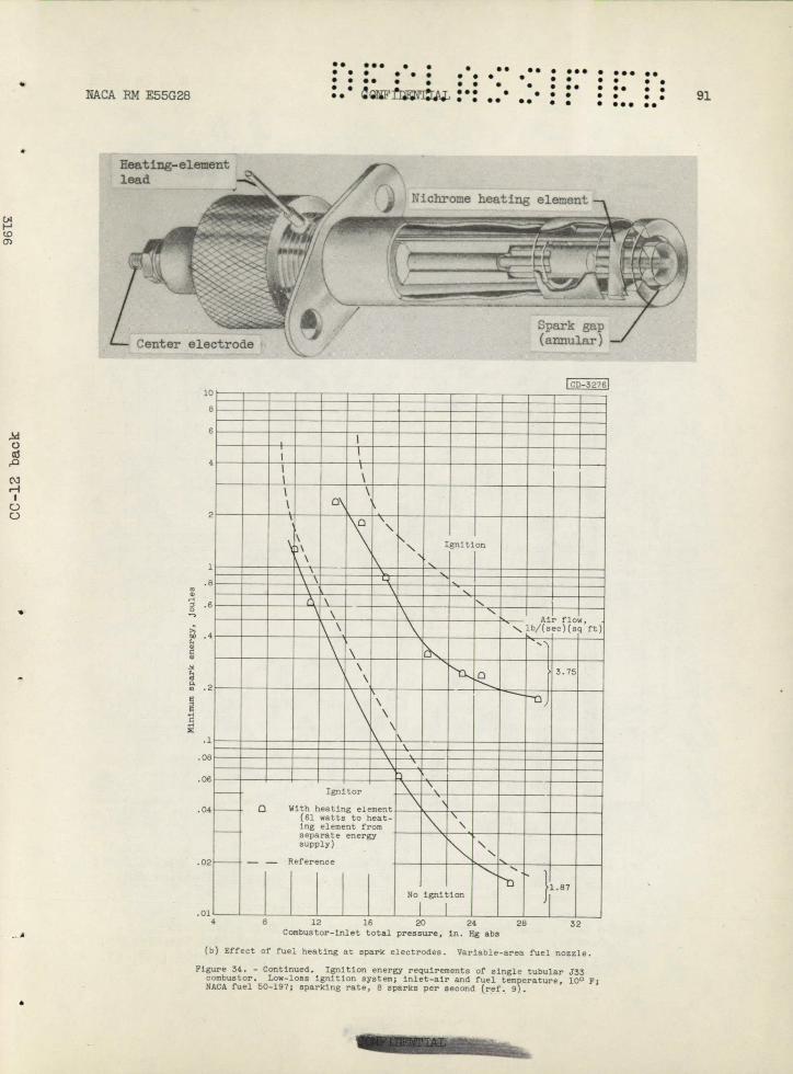
C,
0 •
C. C, C
-
E
C
• 0
.06
• 06
•. ... . ..
S • S • • • • . • • .. S S S S • . NACA P14 E55G28 05 IFIñ ••' S •
S. •• • ••• • S.. 55 • S • • • • . S • . . .. S •• • • S S • • • • S • .. S. • • • ••• S.
Heating-element lead I"
Nichronie heating element .s ---•• ----,.----
Spark gap Center electrode (annular)
CD-3 276)
0
C\1 r0 o
ii
- -----
\0
\ \
,Ignition
-
Airflow, '.,lb/(sec)(sq ft)
4 \ -
^D
Ignitor
0 With heating element (61 watts to heat- Ing element from separate energy supply)
- - Reference
-
\ "
-
-\_
- \
'-S
-
S-
- -
- -
No ignition
'D
-
1.87
01
.01 4 8 12 16 20 24 28 32
Combustor-inlet total pressure, in. Hg abs
(b) Effect of fuel heating at spark electrodes. Variable-area fuel nozzle.
F1re 34. - Continued. Ignition energy requirements of single tubular J33 :bustor. Low-loss ignition system; inlet-air and fuel temperature, 100 ;
NACA fuel 50-197; sparking rate, 8 sparks per second (ref. 9).

S. ••• S •SS S S• •• • S S ••. •. • S S S • S S • S • I S S S • •
• I 92 • • •. . .. • • ' ' CFITI
IL. • NACA EM E55G28
• S • I • S • S SI. •5 SIS S S S 55 •• • • S.. •S •SS •S
Standard installation; Cooling air reduced; No cooling air; no diametral diametral clearance clearance or cooling-air hole.
-inch diametral clearance reduced to zero. between ignitor and combustor; cooling-air hole open.
CD- 3468
LOi I I I I I I I I I
8
6
4
2
1
.8 a
.6 0
.4 bo
cd
a C a
. .2
0. M E
.1 C .08 '-4
.06
.04
02
.01 .008
.006-8 12 16 20 24 28 32
Combustor-inlet total pressure s in. Hg abs
(c) Effect of air flow at spark gap. 10.5-Gallon-per-hour, fixed-area fuel nozzle.
Figure 34. - Concluded. Ignition energy requirements of single tubular J33 combustor. Low-loss ignition system; inlet-air and fuel ternperatore, 100 F; NACA fuel 50-197; sparking rate, & sparks per second (ref. s).
ILILI
-----------------
Ail ---'It---------
- It;JiIIiVIIIUIIflI /4IWUI
•uuiiiuuiiuuu•uu•• IiIIliMihlIUlIIIli MAMMOMMOMMIM
36
to 0) H

8 12 16 20
Combustor-inlet total pressure, in. Hg abs
(A I.-. c.o 0) E
14
I 1
Triggered ignitor Nontriggered ignitor -
- - - - Reference ignitor
lb/(sec)(sq Air flow,
ft)
ii1.87 3.75
_
I
I 1I
_1.87
Burning limits
_3.75
I I
I I
No ignition
I I
I I
a
0
a)
CU p4
Triggered
ignitor
Non-
triggered
ignitor
LCD- 3127 I
S. ••
•••• • • • .. . S. .5 • ••• • ... .. • S S . . . . . S • • . S. S • • • • S S •• • •• • S 93 NACA RN E55G28 :.'ci'rj. •.. • . . • . . •
. S • •S •S • • • ••• S.
Figure 35. - Comparison of ignition limits of single tubular J33 combustor with nontriggered and triggered surface-discharge ignitors and with reference air-gap ignitor. Triggered ignition system with barrier gap; inlet-air and fuel temperature, 100 F; NACA fuel 50-197; 10.5-gallon-per-hour, fixed-area fuel nozzle (ref. 9).
S
C
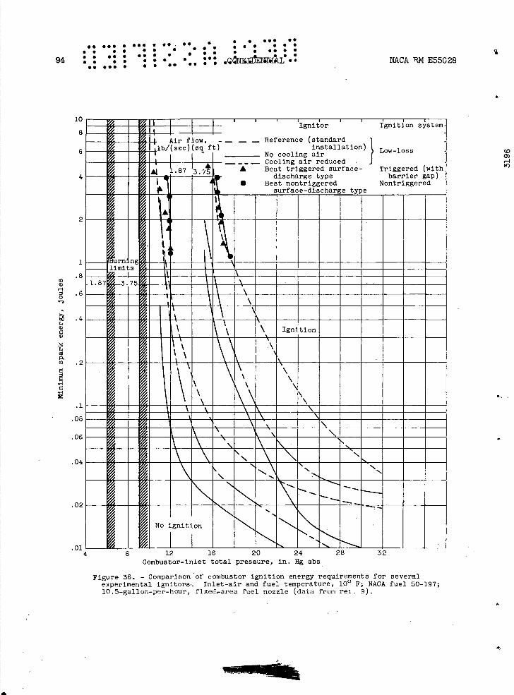
.. S.. S ••S • SI SI I I S SI. II • S • I II S III IIS II•
94 I S IIS 55• I I SS • S 5115 • I I S • • I S •II NP.CA RM E55G28 S. III S I • •• •• • S S
.02
10
8
6
4
01 - 4
2
- - -.
- !• U11!U
KAFIRI MENEM 0UU1 - - l_J___ ---------
•UIIIUUUUEU•U IiIII,IIIUIIIUIUUII j^11Mj,0AjjjjjjjjjIIIUI
•iiiumuiiuuuii
C)
8 12 16 20 24 62 Combustor-inlet total pressure, in. Hg abs
Figure 36. - Comparison of combustor ignition energy requirements for several experimental ignitors. Inlet-air and fuel temperature, 10 0 F; NACA fuel 50-197; 10.5-gallon-per-hour, fixed-area fuel nozzle (data from rel. 9).
1
.8 a) a)
.6
.4 a) 8 a)
Cd 0. a) .2 C
1 8
.1
.08
.06
.04

•. •.. . . . •• •. . .. ø S ••• •• S • • • • . S S • • •
IIN' 11L . • • S • •• • •• S NACA RN E55G28 c 'ID • • *•. S.. is is. S S Si •• • • S ••• ••
1
G) .8 ,-1
0 '- .6
bO
a) .4 a)
(5
Ei
0.
.2
€ H
O)
4
4 .1
.08
.06
.04
Igritor'plug'localion I
Centerline of combustor Midway between centerline and -
edge of nominal spray cone Outside of nominal spray cone -
- - - Standard
0 01
Burning-limit
Nominal fuel spray. path in still air
[
__-
INo ignition .
I 1 :1.028 12 16 - 20 24 28 - 32 36
Combustor-inlet total pressure, in. Hg abs
Figure 37. - Effect of spark-gap immersion depth on ignition energy requirements of single tubular J33 combustor. Low-loss ignition system; air flow, 3.75 pounds per second per square foot; inlet-air and fuel temperature, 10 0 F; NACA fuel 50-197; 10.5-gallon-per-hour, fixed-area fuel nozzle; sparking rate, 8 sparks per second (ref. 9).
0
r.

.. 96 . • •
• • •.
S.. S • . .• . • . ... .
a)
4) '-4 4) H
20,00c
10,00C
.4 .6 Te 1.0 Flight Mach number
Spark plug1
Standard position /
•
•Center of combustor
Fuel nozzle ..—Nominal fuel-spray
path
I I I
Ignition system ..........0.02 i/spark, 800 sparks/sec Spark plugs . . . . . . . . . . A.C. F-67 and opposed electrodes Spark electrode location ................Varied Spark gap ...................0.17 to 0.18 in. Fuel nozzles . . . . . . . . . . . . . . . . . . . Variable-area Reid vapor pressure of fuel .............1 lb/sq in. Throttle, control ....................Varied
Spark-gap immersion
0 Center of combustor 0 Standard position
No ignition
Ignition
9
0 .2
40,00C
4) 30,00C CH
.. . .• .. . • • S • • •
S. S S • • • • . . . •.• • . S. •• • •
• S.. •. . S •
C• NENIAI • NACA RN E55G28 • . S • S S.. •S •.. ••
Figure 38. - Effect of spark-gap immersion on altitude ignition limits of turbojet engine (ref. 5).

to r
0
0
9-1
a)1€
2 3 4 5 6 Air flow, lb/(sec)(sq ft)
24
41
I I I. I I I I I Combustor-inlet ignition source air and fuel
- temperature, 0 10-joule 1 OF 0 0.3-joule 8 sparks/sec
(ref. 2) J 10 V Aluminum borohydride
-46
0 Burning limits
/
010_J3
No burning or ignition -
CO
cu 2C
i1
S
CO
a)
P4
H
S
4-)
0 -4-) ,
l
-4-)
a) H
0
4-) S
I
.. • •. S • • • • . S .
IflNTI • ofiL .. S.. •S S 97 NACARME55G28
••• • • I. 55 • •
... S • •• • . S..
Figure 39.. - Comparison of burning limits with ignition limits obtained with electric spark and with aluminum
• borohydride as sources of ignition in J33 single combus-tor. NACA fuel 50-197; Reid vapor pressure of fuel, 1 pound per square inch; 10.5-gallon-per-hour, fixed-area fuel nozzle;-spray-cone angle, 80 0 (ref. 3).

Air flow,
6.00 fig. 39
WENN11 0
u-I umi•_
V
4 IlW%%'t!U I"w"
LU -I
WA •
ii —a
IWt\i-_
,J1 MENEEMENEENN1
_A_•_
MENNE INo II.
N I-
___
_ _
'vu 80
60
40
20
10 a
6
4
H
0
bo
a .a a
a
U)
.4
.2
.1
.06
.06
.04
.01
(0 0)
0.
98 •• . ' • • , • • • • • . . NACA RN E55G28 • • •• • • • • e • • • • • S • • • • . ... . . . . .
S. •SS SS S •S •S S S •SS •S SS• SI
0 5 10 15 20 25 30 v/.fl, (ft/sec)/in. Hg abs
Figure 40. - Minimum spark energy required for ignition as a function of conthustor-inlet air pressure and velocity. Combustor-inlet air and fuel temperature, 10 0 F; NACA fuel 50-197 (ref. 3).

S. •SS • • • •3 SS S •• • •• S •• • • S S S 3
NACA RN E55G28 • QNFDN1IAL.. S • S•
• . . .• . .• • . 99 • . 3 5 . S ••• S •S • • S • S •. ..• .. ... S • •• •3 • • S •SS •S
55,00C
F45 00C C)
a
4)
35,OOC
--s----
S. -
Cross-fire-tube - diameter,
in.
7 (Standard)
: 8 2
Flame propagation limit ---Limited by ignition only
0 Cd
to r
0 0
25,00C2.4 .6 .8 1.0
Flight Mach number
Figure 41. - Effect of cross-fire-tube diameter on flame propagation limits of turbojet engine with variable-area fuel nozzles and standard cross-fire-tube location (ref. 5).
60,00
55,00(
F
50,00( F
F H
45,00(
40,00( .2 .4 .6 .8 1.0
Flight Mach number
Figure 42. - Effect of cross-fire-tube location on flame propagation limits of turbojet engine with 2-inch-diameter cross-fire tubes and variable-area fuel nozzles (ref. 5).
iL
Cross-fire-tube loca-tion, In. downstream of fuel-nozzle tip
o 5 (Standard) o 7.5
10
Flame propagation limit — --LimitedbyIgnitiononly
I,
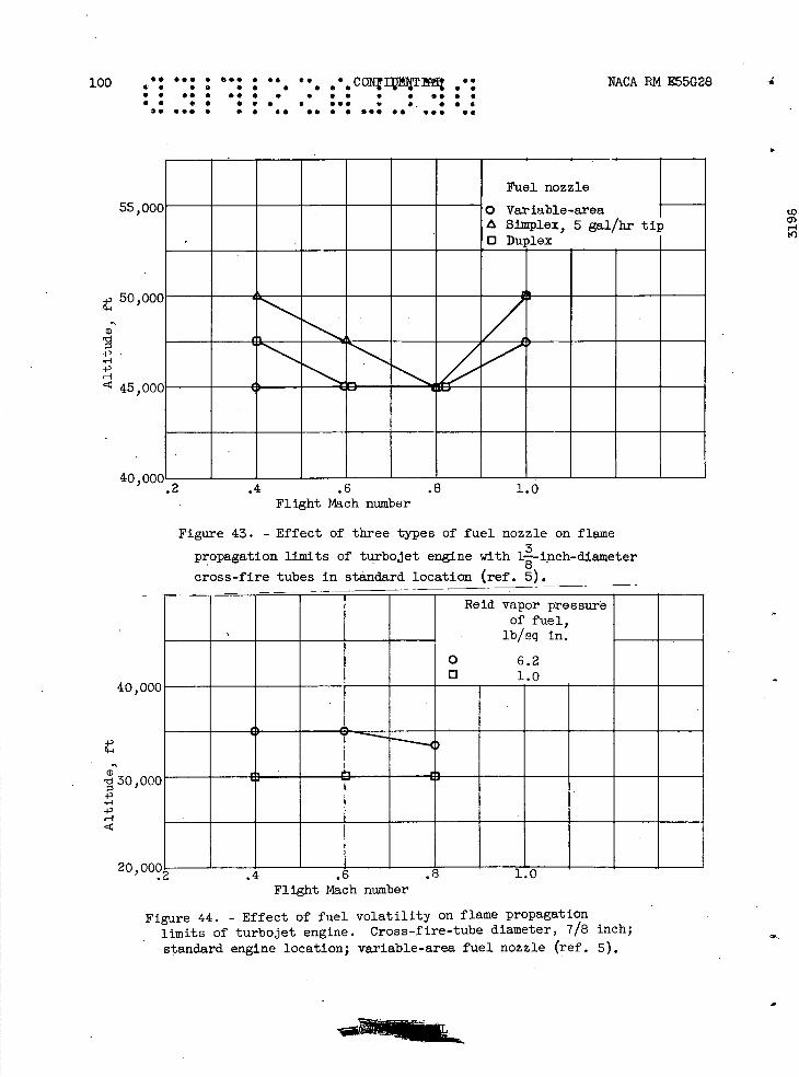
40,
20,
4,
30, 4, '-4 4-, H
100 • a
a • a . a a a a a C0tTf .: NACA RN E55G28
• a •a a .. a . a • • • • a. a a
• . 1 • • a a •.I • . S •
00 •.• • S. •• •. a S ••• •• •.• •
55,
50,
a
-I-' - '-3 4D H
45,
40,
Fuel nozzle
000 0 Variable-area A Simplex, 5 gal/hr tip 0. Duplex
ooc
OOG 3
000,.2 .4 .6 .8 1.0
Flight Mach number
Figure 43. - Effect of three types of fuel nozzle on flame
propagation limits of turbojet engine with It-inch-diameter
cross-fire tubes in standard location (ref. 5).
to O) '-I 1')
Flight Mach number
Figure 44. - Effect of fuel volatility on flame propagation - limits of turbojet engine. Cross-fire-tube diameter, 7/8 inch;
standard engine location; variable-area fuel nozzle (ref. 5).

NACA RN E55G28 'S F1)NIAL '. .' ' S. ' ' 10]. . . . S S S • • S • . • . .• I I • I • • S •• I •S I
S I
• . S S • ••• S • S I I • S S. S•S •• ••S I S •S 55 S • S ••I •S
0I I—. (0 0)
1.5 - 4000
-
-
Path - burst
of
encountered
typical run with
(run
throttle-no surge-
1) 7
- - -Path of tathrottle-
burst run with surge encountered (run 2)
-
// ( Recovery line - - -
- - - - - Sun g ^
I Steady-state operating line at 35,000 ft (flight Mach number, 0.20; exhaust-nozzle area 614 sq in.)
7 /
Surge encountered- 77 ____
- - — Recov ry from surge
--
4400 4600 5200 5600 6000 6400 6800 7200 7600 8000 Corrected engine speed, rpm
Figure 45. - Relation of compressor steady-state operating line to surge and recovery limits (ref. 6).
6.0
5.5
5.0
4.5 0
4.0 to
g a W
(1 3.0
2.5
2.0

S. •S• • ••S • • e .. • . . S.. •• • . • S • • • . • . 102 . . e' . .. . . . . COAAdTIA1 • S •I 0• . •ø• S • S S S -
'SS ••S S SI S• •S S I •SS •• •S• ••
501
NACA RN E55G28
40
(0 Oj
Altitude, ft
45,000 -
30 C-) ci) U)
35,000 20
1025,000 -
15,000
Iii 70 75 80 85 90 95 100
Engine speed, percent of rated
Figure 46. - Typical altitude acceleration in J47 engine. Grade JP-1 fuel.
Flight Mach number
0.37 20
C) ci) U)
U) .57 -
10 .62
0 1 1- I I
70 75 80 85 90 95 100 Engine speed, percent of rated
Figure 47. - Effect of flight Mach numbez on acceleration in J47 engine. Altitude, 40,000 feet; grade JP-1 fuel.
__

NACA PM E55G28 CONFIDENTIAL 103
CA
CD 0)
100
80
60
40
C, 4, co
C 20
0
4' c C) C, U
0
C) C)
a
100
bo
nozzle
z le
HHHH 12 14 16 1
(a) Altitude, 15,000 feet.
-area
Cons 80
60
40
20
(b) Altitude, 45,000 feet.
Figure 48. - Comparison of acceleration times with variable-area nozzle and constant-area nozzle for thrust-selector bursts from 10 to 90 degrees. Flight Mach number, 0.19 (ref. 24).

S 0 0 co N
a)(0
0)
0 0 N
0 0 0 N
OP
i 0
(0
a) a)
(I)
a)
o
r
cm 9
1
(0 V
'I
0
0
Co
If)
a) O
s-i
[IF 0
O
OH
r1
4-4
r1
ft
0 C
P4 a)0
(a
.Lf)
i() a)
•,-10)
id
1+' H
0
0
If)
104 • •
. • •
•• •
•.•
•.•
• •
• C
Or'IL
NT
iA1
•••
• •
!• • S
• •
•• S
55S
SI • I
II IS
S • S
0S
I S
IIII
•S
S I I
50555
S I S
I0II5
ISS
SI IS
I II
a '0
—
-ilPi
'P
do
0
.-
.-
0)0
) —
H
')O
V)-
H4
00<
<0
o 0
0
0 o
0
0
0 If)
)
OS
/TX
iciJ '€4J
WflIU
TX
}
NA
CA
RN
E55G
28
0
0 0
If) 0
0
–I
cl—
I --'
0 00)
Q)4)
HJ
cl-i 1xj cl-i
od
,JIa) a)
9-1
1-ti

:1.
•.•
S. S
••• •
555
S S
•S
S S
• •
• •
• S
••
SS
•S
SS
• 5
5 5•• • •
• .
SS
I1
15
5S
S S
•
SS
• 5•
••• u
I• S
S• S
• •
•
••
S •
S 5
51 •S
NA
CA
RN
E55G
28
C a)
boO
4.0 C H
))Cia) C
)) -
LO O
H
0))
N
mH
a).-)CC) 0a)
0 -
H
.0,-)
PO
4.)a)
H)) a)).)
a))) 0
HC
-E
E
I. C)E
0.-)
a)' H
a)4
.'a)
-
4
-) i-u
))
C) C
)-.-
C.).0
i-u ID bc
----
4-uC
,-) -
'
bo
--
---
(U
G---
-------i----------------h----
,-)))C)
\
cd
C:l
CU
Nt
wo
Cd
• p
0 oa o. oa U
) 0) 0
) 0) 0
) 0)
pq
-
4 -
-
-•---_
-
-. 0000000000
-
W '1
000 0
000000
ii.04-.
000 0
000000
114-uoufluo
)OLO
LO
LO
U)O
LO
\ •U
4-H
,-I H
CU
C)) CU U
) 'U) U)-
-.-
--
p'.4
-'
H10
0
-
--
133F
r\
oU
0
av---
.4
gcja
-1
HOO
oH
O
a).U
4-' a)
C))
0 a
CD
0)
r1
Y)0 0
-j
C')
c-u a) C.
C) C. a) a, a) C. 0.
4-u C) H
C' F. 0 a,
D )
C) Ci 0. E 0 C) C a)
0
H
4-u
H a)
C' 6-.
a) C H
C)a))
.0 C
a) C
)
bo4)
)H C'
- 0
C) I
C. C' 0
a)
H
) )
.0 D
a) Ci
C. 0. 0
4) H
U
)
a) C
' 4-u
.0
O
a) i-u
0 C) 4-) a)
'0 H
C
4-) a
)
0 H
I H
C
.
a) 0
4. Ia
) a)
Ia) a
) C.
C.0
0. 0)
E
a) O
C)
0 C
. 0. E 0 C)
0
U) Ii) C.
H
14.
Li
0
0
0
0
0
0
C))H
zsu-i
0
0
0
0
0
0
0
0
0
0)
0)
N
co U
)U)
ni/qi 'M
oIJ Ianj auu

106 of .., . ... • •• ,• • CO1FI11T.Ip. NkCA P14 E55G28
4 • S S • • S • • S • S • • • • S
S. •* S S• S S I S • S • •• • • • S S S S S S a •.. S S •S.
•5øs•. • I 55 •• S I ••S 55 ••• 55
0
52x103—- - -- -- -
48--Operational
191 limit —
Cd
-----
44--
-
40-----
/ 4 / —
36---
Maximum temperature rise obtainable minus temper- ature rise required—
32 -- - --- -- -
•.
28 81 - - 500 459
2(4 6 8 10 12 14 _l
Simulated engine speed, rpm
Figure 51. - Available acceleration of 19XB-1 turbojet engine as indicated by difference between maximum temperature rise obtain-able in investigation of combustor and temperature rise required for nonaccelerating engine operation.
(0 0)
LI
L
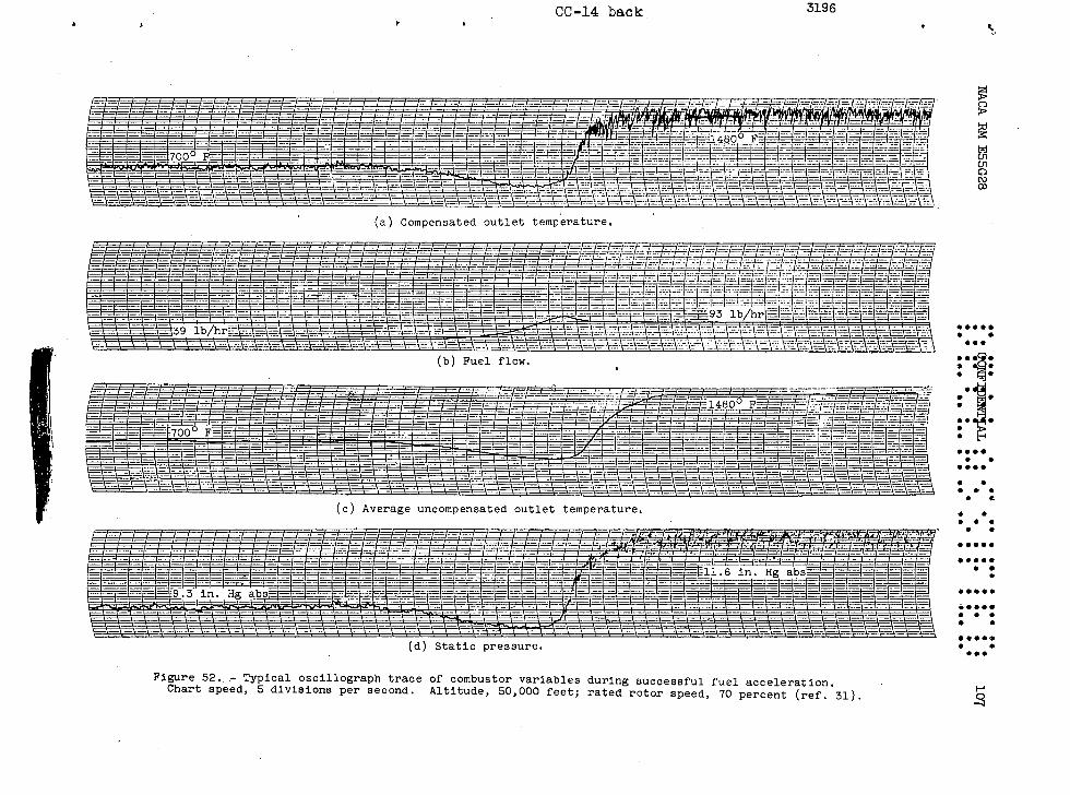
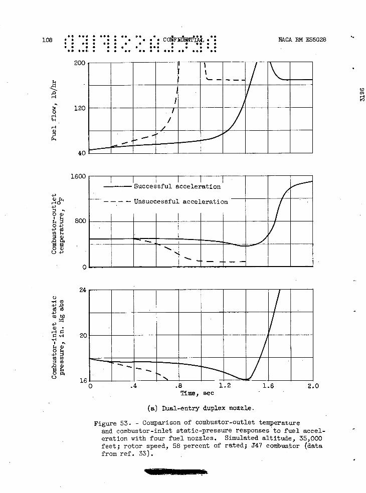
SSI • ••S I SI DI • 04F1Ir]'AL S S 108 • a • . is . S • • . •SS •• • • . S • I • •• I I • S I I I I I I •IS I S • I
S. •S• • S S •• IS • I III II IS 52
200
120
NPCA RN E55G28
(0 0) H to I
/
on MM
I I I Successful acceleration
- - - - Unsuccessful acceleration
.4 .8 1.2 1.6 2.0 Time, sec
(a) Dual-entry duplex nozzle.
Figure 53. - Comparison of combustor-outlet temperature and combustor-inlet static-pressure responses to fuel accel-eration with four fuel nozzles. Simulated altitude, 35,000 feet; rotor speed, 58 percent of rated; 347 combustor (data from ref. 33).
-i
r-1
111
40
1600
I) '-4 4-)
Oa)
800 04-)
EO
U)
0a 04-'
0
24 C)
.,-1 U)
ai •1-'
4-)
20
00 P4 0
16
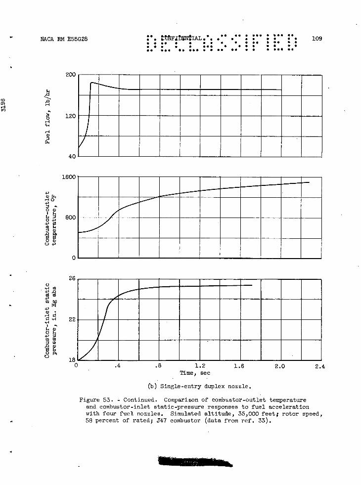
N&CA RM E55G28 V. S a . IFNIAL '. S.S
• • • . • • • • 109 • • • •. S • • • • S S •S • 55 • . S S • •S• S • S S S S S S S• 555 55•s..•s• •. S • S 555 S•
200
to
to
120 H c-i
H
40
I.1
4-,
4-,
800
o -i-'
in on
26 0 ..- a
22 W
0
CD P.
4-)
0 0
is
0 .4 .8 1.2 1.6 2.0 2.4 Time, sec
(b) Single-entry duplex nozzle.
Figure 53. - Continued. Comparison of cornbustor-oütlet temperature and combustor-inlet static-pressure responses to fuel acceleration with four fuel nozzles. Simulated altitude, 35,000 feet; rotor speed, 58 percent of rated; J47 combustor (data from ref. 33).

. ' . e . . 110 •. • • • a a • • a •C0 S S
• a •. I •• • S S I • S • •S S
• S I S I • • I •II I I S I •
I. III S S S •• 55••••s. SII SI
200rh
120 H
-4
40
160'
4'
4)
0+' 80
.011 C-)
)I—
NPLCA RM E55G28
(0 0) H t4)
or
6+-
L81/"i
Tim, sec
(c) 60.0-Gallon-per-hour simplex nozzle.
Figure 53. - Continued. Comparison of combustor-outlet temperature and combustor-inlet static-pressure responses to fuel acceleration with four fuel nozzles. Simulated altitude, 35,000 feet; rotor speed, 58 percent of rated; J47 combustor (data from ref. 33).
I C)
'-4
0 .4.) 5 0
0

1600
4
0?
800
II
26 ,-4 fl
22
18
NACA EM E55G28 • CCNFIMNIIAL.O.•' S "• " 111 S S • S • S S • • S... S • • • • S S •• S 55 5• • . S S 5 ••5 • • S S • • S S •5 ••• as •S5 • S 5* •• • • S •S• •S
(A H
C)
120
H
40
Time, see
(d) 15.3-Gallon-per-hour simplex nozzle.
Figure 53. - Concluded. Comparison of combustor-outlet temperature and combustor-inlet static-pressure responses to fuel acceleration with four fuel nozzles. Simulated altitude, 35,000 feet; rotor speed, 58 percent of rated; J47 combustor (data from ref. 33).

-i
Nozz le
0 60.0-Gallon-per-hour simplex v 15.3-Gallon-per-hour simplex
Acceleration limit, dual-'entry nozzle
Steady-state rich blow-out limit
Tailed symbols denote unsuccessful acceleration (single-tailed, quench-out; double-tailed, FAVE/ blow-out)
1/1 1
--M P 1101, It; UU!!UUIII
ZAMA
wmwii ME ME ME NO ME ME
---Nfl VI-
_ -
_VA VA WIfI7JIm$ W#flW#4
WI4 -/4
VI-
(0 O) H tn
1 .8
.6 C) 0 a .4 0 P4
0 '-' 2 4)
.1 .08
.06
F04 - .02 0
.01
• .008 0 H 0 C)
.004
002
.001 ,--.014 .018 .022 .026 .030 .034 .038
Fuel-air ratio after acceleration
112 e corrPr.: •. S S • S S • sop • • •5 • •• S S S • • S • • • • S. S S I S • • ••S I I • • S
S• •S• S • S 55 •S S S 555 55 ••• 55
NACA RN E55G28
Figure 54. - Combustor fuel acceleration data obtained with four nozzles. Simulated altitude, 45,000 feet; rotor speed, 58 percent of rated; J47 combustor (ref. 33).

N&CA RN E55G28.. • • • . • • 0 • . S S S S • S
. .. SS S •SS S •••
• 5• I • • S IS • 55
• S S • S • I • . 5• •S I • • •SS
113 S. • S • • • I .5
C( •.. S. S S..
1O' "— c_I_u—
01
/0
Combustion No combustion
0
p
o0
0
V Combustion out data
blow-
E-1I 8
a) a)
6 Cd
LO
C)
C)p
4 0
2
0 .005 .010 .015 .020 .025 .030 Fuel-air ratio
Figure 55. - Experimental combustion blow-out data with J47 tubular combustor (data from ref. 35).

114C
ON
FIDE
NTIA
L N
PkCA R
N E55G
28
.. S.. I 1
55 I •5
••I
S5
•S
•S
• •I S
I I•
I I S
S I S
S 5 S S
• •IS
.S
I S
IS
• S
II
SI S
I
I..S
5
5 •
I5
555S
IIII
SI 5
51 S
IS
IS
IS I S
555 II
55555
0T
J xn
ssxd .io
ssId1io
a)
to 'ç--
I U)
\\
- -
,-i +)q)
V—
\\
a)-.-
-
0 —
CO -P ;----\--
------- -
cd -
\/
\\\
Jv-
.—o F, 0
Lr)
o0 Lr)
711
0 0
0 0 H
I
a, -4 4, 0 a, 0 bO 0 a) 4,
C)0
-,0
H+)
0'
-I'
*-4HEa
i
HQ)
0 4,00
H
W c
00
0 4-1

Compressor surge line\
-------------7
ft
t^
/
7 / 40,000 /i50,000 - --4 -
Acceleration combustion 717 7' blow-out limits- / _4\44 _temperature
limit
-74-----------\-Part-throttle
7 9 operating line
V 50,00 /
." 1111jJ.L I!!II!IIIIII! Denotes region - 7 where acceleration
would result in 000^
40 11 combustion blow- iii -Stea
combustion y-state
-out before turbine overtemperature or
30,00 blow-out limits surge would occur
€
€
o
LI) a r-1
C)
p, 4
a a a
IL
N&CA B14 E55G28 .. ..c0IM S • • • •DTIAL. •• •• • •• • '•• ••• 115 • . . • . S • S • • S • I SI • • • I S S • •I I SI • • • • S '900 I •SI S • S S S • S •
SI III S••• •ø. 55 I S • •I• to
4000 4500 5000 5500 6000 6500 7000 7500 EM
Corrected engine rotor speed, rpm
Figure 57. - Comparison of combustor acceleration blow-out limits with compressor surge and turbine temperature limits for early J47 turbojet engine. Mach number, 0.6; combustion efficiency range assumed, 75 to 95 percent.
LT