CONTENTS - Hobbicomanuals.hobbico.com/osm/21tm-manual.pdf · CONTENTS STARTING THE ENGINE &...
21
It is of vital importance, before attempting to operate your engine, to read the general 'SAFETY INSTRUCTIONS AND WARNINGS' section on pages 2-5 of this booklet and to strictly adhere to the advice contained therein. Also, please study the entire contents of this instruction manual, so as to familiarize yourself with the controls and other features of the engine. Keep these instructions in a safe place so that you may readily refer to them whenever necessary. It is suggested that any instructions supplied with the vehicle, radio control equipment, etc., are accessible for checking at the same time. 1 2-5 6 7 8 12 22 25 23-24 26-29 8-10 13-16 30-33 17-19 20-22 10 11 CONTENTS STARTING THE ENGINE & RUNNING-IN FINAL ADJUSTMENT CARBURETOR CLEANLINESS CARE AND MAINTENANCE CHECKING THE ENGINE TROUBLE SHOOTING ENGINE EXPLODED VIEW & PARTS LIST CARBURETOR EXPLODED VIEW & PARTS LIST O.S. GENUINE PARTS & ACCESSORIES THREE VIEW DRAWING 34-37 SAFETY INSTRUCTIONS AND WARNINGS ABOUT YOUR O.S. ENGINE ENGINE CONSTRUCTION NOTES WHEN APPLYING AN ELECTRIC STARTER ABOUT THE ENGINE BEFORE STARTING BASIC ENGINE PARTS CARBURETOR CONTROLS FACTS ABOUT GLOWPLUG INSTALLATION 38 39-40
Transcript of CONTENTS - Hobbicomanuals.hobbico.com/osm/21tm-manual.pdf · CONTENTS STARTING THE ENGINE &...

It is of vital importance, before attempting to operate your engine, to read the general 'SAFETY INSTRUCTIONS AND WARNINGS' section on pages 2-5 of this booklet and to strictly adhere to the advice contained therein.
Also, please study the entire contents of this instruction manual, so as to familiarize yourself with the controls and other features of the engine.
Keep these instructions in a safe place so that you may readily refer to them whenever necessary.
It is suggested that any instructions supplied with the vehicle, radio control equipment, etc., are accessible for checking at the same time.
1
2-5
6
7
8
12
22
25
23-24
26-298-10
13-16
30-33
17-19
20-22
10
11
CONTENTS
STARTING THE ENGINE & RUNNING-IN
FINAL ADJUSTMENT
CARBURETOR CLEANLINESS
CARE AND MAINTENANCE
CHECKING THE ENGINE
TROUBLE SHOOTING
ENGINE EXPLODED VIEW & PARTS LIST
CARBURETOR EXPLODED VIEW & PARTS LIST
O.S. GENUINE PARTS & ACCESSORIES
THREE VIEW DRAWING
34-37
SAFETY INSTRUCTIONS AND WARNINGS ABOUT YOUR O.S. ENGINE
ENGINE CONSTRUCTION
NOTES WHEN APPLYING AN ELECTRIC STARTER
ABOUT THE ENGINE
BEFORE STARTING
BASIC ENGINE PARTS
CARBURETOR CONTROLS
FACTS ABOUT GLOWPLUG
INSTALLATION 38
39-40

2
! !
Remember that your engine is not a "toy", but a highly efficient internal-combustion machine whose power is capable of harming you, or others, if it is misused.As owner, you, alone, are responsible for the safe operation of your engine, so act with discretion and care at all times.If at some future date, your O.S. engine is acquired by another person, we would respectfully request that these instructions are also passed on to its new owner.
SAFETY INSTRUCTIONS AND WARNINGS ABOUT YOUR O.S. ENGINE
The advice which follows applies basically to ALL MODEL ENGINES and is grouped under two headings according to the degree of damage or danger which might arise through misuse or neglect.
WARNINGS NOTES
These cover events which might involve serious (in extreme circumstances, even fatal) injury.
These cover the many other possibilities, generally less obvious sources of danger, but which, under certain circumstances, may also cause damage or injury.
3
! WARNINGS
Model engine fuel is poi-sonous. Do not allow it to come into contact with the eyes or mouth. Always store it in a clearly marked con-tainer and out of the reach of children.
Model engine fuel is also highly flammable. Keep it away from an open flame, excessive heat, sources of sparks, or anything else which might ignite it. Do not smoke or allow anyone else to smoke, near to it.
Never operate your engine in an en-closed space. Model engines, like automobile engines, exhaust deadly carbon-monoxide. Run your engine only in an open area.
Model engines generate considerable heat. Do not touch any part of your engine until it has cooled. Contact with the muffler (silencer), cylinder head or exhaust header pipe, in particular, may result in a serious burn.
• •
••

4
! This engine is intended for model cars. Do not attempt to use it for any other purpose.
Mount the engine in your model securely, following the manufacturers' recommendations, using appropriate screws and locknuts.
Install an effective silencer (muffler). Frequent close exposure to a noisy exhaust (especially in the case of the more powerful highspeed engines) may eventually impair your hearing and such noise is also likely to cause annoyance to others over a wide area.
The wearing of safety glasses is also strongly recommended.
Take care that the glowplug clip or battery leads do not come into contact with rotating parts. Also check that the linkage to the throttle arm is secure.
For their safety, keep all onlookers (especially small children) well back (at least 20 feet or 6 meters) when preparing your model for running.
NOTES
•
•
•
•
•
•
5
! NOTES
To stop the engine, fully retard the throttle stick and trim lever on the trans-mitter, or, in an emergency, cut off the fuel supply by pinching the fuel delivery line from the tank.
•
Warning! Immediately after a glowplug-ignition engine has been run and is still warm, conditions sometimes exist whereby it is just possible for the engine to abruptly restart if it is rotated over compression WITHOUT the glowplug battery being reconnected.
•Before starting the engine, always check the tightness of all the screws and nuts especially those of joint and movable parts such as throttle arm. Missing retightening the loose screws and nuts often causes the parts breakage that is capable of harming you.
6
Piston
Cylinder Liner
Crankshaft
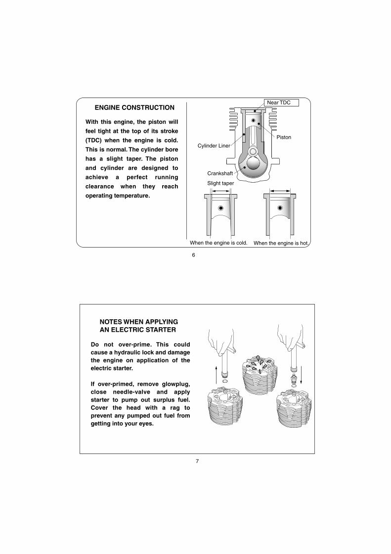
ENGINE CONSTRUCTION
With this engine, the piston will
feel tight at the top of its stroke
(TDC) when the engine is cold.
This is normal. The cylinder bore
has a slight taper. The piston
and cylinder are designed to
achieve a perfect running
clearance when they reach
operating temperature.
Near TDC
Slight taper
When the engine is cold. When the engine is hot.
7
NOTES WHEN APPLYINGAN ELECTRIC STARTER
Do not over-prime. This could cause a hydraulic lock and damage the engine on application of the electric starter.
If over-primed, remove glowplug, close needle-valve and apply starter to pump out surplus fuel. Cover the head with a rag to prevent any pumped out fuel from getting into your eyes.

8
Standard accessories
Glow Plug LC3
Exhaust Seal Ring 1piece
ABOUT THE ENGINE
Exhaust Manifold for Revo
Items necessary for starting
Tools, accessories, etc.The following items are necessary for operating the engine.
BEFORE STARTING
FUELGenerally, it is suggested that the user selects a fuel that is commercially available for model two-stroke engines and contains 10-30% nitromethane. As a starting point, we recommend a fuel containing 20% nitromethane, changing to a fuel containing more nitro if necessary. When the brand of fuel is changed, or the nitro content increased, it is advisable to repeat the running-in procedure referred to in the RUNNING-IN paragraphs. Please note that with high-nitro fuels, although power may be increased for competition purposes, glowplug elements do not last as long and engine life will be shortened.
T-Maxx and Revo are trademarks of Traxxas Corp.
Exhaust Manifold for T-Maxx
These engines are designed especially to power the T-Maxx or Revo. Purposely designed LC3 glow plug is supplied with the engine for improved power, fuel economy and durability. The carburetor offers easy handling as well as high performance.
9
!
!
Model engine fuel is poisonous. Do not allow it to come into contact with the eyes or mouth. Always store it in a clearly marked container and out of the reach of children.
Model engine fuel is also highly flammable. Keep it away from open flame, excessive heat, sources of sparks, or anything else which might ignite it. Do not smoke or allow anyone else to smoke, near to it.
FUEL FILTER
GLOWPLUG IGNITERCommercialy available handy glowplug heater in which the glowplug battery and battery leads are integrated.
To be installed in the fuel line between fuel tank and carburetor to prevent foreign matter from entering the carburetor.
FUEL PUMP
For filling the fuel tank, a simple, polyethylene "squeeze" bottle, with a suitable spout, is required.
SILICONE FUEL LINEHeatproof silicone tubing of approx. 5mm o.d. and 2mm i.d. is required for the connection between the fuel tank and engine.
10
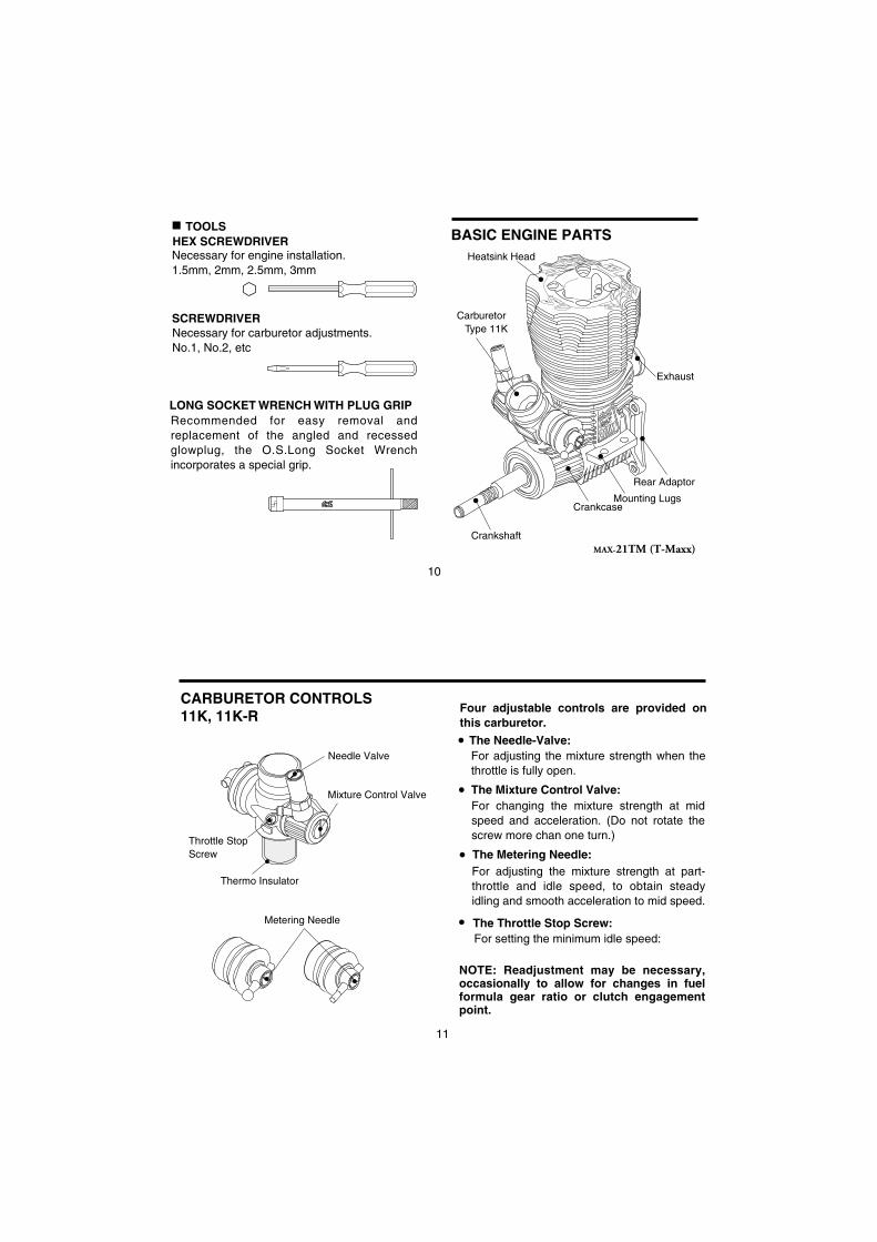
TOOLSHEX SCREWDRIVER
SCREWDRIVER
Necessary for engine installation.1.5mm, 2mm, 2.5mm, 3mm
Necessary for carburetor adjustments.No.1, No.2, etc
LONG SOCKET WRENCH WITH PLUG GRIPRecommended for easy removal and replacement of the angled and recessed glowplug, the O.S.Long Socket Wrench incorporates a special grip.
Heatsink Head
CrankcaseMounting Lugs
Exhaust
Carburetor Type 11K
Crankshaft
Rear Adaptor
BASIC ENGINE PARTS
MAX-21TM (T-Maxx)
11
CARBURETOR CONTROLS11K, 11K-R
The Needle-Valve:
The Mixture Control Valve:
Four adjustable controls are provided on this carburetor.
For adjusting the mixture strength when the throttle is fully open.
For changing the mixture strength at mid speed and acceleration. (Do not rotate the screw more chan one turn.)
The Throttle Stop Screw:For setting the minimum idle speed:
For adjusting the mixture strength at part-throttle and idle speed, to obtain steady idling and smooth acceleration to mid speed.
The Metering Needle:
NOTE: Readjustment may be necessary, occasionally to allow for changes in fuel formula gear ratio or clutch engagement point.
Metering Needle
Throttle StopScrew
Mixture Control Valve
Needle Valve
Thermo Insulator

12
FACTS ABOUT GLOWPLUGS
The role of the glowplug
Glowplug lifeParticularly in the case of very high performance engines, glowplugs must be regarded as expendable items.
With a glowplug engine, ignition is initiated by the application of a 1.5-volt power source. When the battery is disconnected, the heat retained within the combustion chamber remains sufficient to keep the plug filament glowing, thereby continuing to keep the engine running. Ignition timing is 'automatic' : under reduced load, allowing higher rpm, the plug becomes hotter and, appropriately, fires the fuel/air charge earlier; conversely, at reduced rpm, the plug become cooler and ignition is retarded.
Since the compatibility of glowplug and fuel may have a marked effect on performance and reliability, it may be worthwhile to choose the R/C type plug found most suitable after tests. Recommended O.S. plugs are LC3. Carefully install plug finger-tight, before final tightening with the correct size plug wrench.
Install a plug suitable for the engine.
Use fuel containing a moderate percentage of nitromethane.
Do not run the engine too lean and do not leave the battery connected while adjusting the needle.
However, plug life can be extended and engine performance maintained by careful use, i.e.:
Apart from when actually burned out, a plug may need to be replaced because it no longer delivers its best performance, such as when:
When to replace the glowplug
Filament surface has roughened and turned white.
Filament coil has become distorted.
Foreign matter has adhered to filament or plug body has corroded.
Engine tends to cut out when idling.
Starting qualities deteriorate.
13
INSTALLATION
First, remove the original engine, from the engine mount.
Install the flywheel and clutch.
Install the engine on the engine mount with ground wire.

14
Install the electric starter taken from the original engine.
Install the manifold supplied with the engine.
T-Maxx Revo
15
Adjust the stopper end so that the throttle linkage may be made correctly.
Adjust the plastic ball end so that the throttle linkage may be connected correctly.
T-Maxx Revo

16
Finally, connect the wire for glow plug heating to the glow plug.
Finally, insert the wire for heating the glow plug.
T-MaxxRevo
17
For long life and high performance, every engine needs to be 'run-in' or 'broken-in'. With care, running-in of the MAX-21TM can be carried out with the engine installed in the vehicle. Be sure to install the air-cleaner on the carburetor and use a muffler-pressurized fuel system.
STARTING THE ENGINE & RUNNING-IN ('Breaking-in')
Fill the tank completely with fuel.
The somewhat violent changes of vehicle attitude that occur in off-road running, combined with the fact that, in buggy type cars, the fuel tank is often located some distance from the carburetor, means that fuel 'head' at the carburetor can vary and upset running.Therefore,it is recommended that a muffler pressurized fuel feed system be used.
Never run your vehicle without installing the air cleaner. Dust and dirt that may otherwise be drawn into the engine will rapidly shorten its life.
Temporarily remove the glowplug to check that it glows bright red when energized.
Glow Plug Igniter
PliersElement glows when energized.
Replace the plug when the element does not glow or is burnt out.

18
Remember!It is vitally important to set the throttle at the correct position before attempting to start the engine. If the engine is allowed to run with the throttle too far open under "no load" conditions, it will rapidly overheat and may be seriously damaged.
When the engine starts, first allow it to operate in short runs on its very rich starting settings, with the glowplug battery still connected and with its driving wheels clear of the ground. The rich mixture will, under these conditions, provide adequate lubrication and cooling, indicated by profuse smoke from the exhaust.
Next, disconnect the glowplug battery and try running the car on the track. If the engine stalls, open the throttle fractionally, but try to keep the engine running as rich as possible: if it stops because of being excessively over-rich, close the Needle-Valve 30˚ and try again.Run the car on the track until one tank of fuel has been consumed, then close the Needle-Valve 30˚. Repeat this procedure again until five tanks of fuel have been consumed, during which time the throttle may be opened for brief bursts of increased power. If the engine stops at medium speeds, close the Mixture Control Valve 30˚.
The carburetor on this engine has been set at the starting setting when the engine leaves the factory.Switch on the transmitter, and check that all the linkage moves correctly.
30˚Needle
The position of the needle-valvewhen starting the engine.
Close the needle-valve approx.30˚ after running the vehicle forevery one full tanks of fuel.Repeat this procedure aroundfive times.
30˚
30˚
19
Note:If the engine should need to be disassem-bled (e.g. for cleaning or minor parts re-placement), it is advisable to return the nee-dle-valve to the original rich, starting set-ting and check whether further running-in time is required before the car is raced again. In the event of any major working parts (e.g. piston/cylinder liner assembly) being replaced or the fuel being changed, especially to high nitro fuel, the complete running-in should be repeated.
Fuel
Warning!Do not touch rotating parts, engine and si-lencer when stopping the engine as they become very hot, and contact with them may result in a serious burn.
To stop the engine, close the throttle to idle speed, then shut it off completely with the trim lever on the transmitter.To cut off the fuel supply, pinch the fuel delivery tube to the carburetor.

20
FINAL ADJUSTMENTRun the vehicle (with throttle fully open) over the longest available straight course, in order to observe the model's speed. Next return the car to the starting point, close the Needle-Valve 30˚ and repeat the run, taking note of the improvement in performance.
Continue with further runs, gradually reducing the Needle-Valve setting and aiming to achieve the highest straight-line speed. Remember, however, that, if the Needle-Valve is shut down too far, the engine will overheat and, accompanied by visibly diminished exhaust smoke, the model will lose speed. At this point, throttle down immediately, stop the vehicle and reopen the Needle-Valve 30˚.
Final adjustment should be carried out only after the running-in has been completed.
Throttle Stop Screw
Needle Valve
Metering Needle
Open CloseCloseOpen
Needle ValveMetering Needle
More fuel Less fuelMore fuel Less fuel
Type 11K
21
Warning!Mixture adjustments (whether via the Metering Needle, or the Needle-Valve) cannot be made accurately under 'no-load' conditions, which, in any case, are not advised, since such operation carries the risk of seriously damaging the engine through over-revving and overheating.
With the optimum mixture control position, light smoke is visible during high speed running,and the engine rpm increases smoothly during acceleration. Remember that, if the engine is operated with the fuel/air mixture slightly too lean, it will overheat and run unevenly. As with all engines, it is advisable to set both the needle-valve and metering needle slightly on the rich side of the best rpm setting, as a safety measure.
If the engine runs too fast with the throttle closed, the throttle stop screw should be turned counter-clockwise to allow the throttle opening to be reduced.
With the engine running, close the throttle and allow it to idle for about five seconds, then reopen the throttle fully. If, at this point, the engine puffs out an excessive amount of smoke and the vehicle does not accelerate smoothly and rapidly, it is probable that the idle mixture is too rich. In this case, turn the Metering Needle clockwise 30˚. If, on the other hand, the engine tends to speed up momentarily and then cut out abruptly when the throttle is opened, the idle mixture is too lean. Correct this by turning the Metering Needle counter-clockwise 30˚.
NOTE:Metering Needle adjustment should be made in steps of not more than 30˚, carefully checking the effect,on throttle response, of each small adjustment.
Carry out adjustments patiently, under actual running conditions, until the engine responds quickly and positively to the throttle control.

22
Finally, beyond the nominal break-in period, a slight readjustment toward a leaner needle setting may be required to maintain maximum performance.
CARBURETOR CLEANLINESSThe correct functioning of the carburetor depends on its small fuel orifices remaining clear.
REALIGNMENT OF METERING NEEDLE ANDMIXTURE CONTROL VALVE
In the course of making carburetor adjustments, it is just possible that the Metering Needle and the Mixture Control Valve may be inadvertently screwed in or out too far and thereby moved beyond its effective adjustment range.The basic positions can be found by rotating the Metering Needle until its slotted head is flush with the ball link body or throttle lever body.
Mixture Control ValveCarburetor Body
Slide Valve
Carburetor Body
Metering Needle
Rotate the Metering Needle until its slotted head is flush with the Throttle Lever body. This is the standard position.
First rotate the Mixture Control Valve until its slotted head is flush with the carburetor body. Then screw the valve in exactly 0.5 turn. This is the standard position.
Throttle Lever
Slide Valve
Carburetor Body
Metering Needle
Rotate the Metering Needle until its slotted head is flush with the ball link body. This is the standard position.
Ball Link11K
11K-R
23
CARE AND MAINTENANCE
1.
2.
3.The minute particles of foreign matter, that are present in any fuel may, by accumulating and partially obstructing fuel flow, cause engine performance to become erratic and unreliable.O.S. 'Super-Filters' (large and small) are available, as optional extras, to deal with this problem. One of these filters installed to the pickup tube inside your refueling container, will prevent the entry of foreign material into the fuel tank. It is also recommended that a good in-line filter be installed between the tank and carburetor.
Do not forget to clean the filters regularly to remove dirt and lint that accumulate on the filter screens. Also, clean the carburetor itself occasionally.
At the end of each operating session, drain out any fuel that may remain in the fuel tank. Afterwards,energize the glow-plug and try to restart the engine, to burn off any fuel that may remain inside the engine. Repeat this procedure until the engine fails to fire. Do this while the engine is still warm.
4. Then, inject some after-run oil into the engine, and rotate the engine with an electric starter for 4 to 5 seconds to distribute the oil to all the working parts.
Note:Do not inject after-run oil into the carburetor as this may cause the O-rings inside the carburetor to deteriorate. These procedures will reduce the risks of starting difficulties or corrosion after a period of storage.

24
Installing Dust CapsWhen storing the engine, install the cap on the exhaust port, carburetor, etc. to prevent dust from entering the engine.
5. Finally, when cleaning the exterior of the engine, use only methanol. Do not use gasoline, kerosene or any solvent that might damage the silicone fuel tubing.
Caution: The rear crankshaft bearing of this engine uses a special plastic retainer. If the front housing needs to be heated to remove or replace the bearing, do not allow the bearing to exceed 120˚C (248˚F), otherwise it may be damaged and rendered unserviceable.
Dirt and dust may lodge in marked places.
(Optional extra)
25
CHECKING THE ENGINEIf the engine suffers a loss of performance after a long period of running it may be due to the wearing of parts. It is suggested that the worn parts be replaced when the following symptoms are detected.
Engine sound changes and easily overheats.
Power has dropped considerably.
Idle is unstable and/or engine tends to stop at idle.
In most cases, ball bearings, cylinder & piston assembly, connecting rod and/or crankcase have become worn out or abnormal. Check the parts carefully and replace them if necessary.

26
TROUBLE SHOOTING
Symptom
Cause Corrective action
Engine fails to fire.
Fuel tank is empty.Fuel not reaching the engine.
Fill the tank with fuel and repeatPriming procedure.
Glowplug element is burnt out.Glowplug battery discharged
Replace glowplug.Recharge or replace the battery.
Clogged fuel filterAir cleaner and silencer inside is dirty.
Clean or replace fuel filter.Replace cleaner element and clean inside silencer.
Over priming Remove glowplug and pump out excess fuel.
Fuel tubing is disconnected. Connect fuel tubing securely.Fuel tubing is kinked, split or has a hole. Check the tubing carefully and replace if necessary.
Incorrect servo linkage Connect correctly after setting servo at neutral.
Reverse rotating direction of starter box. Mare sure it rotates counter clockwise seen from crankshaft side.
27
Symptom
Cause Corrective action
Engine fires intermittently but does not run.
Insufficient fuel in the tank. Fill the tank with fuel.
Deteriorated glowplug Replace glowplug.
Clogged fuel filterAir cleaner and silencer inside is dirty.
Clean or replace fuel filter.Replace cleaner element and clean inside silencer.
Engine overheated Wait until engine is cool.
Incorrect clutch release Adjust the tension of clutch spring.
Starting battery disconnected too soon.Do not disconnect plug battery and wait untilr.p.m. becomes stable.
Vibration causing air bubbles in fuel.Install "O" rings to the tank screws to prevent bubbles.
28
Symptom
Cause Corrective action
Symptom
Cause Corrective action
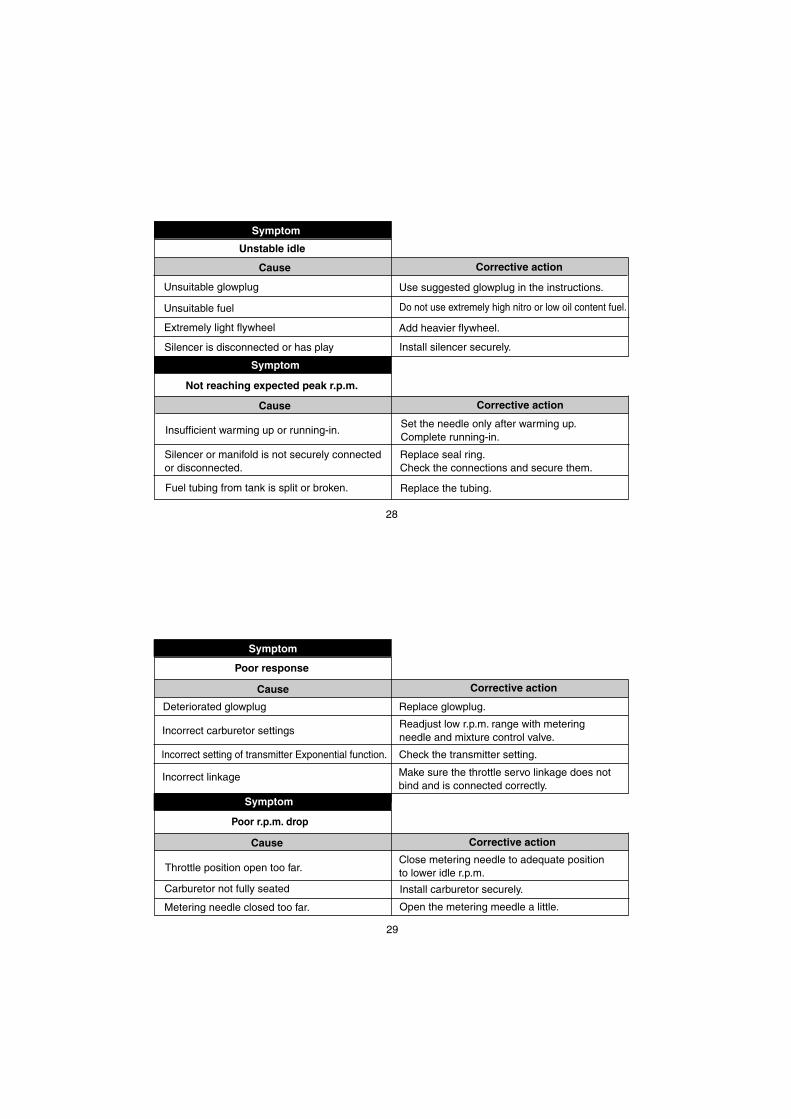
Unstable idle
Unsuitable glowplug Use suggested glowplug in the instructions.
Unsuitable fuel Do not use extremely high nitro or low oil content fuel.
Extremely light flywheel Add heavier flywheel.
Silencer is disconnected or has play Install silencer securely.
Not reaching expected peak r.p.m.
Insufficient warming up or running-in.Set the needle only after warming up. Complete running-in.
Silencer or manifold is not securely connectedor disconnected.
Replace seal ring. Check the connections and secure them.
Fuel tubing from tank is split or broken. Replace the tubing.
29
Symptom
Cause Corrective action
Symptom
Cause Corrective action
Poor response
Deteriorated glowplug Replace glowplug.
Incorrect carburetor settingsReadjust low r.p.m. range with metering needle and mixture control valve.
Incorrect setting of transmitter Exponential function. Check the transmitter setting.
Poor r.p.m. drop
Throttle position open too far.Close metering needle to adequate positionto lower idle r.p.m.
Carburetor not fully seated Install carburetor securely.
Incorrect linkage Make sure the throttle servo linkage does notbind and is connected correctly.
Metering needle closed too far. Open the metering meedle a little.

30
21T
M (
T-M
axx)
EN
GIN
E E
XP
LO
DE
D V
IEW
Typ
e of
scr
ew C…
Cap
Scr
ew M…
Ova
l Fill
iste
r-H
ead
Scr
ewF…
Fla
t Hea
d S
crew
N…
Rou
nd H
ead
Scr
ew S…
Set
Scr
ew
*
C.M
3x16
1
2
3
5
4
6
7
8
9 10
11
12
14
13
15
17
M.+
M2.
6x7
16
31
21T
M (
T-M
axx)
EN
GIN
E P
AR
TS
LIS
T
The
spe
cific
atio
ns a
re s
ubje
ct to
alte
ratio
n fo
r im
prov
emen
t with
out n
otic
e.
7987
1160
2191
4200
2192
1400
2191
3300
2390
6000
2181
7000
2191
5000
2198
2000
2538
1701
2373
1000
2192
1000
2193
1000
2191
2000
2192
2000
2192
1800
2191
1800
7986
0070
7165
3000
2142
7200
7210
3800
7210
6172
1 2 3 4 5 6 7 8 9 10 11 12 13 14 15 16 17
Cyl
inde
r H
ead
Ret
aini
ng S
crew
(10
pcs.
)H
eats
ink
Hea
dH
ead
Gas
ket (
1pc.
)C
ylin
der
& P
isto
n A
ssem
bly
Pis
ton
Pin
Pis
ton
Pin
Ret
aine
r (2
pcs.
)C
onne
ctin
g R
odC
arbu
reto
r C
ompl
ete
(Typ
e 11
K)
Car
bure
tor
Ret
aine
rC
rank
shaf
t Bal
l Bea
ring
(Fro
nt)
Cra
nkca
seC
rank
shaf
t Bal
l Bea
ring
(Rea
r)C
rank
shaf
tS
tart
ing
Sha
ftC
over
Gas
ket
Rea
r A
dapt
orR
ear
Ada
ptor
Ret
aini
ng S
crew
(10
pcs.
)G
low
Plu
g LC
3E
xhau
st S
eal R
ing
(2pc
s.)
Exh
aust
Man
ifold
M10
20M
anifo
ld S
prin
g (2
pcs.
)
Des
crip
tio
nC
od
e N
o.
No
.
32
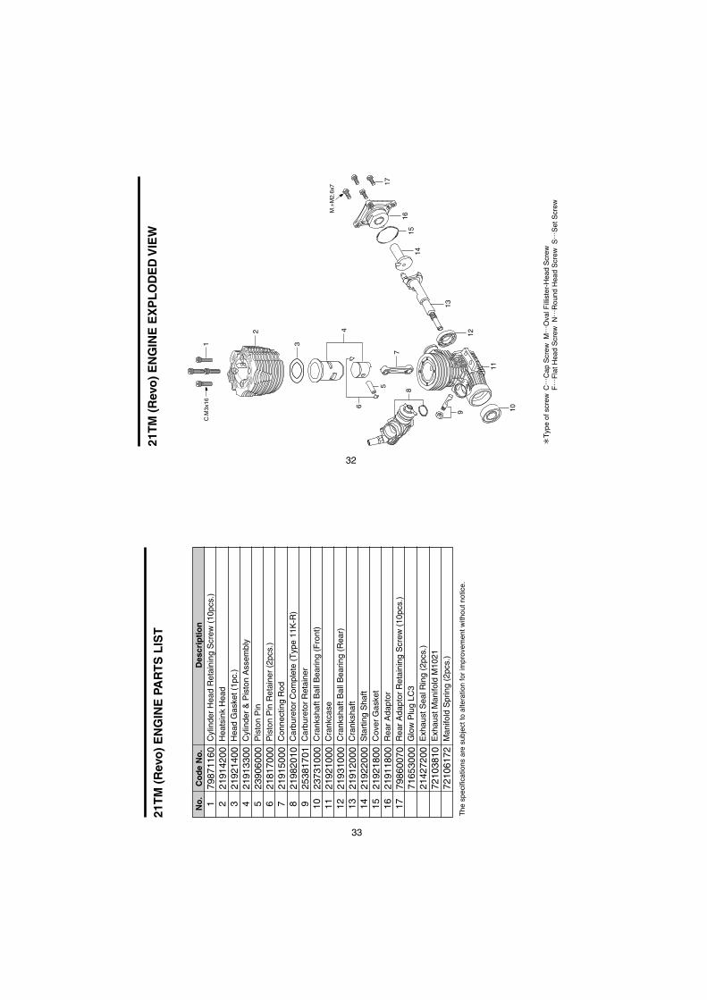
21T
M (
Rev
o)
EN
GIN
E E
XP
LO
DE
D V
IEW
Typ
e of
scr
ew C…
Cap
Scr
ew M…
Ova
l Fill
iste
r-H
ead
Scr
ewF…
Fla
t Hea
d S
crew
N…
Rou
nd H
ead
Scr
ew S…
Set
Scr
ew
*
C.M
3x16
1
2
3
5
4
6
7
8
9 10
11
12
14
13
15
17
M.+
M2.
6x7
16
33
21T
M (
Rev
o)
EN
GIN
E P
AR
TS
LIS
T
The
spe
cific
atio
ns a
re s
ubje
ct to
alte
ratio
n fo
r im
prov
emen
t with
out n
otic
e.
7987
1160
2191
4200
2192
1400
2191
3300
2390
6000
2181
7000
2191
5000
2198
2010
2538
1701
2373
1000
2192
1000
2193
1000
2191
2000
2192
2000
2192
1800
2191
1800
7986
0070
7165
3000
2142
7200
7210
3810
7210
6172
1 2 3 4 5 6 7 8 9 10 11 12 13 14 15 16 17
Cyl
inde
r H
ead
Ret
aini
ng S
crew
(10
pcs.
)H
eats
ink
Hea
dH
ead
Gas
ket (
1pc.
)C
ylin
der
& P
isto
n A
ssem
bly
Pis
ton
Pin
Pis
ton
Pin
Ret
aine
r (2
pcs.
)C
onne
ctin
g R
odC
arbu
reto
r C
ompl
ete
(Typ
e 11
K-R
)C
arbu
reto
r R
etai
ner
Cra
nksh
aft B
all B
earin
g (F
ront
)C
rank
case
Cra
nksh
aft B
all B
earin
g (R
ear)
Cra
nksh
aft
Sta
rtin
g S
haft
Cov
er G
aske
tR
ear
Ada
ptor
Rea
r A
dapt
or R
etai
ning
Scr
ew (
10pc
s.)
Glo
w P
lug
LC3
Exh
aust
Sea
l Rin
g (2
pcs.
)E
xhau
st M
anifo
ld M
1021
Man
ifold
Spr
ing
(2pc
s.)
Des
crip
tio
nC
od
e N
o.
No
.

34
S.M3x3
1
1-11-2
2
2-1
2-2
3
4
8
9
10
5 6
6-1
7
3-1
11K CARBURETOR EXPLODED VIEW
Type of screw
C...Cap Screw M...Oval Fillister-Head ScrewF...Flat Head Screw N...Round Head Screw S...Set Screw
35
The specifications are subject to alteration for improvement without notice.
11K CARBURETOR PARTS LIST
11-11-22
2-12-23
3-1456
6-178910
DescriptionCode No.No.
22615000
227818002788182021982700
21982620
2788182021285901
219821002198220021982540
2198252023818430
21881950
22781800
Carburetor Rubber Gasket
Ball Link No.5
Dust Cover
Metering Needle AssemblySlide Valve
No.14 Universal Nipple Assembly
Carburetor Body (w/Thermo Insulator)
"O" Ring (2pcs.)Needle Valve Assembly
Throttle Stop Screw
"O" Ring (S) (2pcs.)"O" Ring (L) (2pcs.)
Mixture Control Valve Assembly
"O" Ring (S) (2pcs.)
Thermo Insulator21982900
22781800 "O" Ring (S) (2pcs.)

36
11K-R CARBURETOR EXPLODED VIEW
Type of screw
C...Cap Screw M...Oval Fillister-Head ScrewF...Flat Head Screw N...Round Head Screw S...Set Screw
S.M3x3
1
1-11-2
2
2-1
2-2
3
4
8
9
10
5 6
6-1
7
3-1
37
The specifications are subject to alteration for improvement without notice.
11K-R CARBURETOR PARTS LIST
11-11-22
2-12-23
3-1456
6-178910
DescriptionCode No.No.
22615000
227818002788182021982700
21982620
2788182021285901
219821002198220021982540
2198252023818440
21881950
22781800
Carburetor Rubber Gasket
Throttle Lever
Dust Cover
Metering Needle AssemblySlide Valve
No.14 Universal Nipple Assembly
Carburetor Body (w/Thermo Insulator)
"O" Ring (2pcs.)Needle Valve Assembly
Throttle Stop Screw
"O" Ring (S) (2pcs.)"O" Ring (L) (2pcs.)
Mixture Control Valve Assembly
"O" Ring (S) (2pcs.)
Thermo Insulator21982900
22781800 "O" Ring (S) (2pcs.)

38
RACING ENGINE PARTS
(71653000)LC3
(72106172)
3 (73300305)
7 (73300712)
12 (73301212)
Dust Cap Set
For Carburetor Nipple
For Silencer
For Carburetor
Long Socket WrenchWith Plug Grip(71521000)
O.S. Glow Plug
(21427200)
Exhaust Seal Ring (2pcs.)
Manifold Spring (2pcs.)
O.S. GENUINE PARTS & ACCESSORIES
The specifications are subject to alteration for improvement without notice.
39
3.41cc (0.208 cu.in.)17.0mm (0.669 in.)15.0mm (0.590 in.)3,000-35,000 r.p.m.1.8 ps / 29,000 r.p.m.243g (8.57 oz.)
■ ■ ■ ■ ■ ■
Displacement Bore Stroke Practical R.P.M. Power output Weight
SPECIFICATIONS
21TM (T-Maxx) THREE VIEW DRAWING
Dimensions (mm)
JAPAN
JAPAN
34.826.3 18.8
M7x1
31.4
11
39
4- 3.3
85.3
6
6
25.4
16

40
■ ■ ■ ■ ■ ■
Displacement Bore Stroke Practical R.P.M. Power output Weight
SPECIFICATIONS
21TM (Revo) THREE VIEW DRAWING
Dimensions (mm)
JAPAN
JAPAN
34.826.3 18.8
M7x1
31.4
11
39
4- 3.3
85.3
6
6
25.4
16
3.41cc (0.208 cu.in.)17.0mm (0.669 in.)15.0mm (0.590 in.)3,000-35,000 r.p.m.1.8 ps / 29,000 r.p.m.243g (8.57 oz.)
C Copyright 2007 by O.S.Engines Mfg. Co., Ltd. All rights reserved. Printed in Japan. 60091960 010903
TEL. (06) 6702-0225FAX. (06) 6704-2722
6-15 3-Chome Imagawa Higashisumiyoshi-ku Osaka 546-0003, Japan
URL : http://www.os-engines.co.jp