51sPACE WAGON
54
51-1 EXTERIOR CONTENTS 51109000210 FRONT BUMPER 2 .................... SPECIAL TOOL 2 ......................... FRONT BUMPER 3 ........................ REAR BUMPER 7 ..................... SPECIAL TOOL 7 ......................... REAR BUMPER 8 ......................... RADIATOR GRILLE 12 ................ ROOF RAIL 13 ........................ MOULDING AND GARNISH 14 ......... SEALANT AND ADHESIVE 14 ............. SPECIAL TOOLS 14 ...................... MOULDING AND GARNISH 15 ............ AERO P ARTS 20 ...................... SEALANT AND ADHESIVE 20 ............. SPECIAL TOOL 20 ....................... AERO PARTS 20 ......................... WINDSHIELD WIPER AND WASHER 23 .......................... SERVICE SPECIFICATIONS 23 ............ SPECIAL TOOLS 23 ...................... TROUBLESHOOTING 24 .................. WI NDSHIE LD WI P ER AND WASH ER 30 ... REAR WIPER AND WASHER 34 ....... SPECIAL TOOLS 34 ...................... TROUBLESHOOTING 34 .................. REAR WIPER AND WASHER 39 .......... HEADLAMP WASHER 42 .............. SPECIAL TOOLS 42 ...................... TROUBLESHOOTING 42 .................. HEADLAMP WASHER 45 ................. MARKS 47 ............................ DOOR MIRROR 50 ....................
-
Upload
rafaelcruzgja -
Category
Documents
-
view
224 -
download
0
Transcript of 51sPACE WAGON

8/16/2019 51sPACE WAGON
http://slidepdf.com/reader/full/51space-wagon 1/54
51-1
EXTERIOR
CONTENTS 51109000210
FRONT BUMPER 2. . . . . . . . . . . . . . . . . . . .
SPECIAL TOOL 2. . . . . . . . . . . . . . . . . . . . . . . . .
FRONT BUMPER 3. . . . . . . . . . . . . . . . . . . . . . . .
REAR BUMPER 7. . . . . . . . . . . . . . . . . . . . .
SPECIAL TOOL 7. . . . . . . . . . . . . . . . . . . . . . . . .
REAR BUMPER 8. . . . . . . . . . . . . . . . . . . . . . . . .
RADIATOR GRILLE 12. . . . . . . . . . . . . . . .
ROOF RAIL 13. . . . . . . . . . . . . . . . . . . . . . . .
MOULDING AND GARNISH 14. . . . . . . . .
SEALANT AND ADHESIVE 14. . . . . . . . . . . . .
SPECIAL TOOLS 14. . . . . . . . . . . . . . . . . . . . . .
MOULDING AND GARNISH 15. . . . . . . . . . . .
AERO PARTS 20. . . . . . . . . . . . . . . . . . . . . .
SEALANT AND ADHESIVE 20. . . . . . . . . . . . .
SPECIAL TOOL 20. . . . . . . . . . . . . . . . . . . . . . .
AERO PARTS 20. . . . . . . . . . . . . . . . . . . . . . . . .
WINDSHIELD WIPER AND
WASHER 23. . . . . . . . . . . . . . . . . . . . . . . . . .
SERVICE SPECIFICATIONS 23. . . . . . . . . . . .
SPECIAL TOOLS 23. . . . . . . . . . . . . . . . . . . . . .
TROUBLESHOOTING 24. . . . . . . . . . . . . . . . . .
WINDSHIELD WIPER AND WASHER 30. . .
REAR WIPER AND WASHER 34. . . . . . .
SPECIAL TOOLS 34. . . . . . . . . . . . . . . . . . . . . .
TROUBLESHOOTING 34. . . . . . . . . . . . . . . . . .
REAR WIPER AND WASHER 39. . . . . . . . . .
HEADLAMP WASHER 42. . . . . . . . . . . . . .
SPECIAL TOOLS 42. . . . . . . . . . . . . . . . . . . . . .
TROUBLESHOOTING 42. . . . . . . . . . . . . . . . . .
HEADLAMP WASHER 45. . . . . . . . . . . . . . . . .
MARKS 47. . . . . . . . . . . . . . . . . . . . . . . . . . . .
DOOR MIRROR 50. . . . . . . . . . . . . . . . . . . .

8/16/2019 51sPACE WAGON
http://slidepdf.com/reader/full/51space-wagon 2/54
EXTERIOR - Front Bumper51-2
FRONT BUMPER
SPECIAL TOOL 51100060071
Tool Number Name Use
MB990784 Ornament remover Removal of front bumper assembly

8/16/2019 51sPACE WAGON
http://slidepdf.com/reader/full/51space-wagon 3/54
EXTERIOR - Front Bumper 51-3
FRONT BUMPER 51100140201
REMOVAL AND INSTALLATION
Pre-removal and Post-installation OperationD Splash Shield Removal and Installation
(Refer to GROUP 42 - Fender.)D Radiator Grille Removal and Installation
(Refer to P.51-12.)
<SPACE RUNNER>
1
2
4
3
5
3
Section A - A
A
A
Clip
Pin
6
6
Removal steps
1. License plate bracket assembly2. Front turn signal lamp assembly
AA" 3. Front bumper assembly4. Front bumper lower bracket
assembly
5. Bumper garnish bracket assembly6. License plate bracket

8/16/2019 51sPACE WAGON
http://slidepdf.com/reader/full/51space-wagon 4/54
EXTERIOR - Front Bumper51-4
<SPACE WAGON>
23
5
4
6
1
Section A - A
A
A
Clip
Pin
6
5
Removal steps
1. License plate bracket assembly2. Fog lamp3. Fog lamp bezel <Vehicles without
fog lamp>
4. Front turn signal lamp assemblyAA" 5. Front bumper assembly
6. License plate bracket
REMOVAL SERVICE POINT
AA" FRONT BUMPER ASSEMBLY REMOVAL
1. Use the special tool to pull up the centre pin in the clip.2. Remove the clip.
MB990784
Pin MB990784
Clip
8/16/2019 51sPACE WAGON
http://slidepdf.com/reader/full/51space-wagon 5/54
EXTERIOR - Front Bumper 51-5
DISASSEMBLY AND REASSEMBLY 51100160238
<SPACE RUNNER>
3
6
2
5
41
Section A - A
Clip
Pin
Section B - B Section C - C
Clip
Clip
A
A
B
B
C
C
1
6
6
2
4
6
Disassembly steps1. Front bumper side plate2. Front bumper upper reinforcement3. Front bumper side net
4. Front air dam5. Bumper net
AA" 6. Front bumper face

8/16/2019 51sPACE WAGON
http://slidepdf.com/reader/full/51space-wagon 6/54
EXTERIOR - Front Bumper51-6
<SPACE WAGON>
3 6
2
5
4
1
Section A - A
Clip
Pin
Section B - B Section C - C
Clip
Clip
Section D - D Section E - E
Pin
Pin Pin
Clip
ClipSplashshield
78
A
A
B
B
C
C
D D
E
E
1
8
3
8
8
2
8
6
8
6
Disassembly steps
1. Front bumper side plate2. Front bumper upper reinforcement3. Front bumper lower bracket4. Front bumper protection moulding
5. Fog lamp bracket6. Front air dam7. Bumper net
AA" 8. Front bumper face

8/16/2019 51sPACE WAGON
http://slidepdf.com/reader/full/51space-wagon 7/54
EXTERIOR - Front Bumper/Rear Bumper 51-7
DISASSEMBLY SERVICE POINT
AA" FRONT BUMPER FACE REMOVAL
1. Use the special tool to pull up the centre pin in the clip.2. Remove the clip.
REAR BUMPER
SPECIAL TOOL 51100060071
Tool Number Name Use
MB990784 Ornament remover Removal of rear bumper assembly
MB990784
Pin
MB990784
Clip

8/16/2019 51sPACE WAGON
http://slidepdf.com/reader/full/51space-wagon 8/54
EXTERIOR - Rear Bumper51-8
REAR BUMPER 51100140201
REMOVAL AND INSTALLATION
<SPACE RUNNER>
1
2
4
3
5
3 Pin
Section A - A
A
A
Clip
Section B - B Section C - C Section D - D
Clip
Quarterinnerpanel
Clip
Clip
6
B
B
C
D
D
21
4
3
6
3
C
Removal steps
1. Rear mud guard2. Rear splash shield3. Rear bumper assembly
4. Rear bumper reinforcement5. Rear center bracket6. Rear bumper lower bracket

8/16/2019 51sPACE WAGON
http://slidepdf.com/reader/full/51space-wagon 9/54
EXTERIOR - Rear Bumper 51-9
<SPACE WAGON>
1 2
4
3
1
3
Pin
Section A - A
A
A
Clip
Section B - B
Clip
Quarterinnerpanel
2
B
B
Removal steps
1. Rear mud guard2. Rear splash shield
AA" 3. Rear bumper assembly4. Rear bumper reinforcement
REMOVAL SERVICE POINT
AA"REAR BUMPER ASSEMBLY REMOVAL <SPACEWAGON>
Two bolts (one bolt at either side) of the rear bumper assemblyinstallation bolts must be removed through the service holein the quarter trim.
Bolt
Quarter trim

8/16/2019 51sPACE WAGON
http://slidepdf.com/reader/full/51space-wagon 10/54
EXTERIOR - Rear Bumper51-10
DISASSEMBLY AND REASSEMBLY 51100160238
<SPACE RUNNER>
3
4
2
1
4
1
Section A - A
Clip
Section B - B
Clip
A
A
B
B
4
3
Disassembly steps
1. Rear bumper side plate2. Rear air dam
AA" 3. Rear bumper face4. Rear bumper garnish

8/16/2019 51sPACE WAGON
http://slidepdf.com/reader/full/51space-wagon 11/54
EXTERIOR - Rear BumperEXTERIOR - Rear Bumper 51-11
<SPACE WAGON>
3
2
4
1
Section A - A
Clip
Section B - B
Clip
Pin
A
A
B
B
1
4
4
3
Disassembly steps
1. Rear bumper side plate2. Corner protector
3. Rear air damAA" 4. Rear bumper face
DISASSEMBLY SERVICE POINT
AA"REAR BUMPER FACE REMOVAL
1. Use the special tool to pull up the centre pin in the clip.2. Remove the clip.
MB990784
Pin
MB990784
Clip
8/16/2019 51sPACE WAGON
http://slidepdf.com/reader/full/51space-wagon 12/54
EXTERIOR - Radiator Grille51-12
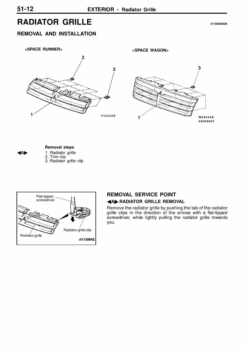
RADIATOR GRILLE 51100280026
REMOVAL AND INSTALLATION
1
2
3
1
3
<SPACE RUNNER> <SPACE WAGON>
Removal steps
AA" 1. Radiator grille2. Trim clip3. Radiator grille clip
REMOVAL SERVICE POINT
AA"RADIATOR GRILLE REMOVAL
Remove the radiator grille by pushing the tab of the radiatorgrille clips in the direction of the arrows with a flat-tippedscrewdriver, while lightly pulling the radiator grille towardsyou.
Flat-tippedscrewdriver
Radiator grille clip
Radiator grille

8/16/2019 51sPACE WAGON
http://slidepdf.com/reader/full/51space-wagon 13/54
EXTERIOR - Roof Rail 51-13
ROOF RAIL 51101660010
REMOVAL AND INSTALLATION
Pre-removal and Post-installation OperationHeadlining Removal and Installation
Roof rail

8/16/2019 51sPACE WAGON
http://slidepdf.com/reader/full/51space-wagon 14/54
EXTERIOR - Moulding and Garnish51-14
MOULDING AND GARNISH 51100470157
SEALANT AND ADHESIVE 51100050207
Items Specified sealant and adhesive
Side protect moulding to body panel Adhesive tape:3M ATD part No.6382 or equivalent [7 mm width and 1.2 mm thickness]
Primer:3M ATD part No.8608 Super Fast Urethane Primer or equivalent and 3M ATDpart No.8609 Super Fast Urethane Primer or equivalent
SPECIAL TOOLS 51100060033
Tool Number Name Use
MB990784 Ornament remover Removal of rear wiper and washer switch anddoor mirror control switch.
MB990449 Window mouldingremover
Removal of roof drip moulding, etc.

8/16/2019 51sPACE WAGON
http://slidepdf.com/reader/full/51space-wagon 15/54
EXTERIOR - Moulding and Garnish 51-15
MOULDING AND GARNISH 51100060033
REMOVAL AND INSTALLATION
<SPACE RUNNER>
2
1
3
1
4
5
1
4, 5
Section A - A
Clip
Section B - B Section C - C
Clip
Clip
Windshield
A
A
B
B
CC
C
C
AA" "BA 1. Roof drip moulding2. Windshield upper moulding
(Refer to GROUP 42 - Windshield.)
AB" "AA 3. Side protect moulding4. Delta outer garnish5. Tailgate garnish

8/16/2019 51sPACE WAGON
http://slidepdf.com/reader/full/51space-wagon 16/54
EXTERIOR - Moulding and Garnish51-16
<SPACE WAGON>
2
1
3
5
4
5
1
4, 5
Section A - A
Clip
Section B - B Section C - C
Clip
Clip
Windshield
Section D - D
Slide bolt
Packing
B
B
C
1
C
C
AA
D
D
C
Nut
AA" "BA 1. Roof drip moulding2. Windshield upper moulding
(Refer to GROUP 42 - Windshield.)
AB" "AA 3. Side protect moulding4. Delta outer garnish5. Tailgate garnish

8/16/2019 51sPACE WAGON
http://slidepdf.com/reader/full/51space-wagon 17/54
EXTERIOR - Moulding and Garnish 51-17
<SPACE RUNNER>
Adhesive tape: double-sided tape [7 mm width and 1.2 mm thickness]
<SPACE WAGON>
Adhesive tape: double-sided tape [7 mm width and 1.2 mm thickness]

8/16/2019 51sPACE WAGON
http://slidepdf.com/reader/full/51space-wagon 18/54
EXTERIOR - Moulding and Garnish51-18
REMOVAL SERVICE POINT
AA" ROOF DRIP MOULDING REMOVAL
Use the special tool to lever out the moulding.
CautionIf the moulding has become warped, it should not bereused.
AB" SIDE PROTECT MOULDING REMOVAL
1. Attach protection tape all the way along the edges of the double-sided tape which is still adhering to the body.
2. Use a resin spatula to scrape off the double-sided tape.3. Peel off the protection tape.4. Wipe the body surface and clean it with a rag moistened
with isopropyl alcohol.
INSTALLATION SERVICE POINTS
"AA SIDE PROTECT MOULDING INSTALLATION
Double-sided tape affixing to the side protect moulding(when reusing)
1. Scrape off the double-sided tape with a resin spatulaor gasket scraper.
2. Wipe off the side protect moulding adhesion surface andclean it with a shop towel moistened with isopropyl alcohol.
3. Affix the specified double sided tape to the side protectmoulding. (Refer to P.51-17.)
Specified adhesive tape:Double-sided tape: 7 mm width and 1.2 mmthickness
MB990449
Protection tape
Double-sided tape
Double-sided tape
8/16/2019 51sPACE WAGON
http://slidepdf.com/reader/full/51space-wagon 19/54
EXTERIOR - Moulding and Garnish 51-19
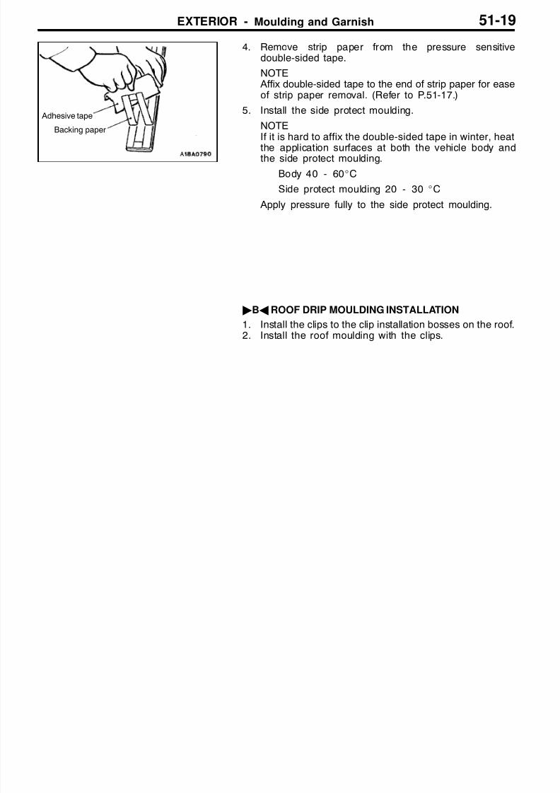
4. Remove strip paper from the pressure sensitivedouble-sided tape.
NOTE Affix double-sided tape to the end of strip paper for easeof strip paper removal. (Refer to P.51-17.)
5. Install the side protect moulding.
NOTE
If it is hard to affix the double-sided tape in winter, heatthe application surfaces at both the vehicle body andthe side protect moulding.
Body 40 - 60_C
Side protect moulding 20 - 30 _C
Apply pressure fully to the side protect moulding.
"BA ROOF DRIP MOULDING INSTALLATION
1. Install the clips to the clip installation bosses on the roof.2. Install the roof moulding with the clips.
Adhesive tape
Backing paper

8/16/2019 51sPACE WAGON
http://slidepdf.com/reader/full/51space-wagon 20/54
EXTERIOR - Aero Parts51-20
AERO PARTS 51100500184
SEALANT AND ADHESIVE 51100050207
Items Specified sealant and adhesive
Side air dam Adhesive tape:3M ATD part No.6382 or equivalent [5 mm width and 1.5 mm thickness]
Primer:3M ATD part No.8608 Super Fast Urethane Primer or equivalent and 3M ATDpart No.8609 Super Fast Urethane Primer or equivalent
SPECIAL TOOL 51100060033
Tool Number Name Use
MB990784 Ornament remover Removal of side air dam
AERO PARTS 51100060033
REMOVAL AND INSTALLATION
<SPACE RUNNER>
1
2
Section A - A
Grommet
1
AA
Tailgate spoiler removal steps
1. Tailgate spoilerD Tailgate upper trim (Refer to GROUP
42.)2. High-mounted stop lamp

8/16/2019 51sPACE WAGON
http://slidepdf.com/reader/full/51space-wagon 21/54
EXTERIOR - Aero Parts 51-21
<SPACE WAGON>
Adhesive tape: double-sided tape [5 mm width and 1.5 mm thickness]
1
1
Section A - A
Grommet
Section B - B Section C - C
2
ClipClip
Clip
A
A
B
B
CC
3 2
1
1
Side air dam removal steps
AA" "AA 1. Side air dam
Tailgate spoiler removal steps
2. Tailgate spoilerD Tailgate upper trim (Refer to GROUP
42.)3. High-mounted stop lamp
8/16/2019 51sPACE WAGON
http://slidepdf.com/reader/full/51space-wagon 22/54
EXTERIOR - Aero Parts51-22
REMOVAL SERVICE POINT
AA" SIDE AIR DAM REMOVAL
Remove the side air dam in the same manner as for theside protect moulding (Refer to P.51-18).
INSTALLATION SERVICE POINT
"AA SIDE AIR DAM INSTALLATION
Install the side air dam in the same manner as for the sideprotect moulding (Refer to P.51-18).

8/16/2019 51sPACE WAGON
http://slidepdf.com/reader/full/51space-wagon 23/54
EXTERIOR - Windshield Wiper and Washer 51-23
WINDSHIELD WIPER AND WASHER
SERVICE SPECIFICATIONS
Items Standard value
Parkposition of windshield wiper arm and Driver’s side 45 ± 5blade assembly (Distance between wiperblade and front deck garnish end) Passenger’s side 52 ± 5
SPECIAL TOOLS
Tool Number Name Use
MB991502 MUT-II subassembly
D Diagnosis code checkD ETACS-ECU input signal check
MB991529 Diagnosis codecheck harnessD
Diagnosis code checkD ETACS-ECU input signal check by using
a voltmeter

8/16/2019 51sPACE WAGON
http://slidepdf.com/reader/full/51space-wagon 24/54
EXTERIOR - Windshield Wiper and Washer51-24
TROUBLESHOOTING
DIAGNOSIS FUNCTION
INPUT SIGNAL INSPECTION PROCEDURE
1. Connect the MUT-II or a voltmeter to the diagnosis connector to check input signal. (Refer to GROUP00 - How to Use Troubleshooting/Inspection Service Points.)
2. The following input signals can be checked:Windshield wiper switchD LOD HID INTD Variable intermittent switchD MistWindshield washer switch
NOTEIf all the input signals cannot be check by using the MUT-II, the diagnosis circuit may be defective.
INSPECTION CHART FOR TROUBLE SYMPTOMS
Trouble symptom Inspectionprocedure
Referencepage
Communication with the MUT-II is impossible. Refer to GROUP 54 - SWS.
When the wiper switch is set to “LO” position, the wipers do not operates at “LO”mode.
1 51-25
When thewiper switchis set to “HI” position, thewipers donot operates at “LO” modeinstead of “HI” mode.
2 51-26
When the wiper switch is set to “INT” position, the wipers do not operateintermittently. (However, the wipers operate normally when the switch is set to “LO”or “HI” position.)
3 51-26
The wipers do not stop when the wiper switchisturned off during the low wiper speed. 4 51-27
The operating interval of the wipers does not change when the variable intermittentwiper switch is operated during constant vehicle speed.
5 51-27
The washers do not operate when the washer switch is operated. 6 51-28
Thewipers do notoperatewhen thewasher switchis operated (However, thewasheroperates normally.)
7 51-29

8/16/2019 51sPACE WAGON
http://slidepdf.com/reader/full/51space-wagon 25/54
EXTERIOR - Windshield Wiper and Washer 51-25
INSPECTION PROCEDURE FOR TROUBLE SYMPTOMS
Inspection Procedure 1
When the wiper switch is set to “LO” position, the wipersdo not operates at “LO” mode.
Probable cause
The cause may be a malfunction of the wiper switch input circuit, harness or connector,windshield wiper motor, back-up circuit or front-ECU.
D Malfunction of column switchD Malfunction of windshield wiper motorD Malfunction of wiring harness or connectorD Malfunction of front-ECU
Check trouble symptom.
OK
Check trouble symptom.NG
Check the harness wire between the front-ECU and the windshieldwiper motor, and repair if necessary.
OK
OK
Repair
MUT-II Self-Diag code Are any of the ETACS-ECU diagnosis codes output?
YESINSPECTION CHART FOR DIAGNOSIS CODES (Refer toGROUP 54 - SWS.)
OK
Measure at the front-ECU connector A-25X.D Disconnect the connector, and measure at the harness side.D Ignition switch: ACCD Voltage between terminal No.24 and earth
OK: System voltage
NGCheck the special fuse No.10.
NG
Replace
OK
Check trouble symptom.
NG
Check the harness wire between the ignition switch (ACC) andthe front-ECU, and repair if necessary.
Measure at the windshield wiper motor connector A-01.D Disconnect the connector, and measure at the harness side.D Continuity between terminal No.5 and earth
OK: Continuity
NG
OK
NG
Repair
MUT-II Input checkD Windshield wiper switch (LO)
NGCheck the windshield wiper and washer switch input circuit system.(Refer to P.51-29, INSPECTION PROCEDURE 8.)
NO
OK
Check the following connectors: B-89, B-103, B-66, A-25X
NG
Repair
Check the following connector: A-01
NG
NG
Check the harness wire between the windshield wiper motor andthe earth, and repair if necessary.
Check the following connector: A-01
NG
Replace the front-ECU.
Check trouble symptom.
Check the windshield wiper motor (Refer to P.51-32.)
OK
NG
Replace

8/16/2019 51sPACE WAGON
http://slidepdf.com/reader/full/51space-wagon 26/54
EXTERIOR - Windshield Wiper and Washer51-26
Inspection Procedure 2
When the wiper switch is set to “HI” position, the wipersdo not operates at “LO” mode instead of “HI” mode.
Probable cause
The cause may be a malfunction of the wiper switch input circuit, harness or connector,windshield wiper motor, back-up circuit or front-ECU.Fail-safe function may be active in the back-up circuit as the wipers operate at the“LO” mode.
D Malfunction of column switchD Malfunction of windshield wiper motorD Malfunction of wiring harness or connectorD Malfunction of front-ECU
OK
MUT-II Self-Diag code Are any of the ETACS-ECU diagnosis codes output?
YESINSPECTION CHART FOR DIAGNOSIS CODES (Refer toGROUP 54 - SWS.)
OK
Measure at the windshield wiper motor connector A-01.D Disconnect the connector, and measure at the harness side.D Ignition switch: OND Windshield wiper switch: HID Voltage between terminal No.2 and earth
OK: System voltage
NG
OK
Check trouble symptom.
NG
Check the harness wire between the front-ECU and the windshieldwiper motor, and repair if necessary.
MUT-II Input checkD Windshield wiper switch (HI)
NGCheck the windshield wiper and washer switch input circuit system.(Refer to P.51-29, INSPECTION PROCEDURE 8.)
NO
Check the following connectors: A-01, A-25X, A-28 <R.H. drivevehicles>
NG
Repair
NG
Replace the front-ECU.
Check trouble symptom.
Replace the windshield wiper motor.
OK
Inspection Procedure 3
When the wiper switch is set to “INT” position, the wipersdo not operate intermittently. (However, the wipers
operate normally when the switch is set to “LO” or “HI”position.)
Probable cause
The cause may be a malfunction of the wiper switch input circuit, harness or connector,windshield wiper motor, back-up circuit or front-ECU.The front-ECU can be normal as the wipers operate at the “LO” or “HI” mode.
D Malfunction of column switchD Malfunction of wiring harness or connectorD Malfunction of ETACS-ECU
MUT-II Self-Diag code Are any of the ETACS-ECU diagnosis codes output?
YESINSPECTION CHART FOR DIAGNOSIS CODES (Refer toGROUP 54 - SWS.)
OK
Check trouble symptom.
MUT-II Input checkD Windshield wiper switch (INT)
NGCheck the windshield wiper and washer switch input circuit system.(Refer to P.51-29, INSPECTION PROCEDURE 8.)
NO
Replace the ETACS-ECU.
OK

8/16/2019 51sPACE WAGON
http://slidepdf.com/reader/full/51space-wagon 27/54
EXTERIOR - Windshield Wiper and Washer 51-27
Inspection Procedure 4
The wipers do not stop when the wiper switch is turned offduring the low wiper speed.
Probable cause
Probably the front-ECU has stored the conditions before defects take place by afail-safe function as the windshield wiper motor was shorted or a malfunction occurredin the communication line during the wiper operation.
D Malfunction of column switchD Malfunction of windshield wiper motorD Malfunction of wiring harness or connectorD Malfunction of front-ECU
NG
Wiper operation checkDoes the wiper stop when the ignition switch is turned off?
NOCheck the windshield wiper motor (Refer to P.51-32.)
OK
MUT-II Self-Diag codeCheck the ETACS-ECU diagnosis codes.
OK
Check trouble symptom.
NG
Check the harness wire between the ignition switch (ACC) andthe windshield wiper motor, and repair if necessary.
Check trouble symptom.
YES
Check the following connectors: A-01, A-25X, B-66, B-103, B-89, A-28 <R.H. drive vehicles>
NG
Repair
INSPECTION CHART FOR DIAGNOSIS CODES (Refer toGROUP 54 - SWS.)
OK
Repair
Inspection Procedure 5
The operating interval of the wipers does not changewhen the variable intermittent wiper switch is operatedduring constant vehicle speed.
Probable cause
The cause may be a malfunction of the vehicle speed sensor input circuit, harnessor connector, column switch or ETACS-ECU.The front-ECU can be normal as the wipers operate at the “LO”, “HI” and “INT” mode.
D Malfunction of column switchD Malfunction of wiring harness or connectorD Malfunction of ETACS-ECU
MUT-II Self-Diag code Are any of the ETACS-ECU diagnosis codes output?
YESINSPECTION CHART FOR DIAGNOSIS CODES (Refer toGROUP 54 - SWS.)
OK
MUT-II Input checkD Windshield wiper switch (Variable intermittent wiper switch)
NG Replace the column switch.
NO
Replace the ETACS-ECU.

8/16/2019 51sPACE WAGON
http://slidepdf.com/reader/full/51space-wagon 28/54
EXTERIOR - Windshield Wiper and Washer51-28
Inspection Procedure 6
The washers do not operate when the washer switch isoperated.
Probable cause
The cause may be a malfunction of the vehicle speed sensor input circuit, harnessor connector, windshield washer motor or front-ECU.
D Malfunction of column switchD Malfunction of windshield washer motorD Malfunction of wiring harness or connectorD Malfunction of front-ECU
Check trouble symptom.
OK
Check trouble symptom.NG
Check the harness wire between the front-ECU and the windshieldwasher motor, and repair if necessary.
OK
OK
Repair
MUT-II Self-Diag code Are any of the ETACS-ECU diagnosis codes output?
YESINSPECTION CHART FOR DIAGNOSIS CODES (Refer toGROUP 54 - SWS.)
OK
Measure at the front-ECU connector A-25X.D Disconnect the connector, and measure at the harness side.D Ignition switch: ACCD Voltage between terminal No.24 and earth
OK: System voltage
NGCheck the special fuse No.10.
NG
Replace
OK
Check trouble symptom.
NG
Check the harness wire between the ignition switch (ACC) andthe front-ECU, and repair if necessary.
Measure at the windshield washer motor connector A-45.D Disconnect the connector, and measure at the harness side.D Continuity between terminal No.1 and earth
OK: Continuity
NG
OK
NG
Repair
MUT-II Input checkD Windshield washer switch
NGCheck the windshield wiper and washer switch input circuit system.(Refer to P.51-29, INSPECTION PROCEDURE 8.)
NO
OK
Check the following connectors: B-89, B-103, B-66, A-25X
NG
Repair
Check the following connector: A-45
NG
NG
Check the harness wire between the windshield washer motor
and the earth, and repair if necessary.
Check the following connector: A-45
NG
Replace the front-ECU.
Check trouble symptom.
Check the windshield washer motor (Refer to P.51-32.)
OK
NG
Replace

8/16/2019 51sPACE WAGON
http://slidepdf.com/reader/full/51space-wagon 29/54
EXTERIOR - Windshield Wiper and Washer 51-29
Inspection Procedure 7
The wipers do not operate when the washer switch isoperated (However, the washer operates normally.)
Probable cause
The cause may be a malfunction of harness or connector, windshield wiper motoror front-ECU.
D Malfunction of windshield wiper motorD Malfunction of wiring harness or connectorD Malfunction of front-ECU
Does the wiper operate when the windshield wiper switch is turnedon?
NO
INSPECTION PROCEDURE 1 (Refer to P.51-25.)
Replace the front-ECU.
YES
Inspection Procedure 8
Windshield wiper and washer switch input circuit check
OK
OK
Check the following connectors: B-89, B-91, B-87
NG
Repair
OK
OK
Measure at the column switch connector B-87.D Disconnect the connector, and measure at the harness side.
D Voltage between terminal No.1 and earthOK: System voltage
NGCheck the fusible link No.5 and the special fuse No.6.
NG
Replace
OK
Check trouble symptom.
NG
Check the harness wire between the fusible link No.5 and thecolumn switch, and repair if necessary.
OK
NG
OK
Check the following connectors:<L.H. drive vehicles> B-66, B-87, B-44, B-90, B-103<R.H. drive vehicles> B-66, B-87
NG
Repair
NG
Check the harness wire between the ignition switch (IG1) andthe column switch, and repair if necessary.
Check the following connector: B-87
OK
Replace the column switch.
Measure at the column switch connector B-87.D Disconnect the connector, and measure at the harness side.D Ignition switch: OND Voltage between terminal No.9 and earth
OK: System voltage
NGCheck the multipurpose fuse No.6.
Replace
NG
Measure at the column switch connector B-87.D Disconnect the connector, and measure at the harness side.D Continuity terminal No.4 and earth
OK: Continuity
NG
Repair
NG
Check the harness wire between the column switch and the earth,and repair if necessary.
Check trouble symptom.
Check trouble symptom.
OK
8/16/2019 51sPACE WAGON
http://slidepdf.com/reader/full/51space-wagon 30/54
EXTERIOR - Windshield Wiper and Washer51-30
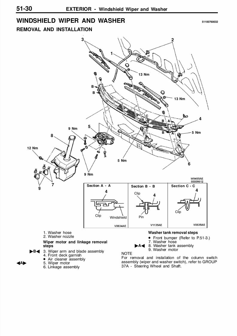
WINDSHIELD WIPER AND WASHER 51100760032
REMOVAL AND INSTALLATION
Section A - A Section B - B
WindshieldClip
3
13 Nm
4
2
4
9
A
A
B
B
7
6
8
4
1
5
4
Section C - C
Clip
Pin
Clip
13 Nm
C
C
B
B 5 Nm
5 Nm
9 Nm
9 Nm
12 Nm
1. Washer hose2. Washer nozzle
Wiper motor and linkage removalsteps
"BA 3. Wiper arm and blade assembly4. Front deck garnishD Air cleaner assembly
AA" 5. Wiper motor6. Linkage assembly
Washer tank removal steps
D Front bumper (Refer to P.51-3.)7. Washer hose
"AA 8. Washer tank assembly9. Washer motor
NOTEFor removal and installation of the column switchassembly (wiper and washer switch), refer to GROUP37A - Steering Wheel and Shaft.

8/16/2019 51sPACE WAGON
http://slidepdf.com/reader/full/51space-wagon 31/54
EXTERIOR - Windshield Wiper and Washer 51-31
REMOVAL SERVICE POINT
AA" WIPER MOTOR REMOVAL
1. Remove the wiper motor mounting bolts.2. Use a flat-tipped screwdriver to separate the wiper motor
crank arm from the linkage assembly, and then removethe wiper motor.
Caution
Because the installation angle of the crank arm andthe motor has been set, do not remove them unlessit is necessary to do so. If they must be removed,remove them only after marking their mountingpositions.
INSTALLATION SERVICE POINTS
"AA WASHER TANK ASSEMBLY INSTALLATION
When the washer tank assembly is reinstalled, make surethat the washer hoses and the control harness connectorsare connected to their original positions.
"BA WIPER ARM AND BLADE ASSEMBLYINSTALLATION
Install the wiper blade so that the wipers stops at the specifiedstop position (standard value) as shown in the illustration.
Standard value (A):<Driver’s side> 45 ± 5 mm<Passenger’s side> 52 ± 5 mm
Linkage assembly
Wiper motor crank arm
For rear washer (Black)
For frontwasher(White)
To rearwasher
To front washer
Front deck garnish end
AA

8/16/2019 51sPACE WAGON
http://slidepdf.com/reader/full/51space-wagon 32/54
EXTERIOR - Windshield Wiper and Washer51-32
INSPECTION 51100770035
WIPER MOTOR CHECK 51101260135
Disconnect the wiring harness connector, and then checkthe wiper motor operation with the wiper motor remaininginstalled to the body.
Wiper Motor Operation Speed
Connect a battery to the wiper motor as shown in the illustrationand check the operation speed.
Stop Position
1. Connect a battery to the wiper motor as shown in the(A) of the illustration. Then run the wiper motor at lowspeed, disconnect the battery, and stop the motor.
2. Connect the terminals via a jumper wire and a batteryto the wiper motor as shown in the (B) of the illustration.
After the motor starts turning at low speed, it should stopat the automatic stop position.
WASHER MOTOR CHECK 51101270015
1. With the washer motor installed to the washer tank, fillthe washer tank with water.
2. Check that the water squirts out strongly when batteryvoltageis applied to terminal (2)and terminal (1) is earthed.
Operation speed check
Low speed High speed
Stop position check
(A) Low speed (B) Automatic stop

8/16/2019 51sPACE WAGON
http://slidepdf.com/reader/full/51space-wagon 33/54
EXTERIOR - Windshield Wiper and Washer 51-33
WASHER FLUID EJECTION POINT CHECK 51101270138
Adjust the ejection angle by moving the nozzle.
Item Distance mm Item Distance mm
A 300 F 250
B 450 G 55
C 50 H 325
D 55 I 475
E 340 - -
70 mm
Area to be ejected
<Passen-ger’s side>
Ceramic end line
A A
B
D
E
G
H
I
<Driver’s side>
50 mm
A A
Ceramic end line
C
C
F
FG
IB
E H
D
<Passen-ger’s side>
L.H. drive vehicles
R.H. drive vehicles<Driver’s side>

8/16/2019 51sPACE WAGON
http://slidepdf.com/reader/full/51space-wagon 34/54
EXTERIOR - Rear Wiper and Washer51-34
REAR WIPER AND WASHER 51100880028
SPECIAL TOOLS 42300060143
Tool Number Name Use
MB991502 MUT-II subassembly
D Diagnosis code checkD ETACS-ECU input signal check
MB991529 Diagnosis codecheck harness
D Diagnosis code checkD ETACS-ECU input signal check by using
a voltmeter
TROUBLESHOOTING 42300070238
DIAGNOSIS FUNCTION
INPUT SIGNAL INSPECTION PROCEDURE
1. Connect the MUT-II or a voltmeter to the diagnosis connector to check input signal. (Refer to GROUP00 - How to Use Troubleshooting/Inspection Service Points.)
2. The following input signals can be checked:D Rear wiper switchD Rear washer switch
INSPECTION CHART FOR TROUBLE SYMPTOMS 42300700083
Trouble symptom Inspectionprocedure
Referencepage
Communication with the MUT-II is impossible. Refer to GROUP 54 - SWS.
When the wiper switch is turned on, the wiper does not operates. 1 51-35
When the selector lever is moved to “R” position during the intermittent wiperoperation, the wiper does not operate at the continuous mode.
2 51-36
When the wiper switch is turned off, the wiper does not stop. 3 51-37
When the wiper switch is turned on, the washer does not operate. 4 51-37
When the washer switch is turned on for 0.3 seconds or more, the wiper does notoperate.
5 51-38

8/16/2019 51sPACE WAGON
http://slidepdf.com/reader/full/51space-wagon 35/54
EXTERIOR - Rear Wiper and Washer 51-35
INSPECTION PROCEDURE FOR TROUBLE SYMPTOMS
Inspection Procedure 1
When the wiper switch is turned on, the wiper does notoperates.
Probable cause
The cause may be a malfunction of the wiper switch input circuit, harness or connector,rear wiper motor, or ETACS-ECU.
D Malfunction of column switchD Malfunction of rear wiper motorD Malfunction of wiring harness or connectorD Malfunction of front-ECU
MUT-II Self-Diag code Are any of the ETACS-ECU diagnosis codes output?
YESINSPECTION CHART FOR DIAGNOSIS CODES (Refer toGROUP 54 - SWS.)
OK
Measure at the rear wiper motor connector E-03.
D Disconnect the connector, and measure at the harness side.D Ignition switch: OND Rear wiper switch: OND Voltage between terminal No.2 and earth
OK: System voltage
NG
OK
Check trouble symptom.
NG
Check the harness wire between the ETACS-ECU and the rearwiper motor, and repair if necessary.
MUT-II Input checkD Rear wiper switch
NGCheck the rear wiperand washer switch input circuit system. (Referto P.51-38, INSPECTION PROCEDURE 6.)
NO
Check the following connectors: B-104, B-98, E-07, E-03
NG
Repair
OK
Check the rear wiper motor. (Refer to P.51-41.)NG
Replace
OK
Measure at the rear wiper motor connector E-03.D Disconnect the connector, and measure at the harness side.D Continuity between terminal No.1 and earth
OK: Continuity
NG
OK
Check trouble symptom.
NG
Check the harness wire between the rear wiper motor and theearth, and repair if necessary.
NG
Replace the ETACS-ECU.
OK
Check the following connector: E-03
Repair

8/16/2019 51sPACE WAGON
http://slidepdf.com/reader/full/51space-wagon 36/54
EXTERIOR - Rear Wiper and Washer51-36
Inspection Procedure 2
When the selector lever is moved to “R” position duringthe intermittent wiper operation, the wiper does notoperate at the continuous mode.
Probable cause
Thecause may be a malfunction of the“R” positioninput circuitsystem or ETACS-ECU. D Malfunction of back-up lamp switch <M/T>D Malfunction of inhibitor switch <A/T>D Malfunction of wiring harness or connectorD Malfunction of ETACS-ECU
OK NG
Repair
OK
Measure at the back-up lamp switch connector A-84 <M/T> orinhibitor switch connector A-89 <A/T>.D Disconnect the connector, and measure at the harness side.D Ignition switch: OND Voltage between terminal No.1 and earth <M/T> or between
terminal No.8 and earth <A/T>OK: System voltage
NGCheck the special fuse No.8.
NG
Replace
OK
Check trouble symptom.
NG
Check the harness wire between the ignition switch (IG1) andthe back-up lamp switch <M/T> or inhibitor switch <A/T>, andrepair if necessary.
OK
OK
Check the following connectors: B-89, B-93, B-14, A-84 <M/T>or A-89 <A/T>
NG
Repair
NG
Check the harness wire between the back-up lamp switch <M/T>or inhibitor switch <A/T> and theETACS-ECU, and repair if neces-sary.
Measure at the ETACS-ECU connector B-106.D Disconnect the connector, and measure at the harness side.D Ignition switch: OND Selector lever position: RD Voltage between terminal No.35 and earth
OK: System voltage
NG
Replace the ETACS-ECU.
Check trouble symptom.
Check the following connectors: A-84 <M/T> or A-89 <A/T>,B-14, B-68, B-106
Check the back-up lamp switch <M/T>(Refer to GROUP 22 - On-vehicle Service.)Check the inhibitor switch <A/T>(Refer to GROUP 23 - On-vehicle Service.)
NGReplace
OK

8/16/2019 51sPACE WAGON
http://slidepdf.com/reader/full/51space-wagon 37/54
EXTERIOR - Rear Wiper and Washer 51-37
Inspection Procedure 3
When the wiper switch is turned off, the wiper does notstop.
Probable cause
There can be a short circuit in harness or the rear wiper motor, a malfunction of the column switch or the ETACS-ECU.
D Malfunction of rear wiper motorD Malfunction of wiring harness or connectorD Malfunction of column switchD Malfunction of ETACS-ECU
MUT-II Self-Diag code Are any of the ETACS-ECU diagnosis codes output?
YESINSPECTION CHART FOR DIAGNOSIS CODES (Refer toGROUP 54 - SWS.)
OK
Check trouble symptom.NG
Check the rear wiper motor. (Refer to P.51-41.) NG
NO
Check the harness wire between the ignition switch (IG1) and therear wiper motor, and repair if necessary.
Check the following connectors: B-104, B-98, E-07, E-03 NG
Repair
OK
Replace
Inspection Procedure 4When the wiper switch is turned on, the washer does notoperate.
Probable cause
The cause may be a malfunction of the rear washer switch input circuit, harnessor connector, rear washer motor, or ETACS-ECU.
D Malfunction of column switchD Malfunction of rear washer motorD Malfunction of wiring harness or connectorD Malfunction of ETACS-ECU
MUT-II Self-Diag code Are any of the ETACS-ECU diagnosis codes output?
YESINSPECTION CHART FOR DIAGNOSIS CODES (Refer toGROUP 54 - SWS.)
OK
Measure at the rear washer motor connector A-44.D Disconnect the connector, and measure at the harness side.D Ignition switch: OND Rear washer switch: OND Voltage between terminal No.2 and earth
OK: System voltage
NG
OK
Check trouble symptom.
NG
Check the harness wire between the ETACS-ECU and the rear
washer motor, and repair if necessary.
MUT-II Input check
D Rear washer switch
NGCheck the rear wiperand washer switch input circuit system. (Refer
to P.51-38, INSPECTION PROCEDURE 6.)
NO
Check the following connectors: B-104, B-103, B-66, A-44
NG
Repair
OK
Check the rear washer motor. (Refer to P.51-41.)NG
Replace
OK
Measure at the rear washer motor connector A-44.D Disconnect the connector, and measure at the harness side.D Continuity between terminal No.1 and earth
OK: Continuity
NG
OK
Check trouble symptom.
NG
Check the harness wire between the rear washer motor and theearth, and repair if necessary.
NG
Replace the ETACS-ECU.
OK
Check the following connector: A-44
Repair

8/16/2019 51sPACE WAGON
http://slidepdf.com/reader/full/51space-wagon 38/54
EXTERIOR - Rear Wiper and Washer51-38
Inspection Procedure 5
When the washer switch is turned on for 0.3 seconds ormore, the wiper does not operate.
Probable cause
The cause may be a malfunction of the rear wiper motor, harness or connector, orETACS-ECU.
D Malfunction of rear wiper motorD Malfunction of wiring harness or connectorD Malfunction of ETACS-ECU
Does the rear wiper operate when the rear wiper switch is turnedon?
NO
INSPECTION PROCEDURE 1 (Refer to P.51-35.)
Replace the ETACS-ECU.
YES
Inspection Procedure 6
Rear wiper and washer switch input circuit check
OK
OK
Check the following connectors: B-89, B-91, B-87
NG
Repair
OK
OK
Measure at the column switch connector B-87.D Disconnect the connector, and measure at the harness side.
D Voltage between terminal No.1 and earthOK: System voltage
NGCheck the fusible link No.5 and the special fuse No.6.
NG
Replace
OK
Check trouble symptom.
NG
Check the harness wire between the fusible link No.5 and thecolumn switch, and repair if necessary.
OK
NG
OK
Check the following connectors:<L.H. drive vehicles> B-90, B-87, B-103, B-66<R.H. drive vehicles> B-87, B-66
NG
Repair
NG
Check the harness wire between the ignition switch (IG1) andthe column switch, and repair if necessary.
Check the following connector: B-87
OK
Replace the column switch.
Measure at the column switch connector B-87.
D Disconnect the connector, and measure at the harness side.D Ignition switch: OND Voltage between terminal No.9 and earth
OK: System voltage
NGCheck the multipurpose fuse No.6.
Replace
NG
Measure at the column switch connector B-87.D Disconnect the connector, and measure at the harness side.D Continuity terminal No.4 and earth
OK: Continuity
NG
Repair
NG
Check the harness wire between the column switch and the earth,and repair if necessary.
Check trouble symptom.
Check trouble symptom.

8/16/2019 51sPACE WAGON
http://slidepdf.com/reader/full/51space-wagon 39/54
EXTERIOR - Rear Wiper and Washer 51-39
REAR WIPER AND WASHER 51100880028
REMOVAL AND INSTALLATION
<SPACE RUNNER>
8 Nm
2
3
4
5
6
7
*
1
Wiper motor assembly removalsteps
1. CoverAA" "AA 2. Wiper arm and blade
3. Grommet4. Tailgate trim and waterproof film
(Refer to GROUP 42.)5. Wiper motor assembly
Rear washer hose removal steps
D Scuff plate, quarter trim (Refer toGROUP 52A.)
D Front seat and rear seat (Refer toGROUP 52A)
6. Washer nozzle
7. Washer hoseNOTE1. *: To washer tank assembly (Refer to P.51-30.)2. For removal and installation of the column switch
assembly (wiper and washer switch), refer toGROUP 37A - Steering Wheel and Shaft.

8/16/2019 51sPACE WAGON
http://slidepdf.com/reader/full/51space-wagon 40/54
EXTERIOR - Rear Wiper and Washer51-40
<SPACE WAGON>
2
3
4
6
7
8
10 Nm
1
5
*
8 Nm
Wiper motor assembly removal
steps1. Cover
AA" "AA 2. Wiper arm and blade assembly3. Cover4. Packing and washer5. Tailgate trim (Refer to GROUP 42.)6. Wiper motor assembly
Rear washer hose removal steps
D Scuff plate and quarter trim (Refer toGROUP 52A.)
D Front seat and rear seat (Refer toGROUP 52A)
7. Washer nozzle8. Washer hose
NOTE1. *: To washer tank assembly (Refer to P.51-30.)2. For removal and installation of the column switch
assembly (wiper and washer switch), refer toGROUP 37A - Steering Wheel and Shaft.
REMOVAL SERVICE POINT
AA" WIPER ARM AND BLADE ASSEMBLY REMOVAL
Remove the wiper arm and blade from the shaft while thewiper arm is raised.

8/16/2019 51sPACE WAGON
http://slidepdf.com/reader/full/51space-wagon 41/54
EXTERIOR - Rear Wiper and WasherEXTERIOR - Rear Wiper and Washer 51-41
INSTALLATION SERVICE POINT
"AA WIPER ARM AND BLADE ASSEMBLYINSTALLATION
<SPACE RUNNER>
Install so that the wiper blade is positioned at the tailgatewindow glass ceramic end line when the wiper arm stops.
<SPACE WAGON>
Install so that the wiper blade is positioned at the shownposition away from the tailgate window glass ceramic endline when the wiper arm stops.
Standard value (A): 43 ¦ 5 mm
INSPECTION 51100950026
WIPER MOTOR CHECK 51101290103
Disconnect the wiring harness connector, and check the wipermotor operation with the wiper motor remaining installed tothe body.
Wiper Motor Operation
Connect a battery to the wiper motor as shown in the illustrationand check the motor operation.
Wiper Motor Stop Position1. Run the wiper motor, and then disconnect the battery
to stop the motor.2. Reconnect the battery as shown in the illustration, and
confirm that after the motor starts turning, it stops at theautomatic stop position.
WASHER MOTOR CHECK 51101310014
1. With the washer motor installed to the washer tank, fillthe washer tank with water.
2. Check that the water squirts out strongly when batteryvoltage is applied to terminal 2 and terminal 1 is earthed.
<SPACE RUNNER>
Tailgate window glassceramic end line
<SPACE WAGON>
Tailgate window glassceramic end line
A
Operation check
Battery
Stop position check
Battery

8/16/2019 51sPACE WAGON
http://slidepdf.com/reader/full/51space-wagon 42/54
EXTERIOR - Headlamp Washer51-42
HEADLAMP WASHER
SPECIAL TOOLS
Tool Number Name Use
MB991502 MUT-II subassembly
D Diagnosis code checkD ETACS-ECU input signal check
MB991529 Diagnosis codecheck harness
D Diagnosis code checkD ETACS-ECU input signal check by using
a voltmeter
TROUBLESHOOTING
DIAGNOSIS FUNCTION
INPUT SIGNAL INSPECTION PROCEDURE <VEHICLES WITH ETACS-ECU>
1. Connect the MUT-II or a voltmeter to the diagnosis connector to check input signal. (Refer to GROUP00 - How to Use Troubleshooting/Inspection Service Points.)
2. The headlamp washer switch input signal can be checked:
INSPECTION CHART FOR TROUBLE SYMPTOMS
Trouble symptom Inspectionprocedure
Referencepage
Communication with MUT-II is not possible. Refer to GROUP 54 - SWS.
Headlamp washer does not operate when the headlamp washer switch is turned on(when headlamp is illuminated).
1 51-43

8/16/2019 51sPACE WAGON
http://slidepdf.com/reader/full/51space-wagon 43/54
EXTERIOR - Headlamp Washer 51-43
INSPECTION PROCEDURE FOR TROUBLE SYMPTOMS
Inspection Procedure 1
Headlamp washer does not operate when the headlampwasher switch is turned on (when headlamp isilluminated).
Probable cause
The cause may be a malfunction of the headlamp washer switch input circuit, wiringharness or connector, headlamp washer motor and of the front-ECU.
D Malfunction of column switchD Malfunction of wiring harness or connectorD Malfunction of headlamp washer motorD Malfunction of front-ECU
OK
Check trouble symptom.NG
Check the harness wire between the front-ECU and the headlampwasher motor, and repair if necessary.
OK
Check trouble symptom.
OK
Repair
MUT-II Self-Diag code Are any of the ETACS-ECU diagnosis codes output?
YESINSPECTION CHART FOR DIAGNOSIS CODES (Refer toGROUP 54 - SWS.)
OK
Measure at the front-ECU connector A-25X.D Disconnect the connector, and measure at the harness side.D Voltage between terminal No.9 and earth
OK: System voltage
NGCheck the fusible link No.6.
NG
Replace
OK
NG
Check the harness wire between the ignition switch (ACC) andthe front-ECU, and repair if necessary.
Measure at the headlamp washer motor connector A-46.D Disconnect the connector, and measure at the harness side.D Continuity between terminal No.1 and earth
OK: Continuity
NG
OK
NG
Repair
MUT-II Input checkD Windshield washer switch
NGCheck the headlamp washer switch input circuit system. (Referto P.51-44, INSPECTION PROCEDURE 2.)
NO
OK
Check the following connector: A-25X
NG
Repair
Check the following connector: A-43
NG
NG
Check the harness wire between the headlamp washer motor andthe earth, and repair if necessary.
Check the following connector: A-43
NG
Replace the front-ECU.
Check trouble symptom.
Check trouble symptom.
Check the headlamp washer motor. (Refer to P.51-46.)
OK
Replace
NG

8/16/2019 51sPACE WAGON
http://slidepdf.com/reader/full/51space-wagon 44/54
EXTERIOR - Headlamp Washer51-44
Inspection Procedure 2
Headlamp washer switch input circuit system check
OK
OK
Check the following connectors: B-87, B-91, B-89
NG
Repair
OK
OK
Measure at the column switch connector B-87.D Disconnect the connector, and measure at the harness side.D Voltage between terminal No.1 and earth
OK: System voltage
NGCheck the fusible link No.5 and the special fuse No.6.
NG
Replace
OK
Check trouble symptom.
NG
Check the harness wire between the fusible link No.5 and thecolumn switch, and repair if necessary.
OK
NG
OK
Check the following connectors:<L.H. drive vehicles> B-66, B-87, B-44, B-90, B-103<R.H. drive vehicles> B-66, B-87
NG
Repair
NG
Check the harness wire between the ignition switch (IG1) andthe column switch, and repair if necessary.
Check the following connector: B-87
OK
Replace the column switch.
Measure at the column switch connector B-87.D Disconnect the connector, and measure at the harness side.D Ignition switch: OND Voltage between terminal No.9 and earth
OK: System voltage
NGCheck the multipurpose fuse No.6.
Replace
NG
Measure at the column switch connector B-87.D Disconnect the connector, and measure at the harness side.D Continuity terminal No.4 and earth
OK: Continuity
NG
Repair
NG
Check the harness wire between the column switch and the earth,and repair if necessary.
Check trouble symptom.
Check trouble symptom.

8/16/2019 51sPACE WAGON
http://slidepdf.com/reader/full/51space-wagon 45/54
EXTERIOR - Headlamp Washer 51-45
HEADLAMP WASHER 51100970107
REMOVAL AND INSTALLATION
Caution: SRSBefore removal of air bag module and clock spring, refer to GROUP 52B - SRS Service Precautionsand Air Bag Module and Clock Spring.
4
61
22
3
4
5
Nozzle and check valve removalsteps
D Draining of washer fluidD Front bumper (Refer to P.51-3.)1. Check valve2. Washer hose assembly3. Bracket4. Nozzle
Washer tank removal steps
D Draining of washer fluidD Front bumper (Refer to P.51-3.)5. Washer tank assembly6. Headlamp washer motor
8/16/2019 51sPACE WAGON
http://slidepdf.com/reader/full/51space-wagon 46/54
EXTERIOR - Headlamp Washer51-46
INSPECTION 51101320055
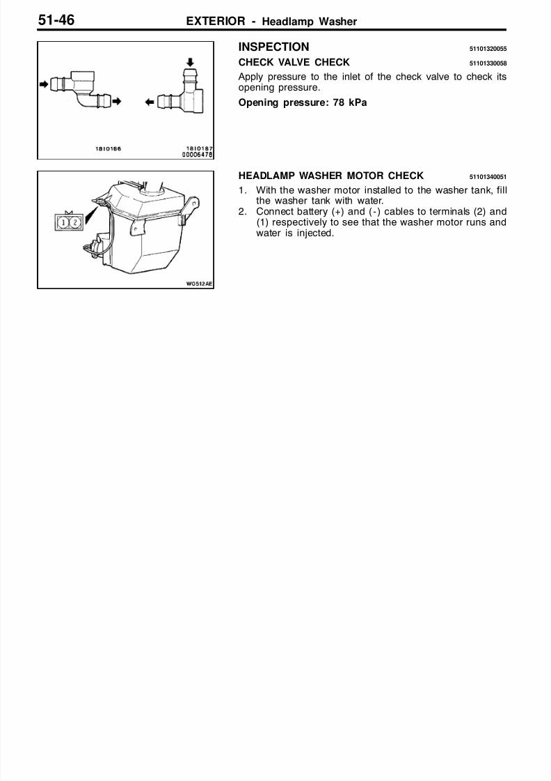
CHECK VALVE CHECK 51101330058
Apply pressure to the inlet of the check valve to check itsopening pressure.
Opening pressure: 78 kPa
HEADLAMP WASHER MOTOR CHECK 51101340051
1. With the washer motor installed to the washer tank, fillthe washer tank with water.
2. Connect battery (+) and ( - ) cables to terminals (2) and(1) respectively to see that the washer motor runs andwater is injected.

8/16/2019 51sPACE WAGON
http://slidepdf.com/reader/full/51space-wagon 47/54
EXTERIOR - Marks 51-47
MARKS 51101180110
<SPACE RUNNER>
REMOVAL AND INSTALLATION
1
2
2
1
"AA 1. “GDI” mark"AA 2. THREE DIAMOND and “SPACE
RUNNER” mark
INSTALLATION SERVICE POINT
"AA INSTALLATION OF MARKS
1. APPLICATION POSITION
Dimensions A, B, C and D (dimension from corner of mark
to notch on mark) are equal to dimensions A’, B’, C’ andD’ (dimension from installation reference point to corner of mark) respectively. Install the mark so that the dimensions
A, B, C and D are equal to the dimensions A’, B’, C’ andD’.
(1) “GDI” mark
Press line
Rear door end line
Press line
Quarter panel end line
<LH><RH>
A
A’
BC
D
B’C’
D’

8/16/2019 51sPACE WAGON
http://slidepdf.com/reader/full/51space-wagon 48/54
EXTERIOR - Marks51-48
Tailgate end line
Center line
Tailgate garnish line
12 mm
37 mm
(2) THREE DIAMOND and “SPACE RUNNER” mark
Press line
12 mm
33 mm
Press line
Tailgategarnish
(1) “GDI” mark
<SPACE WAGON>
REMOVAL AND INSTALLATION
1 2
1
"AA 1. “GDI” mark"AA 2. “MITSUBISHI” and “4 X 4” mark
8/16/2019 51sPACE WAGON
http://slidepdf.com/reader/full/51space-wagon 49/54
EXTERIOR - Marks 51-49
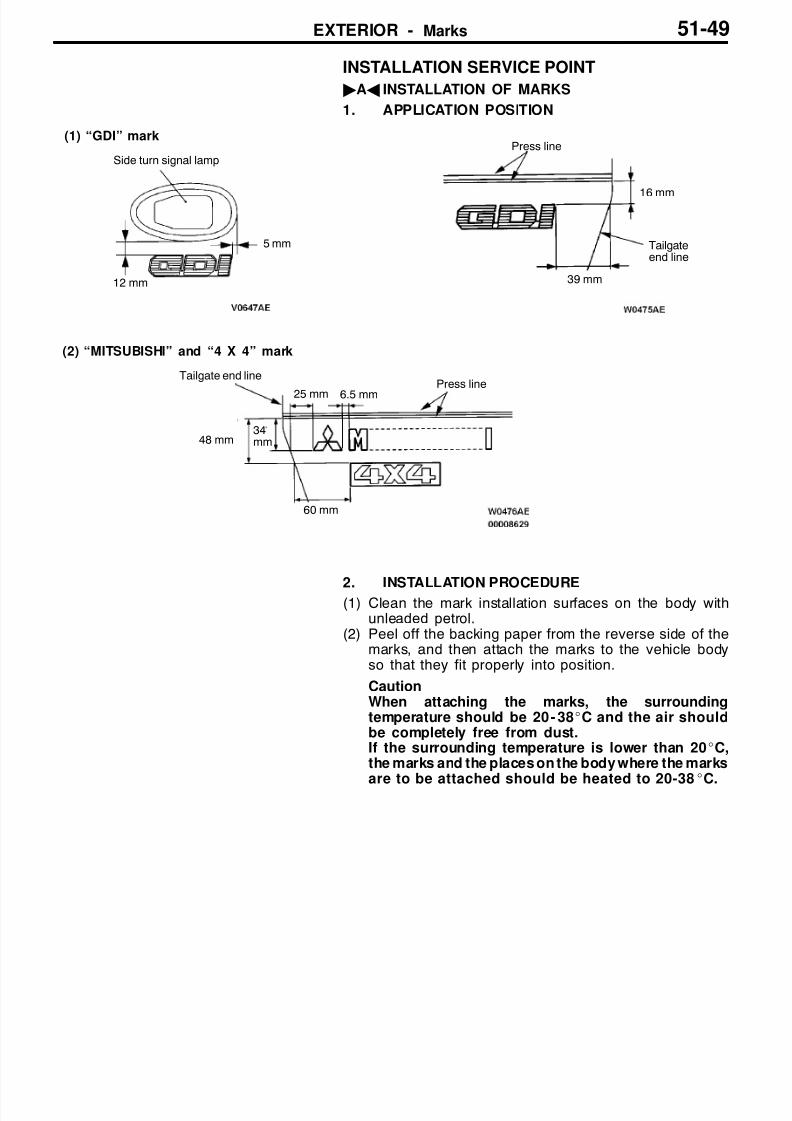
INSTALLATION SERVICE POINT
"AA INSTALLATION OF MARKS
1. APPLICATION POSITION
(1) “GDI” mark
Tailgateend line
34mm
12 mm
5 mm
6.5 mm
(2) “MITSUBISHI” and “4 X 4” mark
Side turn signal lamp
Press line
16 mm
39 mm
Press lineTailgate end line
48 mm
25 mm
60 mm
2. INSTALLATION PROCEDURE(1) Clean the mark installation surfaces on the body with
unleaded petrol.(2) Peel off the backing paper from the reverse side of the
marks, and then attach the marks to the vehicle bodyso that they fit properly into position.
CautionWhen attaching the marks, the surroundingtemperature should be 20 - 38_C and the air shouldbe completely free from dust.If the surrounding temperature is lower than 20_C,the marks and the places on the body where the marks
are to be attached should be heated to 20-38_C.

8/16/2019 51sPACE WAGON
http://slidepdf.com/reader/full/51space-wagon 50/54
EXTERIOR - Door Mirror51-50
DOOR MIRROR 51100640121
REMOVAL AND INSTALLATION
1
3
1
2
4
Section A - A
Instru-mentpanel
Section B - BView A
View A
Tabs
NOTE
: tab positions
4
5
A
A
B
B
1Mirror
Door mirror removal steps
1. Base cover2. Door mirror
AA" "AA 3. Mirror
Electronically remote-controlledmirror switch removal steps
4. Switch panel5. Electronically remote-controlled
mirror switch

8/16/2019 51sPACE WAGON
http://slidepdf.com/reader/full/51space-wagon 51/54
EXTERIOR - Door Mirror 51-51
REMOVAL SERVICE POINT
spot=RA AA" MIRROR REMOVAL
1. Using a hand, push the upper part of mirror to tilt it. Apply a protection tape as shown in the illustration. Inserta flat-tipped screwdriver between a notch behind the mirrorand the pivot plate, and then pry off the lower part of mirror from the pivot plate.
2. Pull the mirror toward you to remove it from the pivotplate.
INSTALLATION SERVICE POINT
"AA MIRROR INSTALLATION
1. Push the mirror to engage its upper part with the pivotplate.
Section A - A
Flat-tippedscrewdriver Mirror
Pivot plate
Protectiontape
Notches
A
A
AA
Section B - B
Pivot plate
Mirror
B B
B B
Section B - B
Pivot plate
Mirror
B B
BB

8/16/2019 51sPACE WAGON
http://slidepdf.com/reader/full/51space-wagon 52/54
EXTERIOR - Door Mirror51-52
2. While holding the pivot plate with a flat-tipped screwdriver,push the mirror to engage the clips at its lower part withthe pivot plate.
INSPECTION 51100650100
ELECTRONICALLY REMOTE-CONTROLLED MIRRORCHECK
<Vehicles with door mirror heater>
Battery connection terminal Direction of operation
3 4 5
UP
DOWN
LEFT
RIGHT
<Vehicles without door mirror heater>
Battery connection terminal Direction of operation
1 2 3
UP
DOWN
LEFT
RIGHT
Section A - A
Flat-tippedscrewdriver
Mirror
Pivot plate
A
A
A
A
<Vehicles withoutdoor mirror heater>
<Vehicles with doormirror heater>

8/16/2019 51sPACE WAGON
http://slidepdf.com/reader/full/51space-wagon 53/54
EXTERIOR - Door Mirror 51-53
ELECTRONICALLY REMOTE-CONTROLLED MIRRORSWITCH CONTINUITY CHECK
Switch Switch Terminal No.position
Left mirror Right mirror 5 8
1 6 9 10 11 1 2 3 6 9
Adjustment switch UP
DOWN
LEFT
RIGHT
Illumination
DOOR MIRROR PRINTED HEATING WIRE CHECK
Check that there is continuity between the terminal No.1 andthe terminal No.2.

8/16/2019 51sPACE WAGON
http://slidepdf.com/reader/full/51space-wagon 54/54
NOTES