5.1 Design and Construction of Liner Systems · 5.1 Design and Construction of Liner Systems ......
10
r '_ CJ Workman, J., and Keeble, R., nDesign and Construction of Uner Systems," Chapter 5.11N: Christensen et al. (eds), Sanitary Landfilllna: Process, Technology and Environmental Impact, Academic Press, New York, pp. 301-309 (1989} 5.1 Design and Construction of Liner Systems J.P. WORKMAN•- and R.l. KEEBLE .. •Browning-Ferris Industries, P.O. Box 3151, Houston, Texas 77253, USA .. Browning-Ferris Overseas Inc., UK INTRODUCTION The liner system in a landfill is the main line of defence against external migration of leachate and methane gas. A performance standard criteria is a rational approach to developing a liner system. A performance standard describes the expected performance of a lining system and specific design criteria are developed on a site specific basis. The liner system must not only be designed properly, but must be constructed properly. Good specifications, proper equipment and an adequate quality control programme must be implemented. LINER SYSTEM DESIGN There are two types of design methods for the design of landfills in the USA: the design standard and the performance standard. Design standards specify design applica!?le to all structures as the number, types and thickness of liners. Design standards are easy to interpret and provide uniform designs for all landfill operatOl'S. The performance standard describes the expected performance of a landfill and the design is prepared to meet this criteria. The performance standard increases flexibility for the landfill designer because it allows site specific information to influence the design and can result- in substantial-savings in construction costs. 301
Transcript of 5.1 Design and Construction of Liner Systems · 5.1 Design and Construction of Liner Systems ......

r '_ CJ
Workman, J., and Keeble, R., nDesign and Construction of Uner Systems," Chapter 5.11N: Christensen et al. (eds), Sanitary
Landfilllna: Process, Technology and Environmental Impact, Academic Press, New York, pp. 301-309 (1989}
5.1 Design and Construction of Liner Systems
J.P. WORKMAN•- and R.l. KEEBLE ..
•Browning-Ferris Industries, P.O. Box 3151, Houston, Texas 77253, USA .. Browning-Ferris Overseas Inc., UK
INTRODUCTION
The liner system in a landfill is the main line of defence against external migration of leachate and methane gas. A performance standard criteria is a rational approach to developing a liner system. A performance standard describes the expected performance of a lining system and specific design criteria are developed on a site specific basis.
The liner system must not only be designed properly, but must be constructed properly. Good specifications, proper equipment and an adequate quality control programme must be implemented.
LINER SYSTEM DESIGN
There are two types of design methods for the design of landfills in the USA: the design standard and the performance standard. Design standards specify design applica!?le to all structures ~ucb as the number, types and thickness of liners. Design standards are easy to interpret and provide uniform designs for all landfill operatOl'S.
The performance standard describes the expected performance of a landfill and the design is prepared to meet this criteria. The performance standard increases flexibility for the landfill designer because it allows site specific information to influence the design and can result- in substantial-savings in construction costs.
301
302 Workman and Keeble
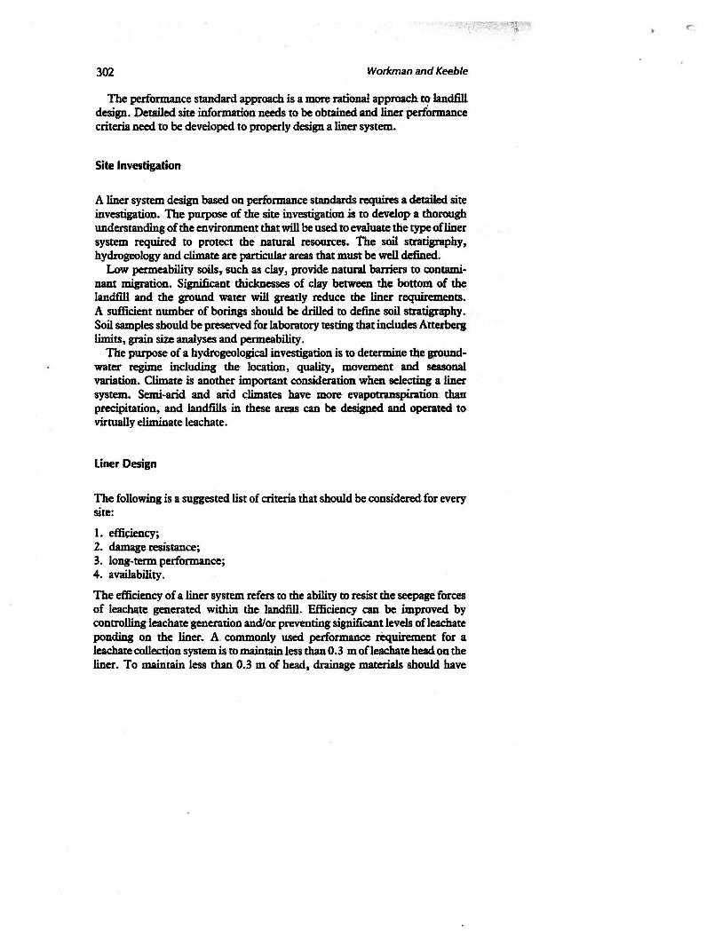
The performance standard approach is a more ratiOnal approaCh to landfill design. Detailed site information needs to be obtained and liner performance criteria need to be developed to properly design a liner system.
Site Investigation
A liner system design based on performance standards requires a detailed site investigation. The purpose of the site investigation is to develop a thorough understanding of the environment that will be used to evaluate· the type of liner system required to protect the natural resources. the soil stratigraphy, hydrogeology and climate are particular areas that must be well defined.
Low permeability soils, such as clay, provide natural barriers to contaminant migration. Significant thicknesses of clay between the bottom of the landfill and the ground water will greatly reduce the liner requirements. A sufficient number ofborings should be drilled to defJP.e soil stratigraphy. Soil samples should ·be preserved for laboratory testing that includes Atterberg limits, grain size analyses and permeability.
The purpose of a hydrogeological investigation is to determine the groundwater regime including the location, quality, movement and seasonal variation. Climate is another important consideration when selecting a liner system. Semi-arid and arid climates have more evapotranspiration. than precipitation, and landfills in these areas can be designed and operated to virtually eliminate leachate.
Liner Design
The following is a suggested list of criteria that should be considered for every site:
1. efficiency; 2. damage resistance; 3. long-term performance; 4. availability.
The efficiency of a liner system refers to the ability to resist the seepage forces of leachate generated within the landfill. Efficiency can be improved by controlling leachate ·generation and/or preventing significant levels of leachate ponding on the liner~ A. commonly used performance requirement for a leachate collection system is· to maintain less than 0.3 m ofleachate head on the liner. To maintain less than 0.3 m of head, drainage materials should have

Design and Construction of Uner Systems 303
permeabilities gfe&ter than 1 x 10⁻³ cmls and networks of properly spaced drainage pipe should be installed. Liner permeability, and slope of a landfill base are also considerations that affect' efficiency.
Damage is most likely to occur during construction and landfill operations. Synthetic liners-, which have excellent permeability properties, are easily damaged. Clay barriers have much better resistance to damage and have selfhealing properties.
Long-term performance of the liner system is of foremost importance. Criteria for determining the long-term performance are the permeability, leakage resistance and chemical resistance.
The permeability of the liner is often the most important factor in determining the long-term performance. Synthetic liner materials have very low permeabilities of 1 X 10-12 to 1 X 10-14 rnJs. A synthetic liner provides an effective low perm~bility b~er that will greatly enhance the efficiency of any liner system.
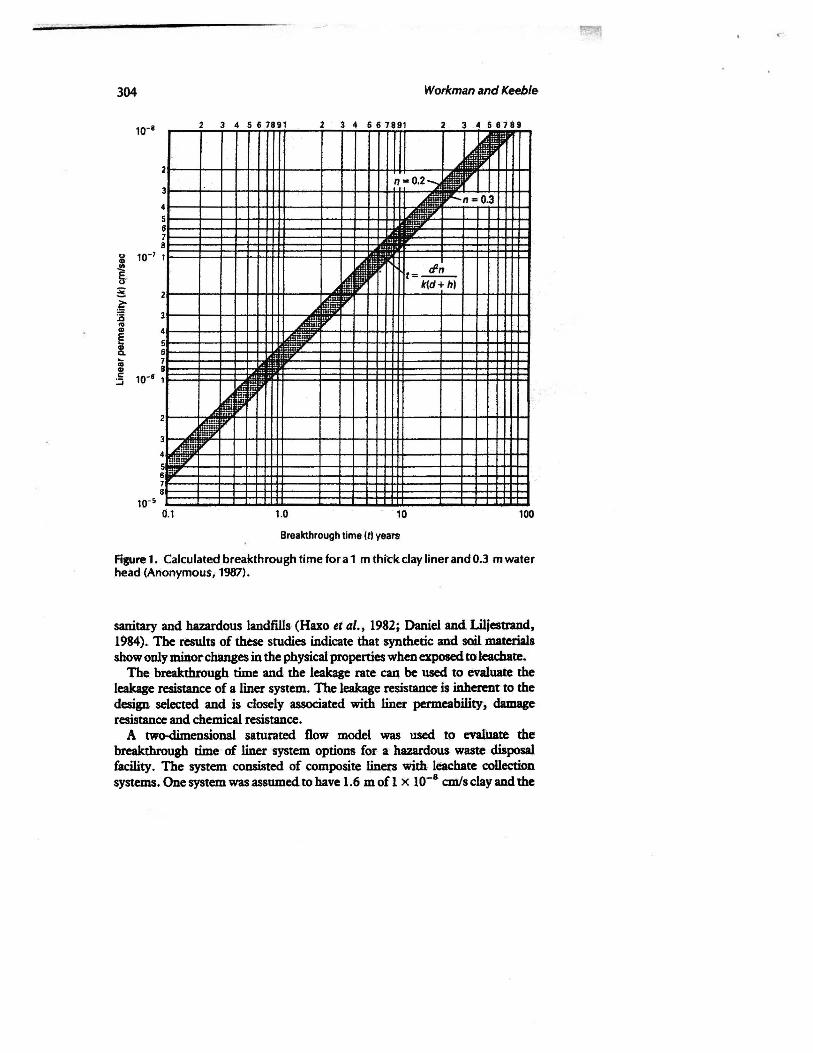
The permeability of soils will vary greatly. Typical conductivity of soils classified as clays by the Unified Soil Classification System. (Anonymous, 1987) will range from 10-7 to 10-11 rnls. The permeability will impact the breakthrough and leachate rate of a clay liner. Breakthrough time can be determined by the following equation:
where:
t = tfn k(d+ h)
t = breakthrough time in years d = liner thickness in metres h. = hydraulic head in metres k = permeability in m/year n = effective porosity.
(1)
Figure 1 presents the calculated breakthrough time for a 1 m thick clay liner and 0.3 m of head acting on the liner. The effective porosity was assumed to range from 0.2 to 0.3. As can be seen, permeabilities.should be low in order to contain contaminants. Clays· with permeabilities less than 10-9 rnls are commonly considered adequate to provide long-term protection of the environment.
The selection of synthetic liner materials should be based on the waste stream expected for the facility. Table 1 presents a summary of the effects of common chemical constituents on various synthetic liner materials prepared by Koerner (1982); see also Chapter 5.3, this volume.
The United States Environmental Protection Agency has sponsored some work to study the performance of synthetic and soil liners with leachate from
304 Workman and Keeble
4 5 6 7891 2 3 ; 7.: 11 3. 58789,...
2
Ill I= 0.3
: 10-7
g .. B
1
It dJn = k(d hi
~ :a 3 ... "' E
4
i ... ... ! ! 1o·• ::;
' 3
;r
~· 0.1 1.0 10 100
Breakthrough time 1t1 years
Figure 1. Calculated breakthrough time for a 1 m thick clay liner and 0.3 m water head (Anonymous, 1987).
sanitary and hazardous landfills (Haxo et al., 1982; Daniel and Liljestrand, 1984). The results of these studies indicate that synthetic and soil materials show only minor changes in the physical properties when exposed to leachate.
The breakthrough time and the leabge rate ~ be used to evaluate the leakage resistance of a liner system. The leakage resistance is inherent to the design selected and is closely associated with liner permeability, damage resistance and chemical resistance.
A two-dimensional saturated flow model was used tp evalUate the breakthrough time of liner system options for a hazardous waste disposal facility. The system consisted of composite liners with leachate collection systems. One system was.assumedto have 1.6 m ofl x 10-8 cmls clay and the

Table 1. Summary of the effect of chemical constituents on various synthetic liner materials (Koerner, 1982).
Chloro- Ethylene Chlorinated sulphonated propylene
poly- poly- Elasticized Epichloro- diene Poly- Polyvinyl Butyl ethylene ethylene poly- hydroin monomer chloroprene Poly- chloride
rubber (CPE) (CSPE) olefin rubber (EPCM) (neoprene) ethylene (PVC) Chemical 100°F 100•F 100°F 100°F 100"F 100°F 100°f 1WF 100"F
General: aliphatic X X X X X
hydrocarbons aromatic X X X X
hydrocarbons chlorinated solvents X X X X X X oxygenated solvents X X X X X X crude petroleum X X x X X
solvents alcohols X X X X X ~ ~ ~
Acids organic X X X X X X X X X inorganic X X X X X X X X X
Bases organic X X X X X X X X >.< inorganic X X X X X X X X X
Heavy metals X X X X X X X X X
Salts X X X X X X X X X
x = generally good resistance.
306 Workman and Keeble
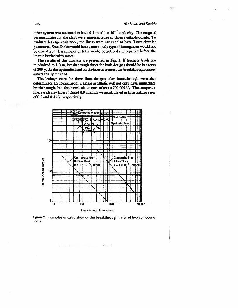
other system was assumed to have 0.9 m of 1 x 10⁻⁷ cm/s clay. The range of permeabilities for the clays were representative to tho.se available on site. To evaluate leakage resistance, the liners were assumed to have 3 mm circular punctures. Small holes would be the most likely type of damage that would not be discovered. Large, holes or tears wowd be noticed and ~before, the liner is buried with waste.
The results of this analysis are presented in Fig. 2. If leachate levels are minimized to 1.0 m, breakthrough times for both designs should be in excess of800 y. As the hydraulic head on the liner increases, the breakthrough time is substantially reduced.
The leakage rates for these linell designs after breakthrough were also determined. In comparison, a single synthetic will not only have immediate breakthrough, but also have leakage rates of about 700 000 J/y. The composite liners with clay layers I. 6 and 0.9 m thick were calculated to have leakage rates of0.2 and 0.4 Jly, respectively.
Saturated waste Soil buffer
I I
II"T " Synthetic liner
r-,flay <" ' IT " 100
'" ~-' /Co mposite liner r' Composite liner
0.9 3m Thick 1.6mThic~ ., k= t x to -7 Cm/Sec k = 1 X 10- 7Cm/Sec
1\..
L'\c
' ' ... , '\ 1\
' 1 ~.
10 100 1000 10,000
Breakthrough time, years
Figure 2. Examples of calculation of the breakthrough times of two composite liners.

Design and Construction of Liner Systems 307
The availability of materiills will impact the liner design and the· planned performance. Soil betonite ~' asphalt and soil cement are a few examples of fabricated materials· that have been used for low permeability barriers.
Commonly Used Designs
Figure 3 shows several liner systems commonly used by the waste disposal industry in the USA. Figure 3a presents a single clay liner. This liner design is normally used where a substantial th.tckness of natural low permeability soil
0.6toTicompacted lowl 3.0 m ...I_ permeability soil
(a) Compacted clay
Synthetic liner
iT _L .
0.5 to Compacted low 1.0 m .J._ permeabilitysoi
(b) Composite liner
Leak detection zone Synthetic line.~~ ;
0.5 toT ~mpacted lj 1.0 m...!.. permeability soil
(c) Double liner (d) Single synthetic
Synthetic liners
Leak detction zone
lei Double composite
Figure 3. Examples of different liner systems used in the USA.

303 Workman and Keeble
is located beneath the landfill. The purpose of the liner is, to provide a homogeneous engineered. ~er in addition to the natural soil. This liner system is resistant to damage with~ut total failure of the liner system.
The examples presented in, Fig. 3c,.d· rely principally on the synthetic liners as a hydraulic . barrier. These designs are commonly used where low petmeability soils are not available. However, synthetic liners are easily damaged and subject to significant leakage. A double liner with a leak detection/collection systeq~ (Fig; 3c) is normally preferred by the industry because· of the ability to collect leachate that may penetrate the primary liner .
. Composite and double composite designs (Fig. 3b, e) are. suggested when vulnerable site conditions exist. The composite liner system provides long breakthrough time, low leakage rates, and can withstand substantial damage without total failure of the liner system. These liners are. costly and time consuming to build, particularly if low permeability soils are not available on site.
CONSTRUCTION OF LINERS
Synthetic liners must be free of holes, rips and punctures; seams must be welded to obtain strong; leak-resistant joints. Proper equipment and construction procedures are required to build a low permeability soil liner. The object of construction is to obtain a uniform soil material absent of discontinuities such as PQOrly bonded lifts, void~ and poorly compacted zones.
The soil moisture/density relationship is critical to proper liner construction. The compaction moisture content should always be wet of the optimum compaction moisture content and the plastic limit of the soil. The optimum mojsture and the plastic limit are usually close, but rarely the same. As the soil moisture content decreases, more. compaction effort will be required to eliminate discontinuities. Soils will become brittle and non-plastic when the moisture content is below the plastic limit, and discontinuities may be impossible to eliminate.
The compacted thickness of each.lift should be less than the length of the compactor's tamping feet. The purpose of limiting the lift thickness is to enable the tamping feet to fully penetrate the soil lift and bond successi'Ve lifts together.
A sufficient number of passes should be applied to each lift to eliminate discontinuities in the soil liner. Frequently density can be achieved without obtaining a uniform and homogeneous soil liner. The required number of passes should be verified before construction based on experimentation with the equipment and soil conditions.

Design and Construction of Uner Systems 309
CONCLUSIONS
The long-tenn performance of a liner system is critical to the protection of the environment. Both proper design and construction are required to achieve the desired long-term performance. A rational approach to liner design is the performance standard method. This method requires a detailed site investigation and a defined set of penormance criteria. The purpose of the site investigation is to develop a thorough understanding of the environment and determine the vulnerability of the natural ground-water resources. Performance criteria should include liner efficiency, damage resistance, long-term performance, and material availability.
A low permeability soil liner is an important component of a liner system. Low permeability soil liners can be constructed. Proper construction equipment and procedures must be used to minimize the discontinuities in the soil that can cause seepage.
REFERENCES
Anonymous (1987). 'American Society for Testing and Materials', Annual Book of ASTM Standards, Section 4, Vol. 04.08, Soil and Rock; Building Stones.
Daniel, D.E. and Liljestrand, H.M. (1984). 'Effects of Landfill Leachate on Natural Liner Systems', Geotechnical Engineering Report GR83-6, Geotechnical Engineering Department, the University of Texas, Austin, Texas.
Haxo, H.E., White, R.M., Haxo, P.D. and Fong, M.A. (1982). 'Liner Materials Exposed to Municipal Solid Waste Leac~te', EPA-600/2-82/097 (NTIS No .. PB 83-147-801). US Environmental Protection Agency, Cincinnati, Ohio.
Koerner, R.M. (1982). 'Designing:with Geosynthetics'. Prentice Hall, N.J.