5. Gas Turbine Cycles - Engsoft Cycle Power Plants 5. Gas Turbine Cycles 3 /64 HIoPE Simple Cycle...
64
Combined Cycle Power Plants 5. Gas Turbine Cycles 1 /64 HIoPE 5. Gas Turbine Cycles
-
Upload
vuongkhuong -
Category
Documents
-
view
237 -
download
1
Transcript of 5. Gas Turbine Cycles - Engsoft Cycle Power Plants 5. Gas Turbine Cycles 3 /64 HIoPE Simple Cycle...

Combined Cycle Power Plants 5. Gas Turbine Cycles 1 /64
HIoPE
5. Gas Turbine Cycles
Combined Cycle Power Plants 5. Gas Turbine Cycles 2 /64
HIoPE
Regenerative Cycle 21 2
Combined Cycle 52 5
Closed Cycle 61 6
Simple Cycle 2 1
Intercooled Cycle 43 4
Reheat Cycle 36 3
Combined Cycle Power Plants 5. Gas Turbine Cycles 3 /64
HIoPE
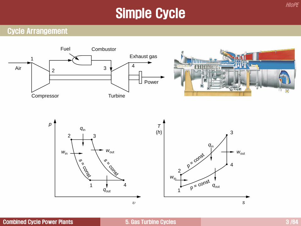
Simple Cycle
Cycle Arrangement
Compressor
Fuel Combustor
Turbine
Air
Power
Exhaust gas 1
2 4 3
p
2
1
T
(h)
s
qin
3
4 1
2
3
4
qout
win wout
win
wout
qin
qout
Combined Cycle Power Plants 5. Gas Turbine Cycles 4 /64
HIoPE
Simple Cycle
The term simple cycle is used to distinguish this configuration from the complex cycles, which utilizes
additional components, such as heat exchanger for regeneration, intercooler, reheating system, or steam
boilers.
This cycle is suitable for a fixed speed and fixed load operation, such as power generation.
In order to analyze gas turbine system in a convenient form, the assumptions listed below are frequently
used.
1) The working fluid is treated as the air. The air is an ideal gas and has a constant specific heat. (In
practice, there is a change in the composition of the working fluid because of the combustion process)
2) The combustion process is replaced by a heat transfer process from an external source. In other words,
the mass flow rate remains constant throughout the system.
3) The inlet and exhaust processes are replaced by a constant pressure process that will in turn complete
the gas turbine cycle.
4) All processes are internally reversible.
The combination of these assumption is called the air-standard cycle approach.
General Notes
Combined Cycle Power Plants 5. Gas Turbine Cycles 5 /64
HIoPE
Simple Cycle Analysis [1/13]
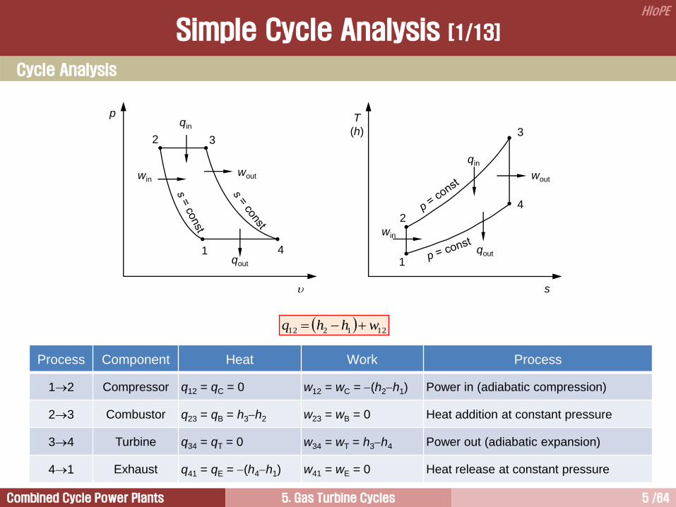
Process Component Heat Work Process
12 Compressor q12 = qC = 0 w12 = wC = (h2h1) Power in (adiabatic compression)
23 Combustor q23 = qB = h3h2 w23 = wB = 0 Heat addition at constant pressure
34 Turbine q34 = qT = 0 w34 = wT = h3h4 Power out (adiabatic expansion)
41 Exhaust q41 = qE = (h4h1) w41 = wE = 0 Heat release at constant pressure
121212 whhq
Cycle Analysis
p
2
1
T
(h)
s
qin
3
4 1
2
3
4
qout
win wout
win
wout
qin
qout

Combined Cycle Power Plants 5. Gas Turbine Cycles 6 /64
HIoPE
0 5 10 15 20Pressure Ratio [r]
0.0
0.1
0.2
0.3
0.4
0.5
0.6
0.7
0.8
Th
erm
alE
ffic
ien
cy
Thermal efficiency in a simple cycle gas
turbine increases with pressure ratio
and specific heat ratio.
The increasing rate of the thermal
efficiency is getting smaller as the
pressure ratio increases.
4
3
1
2
p
p
p
pr
crth
111
/1
1
rc
2
1
23
14
23
1423
23
4123
23
3412 11T
T
TT
TT
hh
hhhh
q
q
ww
q
w
inputheat
ouputworknet
in
sys
th
Thermal Efficiency
Simple Cycle Analysis [2/13]

Combined Cycle Power Plants 5. Gas Turbine Cycles 7 /64
HIoPE
1
3
T
Tt
Specific work output:
124341342312 TTcTTcwwwww ppsys
1
111
11 /1
/1
1
c
ctr
rt
Tc
w
p
sys
The specific work output, which is the output per unit mass flow rate of working fluid, is a function of
pressure ratio and maximum cycle temperature.
The specific work output increases with the pressure ratio when the maximum cycle temperature is greater
than a certain value.
There is a pressure ratio having a maximum specific work out in a constant t-curve.
Specific Work Output
4
3
1
2
p
p
p
pr
1
rc
Simple Cycle Analysis [3/13]
0 5 10 15 20Pressure Ratio [r]
0.0
0.5
1.0
1.5
2.0
Sp
ecific
Wo
rkO
utp
ut[w
/CT
]sys
1p
t = 2
t = 3
t = 4
t = 5

Combined Cycle Power Plants 5. Gas Turbine Cycles 8 /64
HIoPE
Optimum Pressure Ratio for a Given TIT [1/3]
There are different optimum pressure ratios in
terms of thermal efficiency and specific work
output for a given maximum cycle temperature.
The thermal efficiency increases with the
pressure ratio, and it has a maximum value
when the air temperature at the compressor
outlet is equal to TIT.
In this limiting case, the cycle net work tends
toward zero, and the thermal efficiency
approaches the Carnot efficiency. In terms of
available work output (= turbine work –
compressor work), it increases with pressure
ratio and reaches a maximum at a certain
pressure ratio, then it becomes smaller, and
finally reaches zero when the air temperature at
the compressor outlet is equal to TIT.
Therefore, it is clear that there are different optimum pressure ratios in terms of thermal efficiency and
specific work output for a given maximum cycle temperature.
This means that the maximum net specific work and the maximum thermal efficiency do not occur at the
same pressure ratio. Therefore, in designing gas turbines, the design pressure ratio must be a compromise
between the maximum thermal efficiency and the maximum specific work.
Simple Cycle Analysis [4/13]
T
(h)
s
1
2
3
4
4
3
2
2
4
3
Tmax
Combined Cycle Power Plants 5. Gas Turbine Cycles 9 /64
HIoPE
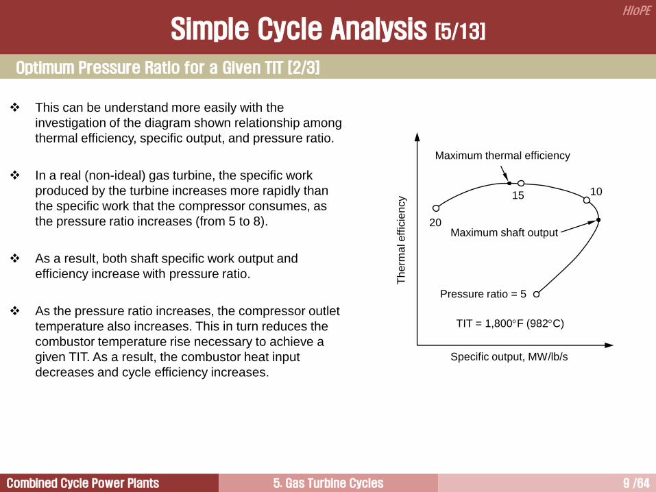
This can be understand more easily with the
investigation of the diagram shown relationship among
thermal efficiency, specific output, and pressure ratio.
In a real (non-ideal) gas turbine, the specific work
produced by the turbine increases more rapidly than
the specific work that the compressor consumes, as
the pressure ratio increases (from 5 to 8).
As a result, both shaft specific work output and
efficiency increase with pressure ratio.
As the pressure ratio increases, the compressor outlet
temperature also increases. This in turn reduces the
combustor temperature rise necessary to achieve a
given TIT. As a result, the combustor heat input
decreases and cycle efficiency increases.
Optimum Pressure Ratio for a Given TIT [2/3]
Simple Cycle Analysis [5/13]
Specific output, MW/lb/s
Th
erm
al e
ffic
ien
cy
Maximum thermal efficiency
Maximum shaft output
Pressure ratio = 5
10 15
20
TIT = 1,800F (982C)
Combined Cycle Power Plants 5. Gas Turbine Cycles 10 /64
HIoPE
At the point corresponding to the maximum shaft specific work output (turbine specific work produced
minus compressor specific work consumed), the turbine specific work produced and the compressor
specific work consumed increase at the same rate.
As pressure ratio increases further (beyond the maximum shaft output), the compressor specific work
consumed increases as a greater rate than the turbine specific work produced and, as a result, the shaft
work output actually decreases.
However, because the combustor heat input continues to decrease, the efficiency continue to increase as
pressure increases (from 8 to 16). The reason for this is that the shaft specific work output decreases
because compressor specific work consumed is increasing faster than turbine specific work output, as the
pressure ratio increases. Therefore, shaft specific work output decreases.
However, fuel consumption is reduced and overall thermal efficiency increases because of higher
compressor outlet temperatures due to higher pressure ratios.
As the pressure ratio increases further (greater than 16), the increase in compressor specific work
consumed offsets the advantage of higher compressor outlet temperature and overall efficiency begins to
decrease.
The actual pressure ratio at which this occurs depend on the specific gas turbine considered.
Optimum Pressure Ratio for a Given TIT [3/3]
Simple Cycle Analysis [6/13]
Combined Cycle Power Plants 5. Gas Turbine Cycles 11 /64
HIoPE
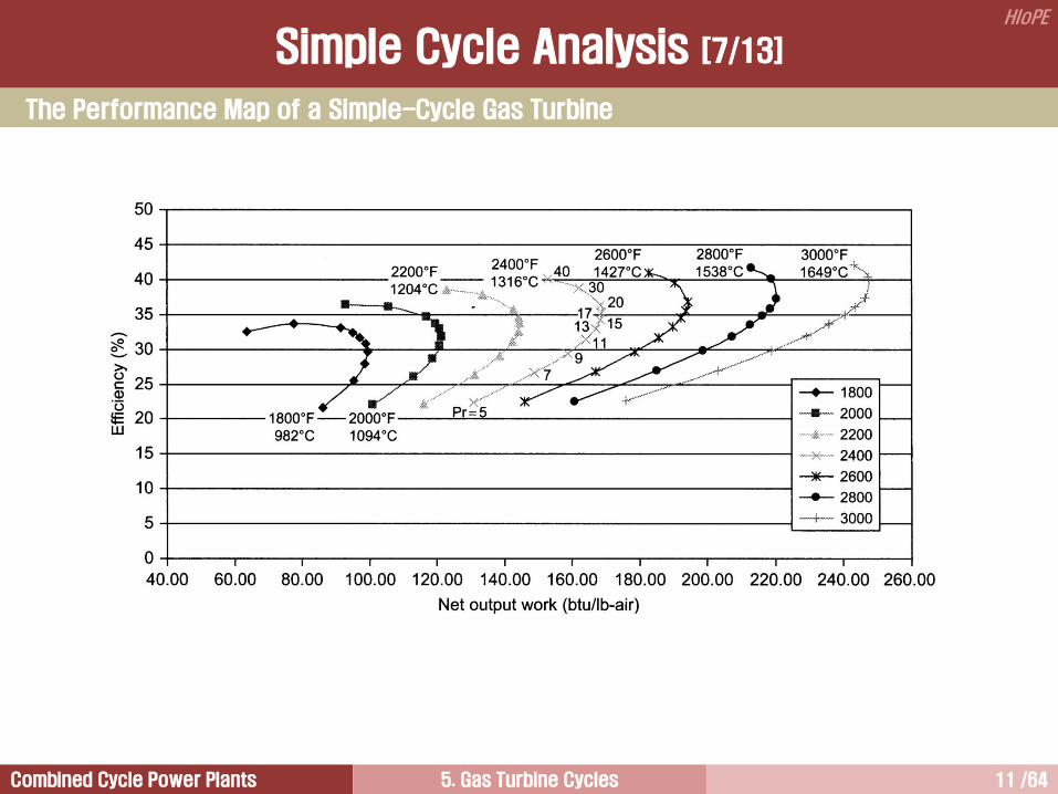
The Performance Map of a Simple-Cycle Gas Turbine
Simple Cycle Analysis [7/13]

Combined Cycle Power Plants 5. Gas Turbine Cycles 12 /64
HIoPE
h1 = enthalpy at compressor inlet
h2s = enthalpy at constant entropy and
compressor discharge pressure
h2 = actual enthalpy at compressor discharge
pressure
h3 = enthalpy at turbine inlet
h4s = enthalpy at constant entropy and turbine
exit pressure
h4 = actual enthalpy at turbine exit pressure
p
2
1
T
(h)
s
Qin
3
4 1
2s
3
4
Qout
Win
Wout
2
4s
12
12
hh
hh sC
s
Thh
hh
43
43
Practical Brayton Cycle
Simple Cycle Analysis [8/13]
Combined Cycle Power Plants 5. Gas Turbine Cycles 13 /64
HIoPE
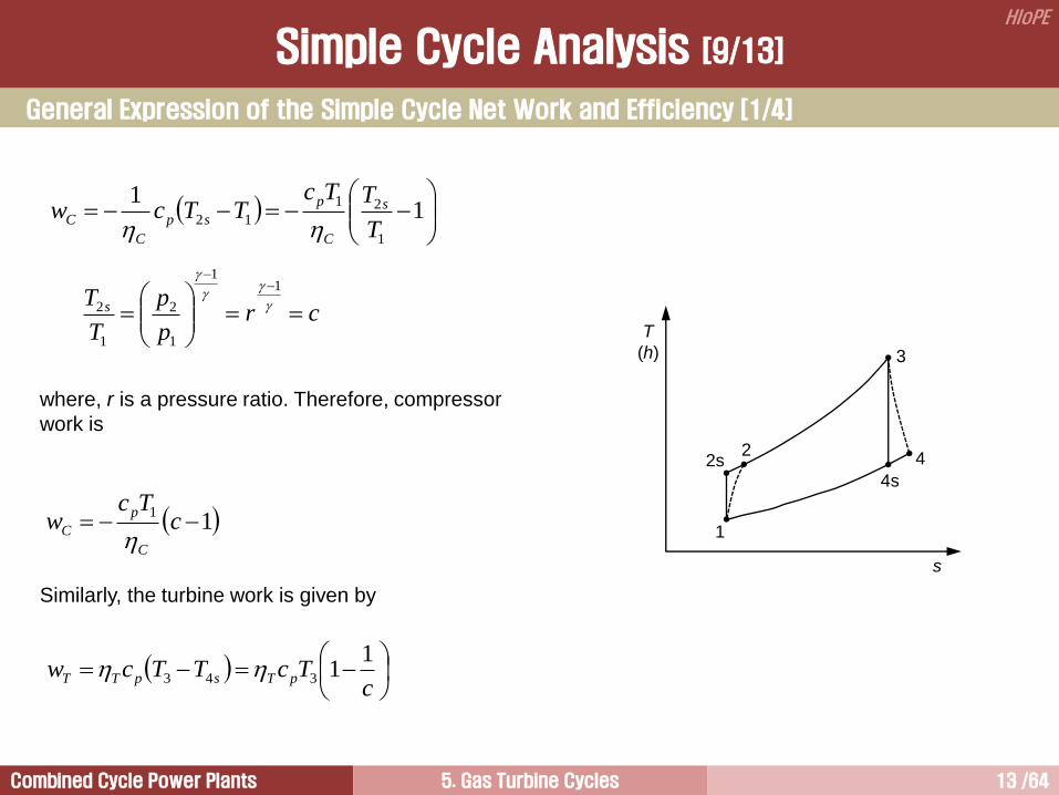
General Expression of the Simple Cycle Net Work and Efficiency [1/4]
1
1
1
21
12T
TTcTTcw s
C
p
sp
C
C
crp
p
T
T s
1
1
1
2
1
2
where, r is a pressure ratio. Therefore, compressor
work is
11 c
Tcw
C
p
C
Similarly, the turbine work is given by
cTcTTcw pTspTT
11343
Simple Cycle Analysis [9/13]
T
(h)
s
1
2s
3
4
4s
2
Combined Cycle Power Plants 5. Gas Turbine Cycles 14 /64
HIoPE
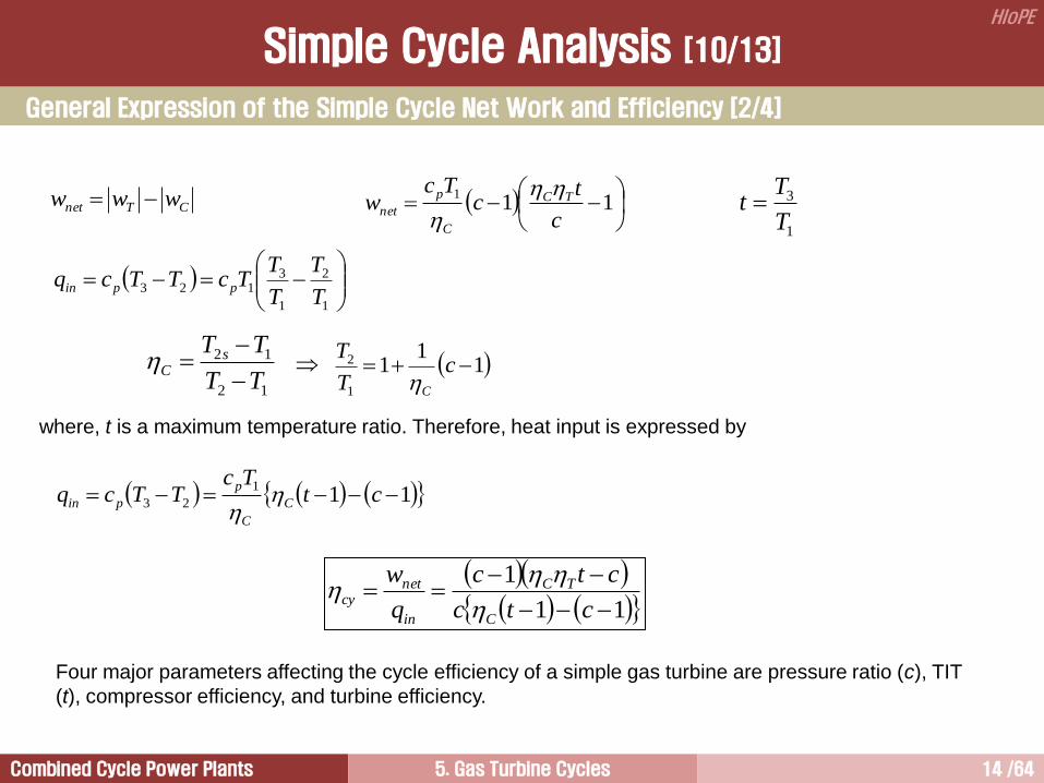
General Expression of the Simple Cycle Net Work and Efficiency [2/4]
CTnet www
11
1
c
tc
Tcw TC
C
p
net
1
2
1
3123
T
T
T
TTcTTcq ppin
12
12
TT
TT sC
1
11
1
2 cT
T
C
where, t is a maximum temperature ratio. Therefore, heat input is expressed by
111
23 ctTc
TTcq C
C
p
pin
11
1
ctc
ctc
q
w
C
TC
in
netcy
Four major parameters affecting the cycle efficiency of a simple gas turbine are pressure ratio (c), TIT
(t), compressor efficiency, and turbine efficiency.
1
3
T
Tt
Simple Cycle Analysis [10/13]
Combined Cycle Power Plants 5. Gas Turbine Cycles 15 /64
HIoPE
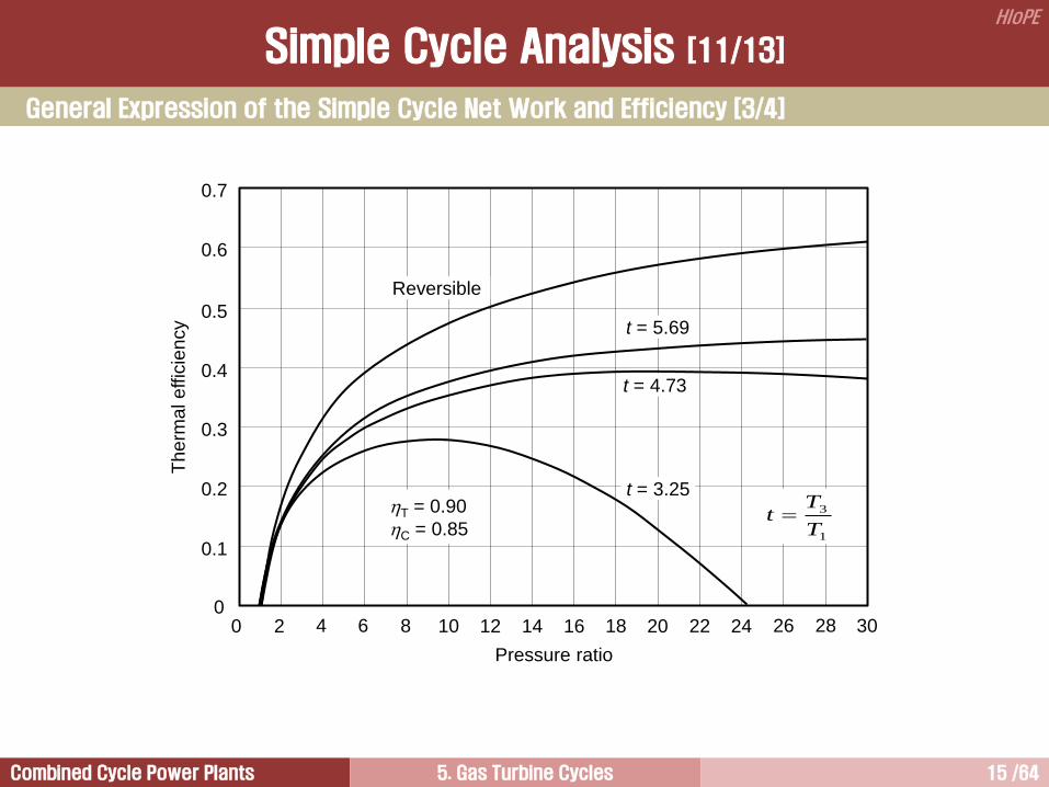
Pressure ratio
t = 3.25
t = 4.73
t = 5.69
Reversible
0.7
0.1
Therm
al effic
iency
2 4 6 8 0 10 12 14 16 18 20 22 24 26 28 30
0.6
0.5
0.4
0.3
0.2
0
1
3
T
Tt T = 0.90
C = 0.85
General Expression of the Simple Cycle Net Work and Efficiency [3/4]
Simple Cycle Analysis [11/13]
Combined Cycle Power Plants 5. Gas Turbine Cycles 16 /64
HIoPE
In general, the cycle efficiency is relatively low, because of the high EGT, and because a significant portion
of the turbine output is used for compressor operation.
For a given turbine and compressor efficiency, the cycle performance is determined by the TIT and pressure
ratio.
The TIT is usually fixed by the metallurgical temperature limit of the first row of turbine blade.
As the TIT increases, the cycle efficiency is greatly improved.
The impact of the pressure ratio on the cycle efficiency is quite different.
There is an optimum pressure ratio that produces the maximum cycle efficiency.
The optimum pressure ratio increases with the TIT.
General Expression of the Simple Cycle Net Work and Efficiency [4/4]
Simple Cycle Analysis [12/13]

Combined Cycle Power Plants 5. Gas Turbine Cycles 17 /64
HIoPE
Shaft power application
Simple Cycle Efficiency
Simple Cycle Analysis [13/13]

Combined Cycle Power Plants 5. Gas Turbine Cycles 18 /64
HIoPE
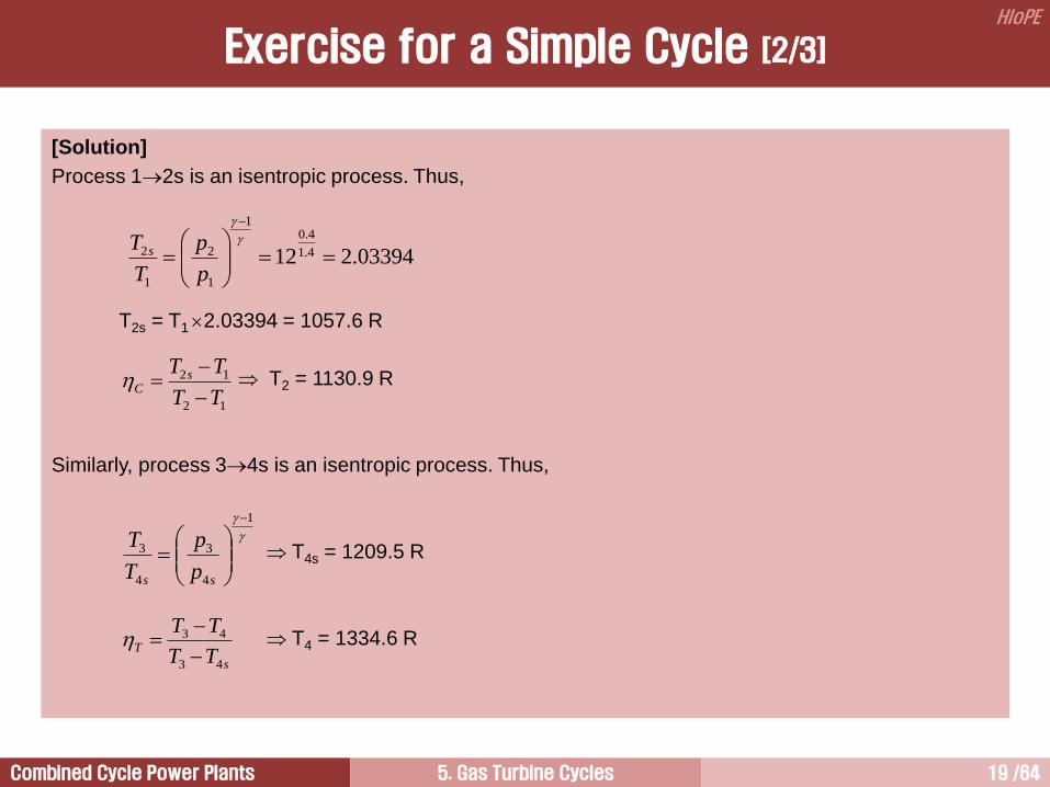
[Exercise 7.1]
Calculate the cycle efficiency and net work per pound of air. A gas turbine is operated under the
following conditions.
• Compressor inlet pressure and temperature 14.7 psia, 60F
• Pressure ratio 12
• Compressor efficiency 0.88
• Turbine inlet temperature 2000F
• Turbine efficiency 0.90
• Average constant pressure specific heat 0.25 Btu/lb-R
• Specific heat ratio 1.4
The pressure drops in the combustor, compressor inlet, and turbine outlet are assumed to be negligible.
Exercise for a Simple Cycle [1/3]
T
(h)
s
1
2s
3
4
4s
2
Combined Cycle Power Plants 5. Gas Turbine Cycles 19 /64
HIoPE
[Solution]
Process 12s is an isentropic process. Thus,
T2s = T1 2.03394 = 1057.6 R
T2 = 1130.9 R
Similarly, process 34s is an isentropic process. Thus,
T4s = 1209.5 R
T4 = 1334.6 R
03394.212 4.1
4.01
1
2
1
2
p
p
T
T s
12
12
TT
TT sC
1
4
3
4
3
ss p
p
T
T
s
TTT
TT
43
43
Exercise for a Simple Cycle [2/3]

Combined Cycle Power Plants 5. Gas Turbine Cycles 20 /64
HIoPE
[Solution]
Heat input in the combustor is
Compressor work and turbine work are
Cycle efficiency is
cy = 0.387 or 38.7%
Cycle network is
128.6 Btu/lb
23 TTcq pin
12 TTcw pC
43 TTcw pT
23
141TT
TT
q
ww
in
CTcy
CTnet www
11
1
ctc
ctc
q
w
C
TC
in
netcy
Exercise for a Simple Cycle [3/3]

Combined Cycle Power Plants 5. Gas Turbine Cycles 21 /64
HIoPE
Regenerative Cycle 2
Combined Cycle 5
Simple Cycle 1
Intercooled Cycle 4
Reheat Cycle 3
Closed Cycle 6
Combined Cycle Power Plants 5. Gas Turbine Cycles 22 /64
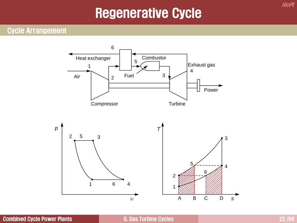
HIoPE
Regenerative Cycle
Cycle Arrangement
Compressor
Fuel
Combustor
Turbine
Air
Power
Exhaust gas
Heat exchanger
1
2
5
3 4
6
p
2
1
T
s
3
4 1
2
3
4 6
5
5
6
A B C D
Combined Cycle Power Plants 5. Gas Turbine Cycles 23 /64
HIoPE
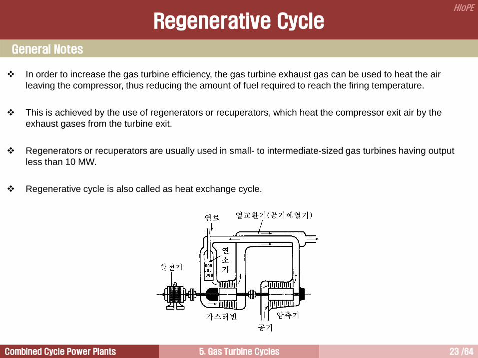
In order to increase the gas turbine efficiency, the gas turbine exhaust gas can be used to heat the air
leaving the compressor, thus reducing the amount of fuel required to reach the firing temperature.
This is achieved by the use of regenerators or recuperators, which heat the compressor exit air by the
exhaust gases from the turbine exit.
Regenerators or recuperators are usually used in small- to intermediate-sized gas turbines having output
less than 10 MW.
Regenerative cycle is also called as heat exchange cycle.
General Notes
Regenerative Cycle

Combined Cycle Power Plants 5. Gas Turbine Cycles 24 /64
HIoPE
A Typical Regenerative Cycle Gas Turbine
Air flow path – Mercury 50 gas turbine (Solar)
Power = 4.6 MW
PR = 9.9:1
TIT = 2200F (1204C)
th = 38.5%
Regenerative Cycle

Combined Cycle Power Plants 5. Gas Turbine Cycles 25 /64
HIoPE
Process Component Heat Work Process
12 Compressor q12 = qC = 0 w12 = wC = (h2h1) Power in (adiabatic compression)
25 Heat Ex. q52 = qin = h5h2 w52 = wHE = 0 Heat addition through heat exchanger
53 Combustor q53 = qB = h5h3 w53 = wB = 0 Heat addition in a burner
34 Turbine q34 = qT = 0 w34 = wT = h3h4 Power out (adiabatic expansion)
46 Heat Ex. q46 = qout = (h6h4) w46 = wHE = 0 Heat transfer to compressor discharged air
(h4h6 = h5h2)
61 Exhaust q61 = qE = (h6h1) w61 = wE = 0 Heat release to atmosphere
121212 whhq
Cycle Analysis
Regenerative Cycle Analysis [1/6]
p
2
1
T
s
3
4 1
2
3
4 6
5
5
6
A B C D
Combined Cycle Power Plants 5. Gas Turbine Cycles 26 /64
HIoPE
압력비 vs 비출력
0 5 10 15 20Pressure Ratio [r]
0.0
0.5
1.0
1.5
2.0S
pecific
Wo
rkO
utp
ut[w
/CT
]sys
1p
t = 2
t = 3
t = 4
t = 5
The regenerative cycle has
the exactly same specific
work out with a simple cycle.
11
11
c
ct
Tc
w
p
sys
1
3
T
Tt
1
rc
1
2
p
pr
Regenerative Cycle Analysis [2/6]

Combined Cycle Power Plants 5. Gas Turbine Cycles 27 /64
HIoPE
압력비 vs 열효율
0 5 10 15 20Pressure Ratio [r]
0
0.1
0.2
0.3
0.4
0.5
0.6
0.7
0.8
0.9
Th
erm
alE
ffic
ien
cy
Simple cycle efficiency
t = 2
t = 3
t = 4
t = 5t = 6
t
cth 1
1
3
T
Tt
1
rc1
2
p
pr
4
1
3
2 11T
T
T
Tth
t
cth 1
사이클 최고온도가 일정한 상태에서
압력비가 작아질수록 재생사이클 가스터빈 열효율 향상.
압력비가 일정한 상태에서 최고온도가 증가할수록 열효율이 향상된다.
4
1
3
2 11T
T
T
Tth
재생사이클 가스터빈은 TIT가 증가할수록, 그리고 EGT가 증가할수록 열효율 향상.
Regenerative Cycle Analysis [3/6]

Combined Cycle Power Plants 5. Gas Turbine Cycles 28 /64
HIoPE
The cycle efficiency decreases as the pressure ratio increases, which is opposite to that of a simple cycle.
This is due to the fact that, as the pressure ratio increases the air temperature exiting the compressor
increases and ultimately will exceed that of the turbine exhaust gas temperature. Then heat in the heat
exchanger (regenerator) will be lost from the air to the exhaust gases instead of desired gain.
The efficiency with lower TITs, say at t=2, is seen to become negative soon after the pressure ratio 11.3 is
exceeded. The reason is that the temperature at compressor outlet actually exceeds the assumed
combustion temperature in this case.
In many cases, regeneration is not desirable. This is because the efficiency increases with pressure ratio, if
regenerative cycle is not employed.
Efficiency, with regenerative cycle rises very rapidly with increase in maximum temperature of the cycle.
Lower pressure ratios and high cycle temperatures are favorable for the regenerative cycle, since a large
heat recovery is then possible.
After the efficiency becomes equal to that of simple cycle, any further increase of pressure ratio will yield an
efficiency which is lower than that of simple cycle and that is of no interest.
Power output may be reduced by 10% for a given size of plant because of the pressure losses occurred in
the heat exchanger.
Normally, micro gas turbines having lower thermal efficiency adopts this kind of arrangement to improve
thermal efficiency.
Regenerative Cycle Analysis [4/6]

Combined Cycle Power Plants 5. Gas Turbine Cycles 29 /64
HIoPE
24
25
24
25
TT
TT
hh
hhreg
53
1243
TT
TTTT
q
ww
in
CTcy
2423
1243
TTTT
TTTT
reg
cy
1
2
1
3
3
4
1
2
1
3
1
2
1
3
3
4
1
3 1
T
T
T
T
T
T
T
T
T
T
T
T
T
T
T
T
T
T
reg
cy
11
1
2
C
c
T
T
cT
TT
111
3
4
It can be seen that the irreversibility of the system significantly lower the cycle efficiency.
Compared with the simple gas turbine system, the optimum pressure ratio is smaller for the regenerative
cycle.
The small pressure ratio means a small cycle net output.
Therefore, the cost associated with this output reduction must be weighted against the saving that can be
affected by the cycle efficiency improvement.
Cycle Efficiency of Practical Regenerative Cycles
Regenerative Cycle Analysis [5/6]
Pressure ratio
t = 4.73
t = 5.69
Reversible 0.7
0.1
Therm
al e
ffic
iency
2 4 6 8 0 10 12 14 16 18 20 22 24 26 28 30
0.6
0.5
0.4
0.3
0.2
0
1
3
T
Tt
T = 0.90
C = 0.85
reg = 0.80
0.8
0.9
1.0
Practical t = 5.69
t = 4.73
Combined Cycle Power Plants 5. Gas Turbine Cycles 30 /64
HIoPE
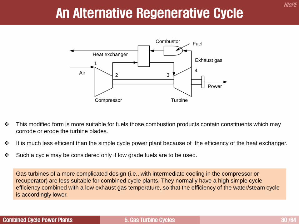
An Alternative Regenerative Cycle
This modified form is more suitable for fuels those combustion products contain constituents which may
corrode or erode the turbine blades.
It is much less efficient than the simple cycle power plant because of the efficiency of the heat exchanger.
Such a cycle may be considered only if low grade fuels are to be used.
Gas turbines of a more complicated design (i.e., with intermediate cooling in the compressor or
recuperator) are less suitable for combined cycle plants. They normally have a high simple cycle
efficiency combined with a low exhaust gas temperature, so that the efficiency of the water/steam cycle
is accordingly lower.
Compressor
Fuel Combustor
Turbine
Air
Power
Exhaust gas Heat exchanger
1
2 3 4
Combined Cycle Power Plants 5. Gas Turbine Cycles 31 /64
HIoPE
1 초소형 발전 정의: Micro Gas Turbine (and/or Fuel Cell)을 이용한 전력생산
기술적 특성:
구(old) 기술 (시장출현 후 거의 1세기 경과 과거 가격 경쟁력 열위)
초소형 발전시스템은 현재 기존설비(디젤발전기)에 대한 가격경쟁력 확보
2 초소형 발전 확산 배경
전력시장 자유화 (독점체제 경쟁체제)
환경규제 강화
신기술 개발 공기베어링(air bearing), 변환기(inverter), 재생사이클 채택
전력 안정성 확보
3 초소형 발전 확산 장애물
세금
표준화
규제정책
4 초소형 발전 잠재력
기술개발을 통한 경제성 확보
개발도상국 (고압 송전시설 불필요)
“초소형 발전 금융” 체제 가시화 민간업체, NGO, 세계은행
초소형 발전원리 완성 신규 대형발전소 건설 기피 예상
5 개발 현황
중소업체 상용제품 개발 완료
GE, ABB 같은 다국적 전력업체 경쟁적 개발 참여
신규 자본투자 급상승 향후 10년 이내 600억불 시장 예측
지역분산형(초소형)발전 전기 혁명
Combined Cycle Power Plants 5. Gas Turbine Cycles 32 /64
HIoPE
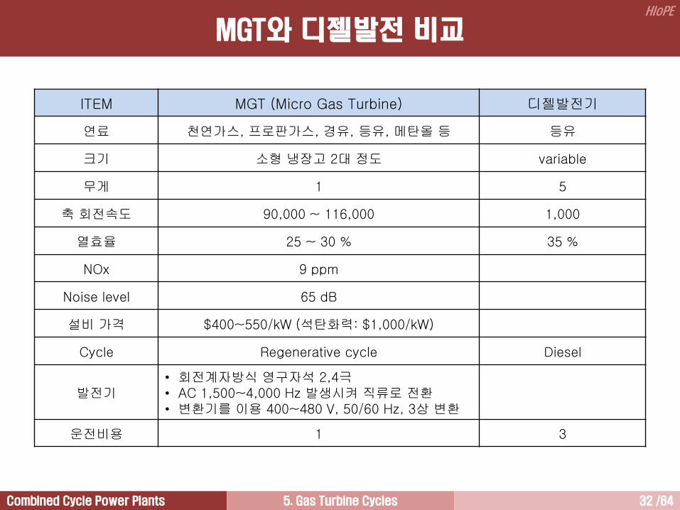
ITEM MGT (Micro Gas Turbine) 디젤발전기
연료 천연가스, 프로판가스, 경유, 등유, 메탄올 등 등유
크기 소형 냉장고 2대 정도 variable
무게 1 5
축 회전속도 90,000 ~ 116,000 1,000
열효율 25 ~ 30 % 35 %
NOx 9 ppm
Noise level 65 dB
설비 가격 $400~550/kW (석탄화력: $1,000/kW)
Cycle Regenerative cycle Diesel
발전기 • 회전계자방식 영구자석 2,4극 • AC 1,500~4,000 Hz 발생시켜 직류로 전환 • 변환기를 이용 400~480 V, 50/60 Hz, 3상 변환
운전비용 1 3
MGT와 디젤발전 비교

Combined Cycle Power Plants 5. Gas Turbine Cycles 33 /64
HIoPE
1 전력시장 자유화 통신분야: 이동전화와 인터넷 같은 무정부주의적 기술에 중앙집중화 통제 시스템 굴복
발전분야: 전력시장 자유화, 환경운동, 기술진보에 의해 통신분야와 같은 변화 시작 분산형 발전 확대
국가별 현황
미국: 절반이상의 주정부 경쟁체제로 전환
EU: 회원국가들간 전력도매시장 일부분 개방
개발도상국: 민영화 적극 추진 (인도, 아르헨티나 등)
2 환경규제 강화
미국: 석탄화력 규제치 만족 불가 (2000년 현재 절반 이상의 전력 석탄화력 이용 생산)
EU: 미국보다 강도 높게 청정 발전원 채택 강제
3 신기술 개발
공기베어링 (미국 Capstone 社)
변환기(Inverter) 감속기어 배제
재생사이클 열효율 향상
4 경쟁력 확보
막대한 송전손실 배제
폐열 이용 가능 Co-generation System
5 안정적 전력 공급 희망
선진국을 중심으로 정전문제 중요 사안으로 부각
지역적으로 안정성 문제 부각 California(USA), Kobe(Japan)
미개발국 대규모 자본투자가 요구되는 중앙집중화 발전방식 배제
대만 반도체업체 정전피해 사례: 피해액; 3억 대만달러(120억원), 정전시간; 2시간, 일시; 2000.12.25
피해장소; 신주 과학단지(대만 실리콘밸리), 피해업체 수; 6
The efficiency of a small gas turbine is usually much lower
than a large unit because of the limitation of the TIT and the
lower component efficiencies.
지역분산형 발전 확산 배경
Combined Cycle Power Plants 5. Gas Turbine Cycles 34 /64
HIoPE
AIR BEARING
Air is used as a lubricant
• Lube oil system is not required
• System becomes much simpler
• No maintenance, such as oil replacement and oil supplement, is required
INVERTER
High frequency alternating current is produced at a generator
Then, it converted into direct current
And then, it converted into alternating current of 50 or 60 Hz by the inverter
• Reduction gear used for high rpm machines is not required
• Structure of the machine becomes simpler
REGENERATIVE CYCLE OF GAS TURBINE ENGINE
The thermal efficiency is increased greatly by the addition of a device for transferring energy from the hot
turbine exhaust gas to the air leaving the compressor
The typical thermal efficiency of previous microturbines, rating of lower than 100 kW, was 15%. But, it is
improved up to 25-30% by the adoption of regenerative cycle
New Technologies for MGT
Combined Cycle Power Plants 5. Gas Turbine Cycles 35 /64
HIoPE
1 세금
다수의 대형 석탄발전소에 대한 탄소세 면제 및 기금 지원
미국: 기존발전소 환경규제로부터 면제해 주는 포기각서를 통해 간접지원
EU: 지원기금 납세자들로부터 직접 염출
초소형 발전 경쟁력확보를 위하여 왜곡된 세금제도 개선 필요
2 표준화 (기술기준)
초소형 발전기 소유자가 전력을 사용하지 않을 때 남는 전기 송전선에 보내기 위한 지능형 전자통제장비 필요
현재 이에 대한 국가기준을 마련한 나라 매우 적음
초소형 발전기 제조업체와 소유자는 전력을 사고 팔 수 있는 권한을 획득하기 위하여 무수한 문제 직면
기존 전력업체의 새로운 경쟁자에 대한 훼방
사이비 안전문제 제기
기나긴 허가절차 부과
부당한 요금 요구
각국 정부 적절한 기준 제정 필요
3 규제정책
각종 규제 난립
주정부간 전력매매에 대한 조정작업 미실시
단일 규제기관 부재 - 시장 신규진입 방해
첨두부하용 비축용량 보유 요구사항
규제철폐 및 제도개선 초소형 발전 기존시장 진입 적극 권장
지역분산형 발전 장애물
Combined Cycle Power Plants 5. Gas Turbine Cycles 36 /64
HIoPE
Regenerative Cycle 2
Combined Cycle 5
Simple Cycle 1
Intercooled Cycle 4
Reheat Cycle 3
Closed Cycle 6
Combined Cycle Power Plants 5. Gas Turbine Cycles 37 /64
HIoPE
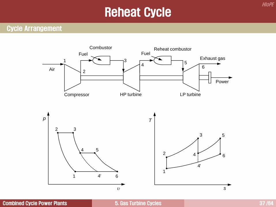
Reheat Cycle
Fuel Reheat combustor
LP turbine
Power
Exhaust gas 5
4 6
Compressor
Fuel
Combustor
Air
1
2
3
HP turbine
Cycle Arrangement
p
2
1
T
s
3
6 1
2
5
6
4 5 4
3
4
4
Combined Cycle Power Plants 5. Gas Turbine Cycles 38 /64
HIoPE
A Typical Reheat Cycle Gas Turbine for Power Generation - GT26 Gas Turbine
Reheat Cycle
Combined Cycle Power Plants 5. Gas Turbine Cycles 39 /64
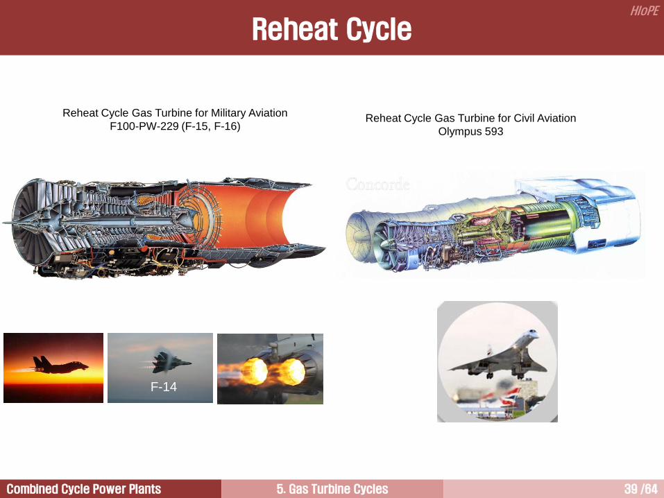
HIoPE
F-14
Reheat Cycle Gas Turbine for Military Aviation
F100-PW-229 (F-15, F-16)
Reheat Cycle
Reheat Cycle Gas Turbine for Civil Aviation
Olympus 593
Combined Cycle Power Plants 5. Gas Turbine Cycles 40 /64
HIoPE
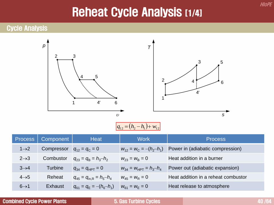
Cycle Analysis
Reheat Cycle Analysis [1/4]
Process Component Heat Work Process
12 Compressor q12 = qC = 0 w12 = wC = (h2h1) Power in (adiabatic compression)
23 Combustor q23 = qB = h3h2 w23 = wB = 0 Heat addition in a burner
34 Turbine q34 = qHPT = 0 w34 = wHPT = h3h4 Power out (adiabatic expansion)
45 Reheat q45 = qin,R = h5h4 w45 = wR = 0 Heat addition in a reheat combustor
61 Exhaust q61 = qE = (h6h1) w61 = wE = 0 Heat release to atmosphere
121212 whhq
p
2
1
T
s
3
6 1
2
5
6
4 5 4
3
4
4
Combined Cycle Power Plants 5. Gas Turbine Cycles 41 /64
HIoPE
11
121
max
c
ct
TC
w
p 1
3
T
Tt
1
rc1
2
p
pr
0 5 10 15 20Pressure Ratio [r]
0.0
0.5
1.0
1.5
2.0
2.5
Sp
ecific
Wo
rkO
utp
ut[w
/CT
]
t = 2
t = 3
t = 4
t = 5
Reheat cycle
Simple cycle
sys
p1
Reheat Cycle Analysis [2/4]
0 5 10 15 20Pressure Ratio [r]
0.0
0.1
0.2
0.3
0.4
0.5
0.6
Th
erm
alE
ffic
ien
cy
Simple cycleefficiency
t = 2
t = 3
t = 4
t = 5
ctct
cctth
/2
1/112
Combined Cycle Power Plants 5. Gas Turbine Cycles 42 /64
HIoPE
An increase of specific work output can be obtained by splitting the expansion and reheating the gas
between the high pressure and low pressure turbines.
The increase of specific work output can be seen in p- diagram.
The turbine work increase is obvious from the fact that the vertical distance between any pair of constant
pressure lines increases as the entropy increases. Thus,
(T3T4) + (T5 T6) (T3 T4’)
The shaft length becomes longer and the control of shaft vibration becomes difficult.
The maximum temperature in low pressure turbine is the same as in high pressure turbine.
Thermal efficiency of the reheat cycle is lower than that of the simple cycle. This is because the reheat
cycle is made by the combination of a simple cycle and a less efficient cycle which is operated over a lower
temperature range.
Reheat Cycle Analysis [4/4]

Combined Cycle Power Plants 5. Gas Turbine Cycles 43 /64
HIoPE
Regenerative Cycle 2
Combined Cycle 5
Simple Cycle 1
Intercooled Cycle 4
Reheat Cycle 3
Closed Cycle 6
Combined Cycle Power Plants 5. Gas Turbine Cycles 44 /64
HIoPE
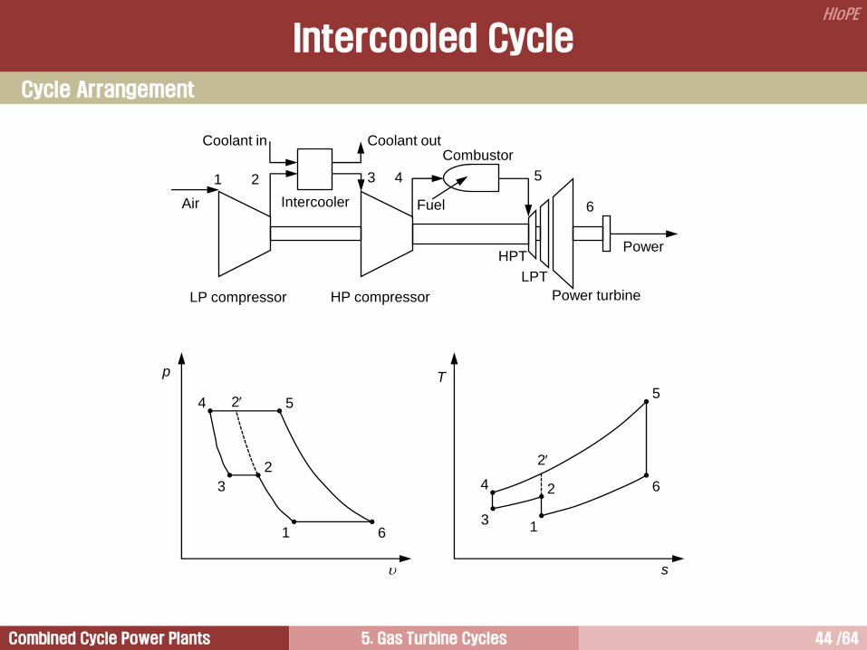
Intercooled Cycle
HP compressor
Fuel
Combustor
Power turbine
Air
Power
Intercooler
Coolant in Coolant out
HPT
LP compressor
LPT
1 2 3 4 5
6
Cycle Arrangement
p
2
1
T
s
3
6 1
2
5
6
4 5
4
3
2
2
Combined Cycle Power Plants 5. Gas Turbine Cycles 45 /64
HIoPE
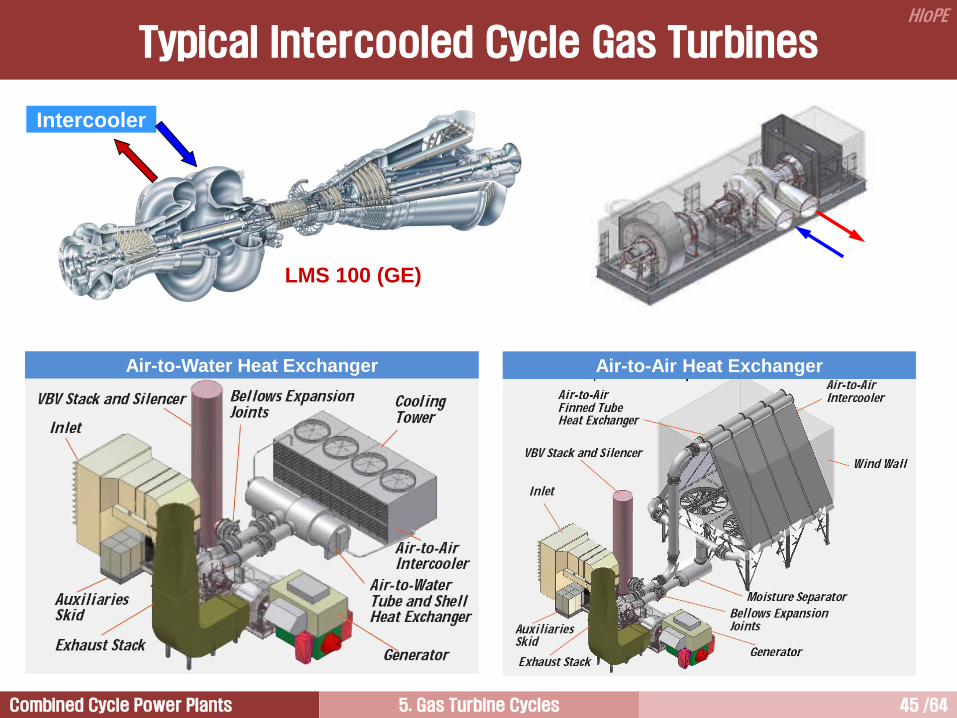
Typical Intercooled Cycle Gas Turbines
Air-to-Water Heat Exchanger Air-to-Air Heat Exchanger
Intercooler
LMS 100 (GE)
Combined Cycle Power Plants 5. Gas Turbine Cycles 46 /64
HIoPE
The specific work output of a gas turbine may be improved substantially by reducing the work of
compression.
If, therefore, the compression process is carried out with intercooling, the work of compression will be
reduced, as can be seen in p- diagram.
The compressor work decrease is obvious from the fact that the vertical distance between any pair of
constant pressure lines decreases as the entropy decreases. Thus,
(T2T1) + (T4 T3) < (T2′ T1)
Heat is extracted by an intercooler between the first and second compressors.
Rejecting heat worsens SFC, since more fuel should be burnt to raise cooler compressor delivery air to any
given TIT.
Therefore, the thermal efficiency of the intercooled cycle will be less than that for a simple cycle.
Intercooling is useful when the pressure ratios are high and the efficiency of the compressor is low.
Intercooled Cycle

Combined Cycle Power Plants 5. Gas Turbine Cycles 47 /64
HIoPE
Intercooled Cycle Analysis [1/5]
Cycle Analysis
Process Component Heat Work Process
12 LP compressor q12 = qC = 0 w12 = wLPC = (h2h1) Power supply in a LP compressor
23 Intercooler q23 = qIC = (h3h2) w23 = wIC = 0 Heat rejection in an intercooler
34 HP compressor q34 = qC = 0 w34 = wHPC = (h4h3) Power supply in a HP compressor
45 Combustor q45 = qB = h5h4 w45 = wB = 0 Heat addition in a burner
56 Turbine q56 = qT = 0 w56 = wT = h5h6 Power out (adiabatic expansion)
61 Exhaust q61 = qE = (h6h1) w61 = wE = 0 Heat release to atmosphere
121212 whhq
p
2
1
T
s
3
6 1
2
5
6
4 5
4
3
2
2
Combined Cycle Power Plants 5. Gas Turbine Cycles 48 /64
HIoPE
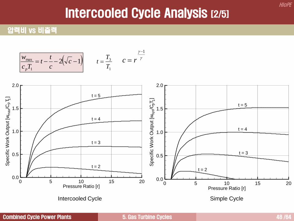
압력비 vs 비출력
Simple Cycle Intercooled Cycle
0 5 10 15 20Pressure Ratio [r]
0.0
0.5
1.0
1.5
2.0
Sp
ecific
Wo
rkO
utp
ut[w
/CT
]
t = 2
t = 3
t = 4
t = 5
max
p1
0 5 10 15 20Pressure Ratio [r]
0.0
0.5
1.0
1.5
2.0
Sp
ecific
Wo
rkO
utp
ut[w
/CT
]sys
1p
t = 2
t = 3
t = 4
t = 5
121
max cc
tt
Tc
w
p 1
3
T
Tt
1
rc
Intercooled Cycle Analysis [2/5]
Combined Cycle Power Plants 5. Gas Turbine Cycles 49 /64
HIoPE
압력비 vs 효율
0 5 10 15 20Pressure Ratio [r]
0.0
0.1
0.2
0.3
0.4
0.5
0.6
Th
erm
alE
ffic
ien
cy
Simple cycleefficiency
t = 2
t = 3
t = 4
t = 5
0 5 10 15 20Pressure Ratio [r]
0.0
0.1
0.2
0.3
0.4
0.5
0.6
Th
erm
alE
ffic
ien
cy
t = 2
t = 3
t = 4
t = 5
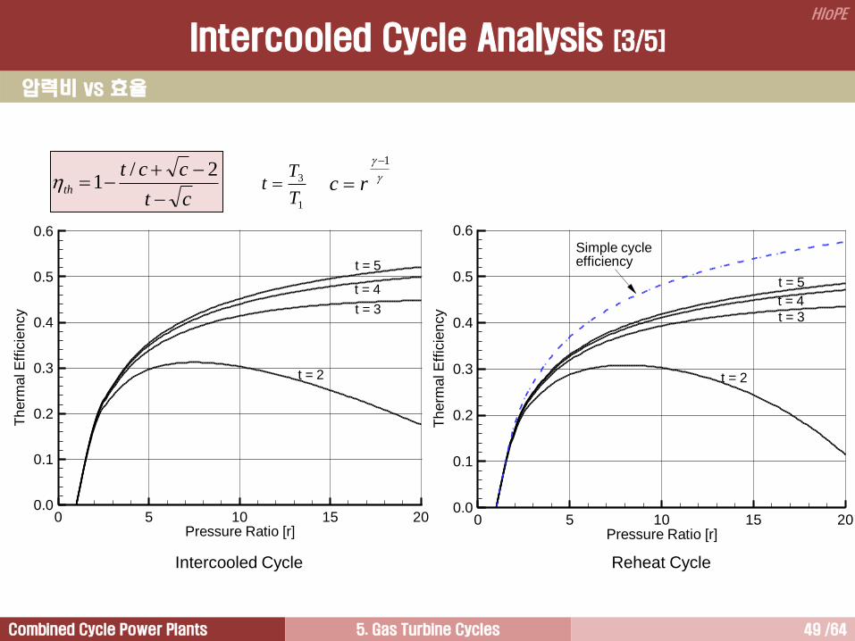
Intercooled Cycle Reheat Cycle
1
3
T
Tt
1
rcct
cctth
2/1
Intercooled Cycle Analysis [3/5]

Combined Cycle Power Plants 5. Gas Turbine Cycles 50 /64
HIoPE
A Typical Spray Intercooling Gas Turbine
LM6000-SPRINT Gas Turbine
LM6000 (GE)
Intercooled Cycle Analysis [4/5]

Combined Cycle Power Plants 5. Gas Turbine Cycles 51 /64
HIoPE
Spray Intercooling
Intercooling can also be accomplished by fog spraying atomized water between the HP and LP
compressors.
GE LM6000-SPRINT is one example of such a system.
Water in injected through 24 spray nozzles.
Water is atomized to a droplet diameter of less than 20 microns using high-pressure air taken from the
eighth-stage of HP compressor.
Injecting water significantly reduces the compressor outlet temperature.
The result is higher output and better efficiency.
Output increases of more than 20% and efficiency increases of 3.9% are possible on 90F(32C) day.
Intercooled Cycle Analysis [5/5]
Combined Cycle Power Plants 5. Gas Turbine Cycles 52 /64
HIoPE
Regenerative Cycle 2
Combined Cycle 5
Simple Cycle 1
Intercooled Cycle 4
Reheat Cycle 3
Closed Cycle 6
Combined Cycle Power Plants 5. Gas Turbine Cycles 53 /64
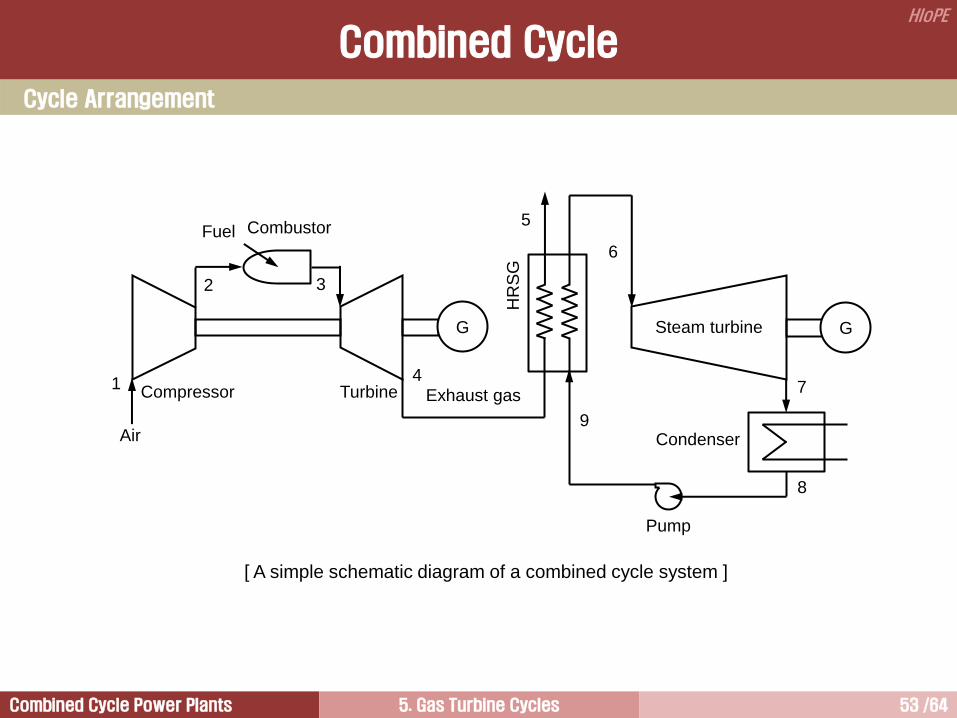
HIoPE
[ A simple schematic diagram of a combined cycle system ]
Compressor
Fuel Combustor
Turbine
Air
Steam turbine
Exhaust gas 1
2
4
3
G G
HR
SG
5
6
7
8
9 Condenser
Pump
Combined Cycle
Cycle Arrangement
Combined Cycle Power Plants 5. Gas Turbine Cycles 54 /64
HIoPE
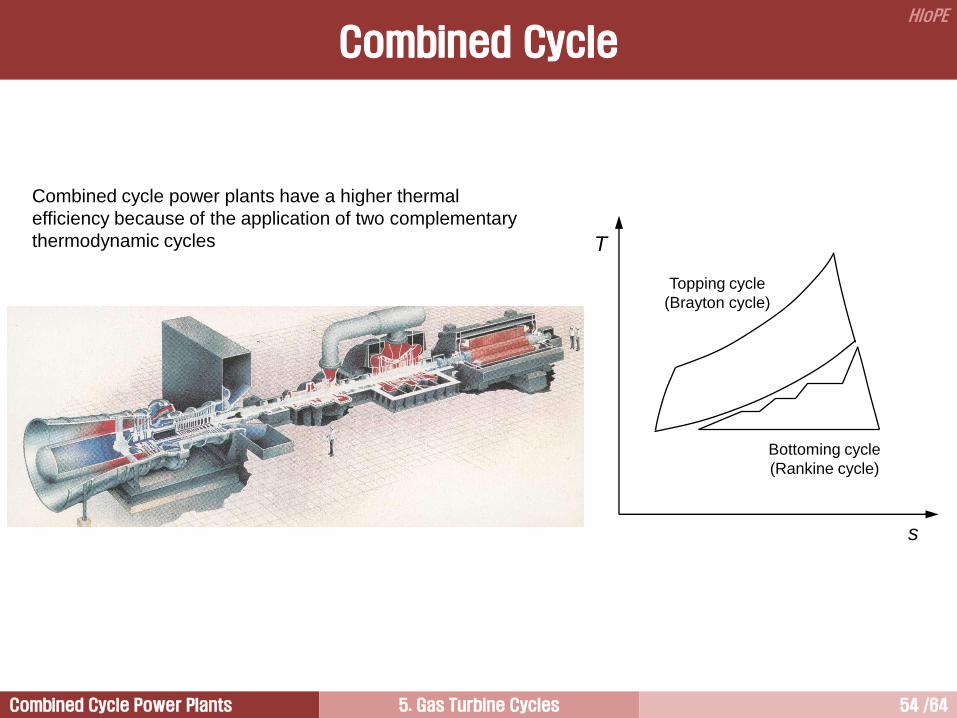
Combined cycle power plants have a higher thermal
efficiency because of the application of two complementary
thermodynamic cycles
Combined Cycle
T
s
Topping cycle
(Brayton cycle)
Bottoming cycle
(Rankine cycle)
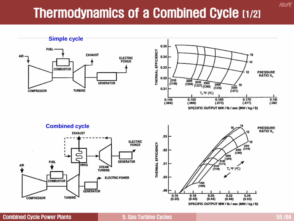
Combined Cycle Power Plants 5. Gas Turbine Cycles 55 /64
HIoPE
Simple cycle
Combined cycle
Thermodynamics of a Combined Cycle [1/2]
Combined Cycle Power Plants 5. Gas Turbine Cycles 56 /64
HIoPE
In simple cycle application, thermal efficiency increases with the pressure ratio at a given TIT.
For a given pressure ratio, thermal efficiency decrease as the TIT increases. This is because the lager
amount of cooling air for turbine blade is required as the TIT increases.
The pressure ratio resulting in maximum output and maximum efficiency change with TIT.
The higher the pressure ratio, the greater benefits for a given TIT.
The power increases with the TIT at a given pressure ratio. However, efficiency decrease because the
flow of the cooling air extracted increase with the TIT.
Simple cycle
Combined cycle
In combined cycle applications, pressure ratio have a less pronounced effect on efficiency.
As pressure ratio increases, specific power decreases.
Thermal efficiency increases with firing temperature.
The optimum cycle parameters for combined cycle are different from simple cycle.
Simple cycle efficiency is achieved with high pressure ratios. However, combined cycle efficiency is
obtained with more modest pressure ratios and higher TITs.
Thermodynamics of a Combined Cycle [2/2]
Combined Cycle Power Plants 5. Gas Turbine Cycles 57 /64
HIoPE
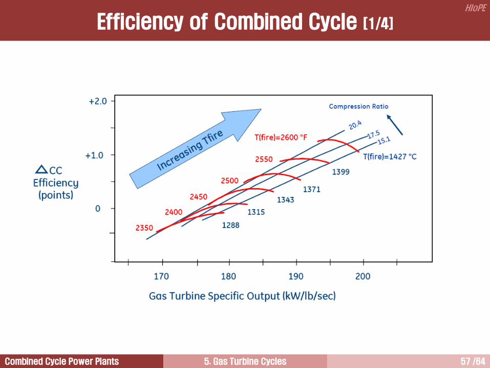
Efficiency of Combined Cycle [1/4]
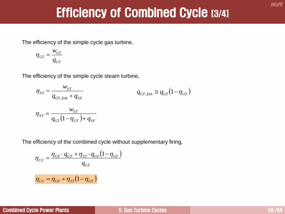
Combined Cycle Power Plants 5. Gas Turbine Cycles 58 /64
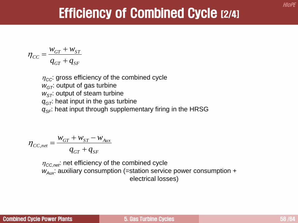
HIoPE
SFGT
STGTCC
ww
CC: gross efficiency of the combined cycle
wGT: output of gas turbine
wST: output of steam turbine
qGT: heat input in the gas turbine
qSF: heat input through supplementary firing in the HRSG
SFGT
AuxSTGTnetCC
www
,
CC,net: net efficiency of the combined cycle
wAux: auxiliary consumption (=station service power consumption +
electrical losses)
Efficiency of Combined Cycle [2/4]
Combined Cycle Power Plants 5. Gas Turbine Cycles 59 /64
HIoPE
Efficiency of Combined Cycle [3/4]
The efficiency of the simple cycle gas turbine,
GT
GTGT
q
w
The efficiency of the simple cycle steam turbine,
SFExhGT
STST
w
,
GTGTExhGT qq 1,
SFGTGT
STST
w
1
The efficiency of the combined cycle without supplementary firing,
GT
GTGTSTGTGTCC
q
1
GTSTGTCC 1
Combined Cycle Power Plants 5. Gas Turbine Cycles 60 /64
HIoPE
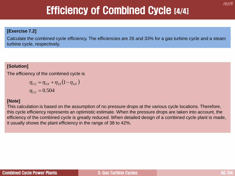
[Exercise 7.2]
Calculate the combined cycle efficiency. The efficiencies are 26 and 33% for a gas turbine cycle and a steam
turbine cycle, respectively.
[Solution]
The efficiency of the combined cycle is
[Note]
This calculation is based on the assumption of no pressure drops at the various cycle locations. Therefore,
this cycle efficiency represents an optimistic estimate. When the pressure drops are taken into account, the
efficiency of the combined cycle is greatly reduced. When detailed design of a combined cycle plant is made,
it usually shows the plant efficiency in the range of 38 to 42%.
GTSTGTCC 1
504.0CC
Efficiency of Combined Cycle [4/4]
Combined Cycle Power Plants 5. Gas Turbine Cycles 61 /64
HIoPE
Regenerative Cycle 2
Combined Cycle 5
Closed Cycle 6
Simple Cycle 1
Intercooled Cycle 4
Reheat Cycle 3

Combined Cycle Power Plants 5. Gas Turbine Cycles 62 /64
HIoPE
Closed Cycle

Combined Cycle Power Plants 5. Gas Turbine Cycles 63 /64
HIoPE
In a closed cycle, the working fluid is continuously recirculated. It may be air or another gas such as helium.
Usually, the gas turbine is of intercooled recuperated configuration.
However, the combustor is replaced by a heat exchanger as fuel can not be burnt directly.
The heat source for the cycle may be a separate combustor burning normally unsuitable fuels, such as coal,
a nuclear energy, etc.
On leaving the recuperator, the working fluid must pass through a pre-cooler where heat is rejected to an
external medium, such as sea water, to return it to the fixed inlet temperature, usually between 15C and
30C.
The pressure at inlet to the gas turbine is maintained against leakage from the system by an auxiliary
compressor supplying a large storage tank called an accumulator.
The high density of the working fluid at engine inlet enables very high power output, which is the main
benefit of the closed cycle.
Closed Cycle

Combined Cycle Power Plants 5. Gas Turbine Cycles 64 /64
HIoPE
질의 및 응답
작성자: 이 병 은 (공학박사) 작성일: 2015.02.11 (Ver.5) 연락처: [email protected]
Mobile: 010-3122-2262 저서: 실무 발전설비 열역학/증기터빈 열유체기술