PARAMETRIC THERMODYNAMIC ANALYSIS OF INTERCOOLED …€¦ · gas turbine (IcGT) and...
14
PARAMETRIC THERMODYNAMIC ANALYSIS OF INTERCOOLED AND INTERCOOLED-RECUPERATED GAS TURBINE BASED CYCLES 1 MITHILESH KUMAR SAHU, 1 TUSHAR CHAUDHARY, 1 ANUPAM KUMARI, 2 SANJAY 1 Ph.D. Scholar, Mechanical Engg. Deptt. NIT Jamshedpur; 2 Professor, Mechanical Engg. Department, National Institute of Technology, Jamshedpur, INDIA; E-mail: [email protected] ABSTRACT: - Gas turbine based power plants are considered as most promising and efficient source of power generation. In this paper, focus is on the performance evaluation of intercooled gas turbine (IcGT) and intercooled-recuperated gas turbine (IcRcGT) cycle. Performance of a gas turbine is mainly affected by the various parameters like pressure ratio, turbine inlet temperature and ambient conditions. The evaluation is done on the basis of thermodynamic analysis, computed with the help of energy and exergy analysis. The analysis of various cycle components is done by adopting the energy and exergy balance approach. When operating at high turbine-inlet-temperature (TIT) turbine blade cooling is required so the cooled gas turbine has been analyzed where turbine blades are cooled by compressor bled air. Blade cooling increases the life of blade and reduces gas turbine work output due to mixing losses. The recuperation technique has also been integrated to the cycle for utilization of high temperature turbine exhaust. The energy efficiencies found for IcGT cycle is 35.07% and for IcRcGT cycle it is 43.1% respectively. 1. INTRODUCTION Gas turbine burning natural gas is a promising energy conversion system for power generation due to its lower emission characteristics as the energy it provides is clean. 21 st century requires such a source of power generation which fulfills the need of power and provides energy security along with lower emission. Its high energy conversion efficiency and large output with reduced emission makes it the need of future power demand [1]. Exergy analysis has been integrated with the energy analysis as a useful tool to determine thermodynamic inefficiencies in components of the thermodynamic cycles. In this field of research H. Chandra et.al. have reported the energy and exergy analysis of simple closed Brayton thermal power cycle [2] and have plotted results showing energy and exergy destroyed in various components of the cycle. Adoption of higher turbine inlet temperatures in an effort to improve thermodynamic energy conversion efficiency requires the adoption of advanced blade cooling methods. Blade cooling allows for high inlet temperature of turbine but also causes a decrease in net power output [3]. The reduction in net work is overcome by implementing the intercooling. The use of intercooler reduces the power requirement of compressor, the reduction in compression work results in a corresponding increase in output of the gas turbine [4]. The efficiency of gas-
Transcript of PARAMETRIC THERMODYNAMIC ANALYSIS OF INTERCOOLED …€¦ · gas turbine (IcGT) and...
PARAMETRIC THERMODYNAMIC ANALYSIS OF INTERCOOLED AND INTERCOOLED-RECUPERATED GAS
TURBINE BASED CYCLES
1MITHILESH KUMAR SAHU, 1TUSHAR CHAUDHARY, 1ANUPAM KUMARI, 2SANJAY
1 Ph.D. Scholar, Mechanical Engg. Deptt. NIT Jamshedpur;
2 Professor, Mechanical Engg. Department, National Institute of Technology, Jamshedpur, INDIA;
E-mail: [email protected]
ABSTRACT: - Gas turbine based power plants are considered as most promising and efficient source of power generation. In this paper, focus is on the performance evaluation of intercooled gas turbine (IcGT) and intercooled-recuperated gas turbine (IcRcGT) cycle. Performance of a gas turbine is mainly affected by the various parameters like pressure ratio, turbine inlet temperature and ambient conditions. The evaluation is done on the basis of thermodynamic analysis, computed with the help of energy and exergy analysis. The analysis of various cycle components is done by adopting the energy and exergy balance approach. When operating at high turbine-inlet-temperature (TIT) turbine blade cooling is required so the cooled gas turbine has been analyzed where turbine blades are cooled by compressor bled air. Blade cooling increases the life of blade and reduces gas turbine work output due to mixing losses. The recuperation technique has also been integrated to the cycle for utilization of high temperature turbine exhaust. The energy efficiencies found for IcGT cycle is 35.07% and for IcRcGT cycle it is 43.1% respectively. 1. INTRODUCTION Gas turbine burning natural gas is a promising energy conversion system for power generation due to its lower emission characteristics as the energy it provides is clean. 21st century requires such a source of power generation which fulfills the need of power and provides energy security along with lower emission. Its high energy conversion efficiency and large output with reduced emission makes it the need of future power demand [1]. Exergy analysis has been integrated with the energy analysis as a useful tool to determine thermodynamic inefficiencies in components of the thermodynamic cycles. In this field of research H. Chandra et.al. have reported the energy and exergy analysis of simple closed Brayton thermal power cycle [2] and have plotted results showing energy and exergy destroyed in various components of the cycle. Adoption of higher turbine inlet temperatures in an effort to improve thermodynamic energy conversion efficiency requires the adoption of advanced blade cooling methods. Blade cooling allows for high inlet temperature of turbine but also causes a decrease in net power output [3]. The reduction in net work is overcome by implementing the intercooling. The use of intercooler reduces the power requirement of compressor, the reduction in compression work results in a corresponding increase in output of the gas turbine [4]. The efficiency of gas-

turbine cycles can be enhanced by the use of auxiliary equipment such as intercoolers, regenerators, and reheaters. These devices are bulky hence expensive, however, and economic considerations usually preclude their use. Intercooling and recuperation are known to be the means to improve specific output and efficiency respectively of a gas turbine. Colin F. Mc Donald et. al. [5] has dealt with the utilization of recuperated and regenerated engine cycle for high efficiency gas turbine in 21st century. R. Bhargava et. al [6] reported the approach to increase the efficiency with intercooling and cogeneration process which leads the integration of this process with the simple Brayton cycle for higher degree of performance. The energy and exergy analysis of steam cooled reheat gas steam combined cycle [7] reports that using closed loop steam cooling the plant thermal efficiency can be improved up to 62%. The effect of turbine blade cooling on cycles [8], defining the cooled turbine efficiency [9], and J.H. Horlock [10] worked on amount of blade coolant air required. Sanjay et. al. [11] worked on comparative performance analysis of cogeneration gas turbine cycle for different blade cooling means. Considering the above literature and by applying energy and exergy balance approach proposed cycles have been analyzed. NOMENCLATURE
pc specific heat at constant pressure
(��
��∙ �)
,X HE total exergy supplied (kW)
ex
specific exergy of the stream
(��
��)
h specific enthalpy of the stream
(��
��)
.
m mass flow rate (��
�)
p pressure (bar) p reference or ambient pressure
(kPa)
T0 reference or ambient temperature
Q
heat transfer rate (kW)
HQ heat supplied by fuel (kW)
Hq heat gain by working fluid (kW)
s specific entropy (��
��∙ �)
S entropy (��
�)
genS
entropy generation (
��
�)
S(stream)
represents energy content in a stream computed by the product of mass flow rate and enthalpy of that stream (kW)
T
temperature (K)
T reference or ambient temperature (K)
W work (kW) SUBSCRIPTS a air/ambient c compressor comb combustion chamber ex exergy d destruction Gen generation f fuel G gas in inlet Out outlet Ic intercooler sat saturated T turbine w water Ι first law

ΙΙ second law 1, 2, 3…
state points
GREEK SYMBOLS thermodynamic function effectiveness efficiency availability per unit mass of
gas Ωd exergy destruction rate
ACRONYMS A alternator BGT brayton gas turbine cycle C Compressor CMBEXT combustion exit FRMRCP from recuperator GTCOMB gas turbine combustion chamber
HPT high pressure turbine HPC high pressure compressor HP NOZZ high pressure turbine nozzle HP ROTR high pressure turbine rotor I irreversibility IPT intermediate pressure turbine IC intercooler IcGT intercooled gas turbine IcRcGT intercooled recuperated gas
turbine IPNOZZ intermediate pressure turbine
nozzle IPROTR intermediate pressure turbine rotor LPC low pressure compressor PT power turbine RECUP recuperator R_BYPS recuperator bypass TORCUP to recuperator WATRES water reservoir
2. SYSTEM DESCRIPTION Fig.1 shows schematic diagram of intercooled gas turbine (IcGT) cycle. The key features of this proposed cycle is water cooled intercooler in between two stages of compressors. Also the expansion stages of gas turbine incorporate compressor bled air cooling. The coolant air is bled from the high pressure compressor (HPC) at an appropriate pressure level and is allowed to enter the hollow gas turbine blades from the root. The coolant air is passing through a serpentine path before exiting the blade at its tip and mixing with the main flow gases. Other aspects of cycle are similar to conventional gas turbine cycle. Fig.2 shows a schematic diagram of an intercooled-recuperated gas turbine cycle. This cycle differs from the previously discussed proposed cycle (IcGT) as it incorporates recuperator which successfully extracts a significant amount of thermal energy exiting the power turbine (PT). This feature is achieved by the help of a splitter unit, which divides the HPC exit stream to the recuperater unit and MIXRCP unit. 3. MODELING AND GOVERNING EQUATIONS 3.1 Gas model The inlet ambient air has been assumed to be at 1 bar and 288K with relative humidity of 50% and natural gas as a fuel. Gas model is based on the assumption that specific heat of gas is a function of temperature at constant pressure and is given by the polynomial:

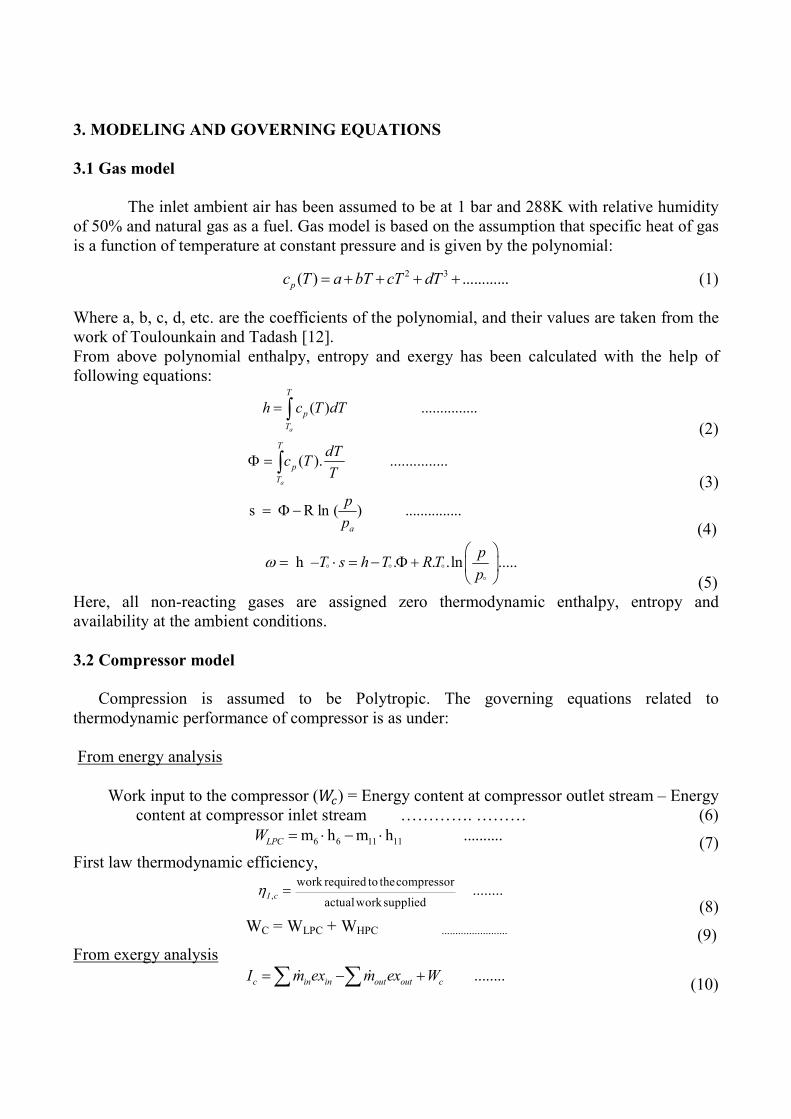
3. MODELING AND GOVERNING EQUATIONS 3.1 Gas model The inlet ambient air has been assumed to be at 1 bar and 288K with relative humidity of 50% and natural gas as a fuel. Gas model is based on the assumption that specific heat of gas is a function of temperature at constant pressure and is given by the polynomial:
2 3( ) ............p T a bT cT dc T (1) Where a, b, c, d, etc. are the coefficients of the polynomial, and their values are taken from the work of Toulounkain and Tadash [12]. From above polynomial enthalpy, entropy and exergy has been calculated with the help of following equations:
( ) ...............a
T
p
T
h c T dT (2)
( ). ...............a
T
p
T
dTc T
T
(3)
s R ln ( ) ...............
a
p
p
(4)
. ln ..... h – . .
ph T R
ps TT
(5) Here, all non-reacting gases are assigned zero thermodynamic enthalpy, entropy and availability at the ambient conditions.
3.2 Compressor model Compression is assumed to be Polytropic. The governing equations related to thermodynamic performance of compressor is as under: From energy analysis
Work input to the compressor (��) = Energy content at compressor outlet stream – Energy content at compressor inlet stream …………. ……… (6)
6 6 11 11m h m h ..........LPCW (7)
First law thermodynamic efficiency,
,
work required to thecompressor
actualworksupplied........I c
(8)
WC = WLPC + WHPC ........................ (9)
From exergy analysis ........c in in out out cI ex ex Wm m
(10)

which gives,
, ( ) .............gen c in outT S mT s s (11)
The second law efficiency of compressor is as under:
, 1 .................cII c
c
I
W
(12)
3.3 Intercooler model The increase in cycle net-work output may be achieved by the adoption of multi-stage intercooled compressor layout since inter-cooler saves some work of compression. The intercooler may be surface or evaporative type, with surface type being more common. Practically an inter-cooler effectiveness is always less than 100% and thus Intercooling is always imperfect and pressure losses occur in both the fluid streams. The following assumptions have been made for the mathematical modeling of intercooler: Cooling medium, water is taken at ambient conditions.
Intercooler selected for the analysis is of surface type.
Intercooler is a counter flow liquid-air type heat exchanger
Losses in intercooler are accounted by assuming appropriate values of intercooler-
effectiveness ( ) and pressure drop (∆p) in the air-stream side as detailed in Table 1. The effectiveness of intercooler is given by the following equation:
, ,
ic
, ,
( ) ( )...............
( ) – ( )
ic a in ic a out
ic a in ic w in
T T
T T
(13)
Energy balance of intercooler gives:
, , , , , , , ,(( ) ) {( ) ( ) } 0 ........ . . . . .ic a p a ic ic a in ic a out ic w p w ic w out ic w inm c T T m c T T (14)
Exergy destroyed is given as:
, , , , , ,( . {( Ω ) ) )( ( } {() ) ) } ......(ic d ic a in ic a in ic a out ic w ic w in ic w outm m (15)
....ic in in out outI exm exm (16)
3.4 Combustion chamber model The combustion process is accompanied by certain losses including incomplete combustion and loss of pressure. The fuel flow has been determined from the mass and energy balance, and the exergy destroyed has been obtained from the exergy balance.
...............comb a fm m m
(17)
Combustion chamber in-efficiency leads to energy and exergy loss within the component. Energy and exergy balance method has been used to determine the energy and exergy loss in the GTCOMB as under: Energy loss = (Energy content at outlet stream) – (Energy content at inlet stream)
CMBEXT CMBEX 2T 244 f.h - .hEnergyloss = m - .CV ......m m (18)
Energy loss
Energy suppliedPercentage energy loss ...
(19)

Exergy balance is given as:
,0 (1 .) .) .(H in out gen c
s
Tq m ex ex T S
T
(20)
. . 1 ....comb in in out out f
H
m m mT
I ex ex CVT
(21) which gives,
,Exergy destroyed due to irreversibility gen cmT S
(22) The second law efficiency,
,
,
1 ......combII comb
X H
I
E
(23) 3.5 Cooled Gas Turbine model Gas turbine operating at high temperature needs cooling for safe operation. The purpose of the blade cooling is to keep the blade temperature to a safe level, and blade cooling ensures a long creep life, low oxidation rates, and low thermal stresses. The blade coolant requirement model has been adopted from author’s previous work [4]:
.
, ,
., ,cos
c g p g g i b
in sa
p c b c ig
S c T TmSt F
t cm
(24)
The expansion process in the turbine has been modeled as under: First law efficiency of gas turbine is given as under:
Ι ..........T
H
W
q
(25) Exergy balance equation for turbine,
......Δin outT genW m ex ex T S (26)
...T in in out out TI ex ex Wm m (27)
Which gives,
Δ ( ) ....out ingenT S mT s s (28)
, 1 ........TII T
in in out out
I
ex exm m
(29)
4. Result and Discussion: - Calculations made by using the detailed energy and exergy balance equation gives the energy loss/utilized in different components of cycle and the exergy destruction of the cycle. Fig. 1 and Fig. 2 shows the cycle configuration of the IcGT and IcRcGT respectively, which explain to and from motion of the streams. Table 1 and 2 show the state points of the cycle in terms of its

Table 1: Operating parameters of IcGT cycle
STREAM FROM TO P (bar) T (K) ṁ (kg/s)h (kJ/kg) ex (kJ/kg)
SEA-IN - WATRES 1.72 288.55 88.19 2.1 70.47
S6 IPC INTCOL 3.19 415.89 62.99 129.09 116.74
S7 IPT PT 5.06 1116.3 64.45 936.51 610.99
S8 PT EXHDCT 1.04 790.92 64.45 555.11 238.12
s9 HPT IPT 7.67 1288.2 58.61 1152.1 798.49
s11 INDUCT IPC 0.99 287.99 62.99 0 0
S15 INTCOL HPC 3.06 305.1 62.99 17.18 92
S16 INTCOL WATRES 3.64 320.32 58.25 135.53 177.55
S17 WATRES INTCOL 3.79 294.97 58.25 29.3 176.09
S1 HPC GTCOMB 15.33 505.39 47.06 224.73 284.12
CMBEXT GTCOMB HPT 14.52 1644.1 48.52 1615.9 1207.1
AIR(dead) - INDUCT 1.01 288 62.99 0 0
HPNOZZ HPC HPT 15.33 505.39 7.68 220.65 280.04
IPROTR HPC IPT 8.96 427.89 1.16 141.3 205.9
HPROTR HPC HPT 15.33 505.39 2.41 220.65 280.04
IPNOZZ HPC IPT 8.96 427.89 4.66 141.3 205.9
Table 2: Operating parameters of IcRcGT cycle
STREAM FROM TO P (bar) T(K) ṁ(kg/s) h (kJ/kg) ex(kJ/kg)
S6 IPC INTCOL 3.19 415.89 62.99 129.09 116.74
S7 IPT PT 5.23 1129.3 64.18 952.96 620.02
S8 PT RECUP 1.04 790.92 64.18 555.11 238.1
s9 HPT IPT 7.94 1302.3 58.34 1171.2 812.26
s11 INDUCT IPC 0.99 287.99 62.99 0 0
EXH EXHDCT - 1.01 619.11 64.18 359.15 120.69
S12 RECUP EXHDCT 1.02 619.11 64.18 359.15 121.31
S15 INTCOL HPC 3.06 305.1 62.99 17.18 92
S16 INTCOL WATRES 3.64 320.32 58.25 135.53 177.55
S17 WATRES INTCOL 3.79 294.97 58.25 29.3 176.09
S1 HPC COLSPL 15.33 505.39 47.06 224.73 284.12
SEAOUT WATRES - 1.72 307.8 88.19 83.7 74.27
CMBEXT GTCOMB HPT 14.52 1644.1 48.25 1615.9 1207.1
S24 MIXRCP GTCOMB 14.87 753.63 47.06 479 342.66
AIR(dead) - INDUCT 1.01 288 62.99 0 0
R_BYPS COLSPL MIXRCP 15.33 505.39 2.35 220.65 280.04
HPNOZZ HPC HPT 15.33 505.39 7.68 220.65 280.04
IPROTR HPC IPT 8.96 427.89 1.16 141.3 205.9
HPROTR HPC HPT 15.33 505.39 2.41 220.65 280.04
IPNOZZ HPC IPT 8.96 427.89 4.66 141.3 205.9
TORCUP COLSPL RECUP 15.33 505.39 44.75 220.65 280.04
FRMRCP RECUP MIXRCP 14.87 766.35 44.71 492.87 427.37

temperature, pressure, flow rate, enthalpy and exergy. Table 3 relate to the performance parameters used for the analysis of cycle components.
Table 3: Performance parameters used for analysis of the proposed cycles.
Parameter Symbol Unit
kJ kg-1 k-1
kJ kg-1
Polytropic efficiency = 92.0 %
Mechanical efficiency = 98.5 %
Combustor efficiency = 99.5 %
Air fuel ratio = 43.44 (IcGT)
Air fuel ratio = 53.12 (IcRcGT)
Polytropic efficiency = 92.0 %
Exhaust pressure = 1.04 bar
Intercooler Effectiveness =0.9162 -
Recuperator Effectiveness =0.6017 -
Mass flow rate of water 58.258 kg/s
Mass flow rate of air 62.9988 kg/s
Gas properties
Compressor
Combustor
-
Gas turbine
( )pc f T
Enthalpy h ( ) dT pc T
Fig.3 is a pie chart which shows the energy distribution within the IcGT cycle. Fig.3 helps us to understand that the exhaust loss is 52.04% and the overall efficiency of cycle is 35.07%. The loss takes place in compressor; turbine and combustion chamber are 0.35%, 1.34% and 0.5% respectively. Fig.4 shows the energy balance of the IcRcGT the fig shows that exhaust stream takes away the 41.4% of total energy supplied and provides the cycle efficiency of 43.1%. The remaining part of energy is lost in other components like compressor, turbine and combustion chamber. Fig.5 shows the percentage of exergy destruction of different components within the IcGT cycle. To measure actual losses and to perform the accurate thermodynamic analysis, exergy analysis is advantageous. Exergy analysis provides the actual performance parameters of the cycle. In pie chart it can be clearly seen that the maximum amount of exergy supplied is destroyed in exhaust which amounts 27.3% of total exergy supplied and followed by the combustion chamber 19.5%. The sum of percentage of exergy destruction in compressor, turbine and intercooler amounts 10.5%.

0.5%
35.07%10.35%
1.34%
52.04%
0.35%
0.35%
Turbine Intercooler Compressor Net power Combustion Chamber Unaccounted Exhaust
Turbine loss (1.34%)
Compressor loss (0.35%)
Unaccounted loss (0.35%)
Combustion chamber loss (0.5%)
Heat carried away by intercooler
coolant (10.35%)
Net power o/p (35.07%)
Exhaust (52.04%)
Fig. 3: Percentage energy balance in intercooled gas turbine
41.4%
43.1%
0.56%
0.72%0.73%
0.33%0.5%
12.65%
Turbine Recuperator Intercooler Compressor Net power Combustion Chamber Unaccounted Exhaust
Turbine loss (0.73%)
Compressor loss (0.56%)
Unaccounted loss (0.33%)
Combustion chamber loss (0.5%)
Heat carried away by intercooler
coolant (12.65%)
Recuperator loss (0.72%)
Net power o/p (43.1%)
Exhaust (41.4%)
Fig. 4: Percentage energy balance in intercooled recuperated gas turbine

0.2%
42.5%
27.3%
4.3%
19.5%2.7%
3.5%
Compressor Intercooler Combustion chamber Turbine Exhaust Net power Output Unaccounted
Exergy destruction in intercooler (2.7%)
unaccounted loss (0.2%)
Combustion loss (19.5%)Turbine loss (4.3%)
Exhaust/ stack (27.3%)
Fig. 5: Component-wise percentage exergy destruction in intercooled gas turbine cycle.
Net power output (42.5%)
Compressor loss (3.5%)
Fig.6 depicts the exergy destruction of different component of IcRcGT cycle. From the chart it is clear that maximum amount of exergy is destroyed in exhaust gas stream 16.95% followed by that in the combustion chamber 8.3%. The summation of exergy destruction occurring in remaining cycle component turbine, compressor, recuperator, and intercooler amounts to 17.14 %. Fig.7 shows comparative data related to performance of intercooled gas turbine cycle with intercooled-recuperated gas turbine [8]. It shows that exergy efficiencies for intercooled gas turbine cycle (IcGT) is 42.5% and while that in IcRcGT cycle it enhances and is 52.25%. The exergy destruction associated with major components of both cycles (IcGT and IcRcGT) have been plotted. The graph shows that the exergy destruction in compressor for IcGT is 3.5% whereas for IcRcGT it is about 4.26%. The exergy destruction in gas turbine is around 4.3% in IcGT and 7.71% for IcRcGT. The exhaust gas loss in IcGT is higher as compared to IcRcGT, the reason being the absence of recuperator which partially utilizes heat content of exhaust gas stream. The sum total of exergy destruction in major cycle components (GTCOMB, GT, C and stack) is 37.27% for IcRcGT and 54.3% for IcGT.

52.25%
5.36%16.95%
1.97%7.71% 8.3%
3.2%4.26%
Compressor Intercooler Combustion Turbine Recuperator Exhaust(S12) Net Work Output Unacccounted
Compressor loss (4.26%)
Exergy loss in intercooler (3.2%)
Net power output (52.25%)
unaccounted loss(5.36%)
Combustion loss (8.3%)
Turbine loss (7.71%)
Recuperator loss (1.97%)
Exhaust/stack (16.95%)
Fig. 6: Component-wise percentage exergy destruction in intercooled recuperated gas turbine cycle.
GT C Comb GT Exhaust gas
0
5
10
15
20
25
30
35
40
45
50
55
60
65
Exe
rgy e
ffic
ien
cy a
nd e
xe
rgy
de
str
uct
ion
(%
)
IcGT Cycle IcRcGT Cycle
Exergy
efficiency Exergy destruction
rp,c
=15.33 bar
TIT=1644.11 K
Fig 7: Effect of cycle configuration on exergy efficiency and component wise exergy destruction.

5. CONCLUSION Based on the comprehensive thermodynamic analysis of complex intercooled recuperated gas turbine cycle, the following conclusions have been drawn: 1. Component level thermodynamic analysis suggests that losses arise due to irreversibility’s
within the components of the cycle. 2. The increase in energy efficiency and exergy efficiency has been observed in comparison to
the intercooled gas turbine cycle. 3. The Pressure loss is also taking into consideration and seen that the pressure loss is highest
in the recuperator and is around 0.46 bar followed by the combustion chamber around 0.35 bar and followed by that in intercooler in IcRcGT cycle.
4. Exergy destruction at component level is maximum in exhaust gas stream at 16.95% followed by combustion chamber at 8.30% in IcRcGT whereas in IcGT cycle it is 27.3% and 19.5% respectively.
5. Thermodynamic analysis of complex gas turbine cycle shows that a considerable amount of exergy is destroyed in exhaust that is a major loss of exergy supplied.
6. The utilization of turbine exhaust gas by using recuperator improves the cycle efficiency which can be seen in the fig 7 which shows the exergy efficiencies of the complex gas turbine cycles
7. REFERENCES
[1] Goktun S, Yavuz H. Thermal efficiency of a regenerative Brayton cycle with isothermal heat addition. Energy Converse. Mgmt. 1999:40:1259-1266. [2] H. Chandra , S.C. Kaushik and Y. Abhyankar , Energy and Exergy Analysis of Simple Closed Brayton Thermal Power Cycle. Journal of Mechanical Engg. 2012:3:35-40. [3] Amjed Ahmed, Mohammad Tariq, Thermal analysis of cooling effect on gas turbine blade, International journal of research in engineering and technology, 2014:03:603-610. [4] Sanjay, Y., Singh Onkar, and Prasad, B. N., influence of different means of turbine blade cooling on the thermodynamic performance of combined cycle. Applied Thermal Engineering, 2008:28: 2315-2326. [5] C. F. McDonald and D. G. Wilson, the Utilization of recuperated and regenerated engine cycle for high-efficiency gas turbine in the 21st century . [6] R.Bhargava, A.Peretto, a Unique Approach for Thermo economic Optimization of an Intercooled, Reheat, and Recuperated Gas Turbine for Cogeneration Applications. Journal of Engineering for Gas Turbines and Power, 2002; 124:881-891.

[7] Sanjay, Y., Singh Onkar, and Prasad, B. N., Energy and exergy analysis of steam cooled reheat gas-steam combined cycle, Applied Thermal Engineering, 2007;27: 2779-2790. [8] R.C.Wilcock, J.B. Young, J.H.Horlock, the Effect of Turbine Blade Cooling on the Cycle Efficiency of Gas Turbine Power Cycles. Journal of Engineering for Gas Turbines and Power 2005; 127:109-120. [9] J.B.Young, J.H.Horlock, Defining the Efficiency of a Cooled Turbine. Journal of Turbo machinery, 2006; 128:658-667. [10] J.H.Horlock, D.T.Watson, T.V.Jones, Limitations on Gas Turbine Performance Imposed by Large Turbine Cooling Flows. Journal of Engineering for Gas Turbines and Power, 2001; 123:487-494. [11] Sanjay, Onkar Singh, B.N. Prasad, “Comparative Performance Analysis of Cogeneration Gas Turbine Cycle for Different Blade Cooling Means” International Journal of Thermal Sciences, Volume 48, Issue 7, July 2009, 1432-1440. [12]Y.S.Touloukian,MakitaTadash,ThermophysicalPropertiesofMatter,TheTPRCDataSeries,vol.6,IFI/PLENUNM,NewYork,Washington,1970. [13] Arora, S., C., and Domkundwar, S. A Course in Power Plant Engineering, Dhanpat Rai and Sons, 1996. [14] P. K. Nag, “Engineering Thermodynamics”, Fourth edition, 2008. [15] Yunus A. Cengel, Michael A. Boles, “Thermodynamics: An Engineering Approach”, Fifth edition, 2006. [16] P.P. Walsh, P.Fletcher,“Gas Turbine Performance”, Second edition, 2004.