5. Datalink Layer in Local Area Networksee224/2012-2013/Notes/05_Datalink… · ·...
38
EE210 Data Communications and Computer Networks 1 5. Datalink Layer in Local Area Networks 5. Datalink Layer in Local Area Networks Most LANs use broadcast technology (i.e. multiple nodes share a channel). It must be determined which node can use the shared channel at any given time • when two or more nodes want to transmit at the same time, they are said to contend for the channel • if two or more nodes transmit at the same time, usually assumption is that all the transmissions collide ⇒ no transmission is successful
Transcript of 5. Datalink Layer in Local Area Networksee224/2012-2013/Notes/05_Datalink… · ·...

EE210 Data Communications and Computer Networks1
5. Datalink Layer in Local Area Networks5. Datalink Layer in Local Area Networks
Most LANs use broadcast technology (i.e. multiple nodes share a channel). It must be determined which node can use the shared channel at any given time
• when two or more nodes want to transmit at the same time, they are said to contend for the channel
• if two or more nodes transmit at the same time, usuallyassumption is that all the transmissions collide ⇒ no transmission is successful

EE210 Data Communications and Computer Networks2
Overview: Issues for Broadcast LANsOverview: Issues for Broadcast LANs
Overview of Local Area Networks?Basic topologies
Broadcast NetworksMAC and LLC SublayersThe 802.X standard
EthernetToken RingToken BusFDDIWireless LANs

EE210 Data Communications and Computer Networks3
LAN Overview: What Are LANs?
LANs are used to provide inexpensive and fast interconnection of distributed communities of DTEs(minicomputers, PCs, printers, telephones)
Usually localised within a single or a group of buildings
Since LANs are typically owned and maintained by one organisation they are also referred to as Private Data Networks
Because of the relatively short distances involved LANs can provide very high data transmission rates, even up to hundreds of Mbps, between networked DTEs

EE210 Data Communications and Computer Networks4
LAN Overview: Topologies
There are a number of different LAN topologies, each suited to particular application environments
Issues such as reliability, speed, cost, distance influence the choice of LAN topology
In many topologies communicating devices share a common transmission medium instead of being connected by individual point-to-point links
The major point becomes how you gain access to the medium that you share with others
There are three main topologies: star, ring and bus

EE210 Data Communications and Computer Networks5
LAN Overview: Star Topology
Data is relayed to the destination by designated Hub workstations
Only Point-to-Point links are employed in this situation
A good example of a star topology LAN is a Private Digital Exchange (PDX), used to provide internal telephone systems
Hub Hub

EE210 Data Communications and Computer Networks6
LAN Overview: Ring Topology
The Ring topology is made up of direct Point-to-Point connections between neighbouring DTEs which sometimes are unidirectional in operation

EE210 Data Communications and Computer Networks7
LAN Overview: Bus Topology
A single network cable is routed through all the locations that have DTEs connected to the network
A physical connection (tap) is made to the cable

EE210 Data Communications and Computer Networks8
LAN Overview: Combined Topologies
In large computer networks, such as in an University, often a number of LAN topology types co-exist
Gateway INTERNET
VAX
Backbone Network
School of Electronic Eng.
School of Nursing
EE210 Data Communications and Computer Networks9
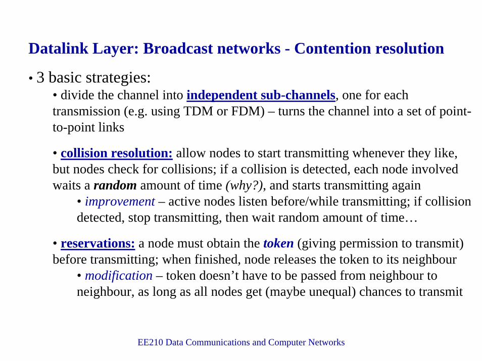
Datalink Layer: Broadcast networks - Contention resolution
• 3 basic strategies:• divide the channel into independent sub-channels, one for each transmission (e.g. using TDM or FDM) – turns the channel into a set of point-to-point links
• collision resolution: allow nodes to start transmitting whenever they like, but nodes check for collisions; if a collision is detected, each node involved waits a random amount of time (why?), and starts transmitting again
• improvement – active nodes listen before/while transmitting; if collision detected, stop transmitting, then wait random amount of time…
• reservations: a node must obtain the token (giving permission to transmit) before transmitting; when finished, node releases the token to its neighbour
• modification – token doesn’t have to be passed from neighbour to neighbour, as long as all nodes get (maybe unequal) chances to transmit
EE210 Data Communications and Computer Networks10
Datalink layer: Broadcast networks – LLC and MAC
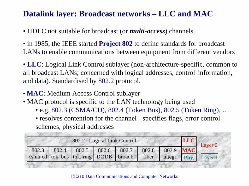
• HDLC not suitable for broadcast (or multi-access) channels
• in 1985, the IEEE started Project 802 to define standards for broadcastLANs to enable communications between equipment from different vendors
• LLC: Logical Link Control sublayer (non-architecture-specific, common toall broadcast LANs; concerned with logical addresses, control information, and data). Standardised by 802.2 protocol.
• MAC: Medium Access Control sublayer• MAC protocol is specific to the LAN technology being used
• e.g. 802.3 (CSMA/CD), 802.4 (Token Bus), 802.5 (Token Ring), …• resolves contention for the channel - specifies flags, error control schemes, physical addresses
802.5tok. ring
802.4tok. bus
802.6DQDB
802.7broadb.
802.8fiber
802.3csma-cd
802.9integr.
MACPhy.
802.2 Logical Link Control LLC
Layer 1
Layer 2

EE210 Data Communications and Computer Networks11
Datalink layer: Broadcast networks – LLC and MAC• data unit at LLC sublayer is called a PDU (Protocol Data Unit)
• PDU has no flag fields, no CRC/checksum, and no physical (machine) addresses - these are supplied by the MAC sublayer
logical addresses
PDU control fieldidentical to HDLC
control field

12
Datalink layer: Broadcast networks – New Standards• Recently, three more standards have been added:
•802.11 is the Wireless LAN standard•802.11a (up to 54 Mbps in the 5 GHz band)•802.11b (up to 11 Mbps in the 2.4 GHz band)•802.11g (up to 54 Mbps in the 2.4 GHz band)•…
•802.16 is the a Wireless Point-to-multipoint standard
•802.15 is a Personal Area Network. This is similar to Bluetooth

EE210 Data Communications and Computer Networks13
Datalink layer: Ethernet• mid-70s: Xerox PARC developed first Ethernet to connect 100 computers on a 1 km cable; subsequently developed by Xerox, DEC, and Intel• Ethernet is slightly different to IEEE 802.3• channel access method: CSMA/CD (Carrier Sense Multiple Access with Collision Detection) - try to reduce the likelihood and effects of a collision
• CSMA: a node wishing to transmit must first listen to the channel (e.g. by measuring the channel’s voltage level). If the channel is busy, some other node is transmitting and our node must wait until it detects that the channel is idle. When the channel is determined to be idle, our node can transmit.
• CD: during transmission, our node listens to the channel and if another transmission is detected (e.g. higher voltage level than expected for one transmission), all nodes involved in the collision stop transmitting immediately. Each node then computes a randomly-sized time interval, waits for that amount of time, and begins the transmission attempt again.
• basic problem with CSMA/CD is that, theoretically, a node wishing to transmit may never be able to (Maximum Medium Access Time-MMAT = ∞): even with random waiting times, the node’s transmission attempts may collide every time

EE210 Data Communications and Computer Networks14
Datalink layer: collisions in CSMA/CD / Ethernet• even with Carrier Sensing before transmission, collisions can still occur because it takes non-zero time for signal to propagate along the channel• if the propagation time along the length of the channel is denoted by τ, can show that the worst-case collision detection time is (approximately) 2τ
• this shows why there is a minimum frame length in CSMA/CD systems: all frames must take more than 2τ to transmit (“pad” information field, if necessary)
noise burst generated by node B to warn all other nodes about collision

EE210 Data Communications and Computer Networks15
Datalink layer: performance of CSMA/CD / Ethernet• main complication is the analysis of the randomisation algorithm each node uses to determine how long it should wait after detecting a collision before attempting to transmit again
• algorithm used is called BEB (Binary Exponential Backoff)• basic idea: the more collisions this transmission attempt has been involved in so far, the longer it may have to wait before attempting again• in heavy traffic conditions, BEB results in an average contention period of w = (2τ) × e seconds, or approximately w = 5.4τ
each “slot” has duration 2τ
heavy traffic assumption ⇒ no idle periods

EE210 Data Communications and Computer Networks16
Datalink layer: performance of CSMA/CD / Ethernet (cont.)• efficiency = (TRANSF) / (TRANSF + w) = 1 / (1 + [w/TRANSF])
• but τ = channel propagation delay = PROP, and w = 5.4τ• therefore efficiency = 1 / (1 + 5.4×[PROP/TRANSF])• therefore throughput = efficiency/TRANSF = 1 / (TRANSF + 5.4×PROP)
• allows us to see the effects on efficiency and throughput when some system characteristic(s) are changed. Examples:
• if length of the channel is increased with everything else held constant:• then PROP increases (since PROP = (length of channel)/(signal propagation speed in channel)), so both efficiency and throughput decrease
• if channel bandwidth is decreased with everything else held constant:• then TRANSF increases (since TRANSF = (length of Frame)/(channel bandwidth), so efficiency increases, but throughput decreases
• Note: efficiency only measures the fraction of time spent doing “useful work”, in this case transmitting Frames – if it takes longer to transmit Frames and the propagation delay is held constant (meaning the collision detection time is held constant), then a larger fraction of the time is spent actually transmitting Frames !

EE210 Data Communications and Computer Networks17
Datalink layer: CSMA/CD / Ethernet Frame
802.2 PDUphysical addresses
Preamble is to allow Receiver to synchronise with incoming transmission.
SFD is the start flag in Ethernet.
Node physical address: 6 bytes, encoded on node’s Network InterfaceCard (NIC). Each NIC ever made has a unique 6-byte address.
Maximum length of Data field = 1500 bytes.
Note: There is no provision for ACK/NAKThis must be implemented at a higher layer ⇒ Ethernet is an unreliable medium

EE210 Data Communications and Computer Networks18
Datalink layer: Ethernet Implementations (1)
10Base5: 10 Mbps, Baseband (digital encoding),maximum channel length = 500 metres
(also called “Thick Ethernet”)

EE210 Data Communications and Computer Networks19
Datalink layer: Ethernet Implementations (2)
10Base2: 10 Mbps, Baseband (digital encoding),maximum channel length = 185 metres
(also called “Thin Ethernet” or “cheapnet”)
transceiver circuitry moved into NIC; no need for AUI cables

EE210 Data Communications and Computer Networks20
Datalink layer: Ethernet Implementations (3)
10BaseT: 10 Mbps, Baseband (digital encoding), twisted pair wiring,maximum length hub-to-node = 100 metres
logically still a bus topology, although physical topology is a star

EE210 Data Communications and Computer Networks21
Datalink layer: Ethernet Implementations (4)
Switched Ethernet: replace hub in 10BaseT with a switch
linecard
typically: 4-32 line cardsconnected by a high-speed
(e.g. 1 Gbps) backplaneinside the switch
10BaseT: when a node sends a Frame to the hub, it is sent out on allother hub interfaces ⇒ only one node can transmit at a time
Switched Ethernet: when a node sends a Frame to the switch, it is sent out only on the destination node interface ⇒ switch can forward more Frames at a time

EE210 Data Communications and Computer Networks22
Datalink layer: Ethernet Implementations (5)
Fast Ethernet: increase channel bandwidth to 100 Mbps
to achieve this 10-fold speedup,the maximum channel length
must be reduced by a factor of 10:2500 metres (with repeaters)
reduced to 250 metres
Gigabit Ethernet: increase channel bandwidth to 1000 Mbps = 1 Gbps• mainly intended for use with optical fibres• maximum channel length reduced to 25 metres• usually for backbone connection between Fast Ethernet networks

EE210 Data Communications and Computer Networks23
Datalink layer: CSMA/CD Advantages & Disadvantages+ low average access time under light loading conditions+ easy to move/upgrade/change nodes, due to distributed channel access protocol+ graceful performance degradation as number of nodes increases+ the most popular LAN technology, with a huge installed base– substantial analogue component: collision detection circuitry– minimum valid frame length is inefficient if data is short (e.g. 1 character)– priorities not supported ⇒ difficult to support (e.g.) real-time traffic– channel access time unpredictable– as load increases: access time increases, and is theoretically unbounded• the potential problems with Ethernet led to the development of some alternative technologies in the early 80s
• IBM chose a ring topology for office automation applications – led to the Token Ring (802.5) standard• General Motors, and others interested in factory automation, chose a bus topology as a good match to layout of assembly lines – led to the Token Bus (802.4) standard
• key point: the Maximum Medium Access Time (MMAT) is bounded, assuming the network is working correctly

EE210 Data Communications and Computer Networks24
Datalink layer: Token Ring networks (802.5)• “ring” is actually a set of point-to-point links that form a circle
• ring is (logically) unidirectional• token = special frame that is passed from one node to the next
• a node may only transmit Frame(s) when it has the token• when a node receives the token, it removes it from the ring and transmits one Frame, then puts the token back on the ring (i.e. transmits it to next node)
• “removing the token” means changing it into the start of a data Frame…
“listen” or“wait” mode
“transmit”mode
while in this 1-bit buffer, a bit can be inspectedand possibly modified before being written out

EE210 Data Communications and Computer Networks25
Datalink layer: Token Ring – token passing1. 2.
3. 4.
Frame now carriesindication that theintended Receiver
copied it

EE210 Data Communications and Computer Networks26
Datalink layer: Token Ring Frame formats
numberof bytes
used to indicate (1) Receiver address recognised,and (2) Frame copied by Receiver

EE210 Data Communications and Computer Networks27
Datalink layer: Token Ring Performance Analysis• assume heavy traffic: all nodes always have Frames to transmit
• a complete cycle consists of each node waiting for the token, transmitting one Frame when they get the token, and then releasing the token• cycle time = N×[TRANSF + TRANST + PROP] + PROP, where
• N = number of nodes• TRANSF = Frame transmission time• TRANST = token transmission time• PROP = ring latency = propagation delay around the ring
• useful time within a cycle = N×TRANSF
• therefore efficiency = (useful time)/(cycle time)
• approximation: if TRANST << TRANSF and N >> 1, then approximately efficiency ≈ 1/(1+a), where a = PROP/TRANSF
• note that if a is negligible (in other words, PROP << TRANSF), then the efficiency is approximately 100%
• can find throughput = efficiency/TRANSF
sum of propagation delays astoken circulates around ring

EE210 Data Communications and Computer Networks28
Datalink layer: Token Ring Performance Analysis (cont.)• what is the worst-case access time for a Frame which is ready for transmission ? (Note: ignore queueing delay within a node)
• MMAT occurs when the node has just started transmitting the last Frame allowed by the token: then newly-ready Frame will have to wait while token circulates around ring, with every node transmitting a Frame
• MMAT = cycle time = N×[TRANSF + TRANST + PROP] + PROP
• so worst-case access time is known and finite• modification permitted in IEEE 802.5 standard: when a node receives the token, it is allowed to transmit for up to THT seconds before releasing the token (THT = Token Holding Time)
• typically THT >> TRANSF, so several Frames may be transmitted every time the token is captured
• efficiency ≈ 1/(1+b), where b = PROP/THT
• MMAT = [TRANSF + TRANST + PROP] + (N-1)×[THT + TRANST + PROP] + PROP, which as before is known and finite

EE210 Data Communications and Computer Networks29
Datalink layer: Token Ring Implementation• problem with ring topology: if there is a break in the cable between 2 nodes, or if a node crashes, the ring is broken• solution: wire centre – if a cable breaks or a node crashes, appropriate relay closes and faulty section of ring is bypassed
802.5 standard specifies:• 4 or 16 Mbps• THT = 10 millisec• priority levels• automatic ring maintenance
(1 node designated as thering monitor; every nodeis capable of doing this)
physical topology is a star,but logical topology is a ring

EE210 Data Communications and Computer Networks30
Datalink layer: Token Bus networks (802.4)• physically a bus, but logically a token-passing ring
• each node in the logical ring knows physical address of its successor and its predecessor• each node connected to the bus (whether it is in the logical ring or not) receives each Frame – but discards Frames not addressed to it
as used incable TV
the physical ordering of nodes on the bus is irrelevant to the operationof the token bus protocol, though it has an impact on performance

EE210 Data Communications and Computer Networks31
Datalink layer: Token Bus Frame Format
Preamble: to synchronise Receiver to incoming signal, as in Ethernet.
Frame Control: indicates data or control Frame; for data Frames, alsoindicates Frame’s priority level. Can also carry indication that Receivermust ACK or NAK the Frame.
Addresses: same as in Ethernet protocol.
802.4 standard specifies:• 1, 5, or 10 Mbps• THT operation (similar to Token Ring)• different physical layer to Ethernet (allows symbols other than 0 or 1)• distributed automatic logical ring maintenance (no centralised monitor)• supports priorities: can be configured to provide a guaranteed fraction
of the bandwidth to highest-priority traffic (e.g. real-time traffic)

EE210 Data Communications and Computer Networks32
Datalink layer: Fibre Distributed Data Interface (FDDI)• standardised by ANSI and ITU-T, originally as a high-speed alternative to Ethernet and Token Ring LANs since FDDI runs at 100 Mbps
• copper-wire version now available: CDDI• access method is token-passing, limited by time
• supports 2 kinds of traffic: real-time and non-real-time• real-time traffic sent first when token received
• now mostly used as a backbone to connect other LANs of various types
a device which can connect2 different networks at the
Datalink layer
can be up to 200 km,with 1000 nodes

EE210 Data Communications and Computer Networks33
Datalink layer: FDDI (cont.)• FDDI implemented as a dual ring
• usually, all transmissions on primary ring; other (secondary) ring used only for backup when some part of the primary ring fails
normaloperation
ringfailure
difference from TokenRing: in FDDI, node
releases tokenimmediately after
Frame transmission
• Frame format similarto IEEE 802.5:
number of bytes

EE210 Data Communications and Computer Networks34
Data Link Layer: Wireless LANs
Wireless LAN’s are relatively recentAdvantages
Relatively little infrastructure is requiredUsers can move around (laptops)
DisadvantagesEquipment still quite expensiveSecurityErrors will be more frequentLower Bit Rates

EE210 Data Communications and Computer Networks35
Data Link Layer: Wireless LANsWhat MAC is appropriate for Wireless LAN
Try CSMAInterference at the Sender is not the same as the receiverDifficult to listen and transmitC cannot hear A, but will ruin A->B Frame
Beware ‘Hidden’ and ‘Exposed’ Station ProblemsHidden Station:
A is transmitting to BC senses medium, and concludes it can transmitThis wipes out frame at A
Exposed StationB is transmitting to AC cannot transmit as medium is busyBut in reality, it could transmit to D
A B C D

EE210 Data Communications and Computer Networks36
Data Link Layer: Wireless LANs
Multiple Access with Collision AvoidanceWorks with a CTS, RTS scheme
BAC D
E
RTSCTS
Range of B
Range of A

EE210 Data Communications and Computer Networks37
Data Link Layer: Wireless LANs
A wishes to transmit to BC, B and E hear the RTS from AA, E and D hear the CTS from BA starts to transmitD knows not to, even though it cannot hear AActually, C can transmit, as B will not hear it. Must only wait for CTS
Collisions can occur between RTS frames, but not as seriousMACAW (MACA for Wireless adds Acknowledgements)CSMA is used to reduce RTS collisions

EE210 Data Communications and Computer Networks38
Data Link Layer: Wireless LANs
802.11Infrared
802.11FHSS
802.11DSSS
802.11aOFDM
802.11bHR-DSSS
802.11gOFDM
Logical Link Control
Upper Layers
MAC sublayer