4th Generation HIL.
10
www.typhoon-hil.com HIL404. Deploy HIL in a day. It is the only way. 4 th Generation HIL.
Transcript of 4th Generation HIL.

www.typhoon-hil.com
HIL404.Deploy HIL in a day. It is the only way.
4th Generation HIL.
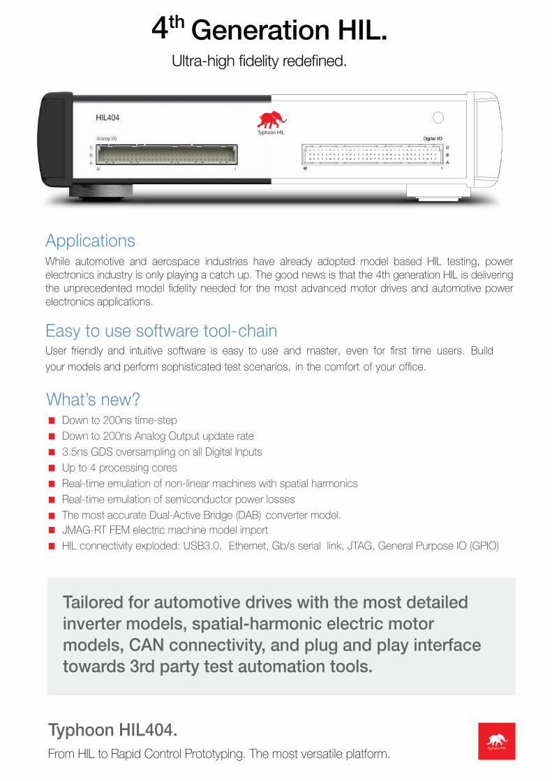
Generation HIL.Ultra-high fidelity redefined.
4th
ApplicationsWhile automotive and aerospace industries have already adopted model based HIL testing, power electronics industry is only playing a catch up. The good news is that the 4th generation HIL is delivering the unprecedented model fidelity needed for the most advanced motor drives and automotive power electronics applications.
Easy to use software tool-chain
What’s new?< Down to 200ns time-step<
3.5ns GDS oversampling on all Digital Inputs< Up to 4 processing cores<
< < <
<
User friendly and intuitive software is easy to use and master, even for first time users. Build
your models and perform sophisticated test scenarios, in the comfort of your office.
Down to 200ns Analog Output update rate<
Real-time emulation of non-linear machines with spatial harmonicsReal-time emulation of semiconductor power lossesThe most accurate Dual-Active Bridge (DAB) converter model.JMAG-RT FEM electric machine model importHIL connectivity exploded: USB3.0, Ethernet, Gb/s serial link, JTAG, General Purpose IO (GPIO)
Tailored for automotive drives with the most detailed inverter models, spatial-harmonic electric motor models, CAN connectivity, and plug and play interface towards 3rd party test automation tools.
Typhoon HIL404.From HIL to Rapid Control Prototyping. The most versatile platform.
sony
Line
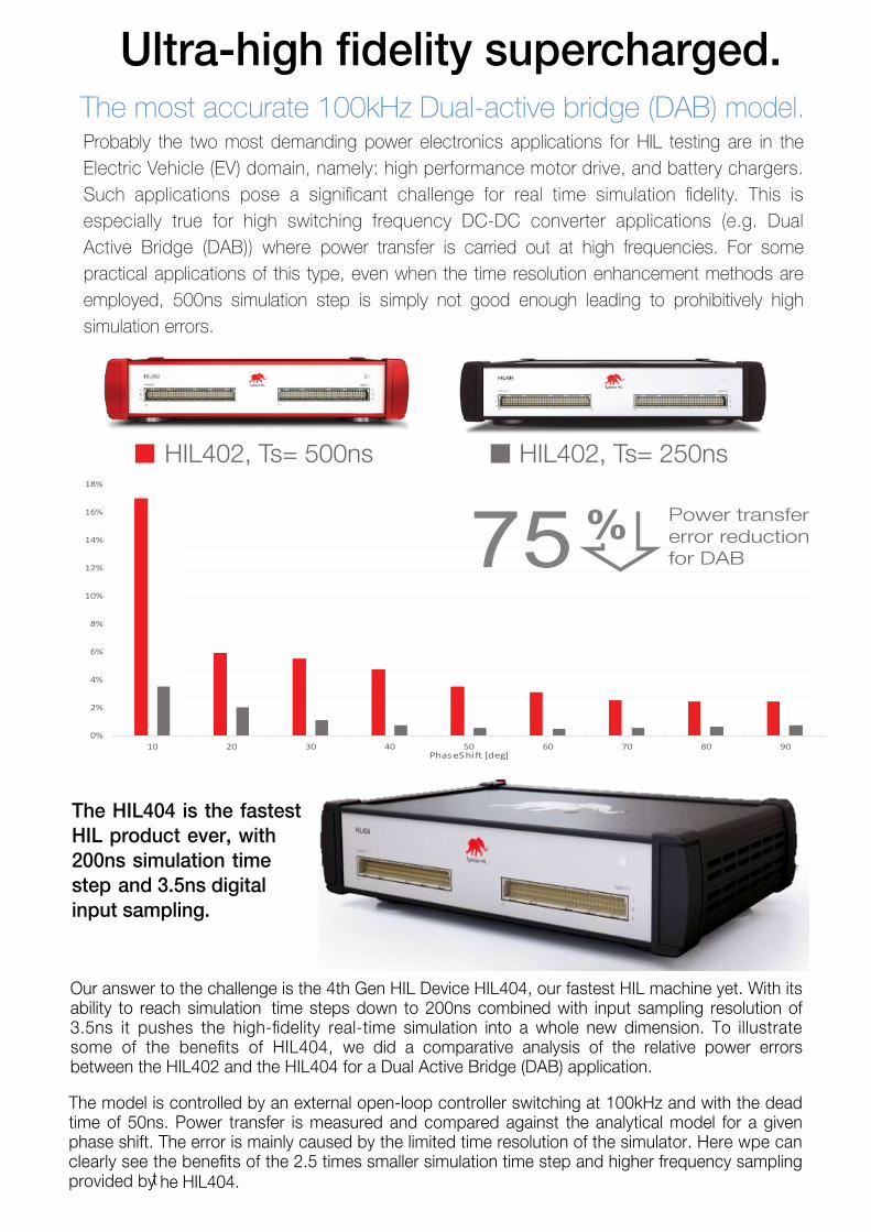
Ultra-high fidelity supercharged.The most accurate 100kHz Dual-active bridge (DAB) model.Probably the two most demanding power electronics applications for HIL testing are in the Electric Vehicle (EV) domain, namely: high performance motor drive, and battery chargers. Such applications pose a significant challenge for real time simulation fidelity. This is especially true for high switching frequency DC-DC converter applications (e.g. Dual Active Bridge (DAB)) where power transfer is carried out at high frequencies. For some practical applications of this type, even when the time resolution enhancement methods are employed, 500ns simulation step is simply not good enough leading to prohibitively high simulation errors.
HIL402, Ts= 500ns HIL402, Ts= 250ns
the HIL404.0%
2%
4%
6%
8%
10%
12%
14%
16%
18%
10 20 30 40 50 60 70 80 90PhaseShi [deg]
75 % Power transfererror reductionfor DAB
Our answer to the challenge is the 4th Gen HIL Device HIL404, our fastest HIL machine yet. With its ability to reach simulation time steps down to 200ns combined with input sampling resolution of 3.5ns it pushes the high-fidelity real-time simulation into a whole new dimension. To illustrate some of the benefits of HIL404, we did a comparative analysis of the relative power errors between the HIL402 and the HIL404 for a Dual Active Bridge (DAB) application.
The model is controlled by an external open-loop controller switching at 100kHz and with the dead time of 50ns. Power transfer is measured and compared against the analytical model for a given phase shift. The error is mainly caused by the limited time resolution of the simulator. Here wpe can clearly see the benefits of the 2.5 times smaller simulation time step and higher frequency sampling provided by t he HIL404.
The HIL404 is the fastest HIL product ever, with 200ns simulation time step and 3.5ns digital input sampling.
<
<
<
Pow
er
ID s
el
SFP
2x
JTAG
CAN
2x
SD c
ard
UART
2x
GPI
O
ETH
2x
USB
3.0
Controler Under Test
Typhoon HIL Control Center (Software Toolchain) Typhoon HIL404 (Hardware in Loop unit)
JMAG Finite ElementM odeling Software
Switchingd evicel oss data
Matlab & Simulink Code Generation
Controller
Battery Inverter Electrical Motors Drivetrain Load
+
HIL404
gate drive signals
current/voltage signals
position sensor signals
real-time motor drive model
direct export of controler code
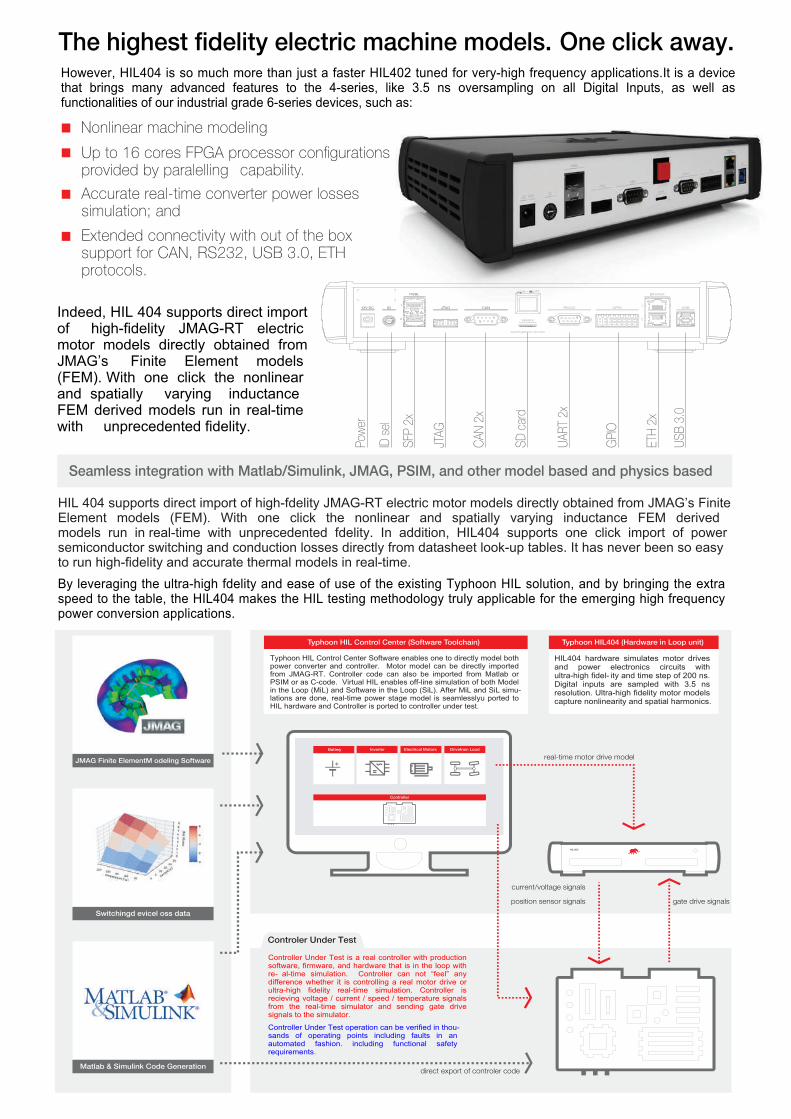
The highest fidelity electric machine models. One click away.
Up to 16 cores FPGA processor configurations provided by paralelling capability.
Accurate real-time converter power losses simulation; and
Extended connectivity with out of the box support for CAN, RS232, USB 3.0, ETH protocols.
Seamless integration with Matlab/Simulink, JMAG, PSIM, and other model based and physics based
Typhoon HIL Control Center Software enables one to directly model both power converter and controller. Motor model can be directly imported from JMAG-RT. Controller code can also be imported from Matlab or PSIM or as C-code. Virtual HIL enables off-line simulation of both Model in the Loop (MiL) and Software in the Loop (SiL). After MiL and SiL simu-lations are done, real-time power stage model is seamlesslyu ported to HIL hardware and Controller is ported to controller under test.
HIL404 hardware simulates motor drives and power electronics circuits with ultra-high fidel- ity and time step of 200 ns. Digital inputs are sampled with 3.5 ns resolution. Ultra-high fidelity motor models capture nonlinearity and spatial harmonics.
Controller Under Test is a real controller with production software, firmware, and hardware that is in the loop with re- al-time simulation. Controller can not “feel” any difference whether it is controlling a real motor drive or ultra-high fidelity real-time simulation. Controller is recieving voltage / current / speed / temperature signals from the real-time simulator and sending gate drive signals to the simulator.
Controller Under Test operation can be verified in thou-sands of operating points including faults in an automated fashion. including functional safety requirements.
However, HIL404 is so much more than just a faster HIL402 tuned for very-high frequency applications.It is a device that brings many advanced features to the 4-series, like 3.5 ns oversampling on all Digital Inputs, as well as functionalities of our industrial grade 6-series devices, such as:
Nonlinear machine modeling
<
Indeed, HIL 404 supports direct importof high-fidelity JMAG-RT electric motor models directly obtained fromJMAG’s Finite Element models (FEM). With one click the nonlinear and spatially varying inductance FEM derived models run in real-time with unprecedented fidelity.
HIL 404 supports direct import of high-fdelity JMAG-RT electric motor models directly obtained from JMAG’s FiniteElement models (FEM). With one click the nonlinear and spatially varying inductance FEM derived models run in real-time with unprecedented fdelity. In addition, HIL404 supports one click import of power semiconductor switching and conduction losses directly from datasheet look-up tables. It has never been so easy to run high-fidelity and accurate thermal models in real-time.By leveraging the ultra-high fdelity and ease of use of the existing Typhoon HIL solution, and by bringing the extra speed to the table, the HIL404 makes the HIL testing methodology truly applicable for the emerging high frequency power conversion applications.
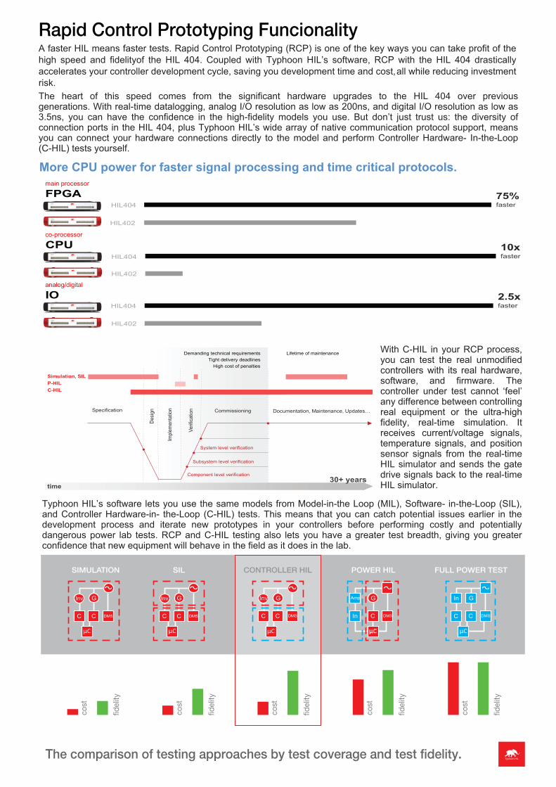
More CPU power for faster signal processing and time critical protocols.
FPGA
CPU
IO
75%faster
10xfaster
2.5xfaster
HIL404
HIL404
HIL404
HIL402
HIL402
HIL402
main processor
co-processor
analog/digital
System level verification
Component level verification
Subsystem level verification
Specification
Desig
n
Impl
emen
tatio
n
Verif
icatio
n Commissioning Documentation, Maintenance, Updates…
Simulation, SILP-HILC-HIL
Lifetime of maintenance
time30+ years
Demanding technical requirementsTight delivery deadlines
High cost of penalties
Rapid Control Prototyping FuncionalityA faster HIL means faster tests. Rapid Control Prototyping (RCP) is one of the key ways you can take profit of the high speed and fidelityof the HIL 404. Coupled with Typhoon HIL’s software, RCP with the HIL 404 drastically accelerates your controller development cycle, saving you development time and cost,all while reducing investment risk.The heart of this speed comes from the significant hardware upgrades to the HIL 404 over previous generations. With real-time datalogging, analog I/O resolution as low as 200ns, and digital I/O resolution as low as 3.5ns, you can have the confidence in the high-fidelity models you use. But don’t just trust us: the diversity of connection ports in the HIL 404, plus Typhoon HIL’s wide array of native communication protocol support, means you can connect your hardware connections directly to the model and perform Controller Hardware- In-the-Loop (C-HIL) tests yourself.
With C-HIL in your RCP process, you can test the real unmodified controllers with its real hardware, software, and firmware. The controller under test cannot ‘feel’ any difference between controlling real equipment or the ultra-high fidelity, real-time simulation. It receives current/voltage signals, temperature signals, and position sensor signals from the real-time HIL simulator and sends the gate drive signals back to the real-time HIL simulator.
Typhoon HIL’s software lets you use the same models from Model-in-the Loop (MIL), Software- in-the-Loop (SIL), and Controller Hardware-in- the-Loop (C-HIL) tests. This means that you can catch potential issues earlier in the development process and iterate new prototypes in your controllers before performing costly and potentially dangerous power lab tests. RCP and C-HIL testing also lets you have a greater test breadth, giving you greater confidence that new equipment will behave in the field as it does in the lab.
The comparison of testing approaches by test coverage and test fidelity.
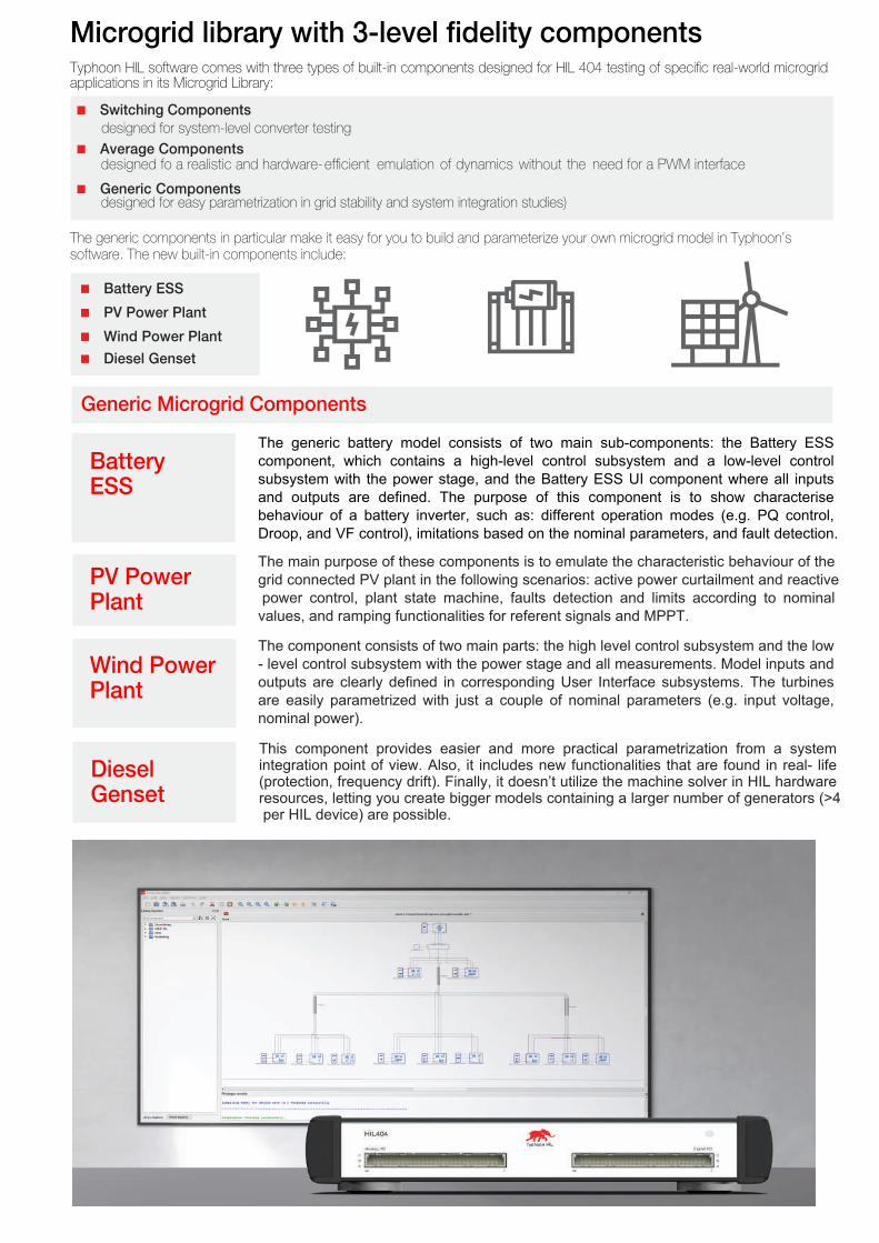
Microgrid library with 3-level fidelity components
< Generic Components
< Average Components
< Switching Components designed for system-level converter testing
Typhoon HIL software comes with three types of built-in components designed for HIL 404 testing of specific real-world microgrid applications in its Microgrid Library:
designed for easy parametrization in grid stability and system integration studies)
designed fo a realistic and hardware-efficient emulation of dynamics without the need for a PWM interface
The generic components in particular make it easy for you to build and parameterize your own microgrid model in Typhoon’s software. The new built-in components include:
< Battery ESS
< PV Power Plant
< Wind Power Plant
< Diesel Genset
Generic Microgrid Components
Battery ESS
The generic battery model consists of two main sub-components: the Battery ESS component, which contains a high-level control subsystem and a low-level control subsystem with the power stage, and the Battery ESS UI component where all inputs and outputs are defined. The purpose of this component is to show characterise behaviour of a battery inverter, such as: different operation modes (e.g. PQ control, Droop, and VF control), imitations based on the nominal parameters, and fault detection. The main purpose of these components is to emulate the characteristic behaviour of the grid connected PV plant in the following scenarios: active power curtailment and reactive power control, plant state machine, faults detection and limits according to nominal values, and ramping functionalities for referent signals and MPPT.
PV Power Plant
The component consists of two main parts: the high level control subsystem and the low - level control subsystem with the power stage and all measurements. Model inputs and outputs are clearly defined in corresponding User Interface subsystems. The turbines are easily parametrized with just a couple of nominal parameters (e.g. input voltage, nominal power).
Wind Power Plant
This component provides easier and more practical parametrization from a system integration point of view. Also, it includes new functionalities that are found in real- life (protection, frequency drift). Finally, it doesn’t utilize the machine solver in HIL hardware resources, letting you create bigger models containing a larger number of generators (>4 per HIL device) are possible.
Diesel Genset
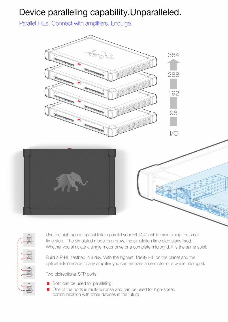
I/O
384
288
192
96
Two bidirectional SFP ports :
< Both can be used for paralleling < One of the ports is multi-purpose and can be used for high-speed
communication with other devices in the future
Build a P-HIL testbed in a day. With the highest fidelity HIL on the planet and the optical link interface to any amplifier you can emulate an e-motor or a whole microgrid.
Device paralleling capability.Unparalleled.Parallel HILs. Connect with amplifiers. Endulge.
Use the high speed optical link to parallel your HIL404’s while maintaining the small time step. The simulated model can grow, the simulation time step stays fixed. Whether you simulate a single motor drive or a complete microgrid, it is the same spiel.
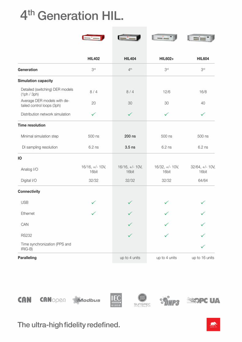
4th Generation HIL.
HIL402 HIL404 HIL602+ HIL604
Generation 3rd 4th 3rd 3rd
Simulation capacity
Detailed (switching) DER models (1ph / 3ph)
8 / 4 8 / 4 12/6 16/8
Average DER models with de-tailed control loops (3ph)
20 30 30 40
Distribution network simulation
Time resolution
Minimal simulation step 500 ns 200 ns 500 ns 500 ns
DI sampling resolution 6.2 ns 3.5 ns 6.2 ns 6.2 ns
IO
Analog I/O16/16, +/- 10V,
16bit16/16, +/- 10V,
16bit16/32, +/- 10V,
16bit32/64, +/- 10V,
16bit
Digital I/O 32/32 32/32 32/32 64/64
Connectivity
USB
Ethernet
CAN
RS232
Time synchronization (PPS and IRIG-B)
Paralleling up to 4 units up to 4 units up to 16 units
The ultra-high fidelity redefined.
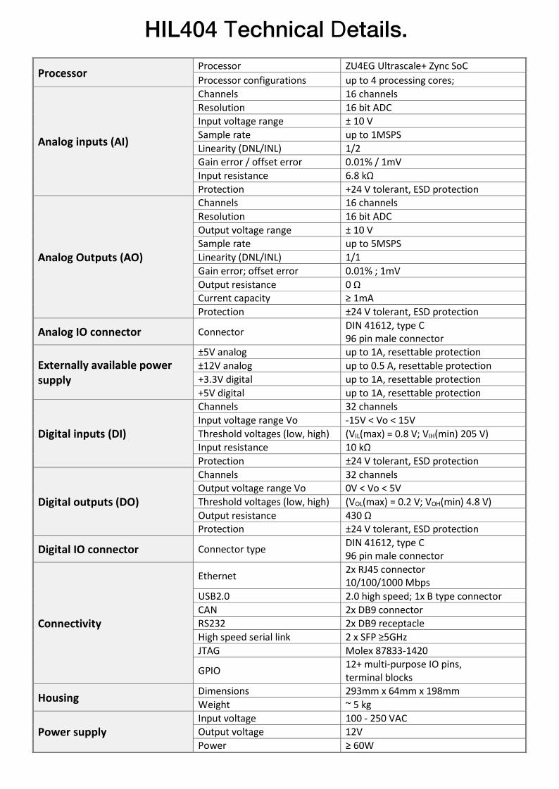
HIL404 Technical Details.
Processor Processor ZU4EG Ultrascale+ Zync SoC
Processor configurations up to 4 processing cores;
Analog inputs (AI)
Channels 16 channels
Resolution 16 bit ADC Input voltage range ± 10 V
Sample rate up to 1MSPS
Linearity (DNL/INL) 1/2 Gain error / offset error 0.01% / 1mV
Input resistance 6.8 kΩ
Protection +24 V tolerant, ESD protection
Analog Outputs (AO)
Channels 16 channels
Resolution 16 bit ADC
Output voltage range ± 10 V Sample rate up to 5MSPS
Linearity (DNL/INL) 1/1
Gain error; offset error 0.01% ; 1mV
Output resistance 0 Ω Current capacity ≥ 1mA
Protection ±24 V tolerant, ESD protection
Analog IO connector Connector DIN 41612, type C 96 pin male connector
Externally available power supply
±5V analog up to 1A, resettable protection
±12V analog up to 0.5 A, resettable protection
+3.3V digital up to 1A, resettable protection
+5V digital up to 1A, resettable protection
Digital inputs (DI)
Channels 32 channels
Input voltage range Vo -15V < Vo < 15V
Threshold voltages (low, high) (VIL(max) = 0.8 V; VIH(min) 205 V) Input resistance 10 kΩ
Protection ±24 V tolerant, ESD protection
Digital outputs (DO)
Channels 32 channels Output voltage range Vo 0V < Vo < 5V
Threshold voltages (low, high) (VOL(max) = 0.2 V; VOH(min) 4.8 V)
Output resistance 430 Ω Protection ±24 V tolerant, ESD protection
Digital IO connector Connector type DIN 41612, type C 96 pin male connector
Connectivity
Ethernet 2x RJ45 connector 10/100/1000 Mbps
USB2.0 2.0 high speed; 1x B type connector
CAN 2x DB9 connector RS232 2x DB9 receptacle
High speed serial link 2 x SFP ≥5GHz
JTAG Molex 87833-1420
GPIO 12+ multi-purpose IO pins, terminal blocks
Housing Dimensions 293mm x 64mm x 198mm
Weight ~ 5 kg
Power supply Input voltage 100 - 250 VAC Output voltage 12V
Power ≥ 60W
Typhoon HIL, Inc.15 Ward Street, 2nd Floor
Somerville, MA 02143USA
Typhoon HIL GmbHTechnoparkstrasse 1
CH-8005 ZürichSwitzerland
Tajfun HIL d.o.o.Bajci Zilinskog bb
21000 Novi SadRepublic of Serbia
Phone: +1 800-766-3181 Phone: +1 800-766-3181 Phone: +381 21 3010 476
www.typhoon-hil.come-mail: [email protected]
Typhoon HIL's Indian Partner
QUARBZ INFO SYSTEMS 2nd Floor, Skylark Complex, 14/147, Chunniganj, Kanpur – 208 001
Email: [email protected] * Website : www.quarbz.com Contact Nos.: 91-983807 1684 / 85