
48 V 12 V 25 A 300 W 2000 V dc Quarter-brick
14
Product # BQ50120QTx25 Phone 1-888-567-9596 www.synqor.com Doc.# 005-2BQ512M Rev. H 05/16/19 Page 1 Technical Specification BQ50120QTx25 Contents ® Operational Features • High efficiency, 96.1% at full rated load current • Delivers up to 25 A (300 Watts) of output current (power) with minimal derating - no heat sink required • Operating input voltage range: 42-53 V • Fixed frequency switching provides predictable EMI performance • No minimum load requirement Protection Features • Input under-voltage lockout and over-voltage shutdown protect against abnormal input voltages • Output current limit and short circuit protection (auto recovery) • Thermal shutdown BQ50120QTx25 Model Mechanical Features • Industry standard quarter-brick pin-out configuration • Size: 1.45” x 2.3” (36.8 x 58.4 mm), height: 0.467” (11.86 mm) • Total open frame weight: 1.5 oz (42 g) The BusQor® BQ50120QTx25 bus converter is a next- generation, board-mountable, isolated, fixed switching frequency DC-DC converter that uses synchronous rectification to achieve extremely high conversion efficiency. The power dissipated by the converter is so low that a heat sink is not required, which saves cost, weight, height, and application effort. The BusQor series provides an isolated step down voltage from 48V to 12V intermediate bus with no regulation in a standard quarter-brick module. BusQor converters are ideal for creating the mid-bus voltage required to drive point-of-load (non-isolated) converters in intermediate bus architectures. Safety Features • CAN/CSA C22.2 No. 60950-1 • UL 60950-1 • EN 60950-1 Control Features • On/Off control referenced to input side (positive and negative logic options are available) • Current sharing allowed without the use of any external circuitry. 48 V 12 V 25 A 300 W 2000 V dc Quarter-brick Input Output Current Power Isolation DC-DC Converter Open Frame Mechanical Diagram ............................ 2 Baseplated Mechanical Diagram ............................. 3 Electrical Characteristics ................................... 4 Compliance & Testing .................................... 6 Technical Figures........................................ 7 Applications Section ..................................... 10 Ordering Information .................................... 14
Transcript of 48 V 12 V 25 A 300 W 2000 V dc Quarter-brick
Product # BQ50120QTx25 Phone 1-888-567-9596 www.synqor.com Doc.# 005-2BQ512M Rev. H 05/16/19 Page 1
Technical Specification
BQ50120QTx25
Contents
®
Operational Features• High efficiency, 96.1% at full rated load current• Delivers up to 25 A (300 Watts) of output current (power) with minimal derating - no heat sink required• Operating input voltage range: 42-53 V• Fixed frequency switching provides predictable EMI performance• No minimum load requirement
Protection Features• Input under-voltage lockout and over-voltage shutdown protect against abnormal input voltages• Output current limit and short circuit protection (auto recovery)• Thermal shutdown
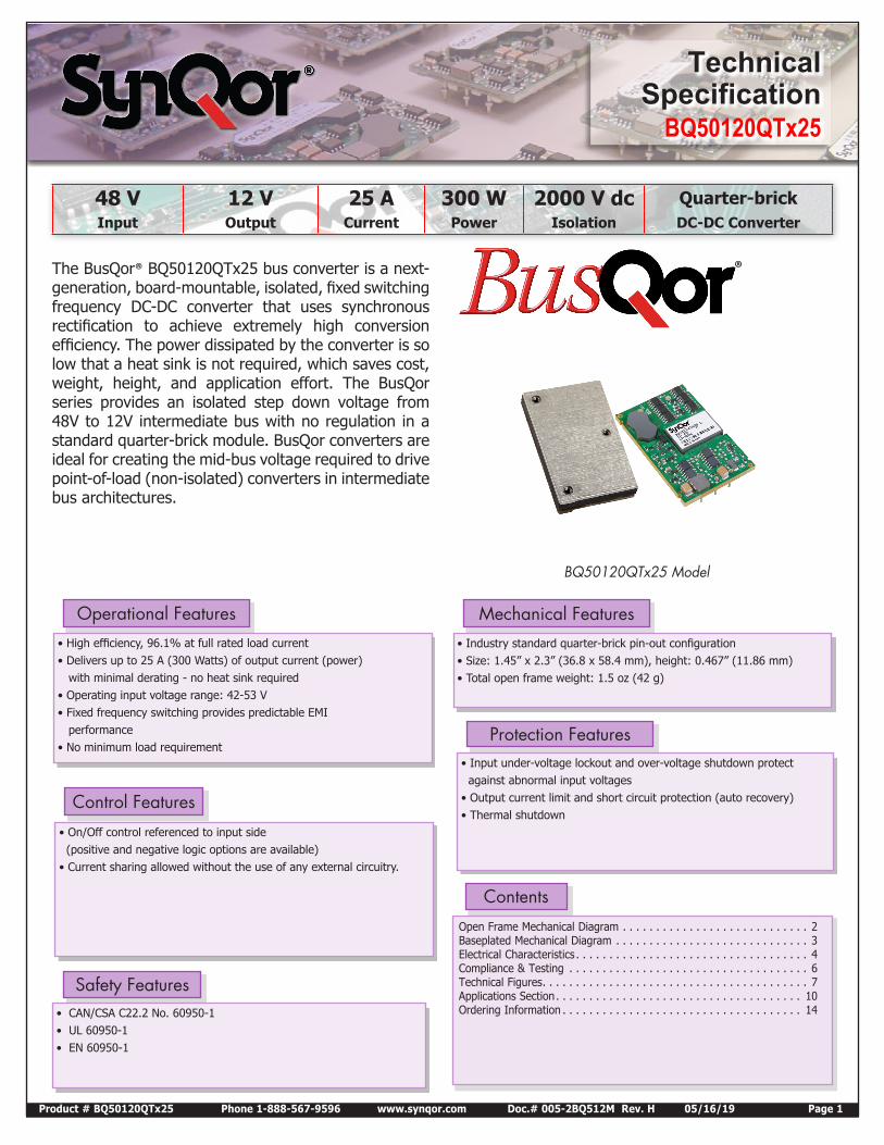
BQ50120QTx25 Model
Mechanical Features• Industry standard quarter-brick pin-out configuration• Size: 1.45” x 2.3” (36.8 x 58.4 mm), height: 0.467” (11.86 mm)• Total open frame weight: 1.5 oz (42 g)
The BusQor® BQ50120QTx25 bus converter is a next-generation, board-mountable, isolated, fixed switching frequency DC-DC converter that uses synchronous rectification to achieve extremely high conversion efficiency. The power dissipated by the converter is so low that a heat sink is not required, which saves cost, weight, height, and application effort. The BusQor series provides an isolated step down voltage from 48V to 12V intermediate bus with no regulation in a standard quarter-brick module. BusQor converters are ideal for creating the mid-bus voltage required to drive point-of-load (non-isolated) converters in intermediate bus architectures.
Safety Features• CAN/CSA C22.2 No. 60950-1• UL 60950-1• EN 60950-1
Control Features
• On/Off control referenced to input side (positive and negative logic options are available)• Current sharing allowed without the use of any external circuitry.
48 V 12 V 25 A 300 W 2000 V dc Quarter-brickInput Output Current Power Isolation DC-DC Converter
Open Frame Mechanical Diagram . . . . . . . . . . . . . . . . . . . . . . . . . . . . 2Baseplated Mechanical Diagram . . . . . . . . . . . . . . . . . . . . . . . . . . . . . 3Electrical Characteristics . . . . . . . . . . . . . . . . . . . . . . . . . . . . . . . . . . . 4Compliance & Testing . . . . . . . . . . . . . . . . . . . . . . . . . . . . . . . . . . . . 6Technical Figures. . . . . . . . . . . . . . . . . . . . . . . . . . . . . . . . . . . . . . . . 7Applications Section. . . . . . . . . . . . . . . . . . . . . . . . . . . . . . . . . . . . . 10Ordering Information . . . . . . . . . . . . . . . . . . . . . . . . . . . . . . . . . . . . 14
Product # BQ50120QTx25 Phone 1-888-567-9596 www.synqor.com Doc.#005-2BQ512M Rev. H 05/16/19 Page 2
Input: 42-53 V Output: 12 V Current: 25 A Package: Quarter-brick
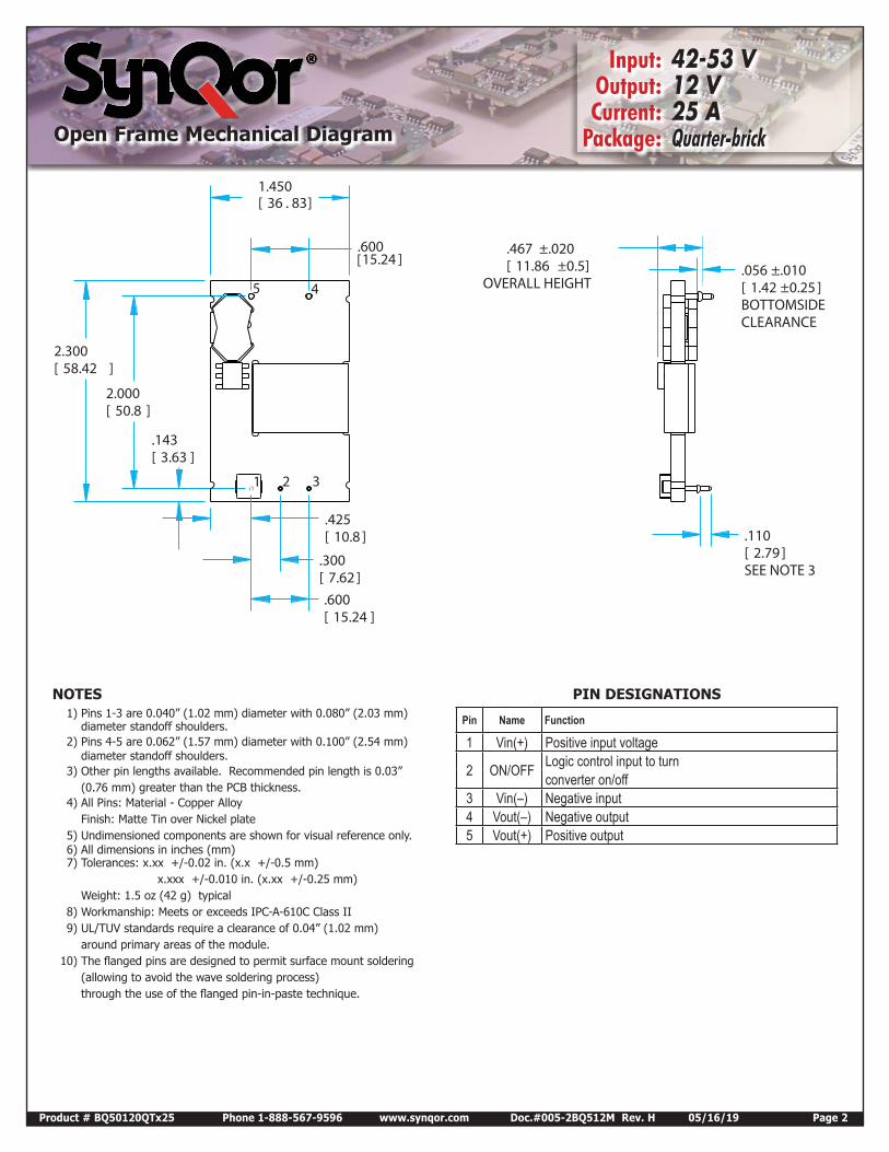
1.450[ 36.83]
2.300[ 58.42 ]
.467 ±.020[ 11.86 ±0.5]
OVERALL HEIGHT
.110[ 2.79 ]SEE NOTE 3
.600[15.24 ]
2.000[ 50.8 ]
.425[ 10.8 ]
.143[ 3.63 ]
.300[ 7.62 ].600[ 15.24 ]
.056 ±.010[ 1.42 ±0.25 ]BOTTOMSIDECLEARANCE
1 2 3
45
NOTES1) Pins 1-3 are 0.040” (1.02 mm) diameter with 0.080” (2.03 mm)
diameter standoff shoulders.2) Pins 4-5 are 0.062” (1.57 mm) diameter with 0.100” (2.54 mm)
diameter standoff shoulders.3) Other pin lengths available. Recommended pin length is 0.03”
(0.76 mm) greater than the PCB thickness.4) All Pins: Material - Copper Alloy
Finish: Matte Tin over Nickel plate5) Undimensioned components are shown for visual reference only.6) All dimensions in inches (mm)7) Tolerances: x.xx +/-0.02 in. (x.x +/-0.5 mm)
x.xxx +/-0.010 in. (x.xx +/-0.25 mm) Weight: 1.5 oz (42 g) typical
8) Workmanship: Meets or exceeds IPC-A-610C Class II9) UL/TUV standards require a clearance of 0.04” (1.02 mm)
around primary areas of the module. 10) The flanged pins are designed to permit surface mount soldering
(allowing to avoid the wave soldering process) through the use of the flanged pin-in-paste technique.
PIN DESIGNATIONS
Pin Name Function
1 Vin(+) Positive input voltage
2 ON/OFF Logic control input to turn converter on/off
3 Vin(–) Negative input4 Vout(–) Negative output5 Vout(+) Positive output
Open Frame Mechanical Diagram
Product # BQ50120QTx25 Phone 1-888-567-9596 www.synqor.com Doc.#005-2BQ512M Rev. H 05/16/19 Page 3
Input: 42-53 V Output: 12 V Current: 25 A Package: Quarter-brick
PIN DESIGNATIONS
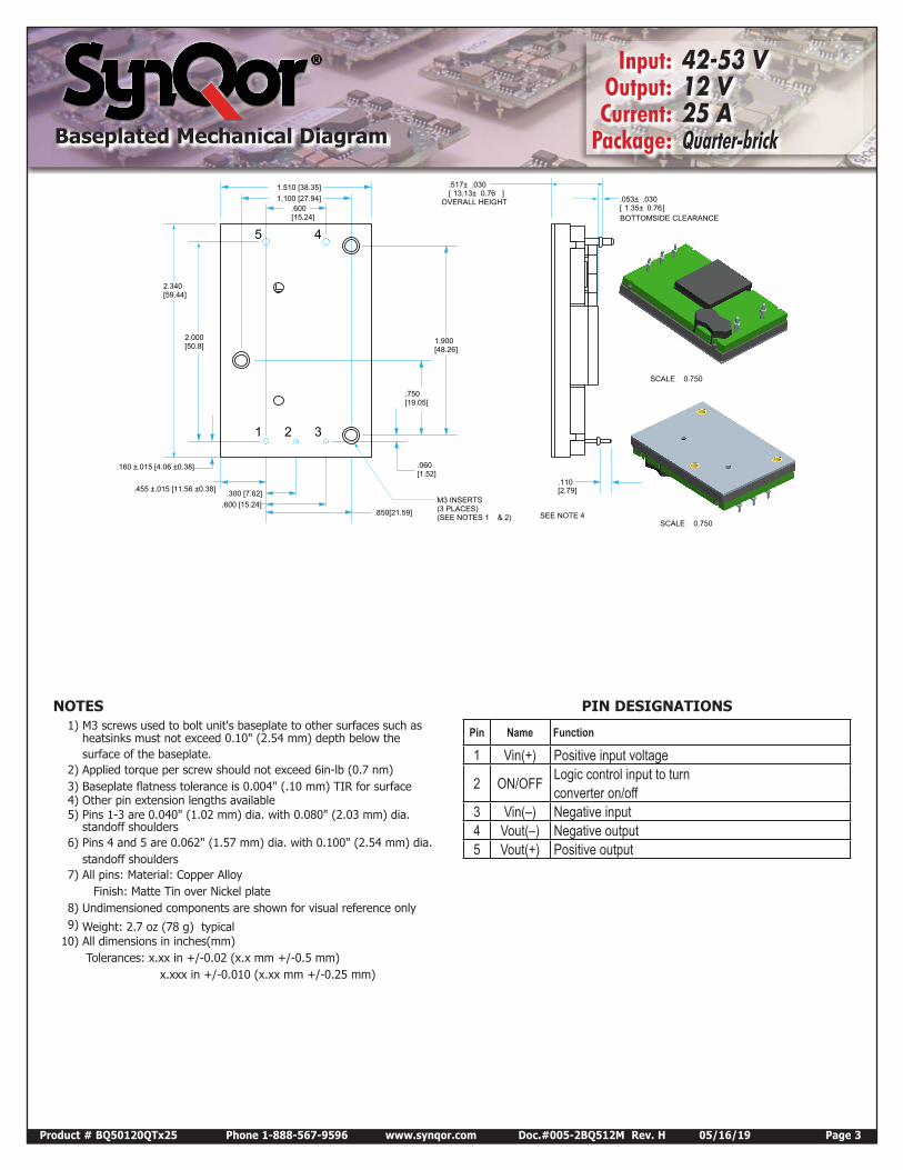
Pin Name Function
1 Vin(+) Positive input voltage
2 ON/OFF Logic control input to turn converter on/off
3 Vin(–) Negative input4 Vout(–) Negative output5 Vout(+) Positive output
0.750SCALE
0.750SCALE
2.000[50.8]
.300 [7.62].600 [15.24]
.160 ±.015 [4.06 ±0.38]
.455 ±.015 [11.56 ±0.38]
.600[15.24]
2.340[59.44]
1.510 [38.35]
OVERALL HEIGHT
.517± .03013.13± 0.76[ ]
BOTTOMSIDE CLEARANCE
.053± .0301.35± 0.76[ ]
.110[2.79]
SEE NOTE 4
M3 INSERTS(3 PLACES)(SEE NOTES 1 & 2)
1.900[48.26]
.060[1.52]
.750[19.05]
1.100 [27.94]
.850[21.59]
1 2 3
45
NOTES1) M3 screws used to bolt unit's baseplate to other surfaces such as
heatsinks must not exceed 0.10" (2.54 mm) depth below the surface of the baseplate.
2) Applied torque per screw should not exceed 6in-lb (0.7 nm)3) Baseplate flatness tolerance is 0.004" (.10 mm) TIR for surface4) Other pin extension lengths available5) Pins 1-3 are 0.040" (1.02 mm) dia. with 0.080" (2.03 mm) dia.
standoff shoulders6) Pins 4 and 5 are 0.062" (1.57 mm) dia. with 0.100" (2.54 mm) dia.
standoff shoulders7) All pins: Material: Copper Alloy
Finish: Matte Tin over Nickel plate8) Undimensioned components are shown for visual reference only9) Weight: 2.7 oz (78 g) typical
10) All dimensions in inches(mm) Tolerances: x.xx in +/-0.02 (x.x mm +/-0.5 mm) x.xxx in +/-0.010 (x.xx mm +/-0.25 mm)
Baseplated Mechanical Diagram
Product # BQ50120QTx25 Phone 1-888-567-9596 www.synqor.com Doc.# 005-2BQ512M Rev. H 05/16/19 Page 4
Technical Specification
Input: 42-53 V Output: 12 V Current: 25 A Package: Quarter-brick
Electrical Characteristics
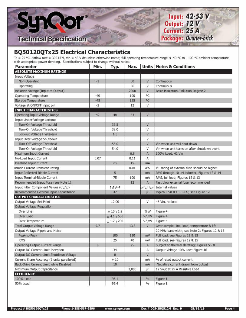
BQ50120QTx25 Electrical CharacteristicsTa = 25 °C, airflow rate = 300 LFM, Vin = 48 V dc unless otherwise noted; full operating temperature range is -40 °C to +100 °C ambient temperature with appropriate power derating. Specifications subject to change without notice.
Parameter Min. Typ. Max. Units Notes & Conditions ABSOLUTE MAXIMUM RATINGS Input Voltage
Non-Operating -1 60 V Continuous Operating 56 V Continuous
Isolation Voltage (Input to Output) 2000 V Basic insulation, Pollution Degree 2 Operating Temperature -40 100 °C Storage Temperature -45 125 °C Voltage at ON/OFF input pin -2 12 V INPUT CHARACTERISTICS Operating Input Voltage Range 42 48 53 V Input Under-Voltage Lockout
Turn-On Voltage Threshold 39.5 V Turn-Off Voltage Threshold 38.0 V Lockout Voltage Hysteresis 1.5 V
Input Over-Voltage Shutdown V Turn-Off Voltage Threshold 55.0 V Vin when unit will shut down Turn-On Voltage Threshold 54.0 V Vin when unit turns on after shutdown event
Maximum Input Current 6.8 A 100% Load, 42 Vin No-Load Input Current 0.07 0.11 A Disabled Input Current 7.5 15 mA Inrush Current Transient Rating 0.01 A2S I2T rating of external fuse should be higher Input Reflected-Ripple Current 5 mA RMS through 10 µH inductor; Figures 12 & 14 Input Terminal-Ripple Current 75 100 mA RMS, full load; Figures 12 & 13 Recommended Input Fuse (see Note 1) 12 A Fast blow external fuse recommended Input Filter Component Values (C\L\C) 1\1\4.4 µF\µH\µF Internal values Recommended External input Capacitance 47 µF Typical ESR 0.1 - .02 Ω, see Figure 12 OUTPUT CHARACTERISTICS Output Voltage Set Point 12.00 V 48 Vin, no load Output Voltage Regulation
Over Line + 10 \ 1.2 %\V Figure 4 Over Load + 4.1 \ 500 %\mV Figure 4 Over Temperature + 1.7 \ 200 %\mV Figure 4
Total Output Voltage Range 9.7 13.3 V Over sample, line, load, temperature & life Output Voltage Ripple and Noise 20 MHz bandwidth; see Note 2; Figures 12 & 15
Peak-to-Peak 100 150 mV Full load, see Figures 12 & 15 RMS 25 40 mV Full load, see Figures 12 & 15
Operating Output Current Range 0 25 A Subject to thermal derating; Figures 5 - 8 Output DC Current-Limit Inception 34 A Output Voltage 10% Low; Figure 16 Output DC Current-Limit Shutdown Voltage 8 V Current Share Accuracy (2 units paralleled) + 10 mA % of rated output current Back-Drive Current Limit while Disabled 10 mA Negative current drawn from output Maximum Output Capacitance 3,000 µF 12 Vout at 25 A Resistive Load EFFICIENCY 100% Load 96.1 % Figure 1 50% Load 96.4 % Figure 1
Product # BQ50120QTx25 Phone 1-888-567-9596 www.synqor.com Doc.# 005-2BQ512M Rev. H 05/16/19 Page 5
Technical Specification
Input: 42-53 V Output: 12 V Current: 25 A Package: Quarter-brick
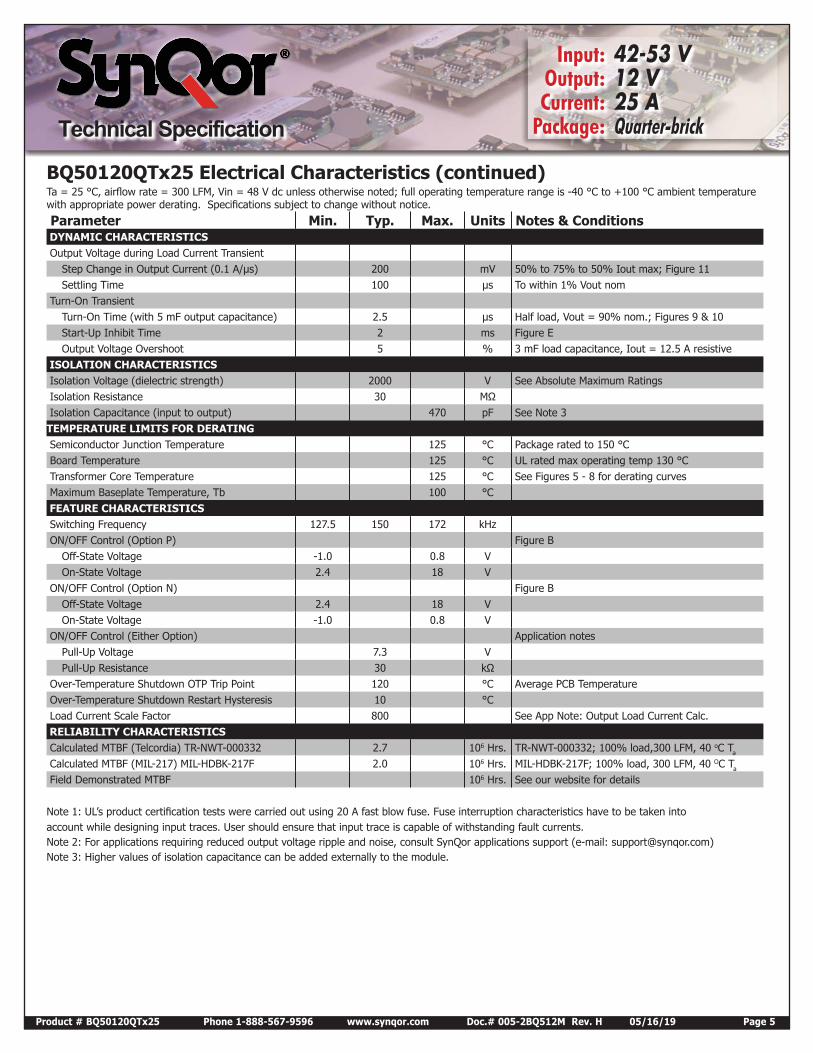
BQ50120QTx25 Electrical Characteristics (continued)Ta = 25 °C, airflow rate = 300 LFM, Vin = 48 V dc unless otherwise noted; full operating temperature range is -40 °C to +100 °C ambient temperature with appropriate power derating. Specifications subject to change without notice.
Parameter Min. Typ. Max. Units Notes & Conditions DYNAMIC CHARACTERISTICS Output Voltage during Load Current Transient
Step Change in Output Current (0.1 A/µs) 200 mV 50% to 75% to 50% Iout max; Figure 11 Settling Time 100 µs To within 1% Vout nom
Turn-On Transient Turn-On Time (with 5 mF output capacitance) 2.5 µs Half load, Vout = 90% nom.; Figures 9 & 10 Start-Up Inhibit Time 2 ms Figure E Output Voltage Overshoot 5 % 3 mF load capacitance, Iout = 12.5 A resistive
ISOLATION CHARACTERISTICS Isolation Voltage (dielectric strength) 2000 V See Absolute Maximum Ratings Isolation Resistance 30 MΩ Isolation Capacitance (input to output) 470 pF See Note 3TEMPERATURE LIMITS FOR DERATING Semiconductor Junction Temperature 125 °C Package rated to 150 °C Board Temperature 125 °C UL rated max operating temp 130 °C Transformer Core Temperature 125 °C See Figures 5 - 8 for derating curves Maximum Baseplate Temperature, Tb 100 °C FEATURE CHARACTERISTICS Switching Frequency 127.5 150 172 kHz ON/OFF Control (Option P) Figure B
Off-State Voltage -1.0 0.8 V On-State Voltage 2.4 18 V
ON/OFF Control (Option N) Figure B Off-State Voltage 2.4 18 V On-State Voltage -1.0 0.8 V
ON/OFF Control (Either Option) Application notes Pull-Up Voltage 7.3 V Pull-Up Resistance 30 kΩ
Over-Temperature Shutdown OTP Trip Point 120 °C Average PCB Temperature Over-Temperature Shutdown Restart Hysteresis 10 °C Load Current Scale Factor 800 See App Note: Output Load Current Calc. RELIABILITY CHARACTERISTICS Calculated MTBF (Telcordia) TR-NWT-000332 2.7 106 Hrs. TR-NWT-000332; 100% load,300 LFM, 40 oC Ta
Calculated MTBF (MIL-217) MIL-HDBK-217F 2.0 106 Hrs. MIL-HDBK-217F; 100% load, 300 LFM, 40 OC Ta
Field Demonstrated MTBF 106 Hrs. See our website for details
Note 1: UL’s product certification tests were carried out using 20 A fast blow fuse. Fuse interruption characteristics have to be taken intoaccount while designing input traces. User should ensure that input trace is capable of withstanding fault currents.Note 2: For applications requiring reduced output voltage ripple and noise, consult SynQor applications support (e-mail: [email protected])Note 3: Higher values of isolation capacitance can be added externally to the module.
Product # BQ50120QTx25 Phone 1-888-567-9596 www.synqor.com Doc.# 005-2BQ512M Rev. H 05/16/19 Page 6
Technical Specification
Input: 42-53 V Output: 12 V Current: 25 A Package: Quarter-brick
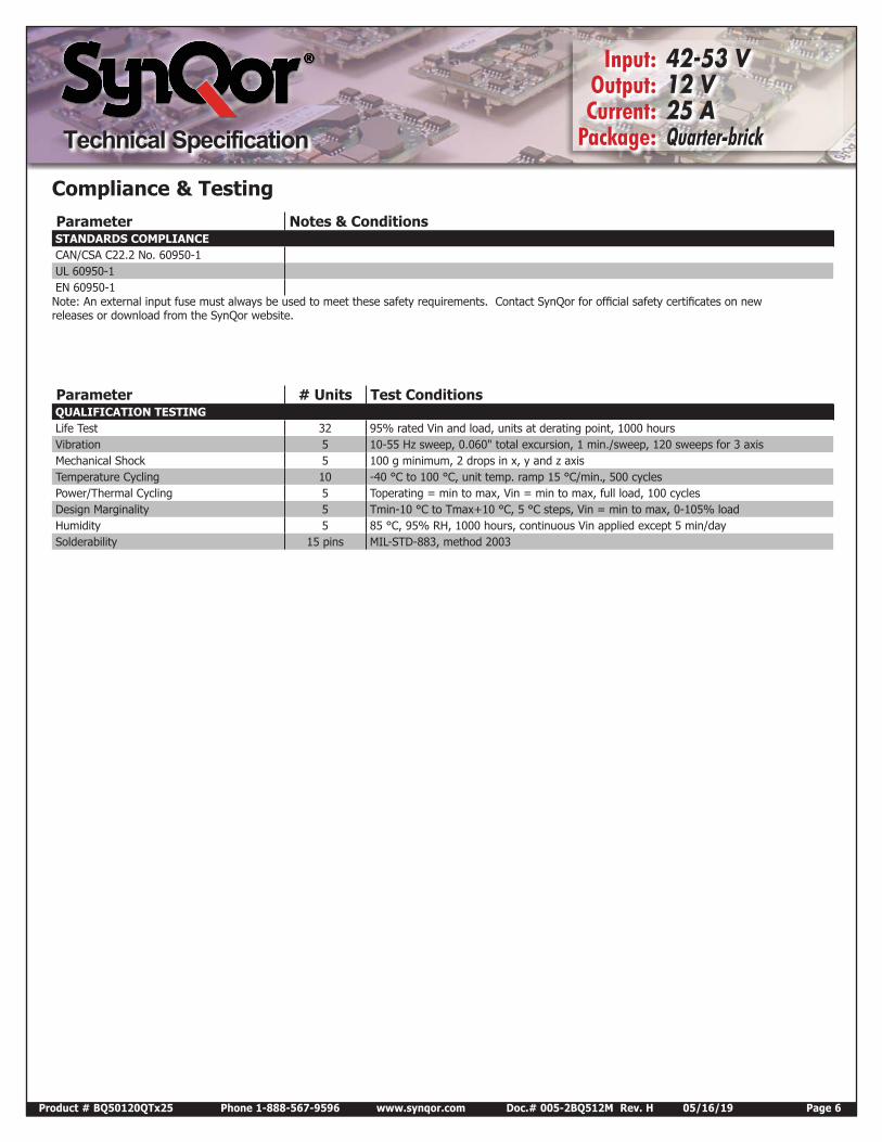
Parameter Notes & Conditions STANDARDS COMPLIANCE CAN/CSA C22.2 No. 60950-1 UL 60950-1 EN 60950-1Note: An external input fuse must always be used to meet these safety requirements. Contact SynQor for official safety certificates on new releases or download from the SynQor website.
Parameter # Units Test Conditions QUALIFICATION TESTING Life Test 32 95% rated Vin and load, units at derating point, 1000 hours Vibration 5 10-55 Hz sweep, 0.060" total excursion, 1 min./sweep, 120 sweeps for 3 axis Mechanical Shock 5 100 g minimum, 2 drops in x, y and z axis Temperature Cycling 10 -40 °C to 100 °C, unit temp. ramp 15 °C/min., 500 cycles Power/Thermal Cycling 5 Toperating = min to max, Vin = min to max, full load, 100 cycles Design Marginality 5 Tmin-10 °C to Tmax+10 °C, 5 °C steps, Vin = min to max, 0-105% load Humidity 5 85 °C, 95% RH, 1000 hours, continuous Vin applied except 5 min/day Solderability 15 pins MIL-STD-883, method 2003
Compliance & Testing
Product # BQ50120QTx25 Phone 1-888-567-9596 www.synqor.com Doc.#005-2BQ512M Rev. H 05/16/19 Page 7
Input: 42-53 V Output: 12 V Current: 25 A Package: Quarter-brick
Semiconductor junction temperature is within 1°C of surface temperature
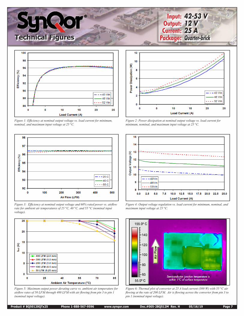
Figure 1: Efficiency at nominal output voltage vs. load current for minimum, nominal, and maximum input voltage at 25 °C.
Figure 2: Power dissipation at nominal output voltage vs. load current for minimum, nominal, and maximum input voltage at 25 °C.
Figure 3: Efficiency at nominal output voltage and 60% rated power vs. airflow rate for ambient air temperatures of 25 °C, 40 °C, and 55 °C (nominal input voltage).
Figure 4: Output voltage regulation vs. load current for minimum, nominal, and maximum input voltage at 25 °C.
Figure 5: Maximum output power derating curve vs. ambient air temperature for airflow rates of 50 LFM through 400 LFM with air flowing from pin 3 to pin 1 (nominal input voltage).
Figure 6: Thermal plot of converter at 25 A load current (300 W) with 55 °C air flowing at the rate of 200 LFM. Air is flowing across the converter from pin 3 to pin 1 (nominal input voltage).
Technical Figures
Technical Figures
Input: 42-53 V Output: 12 V Current: 25 A Package: Quarter-brick
Product # BQ50120QTx25 Phone 1-888-567-9596 www.synqor.com Doc.#005-2BQ512M Rev. H 05/16/19 Page 8
Input: 42-53 V Output: 12 V Current: 25 A Package: Quarter-brick
DC-DCConverter
Input TerminalRipple Current
Output VoltageRipple
Input ReflectedRipple Current
VSOURCE
VOUTiS iC
electrolytic capacitor
ceramiccapacitor
electrolyticcapacitor
sourceimpedance
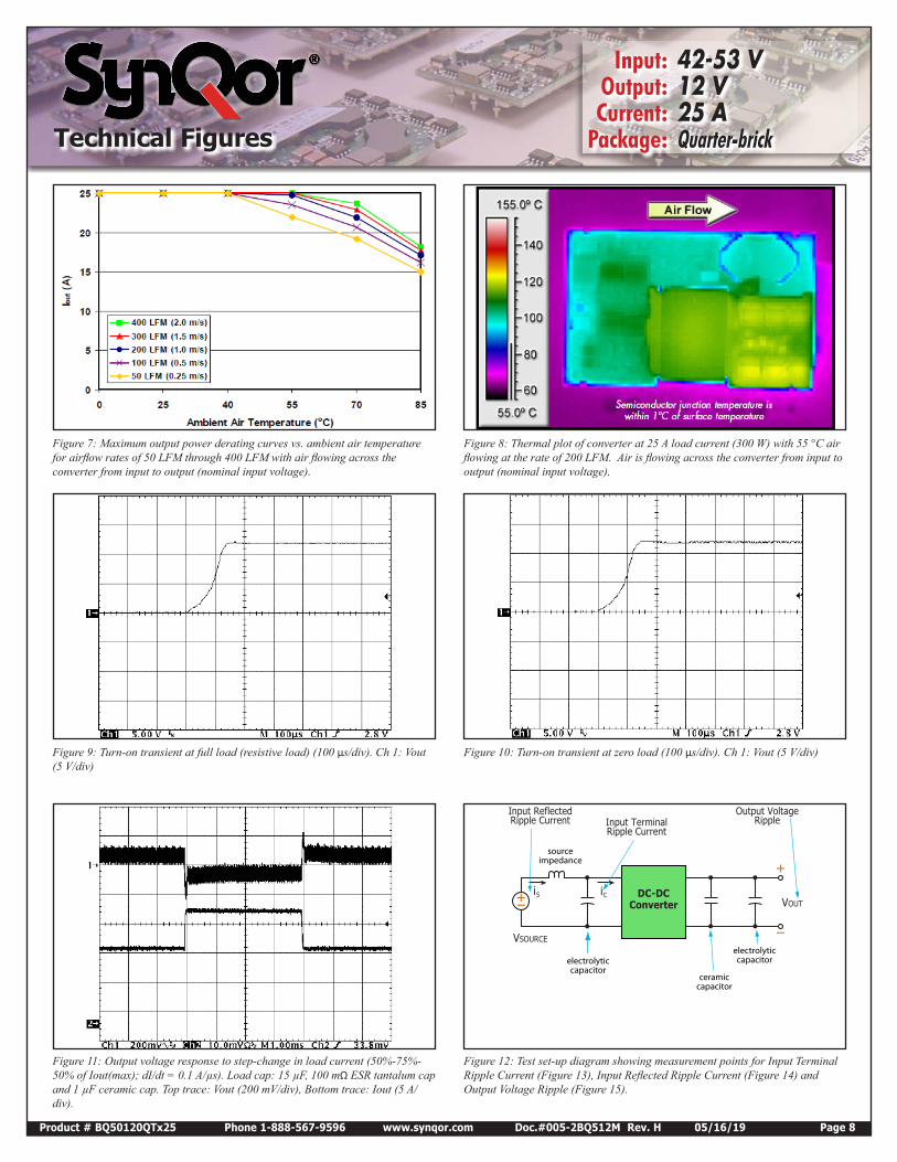
Figure 7: Maximum output power derating curves vs. ambient air temperature for airflow rates of 50 LFM through 400 LFM with air flowing across the converter from input to output (nominal input voltage).
Figure 8: Thermal plot of converter at 25 A load current (300 W) with 55 °C air flowing at the rate of 200 LFM. Air is flowing across the converter from input to output (nominal input voltage).
Figure 9: Turn-on transient at full load (resistive load) (100 μs/div). Ch 1: Vout (5 V/div)
Figure 10: Turn-on transient at zero load (100 μs/div). Ch 1: Vout (5 V/div)
Figure 11: Output voltage response to step-change in load current (50%-75%-50% of Iout(max); dI/dt = 0.1 A/µs). Load cap: 15 µF, 100 mΩ ESR tantalum cap and 1 µF ceramic cap. Top trace: Vout (200 mV/div), Bottom trace: Iout (5 A/div).
Figure 12: Test set-up diagram showing measurement points for Input Terminal Ripple Current (Figure 13), Input Reflected Ripple Current (Figure 14) and Output Voltage Ripple (Figure 15).
Technical Figures
Input: 42-53 V Output: 12 V Current: 25 A Package: Quarter-brick
Input: 42-53 V Output: 12 V Current: 25 A Package: Quarter-brick
Product # BQ50120QTx25 Phone 1-888-567-9596 www.synqor.com Doc.#005-2BQ512M Rev. H 05/16/19 Page 9
Input: 42-53 V Output: 12 V Current: 25 A Package: Quarter-brick
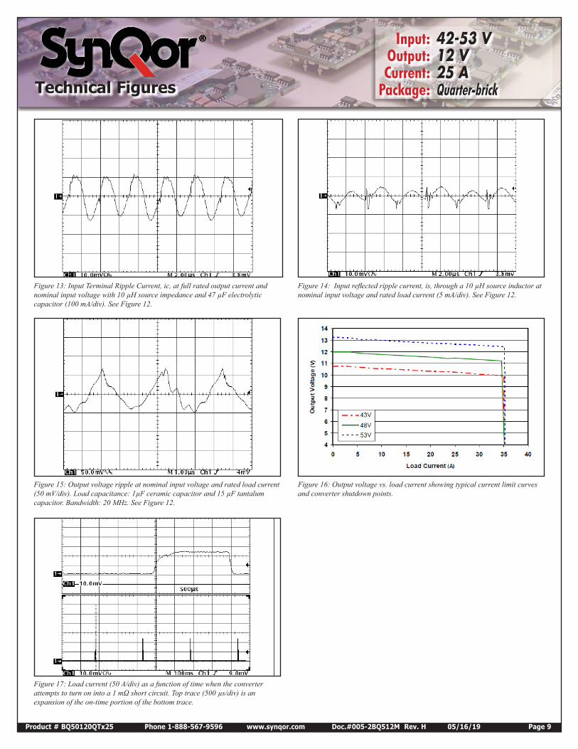
Figure 13: Input Terminal Ripple Current, ic, at full rated output current and nominal input voltage with 10 µH source impedance and 47 µF electrolytic capacitor (100 mA/div). See Figure 12.
Figure 14: Input reflected ripple current, is, through a 10 µH source inductor at nominal input voltage and rated load current (5 mA/div). See Figure 12.
Figure 15: Output voltage ripple at nominal input voltage and rated load current (50 mV/div). Load capacitance: 1µF ceramic capacitor and 15 µF tantalum capacitor. Bandwidth: 20 MHz. See Figure 12.
Figure 16: Output voltage vs. load current showing typical current limit curves and converter shutdown points.
Figure 17: Load current (50 A/div) as a function of time when the converter attempts to turn on into a 1 mΩ short circuit. Top trace (500 µs/div) is an expansion of the on-time portion of the bottom trace.
Technical Figures
Product # BQ50120QTx25 Phone 1-888-567-9596 www.synqor.com Doc.#005-2BQ512M Rev. H 05/16/19 Page 10
Input: 42-53 V Output: 12 V Current: 25 A Package: Quarter-brick
Applications Section
Applications Section
BASIC OPERATION AND FEATURESWith voltages dropping and currents rising, the economics of an Intermediate Bus Architecture (IBA) are becoming more attractive, especially in systems requiring multiple low voltages. IBA systems separate the role of isolation and voltage scaling from regulation and sensing. The BusQor series bus converter provides isolation and an unregulated voltage step down in one compact module, leaving regulation to simpler, less expensive non-isolated converters.
In Figure A below, the BusQor module provides the isolation stage of the IBA system. The isolated bus then distributes power to the non-isolated buck regulators to generate the required voltage levels at the points of load. In this case, the bucks are represented with SynQor’s NiQor series of non-isolated DC/DC converters. In many applications requiring multiple low voltage outputs, significant savings can be achieved in board space and overall system costs
When designing an IBA system with bus converters, the designer can select from a variety of bus voltages. While there is no universally ideal bus voltage, most designs employ one of the following: 12 V, 9 V, 7.5 V, 5 V, or 3.3 V. Higher bus voltages can lead to lower efficiency for the buck regulators but are more efficient for the bus converter and provide lower board level distribution current. Lower bus voltages offer the opposite trade offs.
SynQor’s 12 Vout BusQor module acts as a true dc transformer. The output voltage is proportional to the input voltage, with a specified “turns ratio” or voltage ratio, plus minor drop from the internal resistive losses in the module. When used in IBA systems, the output variation of the BusQor must be in accordance with the input voltage range of the non-isolated converters being employed.
The BusQor architecture is very scalable, meaning multiple bus converters can be connected directly in parallel to allow current sharing for higher power applications.
CONTROL FEATURES
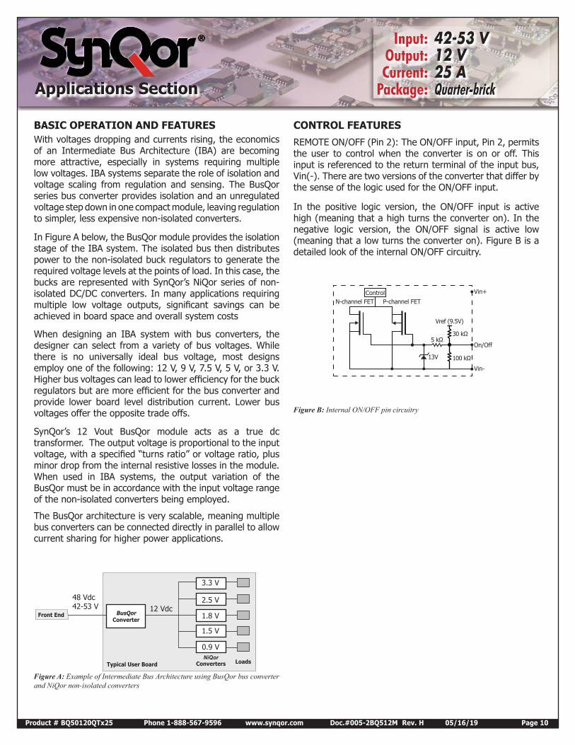
REMOTE ON/OFF (Pin 2): The ON/OFF input, Pin 2, permits the user to control when the converter is on or off. This input is referenced to the return terminal of the input bus, Vin(-). There are two versions of the converter that differ by the sense of the logic used for the ON/OFF input.
In the positive logic version, the ON/OFF input is active high (meaning that a high turns the converter on). In the negative logic version, the ON/OFF signal is active low (meaning that a low turns the converter on). Figure B is a detailed look of the internal ON/OFF circuitry.
BusQorConverter
NiQorConverters Loads
Front End
Typical User Board
Vin+
Vref (9.5V)
5 kΩ30 kΩ
100 kΩ13V
ControlN-channel FET P-channel FET
Vin-
On/Off
Figure A: Example of Intermediate Bus Architecture using BusQor bus converter and NiQor non-isolated converters
48 Vdc 42-53 V 12 Vdc
3.3 V
2.5 V
1.8 V
1.5 V
0.9 V
Figure B: Internal ON/OFF pin circuitry
Input: 42-53 V Output: 12 V Current: 25 A Package: Quarter-brick
Product # BQ50120QTx25 Phone 1-888-567-9596 www.synqor.com Doc.#005-2BQ512M Rev. H 05/16/19 Page 11
Input: 42-53 V Output: 12 V Current: 25 A Package: Quarter-brickApplications Section
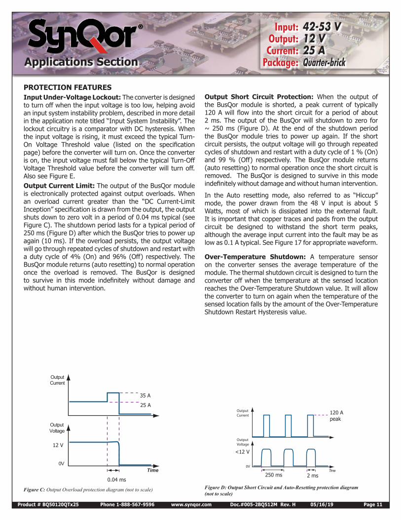
PROTECTION FEATURESInput Under-Voltage Lockout: The converter is designed to turn off when the input voltage is too low, helping avoid an input system instability problem, described in more detail in the application note titled “Input System Instability”. The lockout circuitry is a comparator with DC hysteresis. When the input voltage is rising, it must exceed the typical Turn-On Voltage Threshold value (listed on the specification page) before the converter will turn on. Once the converter is on, the input voltage must fall below the typical Turn-Off Voltage Threshold value before the converter will turn off. Also see Figure E.Output Current Limit: The output of the BusQor module is electronically protected against output overloads. When an overload current greater than the “DC Current-Limit Inception” specification is drawn from the output, the output shuts down to zero volt in a period of 0.04 ms typical (see Figure C). The shutdown period lasts for a typical period of 250 ms (Figure D) after which the BusQor tries to power up again (10 ms). If the overload persists, the output voltage will go through repeated cycles of shutdown and restart with a duty cycle of 4% (On) and 96% (Off) respectively. The BusQor module returns (auto resetting) to normal operation once the overload is removed. The BusQor is designed to survive in this mode indefinitely without damage and without human intervention.
Output Short Circuit Protection: When the output of the BusQor module is shorted, a peak current of typically 120 A will flow into the short circuit for a period of about 2 ms. The output of the BusQor will shutdown to zero for ~ 250 ms (Figure D). At the end of the shutdown period the BusQor module tries to power up again. If the short circuit persists, the output voltage will go through repeated cycles of shutdown and restart with a duty cycle of 1 % (On) and 99 % (Off) respectively. The BusQor module returns (auto resetting) to normal operation once the short circuit is removed. The BusQor is designed to survive in this mode indefinitely without damage and without human intervention.
In the Auto resetting mode, also referred to as “Hiccup” mode, the power drawn from the 48 V input is about 5 Watts, most of which is dissipated into the external fault. It is important that copper traces and pads from the output circuit be designed to withstand the short term peaks, although the average input current into the fault may be as low as 0.1 A typical. See Figure 17 for appropriate waveform.
Over-Temperature Shutdown: A temperature sensor on the converter senses the average temperature of the module. The thermal shutdown circuit is designed to turn the converter off when the temperature at the sensed location reaches the Over-Temperature Shutdown value. It will allow the converter to turn on again when the temperature of the sensed location falls by the amount of the Over-Temperature Shutdown Restart Hysteresis value.
Output Current
Output Voltage
0V Time Time
OutputCurrent
OutputVoltage
0V
Figure C: Output Overload protection diagram (not to scale)
Output Current
35 A
25 A
12 V
0.04 msFigure D: Output Short Circuit and Auto-Resetting protection diagram (not to scale)
120 A peak
<12 V
250 ms 2 ms
Input: 42-53 V Output: 12 V Current: 25 A Package: Quarter-brick
Input: 42-53 V Output: 12 V Current: 25 A Package: Quarter-brick
Product # BQ50120QTx25 Phone 1-888-567-9596 www.synqor.com Doc.#005-2BQ512M Rev. H 05/16/19 Page 12
Input: 42-53 V Output: 12 V Current: 25 A Package: Quarter-brickApplications Section
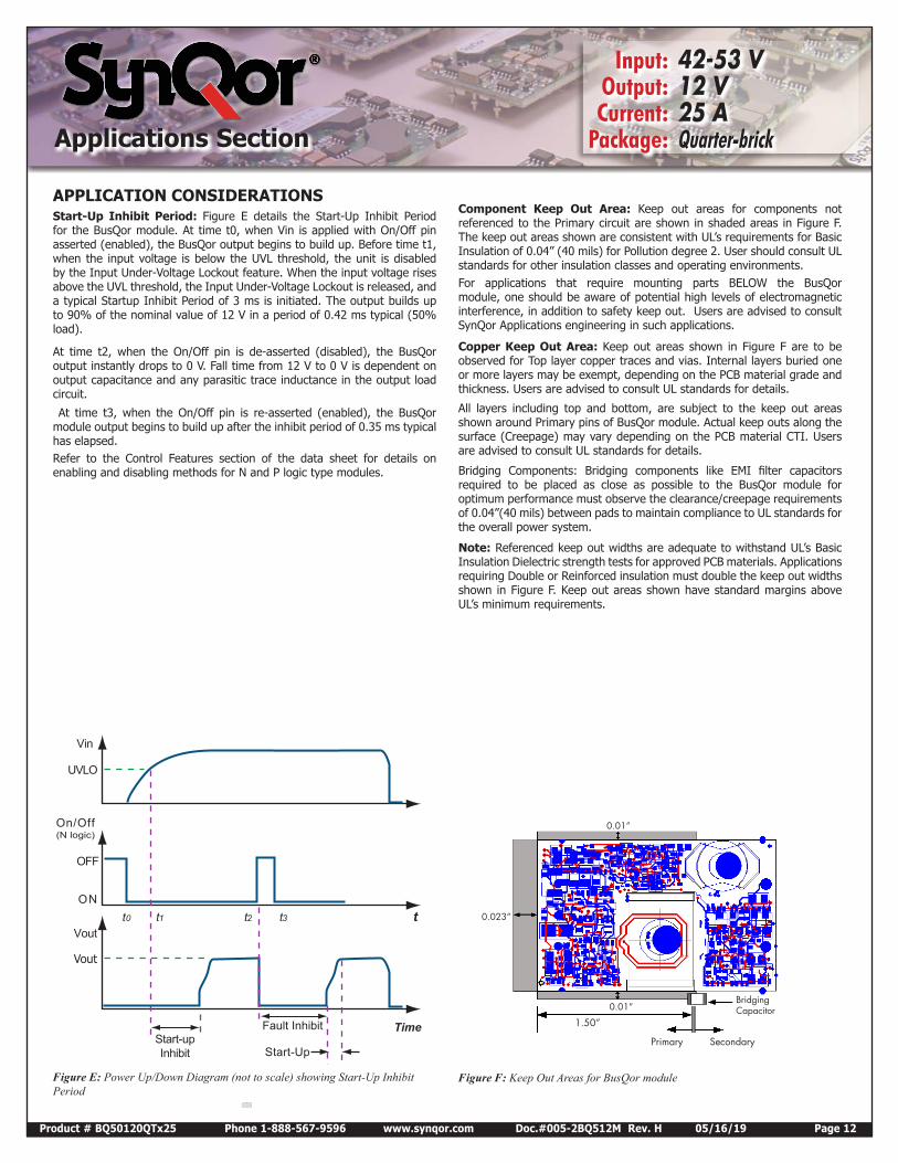
Component Keep Out Area: Keep out areas for components not referenced to the Primary circuit are shown in shaded areas in Figure F. The keep out areas shown are consistent with UL’s requirements for Basic Insulation of 0.04” (40 mils) for Pollution degree 2. User should consult UL standards for other insulation classes and operating environments. For applications that require mounting parts BELOW the BusQor module, one should be aware of potential high levels of electromagnetic interference, in addition to safety keep out. Users are advised to consult SynQor Applications engineering in such applications.
Copper Keep Out Area: Keep out areas shown in Figure F are to be observed for Top layer copper traces and vias. Internal layers buried one or more layers may be exempt, depending on the PCB material grade and thickness. Users are advised to consult UL standards for details.
All layers including top and bottom, are subject to the keep out areas shown around Primary pins of BusQor module. Actual keep outs along the surface (Creepage) may vary depending on the PCB material CTI. Users are advised to consult UL standards for details.
Bridging Components: Bridging components like EMI filter capacitors required to be placed as close as possible to the BusQor module for optimum performance must observe the clearance/creepage requirements of 0.04”(40 mils) between pads to maintain compliance to UL standards for the overall power system.
Note: Referenced keep out widths are adequate to withstand UL’s Basic Insulation Dielectric strength tests for approved PCB materials. Applications requiring Double or Reinforced insulation must double the keep out widths shown in Figure F. Keep out areas shown have standard margins above UL’s minimum requirements.
Vin
UVLO
On/Off (N logic)
OFF
ONt0
Vout
Fault Inhibit Start-upInhibit
tt1 t2 t3
Time
Start-Up
0.023”
0.01”
0.01”
1.50”
Primary Secondary
Bridging Capacitor
Data Pending
Figure E: Power Up/Down Diagram (not to scale) showing Start-Up Inhibit Period
APPLICATION CONSIDERATIONSStart-Up Inhibit Period: Figure E details the Start-Up Inhibit Period for the BusQor module. At time t0, when Vin is applied with On/Off pin asserted (enabled), the BusQor output begins to build up. Before time t1, when the input voltage is below the UVL threshold, the unit is disabled by the Input Under-Voltage Lockout feature. When the input voltage rises above the UVL threshold, the Input Under-Voltage Lockout is released, and a typical Startup Inhibit Period of 3 ms is initiated. The output builds up to 90% of the nominal value of 12 V in a period of 0.42 ms typical (50% load).
At time t2, when the On/Off pin is de-asserted (disabled), the BusQor output instantly drops to 0 V. Fall time from 12 V to 0 V is dependent on output capacitance and any parasitic trace inductance in the output load circuit.
At time t3, when the On/Off pin is re-asserted (enabled), the BusQor module output begins to build up after the inhibit period of 0.35 ms typical has elapsed.Refer to the Control Features section of the data sheet for details on enabling and disabling methods for N and P logic type modules.
Figure F: Keep Out Areas for BusQor module
Vout
Input: 42-53 V Output: 12 V Current: 25 A Package: Quarter-brick
Input: 42-53 V Output: 12 V Current: 25 A Package: Quarter-brick
Input: 42-53 V Output: 12 V Current: 25 A Package: Quarter-brick
Product # BQ50120QTx25 Phone 1-888-567-9596 www.synqor.com Doc.#005-2BQ512M Rev. H 05/16/19 Page 13
Input: 42-53 V Output: 12 V Current: 25 A Package: Quarter-brickApplications Section
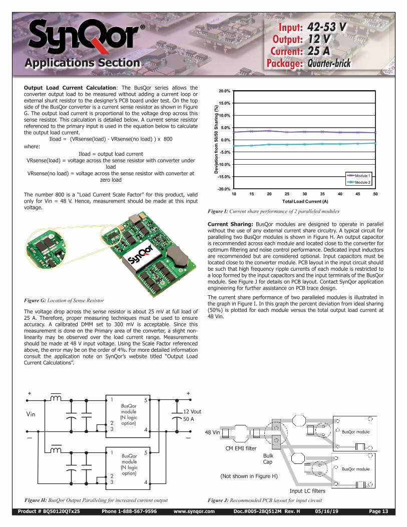
Output Load Current Calculation: The BusQor series allows the converter output load to be measured without adding a current loop or external shunt resistor to the designer’s PCB board under test. On the top side of the BusQor converter is a current sense resistor as shown in Figure G. The output load current is proportional to the voltage drop across this sense resistor. This calculation is detailed below. A current sense resistor referenced to the primary input is used in the equation below to calculate the output load current.
Iload = (VRsense(load) - VRsense(no load) ) x 800where:
Iload = output load currentVRsense(load) = voltage across the sense resistor with converter under
loadVRsense(no load) = voltage across the sense resistor with converter at
zero load
The number 800 is a “Load Current Scale Factor” for this product, valid only for Vin = 48 V. Hence, measurement should be made at this input voltage.
BusQor module(N logic option)
Vin
+ +
— —
1
23
1
23
5
4
5
4
BusQor module(N logic option)
-20.0%
-15.0%
-10.0%
-5.0%
0.0%
5.0%
10.0%
15.0%
20.0%
10 15 20 25 30 35 40 45 50
Dev
iatio
n fro
m 5
0/50
Sha
ring
(%)
Total Load Current (A)
Module 1
Module 2
CM EMI filterBulk Cap
Input LC filters
BusQor module
BusQor module
(Not shown in Figure H)
Figure G: Location of Sense Resistor
Figure H: BusQor Output Paralleling for increased current output
12 Vout50 A
Current Sharing: BusQor modules are designed to operate in parallel without the use of any external current share circuitry. A typical circuit for paralleling two BusQor modules is shown in Figure H. An output capacitor is recommended across each module and located close to the converter for optimum filtering and noise control performance. Dedicated input inductors are recommended but are considered optional. Input capacitors must be located close to the converter module. PCB layout in the input circuit should be such that high frequency ripple currents of each module is restricted to a loop formed by the input capacitors and the input terminals of the BusQor module. See Figure J for details on PCB layout. Contact SynQor application engineering for further assistance on PCB trace design.
The current share performance of two paralleled modules is illustrated in the graph in Figure I. In this graph the percent deviation from ideal sharing (50%) is plotted for each module versus the total output load current at 48 Vin.
Figure I: Current share performance of 2 paralleled modules
Figure J: Recommended PCB layout for input circuit
48 Vin
The voltage drop across the sense resistor is about 25 mV at full load of 25 A. Therefore, proper measuring techniques must be used to ensure accuracy. A calibrated DMM set to 300 mV is acceptable. Since this measurement is done on the Primary area of the converter, a slight non-linearity may be observed over the load current range. Measurements should be made at 48 V input voltage. Using the Scale Factor referenced above, the error may be on the order of 4%. For more detailed information consult the application note on SynQor’s website titled “Output Load Current Calculations”.
Product # BQ50120QTx25 Phone 1-888-567-9596 www.synqor.com Doc.#005-2BQ512M Rev. H 05/16/19 Page 14
Input: 42-53 V Output: 12 V Current: 25 A Package: Quarter-brickOrdering Information
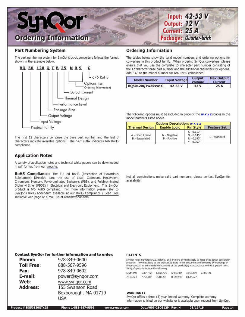
Part Numbering SystemThe part numbering system for SynQor’s dc-dc converters follows the format shown in the example below.
The first 12 characters comprise the base part number and the last 3 characters indicate available options. The “-G” suffix indicates 6/6 RoHS compliance.
Application NotesA variety of application notes and technical white papers can be downloaded in pdf format from our website.
RoHS Compliance: The EU led RoHS (Restriction of Hazardous Substances) Directive bans the use of Lead, Cadmium, Hexavalent Chromium, Mercury, Polybrominated Biphenyls (PBB), and Polybrominated Diphenyl Ether (PBDE) in Electrical and Electronic Equipment. This SynQor product is 6/6 RoHS compliant. For more information please refer to SynQor’s RoHS addendum available at our RoHS Compliance / Lead Free Initiative web page or e-mail us at [email protected].
Ordering InformationThe tables below show the valid model numbers and ordering options for converters in this product family. When ordering SynQor converters, please ensure that you use the complete 15 character part number consisting of the 12 character base part number and the additional characters for options. Add “-G” to the model number for 6/6 RoHS compliance.
The following options must be included in place of the w x y z spaces in the model numbers listed above.
Not all combinations make valid part numbers, please contact SynQor for availability.
Product Family
Package SizePerformance Level
Thermal Design
Output Current
6/6 RoHS
Options (see Ordering Information)
Input Voltage
Output Voltage
BQ 50 120 Q T B 25 N R S - G
Ordering Information
Model Number Input Voltage Output Voltage
Max Output Current
BQ50120QTw25xyz-G 42-53 V 12 V 25 A
Options Description: w x y zThermal Design Enable Logic Pin Style Feature Set
A - Open Frame B - Baseplated
N - Negative P - Positive
K - 0.110" N - 0.145" R - 0.180" Y - 0.250"
S - Standard
WARRANTYSynQor offers a three (3) year limited warranty. Complete warranty information is listed on our website or is available upon request from SynQor.
Contact SynQor for further information and to order: Phone: 978-849-0600 Toll Free: 888-567-9596 Fax: 978-849-0602 E-mail: [email protected] Web: www.synqor.com Address: 155 Swanson Road Boxborough, MA 01719 USA
PATENTS SynQor holds numerous U.S. patents, one or more of which apply to most of its power conversion products. Any that apply to the product(s) listed in this document are identified by markings on the product(s) or on internal components of the product(s) in accordance with U.S. patent laws. SynQor’s patents include the following:
6,545,890 6,894,468 6,896,526 6,927,987 7,050,309 7,085,146
7,119,524 7,765,687 7,787,261 8,149,597 8,644,027


![o a Err— 7. 5 Goa] 3 V furnieO o Brick Warehouse, …...3 V furnieO o Brick Warehouse, Harbor Store Google My Maps Created Date 2/1/2018 4:42:49 PM ...](https://static.fdocuments.us/doc/165x107/5f0847967e708231d4213986/o-a-erra-7-5-goa-3-v-furnieo-o-brick-warehouse-3-v-furnieo-o-brick-warehouse.jpg)