4701 nVision Operation Manual - Test & Measurement ... 2 nVision Operation Manual QUICKSTART nVision...
52
nVision Operation Manual for Reference Recorder & Lab Reference
Transcript of 4701 nVision Operation Manual - Test & Measurement ... 2 nVision Operation Manual QUICKSTART nVision...

nVision Operation Manual for Reference Recorder & Lab Reference

Contents
Overview. . . . . . . . . . . . . . . . . . . . . . . . . . . . . . . . . . . . . . . . . . . . . . . . . . . . . . . . . . . . . . . 1
Introduction . . . . . . . . . . . . . . . . . . . . . . . . . . . . . . . . . . . . . . . . . . . . . . . . . . . . . . . . . . . . . .1
Quickstart . . . . . . . . . . . . . . . . . . . . . . . . . . . . . . . . . . . . . . . . . . . . . . . . . . . . . . . . . . . . . . . .2
Functions . . . . . . . . . . . . . . . . . . . . . . . . . . . . . . . . . . . . . . . . . . . . . . . . . . . . . . . . . . . . . . 3
On/Off . . . . . . . . . . . . . . . . . . . . . . . . . . . . . . . . . . . . . . . . . . . . . . . . . . . . . . . . . . . . . . . . . . .3
Measurements & Recording . . . . . . . . . . . . . . . . . . . . . . . . . . . . . . . . . . . . . . . . . . . . . . . .3
Numerical Display Overview . . . . . . . . . . . . . . . . . . . . . . . . . . . . . . . . . . . . . . . . . . . . . . . .5
Graphical Display Overview . . . . . . . . . . . . . . . . . . . . . . . . . . . . . . . . . . . . . . . . . . . . . . . .5
Graphing . . . . . . . . . . . . . . . . . . . . . . . . . . . . . . . . . . . . . . . . . . . . . . . . . . . . . . . . . . . . . . . .6
Averaging Mode . . . . . . . . . . . . . . . . . . . . . . . . . . . . . . . . . . . . . . . . . . . . . . . . . . . . . . . . . .7
Diff erential Mode . . . . . . . . . . . . . . . . . . . . . . . . . . . . . . . . . . . . . . . . . . . . . . . . . . . . . . . . .7
Run Tags . . . . . . . . . . . . . . . . . . . . . . . . . . . . . . . . . . . . . . . . . . . . . . . . . . . . . . . . . . . . . . . . .8
Chassis . . . . . . . . . . . . . . . . . . . . . . . . . . . . . . . . . . . . . . . . . . . . . . . . . . . . . . . . . . . . . . . . . 9
Chassis Controls . . . . . . . . . . . . . . . . . . . . . . . . . . . . . . . . . . . . . . . . . . . . . . . . . . . . . . . . . .9
Serial Numbers . . . . . . . . . . . . . . . . . . . . . . . . . . . . . . . . . . . . . . . . . . . . . . . . . . . . . . . . . .13
nVision Reference Recorder Specifi cations . . . . . . . . . . . . . . . . . . . . . . . . . . . . . . . . . . .14
nVision Lab Reference Specifi cations . . . . . . . . . . . . . . . . . . . . . . . . . . . . . . . . . . . . . . . .15
Modules . . . . . . . . . . . . . . . . . . . . . . . . . . . . . . . . . . . . . . . . . . . . . . . . . . . . . . . . . . . . . . . 16
Module Installation Instructions . . . . . . . . . . . . . . . . . . . . . . . . . . . . . . . . . . . . . . . . . . . .16
Pressure Module (PM) Instructions . . . . . . . . . . . . . . . . . . . . . . . . . . . . . . . . . . . . . . . . .18
Pressure Module (PM) Specifi cations . . . . . . . . . . . . . . . . . . . . . . . . . . . . . . . . . . . . . . . .19
Barometric Reference (BARO) Module Instructions . . . . . . . . . . . . . . . . . . . . . . . . . . . .23
Barometric Reference (BARO) Module Specifi cations . . . . . . . . . . . . . . . . . . . . . . . . . .24
Absolute Pressure Specifi cations . . . . . . . . . . . . . . . . . . . . . . . . . . . . . . . . . . . . . . . . . . .25
Current, Voltage, and Switch Test (MA20) Module Instructions . . . . . . . . . . . . . . . . . .26
Current, Voltage, and Switch Test (MA20) Module Specifi cations . . . . . . . . . . . . . . . .28
Temperature (RTD100) Module Instructions . . . . . . . . . . . . . . . . . . . . . . . . . . . . . . . . .30
Temperature (RTD100) Module Specifi cations . . . . . . . . . . . . . . . . . . . . . . . . . . . . . . . .33
Resistance Temperature Detectors (RTD) . . . . . . . . . . . . . . . . . . . . . . . . . . . . . . . . . . . .34
Power . . . . . . . . . . . . . . . . . . . . . . . . . . . . . . . . . . . . . . . . . . . . . . . . . . . . . . . . . . . . . . . . . . 36
Battery Power (Reference Recorder only) . . . . . . . . . . . . . . . . . . . . . . . . . . . . . . . . . .36
USB Power (Reference Recorder only) . . . . . . . . . . . . . . . . . . . . . . . . . . . . . . . . . . . . .38
Reset (Reference Recorder only) . . . . . . . . . . . . . . . . . . . . . . . . . . . . . . . . . . . . . . . . . .38
Safety and Certifi cations . . . . . . . . . . . . . . . . . . . . . . . . . . . . . . . . . . . . . . . . 39
Hazardous Locations . . . . . . . . . . . . . . . . . . . . . . . . . . . . . . . . . . . . . . . . . . . . . . . . . . . . .39
Certifi cations . . . . . . . . . . . . . . . . . . . . . . . . . . . . . . . . . . . . . . . . . . . . . . . . . . . . . . . . . . . .39
Multi-language Safety Instructions . . . . . . . . . . . . . . . . . . . . . . . . . . . . . . . . . . . . . . . . .40
Support . . . . . . . . . . . . . . . . . . . . . . . . . . . . . . . . . . . . . . . . . . . . . . . . . . . . . . . . . . . . . . . 45
Troubleshooting . . . . . . . . . . . . . . . . . . . . . . . . . . . . . . . . . . . . . . . . . . . . . . . . . . . . . . . . .45
Calibration . . . . . . . . . . . . . . . . . . . . . . . . . . . . . . . . . . . . . . . . . . . . . . . . . . . . . . . . . . . . . .47
Accessories and Replacement Parts . . . . . . . . . . . . . . . . . . . . . . . . . . . . . . . . . . . . . . . . .48
Contact Us . . . . . . . . . . . . . . . . . . . . . . . . . . . . . . . . . . . . . . . . . . . . . . . . . . . . . . . . . . . . . .49
Trademarks . . . . . . . . . . . . . . . . . . . . . . . . . . . . . . . . . . . . . . . . . . . . . . . . . . . . . . . . . . . . .49
Warranty . . . . . . . . . . . . . . . . . . . . . . . . . . . . . . . . . . . . . . . . . . . . . . . . . . . . . . . . . . . . . . . .49

Overview 1
nVision Operation Manual
Overview
INTRODUCTION
Thank you for choosing the nVision Reference Recorder from Crystal Engineering Corporation. The philosophy behind nVision:
nVision lets you visualize measurements graphically, with or without a pc, in real time as it is being recorded. It is much easier to identify trends or anomalies
visually, than in tables of data or spreadsheets.
nVision is tremendously fl exible and can be confi gured to measure and record a variety of combinations of measurements. In addition to pressure, modules
for temperature, voltage and current can be used.
Because all of these inputs can be displayed individually as numbers or as graphs, or in combination with other inputs (numerically and graphically) we also
provide a way to simplify nVision, so you can limit the available screens to only those that are of use to your specifi c task.
Accuracy is up to 0.025 percent of reading – so any nVision can typically replace several gauges or calibrators you may have been using. The nVision is fully
temperature compensated – so there is no change in accuracy throughout the entire operating temperature range!
The nVision features two identical bays allowing confi guration of the reference recorder to meet your requirements. All modules are fi eld-replaceable allowing
you the fl exibility to react to changing needs and module calibration requirements.
The nVision’s case is made from a rugged injection molded polymer utilizing a gasket to seal the enclosure against dust and water intrusion. Even the mini
USB B connector is fully sealed (with or without the protective boot cover). Circuitry is mounted in a shock-absorbing elastomeric system and the batteries are
easily accessible by removing four captive screws.
Other features include:
• Log and display 500,000 points at up to 10 readings per second on up to two modules simultaneously
• Interactive real-time graphing of measurements
• ATEX / IECEx Scheme intrinsically safe (nVision Reference Recorder only)
• IP67 rated enclosure —1 meter immersion for 30 minutes (nVision Reference Recorder only)
• Uses Crystal’s CPF fi ttings and hose system (leak-free and fi nger-tight to 10 000 psi (700 bar)) U.S. Patent No. 8,794,677
We hope your nVision meets your expectations, and we’re interested in any comments or suggestions you may have. You can send us a note at:
[email protected]. Many features in this and our other products are a direct result of your comments!
Crystal Engineering is the company that designs, manufactures, and services the nVision reference recorders, XP2i series pressure gauges, 30 series pressure
calibrators, MultiCal multimeter pressure modules, and a variety of industry specifi c pressure measuring equipment.
Crystal Engineering pioneered features like full temperature compensation and “of reading” rated gauges and calibrators. Pressure measuring equipment is
the only thing we do and that’s why we say:
™
Your nVision can be customized to meet
your specifi c test needs through the use
of CrystalControl™ software. Your personal
computer can disable, enable, or modify a
variety of features of your nVision. Look for
the logo for user program-
mable features, like:
• User defi ned pressure units, and/or disable
unused pressure units
• Password protection to prevent unauthor-
ized changes to gauge settings and/or
product keypad access
• Expand or decrease allowable Zero range
• Set the gauge to a diff erent density of water
factor (4°C, 60°F, or 68°F)
• Store custom ID or tag numbers in
non-volatile memory
• Adjust calibration values
CrystalControl is included with your nVision,
and is also available as a download from our
website at ametekcalibration.com.

Overview 2
nVision Operation Manual
QUICKSTARTnVision Reference Recorder shown.
All instructions on this spread are also applicable to nVision Lab Reference
This icon represents a component that can be modifi ed with CrystalControl software
Upper Module Bay
Home button: Brings you back to the default screen
(Change Home Screen)
Next button: Progress through the display screens
LED Indication alerts:
: Flashes while recording
(Flashes quickly when recording ends)
: Flashes when a module's range is exceeded
Record button:
Start/Stop data recording
(Adjust Logging Interval)
Backlight button:
Turn on/off display backlight
(Adjust Backlight Shutoff )
Power button:
Turn your nVision on/off
Zero button: Press to zero Pressure Module reading (- - - - -)
Hold for 5 seconds to clear any zero value (- - -)
(Adjust Zero Limit)
Lower Module Bay
Setup Button:
Locate additional features:
• Clear Peaks
Units (Adjust Available units)
• PM Mode: Gauge or Absolute
Settings
• Contrast
• Lock/Unlock Chassis
Summary
• Chassis, Upper, Lower
Recording
• Start/Stop
• Erase All Runs
Navigation & Select
Back button:
Previous Display Screen
Power Icon Key - nVision Reference Recorder
Icon
DescriptionExternal Power(USB)
100% 75% 50% 25% 0%*
Power Remaining
* Replace Batteries or connect to USB Power
Power Icon Key - nVision Lab Reference
Icon
DescriptionExternal Power
(AC Adapter)USB Connection

Functions 3
nVision Operation Manual
Functions
ON/OFF
Power button
Press and hold the (power) button for 1 second to turn the nVision on or off . The nVision will automatically power down if not used for the time period
defi ned in CrystalControl.
Automatic Shutoff - Low Power Mode
Adjust your Automatic Shutoff time (shut off time in absence of key press) to optimize battery life. This feature is adjustable from 30
seconds to “always on.” During a recording, the nVision will enter Low Power Mode instead of shutting off .
When powered by USB, the nVision does not employ any power management strategies. Therefore, it will not automatically shut off to the settings defi ned by
CrystalControl.
During a recording with a Logging Interval of 1 reading/minute or slower, your nVision will enter Ultra-Low Power Mode after the fi rst reading elapses and the
Automatic Shutoff Timer runs out.
The Backlight Shutoff is set separately in CrystalControl. It is unaff ected by other settings.
MEASUREMENTS & RECORDING
Recording
The nVision can record at rates from 10 readings per second to 1 reading per hour as set in CrystalControl. Adjust your recording rate to optimize battery life
and data recording space.
Your nVision is capable of recording more than 500,000 data points when both module bays are populated. With one bay populated, this
number doubles. CrystalControl will give you a more accurate view of recording times based on the logging rate and enabled screens for your nVision.
When connected to CrystalControl you can confi gure, control, and graph an nVision recording directly from your PC, without handling the nVision chassis.
To start or stop a recording run from any screen:
1 Press the (record) button for one second.
Note: You may be prompted to enter a Run Tag, if enabled. For more information, see Run Tags.
2 The red LED will start fl ashing when the recording begins.
3 To stop recording, press the (record) button again. The red LED will fl ash twice.
Note: The nVision records data for all screens enabled in Crystal Control. Even if you are viewing data for the lower module numerical display,
data for the upper module will still record if any of the screens for that module are enabled. Use CrystalControl to check which data screens are enabled.

Functions 4
nVision Operation Manual
Zero
To zero the nVision:
• Press the (zero) button for at least 1 second while vented to atmosphere until the dashed lines (- - - - -) appear.
To clear the zero value:
• Hold the (zero) button for 5 seconds until the display changes from (- - - - -) to the zeroed value, then to (- - -).
You can adjust the Zero Limit at which the (zero) button will display “- -HI- -” in CrystalControl. You can also disable the (zero) button
entirely, by setting the zero value to a negative number less than -15 psi.
Note: If you attempt to zero the gauge with more pressure applied than the Zero Limit set in with CrystalControl, the command will be ignored, and “- -HI- -”
will display.
Note: You can never zero the BARO sensor.
! WARNING: This gauge can display zero pressure when connected to a source of pressure! Do not rely on the display indication before disconnecting—
it may not be indicating true pressure. Never disconnect pressure instrumentation without fi rst relieving system pressure!

Functions 5
nVision Operation Manual
Lower Module Screen
Dual Module Screen Data Point Screen (Single Sensor)
Upper Module Screen
Selectable Units (via Setup button)
(Enable, disable, or create units)Vertical Scale: Applied versus
full-scale pressure (Pressure Module Only)
Sensor Reading biased towards applicable module location in the chassis
Indicates current data point
Current readingDate & Time Stamp
High / Low:Peak always measured
at 10 readings per second
Filter: Average of most recent
20 readings
NUMERICAL DISPLAY OVERVIEW
Numerical Upper and Lower Module screens Numerical Dual Mode Screen(Both Sensors)
Data Point Counter Screen
Note:To change the displayed units
on any Numerical Display,
see the Units section.
Note:To change the displayed units
on any Graphical Display,
see the Units section.
BARO module reading
Lower Module Screen
Dual Module Screen
Upper Module Screen
For safety, live readings are displayed regardless of cursor location or zoom levelDate and Time Stamping
Date and Time Stamping
GRAPHICAL DISPLAY OVERVIEW
Graphical Upper and Lower Module screens Graphical Dual Mode Screen(Both Sensors)
Graphical BARO Screen(Both Sensors)
Dual Module Screen
Displays barometric pressure from BARO module vs. output from one pressure module (Upper or Lower)
Left y-axis indicates the scale of the lower module. Right y-axis indicates the scale of the upper module
Pressure module reading
Maximum WorkingPressure:
(Pressure Module Only)
/min:Rate of change per
minute
On all graphical screens the triple-arrow icon
indicates the module currently displayed

Functions 6
nVision Operation Manual
GRAPHING
Navigating the Graphical Display
In the graphical modes the nVision navipad enables you to control how you view your data. The () & () keys allow you to navigate to
specifi c points along your run, while displaying reading and time information. The () & () keys allow you to zoom in and out of your
recorded run to suit your needs.
Panning Across the Data Set
To inspect the latest or current data recording, use the () & () keys to move the cursor within the display window. During live recording, data streams
from the right side of graphical display screens. Therefore, the most recent data will always appear on the far right of the display.
Cursor location
Live recording area
Zooming in on Specifi c Data
To see more detail on the latest or current data recording, you may zoom in or out on your cursor.
1 Use the () and () arrows to zoom in or out in any graphical display, during or after recording.
2 To return to the fully zoomed out view (viewing the complete run) simply hold the () arrow for 5 seconds, or until you are completely zoomed out.
Normal View Zoom View
During any zooming keystroke a zoom in ( ) or zoom out ( ) icon appears
When zoomed in, small arrows appear on the horizontal time bar.

Functions 7
nVision Operation Manual
AVERAGING MODE
Averaging mode reports the average reading during the recorded run. If this screen is enabled, data displayed here represents the average of all past data
points, over the duration of a recording. The start date and time, duration of the recorded run, and the live reading are displayed.
nVision calculates averages as follows:
r1 + r2 + r3 ...+ rnn
rn = current readingn = total number of readings
Averaging Mode
DIFFERENTIAL MODE
The nVision automatically displays numerical and graphical diff erential screens if two similar module types are installed. ΔP becomes available if your nVision
is populated with two PM modules. ΔT becomes available if your nVision is populated with two RTD100 modules.
In the case of the pressure modules (PM), this mode does not require them to be the same full scale range.
! WARNING: Two MA20 modules cannot be installed at once. This confi guration may permanently damage your nVision.
In Diff erential Mode the ΔP or ΔT represents a fi ltered reading of the upper module – lower module + tare reading.
Filtered live reading of upper module
Filtered live reading of lower module
Tare value equalizes the upper and lower modules
Diff erential Mode
The units selected for this view are independent of the units selected for the other screens such as the Numerical or Graphical views. Data viewed in the
Graphical screens will represent the data acquired from either module and not represent the specialized view of the Diff erential Mode.
Note: To change the displayed units on any Diff erential Display, see the Units section.

Functions 8
nVision Operation Manual
Tare
Using the Tare function improves your diff erential measurement uncertainty signifi cantly if used properly. The Tare function equalizes (normalizes) the nVi-
sion’s two modules at a non-ambient datum. The Tare reading displays the same units as the main ΔP or ΔT reading.
If you apply the same static line pressure, temperature, or resistance signal to both sensors simultaneously, you should have a diff erential reading of zero. Due
to the allowable error tolerance for each module, the reading may not be zero. The Tare function allows you to normalize both readings so that the diff erential
reading is zero. This gives you a more accurate diff erential reading than if this process were not completed.
Note: Tare should be reestablished every time your measurement conditions change, including vent condition. For instance if your ΔP reading has 8 inH20 of
Tare at 1500 psi static, when you return to vent condition this 8 inH20 of Tare will remain in place on your ΔP reading until cleared with the Tare button.
To Tare:
1 Use the (next) button to select the Diff erential Mode Numerical Screen.
2 Press the (zero) button until the display fl ashes dashed lines (- - - - -).
3 To clear the Tare value in the Diff erential Mode, hold the button for 3 seconds until the main display readings change from (- - - - -) to (- - -).
RUN TAGS
Run Tags are 22 character identifi ers you can enter to name each data run. They are enabled by selecting the Enable Run Tags checkbox.
The Run Tags you choose will display in CrystalControl's DataViewer and your downloaded data.
To use Run Tags:
1 Press (record) from any screen. A QWERTY keyboard will appear, giving you the option to add your Run Tag.
2 Use the () , () , () , and () arrows and the (select) button to edit your Run Tag on the QWERTY keyboard.
3 Press the (next) button, or move to the onscreen checkbox and press the (select) button.
Your recording will begin immediately.
You can also enter up to fi ve predefi ned Run Tags when the Predefi ned Run Tags box is checked.
1 Press (record) from any screen.
2 Use the () , () arrows and the (select) button to choose a Run Tag from the list.
3 Use the () , () , () , and () arrows and the (select) button to edit your Run Tag on the QWERTY keyboard.
4 Press the (next) button, or move to the onscreen checkbox and press the (select) button.
Your recording will begin immediately.
Note: If you enable Run Tags in CrystalControl, you will be prompted to select a Run Tag prior to every recording. You can also see your Run Tag info through
the setup button during a recording. See View the current Run Tag during a recording for instructions.

Chassis 9
nVision Operation Manual
Chassis
CHASSIS CONTROLS
Setup Button
Pressing the (setup) button brings up a selectable menu including Clear Peaks, Units, Settings, Summary, and Recording. On the (navipad), use the
() and () arrows to move to the desired feature and use the (select) button or () and () arrows to move into the desired function.
The nVision Setup menu
Clear Peaks (Resetting Hi and Lo Peaks)
Note: Dashed lines will briefl y appear across the peak value indicators. Clearing the peaks will not aff ect the zero values or the Filter value.
Units
Selecting Units allows you to change the displayed units on any screen. See the module specifi cations in the Modules section for a list of available units. With
a BARO module installed, you can switch between absolute and gauge pressure. On the Diff erential Mode screen, you can switch the units of the diff erential
measurement. When you change the displayed units for a module, the units for that module will change in every screen—except Diff erential Mode.
Note: The unit displayed at the beginning of a recording run remains the default unit for that run. All other units enabled in
CrystalControl will be available in CrystalControl’s DataViewer.

Chassis 10
nVision Operation Manual
Changing Units—Single Module, Numerical or Graphical Screen
Changing Units—Dual Module, Numerical or Graphical Screen
Changing Units—Diff erential Screen
Changing Units—BARO, Numerical or Graphical Screen
Changing Between Absolute and Gauge Pressure—Numerical or Graphical Screen

Chassis 11
nVision Operation Manual
Settings
Adjust Contrast (100%) (50%)(75%)
Lock the nVision
The Screen Lock Password feature will also be found in Settings, if enabled in CrystalControl. Prevent access to your nVision by protecting
your device with a 4-digit keypad lockout set in CrystalControl.
To unlock the nVision, simply enter the 4 digit password with the arrow keys and press the (select) button. The correct password will allow you back into
standard nVision operation. An invalid code will reject your attempt and allow you to enter another password.
Note: In the event you lose the password, you will need to contact the factory for an unlock code, which will remove the password protection.

Chassis 12
nVision Operation Manual
Chassis Summary
• Serial Number
• Firmware Version
• CPLD Version
• Date/Time
• Automatic Shutoff
• Backlight Shutoff
• Logging Interval
• Message Store
• Installed Modules
Module
• Model
• Serial Number
• Firmware Version
• Calibration Date
• Calibration Due
• Message Store
• Userspan
• Available Units
Module Specifi c Information
• Temp. Coeffi cients (RTD100)
• Base Resistance (RTD100)
• Lead Type (RTD100)
• Zero Limit (PM)
Summary Screen
The Summary screen allows you to view details or settings in your chassis or module.
View a Module Summary
Once you have selected a summary screen, you may also use the () and () arrows to move to the next summary screen.
Press the (Setup) button again to exit the summary screen.
Note: If a BARO module is installed, BARO Module will appear in the Summary drop-down menu list below Lower Module.
Summary Contents
The specifi c information in the Summary screens are:

Chassis 13
nVision Operation Manual
Recording
Start a Recording
Press the (record) button until the red LED indicator fl ashes.
View the current Run Tag during a recording
Erase All Runs
A confi rmation screen will ask, Are You Sure?. Press (select) to continue and erase all the data runs on this nVision. Press the (back) button to cancel.
! CAUTION: Never remove power (either battery or USB) during the erasing process.
SERIAL NUMBERS
All serial numbers can be viewed using the nVision Summary screens or in CrystalControl.
Each product has a maximum of four serial numbers, one for the chassis and one for each of the modules (upper, lower, and BARO). Chassis serial numbers
are located in the power bay or on the rear of the product in the case of the Lab Reference. Module serial numbers are located on the module and can also be
viewed in the power bay of the Reference Recorder. Serial Numbers consist of 6 numbers, with the left most digit representing the year of manufacture. For
example: 937834 was manufactured during 2009.

Chassis 14
nVision Operation Manual
NVISION REFERENCE RECORDER SPECIFICATIONS
Temperature (Operating and Storage)
Operating & Compensated . . . . . . . -20 to 50°C (-4 to 122°F).
Storage . . . . . . . . . . . . . . . . . . . . . . . . . . - 40 to 75°C (-40 to 167°F).
Humidity
<95% Relative, non-condensing
IP Rating
IP67 rated enclosure (1m immersion for 30 min) per IEC 60529
Electrical Connection
Electrical Connection . . . . . . . . . . . . mini-USB B (environmentally sealed chassis connector).
nVision under USB power consumes less than 100 mA.
! WARNING: The mini USB B connector shall not be used within the hazardous atmosphere. It shall
be used in the non-hazardous atmosphere with either “Safety Extra Low Voltage
Circuits” (SELV) or “Protective Extra Low Voltage Circuits” (PELV). The USB connector
has a Um of 6V.
SELV and PELV defi nitions per IEC60079-11 are:
Safety extra-low voltage (SELV): Extra-low voltage system (i.e. normally not exceeding 50 VAC or 120
V ripple-free DC) electrically separated from earth and from other systems in such a way that a single
fault cannot give rise to an electrical shock.
Protective extra-low voltage (PELV): Extra-low voltage system which is not electrically separated from earth but which otherwise satisfi es the requirements
for SELV.
Note: A 50V center-tapped earth system is a PELV system.
Mounting
Permanent Mounting . . . . . . . . . . . . four M4 x 0.7 threaded inserts: 8mm deep (see drawing for location)
Enclosure
Impact resistant injection molded housing and elastomeric protective boot compatible with common industrial fl uids, including Skydrol.
Weight: 680g (1.5 lbs) including one each PM and RTD100 module, 4AA battery module, and protective boot.
512.00
0.6015
371.44
25
SENSORDIAPHRAGM
SURFACE
1.00
ALL DIMENSIONS ARE IN MILLIMETERS [INCHES] RTD100 MATING CONNECTORFOR RTD PROBE SHOWNINSTALLED
RTD100 CONNECTOR SHOWN WITHOUT PROTECTIVE CAP
PHILLIPS X 4THUMBSCREWS WITH
SHOWN4AA BATTERY MODULE
8MM [0.31 in] DEEPTHREADED INSERTSM4 X 0.7
4 PLACES
CL
40 X 12 [1.6 X 0.5] MOUNTING SURFACE
2 PL
210.81
1.202 PLACES
5.50140
30
0.75
FLATSWRENCH
19
3.93
ACCESSBATTERY
100
2.88
ACCESS
73
BATTERY
200.79
MINI USB-BACCESS
FLAP
[2.41]60
MEDIUM PRESSURE FEMALE (MPF)
PRESSURE MODULE (PM) SHOWNCRYSTAL CPF SYSTEM:
RTD100 MODULE SHOWNWITH INCLUDED PROTECTIVE CAP
[7.08]178
110[4.38]
204
MAXIMUMWITH TWOPRESSUREMODULES
8.05
TUBE SYSTEM(1/4" MEDIUM PRESSURE
WITH 7/16"-20 INTERNAL THREADS)
The nVision enclosure

Chassis 15
nVision Operation Manual
NVISION LAB REFERENCE SPECIFICATIONS
Temperature (Operating and Storage)
Operating & Compensated . . . . . . . 10 to 50°C (50 to 122°F).
Storage . . . . . . . . . . . . . . . . . . . . . . . . . . 0 to 75°C (32 to 167°F).
Humidity
<95% Relative, non-condensing
IP Rating
IP40 rated enclosure per IEC 60529
Electrical Connection
Electrical Connection (Communication) . . . mini-USB B.
Electrical Connection (Power) . . . . 100-240VAC, 50-60 Hz with international plug adapters.
! WARNING: nVision Lab Reference and the mini USB B shall not be used within hazardous
atmospheres.
Mounting
Rack Mount Kit . . . . . . . . . . . . . . . . . . two rack mount ears with hardware.
Enclosure
Enclosure. . . . . . . . . . . . . . . . . . . . Powder coated metal enclosure.
Weight. . . . . . . . . . . . . . . . . . . . . . . 2.2 kg (4.75 lbs) including two pressure modules.
ALL DIMENSIONS ARE IN MILLIMETERS [INCHES]
FEET WITH RUBBER PADS4 PLACES
KEYPAD
M4 X 6 THREAD4 PLACES
MINI USB-BINTERFACE
UPPER PORTPRESSURE MODULE (PM) SHOWNCRYSTAL CPF SYSTEM:WITH 7/16"-20 INTERNAL THREADS)
DISPLAY
LOWER PORTPRESSURE MODULE (PM) SHOWNCRYSTAL CPF SYSTEM:MEDIUM PRESSURE FEMALE (MPF)(1/4" MEDIUM PRESSURE TUBE SYSTEMWITH 7/16"-20 INTERNAL THREADS)
PANEL MOUNT FLANGESINCLUDED IN CRYSTAL ENGINEERINGKIT P/N 4302
294[11.6]
80[3.2]
68[2.7]
103[4.1]
150[5.9]
MAXIMUMWITH TWOPRESSUREMODULES
143[5.6]
120[4.7]
MAXIMUM
116[4.6]
280[11.02]
256[10.1]
FRONT FEET TILT FEATURE
SET SCREWS4 PLACESINCLUDED WITHKIT P/N 4302
6VDC JACKACCESS
ON REAR PANEL
The nVision Lab enclosure

Modules 16
nVision Operation Manual
Modules
MODULE INSTALLATION INSTRUCTIONS
The nVision’s upper and lower bays allow for removal of modules in the fi eld. All module changes should be completed in a dry, clean environment, indoors.
Proper electrostatic discharge (ESD) grounding techniques should be taken into account prior to the module change over. If you’re removing a module with-
out installing a replacement, a blank plate (P/N: BNKPLT) must be installed to ensure your IP67 rating and to protect the product.
! WARNING: Do not install two MA20 modules simultaneously. Permanent damage may occur.
! CAUTION: Do not proceed unless you have a suitable replacement module or blank plate for the module bay in question.
Note: Follow these steps to change modules.
1 Before removing or replacing any modules, ensure that all recorded data has been archived properly through the use of Export Data in
CrystalControl.
2 Clean exterior of nVision, if necessary, to ensure no moisture or foreign matter will enter the enclosure when disassembled.
3 Power off nVision and remove any existing power or USB connections.
! WARNING: Failure to disconnect nVision from 4AA, USB, or AC power before module removal or installation may cause damage.
4 Loosen the four T10 Torx screws retaining the module face plate and carefully pull the module straight out of the chassis (avoid twisting). Make note of the
orientation of module connector (located closest toward the display) in relation to the nVision chassis.
Note: Please ensure that the module's o-ring is also removed with the module.
(4x)
Note: Due the physical form and the IP67 sealing strategy employed, some modules may be diffi cult to remove. If necessary, connect a fi tting or RTD cable to
the appropriate module to aid in module removal. Never force the separation of a module from an nVision chassis.

Modules 17
nVision Operation Manual
5 Install a new module in the same orientation as the one removed in step 4. The tri-lobe design of the module will not allow improper installation; do not
force installation of the module as permanent damage may occur. To ensure an IP67 rated seal, lightly lubricate the module’s o-ring (P/N: 4110) with Dow
111 silicon lubricant or equivalent.
(4x)
Lightly lubricate the o-ring, then install the module in the proper orientation.
Note: If installing a Blank Plate, confi rm orientation is fl at and even within the module bay for proper sealing.
6 Tighten face plate T10 Torx screws to 50 in-oz (0.35 newton meter (N-m)) torque.
7 Replace power module/plug and tighten to 50 in-oz (0.35 newton meter (N-m)) torque to ensure IP67 seal. When power is fi rst applied the unit will automatically
turn on. Ensure that nVision recognizes the new module by confi rming in CrystalControl or the Summary screens.
8 Before using the nVision to record, Erase All Data. See Recording in the Chassis chapter.
9 If you have any problems during this process, check the Troubleshooting section for relevant information or contact us at
[email protected] or (805) 595-5477.

Modules 18
nVision Operation Manual
PRESSURE MODULE (PM) INSTRUCTIONS
Pressure Connection
Crystal CPF System: Medium Pressure Female (MPF) (1/4” medium pressure tube system with 7/16-20 threads). See our CPF Brochure for further information.
CPF o-ring size and material: AS568A-012, Viton 90 durometer (P/N 3981).
For most applications CPF Fittings can be hand tightened (no tools required). Wrench tightening is recommended (to achieve a metal to metal cone seal) for
applications where chemical compatibility of the process fl uid and the o-ring are a concern. Cone seals require only moderate assembly torque to seal up to
10 000 psi (700 bar). We recommend a tightening torque of 120 in-lbs ±20 in-lbs for our CPF fi ttings. Please note this is only a fraction of the typical torque
required to seal a 1/4” NPT fi tting. If a torque wrench isn’t practical to use, the fi ttings can be assembled as follows: Hand tighten fi tting fully
until the cone has bottomed out. Tighten an additional 20º using a wrench. Apply a small amount of media-compatible lubricant to the gland threads and
male cone to increase fi tting life, reduce the likelihood of galling, and promote sealing.
! CAUTION: To achieve CPF maximum allowable working pressures no o-ring substitutions are allowed. See our CPF brochure and
CES-003 CPF Safety Guide available from the website at ametekcalibration.com for further detail.
Measuring Vacuum
All versions of the nVision can be used to measure moderate vacuum.
When measuring pressure less than ambient barometric conditions, a minus (-) sign will appear.
! CAUTION: The nVision is not recommended for continuous use at high vacuum.
Water Density (Inches of Water)
The following applies only to models where inches of water is a selectable pressure unit. As shipped from the factory, the nVision is set to display inches of
water corresponding to the density of water at 4°C (39.2°F).
You may require a diff erent water density for your application. CrystalControl allows the user to select the appropriate water density desired
at 4°C (39.2°F), 20°C (68°F), or 15.6°C (60°F) temperatures.
Overpressure Conditions
The nVision will read pressure up to approximately 110% of the rated pressure range. Above 110% of the range the display will start fl ashing and the readings
will not be reliable. The zero function does not aff ect when the display starts fl ashing to indicate overpressure, so depending on the zero value it is possible
that the display can start fl ashing without the maximum pressure being displayed.
For instance, if a 100 psi nVision is zeroed when 30 psi is being applied, it will indicate that the overpressure condition has been reached at 80 psi
(i.e., 110% x 100 psi – 30 psi = 80 psi).
Overpressure can aff ect accuracy, but the eff ect is only temporary unless the sensor has been destroyed. See Pressure Module (PM) Specifi cations for maximum
allowable overpressure ratings.

Modules 19
nVision Operation Manual
PRESSURE MODULE (PM) SPECIFICATIONS
Pressure Module Tables
ModuleRange
0 - 30%Gauge Full Scale
30 - 110%Gauge Full Scale
psig ± (% Full Scale) ± (% of Reading)
psi
30 0.0075% 0.025%
100 0.0075% 0.025%
300 0.0075% 0.025%
1000 0.015% 0.05%
3000 0.015% 0.05%
10000 0.015% 0.05%
15000 0.015% 0.05%
barG ± (% Full Scale) ± (% of Reading)
bar
3 0.0075% 0.025%
10 0.0075% 0.025%
30 0.0075% 0.025%
100 0.015% 0.05%
300 0.015% 0.05%
700 0.015% 0.05%
1000 0.015% 0.05%
kPaG / MPaG ± (% Full Scale) ± (% of Reading)
kPa /
MPa
300 0.0075% 0.025%
1 0.0075% 0.025%
3 0.0075% 0.025%
10 0.015% 0.05%
30 0.015% 0.05%
70 0.015% 0.05%
100 0.015% 0.05%
kg/cm2G ± (% Full Scale) ± (% of Reading)
kg/cm2
3 0.0075% 0.025%
10 0.0075% 0.025%
30 0.0075% 0.025%
100 0.015% 0.05%
300 0.015% 0.05%
700 0.015% 0.05%
1000 0.015% 0.05%
Accuracy (Gauge)
0 to 30% of Full Scale . . . . . . . . . . . . . . . ±(0.0075% of Full Scale) or ±(0.015% of Full Scale)
30 to 110% of Full Scale . . . . . . . . . . . . . ±(0.025% of Reading) or ±(0.05% of Reading)
Vacuum . . . . . . . . . . . . . . . . . . . . . . . . . . . . For 100 psi / 10 bar / 1 MPa / 10 kg/cm² and lower
±(0.06% of Full Scale*)
For 300 psi / 30 bar / 3 MPa and 30 kg/cm²
±(0.06% of Full Scale*) ±1 LSD
*Full Scale = -14.5 psig, -1.0 bar, -99.9 kPa, -1.0 kg/cm2.
Accuracy specifi cations include all eff ects of linearity, hysteresis, repeatability, temperature, and stability for one year.
Note: Exposure to environmental extremes of temperature, shock, and/or vibration may warrant a more frequent
recertifi cation period.
PM modules must be exercised and re-zeroed whenever exposed to signifi cant changes in environmental conditions to achieve these
specifi cations. To exercise a gauge, cycle the gauge between zero (ambient barometric pressure) and the pressure of interest.
A properly exercised gauge will return to a zero reading (or return to the same ambient barometric reading).
! CAUTION: Pressure Modules (PM) are not recommended for continuous use at high vacuum.

Modules 20
nVision Operation Manual
Accuracies, Ranges, and Resolutions
psi bar kPa/MPa kg/cm2 Overpressure psi kg/cm2 inHg inH20 * mmHg mmH20 kPa bar mbar MPa
30PSI 3.0 x 0.001 0.0001 0.001 0.01 0.01 1 0.01 0.0001 0.1
3BAR 3.0 x 0.001 0.0001 0.001 0.01 0.01 1 0.01 0.0001 0.1
300KPA 3.0 x 0.01 0.0001 0.1
3KG 3.0 x 0.001 0.0001 0.001 0.01 0.01 1 0.01 0.0001 0.1
100PSI 2.0 x 0.001 0.0001 0.01 0.1 0.1 1 0.01 0.0001 0.1 0.00001
10BAR 2.0 x 0.001 0.0001 0.01 0.1 0.1 1 0.01 0.0001 0.1 0.00001
1MPA 2.0 x 0.01 0.0001 0.1 0.00001
10KG 2.0 x 0.001 0.0001 0.01 0.1 0.1 1 0.01 0.0001 0.1 0.00001
300PSI 2.0 x 0.01 0.001 0.01 0.1 0.1 0.1 0.001 1 0.0001
30BAR 2.0 x 0.01 0.001 0.01 0.1 0.1 0.1 0.001 1 0.0001
3MPA 2.0 x 0.1 0.001 1 0.0001
30KG 2.0 x 0.01 0.001 0.01 0.1 0.1 0.1 0.001 1 0.0001
1KPSI 2.0 x 0.1 0.001 0.1 0.1 0.001 0.0001
100BAR 2.0 x 0.1 0.001 0.1 0.1 0.001 0.0001
10MPA 2.0 x 0.1 0.001 0.0001
100KG 2.0 x 0.1 0.001 0.1 0.1 0.001 0.0001
3KPSI 1.5 x 0.1 0.01 0.1 1 0.01 0.001
300BAR 1.5 x 0.1 0.01 0.1 1 0.01 0.001
30MPA 1.5 x 1 0.01 0.001
300KG 1.5 x 0.1 0.01 0.1 1 0.01 0.001
10KPSI 1.5 x 1 0.01 1 0.01 0.001
700BAR 1.5 x 1 0.01 1 0.01 0.001
70MPA 1.5 x 1 0.01 0.001
700KG 1.5 x 1 0.01 1 0.01 0.001
15KPSI 1.3 x 1 0.01 1 0.01 0.001
1000BAR 1.3 x 1 0.01 1 0.01 0.001
100MPA 1.3 x 1 0.01 0.001
1000KG 1.3 x 1 0.01 1 0.01 0.001
0.025%of Readingmodules
0.05%of Readingmodules
Reference Recorder Numbering System
Product ID PowerUpper Chassis
ModuleLower Chassis
ModuleBARO Module
(Optional)
NV – 4AA – – –
PM PM No: (omit)
MA20 MA20 Yes: BARO
RTD100 RTD100
Lab Reference Numbering System
Product ID PowerUpper Chassis
ModuleLower Chassis
ModuleBARO Module
(Optional)
NL – LAB – – –
PM PM No: (omit)
MA20 MA20 Yes: BARO
RTD100 RTD100
Sample Part Numbers
NL-LAB-30PSI-1KPSI
NL-LAB-MA20-3KPSI-BARO
Sample Part Numbers
NV-4AA-30PSI-3KPSI-BARO
NV-4AA-RTD100-10KPSI
To order the Reference recorder or Lab Reference with a single module, enter BNKPLT (blank plate) for either the upper or lower chassis module.
* Density of water can be set to 4°C, 60°F or 20°C /68°F with CrystalControl software .

Modules 21
nVision Operation Manual
Diff erential Pressure Measurement Uncertainties without Tare
The total nVision Reference Calibrator measurement uncertainty in the ΔP mode confi guration will need to consider the uncertainties of both pressure mod-
ules. We recommend the module uncertainties to be combined with the preferred square root of the sum of the squares (or “root sum squares”) method.
The following table lists the possible combinations of combining Pressure Modules (PM) with diff erent accuracy statements. The uncertainties reported below
are without using the Tare feature which will greatly improve your measurement uncertainty.
Upper Pressure
Module Uncertainties
(of Static Line Pressure)
(of Reading)
0.025% 0.05%
Lower Pressure
Module Uncertainties
(of Static Line Pressure)
(of Reading)
0.025% 0.035% 0.056%
0.05% 0.056% 0.071%
Diff erential Pressure Measurement Uncertainties with Tare
The Tare function can improve measurement uncertainties on two modules with the same full scale pressure range installed into one nVision Reference
Recorder.
The following specifi cations apply to the measurement system with a logging interval of 1 reading/second or slower:
Full Scale Range of Both Sensors The Greater of (+/–)
psi bar kPa/MPa kg/cm2 psi mbar inH2O mmH2O % of DP Reading
30 3 300 3 0.0005 0.04 0.014 0.4 or 0.025%
100 10 1 10 0.0015 0.10 0.04 1.0 0.025%
300 30 3 30 0.005 0.4 0.14 4.0 0.025%
1000 100 10 100 0.02 1.0 0.4 10.0 0.05%
3000 300 30 300 0.05 4.0 1.4 n/a 0.05%
10000 700 70 700 0.2 10.0 4.0 n/a 0.05%
15000 1000 100 1000 0.3 15.0 6.0 n/a 0.05%
Unit must be enabled in CrystalControl

Modules 22
nVision Operation Manual
Diff erential Pressure Resolution
psi bar kPa/MPa kg/cm2 psi kg/cm2 inHg inH2O mmHg mmH2O kPa bar mbar MPa
30 3 300 3 0.0001 0.00001 0.0001 0.001 0.001 0.1 0.001 0.00001 0.01 0.00001
100 10 1 10 0.0001 0.00001 0.001 0.01 0.01 0.1 0.001 0.00001 0.01 0.00001
300 30 3 30 0.001 0.0001 0.001 0.01 0.01 0.1 0.01 0.0001 0.1 0.00001
1000 100 10 100 0.01 0.0001 0.01 0.1 0.1 0.1 0.01 0.0001 0.1 0.00001
3000 300 30 300 0.01 0.001 0.01 0.1 0.1 n/a 0.1 0.001 0.1 0.0001
10000 700 70 700 0.1 0.001 0.1 0.1 0.1 n/a 0.1 0.001 0.1 0.0001
15000 1000 100 1000 0.1 0.001 0.1 0.1 0.1 n/a 0.1 0.001 0.1 0.0001
Unit must be enabled in CrystalControl
User Defi ned Units
The nVision gives you the ability to create your own custom User Defi ned Unit based on pressure. Implement your slope (user factor) and
off set (off set factor) in CrystalControl. See CrystalControl application and manual for details.
Pressure Conversions
1 psi =
27.6806 inH2O (water at 4°C [39.2°F])
27.7070 inH2O (water at 15.6°C [60°F])
27.7292 inH2O (water at 20°C [68°F])
2.03602 inHg (mercury at 0°C [32°F])
51.7149 mmHg (mercury at 0°C [32°F])
703.087 mmH2O (water at 4°C [39.2°F])
0.070307 kg/cm2
68.948 mbar
6.8948 kPa
0.068948 bar
0.006895 MPa
Logging Interval
Fastest Logging Interval . . . . . . . . . . 10 readings per second
Media Compatibility
Liquids and gases compatible with sensor and CPF fi tting system:
Wrench-tight . . . . . . . . . . . . . . . . . . . . 316 Stainless Steel
Finger-tight. . . . . . . . . . . . . . . . . . . . . . 316 Stainless Steel and Viton (internal MPF o-ring)

Modules 23
nVision Operation Manual
BAROMETRIC REFERENCE (BARO) MODULE INSTRUCTIONS
Installation of the BARO module in the power bay allows you to convert your gauge pressure measurement to the absolute scale if so
desired. You may also view the barometric reference reading directly on a dedicated numerical screen. When the BARO module is installed, it may also be
disabled in CrystalControl to conserve battery power, however your nVision will not be able to display absolute readings unless it is active.
Installation
The BARO module is located in the power bay of the nVision. nVision Lab Reference units must have BARO installation done at the factory. As with the
traditional modules, installation of the BARO module should be done in a ESD compliant, dry, clean environment, using the instructions below.
! CAUTION: The BARO module requires CPLD version 6 or greater to operate properly. If you have CPLD 5 or earlier the nVision must return to the
factory for updating. You may determine your CPLD version in the Chassis Summary screen or in CrystalControl.
1 Place the nVision face down on clean stable work surface.
2 Remove USB power connection and power pack from the nVision.
3 Remove your BARO module from factory packaging, grasp the cover, and orient as shown.
4 Slide the BARO module into the connector system.
5 Insert screw through cover and into the nVision, and tighten to 16 in-oz (0.11 newton meter (N-m)) torque to secure BARO module properly.
Note: Remember to enable the module in CrystalControl if module is a new installation.
Note: Reset the nVision chassis after enabling or disabling the BARO.
BARO module installation.

Modules 24
nVision Operation Manual
BAROMETRIC REFERENCE (BARO) MODULE SPECIFICATIONS
Absolute pressure mode is achieved by using the BARO Reference Module to establish a datum. The PM and BARO sensor uncertainties were combined to
establish a new accuracy statement for readings taken in the absolute mode. It must be noted that the accuracy statement is valid for readings of 1 barA or
greater.
Accuracy
± 0.00725 psi, ± 0.5 mbar
Accuracy specifi cations include all eff ects of linearity, hysteresis, repeatability, temperature, and stability within the specifi ed operating temperature range
for one year.
Note: Exposure to environmental extremes of temperature, shock, and/or vibration may warrant a more frequent recertifi cation period.
Ranges, Resolutions, and Units
Range . . . . . . . . . . . . . . . . . . . . . . . . . . . 10.153 to 15.954 psiA, 700 to 1100 mbarA
Units and Resolution
psi . . . . . . . . . . . . . . . . . . . . . . . . . . . . . . 0.001
inHg . . . . . . . . . . . . . . . . . . . . . . . . . . . . . 0.001
mmHg . . . . . . . . . . . . . . . . . . . . . . . . . . 0.01
mbar . . . . . . . . . . . . . . . . . . . . . . . . . . . . 0.1
Logging Interval
Fastest Logging Interval . . . . . . . . . . 10 readings per second
Pressure Connection
Cylindrical sensor fi tting of 5.8mm OD. A fl exible 4.8 mm [3/16"] ID tube is recommended to connection for both nVision chassis forms.
Mounting
BARO Module is secured using 3/8” 4-40 plastic screw.
! WARNING: Plastic non-conductive screw must be used to comply with hazardous locations requirements.
! CAUTION: Direct contact with barometric sensor may cause permanent damage. Direct sunlight on exposed BARO sensor may aff ect readings slightly.

Modules 25
nVision Operation Manual
ABSOLUTE PRESSURE SPECIFICATIONS
psiA (Pressure with BARO module)
30 psi module
0.200 to 14.500 psiA: ±0.011 psiA
14.500 to 44.500 psiA: ±(0.025% of Reading)
+ 0.003 psiA
100 psi module
0.200 to 14.500 psiA: ±0.011 psiA
14.500 to 44.500 psiA: ± 0.011 psiA
44.500 to 114.500 psiA: ±(0.025% of Reading)
300 psi module
0.20 to 14.50 psiA: ±0.01 psiA
14.50 to 104.50 psiA: ± 0.03 psiA
104.50 to 314.50 psiA: ±(0.025% of Reading)
1000 psi module
14.5 to 314.5 psiA: ± 0.2 psiA
314.5 to 1014.5 psiA: ±(0.05% of Reading)
3000 psi module
14.5 to 914.5 psiA: ± 0.5 psiA
914.5 to 3014.5 psiA: ±(0.05% of Reading)
10 000 psi module
15 to 3015 psiA: ± 2 psiA
3015 to 10 015 psiA: ±(0.05% of Reading)
15 000 psi module
15 to 4515 psiA: ± 3 psiA
4515 to 15 015 psiA: ±(0.05% of Reading)
barA (Pressure with BARO module)
3 bar module
0.0138 to 1.0000 barA: ±0.0008 barA
1.0000 to 4.0000 barA: ±(0.025% of Reading)
+0.0003 barA
10 bar module
0.0138 to 1.0000 barA: ±0.0008 barA
1.0000 to 4.0000 barA: ± 0.0010 barA
4.0000 to 11.0000 barA: ±(0.025% of Reading)
30 bar module
0.014 to 1.000 barA: ±0.001 barA
1.000 to 10.000 barA: ± 0.003 barA
10.000 to 31.000 barA: ±(0.025% of Reading)
100 bar module
1.000 to 31.000 barA: ± 0.015 barA
31.000 to 101.000 barA: ±(0.05% of Reading)
300 bar module
1.00 to 91.00 barA: ± 0.05 barA
91.00 to 301.00 barA: ±(0.05% of Reading)
700 bar module
1.00 to 211.00 barA: ± 0.11 barA
211.00 to 701.00 barA: ±(0.05% of Reading)
1000 bar module
1.00 to 301.00 barA: ± 0.15 barA
301.00 to 1001.00 barA: ±(0.05% of Reading)
MPaA (Pressure with BARO module)
300 kPa module
1.38 to 100.00 kPaA: ±0.08 kPaA
100.00 to 400.00 kPaA: ±(0.025% of Reading)
+0.03 kPaA
1 MPa module
0.00138 to 0.10000 MPaA: ±0.00008 MPaA
0.10000 to 0.40000 MPaA: ± 0.00010 MPaA
0.40000 to 1.10000 MPaA: ±(0.025% of Reading)
3 MPa module
0.0014 to 0.1000 MPaA: ±0.0001 MPaA
0.1000 to 1.000 MPaA: ± 0.0003 MPaA
1.000 to 3.1000 MPaA: ±(0.025% of Reading)
10 MPa module
0.1000 to 3.1000 MPaA: ± 0.0015 MPaA
3.1000 to 10.1000 MPaA: ±(0.05% of Reading)
30 MPa module
0.100 to 9.100 MPaA: ± 0.005 MPaA
9.100 to 30.100 MPaA: ±(0.05% of Reading)
70 MPa module
0.100 to 21.100 MPaA: ± 0.011 MPaA
21.100 to 70.100 MPaA: ±(0.05% of Reading)
100 MPa module
0.100 to 30.100 MPaA: ± 0.015 MPaA
30.100 to 100.100 MPaA: ±(0.05% of Reading)
kg/cm2A (Pressure with BARO module)
3 kg/cm2 module
0.0141 to 1.0000 kg/cm2A: ±0.0008 kg/cm2A
1.0000 to 4.0000 kg/cm2A: ±(0.025% of Reading)
+0.0003 kg/cm2A
10 kg/cm2 module
0.0141 to 1.0000 kg/cm2A: ±0.0008 kg/cm2A
1.0000 to 4.0000 kg/cm2A: ± 0.0010 kg/cm2A
4.0000 to 11.0000 kg/cm2A: ±(0.025% of Reading)
30 kg/cm2 module
0.014 to 1.000 kg/cm2A: ±0.001 kg/cm2A
1.000 to 10.000 kg/cm2A: ± 0.003 kg/cm2A
10.000 to 31.000 kg/cm2A: ±(0.025% of Reading)
100 kg/cm2 module
1.000 to 31.000 kg/cm2A: ± 0.015 kg/cm2A
31.000 to 101.000 kg/cm2A: ±(0.05% of Reading)
300 kg/cm2 module
1.00 to 91.00 kg/cm2A: ± 0.05 kg/cm2A
91.00 to 301.00 kg/cm2A: ±(0.05% of Reading)
700 kg/cm2 module
1.00 to 211.00 kg/cm2A: ± 0.11 kg/cm2A
211.00 to 701.00 kg/cm2A: ±(0.05% of Reading)
1000 kg/cm2 module
1.00 to 301.00 kg/cm2A: ± 0.15 kg/cm2A
301.00 to 1001.00 kg/cm2A: ±(0.05% of Reading)

Modules 26
nVision Operation Manual
CURRENT, VOLTAGE, AND SWITCH TEST (MA20) MODULE INSTRUCTIONS
The nVision MA20 module has three operational modes: current measurement, voltage measurement, and switch test. Each mode may be selected via the
Setup menu, and can only be operated one at a time.
To ensure proper connection to the MA20 Module use the following strategy:
1 Ensure that power is off on the circuit that you are about to measure.
2 Ensure your nVision is in correct MA20 Mode: mA, %4-20mA, %10-50mA, Voltage, or Switch Test.
3 Insert the Negative (black) 2mm lead jack to the proper location (black terminal) on the MA20 module. Connect the other end of the black lead to the
appropriate terminal of the source.
4 Insert the Positive (red) 2mm lead jack to the proper location (red terminal) on the MA20 module. Connect the other end of the red lead to the appropriate
terminal of the source.
5 Power up circuit and measure or record the readings as appropriate.
6 Never change modes or electrical sources without fi rst removing the nVision from the circuit. Failure to do so may damage the nVision.
! WARNINGS: The following warnings apply to the MA20 module:
• Never install two (2) MA20 modules simultaneously. This confi guration may permanently damage your nVision.
• Never exceed the maximum specifi ed voltage or current ratings on the MA20 inputs. Doing so may permanently damage the MA20 module.
• Check the test leads for continuity before using. Replace damaged test leads. Do not use the probes if they are cracked, have damaged insulation,
exposed metal, or high resistance.
• Always remove the test leads from the module before opening the battery compartment.
• When using test lead probes, always make sure your fi ngers are behind the fi nger guards on the probes.
• Never connect more than two (2) test leads to a MA20 module at a time.
Current Mode
The nVision is capable of measuring current in three diff erent modes. They are:
• mA: Measured current is displayed (mA). The module is capable of measuring inputs up to 55mA
• 4–20%: Current is displayed as a percentage of the 4–20mA current range, where 4mA = 0%, and 20mA = 100%
• 10–50%: Current is displayed as a percentage of the 10–50mA current range, where 10mA = 0%, and 50mA = 100%

Modules 27
nVision Operation Manual
Current Measurement
The nVision may be used to measure current up to 50mA. Select the desired current mode through the Setup menu to properly confi gure the nVision prior to
connection and use.
Current Measurement with HART Resistor
The nVision may be used to measure current in a circuit that includes a HART transmitter or device. For devices that use the HART protocol, a load resistor
must be placed in the loop. The HART input on the MA20 provides a 250 Ohm load resistor. Select the desired current mode through the Setup menu to
properly confi gure the nVision prior to connection and use.
MA20 module Current Measurement connection. MA20 module with HART load resistor.
Voltage Mode
The nVision may be used to measure voltages up to 28VDC. Select the Voltage mode through the Setup
menu to properly confi gure the nVision prior to connection and use.
MA20 module Voltage connection.

Modules 28
nVision Operation Manual
Switch Test Mode
The nVision may be used to detect switch closures. Select the Switch Test mode through the Setup menu to
properly confi gure the nVision prior to connection and use. The illustration denotes the proper Switch Test
connection scheme to the MA20 module.
MA20 module Switch Test connection.
CURRENT, VOLTAGE, AND SWITCH TEST (MA20) MODULE SPECIFICATIONS
Modes
Current mA % 4–20, %10–50
Current with HART Resistor mA % 4–20, %10–50
Voltage V
Switch Detection Open Closed
Connection
2mm banana jacks for sheathed plugs. 12.7mm (0.5 in) spacing.
Terminals
MA20 Functional Diagram
mA
HART250 Ohm
Resettable Fuse
V
Common
Voltage Measurement
Current Measurement
Switch Test

Modules 29
nVision Operation Manual
Logging Interval
Fastest Logging Interval. . . . . . . 6 readings per second.
Note: Although nVision logging interval may be set to a faster rate, the MA20 module will update the reading at 6 times per second.
ATEX and IECEx Scheme Entity Parameters
The MA20 Module has these specifi c input entity parameters:
Ui = 28 V Uo = 6.6 V
li = 93.3 mA lo = 4.45 mA
Pi = 653.3 mW Po = 7.34 mW
Ci = 0.36 uF Co = 0.5 uF**
Li = 39.1 uH Lo = 12 uH*
* Total cable inductance between all modules
** Dependent on the supply to the terminals but shall not be greater than 0.5 uF
Current (mA) Input
Accuracy
±(0.015% of reading + 0.002mA)
Accuracy specifi cations include all eff ects of linearity, hysteresis, repeatability, temperature, and stability within the specifi ed operating temperature range
for one year.
Note: Exposure to environmental extremes of temperature, shock, and/or vibration may warrant a more frequent recertifi cation period.
Ranges, Resolutions, and Units
Range . . . . . . . . . . . . . . . . . . . . . . . . . . . 0 to 55mA (MA20)
Max Allowable Current . . . . . . . . . . . 93.3mA
Note: Inputs protected by resettable fuse
Resolution . . . . . . . . . . . . . . . . . . . . . . . 0.001mA or 0.01%
Units . . . . . . . . . . . . . . . . . . . . . . . . . . . . mA, % 4-20, %10-50
mA Input
Input Resistance . . . . . . . . . . . . . . . . . < 17.2 Ω
Voltage Burden @ 50mA . . . . . . . . . < 0.86 V
Voltage Burden @ 20mA . . . . . . . . . < 0.35 V
HART mA Input
HART Resistance . . . . . . . . . . . . . . . . . 250 Ω

Modules 30
nVision Operation Manual
Voltage (V) Input
Accuracy
±(0.015% of reading + 0.002VDC)
Accuracy specifi cations include all eff ects of linearity, hysteresis, repeatability, temperature, and stability within the specifi ed operating temperature range
for one year.
Note: Exposure to environmental extremes of temperature, shock, and/or vibration may warrant a more frequent recertifi cation period.
Ranges, Resolutions, and Units
Range . . . . . . . . . . . . . . . . . . . . . . . . . . . 0 to 28VDC
Max Allowable Voltage . . . . . . . . . . . 30VDC
Resolution . . . . . . . . . . . . . . . . . . . . . . . 0.001VDC
Units . . . . . . . . . . . . . . . . . . . . . . . . . . . . VDC
Switch Test
Switch Detection
Switch States . . . . . . . . . . . . . . . . . . . . Dry Contact
Closed State Resistance . . . . . . . . . . < 10 Ω
Open State Resistance . . . . . . . . . . . > 10 MΩ
TEMPERATURE (RTD100) MODULE INSTRUCTIONS
Your nVision has the ability to measure temperature very accurately if populated with an RTD100 module. With this system you may connect your resistance
temperature detector (platinum RTD) or platinum resistance thermometer (PRT) to the nVision using the provided IP67 rated connector system (P/N: 3953).
Once the sensing element is connected, you may display the temperature reading in your desired unit. The nVision can also measure electrical resistance (Ω)
to help in troubleshooting your resistance based sensing element.
Temperature Coeffi cient of Resistance (TCR)
Your nVision comes pre-loaded with several common RTD sensing element TCR values with the appropriate Callendar-Van Dusen Coeffi cients to convert your
resistance measurement to the appropriate temperature measurement. The available 100Ω platinum RTD TCRs are:
• Pt100 (385) Euro
• Pt100 (3911) US
• Pt100 (3926)
Simply select the desired TCR or coeffi cient values in CrystalControl for use on the nVision. You may also view the Summary page to confi rm
you have selected the correct setting for your sensing element.

Modules 31
nVision Operation Manual
Connecting your RTD to the RTD100 Module
Your nVision RTD100 module has been shipped with an IP67 rated, M8 connector (P/N: 3953). The terminal block based connector allows you to attach your
RTD sensor for 2-, 3-, or 4-wire connections. Care must be taken to install the RTD connector shell properly to ensure the robust IP67 sealing.
1 RTD sensor element connection requirements:
• 100Ω Platinum RTD with:
• TCR of 385, 3926, or 3911
• Cable diameter of 3.5 to 5.0mm [0.14 to 0.2 inches] with smooth, continuous covering adequate for IP67 sealing.
• Stranded conductor cross section of 0.14 to 0.5mm2 [0.0002 to 0.0008 in2].
2 For your ease in sourcing this connector, the following sources of supply may be used:
• Phoenix Contact:
• Order Number: 1501265, or Part Number: SACC-M8MS-4CON-M-SW
• Binder:
• Part Number 99-3383-100-04
3 RTD sensor element cable preparation:
(a) Strip approximately 12.0mm [0.5 in] outer insulation from RTD cable.
(b) Strip the individual RTD element sense wires approximately 4.0mm [0.16 in].
(c) Install 3 piece sealing system onto the cable assembly. Take care to place parts in proper order and orientation.
12.0 mm
4.0 mm
Lubricate here withDOW 111 (See Step 4)
Wiring connection hardwaremay vary.

Modules 32
nVision Operation Manual
(d) Install your RTD sense element wires as appropriate for your confi guration (see illustration below), and tighten the set screws.
(e) Confi rm correct orientation of element wires in connected state.
2-wire 3-wire 4-wire
4 Lubricate o-ring and thread system with Dow 111 or equivalent in location near terminal block as required to prevent water intrusion when connector shell
is installed. Thread shell in place until tight.
5 Leak check to ensure water tight seal. If any leaking occurs, rework and lubricate as necessary. If leak-free, your RTD sensor is ready to use with the nVision
Reference Recorder.
Note: Your nVision has the RTD100 module TCR set to Pt100 (385) Euro. Modify this setting in CrystalControl as needed.
Modifying the Base Resistance (Ro)
As with any measurement device, it is possible the sensor will drift over time or from extreme temperatures. The nVision allows a user defi ned off set to the
100Ω base resistance experienced at 0ºC if needed to improve the performance of your sensor.
Diff erential Temperature
The Tare function also allows you to equalize the diff erential temperature or resistance measurements to improve your measurement accuracy. Therefore,
if you apply the same temperature or resistance signal to both RTD100 sensor elements simultaneously you should have a ΔT reading of zero. Due to the al-
lowable error tolerance for each module, the reading may not be zero. The Tare function allows you to normalize both of these readings so that the ΔT reading
is zero. Therefore, you will have a much more accurate ΔT reading than you normally would have if this process was not completed. Note that generally ac-
cepted lab practices should be followed when trying to establish a common temperature measurement on two independent sensors.
The Tare should be reestablished every time you are at a new temperature or resistance. For instance if your ΔT reading has 0.2°C of Tare at 220°C, when you
return to ambient conditions this 0.2°C of Tare will remain in place on your ΔT reading until cleared with the button.
Diff erential Temperature Measurement Uncertainties without Tare
The RTD100 module is capable of both temperature and resistance measurements. The resistance measurement uncertainty can be calculated by
combining the uncertainties of the two resistance measurements. The following formulas describe the combined uncertainty of two RTD100 Module
resistance measurements.
Modules 33
nVision Operation Manual
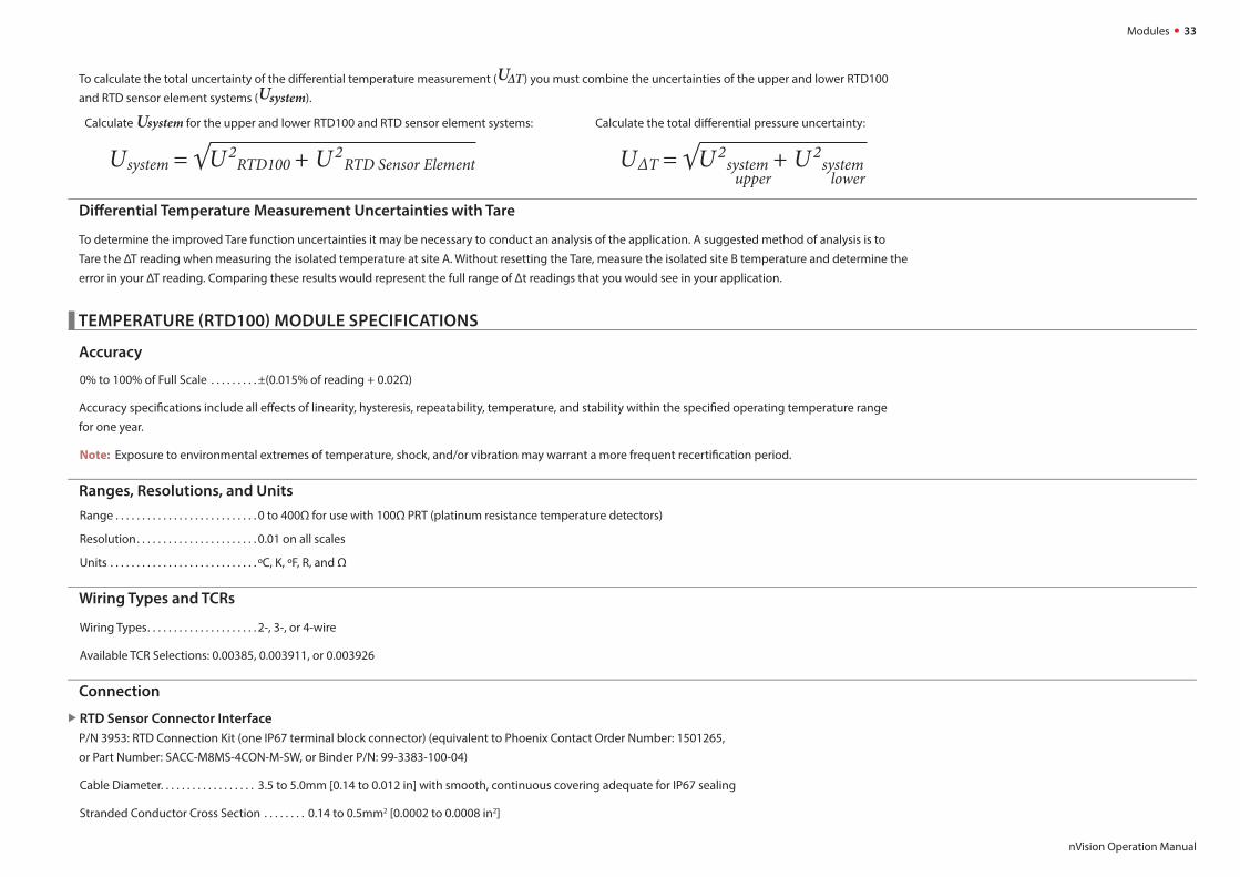
To calculate the total uncertainty of the diff erential temperature measurement (UΔT) you must combine the uncertainties of the upper and lower RTD100
and RTD sensor element systems (Usystem).
Calculate Usystem for the upper and lower RTD100 and RTD sensor element systems: Calculate the total diff erential pressure uncertainty:
Diff erential Temperature Measurement Uncertainties with Tare
To determine the improved Tare function uncertainties it may be necessary to conduct an analysis of the application. A suggested method of analysis is to
Tare the ΔT reading when measuring the isolated temperature at site A. Without resetting the Tare, measure the isolated site B temperature and determine the
error in your ΔT reading. Comparing these results would represent the full range of Δt readings that you would see in your application.
TEMPERATURE (RTD100) MODULE SPECIFICATIONS
Accuracy
0% to 100% of Full Scale . . . . . . . . . ±(0.015% of reading + 0.02Ω)
Accuracy specifi cations include all eff ects of linearity, hysteresis, repeatability, temperature, and stability within the specifi ed operating temperature range
for one year.
Note: Exposure to environmental extremes of temperature, shock, and/or vibration may warrant a more frequent recertifi cation period.
Ranges, Resolutions, and Units
Range . . . . . . . . . . . . . . . . . . . . . . . . . . . 0 to 400Ω for use with 100Ω PRT (platinum resistance temperature detectors)
Resolution . . . . . . . . . . . . . . . . . . . . . . . 0.01 on all scales
Units . . . . . . . . . . . . . . . . . . . . . . . . . . . . ºC, K, ºF, R, and Ω
Wiring Types and TCRs
Wiring Types . . . . . . . . . . . . . . . . . . . . . 2-, 3-, or 4-wire
Available TCR Selections: 0.00385, 0.003911, or 0.003926
Connection
RTD Sensor Connector Interface
P/N 3953: RTD Connection Kit (one IP67 terminal block connector) (equivalent to Phoenix Contact Order Number: 1501265,
or Part Number: SACC-M8MS-4CON-M-SW, or Binder P/N: 99-3383-100-04)
Cable Diameter. . . . . . . . . . . . . . . . . . 3.5 to 5.0mm [0.14 to 0.012 in] with smooth, continuous covering adequate for IP67 sealing
Stranded Conductor Cross Section . . . . . . . . 0.14 to 0.5mm2 [0.0002 to 0.0008 in2]
UU

Modules 34
nVision Operation Manual
Logging Interval
Fastest Logging Interval . . . . . . . . . . 5 readings per second.
Note: Although the nVision logging interval may be set to a faster rate, the RTD100 module will update the reading at 5 times per second.
ATEX and IECEx Scheme Entity Parameters
The RTD100 module has these specifi c input entity parameters:
Ui = 0 Uo = 9.73 V
li = 0 lo = 1.6642 A
Pi = 0 Po = 1.1 W
Co = 0.5 uF
Lo = 12 uH*
* Total cable inductance between all modules
RESISTANCE TEMPERATURE DETECTORS (RTD)
Resistance Temperature Detectors (RTDs) are temperature sensors that contain a resistor that utilize the predictable change in electrical resistance of particu-
lar materials over temperature. Platinum elements have been used for many years in laboratories and industrial processes, and have a reputation for range,
linearity, repeatability, and stability. The selection strengths of RTDs, or sometimes called PRT (platinum resistance thermometer) are their wide temperature
range (approximately -200 to 850ºC), accuracy (better than thermocouples), good interchangeability between similar sensors, and long-term stability.
Callendar-Van Dusen Equation
The relationship between temperature and resistance is given by the Callendar-Van Dusen equation.
RT = R0 [1 + AT + BT2 + CT3 (T-100)] for (-200°C < T < 0°C)
RT = R0 [1 + AT + BT2] for (0°C ≤ T ≤ °C of Upper Temperature Range listed below)
Where: RT = the resistance at temperature, T; R0 = the resistance at 0°C; and the constants A, B, and C dependent upon RTD selected (TCR).
nVision (TCR)
Temp. Coeffi cient of
Resistance
Temperature
Range
Base
ResistanceTCR (Ω/Ω/ºC)
Sensitivity
(avg. Ω/ºC,
0 to 100 ºC)
A (°C-1) B (°C-2) C (°C-4)
Pt100 (385) Euro-200 to 850ºC
(-328 to 1562ºF)100Ω at 0ºC 0.00385 0.385 3.9083 x 10⁻³ -5.7750 x 10⁻⁷ -4.183 x 10⁻¹²
Pt100 (3926) US-259 to 1235ºC
(-434 to 2255ºF)100Ω at 0ºC 0.003926 0.3926 3.9848 x 10⁻³ -5.87 x 10⁻⁷ -4.0 x 10⁻¹²
Pt100 (3911)-259 to 630ºC
(-434 to 1166ºF)100Ω at 0ºC 0.003911 0.3911 3.9692 x 10⁻³ -5.8495 x 10⁻⁷ -4.2325 x 10⁻¹²

Modules 35
nVision Operation Manual
RTD100 System Measurement Uncertainties
To understand the total system measurement uncertainty of the temperature measurement you must consider both the nVision and the RTD sensing element
uncertainties utilized in the test application. Since the uncertainties of nVision and the sense element are independent of each other, they must be combined
properly with the preferred square root of the sum of the squares1 (or “root sum squares”) method.
The proper selection of the RTD sensing element is very important as the error associated with this device is the majority of the overall system measurement
uncertainty. IEC 751 is the standard that defi nes the temperature versus resistance for 100Ω, 0.00385 Ω/Ω/°C platinum RTDs. IEC 751 defi nes two classes of
RTDs: Class A and B. Class A RTDs operate over the -200 to 630°C range versus -200 to 800°C for the Class B elements. For example, the Class A uncertainty is
about half that of the Class B elements as illustrated in the following table.
Tolerance Class Temperature Deviation Accuracy at 0°C Standard
Class A ±(0.15 + 0.002*t)°C 100.00 ± 0.06 Ω DIN/IEC751
Class B ±(0.3 + 0.005*t)°C 100.00 ± 0.12 Ω DIN/IEC751
1 We recommend combining system expanded uncertainties in accordance with recommendations
outlined in ISO “Guide to Expression of Uncertainty in Measurement (GUM).
The uncertainties typically reported by us represent expanded uncertainties using a coverage factor
k=2 to approximate a 95% confi dence level. The typical method of combining
uncertainties is the root sum squares of the individual contributing uncertainties and will be
calculated as such for the example shown.
Class A Class B
TemperaturenVision
UncertaintyClass A
UncertaintynVision + Class A
UncertaintyClass B
UncertaintynVision + Class B
Uncertainty
°C ±Ω ±°C ±Ω ±°C ±Ω ±°C ±Ω ±°C ±Ω ±°C
-200 0.02 0.05 0.24 0.55 0.24 0.55 0.56 1.30 0.56 1.30
0 0.04 0.09 0.06 0.15 0.07 0.17 0.12 0.30 0.12 0.31
200 0.05 0.13 0.2 0.55 0.21 0.56 0.48 1.30 0.48 1.31
400 0.06 0.17 0.33 0.95 0.33 0.96 0.79 2.30 0.79 2.31
600 0.07 0.21 0.43 1.35 0.44 1.37 1.06 3.30 1.06 3.31
800 0.08 0.25 0.52 1.75 0.53 1.77 1.28 4.30 1.28 4.31

Power 36
nVision Operation Manual
Power
BATTERY POWER (REFERENCE RECORDER ONLY)
Power Icon States The nVision Reference screen display has the following power icon states:
Power Icon Key - nVision Reference Recorder
Icon
DescriptionExternal Power(USB)
100% 75% 50% 25% 0%*
Power Remaining
* Replace Batteries or connect to USB Power
The icon will appear when the batteries are exhausted and will need to be changed to ensure full functionality of the nVision. Continued use will fur-
ther drain the batteries to a non-operational state where the message “Replace Batteries” will appear across the display. From this state, the only operational
parameter will be the power button . After “Replace Batteries” appears, no measurements will be possible until the batteries are replaced, however, the
recorded data will be preserved.
! CAUTION: Never remove battery or USB power when Recording.
! WARNING: Do not remove or change the batteries in a hazardous atmosphere.
Automatic Shutoff Timer and Low Power Mode
The Automatic Shutoff Timer is set in CrystalControl. During normal (non-recording) operation, the nVision will power
down when the Automatic Shutoff Timer runs out. The Automatic Shutoff timer will not shut off your nVision while
recording. Instead, The Low Power Mode screen will appear after the Automatic Shutoff Timer runs out. To return to
normal operation simply press the (select) button.

Power 37
nVision Operation Manual
Extending Battery Life and Low Power Modes
Note that the nVision reference recorder has many customizable battery saving features available to you for optimization in CrystalControl.
Low Power Mode
You may extend battery life substantially by slowing down your Logging Interval (recording rate), reducing the Automatic Shutoff and Backlight Shutoff times,
or reducing the number of screens enabled.
Ultra Low Power Mode
During a recording with a Logging Interval of 1 reading/minute or slower, your nVision will enter Ultra-Low Power Mode after the fi rst reading elapses AND
the Automatic Shutoff Timer runs out. The battery conservation measures used in Ultra-Low Power Mode allow the nVision to enter a deep-sleep condition
between data readings
Note: The Backlight Shutoff is set separately in CrystalControl. It is unaff ected by the Automatic Shutoff Timer, Low Power Mode, or Ultra Low Power Mode.
Battery Replacement
The nVision uses four AA batteries. Unscrew the four captive screws (knurled Phillips head) to gain access to the battery compartment. Replace the batteries
taking care to note polarity for their proper installation. After replacing the batteries and reinstalling the power module, the nVision will start operating im-
mediately (without having to press the button). This indicates that a complete reset has occurred, and is normal. Verify the battery module is properly sealed
and installed to maintain your IP67 rating. Failure to properly seal the battery compartment may allow water damage that could permanently compromise the
nVision. IP67 rating will be void if nVision is operated without 4AA power module in place.
! WARNING: Do not remove or change the batteries in a hazardous atmosphere.
Battery Power Module (4AA) Specifi cation
Batteries . . . . . . . . . . . . . . . . . . . . . . . . . Four (4) size AA (LR6) batteries.
! WARNING: Do not remove or change the batteries in a hazardous atmosphere.
The nVision is Intrinsically Safe only if powered by one of the following battery types:
Approved Battery Type Ta= Marking
Rayovac Max Plus 815 -20 to 50° CEx ia IIB T4 Ga
Duracell MN1500 -20 to 45° C
Energizer E91, EN91*-20 to 50° C Ex ia IIB T3 Ga
Duracell MN1500
Replace batteries with approved type in non-hazardous locations only
* Energizer is manufactured by Energizer Holdings, Inc., and the Eveready Battery Company, Inc.
Many other battery types and models have been tested but failed to meet the requirements for Intrinsic Safety—do not assume other models are equivalent.
The nVision can be operated and powered from the mini-USB serial interface.
! WARNING: Do not use the mini-USB serial interface in a hazardous atmosphere.

Power 38
nVision Operation Manual
The nVision is CSA certifi ed only if powered by one of the following battery types:
Approved Battery Type Ta= Marking
Rayovac Max Plus 815 -20 to 50° CClass I, Division 1, Grp C, D T4
Duracell MN1500 -20 to 45° C
Energizer E91
-20 to 50° C
Class I, Division 1, Grp C, D T3B
Energizer EN91 Class I, Division 1, Grp C, D T3A
Duracell MN1500 Class I, Division 1, Grp C, D T3C
Replace batteries with approved type in non-hazardous locations only
Battery Life
Settings such as Auto Shutoff , Logging Interval, and Backlight Shutoff greatly vary battery life.
Standard . . . . . . . . . . . . . . . . . . . . . . . . 200 hours (typical) (1 reading per second recording, auto shutoff 20 minutes).
Ultra Low Power . . . . . . . . . . . . . . . . . 60 Days (typical) (2 installed modules, 1 reading per 5 minute recording interval with Auto Shutoff enabled
and 23° C ambient temperature).
USB POWER (REFERENCE RECORDER ONLY)
The USB connected/powered icon ( ) will become active when connected. The mini USB connection will power the nVision with and without the
battery pack installed. Since the power module consists of alkaline AA batteries, they will not be recharged by the USB device.
IP67 rating will be void if nVision is operated without 4AA power module in place. Therefore, if you desire to power the nVision with USB it is recommended to
install the 4AA power module (with or without batteries) to protect the reference recorder from the elements.
nVision under USB power consumes less than 100mA.
RESET (REFERENCE RECORDER ONLY)
If for some reason the nVision needs to be reset, remove the battery pack and USB power for at least one minute, then reinstall. If the reset is
successful, the nVision will start operating without pressing the power button when the power pack is reinstalled.
! WARNING: Do not remove or change the batteries in a hazardous atmosphere.

Safety and Certifi cations 39
nVision Operation Manual
Safety and Certifi cations
HAZARDOUS LOCATIONS
Note: The approvals apply only to the nVision Reference Recorder.
The nVision reference recorder includes the following Intrinsic Safety approvals:
II 1G Ex ia IIB T4 Ga -or- Ex ia IIB T3 GaTa = -20C to 50C or -20C to 45C (depending on type of approved battery used)
See the Approved Batteries section for more details
SIRA 09ATEX2008XThis product conforms to the following standards:
IECEx SIR09.0053XThis product conforms to the following standards:
All module entity parameters may be found under the specifi c module specifi cation section.
! WARNINGS: The following warnings apply to the Reference Recorder:
• The mini USB B connector shall not be used within the hazardous atmosphere. It shall be used in the non-hazardous atmosphere with either “Safety
Extra Low Voltage Circuits” (SELV) or “Protective Extra Low Voltage Circuits” (PELV). The USB connector has an Um of 6V.
• Substitution of components may impair intrinsic safety.
• Replace batteries with approved type in non-hazardous locations only.
• Parts of the enclosure may generate an ignition-capable level of electrostatic charge under certain extreme conditions. The user should ensure that the
equipment is not installed or used in a location where it may be subjected to external conditions, which might cause a build-up of electrostatic charge
on non-conducting surfaces. Additionally, cleaning of the equipment should be done only with a damp cloth.
CERTIFICATIONS
The nVision has been tested and certifi ed to comply with a variety of international standards.
We declare that the nVision is in accordance with the ATEX Directive,
the Electromagnetic Compatibility Directive, and the Pressure
Equipment Directive per our declaration(s).
This nVision complies with the Australian Radiocommunications
(Electromagnetic Compatibility) Standard 2008.
The nVision is approved for use as a portable test instrument for
Marine use and complies with Det Norsjke Veritas’ Rules for Classifi -
cation of Ships, High Speed & Light Craft and Off shore Standards.
ATEX
Intrinsically Safe and Non-incendive for Hazardous Locations:
Class I, Division 1, Groups C and D, Temperature Code T4 / T3A / T3B / T3C.

Safety and Certifi cations 40
nVision Operation Manual
MULTI-LANGUAGE SAFETY INSTRUCTIONS
Česky (Czech)
Bezpečnostní instrukce pro prostředí s nebezpečím výbuchu
• V prostředí s nebezpečím výbuchu nepoužívejte přípojku USB.
• Baterie vyměňujte pouze v bezpečném prostředí. Používejte pouze schválené baterie.
• Za správné použití tohoto přístroje v prostředí s nebezpečím výbuchu odpovídá jeho uživatel.
Schválené baterie
Přístroj nVision je jiskrově bezpečný pouze pokud je napájen jedním z následujících typů baterií:
Approved Battery Type Ta= Marking
Rayovac Max Plus 815 -20 to 50° CEx ia IIB T4 Ga
Duracell MN1500 -20 to 45° C
Energizer E91, EN91-20 to 50° C Ex ia IIB T3 Ga
Duracell MN1500
Replace batteries with approved type in non-hazardous locations only
Mnoho dalších druhů a typů baterií bylo zkoušeno, ale nesplnily požadavky na jiskrovou bezpečnost - nepředpokládejte, že jiné typy jsou rovnocenné.
Energizer vyrábí Energizer Holdings, Inc. a the Eveready Battery Company, Inc.
Deutsch (German)
Sicherheitshinweise für explosionsgefährdeten Orten
• Die USB Schnittstellenverbindung darf niemals in einer explosionsgefährdeten Umgebung benutzt werden.
• Der Batteriewechsel muß ausschließlich in sicherer Umgebung mit den vom Hersteller vorgeschriebenen Batterie-Typen erfolgen.
• Der Benutzer ist für den richtigen Umgang des Digitalmanometers in explosions- gefährdeter Umgebung verantwortlich.
Vom Hersteller vorgeschriebene Batterien
Das nVision ist nur dann eigensicher, wenn die vom Hersteller vorgeschriebenen Batterien eingetzt werden:
Approved Battery Type Ta= Marking
Rayovac Max Plus 815 -20 to 50° CEx ia IIB T4 Ga
Duracell MN1500 -20 to 45° C
Energizer E91, EN91-20 to 50° C Ex ia IIB T3 Ga
Duracell MN1500
Replace batteries with approved type in non-hazardous locations only
Es wurden viele andere Batterietypen vom Hersteller getestet, aber diese haben den Hersteller-Anforderungen für Eigensicherheit nicht entsprochen. Aus diesem Grund dürfen nur
vom Hersteller vorgeschriebene Batterie-Typen in das Gerät eingesetzt werden, um die Eigensicherheit zu gewährleisten.
Energizer wird von Energizer Holdings, Inc., und der Eveready Battery Company, Inc. hergestellt.

Safety and Certifi cations 41
nVision Operation Manual
English (English)
Safety Instructions for Hazardous Locations
• Do not use the USB connector in a hazardous location.
• Replace batteries in non-hazardous locations, with approved batteries, only.
• It is the users responsibility to understand the proper application of this product in potentially explosive atmospheres.
Approved Batteries
The nVision is Intrinsically Safe only if powered by one of the following battery types:
Approved Battery Type Ta= Marking
Rayovac Max Plus 815 -20 to 50° CEx ia IIB T4 Ga
Duracell MN1500 -20 to 45° C
Energizer E91, EN91-20 to 50° C Ex ia IIB T3 Ga
Duracell MN1500
Replace batteries with approved type in non-hazardous locations only
Many other battery types and models have been tested but failed to meet the requirements for Intrinsic Safety - do not assume other models are equivalent.
Energizer is manufactured by Energizer Holdings, Inc., and the Eveready Battery Company, Inc.
Español (Spanish)
Instrucciones de seguridad para zonas peligrosas
• No use el conector USB en zona clasifi cada.
• Cambie las pilas en zona no clasifi cada, solo con pilas aprobadas.
• Es responsabilidad del usario comprender la aplicación de este producto en atmósferas potencialmente explosivas.
Pilas aprobadas
El nVision solo es intrínsecamente seguro si se alimenta con uno de los siguientes tipos de pilas:
Approved Battery Type Ta= Marking
Rayovac Max Plus 815 -20 to 50° CEx ia IIB T4 Ga
Duracell MN1500 -20 to 45° C
Energizer E91, EN91-20 to 50° C Ex ia IIB T3 Ga
Duracell MN1500
Replace batteries with approved type in non-hazardous locations only
Se han probado muchos otros tipos de baterías pero han fallado el cumplimiento de los requisitos para la seguridad intrínseca - No asuma que otros modelos son equivalentes.
Energizer está fabricado por Energizer Holdings, Inc., y por Eveready Battery Company, Inc.

Safety and Certifi cations 42
nVision Operation Manual
Français (French)
Instructions de sécurité pour les Zones Dangereuses
• Ne pas utilisez le connecteur USB dans une Zone Dangereuse.
• Remplacez les piles dans des Zones non-dangereuses, avec les piles appropriées, uniquement.
• Il est de la responsabilité de l’utilisateur de bien comprendre l’application appropriée de ce produit en atmosphères explosives.
Piles approuvées
Le nVision est un système à sécurité Intrinsèque seulement s’il est alimenté par un des Piles de type suivant:
Approved Battery Type Ta= Marking
Rayovac Max Plus 815 -20 to 50° CEx ia IIB T4 Ga
Duracell MN1500 -20 to 45° C
Energizer E91, EN91-20 to 50° C Ex ia IIB T3 Ga
Duracell MN1500
Replace batteries with approved type in non-hazardous locations only
Beaucoup d’autres types et modèles de Piles ont été examinés mais ne conviennent pas pour répondre aux conditions de sécurité intrinsèque - Ne jamais supposez que d’autres
modèles pourraient être équivalents.
Les batteries Energizer sont fabriquées par les sociétés Energizer Holdings inc. et Eveready Battery Inc.
Italiano (Italian)
Prescrizioni di Sicurezza per Area Pericolosa
• Non utilizzare il connettore USB in Area Pericolosa.
• Sostituire le batterie in Aree non Pericolose e solamente con Batterie approvate.
• E’ responsabilità dell’utilizzatore comprendere l’adatta applicazione di questo prodotto in atmosfere potenzialmente esplosive.
Batterie Approvate
L’ nVision è a Sicurezza Intrinseca solo se alimentato da uno dei seguenti tipi di batteria:
Approved Battery Type Ta= Marking
Rayovac Max Plus 815 -20 to 50° CEx ia IIB T4 Ga
Duracell MN1500 -20 to 45° C
Energizer E91, EN91-20 to 50° C Ex ia IIB T3 Ga
Duracell MN1500
Replace batteries with approved type in non-hazardous locations only
Molti altri tipi e modelli di batteria sono stati testati ma non sono risultati conformi alle richieste per Sicurezza Intrinseca - non supponete che altri modelli siano equivalenti.
La batteria (Energizer) è fabbricata da Energizer Holdings Inc. e Eveready Battery Company Inc.

Safety and Certifi cations 43
nVision Operation Manual
Nederlands (Dutch)
Veiligheidsinstructie voor gebruik in een explosie gevaarlijkeomgeving
• Het gebruik van de USB interface is niet toegestaan in een explosie gevaarlijke omgeving.
• Vervang de batterijen uitsluitend in een niet explosie gevaarlijke omgeving en gebruik alleen batterijen welke zijn goedgekeurd en toegestaan.
• De gebruiker dient er mee bekend te zijn welke gevaren er kunnen optreden in een explosie gevaarlijke ruimte bij gebruik van dit product. Het is de verant-
woordelijkheid van de gebruiker om dit product op een juiste wijze toe te passen.
Batterijen welke zijn goedgekeurd
De nVision is alleen intrinsiek veilig bij gebruik van de volgende batterijen:
Approved Battery Type Ta= Marking
Rayovac Max Plus 815 -20 to 50° CEx ia IIB T4 Ga
Duracell MN1500 -20 to 45° C
Energizer E91, EN91-20 to 50° C Ex ia IIB T3 Ga
Duracell MN1500
Replace batteries with approved type in non-hazardous locations only
Bij gebruik van andere niet gecertifi ceerde batterijen vervalt de intrinsiek veilige ATEX certifi cering. Een aantal andere batterij merken en types zijn getest maar voldeden niet aan de
ATEX voorwaarden voor intrinsieke veiligheid, U mag er daarom niet van uitgaan dat andere equivalente types wel geschikt zullen zijn.
Energizer wordt gefabriceerd door Energizer Holdings, Inc en de Eveready Battery Company, Inc
Polski (Polish)
Instrukcja Bezpieczeństwa Dla Srefy Zagrożonej Wybuchem
• Połączenie USB może być używane tylko poza strefą zagrożenia wybuchem.
• Wymiana baterii tylko poza strefą zagrożenia wybuchem, używaż tylko zatwierdzony typ baterii.
• Odpowiedzialnością użytkownika jest używanie tego produktu we wlaściwy sposób w strefi e zagrożonej wybuchem.
Zatwierdzone baterie
nVision wersja Iskrbezpieczna może być tylko zasilana przez nastepujące typy baterii:
Approved Battery Type Ta= Marking
Rayovac Max Plus 815 -20 to 50° CEx ia IIB T4 Ga
Duracell MN1500 -20 to 45° C
Energizer E91, EN91-20 to 50° C Ex ia IIB T3 Ga
Duracell MN1500
Replace batteries with approved type in non-hazardous locations only
Wiele innych typów i modeli baterii przetesowano lecz nie spelniały wymagań Iskrobezpieczeństwa - nie przyjmuje się że inne modele są równoważne.
Energizer jest produkowany przez Energizer Holdings, Inc. lub przez Eveready Battery Company, Inc.

Safety and Certifi cations 44
nVision Operation Manual
Suomen Kieli (Finnish)
Räjähdysvaarallisten tilojen turvallisuusohjeita
• USB väylää/liitintä EI saa käyttää räjähdysvaarallisissa tiloissa.
• USB väylää/liitintä EI saa käyttää räjähdysvaarallisissa tiloissa. Käytettävä ehdottomasti ja ainoastaan hyväksyttyjä paristoja.
• Käyttäjän vastuulla on laitteen käyttö räjähdysvaarallisissa tiloissa. Mittausovellus ja käyttöympäristö on ehdottomasti selvitettävä ennen käyttöä.
Käyttöön hyväksytyt paristot
nVision mittari on turvallinen määritellyissä räjähdysvaarallisissa tiloissa ainoastaan, kun käytetään seuraavia paristoja:
Approved Battery Type Ta= Marking
Rayovac Max Plus 815 -20 to 50° CEx ia IIB T4 Ga
Duracell MN1500 -20 to 45° C
Energizer E91, EN91-20 to 50° C Ex ia IIB T3 Ga
Duracell MN1500
Replace batteries with approved type in non-hazardous locations only
Monia muita paristotyyppejä on testattu, mutta on osoittautunut, etteivät ne täytä räjähdysvaarallisten tilojen vaatimuksia.
Energizer tuotemerkkiä valmistaa Energizer Holdings, Inc., ja Eveready Battery Company, Inc.

Support 45
nVision Operation Manual
Support
TROUBLESHOOTING
The nVision is a very high performance reference recorder. Due to the high resolution of this product, you may observe conditions that appear to be defects in the
product, but are in fact a result of being able to read and measure pressure to a degree not possible with other instruments.
Noisy or unstable reading when used with fl uids
When calibrating or comparing the indicated pressure from an nVision against a hydraulic deadweight tester or piston gauge, the reading on the nVision may
appear unstable—the least signifi cant digit jumps up and down several counts.
Reason
Gas (usually air) is trapped in the line between the nVision and the deadweight tester. What is actually happening is the mass is oscillating up and down, and
the combination of gas and fl uid is acting like a spring. At higher pressures (above 2000 psi, typically) this may eventually diminish, as the gas dissolves into
the fl uid.
Solution
Evacuate all tubing with a vacuum pump before introducing fl uid into the system.
Non-repeatability of pressure measurements
When checking the gauge against a hydraulic deadweight, increasing pressure measurements do not match decreasing pressure measurements.
Reason
As in the previous note, gas has dissolved into the hydraulic fl uid. When decreasing the pressure, the dissolved gas then leaves the fl uid, but at an uneven rate,
so a small pressure diff erential (due to fl uid head pressure) may exist between the reference deadweight and the gauge being tested.
Solution
Evacuate all tubing with a vacuum pump before introducing fl uid into the system.
Slow return to zero and/or non-repeatability of pressure measurements
Reason
Pressure port is obstructed.
Solution
Clean with low pressure fl uid. Do not touch diaphragm as damage will result.

Support 46
nVision Operation Manual
Error 1 displayed
Reason
The nVision checks the integrity of internal calibration coeffi cients every time it’s turned on. If any coeffi cients have been corrupted in any way, “Error 1” is
displayed.
Solution
Contact factory for instructions on how to restore the memory to the original factory settings.
Error 2 displayed
Reason
The nVision has tried to display a number too large for the display (i.e., more than 6 digits). May be due to an electrical malfunction or numerical error.
Solution
Contact factory for further instructions.
Error 5 or Error 6 displayed
Reason
The nVision pressure module (PM) is exhibiting out of normal operating condition behavior.
Solution
Contact factory for module replacement.
Error 7 displayed
Reason:
The nVision has lost communication with one or both of your modules.
Solution
It may be possible to recover from this condition by removing and reconnecting your modules using the Module Installation Instructions in this manual. This
may happen if you change modules but do not remove and replace the 4AA, USB, or AC Power to the unit to force a complete reset of the product. Once this
is done the module should be recognized properly. If unsuccessful in resolving the issue, contact factory for module replacement.
Date and Time are incorrect
Reason
The nVision has its date and time synchronised to computers located in our factory.
Solution
Connect to CrystalControl on a computer with the correct date and time settings you desire. During the connection process, the nVision
will be synchronized to the local time.

Support 47
nVision Operation Manual
CALIBRATION
If adjustment is required, we recommend returning the nVision or separate modules to the factory. Factory service off ers benefi ts you won’t fi nd anywhere
else. Factory calibration tests your nVision at a variety of temperatures utilizing NIST traceable standards, resulting in calibration certifi cates that provide
performance data over temperature. Our calibration facilities are A2LA accredited to ISO 17025:2005 & ANSI/NCSL Z540-1-1994. A2LA is internationally recog-
nized as an accreditation body by the International Laboratory Accreditation Cooperation, ILAC. Furthermore, upgrades may be available to add or enhance
operating features. We designed the product to last, and we support it so that you can get the most from your investment.
Under normal operating conditions, we recommend the nVision be calibrated on an annual basis. Your quality system may require more or less frequent
calibration, or your experience with the gauge, or operating environment may suggest longer or shorter intervals.
Although we prefer that you return the nVision to us for calibration, ordinary recertifi cation and/or adjustments may be performed by any qualifi ed person-
nel with appropriate training and equipment. The following instructions are ONLY intended for such qualifi ed personnel with appropriate test equipment. We
recommend that the calibration standards used have a minimum rated accuracy of 0.008% of reading, or equivalent in terms of percent of full scale. This level
of accuracy requires the use of piston (deadweight) gauges or very high performance pressure controllers.
There are no internal potentiometers. The nVision contains a “span” factor (userspan), set to approximately 1 (as shipped from the factory).
As components age this may need to be changed to a value slightly higher or lower, to slightly increase or decrease all readings. This adjustment can be made
with a computer through CrystalControl.
Calibration for Pressure Modules (PM)
“Zero” the nVision, then record displayed pressure for two or more pressure points. Determine if the nVision would benefi t from an overall
increase or decrease of the indicated pressures. Adjust userspan accordingly and validate results.
Calibration for Barometric Reference Module (BARO)
The BARO module can be calibrated by selecting the Edit Calibration Data button while within the BARO Confi g screen. Enter Userspan
and Off set information directly, or you can use the Calibration Wizard to calculate the optimum values for a 1 or 2 point calibration.
1 Connect USB power to the nVision and remove the 4AA power module
2 Remove the plastic mounting screw and bend the cover to allow access to the small, round, BARO sensor while in the electrically connected state.
3 Connect fl exible 4.8mm [3/16"] ID tubing from your clean pneumatic calibration reference directly to the BARO sensor.
For NV-LAB calibrations connect the tubing to the back of the product via the supplied barb fi tting.
! CAUTION: Do not subject the BARO sensor to pressures less than 700 mbarA (10.153 psiA), or greater than 1100 mbarA (15.954 psiA),
as this may cause permanent damage. Use only clean a clean dry pneumatic source.
! CAUTION: Direct contact with the surface of the BARO sensor may cause permanent damage. Direct sunlight on exposed BARO sensor
may aff ect readings slightly.

Support 48
nVision Operation Manual
Calibration for Current, Voltage & Switch Test Module (MA20)
The MA20 can be calibrated through the use of the span factor (userspan) and the Off set for the current and voltage modes. Record dis-
played current or voltage for two or more points. Determine if the nVision would benefi t from an overal increase or decrease of the indicated reading and
modify using the userspan and off set feature of CrystalControl.
To setup the Switch Test feature, select the Setup Wizard button in the MA20 Module Confi g screen and follow the instructions.
Calibration for Temperature Modules (RTD100)
The RTD sensor can be calibrated through the use of the span factor (userspan) and the Base Resistance (Ro) at 0ºC. Record displayed
temperature for two or more temperature points. Determine if the nVision would benefi t from an overall increase or decrease of the indicated temperatures
and modify using the userspan feature in CrystalControl. It is also possible to modify the RTD sensor resistance reading at 0 to a custom value other than the
default value of 100 Ω using the Base Resistance (Ro) at 0ºC in CrystalControl. Note, however, that the Ro off set will aff ect all RTDs used with the nVision and
should be used with care.
ACCESSORIES AND REPLACEMENT PARTS
For nVision Reference Recorder
P/N 4547 BARO Calibration Kit
Includes 3/16" calibration hose with fi tting coupler.
P/N 4087 Soft Carrying Case
Durable, padded case with separate pockets for your nVision and accessories.
P/N 3985 Protective Boot
Skydrol™ resistant protective boot. Blue.
For nVision Lab Reference
P/N 4302 Rack Mount Kit
Two rack mount ears with required hardware (Blank panel not included).
For Both nVision Lab Reference and Reference Recorder
P/N 3951 USB A to mini USB B Cable
6' [1.8m] USB A to mini USB B Cable.
! WARNING: Do not use USB interface within a hazardous atmosphere (Um = 6V).
P/N 3952 Test Lead Kit (included in MA20)
Two 39" [1m] 2mm banana jack test leads with multi-purpose clip. Black / Red.
P/N 3953 RTD Connection Kit (included in RTD100)
One IP67 terminal block connector (RTD Module or RTD Sense Element not included).

Support 49
nVision Operation Manual
CONTACT US
USACrystal Engineering • California*Tel +1 (800) 444 1850
Fax +1 (805) 595 5466
Mansfi eld & Green • Florida
Tel +1 (800) 527 9999
United KingdomTel +44 (0)1243 833 302
FranceTel +33 (0)1 30 68 89 40
Germany**Tel +49 (0)2159 9136 510
Denmark***Tel +45 4816 8000
IndiaTel +91 22 2836 4750
SingaporeTel +65 6484 2388
ChinaShanghai
Tel +86 21 5868 5111
Beijing
Tel +86 10 8526 2111
Guangzhou
Tel +86 20 8363 4768
*ISO 17025 accredited calibration lab, (A2LA #2601.01). **DIN EN ISO / IEC 17025 accredited calibration lab. ***DANAK EN ISO/IEC 17025 accredited calibration lab.
If calling, have ready the model number, serial number, date of purchase, and reason for return. You will receive instructions for returning the device to us.
TRADEMARKS
This manual contains the following third-party trademarks, both registered and unregistered. All marks are the property of their respective companies.
Rayovac® and Maximum Plus™ . . . . . . . . . . . . . . . . .Rayovac Corporation
Duracell® . . . . . . . . . . . . . . . . . . . . . . . . . . . . . . . . . . . . . .Duracell Inc. Corporation
Energizer® and Eveready . . . . . . . . . . . . . . . . . . . . . . .Eveready Battery Company, Inc.
“Pressure is Our Business” is a registered trademark of Crystal Engineering Corp.
WARRANTY
Crystal Engineering Corporation warrants the nVision Reference Recorder and nVision Lab Reference to be free from defects in material and workmanship under
normal use and service for one (1) year from date of purchase to the original purchaser. It does not apply to batteries or when the product has been misused,
altered or damaged by accident or abnormal conditions of operation.
Crystal Engineering will, at our option, repair or replace the defective device free of charge and the device will be returned, transportation prepaid. However, if
we determine the failure was caused by misuse, alteration, accident or abnormal condition of operation, you will be billed for the repair.
CRYSTAL ENGINEERING CORPORATION MAKES NO WARRANTY OTHER THAN THE LIMITED WARRANTY STATED ABOVE. ALL WARRANTIES, INCLUDING IMPLIED
WARRANTIES OF MERCHANTABILITY OR FITNESS FOR ANY PARTICULAR PURPOSE, ARE LIMITED TO A PERIOD OF ONE (1) YEAR FROM THE DATE OF PURCHASE.
CRYSTAL ENGINEERING SHALL NOT BE LIABLE FOR ANY SPECIAL, INCIDENTAL OR CONSEQUENTIAL DAMAGES, WHETHER IN CONTRACT, TORT OR OTHERWISE.
Note: (USA only) Some states do not allow limitations of implied warranties or the exclusion of incidental or consequential damages, so the above limitations
or exclusions may not apply to you. This warranty gives you specifi c legal rights and you may have other rights which vary from state to state.

© 2017 Crystal Engineering Corporation
708 Fiero Lane, Suite 9, San Luis Obispo, California 93401-8701
4701. P