4400 e5 KNX-GW-MBUS - arcus-eds€¦ · Arcus-EDS GmbH Rigaer Str. 88 , 10247 Berlin Tel.: +49 /...
12
Arcus-EDS GmbH Rigaer Str. 88 , 10247 Berlin Tel.: +49 / (0)30 / 2593 3914 www.arcus-eds.de x [email protected] Fax.: +49 / (0)30 / 2593 3915 e5 Subject to change arcus-eds I KNX GW MBUS Gateway MBUS/KNX Application Description Product Page KNX-GW-MBUS xxx Page 1 KNX-GW-MBUS KNX Gateway M-Bus Product Group 1 Application : KNX bus coupling for counters with M-Bus interface The M-bus gateway is a Master for M-Bus systems according to the DIN 13757-2/3. The Master can supply and service up to 3 M-Bus devices. There are 32 M-Bus data points available, which can be assigned freely to the different devices. In the SK08 variant, the internal M-Bus IDs is not important significance. Product Data Base: MBUS_v4.vd5 KNX Readable Data: A maximum of 32 Data points ( free dividable ) For each M-Bus device - Device date - Secondary Adress KNX-GW-MBUS Article Article Description Article-No. KNX Document: 4400_ex_KNX-GW-MBUS.pdf KNX-GW-MBUS SK01 M-Bus Gateway for up to 3 M-Bus devices with KNX terminal block. SK01 plastic housing: 72 x 64 x 40 mm IP54/65 60400001 KNX-GW-MBUS REG M-Bus Gateway for up to 3 M-Bus devices with KNX terminal block. DIN Rail mounted housing 2 units width ( 35 mm ) IP20 60400002 KNX-GW-MBUS SK08 M-Bus Gateway for up to 3 M-Bus devices. Each M-Bus device with its own Screw-Type Terminal for M-Bus ID independent device identification. With KNX terminal block. SK08 plastic housing: 115 x 65 x 55 mm IP54/65 60400008 Seite 1 › »
Transcript of 4400 e5 KNX-GW-MBUS - arcus-eds€¦ · Arcus-EDS GmbH Rigaer Str. 88 , 10247 Berlin Tel.: +49 /...
arcus-eds I KNX
GW
MBUS
Gateway MBUS/KNXApplication DescriptionProduct PageKNX-GW-MBUS xxx
Seite 1
›»
KNX-GW-MBUS
KNX Gateway M-Bus Product Group 1
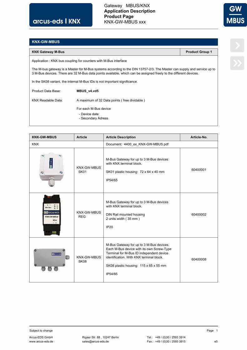
Application : KNX bus coupling for counters with M-Bus interface
The M-bus gateway is a Master for M-Bus systems according to the DIN 13757-2/3. The Master can supply and service up to3 M-Bus devices. There are 32 M-Bus data points available, which can be assigned freely to the different devices.
In the SK08 variant, the internal M-Bus IDs is not important significance.
Product Data Base: MBUS_v4.vd5
KNX Readable Data: A maximum of 32 Data points ( free dividable )
For each M-Bus device
- Device date- Secondary Adress
KNX-GW-MBUS Article Article Description Article-No.
KNX Document: 4400_ex_KNX-GW-MBUS.pdf
KNX-GW-MBUS SK01
M-Bus Gateway for up to 3 M-Bus deviceswith KNX terminal block.
SK01 plastic housing: 72 x 64 x 40 mm
IP54/65
60400001
KNX-GW-MBUS REG
M-Bus Gateway for up to 3 M-Bus deviceswith KNX terminal block.
DIN Rail mounted housing2 units width ( 35 mm )
IP20
60400002
KNX-GW-MBUS SK08
M-Bus Gateway for up to 3 M-Bus devices.Each M-Bus device with its own Screw-Type Terminal for M-Bus ID independent device identification. With KNX terminal block.
SK08 plastic housing: 115 x 65 x 55 mm
IP54/65
60400008
Arcus-EDS GmbH Rigaer Str. 88 , 10247 Berlin Tel.: +49 / (0)30 / 2593 3914
www.arcus-eds.de x [email protected] Fax.: +49 / (0)30 / 2593 3915 e5
Subject to change Page 1

arcus-eds I KNX
GW
MBUS
Gateway MBUS/KNX
Application DescriptionKNX-GW-MBUS xxx
Seite 2
›
‹
»«
1 Application Description
The M-Bus Gateway is set up using the ETS ( KNX Tool Software ) with the associated application program.The device is delivered unprogrammed.All functions are parameterized and programmed by ETS.
Functions
• 32 Data points for - Consumption values - Measured values - Date - Time
• 3 Data points for secondary address of the connected devices• 3 Data points for date information of the connected devices• 3 Data points for triggering special functions• 1 Data point for status information• 1 Data point to set the MBUS ID of the connected devices ( SK01 und REG )
2 KNX Parameter
1. Application Description 2 5. Product Page 8
2. KNX Parameter 2 6. Technical Data 9
3. KNX Objects 6 7. Startup 10
4. Function Description 7 8. Assembly 11
Imprint
2.1. Global Settings 3
2.2. MBus ID X 4 2.3. MBus Datapoint X 5
Arcus-EDS GmbH Rigaer Str. 88 , 10247 Berlin Tel.: +49 / (0)30 / 2593 3914
www.arcus-eds.de x [email protected] Fax.: +49 / (0)30 / 2593 3915 e5
Subject to change Page 2

arcus-eds I KNX
GW
MBUS
Gateway MBUS/KNX
Application DescriptionKNX-GW-MBUS xxx
Seite 3
›
‹
»«
2.1 Global Settings
Global Settings - KNX-GW-MBUS xxx
Parameter Setting Description
KNX Sending Cycle None1 min .. 12 h
The measured values are sent a measurement change independently in the cycle time.
NKE NoYes
If set to “Yes”, SND-NKE command before each M-Bus read cycle is sent.
Baudrate 30024009600
The baud rate with which communicates via the M-Bus must match the setting of the M-Bus slaves.2400 baud is the default value.
Only at SK01 and REG
MBus-Devices Single Device3 ID‘s
This setting determines whether only one M-Bus device is operated or up to three devices.With just one device simplifies the parameterization, since the identification runs via the broadcast address 254.
The ID can be programmed via an object.For details, see 4. Function Description.
Arcus-EDS GmbH Rigaer Str. 88 , 10247 Berlin Tel.: +49 / (0)30 / 2593 3914
www.arcus-eds.de x [email protected] Fax.: +49 / (0)30 / 2593 3915 e5
Subject to change Page 3

arcus-eds I KNX
GW
MBUS
Gateway MBUS/KNX
Application DescriptionKNX-GW-MBUS xxx
Seite 4
›
‹
»«
2.2 MBus ID X
MBus ID X - KNX-GW-MBUS xxx
Parameter Setting Description
MBus-ID X 0 .. 250 Each M-Bus device is accessed by a unique ID. This must match the ID stored in the device. The preset value is stated in general on the device. If only one device, eliminating the ID setting.
The ID can be programmed via an object.
The SK01 and REG variant eliminates these parameters,if settingGlobal SettingsParameter “MBus-Devices = Single Device“
When using the SK08 variation of these parameters is eliminated.
For details, see 4. Function Description.
Read Cycle 10 sec .. 12 h Many M-Bus devices allow only a limited number of readings per day or a minimum readout cycle.This applies preferably for battery holder devices, but should be requested in each case from the meter manufacturer.The read cycle is adjusted accordingly.
Attention:If the M-Bus read cycle is equal to the KNX sending cycle, it may happen that after two cycles of setting the values, a change in the value can be seen on the KNX bus.
Device Date Identifier 8 Character Data Information Field [DIF(E)] andValue Information Field [VIF(E)] of the device date of the M-Bus device can be specified as hexadecimal values.
Special Function Identifier 32 Character Some M-Bus devices support special functions such as reset a utility meter. The string can be specified as a string of hexadecimal values here.
Arcus-EDS GmbH Rigaer Str. 88 , 10247 Berlin Tel.: +49 / (0)30 / 2593 3914
www.arcus-eds.de x [email protected] Fax.: +49 / (0)30 / 2593 3915 e5
Subject to change Page 4

arcus-eds I KNX
GW
MBUS
Gateway MBUS/KNX
Application DescriptionKNX-GW-MBUS xxx
Seite 5
›
‹
»«
2.3 MBus Datapoint X
MBus Datapoint X - KNX-GW-MBUS xxx
Parameter Setting Description
Send on change NoYes
If "Yes", the M-Bus data point is sent when the value changes.
Send cyclical NoYes
If "Yes", the M-Bus data point value of a value change is independent as underGlobal SettingsParameter “KNX Sending Cycle“is sent.
ID Select NoneID1 - ID3
Assignment of the data point to a M-Bus device
MBus DPT Identifier String,up to 8 hex-character
Data Information Field [DIF(E)] andValue Information Field [VIF(E)] of the data point can be specified as hexadecimal values ( see manufacturers datasheet ).
The HEX characters must be specified in succession without spaces or other characters.see 4. Function Description
KNX DPT Type 6 Byte Metering Value4 Byte Float4-Byte unsigned IntegerDateTime
Adjustment Value Powers of ten of10^-6 ... 10^6
With adjustment value, the value representation can be customized in the ETS (decimal point).
Comment up to 64 ASCII-character The comment uses as an overview in the parameterization.
Arcus-EDS GmbH Rigaer Str. 88 , 10247 Berlin Tel.: +49 / (0)30 / 2593 3914
www.arcus-eds.de x [email protected] Fax.: +49 / (0)30 / 2593 3915 e5
Subject to change Page 5

arcus-eds I KNX
GW
MBUS
Gateway MBUS/KNX
Application DescriptionKNX-GW-MBUS xxx
Seite 6
›
‹
»«
3 KNX Objects
Objects - KNX-GW-MBUS xxx
No. Label Data Point Type Function
0:
..31
Output, Value x DPT 4 Byte MBus Value
0:
..31
Output, Date x DPT 3 Byte MBus Date
0:
..31
Output, Time x DPT 3 Byte MBus Time
323436
Output, Secondary Address Device x DPT 16.000 14 Byte Secondary Address
333537
Output, Date Device x DPT 10.001 3 Byte Device Date
38 IO, ID programming DPT 5.* 1 Byte ID programming
39 Output, Status DPT 5.* 1 Byte Status
404142
Input, Special Function ID x DPT 1.010 1 Bit SendSpecial Function
Object Description - KNX-GW-MBUS xxx
Object Description
Output, Value x The value of a data point
Output, Date x Date ( for example, be used as a date stamp )
Output, Time x Time ( for example, be used as a time stamp )
Output,Secondary Address Device x
The serial numbers of M-Bus devices.
Output, Date Device x The internal Date of M-Bus devices.
IO, ID programming Using this object, the connected device must have an ID assigned.
Output, Status Status value = 0 : M-Bus ok, not any device is connected or detected.Status value = 1 : M-Bus ok, one device is connected or detected.Status value = 2 : M-Bus ok, two devices are connected or detected.Status value = 3 : M-Bus ok, three devices are connected or detected.Bit 3 (decimal 8) corresponds to a short circuit (fault) in the M-Bus line.
Input,Special Function ID x
When writing a 1 to this object, the special function is executed.Please note the information about the meter manufacturer!
Arcus-EDS GmbH Rigaer Str. 88 , 10247 Berlin Tel.: +49 / (0)30 / 2593 3914
www.arcus-eds.de x [email protected] Fax.: +49 / (0)30 / 2593 3915 e5
Subject to change Page 6

arcus-eds I KNX
GW
MBUS
Gateway MBUS/KNX
Application DescriptionKNX-GW-MBUS xxx
Seite 7
›
‹
»«
4 Function Description
The M-Bus was developed for configuration and reading of data from meters and consumption counting devices. The M-Bus is a bus with a single master that powers and reads out multiple slave devices. Each slave is addressable with an individual ID that is between 1 and 250. Theoretically up to 250 slave devices could be operated in one M-Bus segment, but the practical number is determined by the ability of the master to power the devices. The topology is not critical and no termination is required. Maximum bus length is 4km in theory depending on the baudrate, in practical situations not more than 10m should be aspired for good noise immunity.
The SK01 / REG variants from Gateway can power up to 3 devices and communicate with them. If only one device is present, this can be addressed independent of its individual ID with the broadcast ID ( 254 ). This simplifies the configuration of such a minimal system.
When used the SK08 variant all connected devices are addressed via a broadcast ID.An importance of IDs eliminates.
Some M-Bus devices can be powered through the M-Bus, others draw current from the internal battery at readout of the data. So some M-Bus devices only allow a certain number of readings over an amount of time to disburden the internal batteries. The readout cycles must be choosen accordingly.
Readout of the devices data is initiated by the master by sending a REQ_UD2 ( Request User Data ) telegram. The connected devices check if they are addressed by comparing their ID and return a RSP_UD ( Respond User Data ) telegram. The RSP_UD telegram contains up to 252 byte of user data. The user data consists of several data packages each of them beginning with some identification bytes, the DIF ( Data Information Field ) and the VIF ( Value Information Field ). DIF and VIF can have several byte, of practical relevance are 1 or 2 byte per field. With 4 byte nearly all data packages can be identified. If a value field represents a reference value there is usually a date field associated with this value. The information that can be expected in the DIF and VIF are different with every manufacturer and every device class. Generally the desired informations can be achieved from the manufacturers. The values for the DIF and VIF must be identified and written into the appropriate fields as strings of hexadecimal characters.
Examples
Water meterVolume information DIF 04 VIF 13 Data to write into the parameter field: 0413Reference value DIF 04 VIF 80 13 Data to write into the parameter field: 048013
Electrical MeterTotal consumption DIF 04 VIF 03 Data to write into the parameter field: 0403Actual consumption DIF 02 VIF 2B Data to write into the parameter field: 022B
These are examples only, the correct data sequences can be obtained from the manufacturer of the counters/meters.Some meters provide extra functionalty as resettable counters or minimum/maximum values that can be reset with special data sequences. These sequences can be defined in the ETS and can be triggered by writing a "1" on an Object.
Set the ID of a connected device:
1) Select under "Global Settings", parameter "MBus-Devices" = "Single Device"2) The Object "IO, ID programming" is active3) Connecting the device and send desired ID (1 .. 250) on the object "IO, ID programming"
The status value bits:
Status value = 0 : M-Bus ok, not any device is connected or detected.Status value = 1 : M-Bus ok, one device is connected or detected.Status value = 2 : M-Bus ok, two devices are connected or detected.Status value = 3 : M-Bus ok, three devices are connected or detected.Status value = 8 : The M-Bus is shorted or overloaded.
Arcus-EDS GmbH Rigaer Str. 88 , 10247 Berlin Tel.: +49 / (0)30 / 2593 3914
www.arcus-eds.de x [email protected] Fax.: +49 / (0)30 / 2593 3915 e5
Subject to change Page 7

arcus-eds I KNX
GW
MBUS
Gateway MBUS/KNX
Product PageKNX-GW-MBUS xxx
Seite 8
›
‹
»«
5 Product Page
The KNX-GW-MBUS xxx is a device that can integrate all kind of consumption measuring devices that are equipped with an M-Bus interface into the KNX-bus.
Up to 3 M-Bus devices can be supplied and up to 32 data point values can be collected and sent to the KNX-Bus. Each of these Datapoints can have a date associated in case of reference values.
The device has an integrated bus coupling unit and needs no auxiliary power.
The KNX-GW-MBUS SK01 is delivered in a housing of an impact resistant glass pallet reinforced plastic with gasket and achieves the protection class IP54/65.
The KNX-GW-MBUS REG is delivered in a housing of fire retardent plastic meant for DIN rail mounting and achieves the protection class IP20.
The KNX-GW-MBUS SK08 is delivered in a high-strength, extremely robust stable impact ABS plastic housing. Cover and base have a revolving groove and tongue system with neoprene gasket and achieves the protection class IP54/65.
The KNX-GW-MBUS is set up using the ETS ( KNX Tool Software ) and the applicable application program.
Applications
• Integration of Meters and Consumption counters into the KNX-bus• Acquisition and communication of consumption data in KNX
environments• Retrofitting of existing M-Bus installations
Articel-No.: 6040000x
KNX-GW-MBUS xxxSK01 und SK08 IP54/65
REG IP20
Arcus-EDS GmbH Rigaer Str. 88 , 10247 Berlin Tel.: +49 / (0)30 / 2593 3914
www.arcus-eds.de x [email protected] Fax.: +49 / (0)30 / 2593 3915 e5
Subject to change Page 8
arcus-eds I KNX
GW
MBUS
Gateway MBUS/KNX
Product PageKNX-GW-MBUS xxx
Seite 9
›
‹
»«
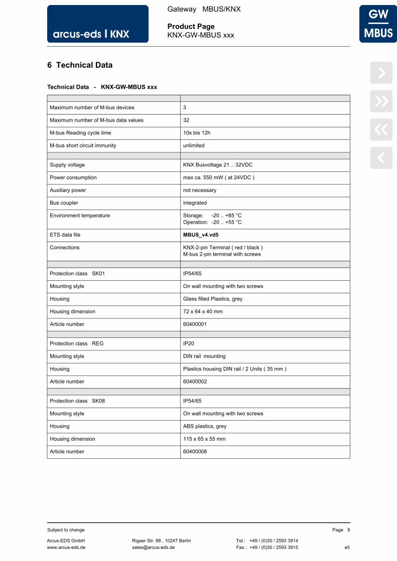
6 Technical Data
Technical Data - KNX-GW-MBUS xxx
Maximum number of M-bus devices 3
Maximum number of M-bus data values 32
M-bus Reading cycle time 10s bis 12h
M-bus short circuit immunity unlimited
Supply voltage KNX Busvoltage 21 .. 32VDC
Power consumption max ca. 550 mW ( at 24VDC )
Auxiliary power not necessary
Bus coupler integrated
Environment temperature Storage: -20 .. +85 °COperation: -20 .. +55 °C
ETS data file MBUS_v4.vd5
Connections KNX-2-pin Terminal ( red / black )M-bus 2-pin terminal with screws
Protection class SK01 IP54/65
Mounting style On wall mounting with two screws
Housing Glass filled Plastics, grey
Housing dimension 72 x 64 x 40 mm
Article number 60400001
Protection class REG IP20
Mounting style DIN rail mounting
Housing Plastics housing DIN rail / 2 Units ( 35 mm )
Article number 60400002
Protection class SK08 IP54/65
Mounting style On wall mounting with two screws
Housing ABS plastics, grey
Housing dimension 115 x 65 x 55 mm
Article number 60400008
Arcus-EDS GmbH Rigaer Str. 88 , 10247 Berlin Tel.: +49 / (0)30 / 2593 3914
www.arcus-eds.de x [email protected] Fax.: +49 / (0)30 / 2593 3915 e5
Subject to change Page 9

arcus-eds I KNX
GW
MBUS
Gateway MBUS/KNX
Product PageKNX-GW-MBUS xxx
Seite 10
›
‹
»«
7 Startup
The KNX-GW-MBUS is set up using the ETS ( KNX Tool Software ) and the applicable application program.The gateway is delivered unprogrammed.All functions are programmed and parameterized with ETS.Please read the ETS instructions.
KNX-GW-MBUS SK01 / KNX-GW-MBUS REG Assembly View
Programming ButtonLED
KNXTerminalblock
M-BUSScrew-Type Terminal
Programming ButtonLED
M-BUSScrew-Type Terminal
KNXTerminalblock
KNX-GW-MBUS SK08 Assembly View
M-BUSScrew-Type Terminal
Programming ButtonLED
3 2 1 M-BUS Device Connector
KNXTerminalblock
Arcus-EDS GmbH Rigaer Str. 88 , 10247 Berlin Tel.: +49 / (0)30 / 2593 3914
www.arcus-eds.de x [email protected] Fax.: +49 / (0)30 / 2593 3915 e5
Subject to change Page 10

arcus-eds I KNX
GW
MBUS
Gateway MBUS/KNX
Product PageKNX-GW-MBUS xxx
Seite 11
›
‹
»«
8 Assembly
The KNX-GW-MBUS SK01 device is intended for mounting in indoor/outdoor and damp room environment.It achieves the protection class IP54/65.Mounting is done on wall through 2 screw holes.
The cover of the device can be removed by turning the screws on the top.Feed the KNX-bus cable through the fitting into the device after mounting the gateway on the wall or ceilling. For this you must remove the connector block from the cable, after insertion the connector block can be attached again. After successfull programming the cover should be mounted again.Be careful not to damage the electronics with tools and cable heads.
The KNX-GW-MBUS REG device is intended for DIN rail mounting in dry indoor environment. Mountig is done by clipping the device on the DIN rail. Protection class IP20 is achieved.
The KNX-GW-MBUS SK08 device is intended for mounting in indoor/outdoor and damp room environment.It achieves the protection class IP54/65.Mounting is done on wall through 2 screw holes.
In Case of Bus Voltage Recurrence
The values of M-Bus devices are available again after a new reading.The ETS parameter settings are retained.
Discharge Program and Reset Sensor
In order to delete the programming ( projecting ) and to reset the module back to delivery status, it must be switched to zero potential ( disconnect the KNX bus coupler ).Press and hold the programming button while reconnecting the KNX-bus coupler and wait until the programming LEDlights up ( approx. 5-10 seconds ).Now you can release the programming button.The module is ready for renewed projecting.If you release the programming button too early, repeat the aforementioned procedure.
Arcus-EDS GmbH Rigaer Str. 88 , 10247 Berlin Tel.: +49 / (0)30 / 2593 3914
www.arcus-eds.de x [email protected] Fax.: +49 / (0)30 / 2593 3915 e5
Subject to change Page 11

arcus-eds I KNX
Seite 12
‹«
Imprint
Editor: Arcus-EDS GmbH, Rigaer Str. 88, 10247 BerlinResponsible for the contents: Hjalmar Hevers, Reinhard PegelowReprinting in part or in whole is only permitted with the prior permission of Arcus-EDS GmbH.All information is supplied without liability. Technical specifications and prices can be subject to change.
Liability
The choice of the devices and the assessment of their suitability for a specified purpose lie solely in the responsability of the buyer. Arcus-EDS does not take any liability or warranty for their suitability. Product specifications in catalogues and data sheets do not represent the assurance of certain properties, but derive from experience values and measurements. A liability of Arcus-EDS for damages caused by incorrect operation/projecting or malfunction of devices is excluded. The operator/project developer has to make sure that incorrect operation, planning errors and malfunctions cannot cause subsequent damages.
Safety Regulations
Attention! Installation and mounting must be carried out by a qualified electrician.The buyer/operator of the facility has to make sure that all relevant safety regulations, issued by VDE, TÜV and the responsible energy suppliers are respected. There is no warranty for defects and damages caused by improper use of the devices or by non-compliance with the operating manuals.
Warranty
We take over guarantees as required by law.Please contact us if malfunctions occur. In this case, please send the device including a description of the error to the company's address named below.
Manufacturer
Registered Trademarks
The CE trademark is a curb market sign that exclusively directs to autorities and does not include any assurance of product properties.
Registered trademark of the Konnex Association.
Arcus-EDS GmbH Rigaer Str. 88 , 10247 Berlin Tel.: +49 / (0)30 / 2593 3914
www.arcus-eds.de x [email protected] Fax.: +49 / (0)30 / 2593 3915
Subject to change


![Arcus: The X-ray Grating Spectrometer Explorerarcusxray.org/Arcus-SPIE2017-submitted.pdf3 3. SCIENCE The Arcus science case [8] covers a range of questions raised in the 2010 Decadal](https://static.fdocuments.us/doc/165x107/6023a4518149413a5578841a/arcus-the-x-ray-grating-spectrometer-3-3-science-the-arcus-science-case-8-covers.jpg)