4281 4285.output
58
* GB784688 (A) Description: GB784688 (A) ? 1957-10-16 A machine for applying rubber or like caps to goods containers Description of GB784688 (A) PATENT SPECIFICATION Inventor: CHIARLES ERIC MTILNER Zt SJJ Date of filing Complete Specification April 6, 1956. l/l '/\F Application Date April 30, 1955 No I ; i Complete Specification Published Oct 16, 1957. Index at acceptance: -Classes 108 ( 3), R;,and 125 ( 2), E 3 (B 2 C: Dl)o International Classification: -B 67 b. COMPLETE SPECIFICA TION A Machine for Applying Rubber or like Caps to Goods Containers We, B Eg TON & STONE LIMITED, of Aston I 3 rook Street, in the City of Birmingham, 6, a British Company, do hereby declare the invention for which we pray that a patent may be granted to us, and the method by which it is to be performed to be particularly described in and by the following statement: - This invention has for its object to provide in a convenient form, a
-
Upload
j1075017 -
Category
Government & Nonprofit
-
view
65 -
download
0
Transcript of 4281 4285.output
* GB784688 (A)
Description: GB784688 (A) ? 1957-10-16
A machine for applying rubber or like caps to goods containers
Description of GB784688 (A)
PATENT SPECIFICATION Inventor: CHIARLES ERIC MTILNER Zt SJJ Date of filing Complete Specification April 6, 1956. l/l '/\F Application Date April 30, 1955 No I ; i Complete Specification Published Oct 16, 1957. Index at acceptance: -Classes 108 ( 3), R;,and 125 ( 2), E 3 (B 2 C: Dl)o International Classification: -B 67 b. COMPLETE SPECIFICA TION A Machine for Applying Rubber or like Caps to Goods Containers We, B Eg TON & STONE LIMITED, of Aston I 3 rook Street, in the City of Birmingham, 6, a British Company, do hereby declare the invention for which we pray that a patent may be granted to us, and the method by which it is to be performed to be particularly described in and by the following statement: - This invention has for its object to provide in a convenient form, a nmachine for applying caps made from rubber or like extensible material to cartons, bottles or other goods containers. A machine in accordance with the invention comprises the combination of a plurality of fingers arranged in annular form and on the tips of which a cap can be placed, a corresponding number of fluid-operable plungers for imparting radial movements to the fingers, and means for effecting relative axial movemehts of the container and fingers. In P articular the invention comprises a machine having the features specified in the preceding paragraph, in combination withl an intermittently movable rotary table for carryikg the containers, a relatively slidable head carrying the fingers and their actuating means, and a fluidoperable plunger for actuating thehead. In the accompanying drawings, Figure 1 is a front elevation of a machine embodying the invention. Figure 2 is a sectional plan of the machine on the line 1 1 of Figure 1, and Figure 8 is a sectional front elevation of the part of tbe
machine provided with the cap-extending fingers, Figures 2 and 3 being drawn to a larger scale than Figure 1. Referring to the drawings, the machine there shown comprises a bed a, a pair of vertical pillars b e xtending from the bed, a fixed head c at the upper ends of the pillars, a slidable head d carried by the lPri 784 A 688 12600/55. pillars between the fixed head and the bed, and a rotary table e supported on the bed concentrically with one of the pillars, the table being provided with sockets f into which the lower ends of the containers 50 can be inserted. On the upper side of the fixed head e is centrally secured a vertical cylinder g containing a double-acting piston from which extends a rod h attached to the 55 slidable head d The motive fluid employed for actuating this piston (and the other pistons to be hereafter described) is preferably compressed air and on the fixed head is mounted any convenient valve (not 60 shown) for controlling the admission and discharge of air to and from each end of the cylinder. To the slidable head is secured by means of posts i j a ring k made from two 65 similar rings placed in contact with each other In one or each of the contiguous faces of the rings are formed a pair of annular passages m N (Figure 2) for conveying motive air to the cylinders to be 70 hereinafter described, and these passages are isolated from each other by sealing rings o (Figure 3) The two posts i serve only to attach the ring k to the slidable head, but the two posts j are hollow and 75 serve also to convey motive air to the said annular passages m n To each post j is secured a pipe p which is telescopically slidable in a pipe q secured to the fixed head c and each pipe q is connected by a 80 pipe r to any convenient valve (not shown) for controlling the flow of air to and from the ring passages m n. At the underside of the ring k are arranged a number of iadially mounted 85 cylinders S each containing a double acting piston t from which extends a rod v. To the outer end of each rod is secured a finger v, and the arrangement of the fingers is su, ch that 90 784,688 they are disposed in annular form around the central vertical axis of the rings with their tips uppermost Preferably each finger has combined with its lower end a horizontal guide rod W which is parallel with the associated piston rod and is supported by a guide lug x on the underside of the associated cylinder Also the ing is provided with a pair of slippers y which partially embrace the pillars b and serve to hold the ring centrally between the pillars. Between the ring k and the table e are mounted a pair of grippers 2 for gripping the container 10 to which the cap 3 (Figure 3) is to be attached, the grippers being carried by piston rods 4 extending from
pistons contained in a pair of cylinders 5 carried by the pillars b, the purpose of the grippers being to centralise the container with respect to the vertical axis of the fingers, and hold it when the cap is being applied Air for the gripper cylinders is controlled by any convenient valve 6 mounted on the bed a. The valve 6 associated with the grippers is actuated by a lever 7 mounted on the bed a and which at one end carries a roller 8 in contact with the periphery of the table In this perip Lery are formedl notches 9 which can be successively occupied by the roller 8 only when a container is in its proper position. In each cycle of operations, the attendant places a container 10 into each in turn of the sockets f on the table, and then first actuates the lever 7 for disengaging the roller 8 from the table The effect of this movement of the lever is to epen the associated valve 6, so enabling the air admitted to the gripper cylinders to retract the grippers The attendant then turns the table by hand to bring the cohtainer to the cap-applying position. Release of the lever allows it to return for engaging the roller with the adjacent notch in the table, and by this movement the valve 6 causes the grippers to be released so that they can move into contact with the container under the action of springs contained in the gripper cylinders Also the attendant applies a cap 3 to the fingers The attendant then actuates the valve which admits air to the finger cylinders whereupon the fingers ara all simultaneously moved outwardly for stretching the cap to a larger diameter than the upper end of the container 'Subsequently another valve is actuated for 0 admitting air to the cylinder,q causihg the head d to lower the ring k for dep)ositing the cap on the container Continued downward movement of the head causes the fingers to leave the cap, whereupon the cap contracts on the upper end of the 65 container Whilst the fingers are still extended, the head is theb returned to its upper position, and on reaching this position the fingers are returned to their contracted position for reception of the cap 70 to be attached to the next container. The various valves which control the movements of the slidable head and fingers are inter-related by any convenient means for ensuring the actuation in the desired 75 sequence in each cycle.
* Sitemap * Accessibility * Legal notice * Terms of use * Last updated: 08.04.2015 * Worldwide Database
* 5.8.23.4; 93p
* GB784689 (A)
Description: GB784689 (A) ? 1957-10-16
Improvements in or relating to comb-type band-pass filters
Description of GB784689 (A)
PATENT SPECIFICATION 7846859 Date of Application and filing Complete Specification: June 3, 1955. No 16029/55. Application made in France on June 3, 1954. Complete Specification Published: Oct 16, 1957. Index at acceptance:-Class 40 ( 8), Y( 1: 6). International Classification:-HO 3 h. COMPLETE SPECIFICATION Improvements in or relating to Comb-Type Band-Pass Filters We, COMPAGNIE GENERALE DE TELEGRAPHIE SA Ns Fi L, a French Body Corporate, of 79, Boulevard Haussmann, Paris, France, do hereby declare the invention, for which we pray that a patent may be granted to us, and the method by which it is to be performed, to be particularly described in and by the following statement: - The present invention relates to band-pass filters of the so-called "comb type," that is to say filters with a transmssion characteristic which is a function of frequency and the curve of which is in tooth form with equally spaced teeth More specifically the invention relates to filters of this type wherein the input and output circuits are coupled by the magnetostrictive effect respectively to two magnetostrictive portions of a bar which is thus made the seat of mechanical oscillations, of the same frequency as the electrical oscillations applied thereto through the input circuit As is well known, the fundamental harmonic frequencies of this bar correspond respectively to the frequencies of successive teeth of the filter transmission characteristic curve. The resonance frequency of a bar is a function of the length of the bar and of the propagation velocity of the mechanical oscillations in
the bar A disadvantage of known filters which use longitudinal oscillations is that they are too long to meet the requirements existing in certain applications. It is an object of the present invention to provide a magnetostrictive comb-type filter having good filtering characteristics while avoiding the above disadvantage of excessive length. In the filter according to the invention, the magnetostrictive input and output portions are twisted or torsioned, beyond the elastic limit of the material of which they are constituted, through an angle sufficient to ensure that substantial torsional oscillations arise together with the longitudinal oscillations due to magnetostrictive effect Two clamping arrangements are respectively provided at the two ends of the bar, outwardly with respect to the lPrice 3 s 6 d l magnetostrictive portions of the bar, in order to constitute obstacles which reflect torsional oscillations while passing longitudinal oscillations which are then absorbed. The invention will be better understood from the following description and appended drawing, wherein: Fig 1 shows very diagrammatically a bar filter in accordance with the invention; Fig 2 shows, in elevation, the twisted portion of the bar of Fig 1; Fig 3 is a modification of Fig 2; Fig 4 shows, to a larger scale, an embodiment of one end of the arrangement shown in Fig 1; Fig 5 is a section along V-V of Fig 4; Fig 6 shows the transmission characteristic of a filter according to the invention. The filter shown in Fig 1 comprises an input circuit 4 and an output circuit 5, magnetostrictively coupled respectively through windings 3 and 31, to two magnetostrictive portions 1 and 1 ' of a bar 2 At either end of this bar, beyond portions 1 and 11, there is provided a reflective means, for example a clamping device 6, or 6 ', so arranged that the clamped zones of the bar form obstacles which reflect the torsional oscillations of the bar, but which pass the longitudinal oscillations without reflection. Figs 4 and 5 show an embodiment of the clamping device It comprises a support 21 and a cap 23, between which are respectively inserted jaws 26 and 27 These jaws are provided with mating notches 29 and 30 having the shape of the bar 2 Thus the bar is securely clamped, when screws 24 are tightened The thickness e of jaws 26 and 27 is very small compared with the wavelength corresponding to the resonance frequency of the bar In this way, the jaws present substantially no obstacle to the propagation of the longitudinal oscillations along the bar Of course, the bar must withstand the crushing pressure exerted by the clamps As an example, treated steel jaws should have a thickness of 1 mm or of a few tenths of millimetre in most cases. 7 G In order to absorb longitudinal oscillations propagating in the
bar 2, absorptive means is provided, for example in the form of two sleeves 7 and 71 made of a material having considerable internal friction, such as rubber, as shown in Figs 1 and 3 They are in close contact with the bar at either end thereof, outwardly with respect to the clamping devices 6 and 6 '. The bar 2 is firmly held at its two ends by means of clamping arrangements 8 and 8 '. At least one of these arrangements comprises means for tensioning the bar 2 These means may comprise for instance a support 11 in which is slidably mounted an internally threaded holder 12, wherein a knob 13 is screwed A groove 14 is provided on the outer surface of the holder 12 and a stud 15, which prevents the latter from rotating, penetrates in this groove The bar is clamped between a concave portion of the holder 12 and a mating portion 16, secured thereto by means of two screws 17. It is obvious that by rotating the knob the holder 12 is slidably moved on the support 11 and the tension of the bar 2 is regulated. The two arrangements 8 and 81 are secured to a base 18 Clamping devices 6 and 61 are also secured to the base 18 The winding 3 is provided with a magnetic yoke 9 and a screen and assembly 3, 9, 10 is secured to clamp 6 Winding 31 is similarly mounted with respect to clamp 61 The magnetic circuits of windings 3 and 31 are respectively completed by portions 1 and 1 ' of the bar 2. In accordance with the invention, portions 1 and 11 are twisted, beyond the elastic limit of the material of which they are made, through an angle sufficient to ensure that substantial torsional oscillations occur together with longitudinal oscillations resulting from magnetostriction in those portions and conversely Fig 2 shows the twisted portion 1 of a bar 2 of circular section The portion 1 is limited by sections a and b Any generatrix, which initially was parallel to the bar axis, follows, once the bar has been subjected to torsion, a substantially helical line C The length of the twisted portion 1 and the angle of torsion are not critical Preferably, the twisted portion of the bar 2 should be contained within the excitation zone of winding 3, and its length should be nearly equal to the thickness of the latter, which thickness should moreover be kept as small as possible, in order that the resonance conditions of the bar shall be fulfilled for harmonic frequencies of high order As an example, with a bar 2 mm in diameter, good results have been obtained with a twisted portion 1 about 15 mm long, the angle of torsion being of the order of 450. Fig 3 shows twisted portion 1 of a bar of rectangular section. Whether bar 2 be circular, rectangular or any other section, experience shows that longitudinal oscillations occurring in the
twisted portion 1 generate torsional oscillations and conversely The bar 2 used in the filter of the invention must be such that its torsional resonant frequency is equal to the fundamental 70 frequency of the pulses applied to the input 4 of the filter How a bar must be chosen to have a given resonant torsional frequency is well known in the art. The operation of the filter described is as 75 follows: when electrical pulses of a frequency F are applied to the input circuit 4, the winding 3 is the seat of electrical oscillations of frequencies F, 2 F, 3 F, 4 F-n F Through magnetostrictive effect these electrical oscilla 80 tions produce in the twisted portion 1 of the bar 2 longitudinal mechanical oscillations at those same frequencies These longitudinal mechanical oscillations are propagated along the bar on either side of portion 1; they 85 traverse without appreciable reflection the obstacles respectively presented by the clamps 6 and 6 ' and are absorbed by the damping sleeves 7 and 71 As already pointed out, torsional mechanical oscillations of frequencies 90 F, 2 F, 3 F-n F are generated at the same time. They are also propagated along the bar, but are completely or substantially reflected by the clamps 6 and 6 '. In these conditions, stationary torsional 95 waves are generated in the bar 2 Since the bar, as a whole, is so selected that it is in torsional mechanical resonance for the fundamental frequency F, the torsional oscillations generated in the twisted portion 1, whose fre 100 quencies are F, 2 F, 3 F-n F, put the bar in torsional mechanical resonance, and the mechanical oscillations thus produced have much higher amplitudes than those generated in portion 1 and from which they originate The 105 torsional mechanical oscillations resulting from the resonance of the bar generate, in the twisted part of the bar, longitudinal oscillations having the same frequencies, and these longitudinal oscillations generate, by magneto 110 strictive effect, electrical oscillations of the same frequencies in the output winding 31. The circuit 5 thus becomes the seat of pulses with recurrence frequency F. The transmission characteristics of the filter 115 under consideration has the form shown in figure 6, for the case where F= 500 cycles per second; plotted as abscissa are the values in kilocycles per second of the transmitted frequencies f, and as ordinates the corresponding 120 values of the transmission coefficient T. Thus, the operation of the filter according to the invention is based on the resonance of torsional mechanical oscillations The bar may accordingly be much shorter than in known 125 filters wherein use is made of the resonance of longitudinal mechanical oscillations, since
the velocity Vt of propagation in the bar of torsional oscillations is less than the velocity V, of longitudinal oscillations For example, 130 784,689 shaped characteristic is obtained. It will be noted that by operating as set forth above, clamps 6 and 61 are tightened 60 only after the bar has been put under tension. As a result, the tension of the bar is taken up only by the fixing devices 8 and 81, and the jaws 26 and 27 of each clamp 6 and 6 ' are not subjected to lateral stresses 65 The thickness of these jaws can thus be reduced to a minimum, and no longitudinal shift of the bar at the clamped zones need be expected. The bar 2 may be constructed entirely of a 70 magnetostrictive metal such as nickel, or of an alloy so selected as to possess, in addition, propagation characteristics which are independent of temperature The bar may also be provided with magnetostrictive portions 1 and 75 11 made, for example, of ferrite only near windings 3 and 31 The remainder of the bar is then of duraluminium. As in most arrangements utilising magnetostriction, it is preferable to polarize magnetic 80 ally the active parts of the bar This polarization may be provided either by means of an externally placed magnet or by an extra winding, or again, by passing a direct current through windings 3 and 31 85 Filters according to the invention possess characteristics of great interest In one example, employing a nickel bar 2 mm in diameter, setting the clamps 1,5 meters apart and using sleeves 7 and 7 ' of about 0,25 90 meters in length, it is possible to produce a filter operating on a fundamental frequency of 1,000 cycles per second, transmitting 200 harmonics, passing correctly 5 microsecond pulses and still giving satisfactory information 95 for 1 micro-second pulses, the improvement of the signal to noise ratio being, in this case, about 17 db. In another example having substantially the same operating characteristics, the nickel bar 100 had a rectangular section of 0,5 mm by 3 mm, the distance separating the two clamps was 0,46 meters, and the length of sleeves 7 and 7 ' was about 0,25 meter. The invention is not restricted to the 105 examples shown and described, and numerous modifications can be made without departing from the scope of the invention.
* Sitemap * Accessibility * Legal notice * Terms of use * Last updated: 08.04.2015 * Worldwide Database * 5.8.23.4; 93p
* GB784690 (A)
Description: GB784690 (A) ? 1957-10-16
Improvements in regulating devices for gas turbine engines operating bycontrolling the fuel supply thereto
Description of GB784690 (A)
PATENT SPECIFICATION Date of Application and filing Complete Specification: June 10, 1955. Application made in France on June 11, 1954. Complete Specification Published: Oct 16, 1957. 784,690 No 16802/55. Index at acceptance:-Classes 110 ( 3), C 1 OE( 1 B 3:1 B 4:2 A); and 135, P( 1 C:1 F:1 H:4:16 E 5: 21:24 KX:24 X:26). International Classification:-FO 2 c, CO 5 c. COMPLETE SPECIFICATION Improvements in Regulating Devices for Gas Turbine Engines operating by controlling the Fuel Supply thereto We, SOCIETE NATIONALE D'E Tu DE ET DE CONSTRUCTION DE MOTEURS D'Av IATION, a French Body Corporate, of 150 Boulevard Haussmann, Paris, France, do hereby declare the invention for which we pray that a patent may be granted to us, and the method by which it is to be performed, to be particularly described in and by the following statement:The present invention relates to an improvement in the regulation of turbo-jet units, turbo-propulsion units with a view to avoiding the extinction of such installations, and the mismatching thereof owing to surging of the air compressor There exist limit values for the two cases On the one hand, if the quantity of fuel injected falls below the limit corresponding to the delivery pressure of the compressor, the jet unit is extinguished, while on the other hand if the quantity of fuel becomes too great the compressor operates the under surging conditions and the jet unit becomes mismatched. According to the invention, the supply of fuel to the combustion equipment of a gasturbine engine is maintained within the limits corresponding respectively to extinction and mismatching of the engine
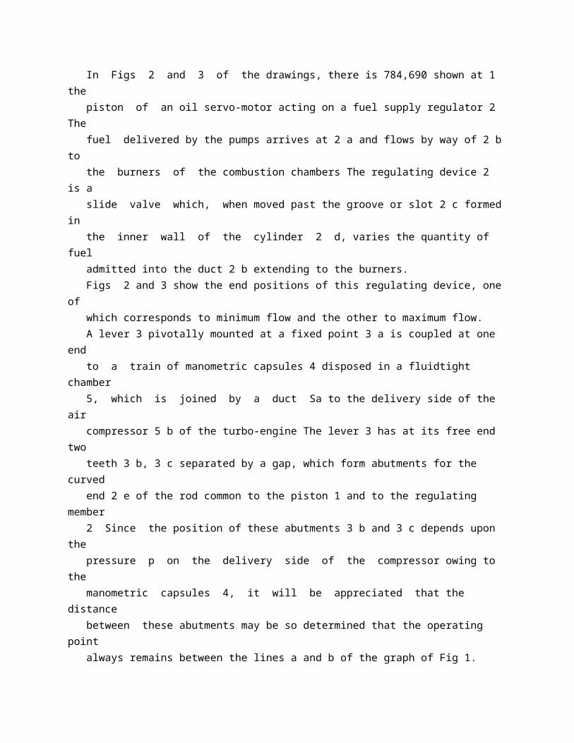
for every running condition thereof, by means of a regulating device comprising a member movable to control the fuel supply to the engine and associated with stops limiting the displacement of the said member in both directions so as to allow an acceleration up to the upper limit prescribed by the stop and similarly a retardation down to the lower limit, the position of the said stops being automatically adjusted in response to the delivery pressure of the compressor of the said engine. The invention is illustrated by way of example in the accompanying drawings in which: Fig 1 is an explanatory graph; Figs 2 and 3 show diagrammatically, in two different operating positions, a device illustrating the principle of the invention; lPrice 3/6 l Fig 4 illustrates a constructional form of a complete abutment device according to the invention; Figs 5 and 6 show the abutments in their 50 two end positions; Figs 7, 8 and 9 are graphs illustrating the operation of this device. The graph of Fig 1 has been drawn by plotting along the abscissae the pressure p 2 55 taken on the delivery side of the compressor of the turbo-unit and along the ordinates the flow of fuel C in litres per hour. The line a represents the variations of the C 60 limit ratio above which the turbo-engine P 2 becomes mismatched (excess of fuel) The line b represents similarly the variation of C the limit ratio below which the turboP 2 engine is extinguished (insufficient fuel). Finally, the curve c represents the normal operating characteristic of the turbo-engine 70 The turbo-engine must be controlled or regulated in such manner that the point representing operation corresponding to a pressure p 2 and to a flow C always remains between the lines a and b These lines may 75 be undesirably exceeded for various reasons, for example owing to excessively sudden movement of the lever controlling the regulation or the influence of atmospheric conditions at high altitudes or during high-speed 80 flight. Generally speaking, the known regulating devices affect two quantities, namely the speed of rotation of the turbo-engine and the temperature of the gases Since the opera 85 tion of a device according to 'the invention may be explained by considering only the regulation of the speed of rotation, no reference will be made in the following description of the regulating device to the members 90 affecting the temperature regulation. In Figs 2 and 3 of the drawings, there is 784,690 shown at 1 the piston of an oil servo-motor acting on a fuel supply regulator 2 The fuel delivered by the pumps arrives at 2 a and flows by way of 2 b to the burners of the combustion chambers The regulating device 2 is a slide valve which, when moved past the groove or slot 2 c formed in
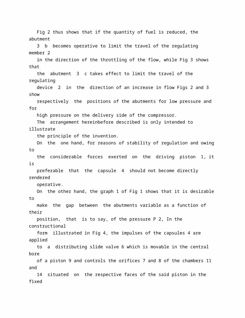
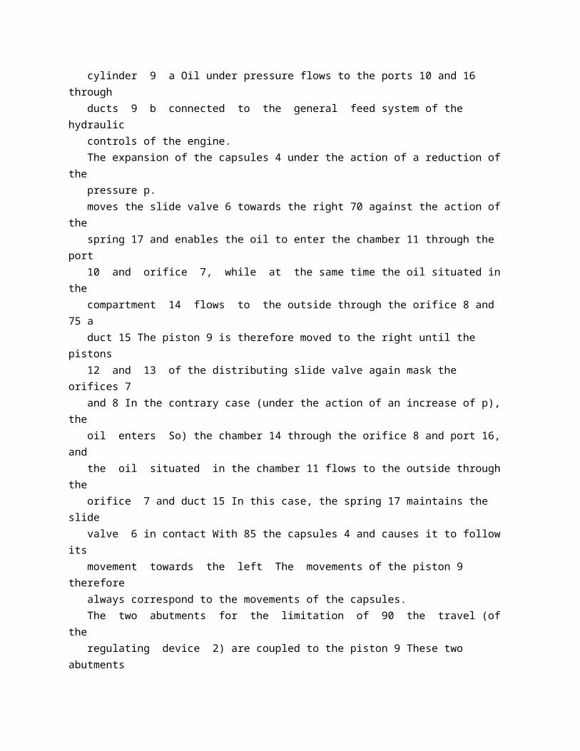
the inner wall of the cylinder 2 d, varies the quantity of fuel admitted into the duct 2 b extending to the burners. Figs 2 and 3 show the end positions of this regulating device, one of which corresponds to minimum flow and the other to maximum flow. A lever 3 pivotally mounted at a fixed point 3 a is coupled at one end to a train of manometric capsules 4 disposed in a fluidtight chamber 5, which is joined by a duct Sa to the delivery side of the air compressor 5 b of the turbo-engine The lever 3 has at its free end two teeth 3 b, 3 c separated by a gap, which form abutments for the curved end 2 e of the rod common to the piston 1 and to the regulating member 2 Since the position of these abutments 3 b and 3 c depends upon the pressure p on the delivery side of the compressor owing to the manometric capsules 4, it will be appreciated that the distance between these abutments may be so determined that the operating point always remains between the lines a and b of the graph of Fig 1. Fig 2 thus shows that if the quantity of fuel is reduced, the abutment 3 b becomes operative to limit the travel of the regulating member 2 in the direction of the throttling of the flow, while Fig 3 shows that the abutment 3 c takes effect to limit the travel of the regulating device 2 in the direction of an increase in flow Figs 2 and 3 show respectively the positions of the abutments for low pressure and for high pressure on the delivery side of the compressor. The arrangement hereinbefore described is only intended to illustrate the principle of the invention. On the one hand, for reasons of stability of regulation and owing to the considerable forces exerted on the driving piston 1, it is preferable that the capsule 4 should not become directly rendered operative. On the other hand, the graph 1 of Fig 1 shows that it is desirable to make the gap between the abutments variable as a function of their position, that is to say, of the pressure P 2, In the constructional form illustrated in Fig 4, the impulses of the capsules 4 are applied to a distributing slide valve 6 which is movable in the central bore of a piston 9 and controls the orifices 7 and 8 of the chambers 11 and 14 situated on the respective faces of the said piston in the fixed cylinder 9 a Oil under pressure flows to the ports 10 and 16 through ducts 9 b connected to the general feed system of the hydraulic controls of the engine. The expansion of the capsules 4 under the action of a reduction of the pressure p. moves the slide valve 6 towards the right 70 against the action of the spring 17 and enables the oil to enter the chamber 11 through the port 10 and orifice 7, while at the same time the oil situated in the compartment 14 flows to the outside through the orifice 8 and 75 a
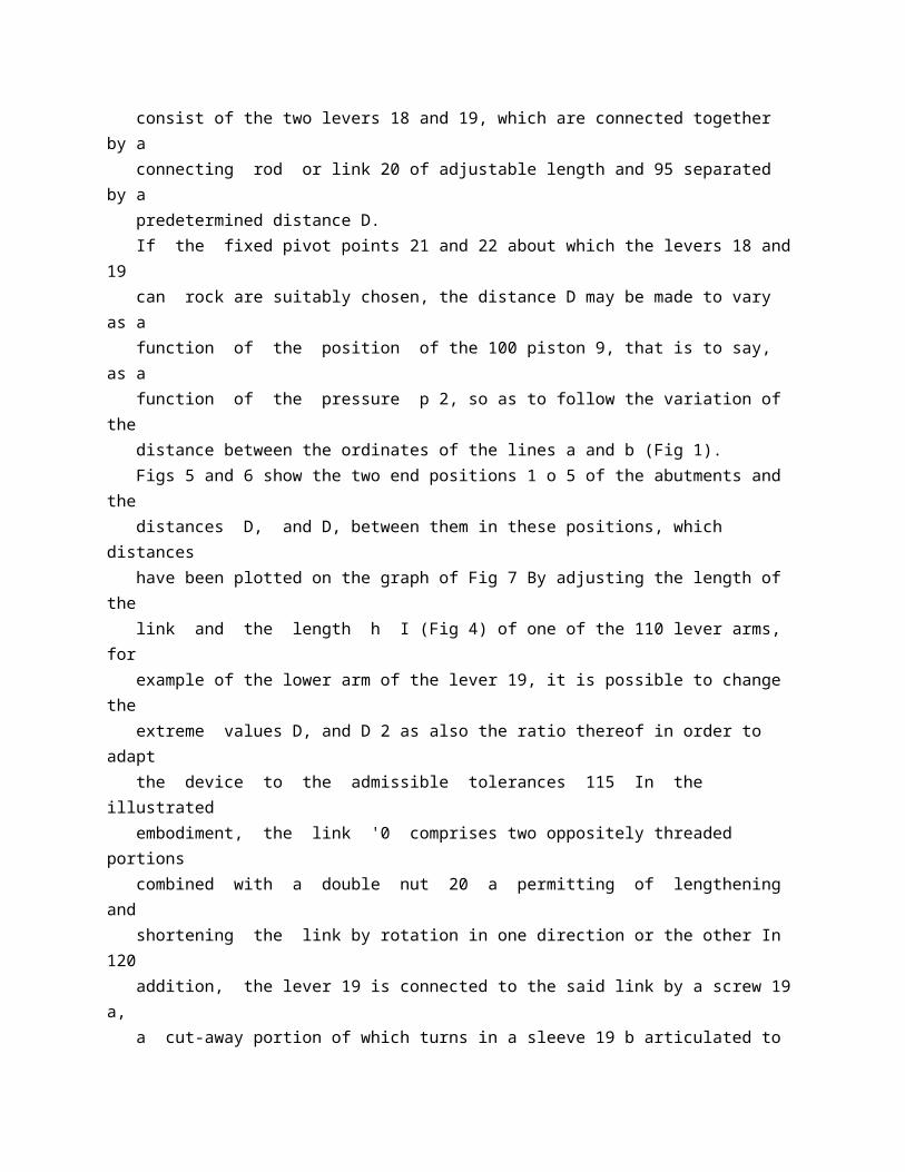
duct 15 The piston 9 is therefore moved to the right until the pistons 12 and 13 of the distributing slide valve again mask the orifices 7 and 8 In the contrary case (under the action of an increase of p), the oil enters So) the chamber 14 through the orifice 8 and port 16, and the oil situated in the chamber 11 flows to the outside through the orifice 7 and duct 15 In this case, the spring 17 maintains the slide valve 6 in contact With 85 the capsules 4 and causes it to follow its movement towards the left The movements of the piston 9 therefore always correspond to the movements of the capsules. The two abutments for the limitation of 90 the travel (of the regulating device 2) are coupled to the piston 9 These two abutments consist of the two levers 18 and 19, which are connected together by a connecting rod or link 20 of adjustable length and 95 separated by a predetermined distance D. If the fixed pivot points 21 and 22 about which the levers 18 and 19 can rock are suitably chosen, the distance D may be made to vary as a function of the position of the 100 piston 9, that is to say, as a function of the pressure p 2, so as to follow the variation of the distance between the ordinates of the lines a and b (Fig 1). Figs 5 and 6 show the two end positions 1 o 5 of the abutments and the distances D, and D, between them in these positions, which distances have been plotted on the graph of Fig 7 By adjusting the length of the link and the length h I (Fig 4) of one of the 110 lever arms, for example of the lower arm of the lever 19, it is possible to change the extreme values D, and D 2 as also the ratio thereof in order to adapt the device to the admissible tolerances 115 In the illustrated embodiment, the link '0 comprises two oppositely threaded portions combined with a double nut 20 a permitting of lengthening and shortening the link by rotation in one direction or the other In 120 addition, the lever 19 is connected to the said link by a screw 19 a, a cut-away portion of which turns in a sleeve 19 b articulated to the link at 19 c. Fig 4 illustrates the invention as adapted 125 to a regulation in which the centrifugal force of flywheel weights 26 driven by the shaft of the turbo-engine is used for adjusting the speed of rotation. For changing the speed of rotation of the 130 784,690 engine and obtaining, for example, a higher speed of rotation, the control lever 23 is rocked to the right so that the cam 24 increases the force of the adjusting spring 25, which has hitherto been in equilibrium with the thrust of the weights 26 Consequently, the slide valve 27 is moved and opens the passage 28 The oil under pressure arriving through the passage 30 flows through the passage 28, enters the compartment 31 and moves the servo-piston 1 The oil which was situated in the compartment 32 is expelled through the passages 29 and 34 The movement of the
servo-piston 1 produces through the movement-multiplying lever la a displacement of the regulating piston 2 in the direction corresponding to an increase in the flow of fuel to the burners 35 and this movement continues until the end 2 e of the rod of the regulating piston comes, into contact with the abutment 18 At this instant, the point "E" of the graph of Fig 8 is reached From this point, the increase in the speed of rotation is controlled by the increase in the pressure p, along the curve a corresponding to the mismatching limit, since the regulating member follows the movement of the capsules 4 and of the piston 9 controlled by the pressure p 2, as hereinbefore described. When the point "F" of the graph of Fig. 8 is reached, the thrust of the weights 26 and that of the spring 25 are again in equilibrium, that is to say, the passages 28 and 29 are again closed by the bosses of the slide valve 27 The impulse to which the regulating member has been subjected then ceases The regulating member finally takes up an intermediate position in which the quantity of fuel corresponds to the point "G" on the characteristic curve c The desired speed of rotation is thus reached. The graph of Fig 8 shows the movements of the regulating member in the case of acceleration, while the graph of Fig 9 illustrates the case of deceleration. It will be appreciated that it is possible through the intermediary of the piston 9 to ensure a perfectly stable supporting of the end 2 e of the rod of the regulating member by the levers 18 and 19 regardless of the forces exerted on this regulating member by the piston 1. It will also be appreciated that the invention affords the advantage of reducing the acceleration and deceleration times for changing from one state of operation to another, while ensuring reliable operation of the jet unit.
* Sitemap * Accessibility * Legal notice * Terms of use * Last updated: 08.04.2015 * Worldwide Database * 5.8.23.4; 93p
* GB784691 (A)
Description: GB784691 (A) ? 1957-10-16
Improvements relating to trucks
Description of GB784691 (A)
PATENT SPECIFICATION Inventor: HERBERT JOHN FRAMHEIN 7 $z Date of application and filing Complete Specification: June 17, 1955. \) No 17544155. Complete Specification Published: Oct 16, 1957. Index at acceptance:-Classes 79 ( 3), A 2 (D: P); 79 ( 4), B 3 82; and 79 ( 5), H( 5: 12: 24). International Classification:-B 62 d, f. COMPLETE SPECIFICATION Improvements relating to Trucks We, THE YALE AND TOWNE MANUFACTURING COMPANY, a Corporation organised under the laws of the State of Connecticut, United States of America, of 405, Lexington Avenue, New York 17, State of New York, United States of America, do hereby declare the invention, for which we pray that a patent may be granted to us, and the method by which it is to be performed, to be particularly described in and by the following statement: - This invention relates to a truck of the type illustrated in British Specification 630,290, employing a combined steering and traction wheel for very sharp steering of the truck in order to permit the use thereof in narrow aisles such as are found in industrial plants and warehouses In the truck of our patent a very short turning radius is possible through the mere turning of the combination traction and steering wheel However, it has been found that trucks of the particular class lack the stability of a four wheel truck in which the load platform is naturally supported at four points, or even of a three wheel truck where two of the wheels are arranged along one longitudinal axis and the third wheel on a laterally spaced axis. The problem is further complicated, naturally, when the truck is of the pallet lifting type in which a very low platform is adapted to enter between the upper and lower floors of a conventional industrial pallet. Naturally, pallet trucks must have a lifting wheel under each side of one end of the lifting platform, these wheels being adapted to enter the pallet. In order to solve lhe problem, it has been proposed that a truck of the particular class have four wheels, two being the load supporting
wheels under the lifting platform, while the other two wheels are carried by the forward end of the truck or that end of the truck on which the operator may wish to stand More particuarly, it has been proposed that one of the wheels at the forward lPrice 3 s 6 d) end of the truck be a caster wheel carried by the frame of the truck, and that the other wheel be a combined steering and traction wheel so It has been maintained that a truck so constructed will have the stability of a four wheel truck, while yet being just as manoeuvrable as the three wheel truck illustrated in our earlier patent However, it has 55 been found in a truck of the particular type that it is necessary to compensate for irregularities in the floor by providing a spring between the caster wheel and the frame of the truck to permit some vertical movement of 60 the caster wheel relatively to the truck On poor flooring it will be appreciated that the traction of the combined steering and traction wheel will vary constantly as the caster wheel moves to take up irregularities Of 65 course, under certain conditions the caster wheel will be unable to take up these irregularities and the frame will naturally distort, while frequently the weight on the traction wheel will be reduced to a point where trac 70 tion and braking are not very effective. Further, any wear on the traction wheel, and this will be rather considerable where the traction wheel carries a rubber tire, must be compensated for by vertical adjustment 75 Otherwise, there will be further distortion of the frame of the truck, while the spring action of the caster will become increasingly more effective as the wearing on the traction wheel tire increases So In addition, in a truck of the particular class having a traction and caster wheel combination, should the combined traction steering wheel be turned to a sharp angle with the caster wheel not aligned in the 85 direction of movement of the truck at that angle, there will be a tendency to shear the tire off the caster wheel Actually, if the caster wheel is at right angles to the direction of movement of the truck as determined 90 by the combined steering and traction wheel, it is possible to damage the caster wheel and Lh C 91 its tire. The particular problem thus presented to the prior art is rather considerable, and many solutions have been attempted over a period S of years We believe that the contribution set forth in this application is one that solves this long-standing problem Thus, according to the present invention, there is provided a truck of the type set forth comprising a truck frame, a pair of wheels for supporting one end of said truck frame, a beam, means pivoting said beam to the other end of said truck frame centrally of said beam and in the longitudinal axis of the truck to support the other end of said truck frame, means mounting a steering and traction unit as a unit on
one end of said beam adjacent one side of the truck frame for rotation bodily relatively to said beam, said steering and traction unit moving bodily as a unit with said beam as said beam pivots relatively to said truck frame, steering means for rotating said steering and traction unit bodily relatively to said beam, an idler wheel mounted on the other end of said beam adjacent to the other side of said truck frame for pivotal movement in an axis parallel to the axis of rotation of said traction unit relatively to said beam in response to steering movement of said steering and traction unit, said steering and traction unit comprising the combined steering and traction wheel and motor means for driving said combined steering and traction wheel only whereby the idler wheel does not contribute to the driving or braking of the truck, and a steering connection between the idler wheel and the combined steering and traction wheel. In addition, our truck is well supported on all types of flooring without distortion of the frame, while the tractive effort remains the same at all times due to the equalising action of the beam carrying the two wheels. Further, it is not necessary to adjust the traction unit and its steering and traction wheel to compensate for tire wear, because of the inherent construction of the truck. Objects and advantages of the invention will be apparent from the following description of a preferred embodiment of the invention, reference being had to the accompanying drawings in which:Fig 1 is a side view of a pallet truck that embodies our invention in a preferred form. Fig 2 is an end view of the truck shown in Fig 1 Fig 3 is a transverse sectional view showing the relationship of the beam to the frame of the truck Fig 4 is a vertical section taken on the line 4-4 of Fig 5 Fig. 5 is a plan view taken approximately on the line 5-5 of Fig 3, and indicating also the relationship of the wheels as they are turned for steering the truck Fig 6 is an end view similar to a part of Fig 2, but indicating the rocking action of the beam in passing ovei irregular ground. In the pallet truck that we have chosen to illustrate for the purpose of describing our invention, a load platform 10 is supported at its forward end upon the main frame 11 of 70 the truck and at its rear end upon wheels 12, this being a customary arrangement in the particular type of truck Also, as a source of power for the truck, a battery 13 is supported on the main frame 11 ahead of the 75 platform 10, and the steering and driving means for the truck are mounted on the frame forwardly of the battery 13 In the prior art, the front supporting wheels and the driving and steering means have taken 80 various forms,
but none of these have offered in the combination the advantages that are inherent in our novel construction now to be described. In our invention, we utilise a transverse IS beam 14 through which a traction wheel 15 and an idler wheel 16 adjacent opposed sides of the truck support the front end of the truck, and through which these wheels have a compensating movement that affords a very 90 efficient action of the steering and driving means This beam 14 is mounted to rock about the longitudinal axis of the truck, and for this purpose we provide a pivot pin 17 that is best seen in Figs 3 and 4 The pivot 95 pin 17 is mounted upon the frame 11 of the truck, and the ends of the pin 17 are rotatably held in a pair of vertical brackets 18 mounted between a pair of frame members 19 that form a part of the main frame of the 100 truck The pivot pin 17 is secured in a lug 14 a located centrally on the underside of the beam 14, this lug extending between the frame brackets 18 so as to prevent substantial end play of the beam relatively to the 105 truck The truck frame includes a transverse vertical member 20 and a U-shaped end member 21 between which the wheels 15, 16 are located, and to which the frame members 19 are assembled in a longitudinal 110 position between the wheels 15 and 16. The traction wheel 15 is a part of a steering and traction unit that rocks integrally with the transverse beam 14, and that also rotates on a vertical axis relatively to the 115 beam for steering the truck The steering and traction unit is mounted through a turn table 22 that rotates on ball bearings 23 in an opening in one end portion of the beam 14 The traction wheel 15 is mounted be 120 neath the turn table 22 by a pair of brackets 24, 25 in which rotate the ends of the drive shaft 26 upon which the traction wheel 15 is fixed The arrangement is such that the wheel 15 is centered relatively to the turn 125 table 22, so that when the turn table rotates the wheel pivots about its own central vertical axis The bracket 24, best seen in Fig. 3, is formed to provide a gear casing that encloses a gear 27 fixed upon the shaft 26 and 130 784,691 I such as the universal joints 47, 48 will absorb the rocking movement in the steering, while the ball joints on link 56 will act similarly for the breaking means. It will be appreciated that the wheel 16, 70 being an idler wheel, does not contribute to the driving and braking of the truck, and therefore the pivot pin 17 is normally required to accept the rather considerable eccentric forces that result from the position 75 of the traction wheel 15 entirely at one side of this pivot pin The pin 17 is quite capable of accepting these eccentric forces, but we nevertheless prefer to apply the propelling force of the traction unit to the frame of 80 the truck in a more direct manner, and for this purpose we utilise a torque finger 59 integrally mounted on the left hand portion of the transverse beam 14, as viewed in Fig 5.
As the beam 14 rocks, the torque finger 59 85 moves in the space between a pair of vertical wear strips 60 mounted on the frame 11. The torque finger 59 does of course bear against one or the other of the strips 60 depending upon the direction in which the force 90 is applied, and actually the driving force of the traction unit is accepted in a balanced fashion between the wear strips 60 and the pivot pin brackets 18. The idler wheel 16 is positively steered 95 The idler wheel 16 is mounted upon the beam 14 by a turn table 61 that in its essential respects is a duplicate of the traction unit turn table 22 Of course, because the idler wheel 16 is not driven, we utilise a simple U-shaped 100 bracket 62 for mounting the shaft 63 of the idler wheel relatively to the turn table 61. The particular arrangement places the turn table 61 below the driver's platform 36 with the idler wheel abreast of the traction wheel 105 15, the idler wheel 16 being mounted to rotate on its own central vertical axis, this axis being parallel to the steering axis of the traction wheel 15 Therefore, the normal motion of the truck produces no steering 110 effect upon the idler wheel 16, and in order to steer this wheel simultaneously with the traction wheel 15 we utilise the steering connection shown in Figs 4 and 5 This connection is in the form of a connecting rod 64 115 that is attached by pivots 65, 66 at its opposed ends to the traction wheel turn table 22 and to the idler wheel turn table 61 The pivots 65, 66 are angularly displaced a predetermined amount relatively to each other 120 when both of the wheels 15 and 16 are in straight ahead position, as will be understood by those acquainted with the art, so that the wheels in steering the truck will both tend to swing the truck about a common 125 center.
* Sitemap * Accessibility * Legal notice * Terms of use * Last updated: 08.04.2015 * Worldwide Database * 5.8.23.4; 93p
* GB784692 (A)
Description: GB784692 (A) ? 1957-10-16
Improvements in or relating to processes and machines for the continuousproduction of sections from synthetic resins
Description of GB784692 (A)
A high quality text as facsimile in your desired language may be available amongst the following family members:
US2822575 (A) US2822575 (A) less Translate this text into Tooltip
[79][(1)__Select language] Translate this text into
The EPO does not accept any responsibility for the accuracy of data and information originating from other authorities than the EPO; in particular, the EPO does not guarantee that they are complete, up-to-date or fit for specific purposes.
COMPLETE SPECIFICATION Improvements in or relating to Processes and Machines for the Continuous Production of Sections from Synthetic Resins We, RENE IMBERT and PIERRE DE VIN- ZELLES, both citizens of the French Republic, the former of 14 Rue Ibn Batouta, Casablanca, Morocco, and the latter of 10, Rue C sar Frank, Casablanca, Morocco, do hereby declare the invention, for which we pray that a patent may be granted to us, and the method by which it is to be performed, to be particularly described in and by the following statement : Synthetic materials obtained by polymerization or polycondensation processes and available in fluid condition but capable of being hardened through a heat and/or chem ical treatment are more and more employed for producing a wide variety of articles. It is a conventional practice to associate such materials with reinforcements, particularly to impregnate fibrous reinforcements with such materials and, in some cases, to superimpose a plurality of fiber webs thus impregnated with a view to obtaining a final laminated product made up 6f fibrous strata impregnated with resin: the fibrous reinforcements may be made of glass fibers, for example felted into a mat, or weaved, braided, knitted or likewise made into fabrics wherein the component fibers extend in particular directions instead of at random. As starting materials for the manufacture of laminates, unsaturated
polyesters produced from the reaction of polyacids with polyalcohols (at least one of the monomers being an unsaturated compound) and which are still in flowing condition, the big mole- cules thereof being substantially linear, are particularly desirable. For effecting a crosslinking between the big linear molecules and thereby hardening the polyester,' a crosslinking monomer which may additionally play the part of a solvent for the linear polyester may be employed. With a view to causing or promoting hardening, an accelerator or drying agent may be added. Unsaturated linear polyesters which are commonly employed are ethylene glycol polymaleates or polyfumerates, or allyl poly phthalates. For the purpose of accelerating the rate of setting, acyl peroxides (benzoyl, lauroyl, capryl and like peroxides), ketones such as methyl ethyl ketone, ketone peroxides, in particular cyclohexanone peroxide, cyclohexyl hydroperoxide, tertiary butyl peroxide, diazo compounds and so on, are employed as catalysts by amounts of about 0.1 to about 5 per cent. As promoters, cobalt salts, particularly cobalt naphtenate of cobalt maleate, manganese salts, aromatic polyamines, dimethyl aniline and other compounds are usually employed, depending upon the catalyst which is selected. Whether polyester or epoxide (ethoxylin) resins are considered, seeping is effected in most cases with the help of heat or anyhow can be caused in that way. For that reason and for the sake of convenience, polyester resins and epoxide resins will be considered herein as members of the general class of thermo-setting resins. This invention generally relates to the manufacture of hard sections, reinforced or not, from fluid or pasty resins which are capable of being given a predetermined shape and whose hardening can be effected by applying heat thereto: such resins will hereinafter be referred to as thermosetting materials. The invention relates more particularly to the continuous production of hard sections, whether reinforced or not, having an indefinite length and constant cross-sections, for example plates, sheets. bands, tubing and the like. It is generally known to develop heating materials by placing the same in an alternating field of high-frequency. More particularly it has previously been proposed to move a material progressively through a high frequency field and through a press, for example a press comprising a series of pairs of press ing rollers. Heating by means of high frequency currents has also been proposed for melting- a heat-hardenable adhesive agent, after which the molten agent is hardened while it is interposed between the surfaces to be united. It has further been proposed to subject a thermosetting material containing a sponging agent to the effects of a high-frequency electrostatic field, in a process for converting a body of such
material to the cellular condition. The present invention comprises a process for curing a thermosetting material, more particularly a polyester or epoxide resin, in which high frequency electric waves are passed through the material. According to the invention a series of trains of high frequency electric waves spaced apart by time intervals longer than the duration of one train are passed through the thermosetting material between two conductors in direct contact therewith or separated therefrom by a film of a mold release agent. As an electric wave train is released, it causes through dielectric losses, an internal heating which is distributed homogeneously through the whole mass traversed by the waves, and either as a consequence of or parallel with said heating, an exothermic reaction is triggered more particularly in the case of unsaturated polyesters; the e,\otherm- ic reaction may proceed after the wave train has ceased to pass and presumably corresponds to a starting or a continuance of crosslinking reactions. With alternating periods of passage of high frequency current and periods of rest, it is thus possible to increase the temperature in the thermosetting material by successive heat supplies which are delivered partly from outside with a consumption of electrical energy and partly, in the periods of rest, by chemical internal reactions which have been started electrically. It is then found that the period for obtaining a hard product is greatly reduced and may be of the order of one second or a few seconds. The most effective frequencies (which vary in accordance with the materials to be treated) are of the order of one megahertz to several hundreds of megahertz, particularly of the range of about 30 to about 50 megahertz. Instead of continuously passing the material through a curing zone or spacedapart curing zones as will hereinafter be des- cribed, setting may be promoted by passing wave trains through the material. In that case. the period of passage of a wave train may be of the order of a quarter of a second. It is generally desirable to pass at least two and up to ten or more wave trains, separated by rest intervals of the order of two to fifteen seconds. According to the preferred embodiment of this invention, the thermosetting material is passed at a predetermined rate through high frequency electrical wave generating zones, which are stationary and mutually spaced apart, so that each cross-section of the material is acted upon by wave trains in the conditions above defined, and the material is shaped or formed to the desired cross-section in at least one of said zones while said material is being subjected to the action
of electrical waves; the material may be treated in the form of an uninterrupted length of any extent, or in the form of successive sections. For carrying the preferred embodiment into effect, this invention comprises a shaping and curing machine in which the essential parts comprise a group of complementary shaping members made of a conducting material, inserted in a high frequency electrical circuit and defining between them a channel of predetermined cross-section for shaping the material which passes therethrough to the desired cross-section. All shaping members or some of them may be stationary: as an example of a stationary shaping member there may be mentioned a table on which the material is passed in its travel and which provides a support therefor. The complementary shaping members are employed as armatures for condensers in which the dielectric is constituted by the material passed through the channel defined by said shaping members. In practice, the machine comprises several successive groups of compleinen- tary shaping members. Each group thus plays a double part, viz, maintaining an alter nating potential difference between opposite surfaces of the thermosetting material, and mechanically shaping the material to the desired cross-section. For preventing the thermosetting material from sticking to the shaping members, a film of a mold release agent may be maintained or kept up on the operative surface of the shaping members, or a strip or sheet of mold release agent may be passed between said operative surface and the surface of the thenno- setting material. Where laminated sections having constant cross-sections are to be produced continuously a machine according to this invention may comprise before the first group of shaping members, one or more spools each arranged for the delivery of a sheet or band of reinforcing fibrous material, and means located before the ingress of said sheet or band into the channel defined between the shaping members of the first group, for depositing thermosetting material, a catalyst if need be, and as the case may be an accelerator or promoter on said sheet or band, unless such ancillary material or materials have already been incorporated in said thermosetting material. The ancillary material or materials referred to may be deposited by spraying, dipping, spreading (e.g., with a knife) brushing or the like. Other features and objects of this invention will become apparent from the following description of preferred embodiments thereof, when taken in conjunction with the accompanying drawings given by way of nonlimiting examples. Fig. 1 is a diagrammatic sectional elevation of a shaping and curing machine in accordance with this invention, for the product tion of sections having an indefinite length and constant, non-tubular
sections; Figs. 2 to 4 are elevation views of groups of shaping rollers; Fig. 5, similar to Fig. 1 shows a like machine adapted for the production of an indefinnite length of tubing; Fig. 6 is a cross-section taken along line VI VI on Fig. 5; Fig. 7 is an electrical diagram of a high frequency device for applying a high alternating potential to a pair of shaping rollers; Figs. 8A and 8B show modifications of the diagram of Fig. 7 in the case of the production of tubing; Fig. 9 is another electrical diagram in which each pair of shaping rollers is associated with an oscillator. Referring to the diagrammatic showing of Fig. 1, a shaping and curing machine for the production of sections having an indefinite length and constant, non-tubular cross-section comprises three successive sets for shaping and applying high frequency electrical current which in this instance is supposed to be delivered from a common generator 1; each set comprises a group of two shaping rollers 2a-2b, 3a-3b, 4a-4b having complementary profiles, made of conducting material and connected in parallel to the terminals of generator 1. As shown, a table 5 for guiding and supporting the material in the process of treatment may be provided between the successive roller groups, and may extend as shown beyond the final shaping group 4a4b Arranged before the shaping roller groups and rotatably supported for delivering individual webs of reinforcing fibrous material, for example glass fiber mats or glass fiber cloths, are spools 6, 7, 8; further spools 9, 10 are likewise arranged and supported to deliver individual films of mold release agent, for example regenerated cellulose films, for preventing the thermosetting material from sticking to the shaping rollers; arranged to spray thermosetting materials on each face of the fibrous material webs are nozzles 11, 12, 13 and 14; the thermosetting material may already contain a catalyst and, as the case may be, an accelerator or promoter; alternatively, further nozzles (not shown) may be provided to spray such ancillary agent or agents in the rear of the thermosetting material spraying zones. Finally squeezing devices (not shown) or equivalent devices for removing excess thermosetting and ancillary materials from the fiber webs preferably are provided in the rear of the nozzles. The shaping rollers such as 2a and 2b may be cylinders having smooth peripheral surface, or peripheral surface comprising portions in high or sunken. relief, for example mottled or corrugated. Fig. 2 shows an example of a pair of rollers one of which 15a is bulged intermediate the ends thereof while the other one 16b has a corresponding groove,
for producing a trough-shaped laminate 16. It is possible to effect a stepwise shaping where the section to be produced should have a more complicated profile. Figs. 3 and 4 illustrate how such a stepwise shaping can be effected in the case where- a U-shaped section is to be obtained. In that case, the first shaping group or each one of the first shaping groups comprises two rollers 17a, 17b (Fig. 3) of less width than the web or webs impregnated with thermosetting material in order that only the middle portion 18 of the same is cured or partly cured by the action of said rollers while the marginal portions 19 are not or substantially not cured; in addition to the rollers referred to, side tables (not shown) may be provided to support said marginal portions 19. Following the shaping group or groups 17 are one or more groups of shaping rollers 20tz-20b, 21a-2lh (Fig. 4) having vertical axes, for causing curing or incipient curing of the marginal portions 19, previously bent up for example by skew guiding surfaces. Arranged to support the bottom face of the U-section 18 while the marginal portions are bent up and then cured, is a table 22. Where shaping is thus effected by successive steps, it is generally desirable not to employ an accelerator or to apply such an accelerator only locally, at first on the middle portion 18 before it enters the nip between rollers 17a-17b, then past said rollers on the marginal portions 19 before said marginal portions reach rollers 20-21. In the machine so far described, one or more groups of shaping rollers may be driven to cause progression of the material which is being cured; alternatively or additionally, roller groups adapted to draw the material may be provided after the last shaping roller group 4a-4b. It should be understood that the foregoing example is not limiting and purports to villus trate various possibilities at the disposal of one skilled in the art. As stated above, feed spools such as 9 and 10 may be omitted and in that case provision should be made to maintain or renew a film of mold release agent on the rollers, tables and like parts of the machine. Instead of being sprayed with the thermo setting material and, as the case may be, ancillary materials which have not as yet been assocated therewith, the fibrous webs supplied from spools such as 6, 7, 8 may be impregnated with thermosetting material by being passed through a vat containing the same, then if required squeezed or similarly handled and thereafter, as the case may be, sprayed with an accelerator before engaging the first group of shaping members. It should be understood that this invention is not restricted to any specific manner of impregnating fibrous webs with thermosetting materials.
Figs. 5 and 6 illustrate the arrangement of the essential parts (with a diagrammatic showing) of a shaping and curing machine designed for the production of tubing. The essential parts comprise a central mandrel 23 made of conducting material, connected to a terminal of a high frequency wave generator 24, and successive groups of shaping members such as groups of grooved rollers 25a-25b, 26a-26h, 27a-27b and 28a- 28b, each arranged around mandrel 23; for the sake of simplicity in the showing, it has been asumed that the various groups are connected in parallel to the other terminal of generator 24. The machine further comprises means to provide an anti-adhesive sheath around the mandrel and means for covering said sheath with one or more fibrous webs impregnated with thermosettina material. According to the example shown, the first means comprise spools 29, 30 for delivering regenerated cellulose films 31, 32 and a conical guide 33 for incurving the films and causing the same to fit around the mandrel into a split sheath. The second means, of a well-known type, comprise one or several braked spools 34 adapted to deliver a web 35 of fibrous material and rotatably supported in oblique position on a turntable 36 borne on rollers. The mandrel 23 thus receives a simple or multiple helical winding of fibrous material. The numerals 38 and 39 denote nozzles for spraying thermosetting material on both faces of web 35: as described with reference to Fig. 1. additional nozzles may be provided to spray ancillary materials on the web at places where the web has already received thermosetting material. instead of winding fibrous web 35 directly around the regenerated cellulose films, it is possible to cover said films with intermediate fibrous webs impregnated with thermosetting material and arranged lengthwise like said films, then to wind web 35 spirally around said intermediate webs so that the drawing force in stripping the films is not applied directly to web 35 and thus is not likely to distort said web, Alternatively or additionally, the means for laying up fibrous webs may comprise a conical guide similar to guide 33 for causing a sheath of webs unwound from spools arranged like spools 29, 30, to be fitted around the regenerated cellulose sheath. In that case it is preferred to impregnate the inner face of each web before the web enters the conical guide. and to impregnate the outer face after the web egresses out of said guide. The conical guide 33 may also be arranged both for fitting the regenerated cellulose sheath around the mandril and for fitting fibrous webs around said sheath. Whetller the first conical guide for fitting fibrous webs around the regenerated cellulose sheath is the conical guide 33 or is separate therefrom and located
thereafter. said first guide may be followed with one or several similar guides adapted and arranged for laying up successive layers of fibrous material. The above described manner of causing the material to progress through the machine shown on Fig. 1, is also applicable to the machine for the production of tubing according to Fig. 5. Whatever the case may be, where a rotary shaping member is not cylindrical, it may comprise a pile of disks which are coaxial but mutually independent so that they can rotate at the same peripheral speeds in spite having different diameters. With a view to applying a high alternating potential difference. preferably at a high frequency, any suitable source of alternating voltage may be employed. In that respect. it is preferred to insert in an oscillating circuit tuned to resonance, the condenser which is provided by the shaping members together with the thermosetting material plaving the part of a dielectric. For that purpose. the oscillating circuit comprising such a condenser i5 preferably directly coupled with an oscillating tube to control the oscillating frquencv of said tube. in order that any freguenev shifting caused by varirrtions of the condenser capacity do not result in untuning the oscillatine circuit. It should be understood in that reeard that slight variations in the thickness of the material UX.h7c17 is being treated or in tulle dielectliC properties thereof are capable of altering the condenser capacity. For example the mounting diagram shown on Fig. 7 mQv be employed. The condenser comprising a pair of shaping rollers 40a-40h and the material 41 to be shand is connected to the ends of a winding 4 to provide an oscillating circuit. Magnetically coupled with winding 42 is another winding 43 inserted in the anodic circuit of a triode 44. and the oscillations are maintained by means of the grid circuit winding 45 which is also coupled magnetically with the first two windings. With a view to causing the mounting to oscillate, the magnetic coupling of windings 47, 43 and 45 is variable; the frequency is determined by the oscillating circuit L C constituted by the induction coil 42 and the condenser 40a, 40b, 41. For the purpose of bringing the alternating potential thus set up between members 40a, 40b to a level just below that corresponding to disruption of the dielectric 41, one of the windings, for example winding 43, may have a variable connection in order that the number of turns of the winding coupled with the oscillating circuit may be varied. Where the shaping members are designed for the production of tubing,
i.e., where they co-operate with an internal mandrel, any one of the mounting diagrams shown on Fig. 8B may be employed. Referring to Fig. 8A, shaping members 46a, 46b are connected to the ends of winding 42 while mandrel 47 is earthed or vice versa. In the case of Fig. 8B, one of the ends of winding 42 is connected to mandrel 47 while the other end of said winding is connected in parallel to the shaping members 46a, 46b. Where several pairs of shaping members are provided to act successively on the thermosetting material, the various shaping members may be energized from the same alternating potential generator. Preferably each pair of shaping members is inserted in an oscillating circuit energized from an independent oscillating tube. The mounting may be as shown on leig. 9. Each pair of shaping members 48a-48b, 49a-49b, 50a-50b is associated with an induction coil, specifically coils 51, 52, 53, coupled with anodic coils 54 55, 56 of triodes 57, 58, 59. In each one of the oscillators thus constituted a condenser 60, 61 or 62 provides for the required coupling between the grid and the anode, to maintain oscillations. Electrical energy is supplied to the oscillating mountings from a common source, which may be a low voltage line 63 and a high voltage line 64. With a view to avoiding parasitic couplings between the various oscillators condensers 65, 66 and 67, which may be associated with induction coils 68, 69 are provided so as to prevent high frequencies set up by an oscillator, from interfering with frequencies set up by an adjacent oscillator. A machine similar to that shown on Fig. S may also be employed for the purpose of covering wires or cables, i.e., where a metal core which will remain within the final product is substituted for mandrel 23. In that case, the conical guide 33 may be arranged to act as a squeezing device for threads or the like impregnated with thermosetting material, which are delivered in a similar manner to films 31, 32 to provide a covering bundle around the core; around the bundle is then laid or wrapped a strip of regenerated cellulose film which for example is wound in the same manner as web 35, or the bundle may be covered with a mold release agent in any other manner. In that case, instead d placing the shaping rollers 25, 26, 27, etc., as shown on Eig. i e shifting each pair of rollers by 909 with respect to the next preceding one, it is desirable to have a smaller shifting angle, for example to place the second pair at 60 from the first one, and the third pair at 1203. Again, instead of connecting the pairs of rollers to a terminal of the source of current and the cable core to the other terminal, every second pair of rollers may be connected to one terminal and the other pairs to the other terminal.
It should be understood that this invention is not limited to the examples given above. In particular the reinforcing or filling material associated with the thermosetting material may be in any other form than that of fibers woven or felted into a web, or no reinforcing or filling material at all may be employed. In that case, the machine may sim- ply have, before the first group of shaping members, a device for the delivery d thermosetting material (as such or previously admixed with filling or reinforcing material), for example a die, an extruding head, a pair of rollers or the like which delivers a band, a strip, a sheet, a tube or like length of said thermosetting material or a mix containing the same. What we claim is : 1. A process for curing a thermosetting material, more particularly a polyester or epoxide resin, wherein a series of trains of high frequency electric waves spaced apart by time intervals longer than the duration of one train are passed through the thermoset- ting material between two conductors in direct contact with said material or separated therefrom by a film of mold release agent. 2. A process as claimed in Claim 1, where in the electrical waves have a frequency of the range of one megahertz to several hundreds of megahertz, particularly of from about 30 to about 50 megahertz. 3. A process as claimed in Claim 1 or in Claim 2. wherein two to ten or more wave trains. each of which has a duration of about one quarter of a second, are passed through the thermosetting material at time intervals of the order of at least two seconds. 4. A process as claimed in any one of the foregoing claims for the continuous production of sections havin an indefinite length and constant cross-section, wherein the thermosetting material is passed uninterruptedly at a predetermined rate through high frequency electric wave generator zones which are stationary and spaced apart from one another, and the thermosetting material is shaped to the desired profile in at least one of said


![[4281] – 602 - Savitribai Phule Pune University · 2013-02-13 · [4281] – 602-2-5. a) Define Gueridon service. Any two disadvantage and advantages of gueridon service. 4 ...](https://static.fdocuments.us/doc/165x107/5b1ded4f7f8b9a45138b572b/4281-602-savitribai-phule-pune-2013-02-13-4281-602-2-5-a.jpg)