
4281 -06 Sandwich Structures
26
Aerospace Structural Design MAE 4281 Sandwich Structures David Fleming Associate Professor Aerospace Engineering
-
Upload
andrew-gilbride -
Category
Documents
-
view
79 -
download
3
description
Powerpoint on sandwich structures in aerodynamics applications
Transcript of 4281 -06 Sandwich Structures
Aerospace Structural Design
MAE 4281
Sandwich Structures
David FlemingAssociate Professor
Aerospace Engineering
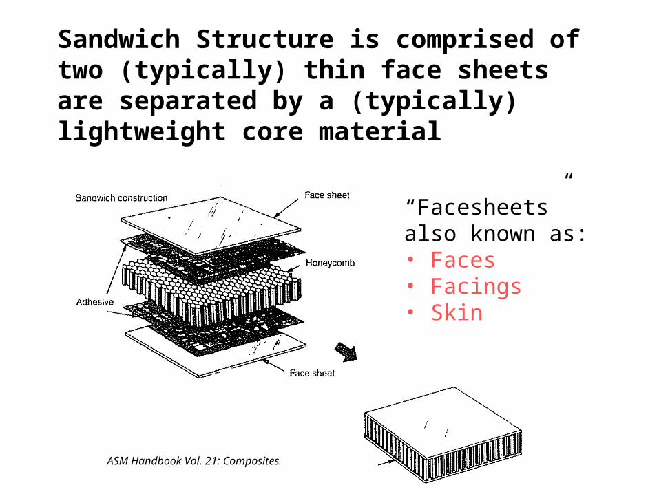
Sandwich Structure is comprised of two (typically) thin face sheets are separated by a (typically) lightweight core material
“Facesheets” also known as:• Faces• Facings• Skin
ASM Handbook Vol. 21: Composites

Sandwich Structures are particularly efficient in bending applications
Sandwich structures may be used for a variety of purposes, including to provide insulation, or fire resistance capabilities, for example, but the most common reason for utilizing sandwich structures is: Sandwich structures can provide exceptional strength-to-weight and, especially, stiffness-to-weight characteristics for structures
loading in bending.
ASM Handbook Vol. 21: Composites
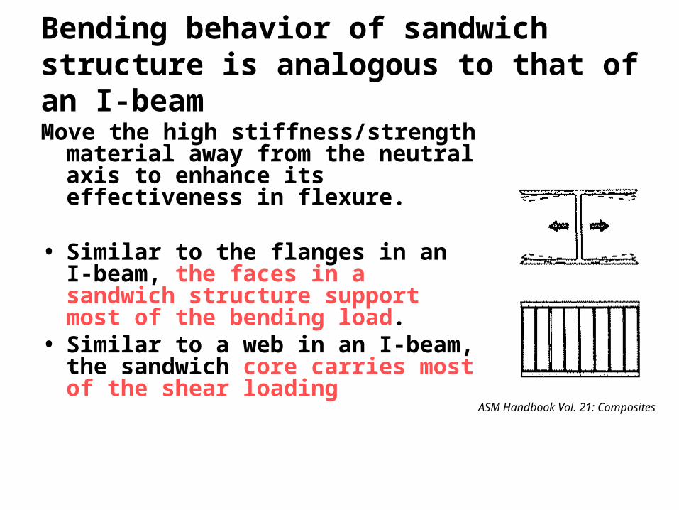
Bending behavior of sandwich structure is analogous to that of an I-beam
Move the high stiffness/strength material away from the neutral axis to enhance its effectiveness in flexure.
• Similar to the flanges in an I-beam, the faces in a sandwich structure support most of the bending load.
• Similar to a web in an I-beam, the sandwich core carries most of the shear loading
ASM Handbook Vol. 21: Composites

Applications of sandwich structures are numerous throughout aerospace
Cirrus S20:“All primary structures (wing skins, spars, ribs, fuselage skins, firewall, bulkheads, floors, ribs and longerons, cowling, fairings, horizontal skins, ribs and spars) are manufactured from Divinycell® HT 70 sandwich composite.”
www.diabgroup.com/europe/literature/e_pdf_files/e_pia_pdf/aero/cirrus.pdf
Bell M427“About 80 percent of the Bell M427 airframe is made from composite materials, the majority of which are carbon/epoxy.”
www.compositesworld.com/hpc/issues/2005/March/773
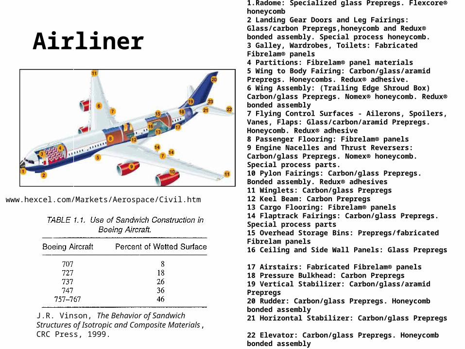
Airliner1.Radome: Specialized glass Prepregs. Flexcore® honeycomb 2 Landing Gear Doors and Leg Fairings: Glass/carbon Prepregs,honeycomb and Redux® bonded assembly. Special process honeycomb. 3 Galley, Wardrobes, Toilets: Fabricated Fibrelam® panels 4 Partitions: Fibrelam® panel materials 5 Wing to Body Fairing: Carbon/glass/aramid Prepregs. Honeycombs. Redux® adhesive. 6 Wing Assembly: (Trailing Edge Shroud Box) Carbon/glass Prepregs. Nomex® honeycomb. Redux® bonded assembly 7 Flying Control Surfaces - Ailerons, Spoilers, Vanes, Flaps: Glass/carbon/aramid Prepregs. Honeycomb. Redux® adhesive 8 Passenger Flooring: Fibrelam® panels 9 Engine Nacelles and Thrust Reversers: Carbon/glass Prepregs. Nomex® honeycomb. Special process parts. 10 Pylon Fairings: Carbon/glass Prepregs. Bonded assembly. Redux® adhesives 11 Winglets: Carbon/glass Prepregs 12 Keel Beam: Carbon Prepregs 13 Cargo Flooring: Fibrelam® panels 14 Flaptrack Fairings: Carbon/glass Prepregs. Special process parts 15 Overhead Storage Bins: Prepregs/fabricated Fibrelam panels 16 Ceiling and Side Wall Panels: Glass Prepregs 17 Airstairs: Fabricated Fibrelam® panels 18 Pressure Bulkhead: Carbon Prepregs 19 Vertical Stabilizer: Carbon/glass/aramid Prepregs 20 Rudder: Carbon/glass Prepregs. Honeycomb bonded assembly 21 Horizontal Stabilizer: Carbon/glass Prepregs 22 Elevator: Carbon/glass Prepregs. Honeycomb bonded assembly 23 Tail Cone: Carbon/glass Prepregs
www.hexcel.com/Markets/Aerospace/Civil.htm
J.R. Vinson, The Behavior of Sandwich Structures of Isotropic and Composite Materials, CRC Press, 1999.
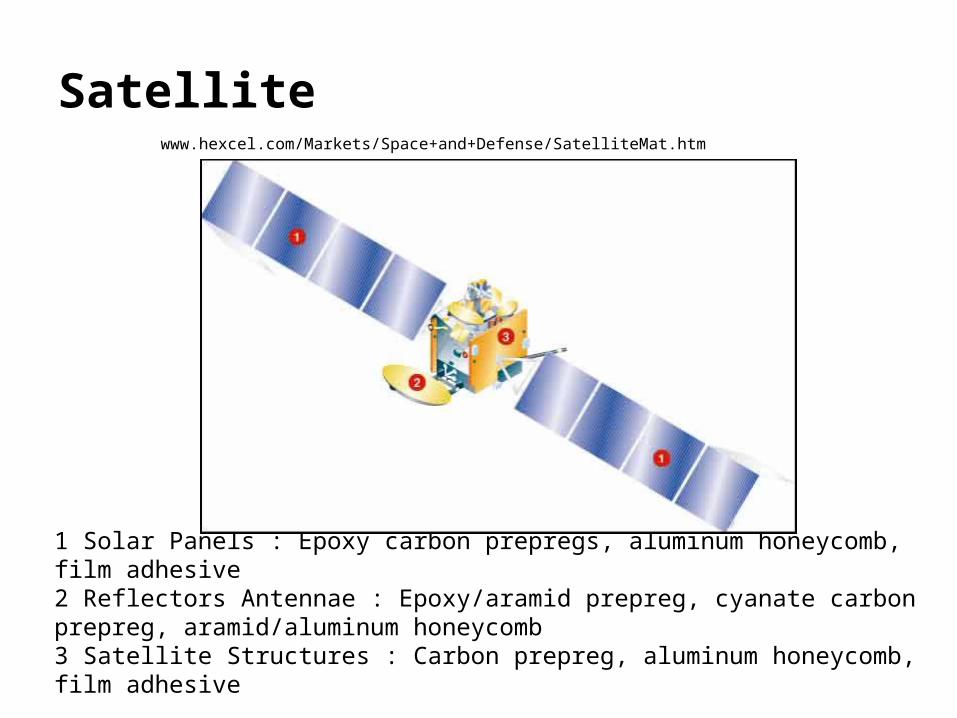
Satellite
1 Solar Panels : Epoxy carbon prepregs, aluminum honeycomb, film adhesive 2 Reflectors Antennae : Epoxy/aramid prepreg, cyanate carbon prepreg, aramid/aluminum honeycomb 3 Satellite Structures : Carbon prepreg, aluminum honeycomb, film adhesive
www.hexcel.com/Markets/Space+and+Defense/SatelliteMat.htm
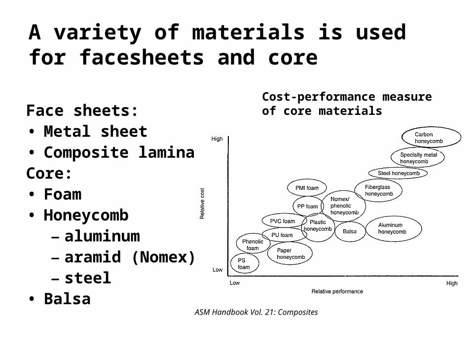
A variety of materials is used for facesheets and core
Face sheets:• Metal sheet• Composite laminateCore:• Foam• Honeycomb
– aluminum– aramid (Nomex)– steel
• BalsaASM Handbook Vol. 21: Composites
Cost-performance measure of core materials

Sandwich Panel covers large surface areas, Sandwich Beam is more 1-D
Hexcel Publication No. AGU 075b, 2000.
Sandwich Panel Sandwich Beam
ASM Handbook V. 21

Analysis of a sandwich beam is based on similar idealizations as a stiffened web structure
Assuming skin much stiffer than the core:Normal stresses much larger in faces than in coreAssuming core much thicker than the faces:Transverse shear stress much larger in core than in facesVariation in normal stresses across face are small
Hexcel Publication No. AGU 075b, 2000.
Consider bending:

Idealized AnalysisCan idealize the response based on
assumptions:• Core thick compared to faces• Faces stiff compared to core (in axial
direction of beam)Results in the following simplifications:• Assume uniform normal stress within
each face (if structure is asymmetric, the faces may carry different stresses). Analytically, it will be more convenient to work in terms of the total load carried by each face.
• Neglect transverse shear stresses in the faces
• Assume transverse shear stresses are constant in the core
• Neglect normal stresses in the core

Idealized Analysis
Simple statics:
22
11
21
21
21
21
2
2
2
bht
M
bt
P
bht
M
bt
P
tt
MP
ttt
ttth
h
Mtt
t
MP
tttPM
f
f
fcf
f
c
c
f
cf
2
1
:as expressed
be can faces the in stress Average
thickness face equal For
where
faces. theby carried
actually is that load
shear the for factor
correction a provide
to of place in
used is :Note
c
c
t
hbh
V
Axial Loading in Faces Shear in Core
Note: Notation 1 and 2 here do not refer to principle stress,
rather to the face number 1 and face number 2.

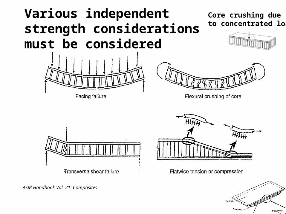
There are many modes of failure possible for sandwich structures
• Strength of constituents• Faces• Core
• Instability• General instability (buckling of complete
panel/beam)• Local instability
• Face Wrinkling• Intracell buckling (dimpling)
• Interface failure
ASM Handbook Vol. 21: Composites
Core crushing dueto concentrated load
Various independent strength considerations must be considered

Instability can appear in a variety of forms
ASM Handbook Vol. 21: Composites
Vinson

Failure Analysis must consider all relevant failure modes
Design of a sandwich panel must select face/core material and dimension such that positive margins of safety are obtained for all of the possible failure modes.
We will look at some of these in detail, others qualitatively.
For more information: “Analysis of Sandwich Structures,” in ASM Handbook,
Vol. 21 (in Library reference section)“HexWeb Honeycomb Sandwich Design Technology,”
Hexcel Pub. No. AGU 075b (Available on-line)
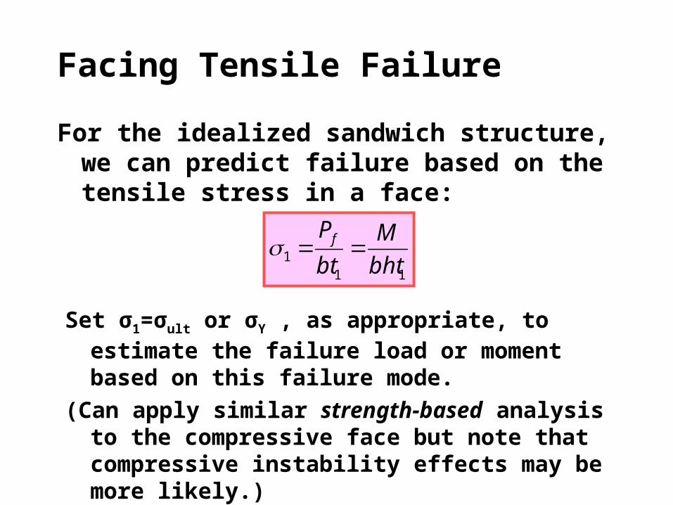
Facing Tensile Failure
For the idealized sandwich structure, we can predict failure based on the tensile stress in a face:
111 bht
M
bt
Pf
Set σ1=σult or σY , as appropriate, to estimate the failure load or moment based on this failure mode.
(Can apply similar strength-based analysis to the compressive face but note that compressive instability effects may be more likely.)

Transverse Shear Failure of Core
For idealized sandwich beam, we have simple formula for transverse shear stress in the core.
Simply check this against measured transverse shear strength of the core material.– Note: different shear strength for different
orientation of core materials.– To increase shear strength of a beam if
necessary, can use a higher density core, or increase core thickness to provide more surface area.
bh
Vc

Honeycomb Core Data
Hexcel Honeycomb Data Sheet 4000 (5/98)
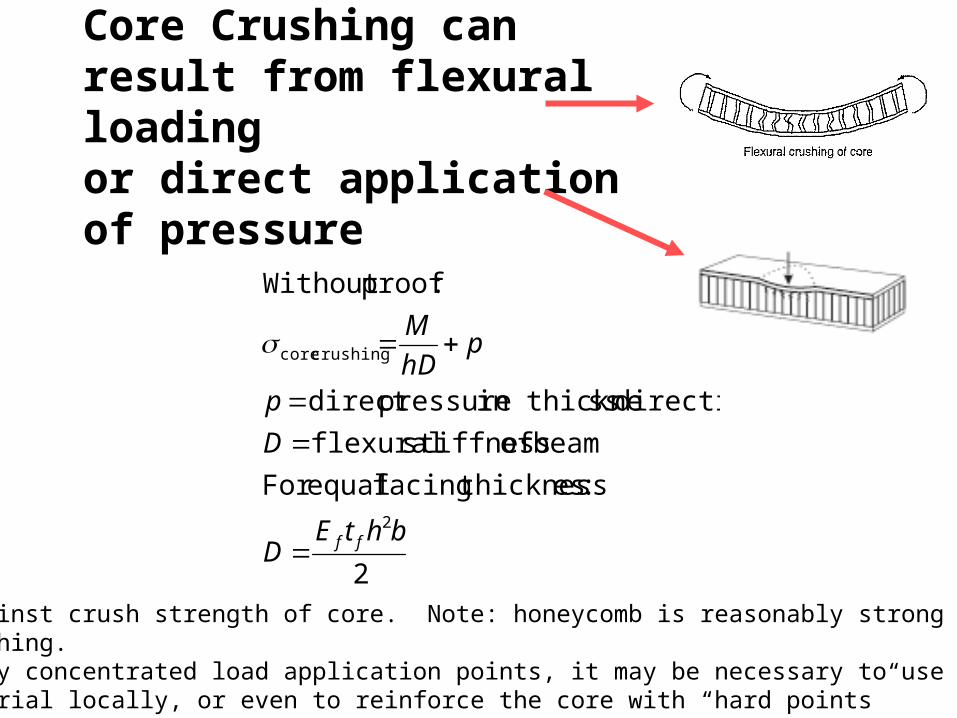
Core Crushing can result from flexural loading or direct application of pressure
2
:es thicknessfacing equalFor
beam of stiffness flexural
direction ssin thickne pressuredirect
:proofWithout
2
crushing core
bhtED
D
p
phD
M
ff
Check against crush strength of core. Note: honeycomb is reasonably strong againstcore crushing.For highly concentrated load application points, it may be necessary to use a stronger core material locally, or even to reinforce the core with “hard points”

Panel Hardpoints for Fasteners
Hexcel

Instability Failures
I am not going to describe the analysis of these modes quantitatively, though they may be significant as should be checked in design.
Some basics:• Shear crimping relates to compression buckling of the core material.• Intracell buckling appears only for honeycomb sandwich panels, and
is a local buckling of the face into or out of the cells. Typically this does not lead to failure of the panel, though it may damage the surface finish or can cause undesirable aerodynamic surface roughness
• Face wrinkling is a short wavelength buckling of a face influenced by either a weak face/core bond, or due to a soft core stiffness. Analysis is difficult, and response is sensitive to initial waviness of the face.

Example
From Hexcel “HexWeb Honeycomb Sandwich Design Technology,” Hexcel Pub. No. AGU 075b

Manufacturing
In MAE 4284 Sandwich Panels and Beams are fabricated using a simple open mold process.
The sandwich structure is “cocured” (meaning all composite parts are laminated and integrated with the core in a single step). This is not necessarily typical of high-quality fabrication.
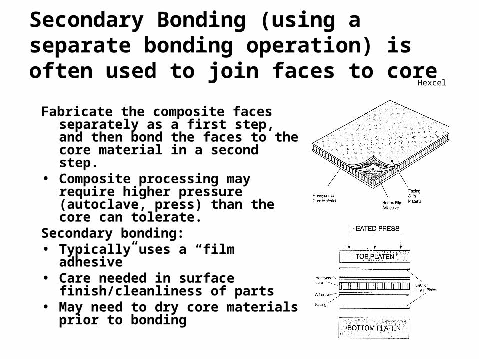
Secondary Bonding (using a separate bonding operation) is often used to join faces to core
Fabricate the composite faces separately as a first step, and then bond the faces to the core material in a second step.
• Composite processing may require higher pressure (autoclave, press) than the core can tolerate.
Secondary bonding:• Typically uses a “film adhesive”• Care needed in surface
finish/cleanliness of parts• May need to dry core materials prior
to bonding
Hexcel
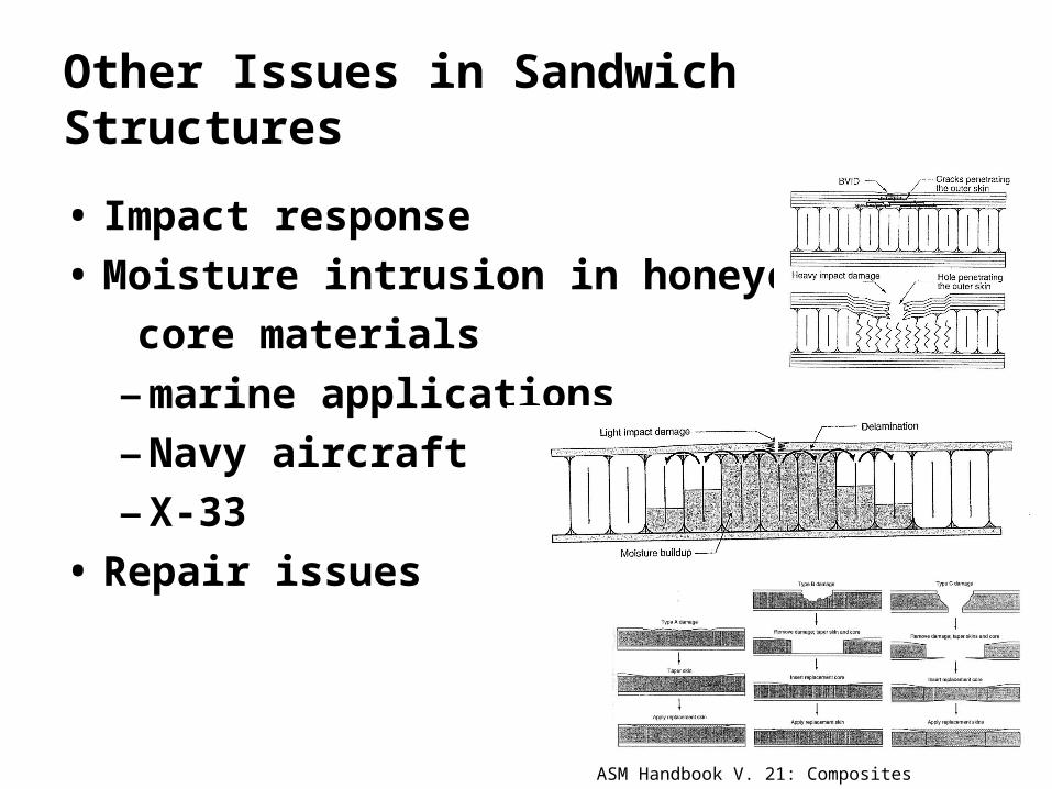
Other Issues in Sandwich Structures
• Impact response
• Moisture intrusion in honeycomb
core materials
–marine applications
–Navy aircraft
–X-33
• Repair issues
ASM Handbook V. 21: Composites


