Contents 4.0 Software Manual v Contents Sequence Edit ... 204 Taper ... Aphex Aural Exciter ...
422
Contents Introduction 1 Introduction .......................................................................... 3 About EOS ......................................................................................... 4 Graphic User Interface ..................................................................... 4 Sequencer and Data Filer ................................................................. 4 Sound Libraries ............................................................................... 4 Sound Storage ................................................................................ 4 Advanced DSP ................................................................................. 4 Built-in Digital Effects ...................................................................... 5 More Digital Processing Features ..................................................... 5 Instant Gratification.............................................................. 6 Power Up! .......................................................................................... 6 Loading a Bank from the Hard Disk ................................................ 7 Loading SoundSprints ...................................................................... 7 Selecting Presets ................................................................................ 8 Lock Button ..................................................................................... 9 Saving ............................................................................................... 10 Arpeggiator ...................................................................................... 11 Keyboard Modes ............................................................................. 14 1 - The Basics 17 Definitions ........................................................................... 19 How Sounds are Organized ........................................................... 19 The Sample ................................................................................... 20 Voices ............................................................................................ 21 The Preset ..................................................................................... 22 SoundSprint .................................................................................. 23 Preset Diagram .............................................................................. 23 Bookmarks .................................................................................... 25 The Bank ....................................................................................... 26 Folders .......................................................................................... 26 The Internal Drive .......................................................................... 27 External Drives .............................................................................. 28 Sample Memory & Preset Memory ............................................... 29 Sound ROM & Sound RAM ........................................................... 29 Five Types of Memory ................................................................... 29 Flash Sound RAM .......................................................................... 30 Sample Numbers ........................................................................... 31 Using Preset Flash Memory ........................................................... 31 Using Sound Flash Memory ........................................................... 32
-
Upload
hoangthuan -
Category
Documents
-
view
232 -
download
0
Transcript of Contents 4.0 Software Manual v Contents Sequence Edit ... 204 Taper ... Aphex Aural Exciter ...

Contents
Introduction 1Introduction .......................................................................... 3
About EOS ......................................................................................... 4Graphic User Interface ..................................................................... 4Sequencer and Data Filer ................................................................. 4Sound Libraries ............................................................................... 4Sound Storage ................................................................................ 4Advanced DSP ................................................................................. 4Built-in Digital Effects ...................................................................... 5More Digital Processing Features ..................................................... 5
Instant Gratification.............................................................. 6Power Up! .......................................................................................... 6
Loading a Bank from the Hard Disk ................................................ 7
Loading SoundSprints ...................................................................... 7
Selecting Presets ................................................................................ 8Lock Button ..................................................................................... 9
Saving ............................................................................................... 10
Arpeggiator ...................................................................................... 11
Keyboard Modes ............................................................................. 14
1 - The Basics 17Definitions........................................................................... 19
How Sounds are Organized ........................................................... 19The Sample ................................................................................... 20Voices ............................................................................................ 21The Preset ..................................................................................... 22SoundSprint .................................................................................. 23Preset Diagram .............................................................................. 23Bookmarks .................................................................................... 25The Bank ....................................................................................... 26Folders .......................................................................................... 26The Internal Drive .......................................................................... 27External Drives .............................................................................. 28
Sample Memory & Preset Memory ............................................... 29Sound ROM & Sound RAM ........................................................... 29Five Types of Memory ................................................................... 29Flash Sound RAM .......................................................................... 30Sample Numbers ........................................................................... 31Using Preset Flash Memory ........................................................... 31Using Sound Flash Memory ........................................................... 32
Contents
Modules ...........................................................................................34
More Definitions ..............................................................................36Saving ...........................................................................................36Default ..........................................................................................36Icons .............................................................................................36The Cursor ....................................................................................37Data Entry Control & Increment/Decrement Buttons .....................37Selecting .......................................................................................37
The Big Re-Cap ................................................................................37
Using The Browser ..........................................................................38
Guided Tours ...................................................................................41Banks, Sequences, Presets & Samples ............................................41Loading a Bank Automatically ........................................................42Loading a Sequence from a Different Bank ....................................43Loading Standard MIDI Files ..........................................................44Saving Banks .................................................................................44Finding Banks, Presets, Samples & Sequences ................................45Naming Banks ...............................................................................46Erasing Banks .................................................................................46Assignable Keys .............................................................................46Recording a Sequence ...................................................................47Arpeggiator Sequencing! ...............................................................50A Practice Sampling Session ...........................................................53Exploring the Preset .......................................................................57Which Voices are Assigned to the Keyboard? .................................58Creating a Link ..............................................................................59
2 - Master Menu 61Overview ............................................................................. 63
Memory Statistics ............................................................................64Master Utilities .................................................................... 65
Assignable Keys ...............................................................................66
Channel Volume ..............................................................................67
Tones ................................................................................................67
Recalibration ....................................................................................68
Test Access .......................................................................................69
About… ............................................................................................70Bank..................................................................................... 71
Erase Bank ........................................................................................71
Name Bank ......................................................................................72
Auto Bank Load ...............................................................................72
Flash Utilities ....................................................................................73Using Sound Flash Memory ...........................................................75
ii E-MU Systems
Contents
Setup ................................................................................... 78Tune .................................................................................................. 79
Tuning Offset ................................................................................ 79Transpose ...................................................................................... 79Audition Key ................................................................................. 80
Input/Output ................................................................................... 80Headroom ..................................................................................... 80Output Boost ................................................................................ 82Output Format .............................................................................. 82ADAT Output Dither ...................................................................... 83Default Clock ................................................................................ 84Word Clock In ............................................................................... 85WC Phase In/Out .......................................................................... 85
Miscellaneous .................................................................................. 86Contrast ........................................................................................ 86Wrap Field Selection ...................................................................... 86Screen Saver .................................................................................. 87Disable Sound ROM ...................................................................... 87Zero Crossing Threshold ............................................................... 88
Undo/Redo Enable .......................................................................... 89
SCSI/Disk .......................................................................................... 90SCSI ID .......................................................................................... 90SCSI Termination On/Off ............................................................... 91Avoid Host on ID ........................................................................... 91Disk Button Goes To: ..................................................................... 92
Import Options ................................................................................ 93Memory Configuration .................................................................. 95
Master Effects ..................................................................... 96Use Master Effects Settings in MultiMode ...................................... 97Master Effects A ............................................................................. 97Master Effects B ............................................................................. 98
Effects Setup .................................................................................... 98Effects Control ............................................................................... 99
Sequence Manage ............................................................ 101MIDI .................................................................................. 102
MIDI Mode .................................................................................... 103Basic Channel .............................................................................. 103MIDI Mode ................................................................................. 103MIDI Device ID ............................................................................ 104Local Control ............................................................................... 105Multimode - MIDI Mix ................................................................ 106
MIDI Controllers ............................................................... 108About MIDI Controllers ............................................................... 108
MIDI Preferences ........................................................................... 110Velocity Curve ............................................................................. 110
EOS 4.0 Software Manual iii
Contents
Controller #7 Sensitivity ...............................................................110Controller #7 Curve .....................................................................111Global Pedal Override ..................................................................111Receive Program Change On/Off .................................................112Send Program Change On/Off ....................................................112Magic Load Preset .......................................................................113
3 - Effects 115Effects ................................................................................ 117
Dual Effects Processor ...................................................................117
The Effects Sends ...........................................................................118Effect B Into Effect A ....................................................................120Three-way Effects Control ............................................................121Effects Programmed in the Preset ................................................122Master Effects ..............................................................................122Using Master Effects Settings in Multimode .................................123Using the Effects Channel Settings in Multimode .........................124Effects Bypass ..............................................................................125
Effect Descriptions .........................................................................126A EFFECT TYPES ...........................................................................126B EFFECT TYPES ...........................................................................126Reverb .........................................................................................127Chorus ........................................................................................128Doubling .....................................................................................128Slapback ......................................................................................128Stereo Flanger .............................................................................128Delay ...........................................................................................129Stereo Delay ................................................................................129Panning Delay .............................................................................129Dual Tap ......................................................................................129Vibrato ........................................................................................129Distortion ....................................................................................129
4 - Sequencer 131Sequence Manage............................................................. 133
Recording MIDI SysEx ..................................................................136Standard MIDI files ......................................................................136Name Sequence ..........................................................................137Export .........................................................................................138
Transport Controls............................................................ 139Sequencer Utilities ............................................................ 140
Erase ............................................................................................140Copy Sequence ...........................................................................141Sequencer Memory .....................................................................141Jukebox .......................................................................................142Sequence Edit ..............................................................................142
iv E-MU Systems
Contents
Sequence Edit ................................................................... 143The Sequence Edit Screen ............................................................ 144
Track Mode ................................................................................. 144Track Numbers ............................................................................ 144Counter Display .......................................................................... 144Tempo Display ............................................................................ 144Track ‘ Preset ............................................................................... 144MIDI Channel Modes .................................................................. 145Volume - Pan - Submix ................................................................ 145The Initial Track State Screen ....................................................... 145Initial Tempo ............................................................................... 146Cut/Copy .................................................................................... 146
Editing: Cut, Copy & Paste ............................................... 147Cut/Copy/Erase ......................................................................... 147Note Erase ................................................................................... 148Paste ........................................................................................... 150Track Delete ................................................................................ 152Track Copy .................................................................................. 152UNDO! (REDO!) .......................................................................... 153
Tools.................................................................................. 154Quantize ........................................................................................ 154
Transpose ....................................................................................... 156
Sequence Velocity ......................................................................... 157
Channelize ..................................................................................... 158
Channel Extract ............................................................................. 159Setup ................................................................................. 160
Metronome .................................................................................... 161
Sequence Clock ............................................................................. 162
Sequence Input ............................................................................. 164
Sequence Record ........................................................................... 165
Sequence Loop .............................................................................. 166
Transport ........................................................................................ 167Received MMC Commands ......................................................... 168
Locate ............................................................................................. 169
5 - Sample Manage 171Overview ........................................................................... 173
Sample Utilities .............................................................................. 174Erase Sample ............................................................................... 174Copy Sample ............................................................................... 175Sample Dump ............................................................................. 175Defragment Memory .................................................................. 177
EOS 4.0 Software Manual v
Contents
Name Sample ................................................................................178
New Sample ...................................................................................178Threshold ....................................................................................179Input Channels ............................................................................179Sampling Source & Rate ..............................................................179Dither ..........................................................................................180ADC Gain ....................................................................................181Sample Length ............................................................................182Arm Sample Trigger .....................................................................182Force Sample Trigger ...................................................................183Keyboard Sample Trigger .............................................................183Monitor On/Off ...........................................................................184
Automatic Parameters ...................................................................184Automatic Digital Signal Processing Operations ...........................184Auto-Placement Parameters .........................................................186
Place Sample ..................................................................................188
Export Sample ...............................................................................189
Get Info ..........................................................................................190
6 - Sample Edit 191Sample Edit ....................................................................... 193
Background: The Scrub Wheel .....................................................194
Background: Using Cut, Copy, Paste and Undo .........................195
Background: About Looping ........................................................196How Looping Works ....................................................................196Auto Correlation ..........................................................................196Creating Attack & Decay Characteristics for the Looped Portion ..197Loop Compression ......................................................................198Crossfade Looping .......................................................................198Zero Crossing ..............................................................................198
Utilities .............................................................................. 199Cut Section .................................................................................199Copy Section ...............................................................................201Paste Section ...............................................................................202Truncation ...................................................................................204Taper ...........................................................................................205
Tools 1 ............................................................................... 207Loop ...............................................................................................207
Loop Type ......................................................................................210
Digital Tuning ................................................................................211
Sample Rate Convert ....................................................................212
Sample Calculator .........................................................................213
vi E-MU Systems
Contents
Tools 2............................................................................... 214DC Filter ......................................................................................... 214
Swap Left & Right ......................................................................... 215
Stereo <-> Mono ........................................................................... 216
Reverse Section .............................................................................. 216
Sample Integrity ............................................................................ 217Tools 3............................................................................... 218
Gain Change .............................................................................. 218
Compressor ................................................................................... 221
Using the Digital Compressor ...................................................... 224Limiter ........................................................................................ 224Musical Compression (e.g. Guitar) .............................................. 224Noise Reduction .......................................................................... 224
Parametric Equalizer ..................................................................... 225
FIR (Phase Linear Filter) ................................................................. 227
Aphex Aural Exciter ....................................................................... 229Tools 4............................................................................... 230
Transform Multiplication .............................................................. 231
Doppler .......................................................................................... 232
Time Compression ........................................................................ 234
Pitch Change ................................................................................. 235
Bit Converter ................................................................................. 236
Beat Munger .................................................................................. 237Beat Munger Controls ................................................................. 238
Undo.................................................................................. 240
7 - Preset Manage 243Preset Manage .................................................................. 245
Utilities ........................................................................................... 246Erase Preset ................................................................................. 246Dump Preset ............................................................................... 246
Name Preset .................................................................................. 247
New Preset ..................................................................................... 247
Copy Preset .................................................................................... 248
Export Preset ................................................................................. 249
Get Info .......................................................................................... 250
EOS 4.0 Software Manual vii
Contents
8 - Preset Edit 251Synthesizer Basics ............................................................. 253
Editing Presets ...............................................................................253
Modulation ....................................................................................254Modulation Sources .....................................................................255Modulation Cords .......................................................................256
Envelope Generators .....................................................................257
Low Frequency Oscillators (LFOs) ................................................258
Random Sources ............................................................................259
Clock Modulation ..........................................................................260
Modulation Destinations ..............................................................262
Modulation Processors ..................................................................263Modulation Processors .................................................................264
Dynamic Filters.................................................................. 269Dynamic Filters ..............................................................................269
What is a Filter? ...........................................................................270Parametric Filters .........................................................................273The Z-Plane Filter .........................................................................273
Selecting Voices, Samples & Groups ................................ 275Selecting from the Preset Editor Windows ..................................275
Selecting All Voices ........................................................................276Selecting Voices from the Dynamic Processing Level ....................276Selecting Voices from the Voice Select Screen ..............................276
Groups............................................................................... 277Preset Editor...................................................................... 278PRESET EDIT - Global ........................................................ 281
Global Editor ..................................................................................281Edit All .........................................................................................281
Preset Effects A.................................................................. 282Effects Programmed in the Preset ................................................283
Effect ...........................................................................................284Decay Time .................................................................................285HF Damping ................................................................................285FX Amounts .................................................................................285FX B Through FX A ......................................................................286
Preset Effects B.................................................................. 287Effect B ...........................................................................................287
Feedback Amount .......................................................................288LFO Rate ......................................................................................289Delay Time ..................................................................................289FX Amounts .................................................................................290
Preset Edit - Links .............................................................. 291
viii E-MU Systems
Contents
Main Controls ................................................................................ 291
Link Type ........................................................................................ 292
Link Volume ................................................................................... 292
Link Pan .......................................................................................... 293
Link Transpose ............................................................................... 293
Link Fine Tuning ............................................................................ 294Link Utilities ...................................................................... 295
New Link ........................................................................................ 295
Copy Link ....................................................................................... 296
Delete Link ..................................................................................... 296
Subsume Link ................................................................................ 297Links - Key Window........................................................... 298
Key Window Controls .................................................................. 298
Keyboard & Velocity Ranges ........................................................ 299Links - Velocity Window ................................................... 300
Velocity Window Controls ............................................................ 300
Velocity Range ............................................................................... 301Links - MIDI Filters ............................................................ 302
MIDI Filter Window Controls ....................................................... 302Preset Edit - Voices ........................................................... 304
Voices - Main Controls .................................................................. 304
Voice Utilities ................................................................................. 305New Voice ................................................................................... 305Copy Voice .................................................................................. 305Delete Voice ................................................................................ 306Split Voice ................................................................................... 306Solo Voice ................................................................................... 307
Sample Zone ..................................................................... 308New Sample Zone ........................................................................ 308
Get Multisample ............................................................................ 309
Delete Sample Zone ..................................................................... 309
Combine ........................................................................................ 310
Expand... ........................................................................................ 311Voices - Key Window ........................................................ 312
Key Window Controls ................................................................... 312
Keyboard Ranges .......................................................................... 313Voices -Velocity Window .................................................. 316
Velocity Window Controls ............................................................ 316
Velocity Range ............................................................................... 317
EOS 4.0 Software Manual ix
Contents
Voices - Realtime Window ................................................ 319Realtime Window Controls ...........................................................319
Preset Edit - Dynamic Processing Level ............................ 322Utilities .............................................................................. 325
Voice Select ....................................................................................326Function Keys ..............................................................................326The Isolate Key: ...........................................................................328
Copy Voice(s) .................................................................................328
Delete Voice(s) ...............................................................................330
Automatic Voice Selection ............................................................331
Set ...................................................................................................331
Solo Voice .......................................................................................331Voice Tuning, Modifiers & Setup ............................................................. 332
Key Transpose ................................................................................333
Coarse Tuning ................................................................................333
Fine Tuning ....................................................................................334
Non-transpose Mode ....................................................................334
Chorus Amount .............................................................................335
Delay ...............................................................................................336
Start Offset .....................................................................................336
Glide Rate & Curve .......................................................................337
Solo Modes ....................................................................................338
Latch Mode ....................................................................................339
Assign Group .................................................................................340Amplifier/Filter.................................................................. 341
Amplifier Parameters .....................................................................341
Amplifier Envelope ........................................................................342
Filter Parameters ............................................................................343FILTER TYPES ...............................................................................343
Filter Envelope ...............................................................................347LFO/Auxiliary Envelope..................................................... 348
Lag Processors ...............................................................................349
Auxiliary Envelope .........................................................................350Cords ................................................................................. 351
Sample Retrigger ...........................................................................353
x E-MU Systems
Contents
9 - Disk Menu 355Disk Menu ......................................................................... 357
Disk Browser .................................................................................. 357Disk.................................................................................... 361
Disk Utilities ................................................................................... 361
Mount Drives ................................................................................. 362
Copy System .................................................................................. 362
Format Disk .................................................................................... 363
Low Level Format .......................................................................... 364
Backup ........................................................................................... 364
Load Bank ...................................................................................... 366
Save Bank ....................................................................................... 367
View… ............................................................................................ 367
Info, Lock Drive, & Sleep .............................................................. 368Lock ............................................................................................ 368Sleep ........................................................................................... 368
Folder ................................................................................ 369Folder Utilities ................................................................................ 369
New ................................................................................................ 369
Delete ............................................................................................. 370
Rename .......................................................................................... 370
Find… ............................................................................................. 370
View ................................................................................................ 371
Info… ............................................................................................. 371Bank................................................................................... 372
Bank Utilities .................................................................................. 372
Delete ............................................................................................. 372
Name ............................................................................................. 373
Find… ............................................................................................. 373
Load Bank ...................................................................................... 374
Save Bank ....................................................................................... 374
View ................................................................................................ 375
Info… ............................................................................................. 375Preset ................................................................................ 376
Preset Utilities ................................................................................ 376
Soundsprint™ ................................................................................ 376Bookmarks .................................................................................. 378
EOS 4.0 Software Manual xi

Contents
Find… .............................................................................................379
Load Preset .....................................................................................380
View ................................................................................................380
Info… ..............................................................................................380Sample............................................................................... 381
Sample Utilities ..............................................................................381Find... ..........................................................................................381
View ................................................................................................382
Load Sample ..................................................................................382
Load .WAV & AIFF Files .................................................................383
Audition ..........................................................................................383
Info… ..............................................................................................383Sequence ........................................................................... 384
Sequence Utility .............................................................................384
Find… .............................................................................................385
View ................................................................................................385
Load Sequence ..............................................................................385
Info… ..............................................................................................386
10 - Appendix 387SCSI ................................................................................... 389
Why Use SCSI? ...............................................................................389
The SCSI Bus ..................................................................................389ID Numbers .................................................................................389
Types of SCSI Cables .....................................................................390Terminating SCSI Cables ..............................................................390
SCSI Problems ................................................................................391
Sample Transfers Via SMDI ...........................................................392
Using Multiple Samplers on the SCSI Bus ...................................393Menu Maps ....................................................................... 394
Menu Maps ....................................................................................394
Menu Maps ....................................................................................395
Menu Maps ....................................................................................396MIDI................................................................................... 397
MIDI Implementation Chart ........................................................397Notes: ................................................................................ 398
Index 399
xii E-MU Systems

Introduction

Introduction
2 E-MU Systems

Introduction
This is the operation manual for E-mu Operating System (EOS). EOS is the operating system in several E-mu products, including: E-IV, e-64, E4K, E-6400, E4X, E-Synth and the E4 Ultra series. The same EOS software is loaded into each of these machines. For the sake of simplicity, we refer to all these products as “the Emulator” when we talk about them in this manual (unless, of course, there is an issue involving a particular product, then we will be specific).
Your Emulator is a special purpose sound computer and like all computers, can be thought of as having two main components:
1.
The physical machine with the buttons, keys, gadgets, that generates sound and;
2.
The EOS software that tells the hardware what to do.
This manual describes how to use EOS to get the most from your Emulator. The various functions of EOS are organized in this manual by their module. Screen displays and step-by-step instructions are described for all aspects of use and operation. Notes in the margin highlight important points or give useful operational tips which might not be readily apparent.
If you are unfamiliar with samplers and synthesizers in general, you may need more information than this manual provides. We suggest that you read some of the many books and magazines on the subject of music synthesis. This will help you to get the most out of this extremely powerful instrument.
Important Upgrade Information
The features and functions of EOS are enhanced and upgraded periodically. Please take a moment now to read the E-mu Systems warranty and fill out and send in your warranty registration card. We NEED your mailing address in order to keep you informed about upgrades and manual revisions.
EOS 4.0 Software Manual 3
IntroductionAbout EOS
About EOS
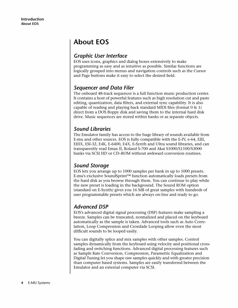
Graphic User Interface
EOS uses icons, graphics and dialog boxes extensively to make programming as easy and as intuitive as possible. Similar functions are logically grouped into menus and navigation controls such as the Cursor and Page buttons make it easy to select the desired field.
Sequencer and Data Filer
The onboard 48-track sequencer is a full function music production center. It contains a host of powerful features such as high resolution cut and paste editing, quantization, data filters, and external sync capability. It is also capable of reading and playing back standard MIDI files (format 0 & 1) direct from a DOS floppy disk and saving them to the internal hard disk drive. Music sequences are stored within banks or as separate objects.
Sound Libraries
The Emulator family has access to the huge library of sounds available from E-mu and other sources. EOS is fully compatible with the E-IV, e-64, EIII, EIIIX, ESI-32, E4K, E-6400, E4X, E-Synth and Ultra sound libraries, and can transparently read Emax II, Roland S-700 and Akai S1000/S1100/S3000 banks via SCSI HD or CD–ROM without awkward conversion routines.
Sound Storage
EOS lets you arrange up to 1000 samples per bank in up to 1000 presets. E-mu's exclusive SoundSprint™ function automatically loads presets from the hard disk as you browse through them. You can continue to play while the new preset is loading in the background. The Sound ROM option (standard on E-Synth) gives you 16 MB of great samples with hundreds of user programmable presets which are always on-line and ready to go.
Advanced DSP
EOS’s advanced digital signal processing (DSP) features make sampling a breeze. Samples can be truncated, normalized and placed on the keyboard automatically as the sample is taken. Advanced tools such as Auto Corre-lation, Loop Compression and Crossfade Looping allow even the most difficult sounds to be looped easily.
You can digitally splice and mix samples with other samples. Control samples dynamically from the keyboard using velocity and positional cross-fading and switching functions. Advanced digital processing features such as Sample Rate Conversion, Compression, Parametric Equalization and Digital Tuning let you shape raw samples quickly and with greater precision than computer based systems. Samples are easily transferred between the Emulator and an external computer via SCSI.
4 E-MU Systems
IntroductionAbout EOS
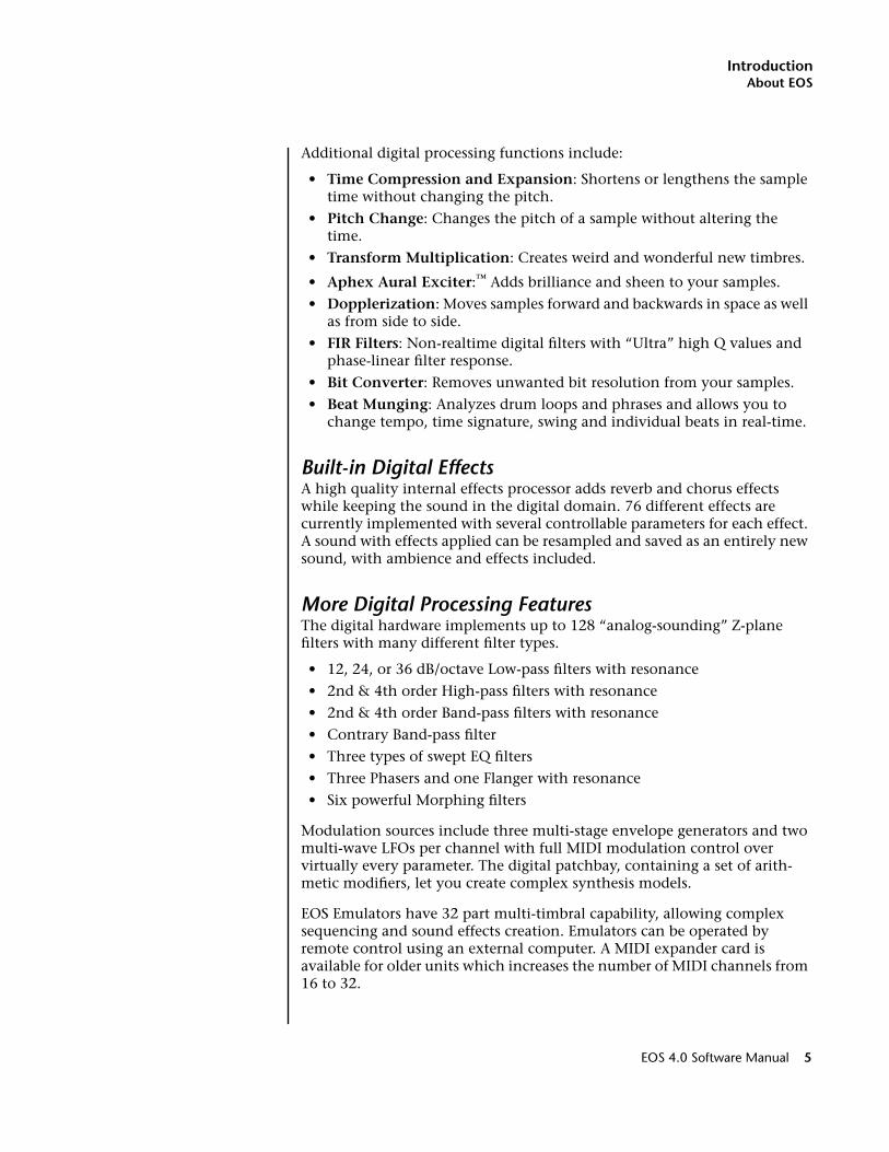
Additional digital processing functions include:
•
Time Compression and Expansion
: Shortens or lengthens the sample time without changing the pitch.
•
Pitch Change
: Changes the pitch of a sample without altering the time.
•
Transform Multiplication
: Creates weird and wonderful new timbres.
•
Aphex Aural Exciter
:
™
Adds brilliance and sheen to your samples.
•
Dopplerization
: Moves samples forward and backwards in space as well as from side to side.
•
FIR Filters
: Non-realtime digital filters with “Ultra” high Q values and phase-linear filter response.
•
Bit Converter
: Removes unwanted bit resolution from your samples.
•
Beat Munging
: Analyzes drum loops and phrases and allows you to change tempo, time signature, swing and individual beats in real-time.
Built-in Digital Effects
A high quality internal effects processor adds reverb and chorus effects while keeping the sound in the digital domain. 76 different effects are currently implemented with several controllable parameters for each effect. A sound with effects applied can be resampled and saved as an entirely new sound, with ambience and effects included.
More Digital Processing Features
The digital hardware implements up to 128 “analog-sounding” Z-plane filters with many different filter types.
•
12, 24, or 36 dB/octave Low-pass filters with resonance
•
2nd & 4th order High-pass filters with resonance
•
2nd & 4th order Band-pass filters with resonance
•
Contrary Band-pass filter
•
Three types of swept EQ filters
•
Three Phasers and one Flanger with resonance
•
Six powerful Morphing filters
Modulation sources include three multi-stage envelope generators and two multi-wave LFOs per channel with full MIDI modulation control over virtually every parameter. The digital patchbay, containing a set of arith-metic modifiers, let you create complex synthesis models.
EOS Emulators have 32 part multi-timbral capability, allowing complex sequencing and sound effects creation. Emulators can be operated by remote control using an external computer. A MIDI expander card is available for older units which increases the number of MIDI channels from 16 to 32.
EOS 4.0 Software Manual 5
IntroductionPower Up!
Instant Gratification
This section is designed to get you playing sounds in the shortest amount of time and provides only a partial explanation of disk operations. For more complete instructions, see “Disk Menu” on page 355.
Power Up!
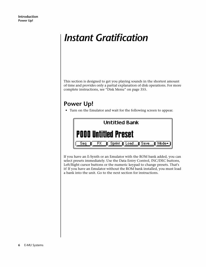
•
Turn on the Emulator and wait for the following screen to appear.
If you have an E-Synth or an Emulator with the ROM bank added, you can select presets immediately. Use the Data Entry Control, INC/DEC buttons, Left/Right cursor buttons or the numeric keypad to change presets. That's it! If you have an Emulator without the ROM bank installed, you must load a bank into the unit. Go to the next section for instructions.
6 E-MU Systems
IntroductionLoading a Bank from the Hard Disk
Loading a Bank from the Hard Disk
Loading a bank of sounds makes an entire collection of different presets immediately available.
v
To Load a Bank from the Hard Disk:
1.
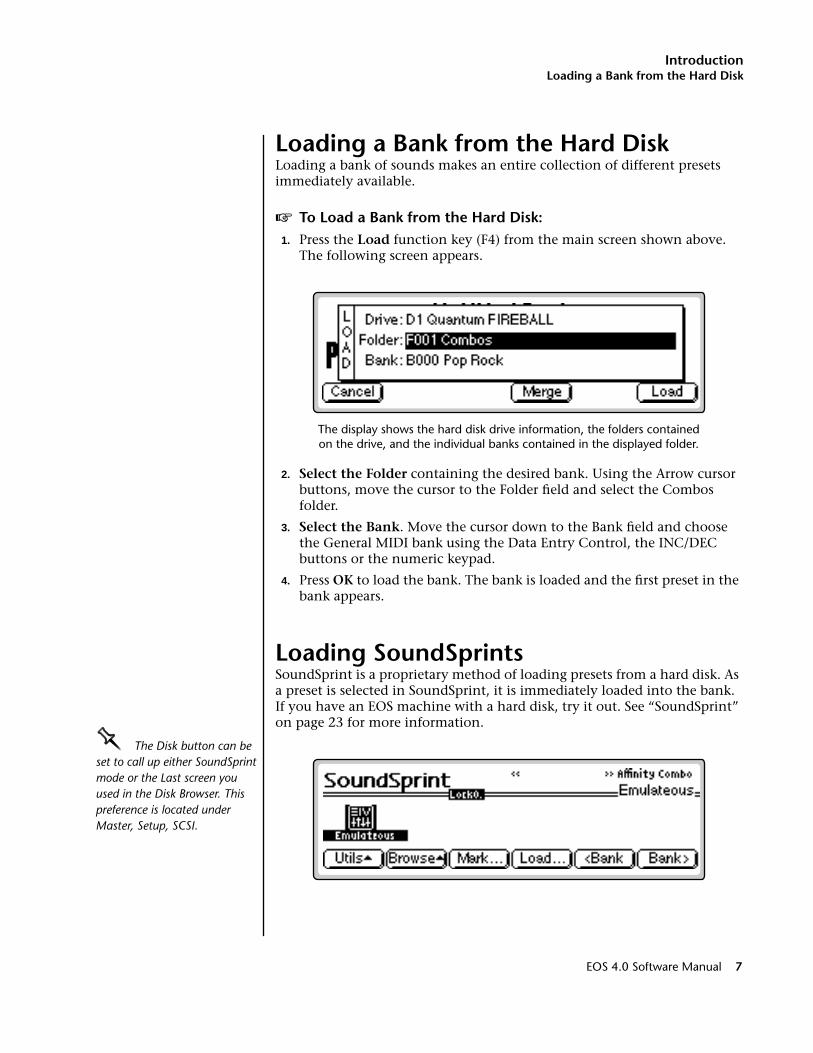
Press the
Load
function key (F4) from the main screen shown above. The following screen appears.
The display shows the hard disk drive information, the folders contained on the drive, and the individual banks contained in the displayed folder.
2.
Select the Folder
containing the desired bank. Using the Arrow cursor buttons, move the cursor to the Folder field and select the Combos folder.
3.
Select the Bank
. Move the cursor down to the Bank field and choose the General MIDI bank using the Data Entry Control, the INC/DEC buttons or the numeric keypad.
4.
Press
OK
to load the bank. The bank is loaded and the first preset in the bank appears.
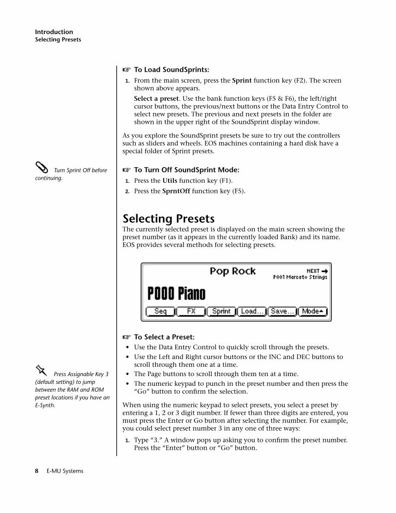
Loading SoundSprints
SoundSprint is a proprietary method of loading presets from a hard disk. As a preset is selected in SoundSprint, it is immediately loaded into the bank. If you have an EOS machine with a hard disk, try it out. See “SoundSprint” on page 23 for more information.
OOOO
The Disk button can be set to call up either SoundSprint mode or the Last screen you used in the Disk Browser. This preference is located under Master, Setup, SCSI.
EOS 4.0 Software Manual 7
Introduction
Selecting Presets
v To Load SoundSprints:1. From the main screen, press the Sprint function key (F2). The screen
shown above appears.
Select a preset. Use the bank function keys (F5 & F6), the left/right cursor buttons, the previous/next buttons or the Data Entry Control to select new presets. The previous and next presets in the folder are shown in the upper right of the SoundSprint display window.
As you explore the SoundSprint presets be sure to try out the controllers such as sliders and wheels. EOS machines containing a hard disk have a special folder of Sprint presets.
Turn Sprint Off before continuing.
v To Turn Off SoundSprint Mode:1. Press the Utils function key (F1).
2. Press the SprntOff function key (F5).
Selecting PresetsThe currently selected preset is displayed on the main screen showing the preset number (as it appears in the currently loaded Bank) and its name. EOS provides several methods for selecting presets.
v To Select a Preset:• Use the Data Entry Control to quickly scroll through the presets.
• Use the Left and Right cursor buttons or the INC and DEC buttons to scroll through them one at a time.
OOOO Press Assignable Key 3 (default setting) to jump between the RAM and ROM preset locations if you have an E-Synth.
• The Page buttons to scroll through them ten at a time.
• The numeric keypad to punch in the preset number and then press the “Go” button to confirm the selection.
When using the numeric keypad to select presets, you select a preset by entering a 1, 2 or 3 digit number. If fewer than three digits are entered, you must press the Enter or Go button after selecting the number. For example, you could select preset number 3 in any one of three ways:
1. Type “3.” A window pops up asking you to confirm the preset number. Press the “Enter” button or “Go” button.
8 E-MU Systems
IntroductionSelecting Presets
2. Type “03.” A window pops up asking you to confirm the preset number. Press the “Enter” button or “Go” button.
3. Type “003.” (You do not need to press the “Enter” button or “Go” button when entering all three digits of the preset number. Because there are only three possible digits, EOS knows that you’re done.)
OOOO The more sound RAM you have in the unit, the larger the bank size can be and the more presets you can have in the bank at once.
Presets are contained in the bank you loaded earlier so they are instantly accessible when selected, unlike SoundSprint presets, which take a second or two to load from the hard disk.
The next and previous presets are displayed in the upper corners of the screen. The next preset is displayed in the upper right hand corner, the previous preset is shown in the upper left hand corner.
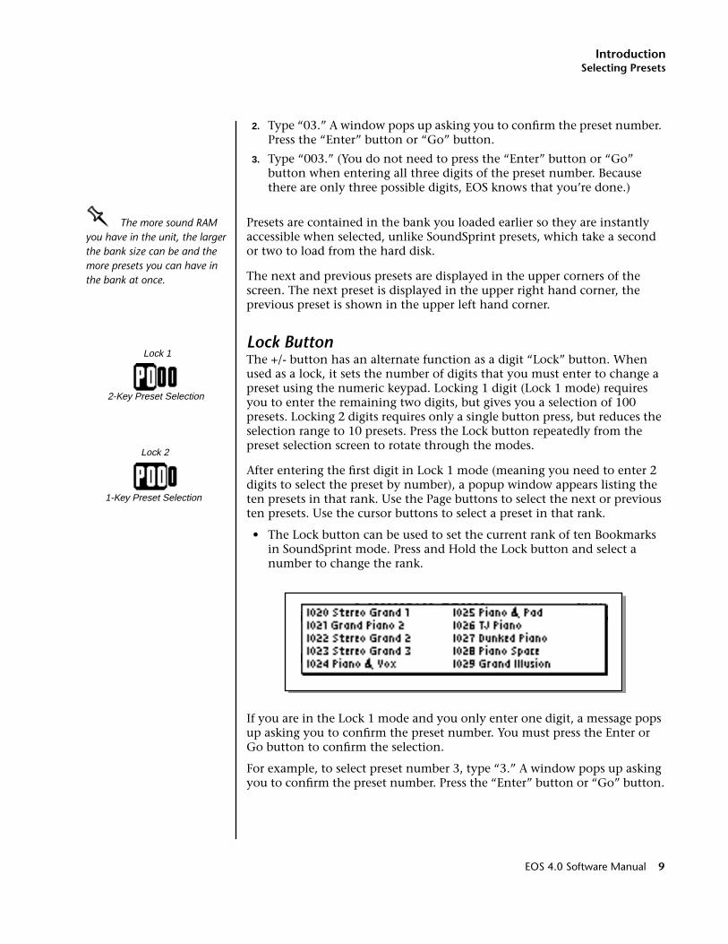
Lock ButtonThe +/- button has an alternate function as a digit “Lock” button. When used as a lock, it sets the number of digits that you must enter to change a preset using the numeric keypad. Locking 1 digit (Lock 1 mode) requires you to enter the remaining two digits, but gives you a selection of 100 presets. Locking 2 digits requires only a single button press, but reduces the selection range to 10 presets. Press the Lock button repeatedly from the preset selection screen to rotate through the modes.
After entering the first digit in Lock 1 mode (meaning you need to enter 2 digits to select the preset by number), a popup window appears listing the ten presets in that rank. Use the Page buttons to select the next or previous ten presets. Use the cursor buttons to select a preset in that rank.
• The Lock button can be used to set the current rank of ten Bookmarks in SoundSprint mode. Press and Hold the Lock button and select a number to change the rank.
If you are in the Lock 1 mode and you only enter one digit, a message pops up asking you to confirm the preset number. You must press the Enter or Go button to confirm the selection.
For example, to select preset number 3, type “3.” A window pops up asking you to confirm the preset number. Press the “Enter” button or “Go” button.
Lock 1
2-Key Preset Selection
Lock 2
1-Key Preset Selection
EOS 4.0 Software Manual 9
IntroductionSaving
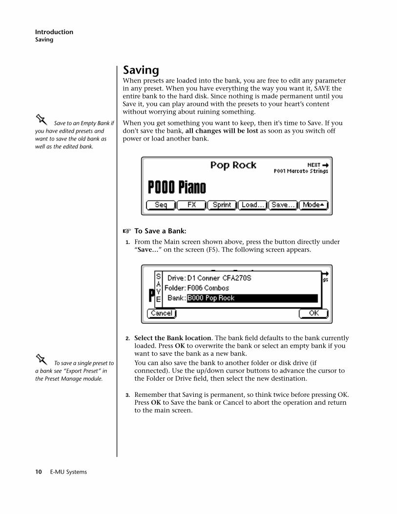
SavingWhen presets are loaded into the bank, you are free to edit any parameter in any preset. When you have everything the way you want it, SAVE the entire bank to the hard disk. Since nothing is made permanent until you Save it, you can play around with the presets to your heart’s content without worrying about ruining something.
OOOO Save to an Empty Bank if you have edited presets and want to save the old bank as well as the edited bank.
When you get something you want to keep, then it's time to Save. If you don't save the bank, all changes will be lost as soon as you switch off power or load another bank.
v To Save a Bank:1. From the Main screen shown above, press the button directly under
“Save…” on the screen (F5). The following screen appears.
2. Select the Bank location. The bank field defaults to the bank currently loaded. Press OK to overwrite the bank or select an empty bank if you want to save the bank as a new bank.
OOOO To save a single preset to a bank see “Export Preset” in the Preset Manage module.
You can also save the bank to another folder or disk drive (if connected). Use the up/down cursor buttons to advance the cursor to the Folder or Drive field, then select the new destination.
3. Remember that Saving is permanent, so think twice before pressing OK. Press OK to Save the bank or Cancel to abort the operation and return to the main screen.
10 E-MU Systems

IntroductionArpeggiator
ArpeggiatorOOOO The arpeggiated notes can be recorded into the sequencer and are transmitted on the MIDI Out port.
An arpeggiator moves a pattern of notes sequentially over a range of the keyboard. EOS provides a performance-oriented arpeggiator which is powerful, yet quick and easy to use. It has several features including tap tempo, octave extension, note value divisor and control over how the extensions are played (up, down, or up and down or random). The arpeg-giator plays on the Basic Channel and remembers the order of played notes.
v To Access the Arpeggiator:1. From the main preset selection screen, press the Mode function key
(F6). A new set of function keys appears.
2. Press the Arp function key (F5). The arpeggiator will be enabled and the function keys now control the arpeggiator functions.
OOOO The arpeggiator continues playing on the current MIDI channel if you switch to Multi mode.
Octave Extension. The extension control shifts the arpeggio up the specified number of octaves each time the pattern is repeated. For example, suppose you played C2 with an Octave Extension value of 2. The arpeg-giator advances the pattern 2 octaves in the direction specified. The extension can be set from 0-3 octaves.
v To Set the Octave Extension:• Press the Octave Extension button (F2) to toggle between values.
OctaveExtend
Direction NoteDivision
Tempo GoBack
Arp Off
12 3 45 6 78 9
Extend 1
Back
PlayedExtend 2
2-oct Extension, Direction Up
None 1 Oct 2 Oct 3 Oct
EOS 4.0 Software Manual 11
IntroductionArpeggiator
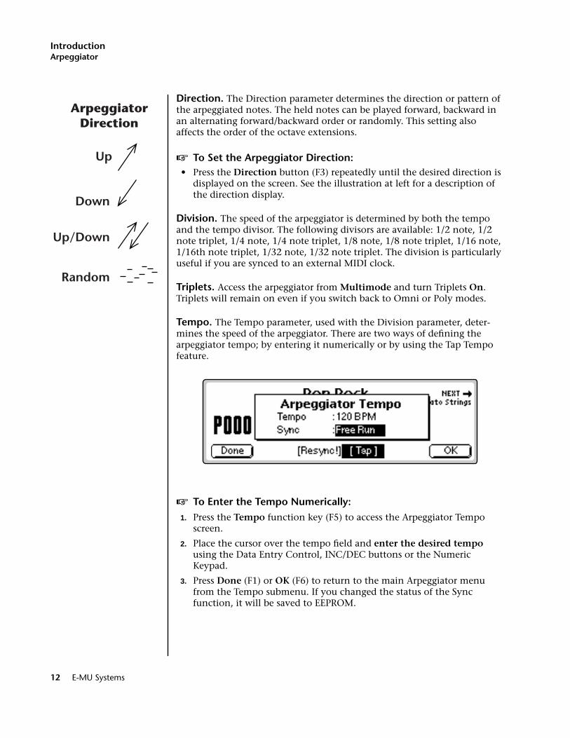
Direction. The Direction parameter determines the direction or pattern of the arpeggiated notes. The held notes can be played forward, backward in an alternating forward/backward order or randomly. This setting also affects the order of the octave extensions.
v To Set the Arpeggiator Direction:• Press the Direction button (F3) repeatedly until the desired direction is
displayed on the screen. See the illustration at left for a description of the direction display.
Division. The speed of the arpeggiator is determined by both the tempo and the tempo divisor. The following divisors are available: 1/2 note, 1/2 note triplet, 1/4 note, 1/4 note triplet, 1/8 note, 1/8 note triplet, 1/16 note, 1/16th note triplet, 1/32 note, 1/32 note triplet. The division is particularly useful if you are synced to an external MIDI clock.
Triplets. Access the arpeggiator from Multimode and turn Triplets On. Triplets will remain on even if you switch back to Omni or Poly modes.
Tempo. The Tempo parameter, used with the Division parameter, deter-mines the speed of the arpeggiator. There are two ways of defining the arpeggiator tempo; by entering it numerically or by using the Tap Tempo feature.
v To Enter the Tempo Numerically:1. Press the Tempo function key (F5) to access the Arpeggiator Tempo
screen.
2. Place the cursor over the tempo field and enter the desired tempo using the Data Entry Control, INC/DEC buttons or the Numeric Keypad.
3. Press Done (F1) or OK (F6) to return to the main Arpeggiator menu from the Tempo submenu. If you changed the status of the Sync function, it will be saved to EEPROM.
Up
Down
Up/Down
Random
ArpeggiatorDirection
12 E-MU Systems
IntroductionArpeggiator
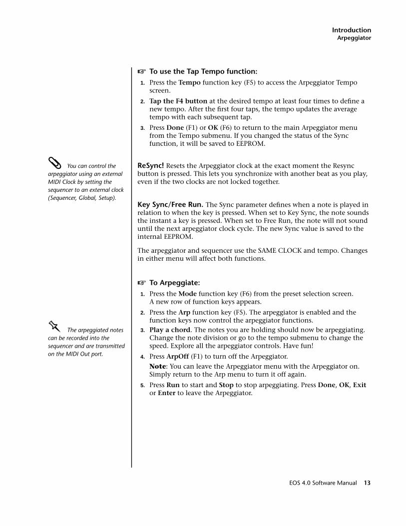
v To use the Tap Tempo function:1. Press the Tempo function key (F5) to access the Arpeggiator Tempo
screen.
2. Tap the F4 button at the desired tempo at least four times to define a new tempo. After the first four taps, the tempo updates the average tempo with each subsequent tap.
3. Press Done (F1) or OK (F6) to return to the main Arpeggiator menu from the Tempo submenu. If you changed the status of the Sync function, it will be saved to EEPROM.
You can control the arpeggiator using an external MIDI Clock by setting the sequencer to an external clock (Sequencer, Global, Setup).
ReSync! Resets the Arpeggiator clock at the exact moment the Resync button is pressed. This lets you synchronize with another beat as you play, even if the two clocks are not locked together.
Key Sync/Free Run. The Sync parameter defines when a note is played in relation to when the key is pressed. When set to Key Sync, the note sounds the instant a key is pressed. When set to Free Run, the note will not sound until the next arpeggiator clock cycle. The new Sync value is saved to the internal EEPROM.
The arpeggiator and sequencer use the SAME CLOCK and tempo. Changes in either menu will affect both functions.
v To Arpeggiate:1. Press the Mode function key (F6) from the preset selection screen.
A new row of function keys appears.
2. Press the Arp function key (F5). The arpeggiator is enabled and the function keys now control the arpeggiator functions.
OOOO The arpeggiated notes can be recorded into the sequencer and are transmitted on the MIDI Out port.
3. Play a chord. The notes you are holding should now be arpeggiating. Change the note division or go to the tempo submenu to change the speed. Explore all the arpeggiator controls. Have fun!
4. Press ArpOff (F1) to turn off the Arpeggiator.
Note: You can leave the Arpeggiator menu with the Arpeggiator on. Simply return to the Arp menu to turn it off again.
5. Press Run to start and Stop to stop arpeggiating. Press Done, OK, Exit or Enter to leave the Arpeggiator.
EOS 4.0 Software Manual 13
IntroductionKeyboard Modes
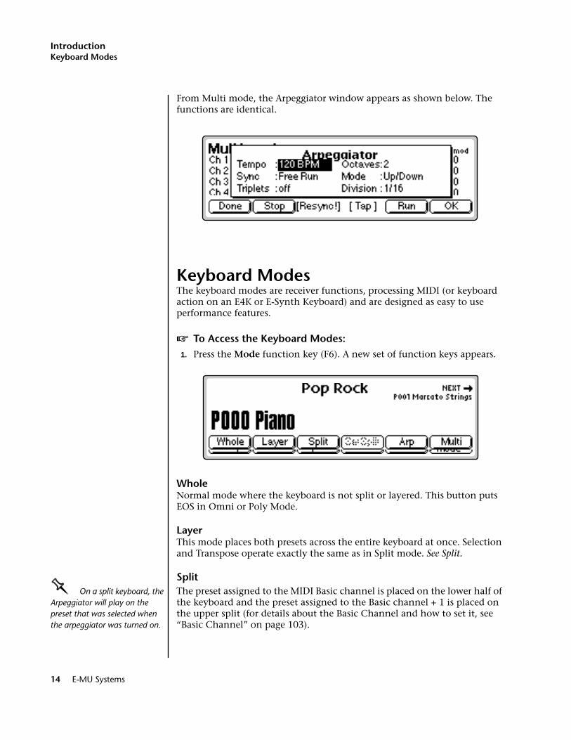
From Multi mode, the Arpeggiator window appears as shown below. The functions are identical.
Keyboard ModesThe keyboard modes are receiver functions, processing MIDI (or keyboard action on an E4K or E-Synth Keyboard) and are designed as easy to use performance features.
v To Access the Keyboard Modes:1. Press the Mode function key (F6). A new set of function keys appears.
WholeNormal mode where the keyboard is not split or layered. This button puts EOS in Omni or Poly Mode.
LayerThis mode places both presets across the entire keyboard at once. Selection and Transpose operate exactly the same as in Split mode. See Split.
SplitOOOO On a split keyboard, the Arpeggiator will play on the preset that was selected when the arpeggiator was turned on.
The preset assigned to the MIDI Basic channel is placed on the lower half of the keyboard and the preset assigned to the Basic channel + 1 is placed on the upper split (for details about the Basic Channel and how to set it, see “Basic Channel” on page 103).
14 E-MU Systems

IntroductionKeyboard Modes
v To Set the Keyboard Split Point:
1. Press the Mode button (F6) from the main preset screen. The Keyboard submenu appears.
2. Press the SetSplit function key (F4). The display asks you to play a key.
3. Play a key on the keyboard you want to be the first key of the upper preset.
v To Change and Transpose Presets in Split Mode:When in Split mode, the display appears as shown below, with both split presets shown (upper is always on top). The currently selected preset is ALWAYS shown in large bold type.
1. Use the Data Entry Control or INC/DEC buttons to change the Preset shown in Bold.
2. Use the left and right cursor buttons to transpose the selected Preset up or down.
The Upper Preset is ALWAYS on top of the lower preset in the display.
Split Point
Rock Bass 1 Piano
Basic Channel Basic Channel + 1
Upper Preset
Lower Preset
SelectUpper
XposeUp
XposeDown
SelectLower
EOS 4.0 Software Manual 15
IntroductionKeyboard Modes
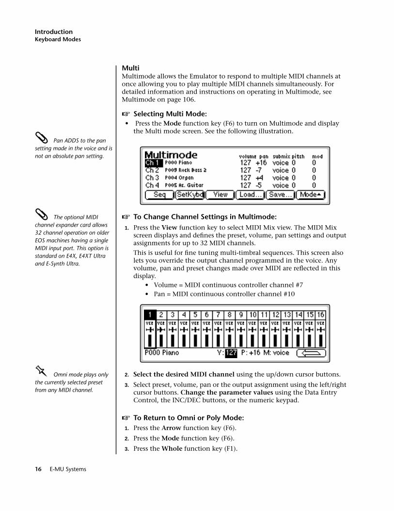
MultiMultimode allows the Emulator to respond to multiple MIDI channels at once allowing you to play multiple MIDI channels simultaneously. For detailed information and instructions on operating in Multimode, see Multimode on page 106.
v Selecting Multi Mode:• Press the Mode function key (F6) to turn on Multimode and display
the Multi mode screen. See the following illustration. Pan ADDS to the pan setting made in the voice and is not an absolute pan setting.
The optional MIDI channel expander card allows 32 channel operation on older EOS machines having a single MIDI input port. This option is standard on E4X, E4XT Ultra and E-Synth Ultra.
v To Change Channel Settings in Multimode:1. Press the View function key to select MIDI Mix view. The MIDI Mix
screen displays and defines the preset, volume, pan settings and output assignments for up to 32 MIDI channels.
This is useful for fine tuning multi-timbral sequences. This screen also lets you override the output channel programmed in the voice. Any volume, pan and preset changes made over MIDI are reflected in this display.
• Volume = MIDI continuous controller channel #7• Pan = MIDI continuous controller channel #10
OOOO Omni mode plays only the currently selected preset from any MIDI channel.
2. Select the desired MIDI channel using the up/down cursor buttons.
3. Select preset, volume, pan or the output assignment using the left/right cursor buttons. Change the parameter values using the Data Entry Control, the INC/DEC buttons, or the numeric keypad.
v To Return to Omni or Poly Mode:1. Press the Arrow function key (F6).
2. Press the Mode function key (F6).
3. Press the Whole function key (F1).
16 E-MU Systems

1The Basics

1 - The Basics
18 E-MU Systems
1 - The Basics
Definitions
How Sounds are OrganizedIt is important to understand how sounds are organized in order to make best use of the instrument in the shortest possible time. Many terms will be introduced now that show up later in the manual.
You can think of the Emulator as a collection of sound organizing modules, all contained within the currently loaded bank. Let’s take a closer look at what makes up this information, and how it is transferred from one section of the instrument to another. The Disk is the largest element in the hierarchy; the Sequence is the smallest element. The following gives a brief description of the EOS hierarchy.
Disk Drive. Floppy Disk, Hard Disks, CD-ROM Drives, Optical Drives, ROM Chips, etc.
Folder. Used to group and organize collections of Banks.
Bank. All samples, voices, and presets - Everything that resides in RAM (memory).
Preset. One complete keyboard setup containing one or more voices.
Voice. One complete sound which contains one or more samples with keyboard and velocity settings and all programmable synthesizer param-eters.
Sample. An individual digital recording with a name, sample rate and looping information.
Sequence. A sequence of key depressions, controller movements, program changes or system exclusive MIDI data. Up to 50 sequences can be stored with each bank, but sequences can also be exported as Standard MIDI Files or as Emulator sequences. They can even be saved to Flash RAM.
To explain the hierarchy, we’ll begin with individual elements, then work our way through the system.
EOS 4.0 Software Manual 19

1 - The BasicsThe Sample
The SampleLoading in any sound, in mono or stereo, creates a sample, the raw material with which the Emulator works.
The term sample commonly means two different things:
1. A digital recording of a complete sound, or
2. Each snapshot of the sound that makes up the complete sample.
In this manual, we’ll assume sample means the complete recorded sound unless indicated otherwise.
The total amount of available sampling time can be divided up any way you like—one long sample, lots of short samples, a few medium samples, or any combination thereof.
You can modify a raw sample in several ways. A sample can be transposed up or down in pitch to cover a particular range of the keyboard making it unnecessary to record a sample for every key. Sample editing might consist of Looping a sample (allowing even short samples to play indefinitely), Truncating (cutting off unneeded parts of a sample, thus saving memory), or any of a number of digital processes that actually change the raw sample data.
You can name samples also. It is usually a good idea to include the original pitch in the name so that you can place it on the keyboard later at the proper pitch. A bank can hold up to 1000 samples.
OriginalKey
LowKey
HighOrigLow HighOrigLow
HighKey
S02 Piano D3 S03 Piano D5S01 Piano A0
Sample Sample Sample
20 E-MU Systems
1 - The BasicsVoices
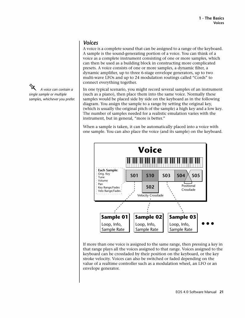
VoicesA voice is a complete sound that can be assigned to a range of the keyboard. A sample is the sound-generating portion of a voice. You can think of a voice as a complete instrument consisting of one or more samples, which can then be used as a building block in constructing more complicated presets. A voice consists of one or more samples, a dynamic filter, a dynamic amplifier, up to three 6-stage envelope generators, up to two multi-wave LFOs and up to 24 modulation routings called “Cords” to connect everything together.
OOOO A voice can contain a single sample or multiple samples, whichever you prefer.
In one typical scenario, you might record several samples of an instrument (such as a piano), then place them into the same voice. Normally these samples would be placed side by side on the keyboard as in the following diagram. You assign the sample to a range by setting the original key, (which is usually the original pitch of the sample) a high key and a low key. The number of samples needed for a realistic emulation varies with the instrument, but in general, “more is better.”
When a sample is taken, it can be automatically placed into a voice with one sample. You can also place the voice (and its sample) on the keyboard.
If more than one voice is assigned to the same range, then pressing a key in that range plays all the voices assigned to that range. Voices assigned to the keyboard can be crossfaded by their position on the keyboard, or the key stroke velocity. Voices can also be switched or faded depending on the value of a realtime controller such as a modulation wheel, an LFO or an envelope generator.
S01
Voice
S10
S02
S03 S05
PositionalCrossfade
Velocity Crossfade
S04Each Sample:Orig. KeyTuneVolumePanKey Range/FadesVelo Range/Fades
Sample 02Loop, Info,Sample Rate
Sample 03Loop, Info,Sample Rate
Sample 01Loop, Info,Sample Rate
EOS 4.0 Software Manual 21
1 - The BasicsThe Preset
The PresetA voice can be assigned to a single note on the keyboard, or transposed polyphonically to cover a wider keyboard range. A preset is one entire keyboard setup consisting of one or more voices. The process of assigning, and optionally transposing, samples to specific ranges of the keyboard is called making a preset. Making a preset is a three-step process:
1. Create the preset and give it a number and name.
2. Place voices in different keyboard ranges. For example, with six voices you could assign each voice to cover one octave of a six octave keyboard. A voice can be assigned more than once within a given preset, and assigned to more than one preset. Each preset can have up to 256 voices.
3. Choose from a number of available options that further define the preset. Some examples are: assigning samples to partially or fully overlap other samples, thus producing doubling effects, or assigning dynamic control to individual voices in a preset. Overlapping voices can be crossfaded using any modulation source. You can modify voice parameters and set up MIDI and dynamic processing parameters.
EOS allows you great flexibility in the way you construct presets. Consider this — you can assign multiple samples to the keyboard inside the voice or assign single sample voices to the keyboard. Unless you specify otherwise, only one sample is assigned per voice. In this case you would assign voices (and the single sample each one contains) to the keyboard and create presets. On the other hand, you may want to create finished voices before you start designing presets and treat the voice as your finished sound. In this case, the preset can be used to crossfade, layer or switch multiple complex voices.
22 E-MU Systems
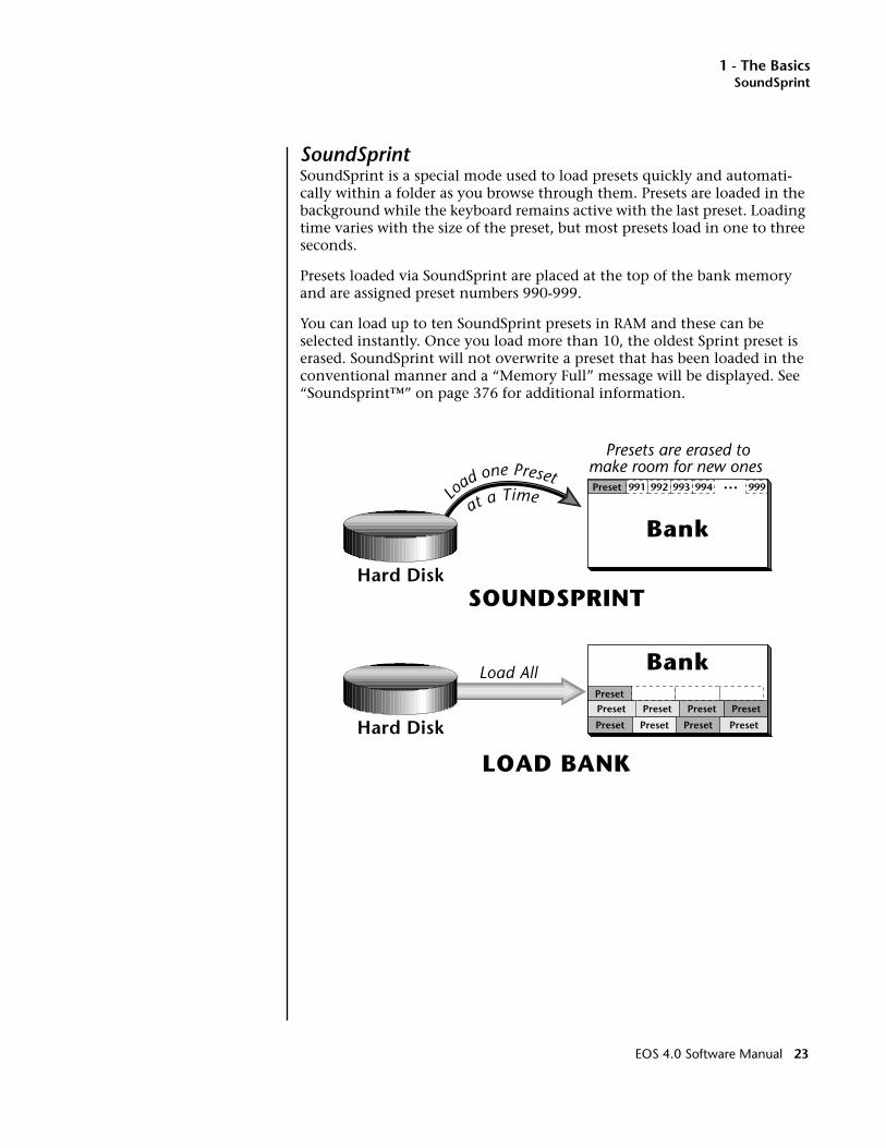
1 - The BasicsSoundSprint
SoundSprintSoundSprint is a special mode used to load presets quickly and automati-cally within a folder as you browse through them. Presets are loaded in the background while the keyboard remains active with the last preset. Loading time varies with the size of the preset, but most presets load in one to three seconds.
Presets loaded via SoundSprint are placed at the top of the bank memory and are assigned preset numbers 990-999.
You can load up to ten SoundSprint presets in RAM and these can be selected instantly. Once you load more than 10, the oldest Sprint preset is erased. SoundSprint will not overwrite a preset that has been loaded in the conventional manner and a “Memory Full” message will be displayed. See “Soundsprint™” on page 376 for additional information.
Preset Diagram
Bank
Bank
SOUNDSPRINT
LOAD BANK
PresetPreset
PresetPreset
Preset
Load All
Preset
Preset
Preset
Preset
Preset 991 992 993 994 999Load one Preset
at a Time
Hard Disk
Hard Disk
Presets are erased tomake room for new ones
EOS 4.0 Software Manual 23
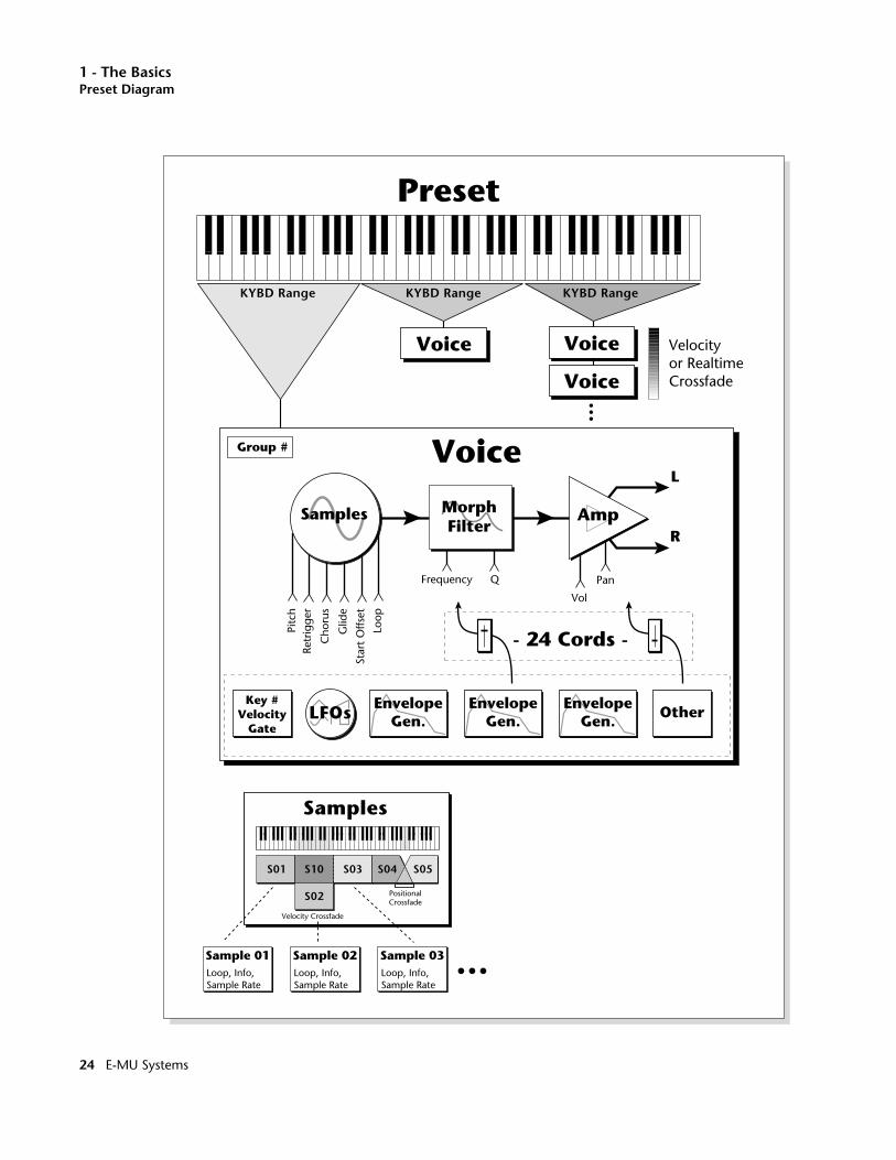
1 - The BasicsPreset Diagram
Samples Amp
L
R
LFOs EnvelopeGen.
EnvelopeGen.
EnvelopeGen.
OtherKey #
VelocityGate
Retr
igge
rPi
tch
Loop
Frequency Q
Vol
Pan
Cho
rus
Glid
e
Star
t O
ffset
Voice
Preset
- 24 Cords -
Voice
Voice
Voice
KYBD Range KYBD Range KYBD Range
Sample 02Loop, Info,Sample Rate
Sample 03Loop, Info,Sample Rate
Sample 01Loop, Info,Sample Rate
S01
Samples
S10
S02
S03 S05
PositionalCrossfade
Velocity Crossfade
S04
Velocityor RealtimeCrossfade
Group #
MorphFilter
24 E-MU Systems
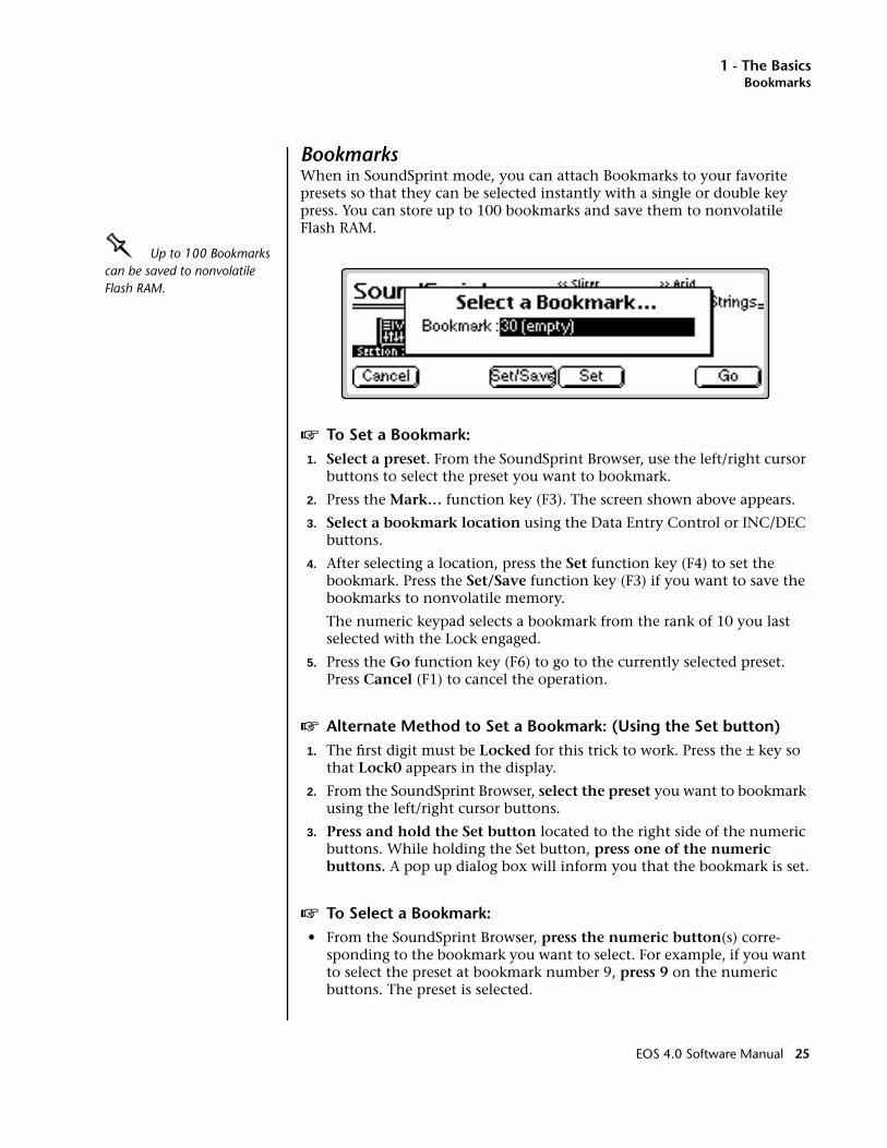
1 - The BasicsBookmarks
BookmarksWhen in SoundSprint mode, you can attach Bookmarks to your favorite presets so that they can be selected instantly with a single or double key press. You can store up to 100 bookmarks and save them to nonvolatile Flash RAM.
OOOO Up to 100 Bookmarks can be saved to nonvolatile Flash RAM.
v To Set a Bookmark:1. Select a preset. From the SoundSprint Browser, use the left/right cursor
buttons to select the preset you want to bookmark.
2. Press the Mark… function key (F3). The screen shown above appears.
3. Select a bookmark location using the Data Entry Control or INC/DEC buttons.
4. After selecting a location, press the Set function key (F4) to set the bookmark. Press the Set/Save function key (F3) if you want to save the bookmarks to nonvolatile memory.
The numeric keypad selects a bookmark from the rank of 10 you last selected with the Lock engaged.
5. Press the Go function key (F6) to go to the currently selected preset. Press Cancel (F1) to cancel the operation.
v Alternate Method to Set a Bookmark: (Using the Set button)1. The first digit must be Locked for this trick to work. Press the ± key so
that Lock0 appears in the display.
2. From the SoundSprint Browser, select the preset you want to bookmark using the left/right cursor buttons.
3. Press and hold the Set button located to the right side of the numeric buttons. While holding the Set button, press one of the numeric buttons. A pop up dialog box will inform you that the bookmark is set.
v To Select a Bookmark:• From the SoundSprint Browser, press the numeric button(s) corre-
sponding to the bookmark you want to select. For example, if you want to select the preset at bookmark number 9, press 9 on the numeric buttons. The preset is selected.
EOS 4.0 Software Manual 25
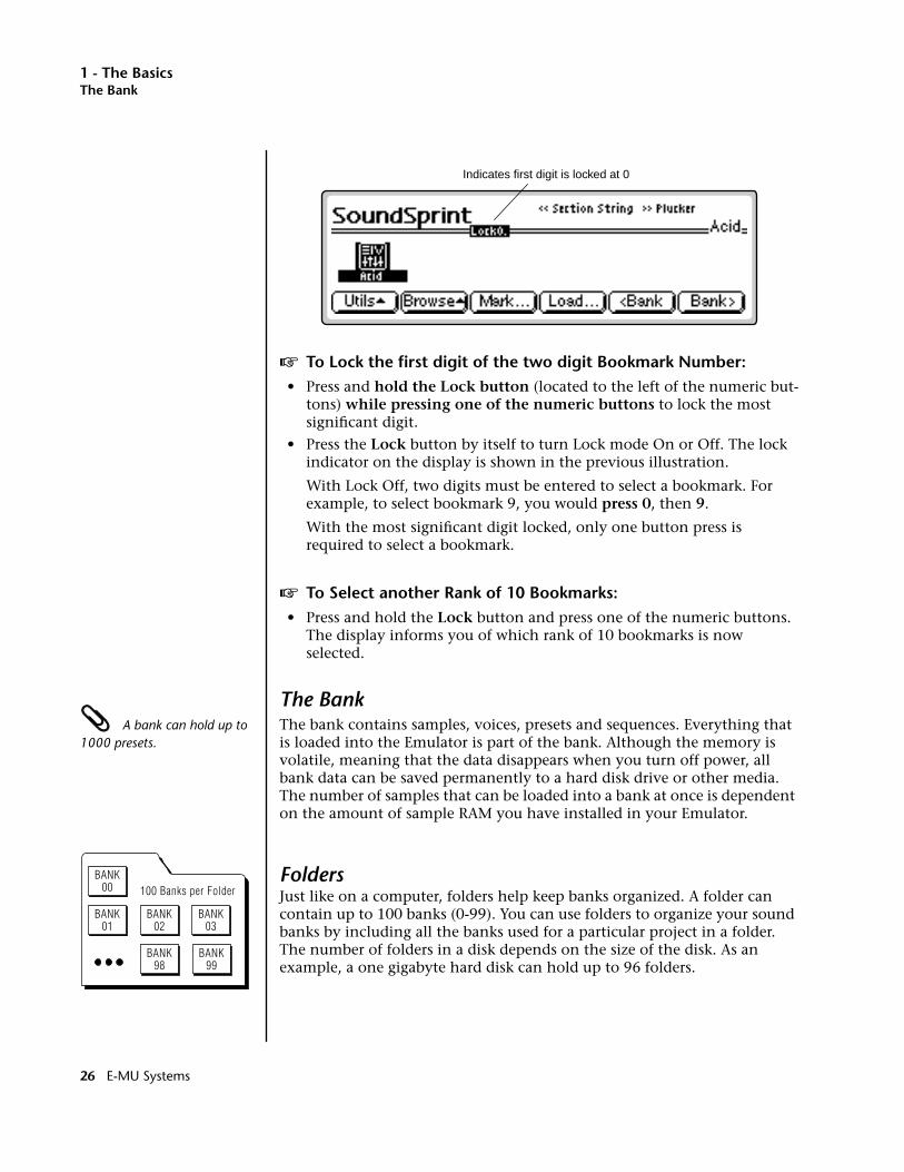
1 - The BasicsThe Bank
v To Lock the first digit of the two digit Bookmark Number:• Press and hold the Lock button (located to the left of the numeric but-
tons) while pressing one of the numeric buttons to lock the most significant digit.
• Press the Lock button by itself to turn Lock mode On or Off. The lock indicator on the display is shown in the previous illustration.
With Lock Off, two digits must be entered to select a bookmark. For example, to select bookmark 9, you would press 0, then 9.
With the most significant digit locked, only one button press is required to select a bookmark.
v To Select another Rank of 10 Bookmarks: • Press and hold the Lock button and press one of the numeric buttons.
The display informs you of which rank of 10 bookmarks is now selected.
The Bank A bank can hold up to 1000 presets.
The bank contains samples, voices, presets and sequences. Everything that is loaded into the Emulator is part of the bank. Although the memory is volatile, meaning that the data disappears when you turn off power, all bank data can be saved permanently to a hard disk drive or other media. The number of samples that can be loaded into a bank at once is dependent on the amount of sample RAM you have installed in your Emulator.
FoldersJust like on a computer, folders help keep banks organized. A folder can contain up to 100 banks (0-99). You can use folders to organize your sound banks by including all the banks used for a particular project in a folder. The number of folders in a disk depends on the size of the disk. As an example, a one gigabyte hard disk can hold up to 96 folders.
Indicates first digit is locked at 0
BANK00
BANK01
BANK98
BANK02
BANK99
BANK03
100 Banks per Folder
26 E-MU Systems
1 - The BasicsThe Internal Drive
The Internal DriveA disk drive is a memory storage device that stores banks of data. The floppy drive is used mainly to update the operating system software. (The operating system consists of the instructions that tell the Emulator what to do.) Other types of disk drives, as described below, can connect to the Emulator to provide efficient sound storage.
Floppy Disk Drive: The floppy disk drive requires 3.5", double-sided, high-density (1.4 MB) floppy disks. As new enhancements are developed, the new software is distributed on floppy disks. The floppy drive is used to update the operating system software. This software can be copied into Flash RAM and made a permanent part of the Emulator itself.
It is also ideal for transferring sequences to and from a computer-based sequencer. With large bank sizes of 4-128 MB, the floppy disk becomes impractical for backing up sound data, although it can be used to save or transfer small sound banks in a pinch.
EOS accepts 2 kinds of floppy formats. DOS formatted disks allow multiple files per disk and are compatible with PC and Macintosh computers. EOS formatted disks allow one bank to be spread over multiple disks.
Note: The Emulator can format floppies in EOS format only. DOS floppies must be formatted on a PC or Mac computer or purchased preformatted. EOS cannot read Macintosh floppies, but fortunately the Mac can read and format DOS floppy disks.
To Update the EOS Software:Since the EOS operating system is stored in Flash ROM, it can be easily updated to add features or to fix bugs. The following procedure explains how.
Check the E-mu web site at: www.emu.com for the latest software updates & downloads.
1. Turn off power.
2. Insert the floppy disk into the drive.
3. Turn on power.
4. Press Enter to update or Exit to cancel.
5. Wait for the Emulator to update its firmware.
6. Re-initialize EEPROM. (This should be done after a software update to “clean the slate”. It resets the Master menu preferences and other bits.)
a. Press Master
b. Press Utils
c. Press Tests
d. Enter the Secret Password: 1-3-5-8, then press OK.
e. Press More
f. Press InitEE The display reads, “Initialize EE?”
g. Press OK. The display reads, “Saving System”
f. Press Master to exit diagnostics mode.
7. Recalibrate the Emulator controls. See “Recalibration” on page 68.
EOS 4.0 Software Manual 27

1 - The BasicsExternal Drives
Internal Hard Disk Drive: A hard disk provides the advantages of much higher memory capacity and far faster access time than floppy disks. However, the hard disk cannot be removed and its data must be backed up to another medium for safekeeping.
IDE Drives: The Ultra series Emulators can make use of an internal IDE hard disk. An IDE drive has several advantages including: low cost, high capacity, low noise and it doesn’t use up a precious SCSI ID number. Order IDE installation kit #6303. This includes everything needed except the IDE drive.
External DrivesEmulators are equipped with SCSI (Small Computer Systems Interface) connector(s) on the rear panel. This interface is commonly used in the computer industry, so many devices made to work with computers—partic-ularly mass storage devices—will also work with Emulators. Here are some of the types of mass storage devices that can be connected to the Emulator using the SCSI connectors.
OOOO Use the “Mount Drives” utility whenever an external SCSI device does not appear in the display.
Hard Disk Drive: A hard disk provides the advantages of high memory capacity and fast access time. Transferring data is quite straightforward. However, you cannot remove a hard disk and replace it with another one—the disk is a permanent part of the drive. There are some important cautions involved with hard disks:
1. Hard disks are sensitive to extreme mechanical shocks. If your hard disk falls off a keyboard stand, chances are the hard disk will be damaged.
2. Hard disks have reached a very high level of reliability. However, they can fail from time to time (as can any part of a computer), so any data should be backed up periodically on some other medium.
Removable-media Hard Disk Drives: These are similar to standard hard disk drives except that the disk itself can be removed and replaced with another disk (similar to floppy disks). Disk densities can range from 44MB to well over 1 Gigabyte (GB) per platter. Removable-media hard disk drives make it easy for you to build a sound library of unlimited size and are quite handy for transferring sounds between machines. They’re also perfect for backups because you can remove the media and keep it in a safe place.
CD-ROM Drive: A CD-ROM is a playback-only mass storage memory device whose capacity is approximately 660MB. Quality CD-ROM libraries are available from several companies (E-mu Systems, InVision, Northstar, Q-Up Arts and many others). These can be loaded into the bank just like a hard disk.
Magneto-Optical Drive: These high speed, high density storage devices are ideal for storing large amounts of sound data. Typically a magneto-optical drive can hold upwards of 300 MB per side and the removable cartridges can be used over and over. Disk access time is comparable to a normal hard disk. Although you can read and write to these drives, they are generally slower than most hard disks.
28 E-MU Systems
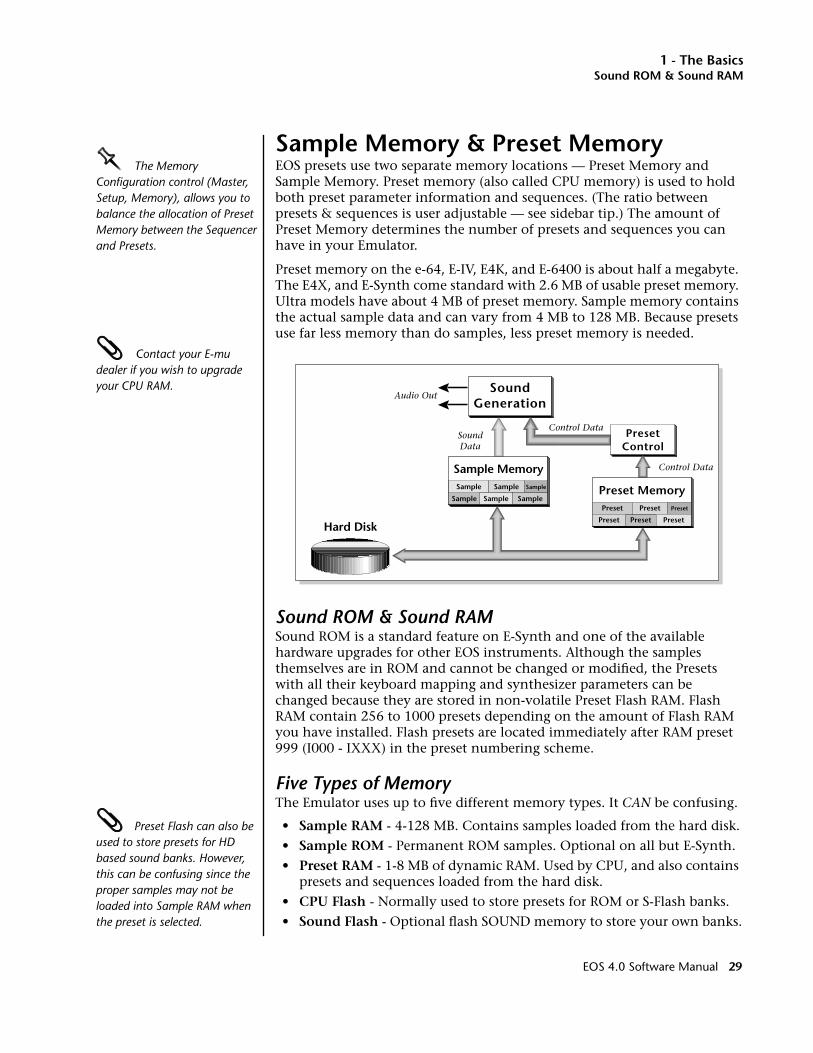
1 - The BasicsSound ROM & Sound RAM
Sample Memory & Preset MemoryOOOO The Memory Configuration control (Master, Setup, Memory), allows you to balance the allocation of Preset Memory between the Sequencer and Presets.
EOS presets use two separate memory locations — Preset Memory and Sample Memory. Preset memory (also called CPU memory) is used to hold both preset parameter information and sequences. (The ratio between presets & sequences is user adjustable — see sidebar tip.) The amount of Preset Memory determines the number of presets and sequences you can have in your Emulator.
Preset memory on the e-64, E-IV, E4K, and E-6400 is about half a megabyte. The E4X, and E-Synth come standard with 2.6 MB of usable preset memory. Ultra models have about 4 MB of preset memory. Sample memory contains the actual sample data and can vary from 4 MB to 128 MB. Because presets use far less memory than do samples, less preset memory is needed.
Contact your E-mu dealer if you wish to upgrade your CPU RAM.
Sound ROM & Sound RAMSound ROM is a standard feature on E-Synth and one of the available hardware upgrades for other EOS instruments. Although the samples themselves are in ROM and cannot be changed or modified, the Presets with all their keyboard mapping and synthesizer parameters can be changed because they are stored in non-volatile Preset Flash RAM. Flash RAM contain 256 to 1000 presets depending on the amount of Flash RAM you have installed. Flash presets are located immediately after RAM preset 999 (I000 - IXXX) in the preset numbering scheme.
Five Types of MemoryThe Emulator uses up to five different memory types. It CAN be confusing.
Preset Flash can also be used to store presets for HD based sound banks. However, this can be confusing since the proper samples may not be loaded into Sample RAM when the preset is selected.
• Sample RAM - 4-128 MB. Contains samples loaded from the hard disk.
• Sample ROM - Permanent ROM samples. Optional on all but E-Synth.
• Preset RAM - 1-8 MB of dynamic RAM. Used by CPU, and also contains presets and sequences loaded from the hard disk.
• CPU Flash - Normally used to store presets for ROM or S-Flash banks.
• Sound Flash - Optional flash SOUND memory to store your own banks.
SoundGeneration
Audio Out
SoundData
Control Data
Control DataSample Memory
Hard Disk
Sample
Sample Sample
Sample
Sample
Sample Preset MemoryPreset
PresetPreset
Preset
Preset
Preset
PresetControl
EOS 4.0 Software Manual 29
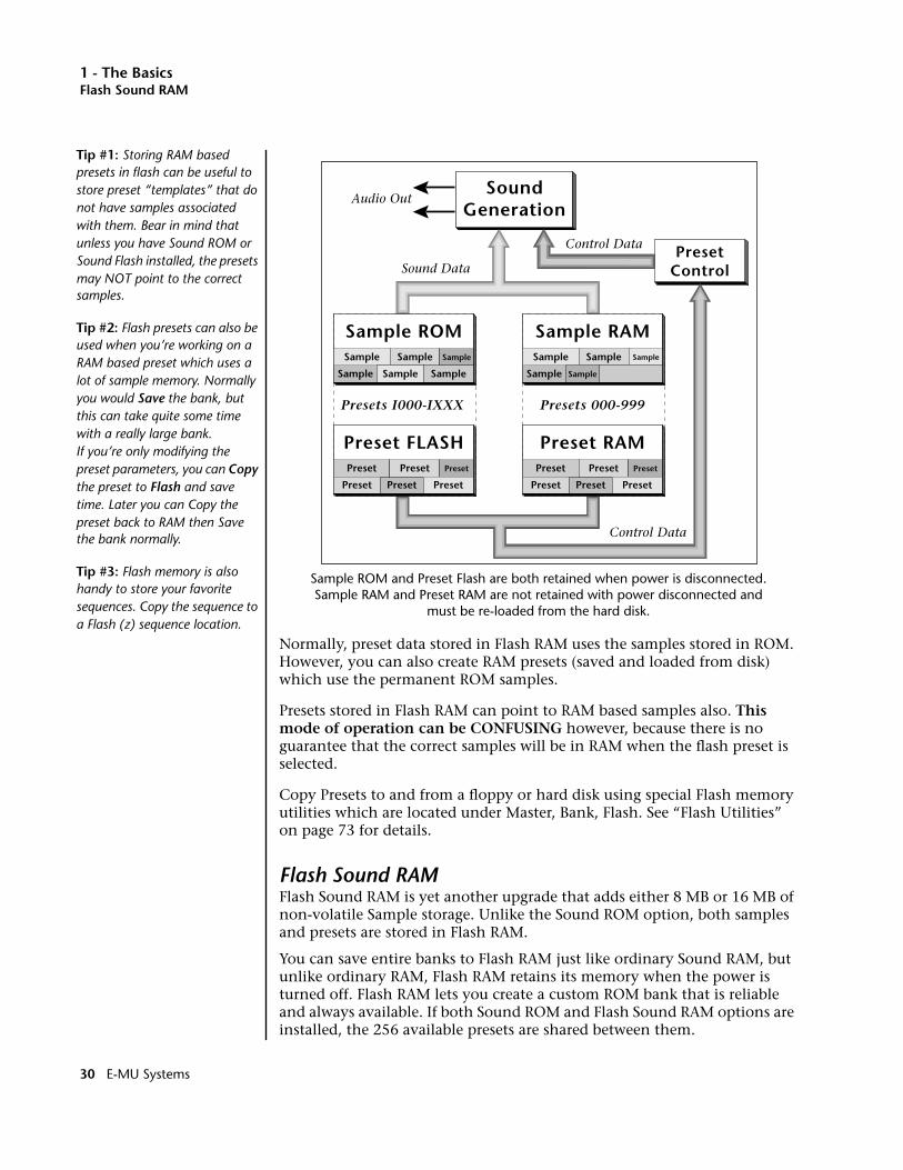
1 - The BasicsFlash Sound RAM
Sample ROM and Preset Flash are both retained when power is disconnected. Sample RAM and Preset RAM are not retained with power disconnected and
must be re-loaded from the hard disk.
Normally, preset data stored in Flash RAM uses the samples stored in ROM. However, you can also create RAM presets (saved and loaded from disk) which use the permanent ROM samples.
Presets stored in Flash RAM can point to RAM based samples also. This mode of operation can be CONFUSING however, because there is no guarantee that the correct samples will be in RAM when the flash preset is selected.
Copy Presets to and from a floppy or hard disk using special Flash memory utilities which are located under Master, Bank, Flash. See “Flash Utilities” on page 73 for details.
Flash Sound RAMFlash Sound RAM is yet another upgrade that adds either 8 MB or 16 MB of non-volatile Sample storage. Unlike the Sound ROM option, both samples and presets are stored in Flash RAM.
You can save entire banks to Flash RAM just like ordinary Sound RAM, but unlike ordinary RAM, Flash RAM retains its memory when the power is turned off. Flash RAM lets you create a custom ROM bank that is reliable and always available. If both Sound ROM and Flash Sound RAM options are installed, the 256 available presets are shared between them.
PresetControl
SoundGeneration
Sample RAMSample
Sample
SampleSample
SampleSample
Sample ROMSample
Sample Sample
Sample
Sample
Sample
Preset FLASHPreset
PresetPreset
Preset
Preset
Preset
Preset RAMPreset
PresetPreset
Preset
Preset
Preset
Presets 000-999Presets I000-IXXX
Audio Out
Sound Data
Control Data
Control Data
Tip #1: Storing RAM based presets in flash can be useful to store preset “templates” that do not have samples associated with them. Bear in mind that unless you have Sound ROM or Sound Flash installed, the presets may NOT point to the correct samples.
Tip #2: Flash presets can also be used when you’re working on a RAM based preset which uses a lot of sample memory. Normally you would Save the bank, but this can take quite some time with a really large bank. If you’re only modifying the preset parameters, you can Copy the preset to Flash and save time. Later you can Copy the preset back to RAM then Save the bank normally.
Tip #3: Flash memory is also handy to store your favorite sequences. Copy the sequence to a Flash (z) sequence location.
30 E-MU Systems

1 - The BasicsSample Numbers
Sample NumbersThe Emulator contains two internal SIMM sockets for use by Sound ROM and Flash Sound RAM. These special sockets are designated X and Y. If you have either Sound ROM or Sound Flash RAM installed, you'll notice that the samples stored in these locations have the prefix X or Y before the sample number. (Press Preset Edit to see the sample assignments) Similarly samples stored in main sample RAM use the designator “S” before the sample number, as in “S003”.
Using Preset Flash MemoryThe Preset Flash memory comes pre-loaded with 256 Presets. If you need to reload the factory presets, use the following instructions.
v To Upload the Factory Presets into Flash:1. Power up the machine and wait for it to finish booting.
2. Press the Master button.
3. Press the Setup function key (F3).
4. Press the Memory function key (F6).
5. Set the Memory Configuration. To load the 8 MB FLASH Presets you’ll need at least 85K of Preset Memory. To load the “Big RAM” Presets you’ll need at least 507K of Preset Memory.
6. Press the Save function key (F6).
7. Press the Master button again to exit the Master module.
8. Insert the floppy disk containing the factory presets into the drive with the label side towards the center of the unit.
9. Press the Load function key (F4). The pop-up Load window appears.
10. Set the Drive to “Floppy” using the cursor buttons and Data Entry Control.
SoundGeneration
FLASH RAM
Presets I000 -
SAMPLE RAM
Presets 000 - 999
8 or 16 MB4-128 MB
Audio Out
I 255I 999
Flash Sound RAM
dependingon installedFlash RAM
EOS 4.0 Software Manual 31

1 - The BasicsUsing Sound Flash Memory
11. Press the Load function key (F6).
12. When the bank has finished loading, press the Master button.
13. Press the Bank function key (F2).
14. Press the Flash function key (F6).
15. Press the RAM➔F function key (F3). A warning screen appears advising you that you are about to overwrite Flash RAM.
16. Press OK (F6) to write the bank to Flash RAM.
Using Sound Flash MemorySound Flash Memory is a similar to a hard disk containing one bank. A bank is assembled in Sample RAM, then Saved to Flash Memory. Individual presets can be saved to Flash Memory using the Copy function in the Preset Manage module.
v To Save a Bank to Flash Memory:1. Erase the Bank
• Press the Master button.
• Press the Bank function key (F2).
• Press the Erase function key (F1).
2. Load the Bank you want to Save to Flash
• From the main screen, press Load.
• Select the Drive, Folder and Bank you want to Save to Flash, then press Load. The bank will load into RAM.
3. Save the Sounds to Flash.
• Press Save.
• Select Flash Memory as the drive you wish to Save to, then press OK (F6). The Samples will be stored in Flash Sound RAM.
4. Mount the Drive.
• Press Disk.
• Press Utils (F1).
• Press Mount (F1).
5. Erase the Bank…again
• Press Master.
• Press Bank (F2).
• Press Erase (F1).
32 E-MU Systems
1 - The BasicsUsing Sound Flash Memory
6. Erase Preset 000This operation deletes the empty preset in the P000 location of the bank so it won’t get merged into your Flash Bank. Unfortunately, you must have at least one preset in the bank, so before deleting P000 we’ll create a new empty preset at location 999.
• Press Preset Manage.
• Press New…
• Select destination preset P999 Empty Preset.
• Press OK, twice.
• Select P000 Untitled Preset.
• Press Utils (F1).
• Press Erase Preset (F1). Press OK (F6).
7. Merge the Presets. Merging the presets into the bank will point to the correct locations in the Flash Sound Memory bank. The Emulator sees that the samples are in Flash Sound Memory and changes the sample numbers so they point to Flash.
• From the main screen, press the Arrow button, then Load.
• Select the Drive, Folder and Bank you want to Save to Flash, then press Merge.
8. Save the Presets. Now that the sample numbers point to the samples in Flash Sound Memory, write the presets into CPU Flash memory using the Flash utilities.
• Press Master.
• Press Bank (F2).
• Press Flash (F6).
• Press RAM->F (F3). A warning screen appears.
• Press OK (F6). The presets are written into CPU Flash memory.
v To Copy Flash RAM Presets to Disk:1. Power up the machine and wait for it to finish booting.
2. Press the Master button.
3. Press the Bank function key (F2).
4. Press the Flash function key (F6).
5. Press the F➔RAM function key (F4). A warning screen appears advising you that you are about to overwrite RAM.
6. Press OK (F6) to write to RAM.
7. Press the Master button to return to the main screen.
8. Insert the floppy disk into the drive if you wish to copy to floppy disk.
9. Press the Save function key (F5). The pop-up Save window appears.
EOS 4.0 Software Manual 33
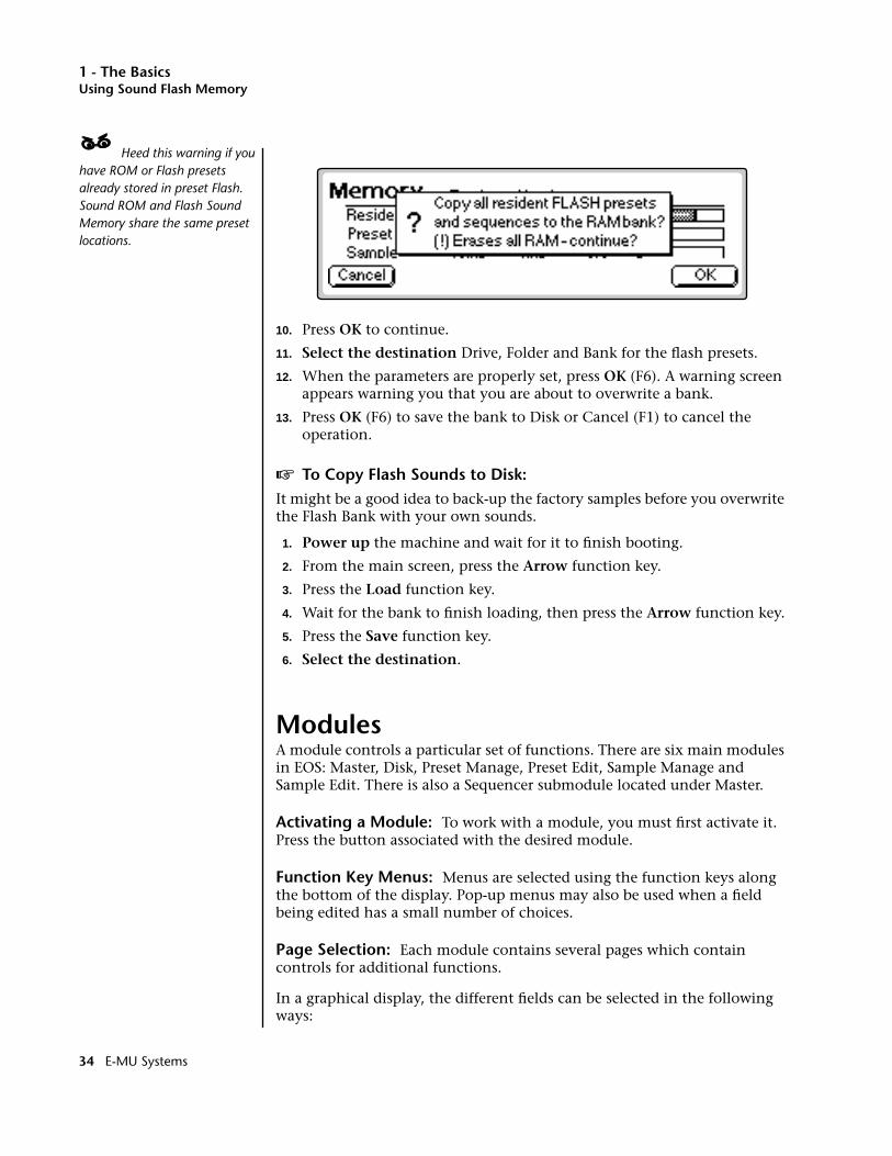
1 - The BasicsUsing Sound Flash Memory
____ Heed this warning if you have ROM or Flash presets already stored in preset Flash. Sound ROM and Flash Sound Memory share the same preset locations.
10. Press OK to continue.
11. Select the destination Drive, Folder and Bank for the flash presets.
12. When the parameters are properly set, press OK (F6). A warning screen appears warning you that you are about to overwrite a bank.
13. Press OK (F6) to save the bank to Disk or Cancel (F1) to cancel the operation.
v To Copy Flash Sounds to Disk:It might be a good idea to back-up the factory samples before you overwrite the Flash Bank with your own sounds.
1. Power up the machine and wait for it to finish booting.
2. From the main screen, press the Arrow function key.
3. Press the Load function key.
4. Wait for the bank to finish loading, then press the Arrow function key.
5. Press the Save function key.
6. Select the destination.
ModulesA module controls a particular set of functions. There are six main modules in EOS: Master, Disk, Preset Manage, Preset Edit, Sample Manage and Sample Edit. There is also a Sequencer submodule located under Master.
Activating a Module: To work with a module, you must first activate it. Press the button associated with the desired module.
Function Key Menus: Menus are selected using the function keys along the bottom of the display. Pop-up menus may also be used when a field being edited has a small number of choices.
Page Selection: Each module contains several pages which contain controls for additional functions.
In a graphical display, the different fields can be selected in the following ways:
34 E-MU Systems

1 - The BasicsUsing Sound Flash Memory
• By pressing the cursor buttons (up, down, left, right).
• By turning the Data Entry Control.
• By assigning an assignable key to jump directly to the screen you want to edit.
Pressing the module button or the Exit button cancels any operation.
The Module buttons are located on the left side of the control panel. Each module affects a specific area of the Emulator's operation.
Disk: This module controls everything to do with the disk drives where sounds are stored. You can browse through the disks, examine their contents and audition sounds directly from a hard disk before loading. If you are looking for a specific sound, you can use the “Find” function to quickly locate it. See “Disk Menu” on page 357.
Master: This module contains functions that affect the entire machine, such as master tuning, headroom, master FX, output sample rate, LCD contrast, and much more. “Master Utilities” on page 65.
Sample Manage: This “recording studio” module records sounds from the outside world into the bank. Features include adjustable preamp gain, variable threshold setting, and adjustable sample rate and length. “Sample Utilities” on page 174.
Sample Edit: With this powerful module, you can edit a sample's length, loop (i.e. infinitely sustain) any portion of the sample and automatically find the best loop points using Auto Correlate. You can splice two different samples together, mix samples, or perform a variety of advanced digital signal processes on the sample. “Sample Edit” on page 193.
Preset Manage: This module handles the preset “housekeeping”, allowing you to create new presets, copy them to any location, rename them or erase them. “Preset Manage” on page 245.
Preset Edit: This module lets you alter the synthesizer voice parameters, such as shaping the amplitude and filter dynamics or adjusting the keyboard dynamic response. Voices can be placed on the keyboard, moved around or shaped in just about any possible way. “Editing Presets” on page 253.
Sequencer: This module accesses the 48-track sequencer which is located inside the Master module. The Sequencer can be quickly accessed by holding the Set/Shift button (decimal point) and pressing Assignable Key 1. “Sequence Manage” on page 133.
Effects: This module controls the realtime FX processors. It is located in the Master and also the Preset modules, but can be quickly accessed by
EOS 4.0 Software Manual 35
1 - The BasicsSaving
holding the Set/Shift button (decimal point) and pressing Assignable Key 2. “Effects” on page 117.
SoundSprint: This function automatically loads presets as you browse through them. SoundSprint can be quickly accessed by holding the Set/Shift button (decimal point) and pressing Assignable Key 3. “SoundSprint” on page 23.
More Definitions
SavingThe RAM bank retains data only for as long as the Emulator is plugged in and turned on. Of course, we don’t expect you to leave the thing on all the time, which brings us to the subject of saving data.
Pressing the SAVE function key from the Disk module or Main Screen shuttles all the bank data (samples, voices, presets and sequences) to the drive of your choice. A hard disk permanently stores data so that even after turning off the Emulator, the disk stores a record of your work.
IF YOU DO NOT SAVE A BANK, ALL BANK DATA WILL BE LOST WHEN YOU TURN OFF THE MACHINE!
Do not wait until the end of a session to save. Save your work periodically in case of power failure or some other unforeseen circumstance that might erase the bank’s memory. Hard disks are not infallible. All hard disk banks should be backed up periodically to another hard disk or other media. Should you improve the preset or sample later, you can always replace the original with the revised version. And if something goes wrong, the original will still be available to save you the ordeal of starting from scratch.
Whenever you have done enough work that you would hate to lose it, BACK IT UP!
DefaultA default setting is what we’ve judged to be a useful initial setting, and remains in effect until you change it. For example, if you create a new preset, the transpose setting defaults to “0.” Had the default value been “+12,” all new presets would be transposed up an octave until you change the value.
IconsAn icon is a little picture of an object such as a floppy disk, a hard disk, folders, banks, presets or samples. In the disk browser screens, icons are used as an easy way to identify and select the appropriate object. When an icon is selected, the image will reverse (black to white & vice-versa).This is the icon for
the floppy disk drive
36 E-MU Systems
1 - The BasicsThe Cursor
The CursorThe cursor is a highlighted area on the display. It shows you the number or letter that will be altered if you enter data. Entering a new value overwrites the number or letter above the cursor, whereupon the cursor moves on to the next number or letter (if applicable). If the Emulator is expecting a two or three-digit number, in most cases you must enter all the required digits even if some of these are zeroes (called leading zeroes). For example, if the Emulator is expecting a three-digit number and you want to enter 8, you would enter 008. If it is expecting a single-digit number, entering 8 would be sufficient.
Data Entry Control & Increment/Decrement ButtonsIn virtually all instances where the Data Entry Control selects options, the increment (Inc/Yes) and decrement (Dec/No) buttons duplicate the Data Entry Control. Press Inc/Yes to increase a value, or Dec/No to decrease by one value at a time.
SelectingWhen the instructions say to select an option, you can use whatever method is most comfortable for you: the Data Entry Control, the increment/decrement buttons, the numeric keypad (if applicable) and, when naming, the keyboard keys. Some functions do not implement all these options. (You can’t go wrong by trying, though. If a function doesn’t respond to the numeric keypad, for instance, then pressing the keypad will have no effect.) Use the Data Entry Control or the INC/DEC buttons instead.
The Big Re-Cap• A sample is a raw sound that is loaded into the bank.
• A voice is a complete sound, consisting of one or more samples, processed through the dynamic signal processors, that is mapped onto the keyboard.
• To create a new preset, make sure you have all the samples required for the preset, then assign combinations of voices from the bank to specific sections of the keyboard.
• After arranging a bank, it can be saved to one or more drives or to Flash Memory.
• Since loading from a hard disk fills the bank with samples, voices and presets, you can group these voices and samples into new presets, pro-cess the samples contained in particular voices, or alter existing presets.
• Presets loaded via SoundSprint are always placed in preset locations 990-999.
• Up to 50 sequences can be saved with the bank. An additional 50 sequences can be saved into Flash (if you have it). Flash sequences are designated by a “z” in front of the sequence number. Exported or Standard MIDI File sequences appear in the Bank browser.
EOS 4.0 Software Manual 37
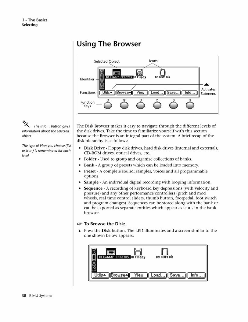
1 - The BasicsSelecting
Using The Browser
OOOO The Info… button gives information about the selected object.
The type of View you choose (list or icon) is remembered for each level.
The Disk Browser makes it easy to navigate through the different levels of the disk drives. Take the time to familiarize yourself with this section because the Browser is an integral part of the system. A brief recap of the disk hierarchy is as follows:
• Disk Drive - Floppy disk drives, hard disk drives (internal and external), CD-ROM drives, optical drives, etc.
• Folder - Used to group and organize collections of banks.
• Bank - A group of presets which can be loaded into memory.
• Preset - A complete sound: samples, voices and all programmable options.
• Sample - An individual digital recording with looping information.
• Sequence - A recording of keyboard key depressions (with velocity and pressure) and any other performance controllers (pitch and mod wheels, real time control sliders, thumb button, footpedal, foot switch and program changes). Sequences can be stored along with the bank or can be exported as separate entities which appear as icons in the bank browser.
v To Browse the Disk:1. Press the Disk button. The LED illuminates and a screen similar to the
one shown below appears.
ActivatesSubmenu
Function Keys
Functions
Identifier
Selected Object Icons
38 E-MU Systems
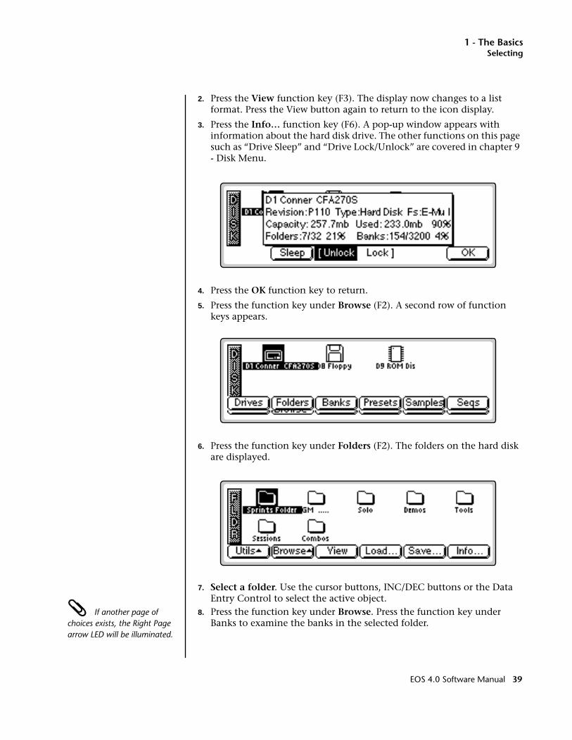
1 - The BasicsSelecting
2. Press the View function key (F3). The display now changes to a list format. Press the View button again to return to the icon display.
3. Press the Info… function key (F6). A pop-up window appears with information about the hard disk drive. The other functions on this page such as “Drive Sleep” and “Drive Lock/Unlock” are covered in chapter 9 - Disk Menu.
4. Press the OK function key to return.
5. Press the function key under Browse (F2). A second row of function keys appears.
6. Press the function key under Folders (F2). The folders on the hard disk are displayed.
7. Select a folder. Use the cursor buttons, INC/DEC buttons or the Data Entry Control to select the active object.
If another page of choices exists, the Right Page arrow LED will be illuminated.
8. Press the function key under Browse. Press the function key under Banks to examine the banks in the selected folder.
EOS 4.0 Software Manual 39
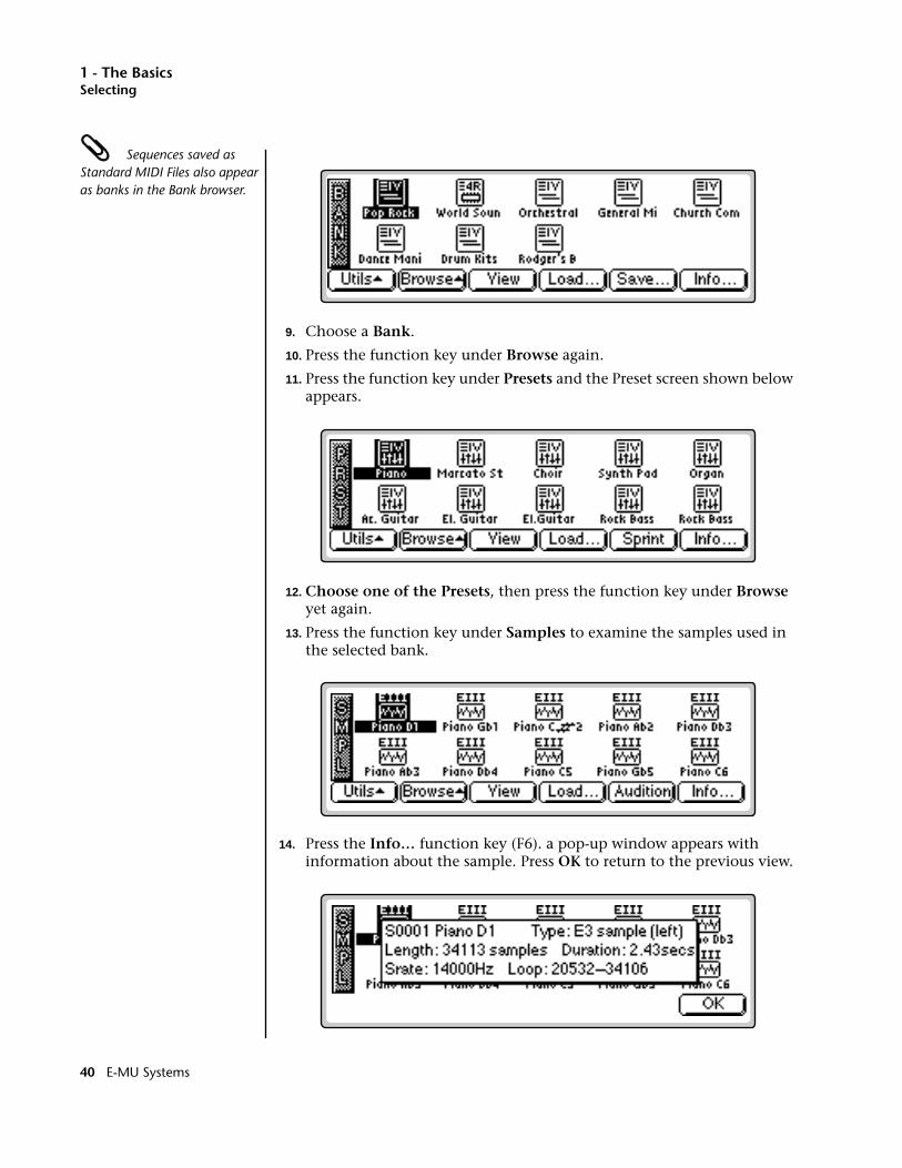
1 - The BasicsSelecting
Sequences saved as Standard MIDI Files also appear as banks in the Bank browser.
9. Choose a Bank.
10. Press the function key under Browse again.
11. Press the function key under Presets and the Preset screen shown below appears.
12. Choose one of the Presets, then press the function key under Browse yet again.
13. Press the function key under Samples to examine the samples used in the selected bank.
14. Press the Info… function key (F6). a pop-up window appears with information about the sample. Press OK to return to the previous view.
40 E-MU Systems
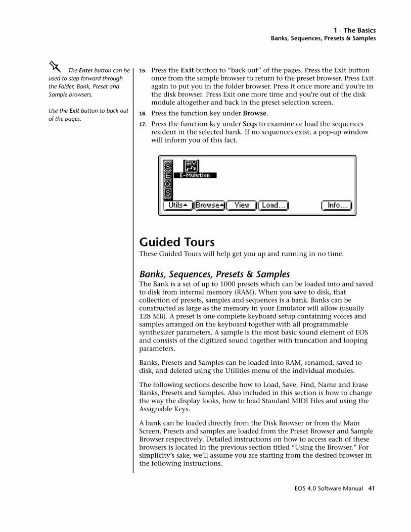
1 - The BasicsBanks, Sequences, Presets & Samples
OOOO The Enter button can be used to step forward through the Folder, Bank, Preset and Sample browsers.
Use the Exit button to back out of the pages.
15. Press the Exit button to “back out” of the pages. Press the Exit button once from the sample browser to return to the preset browser. Press Exit again to put you in the folder browser. Press it once more and you're in the disk browser. Press Exit one more time and you're out of the disk module altogether and back in the preset selection screen.
16. Press the function key under Browse.
17. Press the function key under Seqs to examine or load the sequences resident in the selected bank. If no sequences exist, a pop-up window will inform you of this fact.
Guided ToursThese Guided Tours will help get you up and running in no time.
Banks, Sequences, Presets & SamplesThe Bank is a set of up to 1000 presets which can be loaded into and saved to disk from internal memory (RAM). When you save to disk, that collection of presets, samples and sequences is a bank. Banks can be constructed as large as the memory in your Emulator will allow (usually 128 MB). A preset is one complete keyboard setup containing voices and samples arranged on the keyboard together with all programmable synthesizer parameters. A sample is the most basic sound element of EOS and consists of the digitized sound together with truncation and looping parameters.
Banks, Presets and Samples can be loaded into RAM, renamed, saved to disk, and deleted using the Utilities menu of the individual modules.
The following sections describe how to Load, Save, Find, Name and Erase Banks, Presets and Samples. Also included in this section is how to change the way the display looks, how to load Standard MIDI Files and using the Assignable Keys.
A bank can be loaded directly from the Disk Browser or from the Main Screen. Presets and samples are loaded from the Preset Browser and Sample Browser respectively. Detailed instructions on how to access each of these browsers is located in the previous section titled “Using the Browser.” For simplicity’s sake, we’ll assume you are starting from the desired browser in the following instructions.
EOS 4.0 Software Manual 41
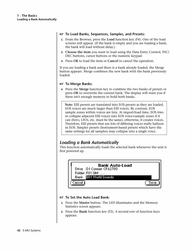
1 - The BasicsLoading a Bank Automatically
v To Load Banks, Sequences, Samples, and Presets:1. From the Browser, press the Load function key (F4). One of the load
screens will appear. (If the bank is empty and you are loading a bank, the bank will load without delay.)
2. Choose the item you want to load using the Data Entry Control, INC/DEC buttons, cursor buttons or the numeric keypad.
3. Press OK to load the item or Cancel to cancel the operation.
If you are loading a bank and there is a bank already loaded, the Merge button appears. Merge combines the new bank with the bank previously loaded.
v To Merge Banks:4. Press the Merge function key to combine the two banks of presets or
press OK to overwrite the current bank. The display will warn you if there isn't enough memory to hold both banks.
Note: EIII presets are translated into EOS presets as they are loaded. EOS voices are much larger than EIII voices. By contrast, EOS sample zones within voices are tiny. At import/load time, EOS tries to collapse adjacent EIII voices into EOS voice+sample zones if it can (Envs, LFOs, etc. must be the same), otherwise, it creates voices. Therefore, EIII presets that use lots of differing voices really balloon in EOS. Simpler presets (Instrument-based presets which have the same settings for all samples) may collapse into a single voice.
Loading a Bank AutomaticallyThis function automatically loads the selected bank whenever the unit is first powered up.
v To Set the Auto Load Bank:1. Press the Master button. The LED illuminates and the Memory
Statistics screen appears.
2. Press the Bank function key (F2). A second row of function keys appears.
42 E-MU Systems
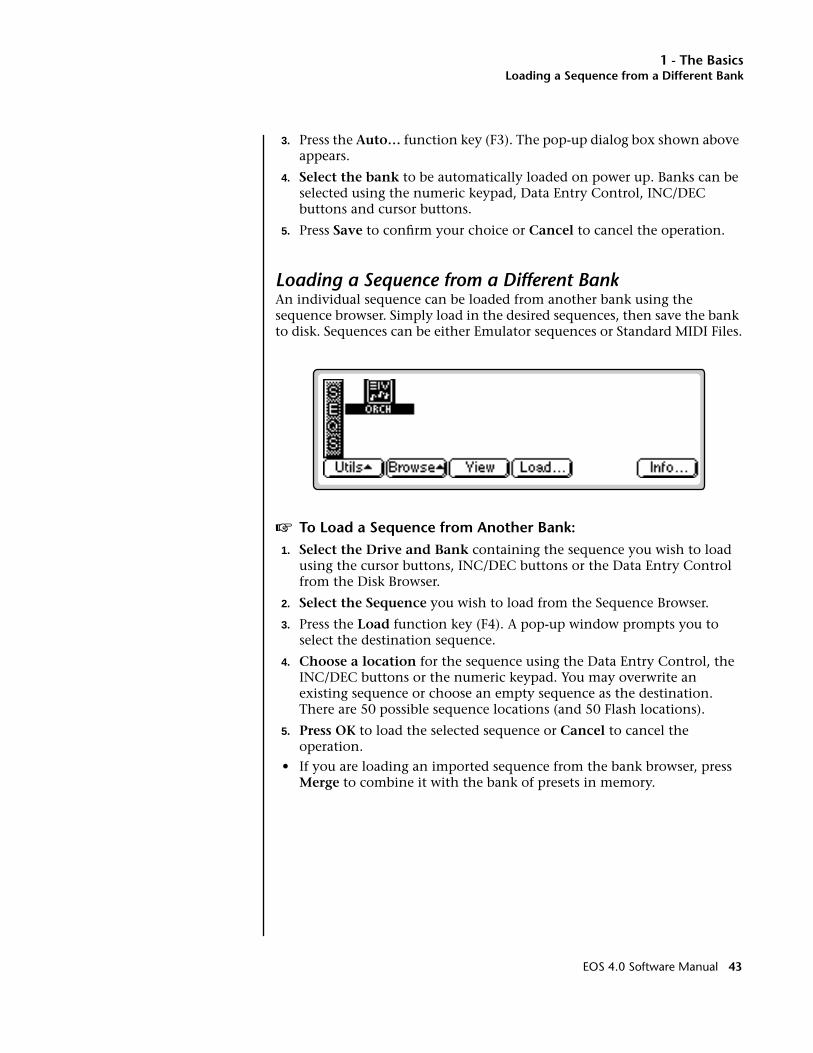
1 - The BasicsLoading a Sequence from a Different Bank
3. Press the Auto… function key (F3). The pop-up dialog box shown above appears.
4. Select the bank to be automatically loaded on power up. Banks can be selected using the numeric keypad, Data Entry Control, INC/DEC buttons and cursor buttons.
5. Press Save to confirm your choice or Cancel to cancel the operation.
Loading a Sequence from a Different BankAn individual sequence can be loaded from another bank using the sequence browser. Simply load in the desired sequences, then save the bank to disk. Sequences can be either Emulator sequences or Standard MIDI Files.
v To Load a Sequence from Another Bank:1. Select the Drive and Bank containing the sequence you wish to load
using the cursor buttons, INC/DEC buttons or the Data Entry Control from the Disk Browser.
2. Select the Sequence you wish to load from the Sequence Browser.
3. Press the Load function key (F4). A pop-up window prompts you to select the destination sequence.
4. Choose a location for the sequence using the Data Entry Control, the INC/DEC buttons or the numeric keypad. You may overwrite an existing sequence or choose an empty sequence as the destination. There are 50 possible sequence locations (and 50 Flash locations).
5. Press OK to load the selected sequence or Cancel to cancel the operation.
• If you are loading an imported sequence from the bank browser, press Merge to combine it with the bank of presets in memory.
EOS 4.0 Software Manual 43
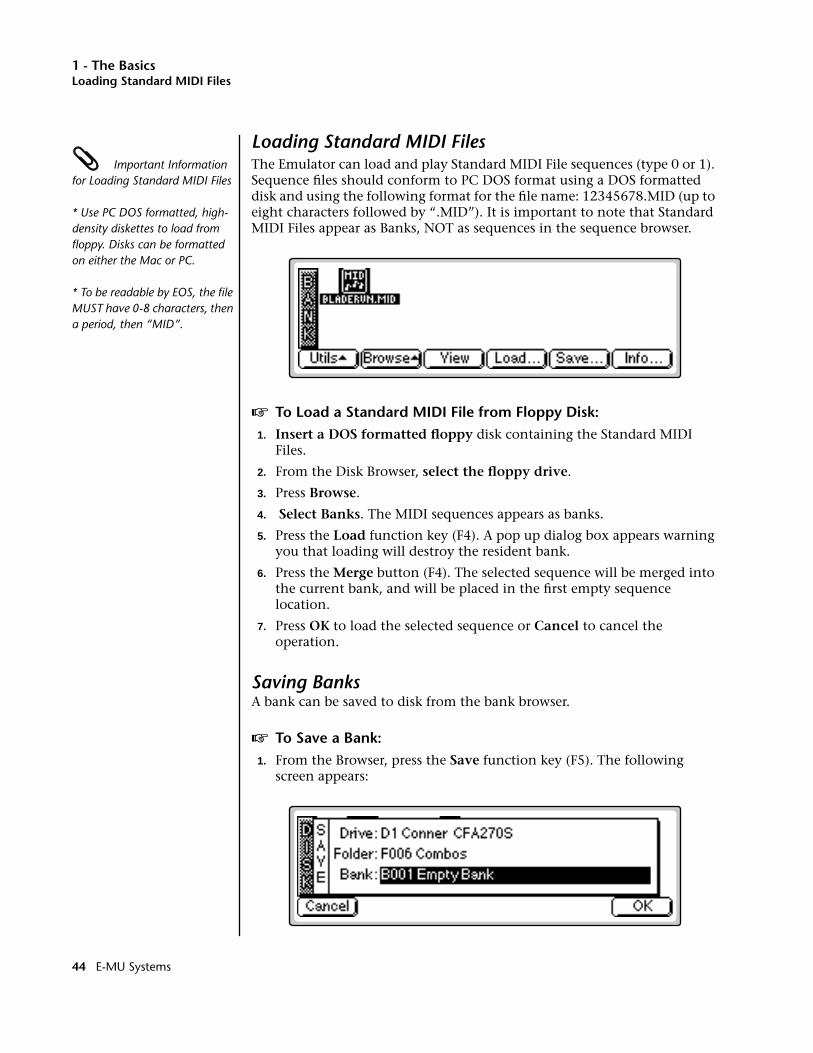
1 - The BasicsLoading Standard MIDI Files
Loading Standard MIDI Files Important Information for Loading Standard MIDI Files
* Use PC DOS formatted, high-density diskettes to load from floppy. Disks can be formatted on either the Mac or PC.
* To be readable by EOS, the file MUST have 0-8 characters, then a period, then “MID”.
The Emulator can load and play Standard MIDI File sequences (type 0 or 1). Sequence files should conform to PC DOS format using a DOS formatted disk and using the following format for the file name: 12345678.MID (up to eight characters followed by “.MID”). It is important to note that Standard MIDI Files appear as Banks, NOT as sequences in the sequence browser.
v To Load a Standard MIDI File from Floppy Disk:1. Insert a DOS formatted floppy disk containing the Standard MIDI
Files.
2. From the Disk Browser, select the floppy drive.
3. Press Browse.
4. Select Banks. The MIDI sequences appears as banks.
5. Press the Load function key (F4). A pop up dialog box appears warning you that loading will destroy the resident bank.
6. Press the Merge button (F4). The selected sequence will be merged into the current bank, and will be placed in the first empty sequence location.
7. Press OK to load the selected sequence or Cancel to cancel the operation.
Saving BanksA bank can be saved to disk from the bank browser.
v To Save a Bank:1. From the Browser, press the Save function key (F5). The following
screen appears:
44 E-MU Systems
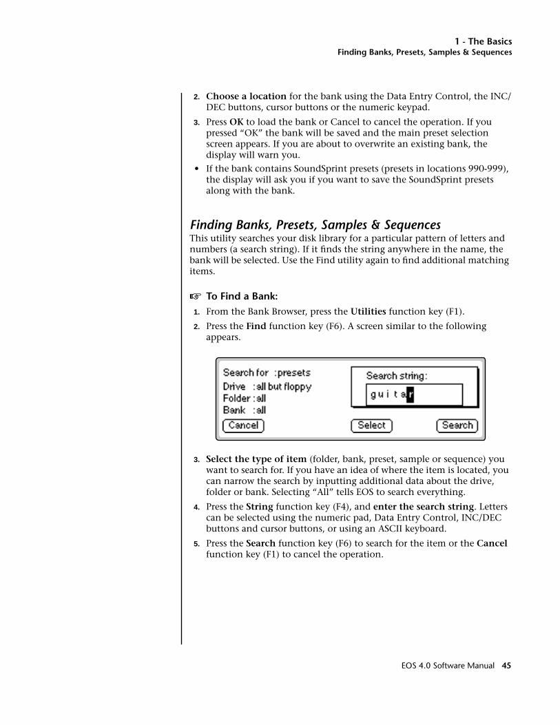
1 - The BasicsFinding Banks, Presets, Samples & Sequences
2. Choose a location for the bank using the Data Entry Control, the INC/DEC buttons, cursor buttons or the numeric keypad.
3. Press OK to load the bank or Cancel to cancel the operation. If you pressed “OK” the bank will be saved and the main preset selection screen appears. If you are about to overwrite an existing bank, the display will warn you.
• If the bank contains SoundSprint presets (presets in locations 990-999), the display will ask you if you want to save the SoundSprint presets along with the bank.
Finding Banks, Presets, Samples & SequencesThis utility searches your disk library for a particular pattern of letters and numbers (a search string). If it finds the string anywhere in the name, the bank will be selected. Use the Find utility again to find additional matching items.
v To Find a Bank:1. From the Bank Browser, press the Utilities function key (F1).
2. Press the Find function key (F6). A screen similar to the following appears.
3. Select the type of item (folder, bank, preset, sample or sequence) you want to search for. If you have an idea of where the item is located, you can narrow the search by inputting additional data about the drive, folder or bank. Selecting “All” tells EOS to search everything.
4. Press the String function key (F4), and enter the search string. Letters can be selected using the numeric pad, Data Entry Control, INC/DEC buttons and cursor buttons, or using an ASCII keyboard.
5. Press the Search function key (F6) to search for the item or the Cancel function key (F1) to cancel the operation.
EOS 4.0 Software Manual 45
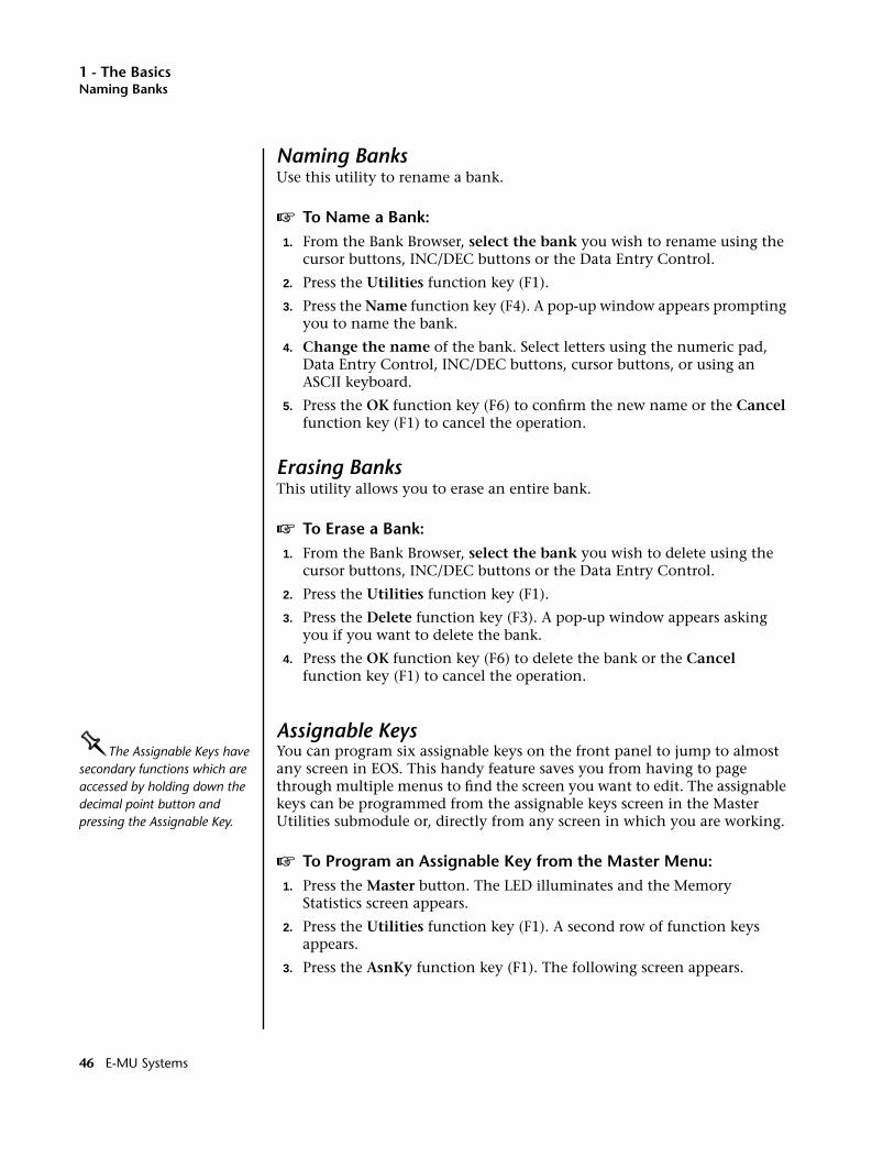
1 - The BasicsNaming Banks
Naming BanksUse this utility to rename a bank.
v To Name a Bank:1. From the Bank Browser, select the bank you wish to rename using the
cursor buttons, INC/DEC buttons or the Data Entry Control.
2. Press the Utilities function key (F1).
3. Press the Name function key (F4). A pop-up window appears prompting you to name the bank.
4. Change the name of the bank. Select letters using the numeric pad, Data Entry Control, INC/DEC buttons, cursor buttons, or using an ASCII keyboard.
5. Press the OK function key (F6) to confirm the new name or the Cancel function key (F1) to cancel the operation.
Erasing BanksThis utility allows you to erase an entire bank.
v To Erase a Bank:1. From the Bank Browser, select the bank you wish to delete using the
cursor buttons, INC/DEC buttons or the Data Entry Control.
2. Press the Utilities function key (F1).
3. Press the Delete function key (F3). A pop-up window appears asking you if you want to delete the bank.
4. Press the OK function key (F6) to delete the bank or the Cancel function key (F1) to cancel the operation.
Assignable KeysOOOOThe Assignable Keys have secondary functions which are accessed by holding down the decimal point button and pressing the Assignable Key.
You can program six assignable keys on the front panel to jump to almost any screen in EOS. This handy feature saves you from having to page through multiple menus to find the screen you want to edit. The assignable keys can be programmed from the assignable keys screen in the Master Utilities submodule or, directly from any screen in which you are working.
v To Program an Assignable Key from the Master Menu:1. Press the Master button. The LED illuminates and the Memory
Statistics screen appears.
2. Press the Utilities function key (F1). A second row of function keys appears.
3. Press the AsnKy function key (F1). The following screen appears.
46 E-MU Systems
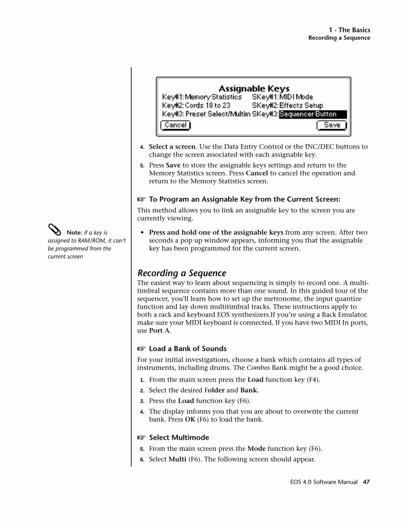
1 - The BasicsRecording a Sequence
4. Select a screen. Use the Data Entry Control or the INC/DEC buttons to change the screen associated with each assignable key.
5. Press Save to store the assignable keys settings and return to the Memory Statistics screen. Press Cancel to cancel the operation and return to the Memory Statistics screen.
v To Program an Assignable Key from the Current Screen:This method allows you to link an assignable key to the screen you are currently viewing.
Note: if a key is assigned to RAM/ROM, it can’t be programmed from the current screen
• Press and hold one of the assignable keys from any screen. After two seconds a pop up window appears, informing you that the assignable key has been programmed for the current screen.
Recording a SequenceThe easiest way to learn about sequencing is simply to record one. A multi-timbral sequence contains more than one sound. In this guided tour of the sequencer, you'll learn how to set up the metronome, the input quantize function and lay down multitimbral tracks. These instructions apply to both a rack and keyboard EOS synthesizers.If you’re using a Rack Emulator. make sure your MIDI keyboard is connected. If you have two MIDI In ports, use Port A.
v Load a Bank of SoundsFor your initial investigations, choose a bank which contains all types of instruments, including drums. The Combos Bank might be a good choice.
1. From the main screen press the Load function key (F4).
2. Select the desired Folder and Bank.
3. Press the Load function key (F6).
4. The display informs you that you are about to overwrite the current bank. Press OK (F6) to load the bank.
v Select Multimode5. From the main screen press the Mode function key (F6).
6. Select Multi (F6). The following screen should appear.
EOS 4.0 Software Manual 47

1 - The BasicsRecording a Sequence
• There are two different Multimode screen views. If you get the other screen, press the F6 function key, then press View (F3).
v Enter the Sequencer Submodule7. Hold the Decimal Point button and press Assignable Key 1. The
Sequence Manage screen appears.
8. Press the Edit function key (F5). The Edit screen appears.
v Set up the MetronomeThe Metronome is important if you want to use the Quantize functions. If you don't want quantization and just want to enter a few tracks, skip to step 20.
9. Press the Setup button (F3). A second row of function keys appears.
10. Press the Metro button (F1). The following screen appears.
11. Set the Metronome parameters as shown.
12. The lower left field allows you to select a preset to be used for the Metronome. Select a preset containing a click or short percussion sound.
13. Move the cursor to the MIDI Note/Ch field.
14. Select the metronome sound using the Data Entry Control, INC/DEC buttons or the keyboard. The metronome sound is played as you scroll through the note numbers.
15. Press the Exit button to leave the Metronome screen.
48 E-MU Systems
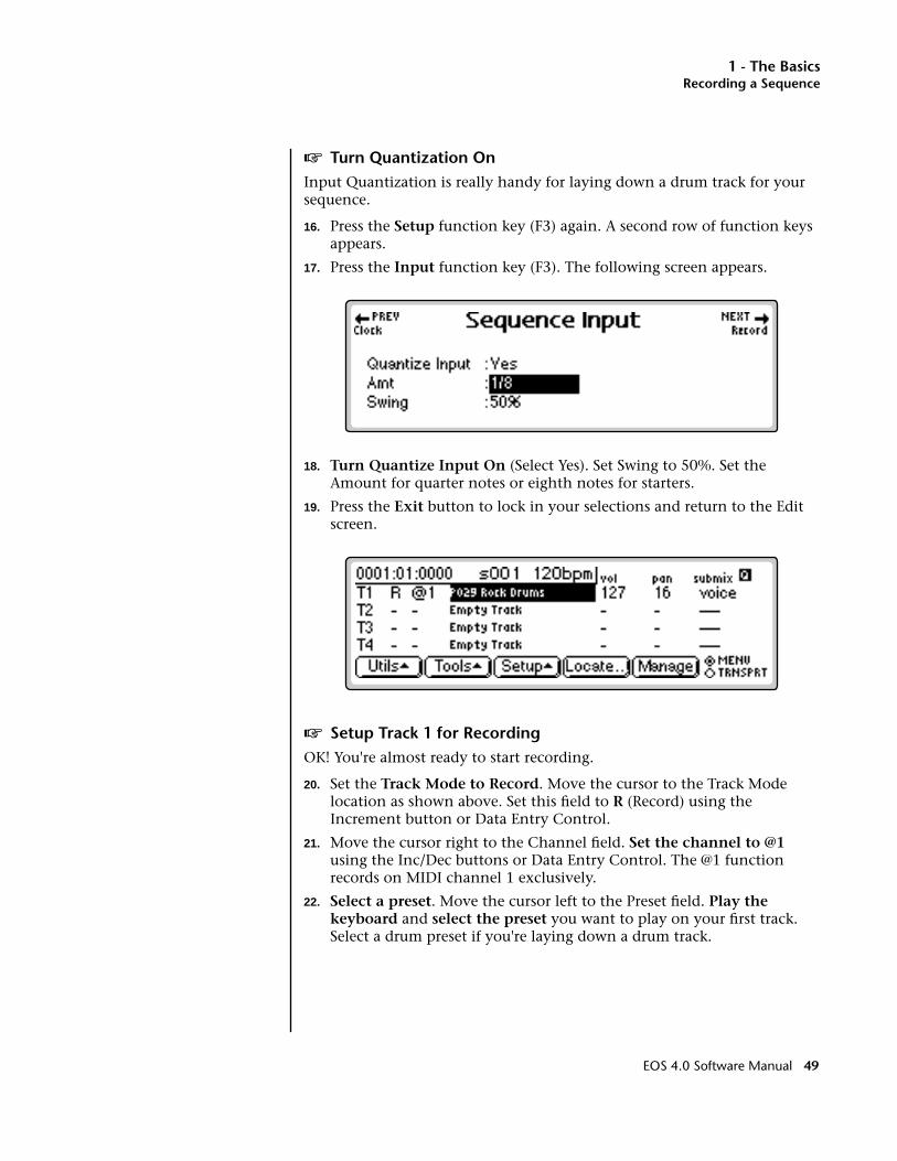
1 - The BasicsRecording a Sequence
v Turn Quantization OnInput Quantization is really handy for laying down a drum track for your sequence.
16. Press the Setup function key (F3) again. A second row of function keys appears.
17. Press the Input function key (F3). The following screen appears.
18. Turn Quantize Input On (Select Yes). Set Swing to 50%. Set the Amount for quarter notes or eighth notes for starters.
19. Press the Exit button to lock in your selections and return to the Edit screen.
v Setup Track 1 for RecordingOK! You're almost ready to start recording.
20. Set the Track Mode to Record. Move the cursor to the Track Mode location as shown above. Set this field to R (Record) using the Increment button or Data Entry Control.
21. Move the cursor right to the Channel field. Set the channel to @1 using the Inc/Dec buttons or Data Entry Control. The @1 function records on MIDI channel 1 exclusively.
22. Select a preset. Move the cursor left to the Preset field. Play the keyboard and select the preset you want to play on your first track. Select a drum preset if you're laying down a drum track.
EOS 4.0 Software Manual 49

1 - The BasicsArpeggiator Sequencing!
v Record Track 123. Press the Menu/Transport function key (F6). The Transport control
buttons appear on the lower line of the display.
24. Get ready to record! Press the Record function key (F4).
25. Press the Play function key (F3) to begin recording. You should be hearing the metronome.
26. Start playing. If you make a serious mistake in your playing and want to try again, press Abort (F5). Then press Record, then Play to begin again.
27. Press the Stop function key (F2) to end recording. Press RTZ (F1) to rewind to the beginning of the sequence. Press Play (F3) to play back your creation.
• Note that the Track Status field for Track 1 now reads P for playback. The track can also be set to M to Mute the track if you don't want to hear it.
v Record Another Track28. Set Track 2 to Record. Move the cursor to the record field of track 2
and set the track to R (record).
29. Move the cursor to the channel field of track 2 and set the channel to @2. This will force all information onto MIDI channel 2.
30. Move the cursor back to the preset field on track 2 and select a preset.
31. You’re ready to record track 2. Follow the instructions for recording on track 1 and GO!
Arpeggiator Sequencing!One of the many things you can do with EOS is combine the Arpeggiator and the Sequencer. This is a great idea stimulator and tons of fun.
v Load a Bank of Sounds (E-Synth - jump to step 5)1. From the main screen press the Load function key (F4).
2. Select the desired Folder and Bank.
3. Press the Load function key (F6).
4. The display informs you that you are about to overwrite the current bank. Press OK (F6) to load the bank.
v Select Multimode5. From the main screen press the Mode function key (F6).
6. Select Multi (F6). The following screen appears.
50 E-MU Systems
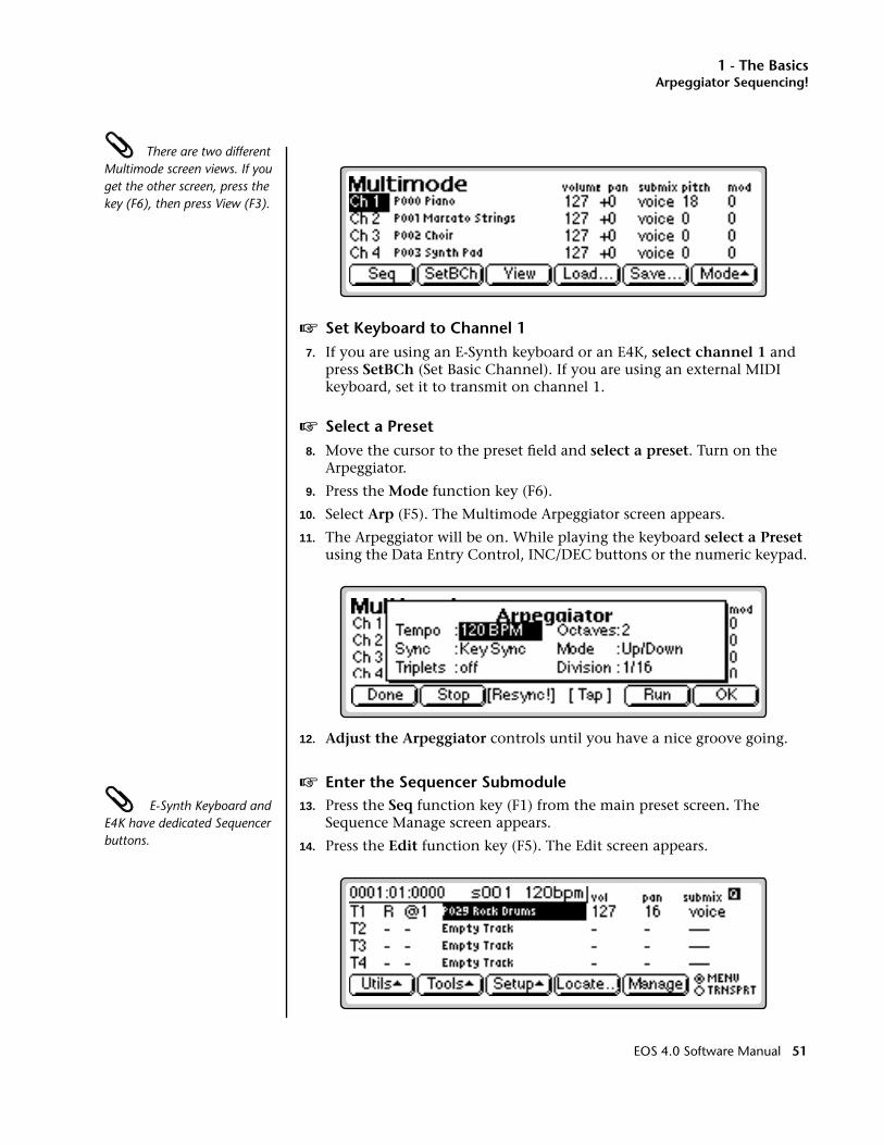
1 - The BasicsArpeggiator Sequencing!
There are two different Multimode screen views. If you get the other screen, press the key (F6), then press View (F3).
v Set Keyboard to Channel 17. If you are using an E-Synth keyboard or an E4K, select channel 1 and
press SetBCh (Set Basic Channel). If you are using an external MIDI keyboard, set it to transmit on channel 1.
v Select a Preset8. Move the cursor to the preset field and select a preset. Turn on the
Arpeggiator.
9. Press the Mode function key (F6).
10. Select Arp (F5). The Multimode Arpeggiator screen appears.
11. The Arpeggiator will be on. While playing the keyboard select a Preset using the Data Entry Control, INC/DEC buttons or the numeric keypad.
12. Adjust the Arpeggiator controls until you have a nice groove going.
v Enter the Sequencer Submodule E-Synth Keyboard and E4K have dedicated Sequencer buttons.
13. Press the Seq function key (F1) from the main preset screen. The Sequence Manage screen appears.
14. Press the Edit function key (F5). The Edit screen appears.
EOS 4.0 Software Manual 51

1 - The BasicsArpeggiator Sequencing!
v Setup Track 1 for RecordingAlmost ready to start recording…
15. Set the Track Mode to Record. Move the cursor to the Track Mode location as shown above. Set this field to R (Record) using the Increment button or Data Entry Control.
OOOO Since you've already selected a preset for MIDI channel 1 in Multimode, the preset will automatically come up when you set @1 as the channel number.
16. Move the cursor right to the Channel field. Set the channel to @1 using the Inc/Dec buttons or Data Entry Control. The @1 function records on MIDI channel 1 exclusively.
17. Play the keyboard. You should be hearing the arpeggiator playing the preset you selected.
v Record Track 118. Press the Menu/Transport function key (F6). The Transport control
keys appear on the lower line of the display.
19. Get ready to record! Press Record (F4), then Play (F3) to begin recording.
20. Start playing.
21. Press Stop (F2) to end recording. Press RTZ (F1) to rewind to the beginning of the sequence. Press Play (F3) to play back your creation.
v Turn the Arpeggiator Off22. Note that the arpeggiated sequence is being arpeggiated again! Press the
Stop function key (F2), then press the Exit button to return to the Multimode screen.
23. Press the Mode function key (F6).
24. Select Arp (F5). The Multimode Arpeggiator screen appears.
25. Press Stop (F2) to stop the arpeggiator.
26. Press OK (F6) or Done (F1) to return to the Multimode screen.
v Back to the Sequencer…27. Hold the Decimal Point button and press Assignable Key 1. The
Sequence Manage screen appears.
28. Press the Menu/Transport function key (F6). The Transport control keys appear on the lower line of the display.
29. Press Play (F3) to play the sequence. Yeah!
v Record More Tracks?30. Repeat steps 15-21 changing the MIDI channel for each subsequent
track.
52 E-MU Systems

1 - The BasicsA Practice Sampling Session
You can also record additional tracks using the arpeggiator. To do this you must match the MIDI channel generated by the keyboard to the MIDI channel of the track you wish to record. Use Set Kybd on E-Synth or E4K. If you are using an external MIDI keyboard, change the MIDI channel output from the keyboard to the same channel you are recording on the track.
A Practice Sampling SessionSampling lets you play ANY SOUND! In this session, you will sample your own voice. Although there is much more to the art of sampling than just sampling your voice, this lesson will give you a good start.
In preparation for this sampling session, please read over Chapter 5, Sample Management.
v Connections…1. Connect a microphone to the left sample input jack on the rear panel
of your EOS instrument. If you don't have a microphone you can use another signal source such as a CD player. Connect a CD player to both the left and right sample inputs or just the left input if you want to sample in mono.
v Erase the BankThis step “cleans the slate” for your experiments.
2. Press the Master button to enter the Master module.
3. Press the Bank function key (F2).
4. Press Erase (F1). A popup dialog box appears asking you if you want to erase Preset, Samples and Sequences.
5. Don't worry, be happy! Press OK (F6).
v Sample Setup6. Press the Sample Manage button.
7. Press the New function key (F3). The following screen appears.
8. If you are sampling in mono, select the Left channel only. The Threshold sample trigger only reads the Left channel.
EOS 4.0 Software Manual 53
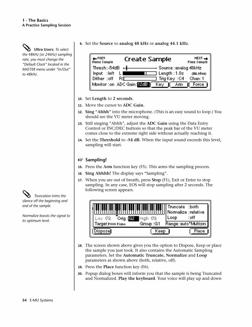
1 - The BasicsA Practice Sampling Session
9. Set the Source to analog 48 kHz or analog 44.1 kHz. Ultra Users: To select the 48kHz (or 24kHz) sampling rate, you must change the “Default Clock” located in the MASTER menu under “In/Out” to 48kHz.
10. Set Length to 2 seconds.
11. Move the cursor to ADC Gain.
12. Sing “Ahhh” into the microphone. (This is an easy sound to loop.) You should see the VU meter moving.
13. Still singing “Ahhh”, adjust the ADC Gain using the Data Entry Control or INC/DEC buttons so that the peak bar of the VU meter comes close to the extreme right side without actually reaching it.
14. Set the Threshold to -54 dB. When the input sound exceeds this level, sampling will start.
v Sampling!15. Press the Arm function key (F5). This arms the sampling process.
16. Sing Ahhhh! The display says “Sampling”.
17. When you are out of breath, press Stop (F1), Exit or Enter to stop sampling. In any case, EOS will stop sampling after 2 seconds. The following screen appears.
Truncation trims the silence off the beginning and end of the sample.
Normalize boosts the signal to its optimum level.
18. The screen shown above gives you the option to Dispose, Keep or place the sample you just took. It also contains the Automatic Sampling parameters. Set the Automatic Truncate, Normalize and Loop parameters as shown above (both, relative, off).
19. Press the Place function key (F6).
20. Popup dialog boxes will inform you that the sample is being Truncated and Normalized. Play the keyboard. Your voice will play up and down
54 E-MU Systems
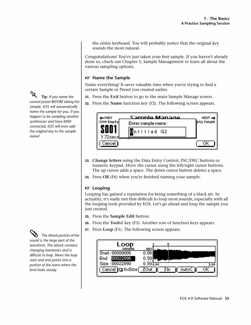
1 - The BasicsA Practice Sampling Session
the entire keyboard. You will probably notice that the original key sounds the most natural.
Congratulations! You've just taken your first sample. If you haven't already done so, check out Chapter 5, Sample Management to learn all about the various sampling options.
v Name the SampleName everything! It saves valuable time when you're trying to find a certain Sample or Preset you created earlier.
OOOO Tip: If you name the current preset BEFORE taking the sample, EOS will automatically name the sample for you. If you happen to be sampling another synthesizer and have MIDI connected, EOS will even add the original key to the sample name!
21. Press the Exit button to go to the main Sample Manage screen.
22. Press the Name function key (F2). The following screen appears.
23. Change letters using the Data Entry Control, INC/DEC buttons or numeric keypad. Move the cursor using the left/right cursor buttons. The up cursor adds a space. The down cursor button deletes a space.
24. Press OK (F6) when you're finished naming your sample.
v LoopingLooping has gained a reputation for being something of a black art. In actuality, it's really not that difficult to loop most sounds, especially with all the looping tools provided by EOS. Let's go ahead and loop the sample you just created.
25. Press the Sample Edit button.
26. Press the Tools1 key (F3). Another row of function keys appears.
27. Press Loop (F1). The following screen appears. The Attack portion of the sound is the large part of the waveform. The attack contains changing harmonics and is difficult to loop. Move the loop start and end points into a portion of the wave where the level looks steady.
EOS 4.0 Software Manual 55
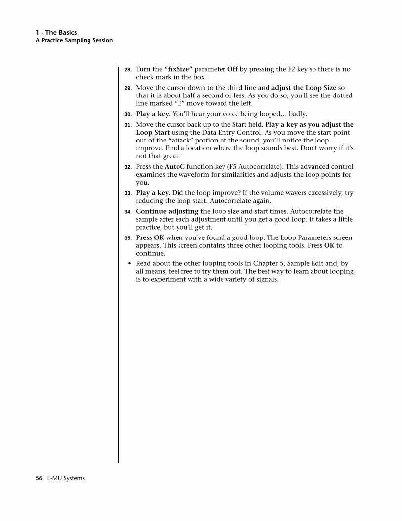
1 - The BasicsA Practice Sampling Session
28. Turn the “fixSize” parameter Off by pressing the F2 key so there is no check mark in the box.
29. Move the cursor down to the third line and adjust the Loop Size so that it is about half a second or less. As you do so, you'll see the dotted line marked “E” move toward the left.
30. Play a key. You'll hear your voice being looped… badly.
31. Move the cursor back up to the Start field. Play a key as you adjust the Loop Start using the Data Entry Control. As you move the start point out of the “attack” portion of the sound, you’ll notice the loop improve. Find a location where the loop sounds best. Don't worry if it's not that great.
32. Press the AutoC function key (F5 Autocorrelate). This advanced control examines the waveform for similarities and adjusts the loop points for you.
33. Play a key. Did the loop improve? If the volume wavers excessively, try reducing the loop start. Autocorrelate again.
34. Continue adjusting the loop size and start times. Autocorrelate the sample after each adjustment until you get a good loop. It takes a little practice, but you'll get it.
35. Press OK when you've found a good loop. The Loop Parameters screen appears. This screen contains three other looping tools. Press OK to continue.
• Read about the other looping tools in Chapter 5, Sample Edit and, by all means, feel free to try them out. The best way to learn about looping is to experiment with a wide variety of signals.
56 E-MU Systems

1 - The BasicsExploring the Preset
Exploring the PresetThe Preset Edit module is where everything comes together into a complete keyboard setup. It's a huge module and can be initially confusing. The first thing you need to know is that there are two main levels to the Preset Edit module.
Preset Definition is used for arranging voices and samples on the keyboard, editing global preset parameters and linking presets, as well as setting effects and initial controller values.
OOOO Use the EXIT button to back out of the Preset Edit module if you get lost.
Dynamic Processing is the lower level which is used to perform more detailed editing of voices such as envelope shaping of the amplifier and filter as well as the modulation parameters. This is the “synthesizer” section of EOS.
The Preset Definition layer contains three main pages.
Global Editor. Preset Transpose, Volume and Preset Effects.
Links. Create stacked preset layers or splits.
Voice Editor. Allows you place voices and samples on the keyboard and crossfade or switch between them according to key position, velocity range and realtime controls. Also contains voice tuning, volume and pan controls.
The Dynamic Processing parameters are accessed by pressing the Edit button while in one of the Preset Edit, Voice screen parameters.
Preset Edit Key
GlobalPreset SetupPreset EffectsInit. Controller
LinksVol/Pan/TuneKey RangesVelocity Ranges
VoicesVol/Pan/TuneKey RangesVelocity RangesRealtime Ranges
TuningVoice TuningVoice ModifiersVoice Setup
Amp/FilterAmplifierAmp. EnvelopeFilter SetupFilter Envelope
LFO/AuxLFO-1LFO-2Aux. Envelope
CordsCords 00-05Cords 06-11Cords 12-17Cords 18-23
Dynamic Processing Level
Preset Definition Level
Exit Key
Edit Soft Key
EOS 4.0 Software Manual 57
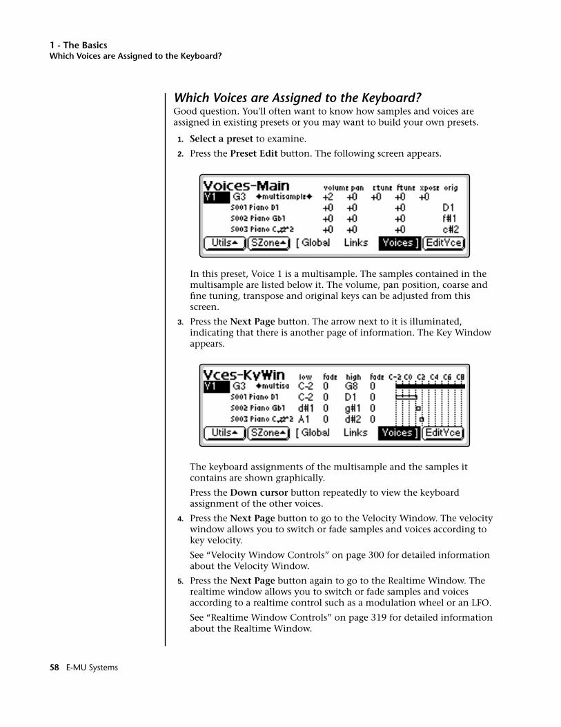
1 - The BasicsWhich Voices are Assigned to the Keyboard?
Which Voices are Assigned to the Keyboard?Good question. You'll often want to know how samples and voices are assigned in existing presets or you may want to build your own presets.
1. Select a preset to examine.
2. Press the Preset Edit button. The following screen appears.
In this preset, Voice 1 is a multisample. The samples contained in the multisample are listed below it. The volume, pan position, coarse and fine tuning, transpose and original keys can be adjusted from this screen.
3. Press the Next Page button. The arrow next to it is illuminated, indicating that there is another page of information. The Key Window appears.
The keyboard assignments of the multisample and the samples it contains are shown graphically.
Press the Down cursor button repeatedly to view the keyboard assignment of the other voices.
4. Press the Next Page button to go to the Velocity Window. The velocity window allows you to switch or fade samples and voices according to key velocity.
See “Velocity Window Controls” on page 300 for detailed information about the Velocity Window.
5. Press the Next Page button again to go to the Realtime Window. The realtime window allows you to switch or fade samples and voices according to a realtime control such as a modulation wheel or an LFO.
See “Realtime Window Controls” on page 319 for detailed information about the Realtime Window.
58 E-MU Systems
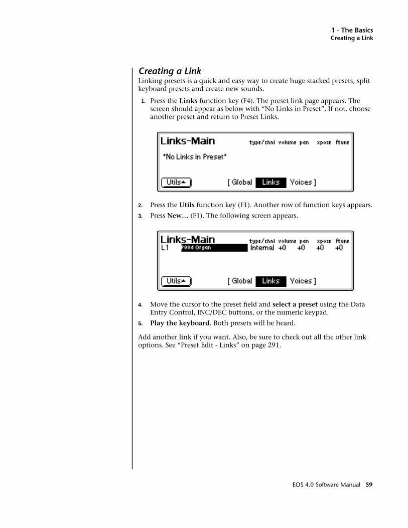
1 - The BasicsCreating a Link
Creating a LinkLinking presets is a quick and easy way to create huge stacked presets, split keyboard presets and create new sounds.
1. Press the Links function key (F4). The preset link page appears. The screen should appear as below with “No Links in Preset”. If not, choose another preset and return to Preset Links.
2. Press the Utils function key (F1). Another row of function keys appears.
3. Press New… (F1). The following screen appears.
4. Move the cursor to the preset field and select a preset using the Data Entry Control, INC/DEC buttons, or the numeric keypad.
5. Play the keyboard. Both presets will be heard.
Add another link if you want. Also, be sure to check out all the other link options. See “Preset Edit - Links” on page 291.
EOS 4.0 Software Manual 59

1 - The Basics
60 E-MU Systems
2 - Master Menu
2Master Menu
EOS 4.0 Software Manual 61

2 - Master Menu
62 E-MU Systems

Overview
The Master Module commands affect the Emulator on a global basis (all presets). Master operations affect overall tuning, LCD contrast and Master Effects to name a few. All of the settings defined in the Master Menu (with the exception of a few of the Sequencer settings) are saved into Flash RAM when you exit the module, meaning the settings are stored even when you turn off the unit.
This chapter describes the global settings, features and commands you can carry out using the Master Menu. The sections in this chapter are organized by submenu as they appear in the Master Menu.
The Master Menu contains six main submenus:
Utilities. Controls for the assignable keys, test tones and volume control recalibration. Also contains the channel status indicator, credits and software version display.
Bank. Allows you to name or erase the bank and set a bank to be auto-loaded on power-up. If you have Flash RAM or Flash ROM installed, the Bank submenu contains the Flash Utilities also.
Setup. Contains six submenus: Tune, Input/Output, Miscellaneous, SCSI, Import and Memory Configuration.
FX. Contains the digital effect processor functions.
Sequence Manage. Contains a 48-track sequencer.
MIDI. Contains global MIDI controls, velocity curve and other miscellaneous MIDI functions.
EOS 4.0 Software Manual 63
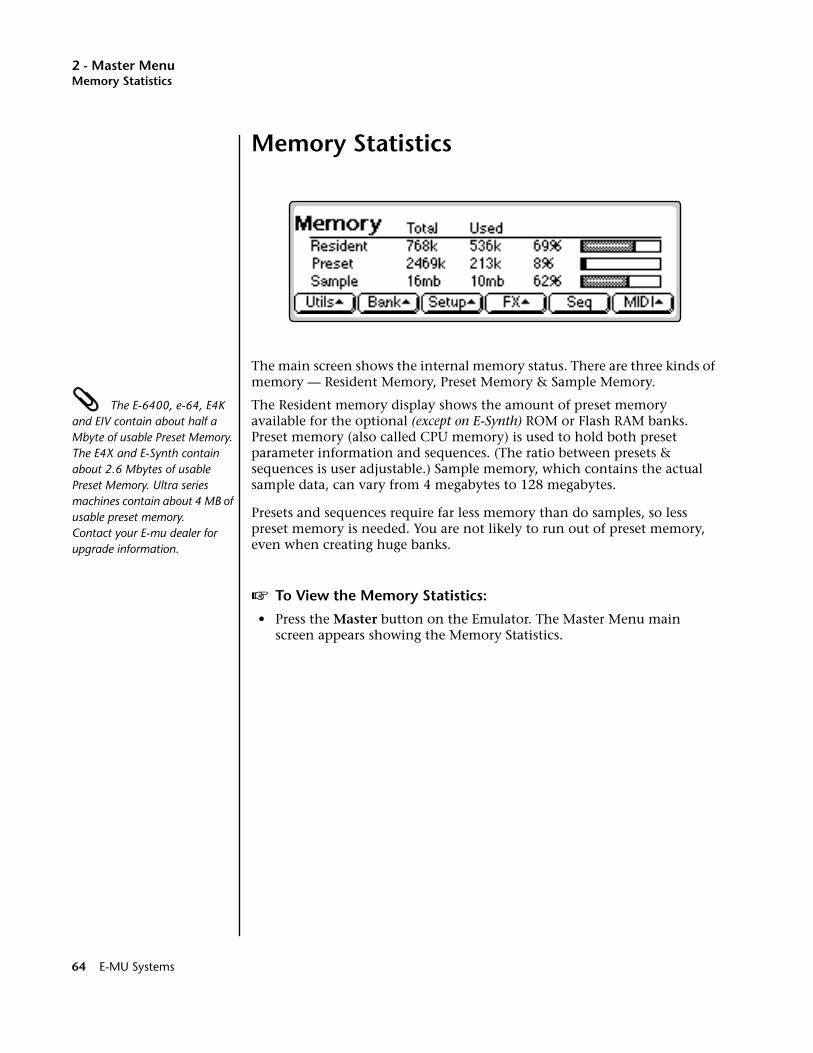
2 - Master MenuMemory Statistics
Memory Statistics
The main screen shows the internal memory status. There are three kinds of memory — Resident Memory, Preset Memory & Sample Memory.
The E-6400, e-64, E4K and EIV contain about half a Mbyte of usable Preset Memory. The E4X and E-Synth contain about 2.6 Mbytes of usable Preset Memory. Ultra series machines contain about 4 MB of usable preset memory. Contact your E-mu dealer for upgrade information.
The Resident memory display shows the amount of preset memory available for the optional (except on E-Synth) ROM or Flash RAM banks. Preset memory (also called CPU memory) is used to hold both preset parameter information and sequences. (The ratio between presets & sequences is user adjustable.) Sample memory, which contains the actual sample data, can vary from 4 megabytes to 128 megabytes.
Presets and sequences require far less memory than do samples, so less preset memory is needed. You are not likely to run out of preset memory, even when creating huge banks.
v To View the Memory Statistics:
• Press the Master button on the Emulator. The Master Menu main screen appears showing the Memory Statistics.
64 E-MU Systems
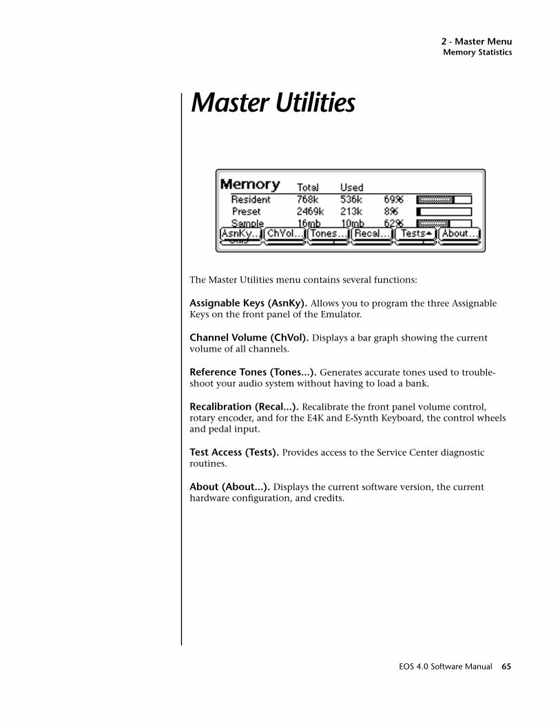
2 - Master MenuMemory Statistics
Master Utilities
The Master Utilities menu contains several functions:
Assignable Keys (AsnKy). Allows you to program the three Assignable Keys on the front panel of the Emulator.
Channel Volume (ChVol). Displays a bar graph showing the current volume of all channels.
Reference Tones (Tones...). Generates accurate tones used to trouble-shoot your audio system without having to load a bank.
Recalibration (Recal...). Recalibrate the front panel volume control, rotary encoder, and for the E4K and E-Synth Keyboard, the control wheels and pedal input.
Test Access (Tests). Provides access to the Service Center diagnostic routines.
About (About...). Displays the current software version, the current hardware configuration, and credits.
EOS 4.0 Software Manual 65
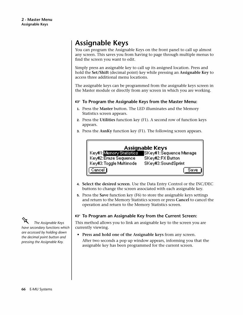
2 - Master MenuAssignable Keys
Assignable KeysYou can program the Assignable Keys on the front panel to call up almost any screen. This saves you from having to page through multiple menus to find the screen you want to edit.
Simply press an assignable key to call up its assigned location. Press and hold the Set/Shift (decimal point) key while pressing an Assignable Key to access three additional menu locations.
The assignable keys can be programmed from the assignable keys screen in the Master module or directly from any screen in which you are working.
v To Program the Assignable Keys from the Master Menu:
1. Press the Master button. The LED illuminates and the Memory Statistics screen appears.
2. Press the Utilities function key (F1). A second row of function keys appears.
3. Press the AsnKy function key (F1). The following screen appears.
4. Select the desired screen. Use the Data Entry Control or the INC/DEC buttons to change the screen associated with each assignable key.
5. Press the Save function key (F6) to store the assignable keys settings and return to the Memory Statistics screen or press Cancel to cancel the operation and return to the Memory Statistics screen.
v To Program an Assignable Key from the Current Screen:
OOOO The Assignable Keys have secondary functions which are accessed by holding down the decimal point button and pressing the Assignable Key.
This method allows you to link an assignable key to the screen you are currently viewing.
• Press and hold one of the Assignable keys from any screen.
After two seconds a pop up window appears, informing you that the assignable key has been programmed for the current screen.
66 E-MU Systems
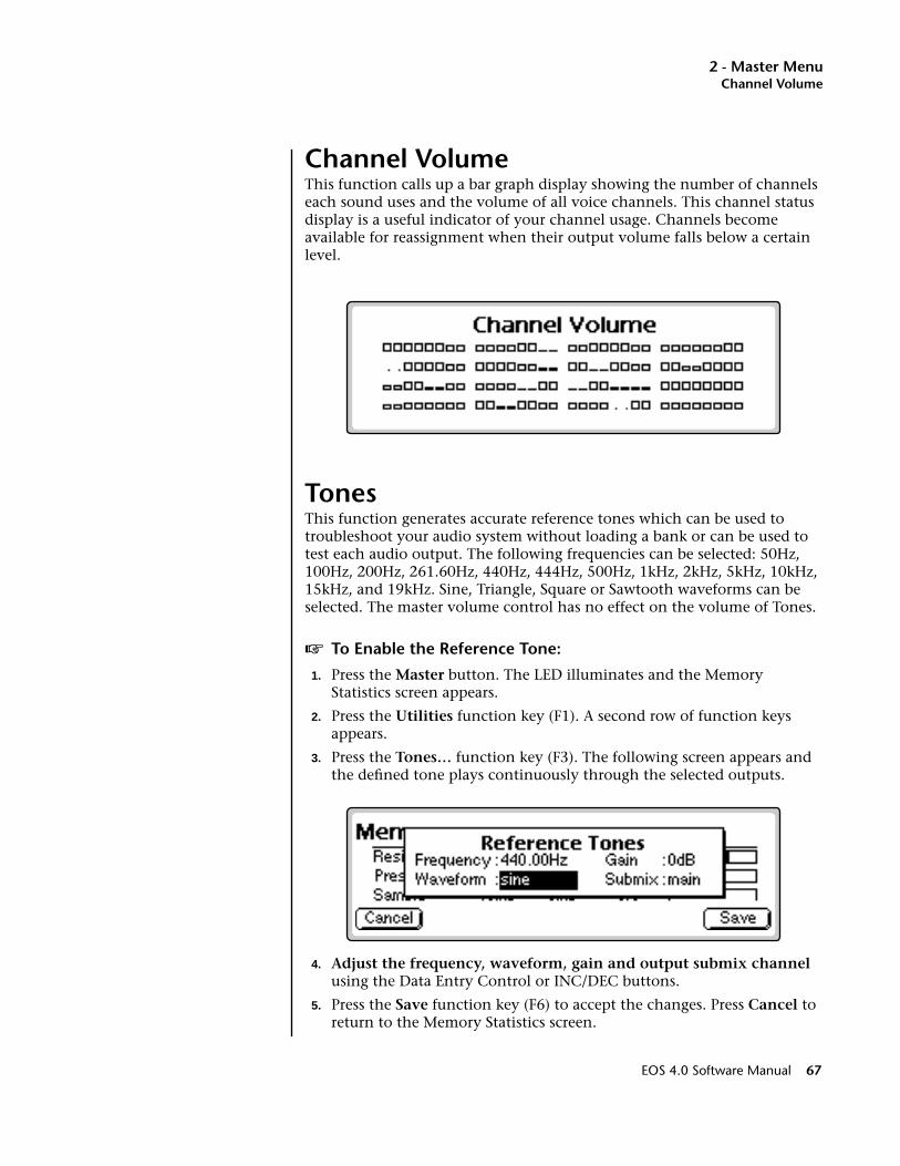
2 - Master MenuChannel Volume
Channel VolumeThis function calls up a bar graph display showing the number of channels each sound uses and the volume of all voice channels. This channel status display is a useful indicator of your channel usage. Channels become available for reassignment when their output volume falls below a certain level.
TonesThis function generates accurate reference tones which can be used to troubleshoot your audio system without loading a bank or can be used to test each audio output. The following frequencies can be selected: 50Hz, 100Hz, 200Hz, 261.60Hz, 440Hz, 444Hz, 500Hz, 1kHz, 2kHz, 5kHz, 10kHz, 15kHz, and 19kHz. Sine, Triangle, Square or Sawtooth waveforms can be selected. The master volume control has no effect on the volume of Tones.
v To Enable the Reference Tone:
1. Press the Master button. The LED illuminates and the Memory Statistics screen appears.
2. Press the Utilities function key (F1). A second row of function keys appears.
3. Press the Tones… function key (F3). The following screen appears and the defined tone plays continuously through the selected outputs.
4. Adjust the frequency, waveform, gain and output submix channel using the Data Entry Control or INC/DEC buttons.
5. Press the Save function key (F6) to accept the changes. Press Cancel to return to the Memory Statistics screen.
EOS 4.0 Software Manual 67
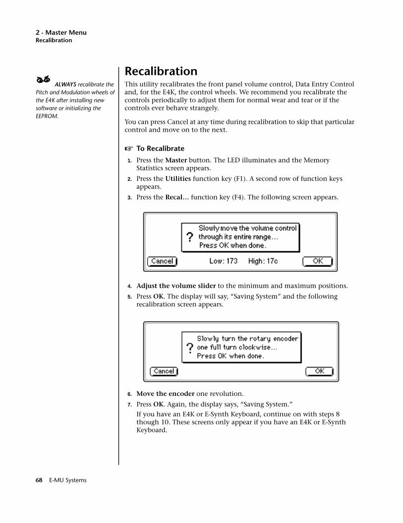
2 - Master MenuRecalibration
Recalibration____ ALWAYS recalibrate the Pitch and Modulation wheels of the E4K after installing new software or initializing the EEPROM.
This utility recalibrates the front panel volume control, Data Entry Control and, for the E4K, the control wheels. We recommend you recalibrate the controls periodically to adjust them for normal wear and tear or if the controls ever behave strangely.
You can press Cancel at any time during recalibration to skip that particular control and move on to the next.
v To Recalibrate
1. Press the Master button. The LED illuminates and the Memory Statistics screen appears.
2. Press the Utilities function key (F1). A second row of function keys appears.
3. Press the Recal… function key (F4). The following screen appears.
4. Adjust the volume slider to the minimum and maximum positions.
5. Press OK. The display will say, “Saving System” and the following recalibration screen appears.
6. Move the encoder one revolution.
7. Press OK. Again, the display says, “Saving System.”
If you have an E4K or E-Synth Keyboard, continue on with steps 8 though 10. These screens only appear if you have an E4K or E-Synth Keyboard.
68 E-MU Systems
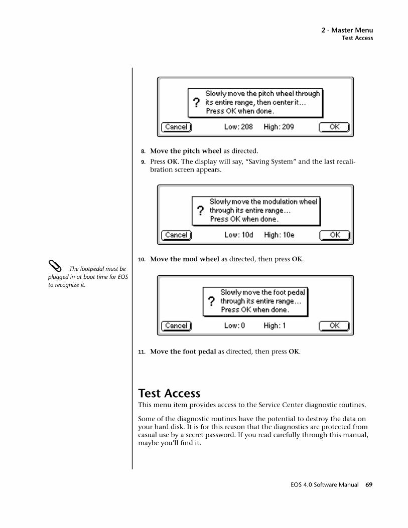
2 - Master MenuTest Access
8. Move the pitch wheel as directed.
9. Press OK. The display will say, “Saving System” and the last recali-bration screen appears.
10. Move the mod wheel as directed, then press OK. The footpedal must be plugged in at boot time for EOS to recognize it.
11. Move the foot pedal as directed, then press OK.
Test AccessThis menu item provides access to the Service Center diagnostic routines.
Some of the diagnostic routines have the potential to destroy the data on your hard disk. It is for this reason that the diagnostics are protected from casual use by a secret password. If you read carefully through this manual, maybe you’ll find it.
EOS 4.0 Software Manual 69
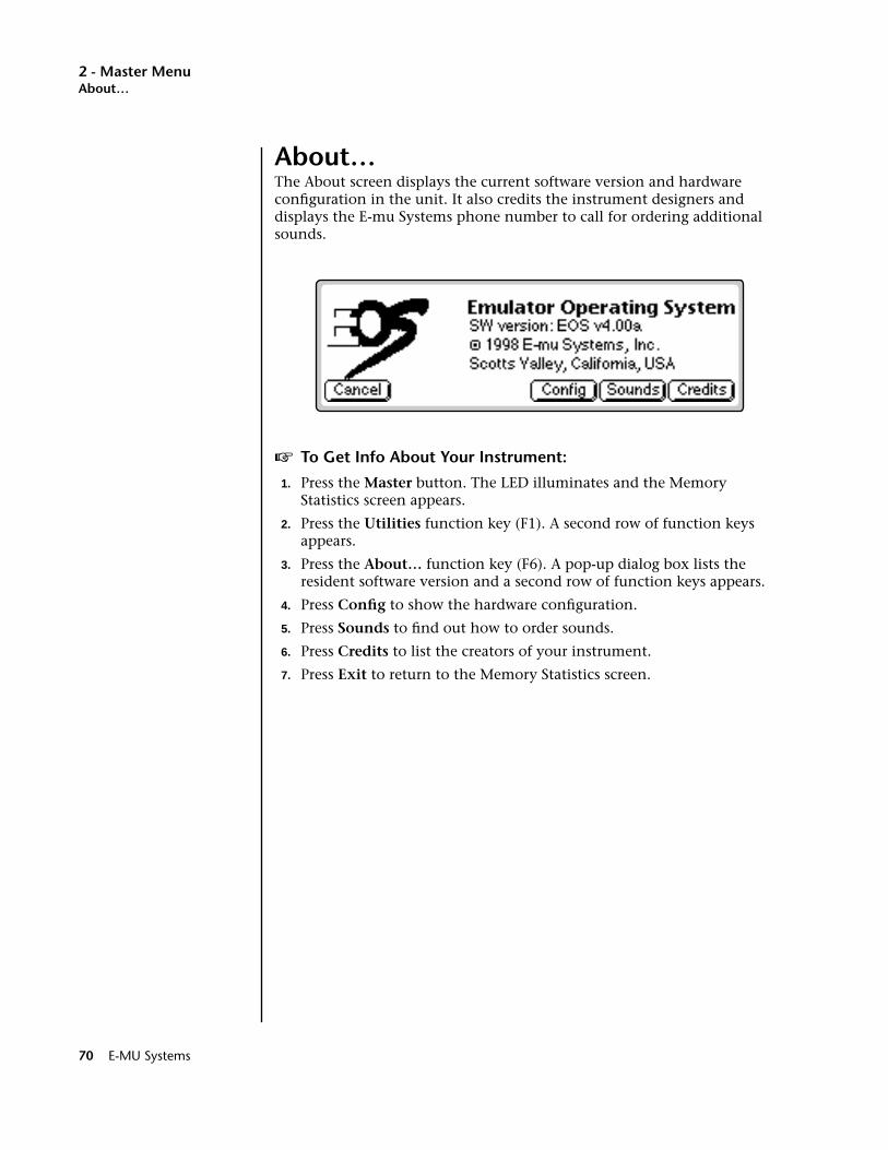
2 - Master MenuAbout…
About…The About screen displays the current software version and hardware configuration in the unit. It also credits the instrument designers and displays the E-mu Systems phone number to call for ordering additional sounds.
v To Get Info About Your Instrument:
1. Press the Master button. The LED illuminates and the Memory Statistics screen appears.
2. Press the Utilities function key (F1). A second row of function keys appears.
3. Press the About… function key (F6). A pop-up dialog box lists the resident software version and a second row of function keys appears.
4. Press Config to show the hardware configuration.
5. Press Sounds to find out how to order sounds.
6. Press Credits to list the creators of your instrument.
7. Press Exit to return to the Memory Statistics screen.
70 E-MU Systems
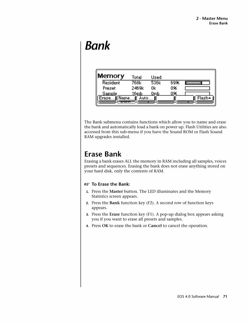
2 - Master MenuErase Bank
Bank
The Bank submenu contains functions which allow you to name and erase the bank and automatically load a bank on power up. Flash Utilities are also accessed from this sub-menu if you have the Sound ROM or Flash Sound RAM upgrades installed.
Erase BankErasing a bank erases ALL the memory in RAM including all samples, voices presets and sequences. Erasing the bank does not erase anything stored on your hard disk, only the contents of RAM.
v To Erase the Bank:
1. Press the Master button. The LED illuminates and the Memory Statistics screen appears.
2. Press the Bank function key (F2). A second row of function keys appears.
3. Press the Erase function key (F1). A pop-up dialog box appears asking you if you want to erase all presets and samples.
4. Press OK to erase the bank or Cancel to cancel the operation.
EOS 4.0 Software Manual 71
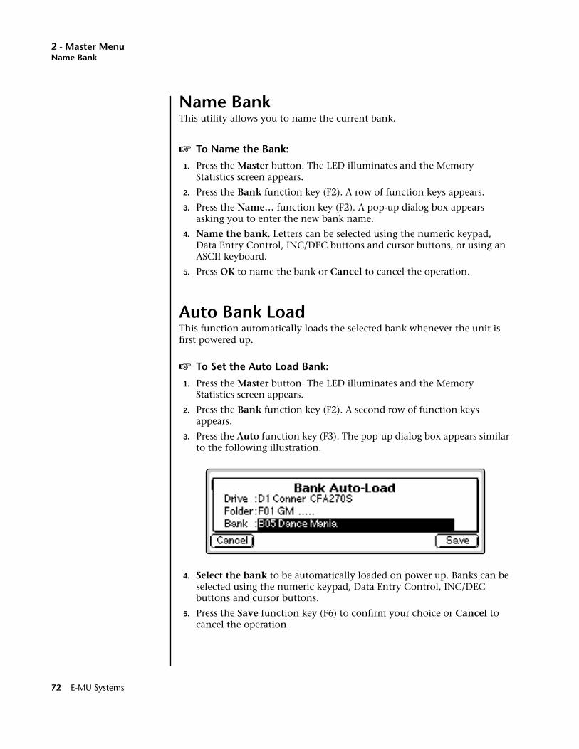
2 - Master MenuName Bank
Name BankThis utility allows you to name the current bank.
v To Name the Bank:
1. Press the Master button. The LED illuminates and the Memory Statistics screen appears.
2. Press the Bank function key (F2). A row of function keys appears.
3. Press the Name… function key (F2). A pop-up dialog box appears asking you to enter the new bank name.
4. Name the bank. Letters can be selected using the numeric keypad, Data Entry Control, INC/DEC buttons and cursor buttons, or using an ASCII keyboard.
5. Press OK to name the bank or Cancel to cancel the operation.
Auto Bank LoadThis function automatically loads the selected bank whenever the unit is first powered up.
v To Set the Auto Load Bank:
1. Press the Master button. The LED illuminates and the Memory Statistics screen appears.
2. Press the Bank function key (F2). A second row of function keys appears.
3. Press the Auto function key (F3). The pop-up dialog box appears similar to the following illustration.
4. Select the bank to be automatically loaded on power up. Banks can be selected using the numeric keypad, Data Entry Control, INC/DEC buttons and cursor buttons.
5. Press the Save function key (F6) to confirm your choice or Cancel to cancel the operation.
72 E-MU Systems

2 - Master MenuFlash Utilities
Flash UtilitiesThese special utilities are exclusively for use with Flash RAM. If you don't have Flash ROM or RAM installed in your Emulator, these options will not be available.
Preset RAM is used as the intermediary storage area when copying between Flash and disk. To copy presets from a floppy into Flash RAM, you first load them onto the bank, then use the Copy RAM➔Flash utility to copy them into Flash RAM.
• Clear Flash - Erases all resident presets and sequences.
• Compact Flash - Defragments Flash RAM. As presets are erased and modified, the memory can become fragmented. This utility re-orders the memory in the most efficient way.
• Copy RAM to Flash - Copies RAM presets into Flash RAM.
• Copy Flash to RAM - Copies Flash presets to Preset RAM.
v To Access the Flash Utilities:
1. Press the Master button. The LED illuminates and the Memory Statistics screen appears.
2. Press the Bank function key (F2). A second row of function keys appears.
3. Press the Flash function key (F6). Another row of function keys appears.
4. Select the desired Flash utility using function keys F1-F4. You will asked to confirm the selected operation.
5. Press OK (F6) to confirm your choice or Cancel (F1) to cancel the operation.
v To Copy Presets from Floppy to Flash:
1. Insert the Disk containing the presets into the floppy disk drive.
2. Press the Load function key (F4) on the main screen. The Load Preset screen appears.
3. Move the cursor up to the Drive Select field.
4. Select the Floppy drive using the Data Entry Control or INC/DEC buttons.
5. Press LoadAll (F6). The presets are loaded into RAM.
6. Press the Master button. The LED illuminates and the Memory Statistics screen appears.
7. Press the Bank function key (F2). A second row of function keys appears.
8. Press the Flash function key (F6). Another row of function keys appears.
EOS 4.0 Software Manual 73
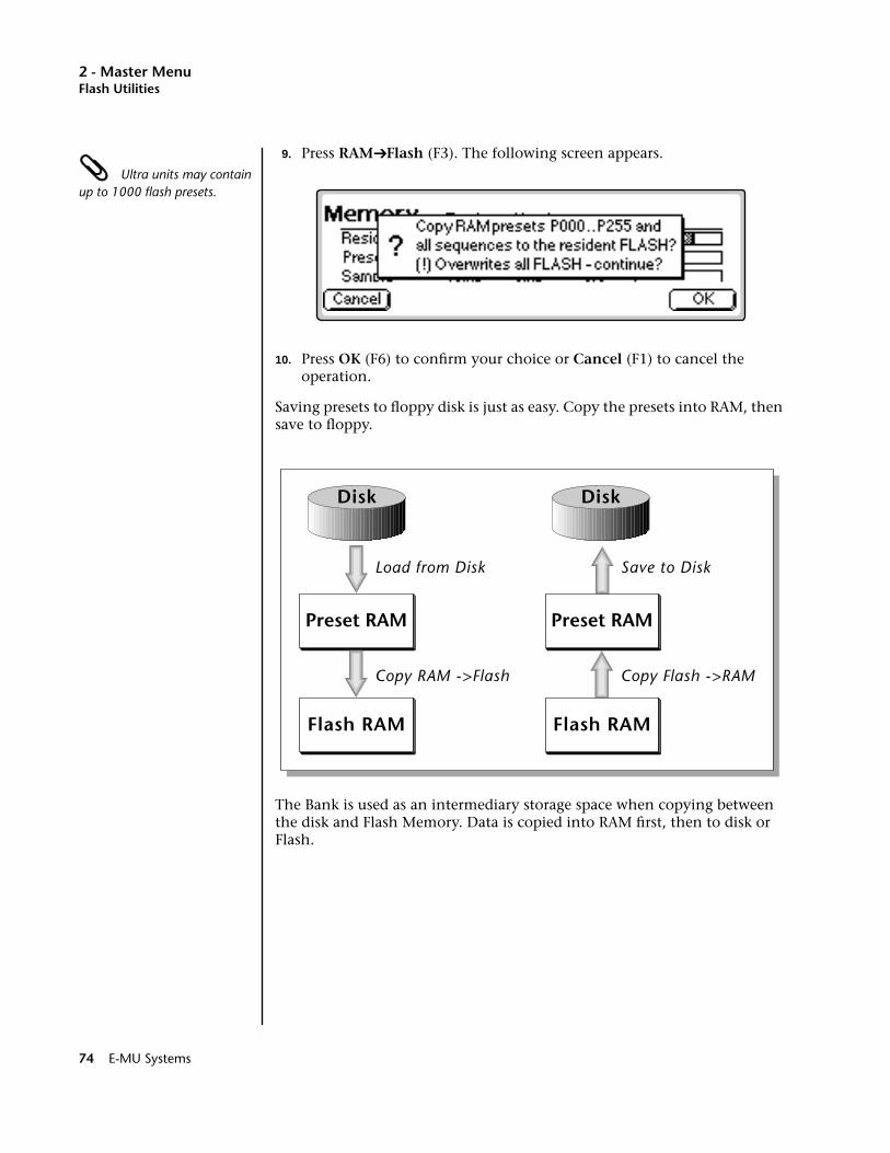
2 - Master MenuFlash Utilities
9. Press RAM➔Flash (F3). The following screen appears. Ultra units may contain up to 1000 flash presets.
10. Press OK (F6) to confirm your choice or Cancel (F1) to cancel the operation.
Saving presets to floppy disk is just as easy. Copy the presets into RAM, then save to floppy.
The Bank is used as an intermediary storage space when copying between the disk and Flash Memory. Data is copied into RAM first, then to disk or Flash.
Flash RAM
Preset RAM
Copy Flash ->RAM
Save to Disk
Flash RAM
Preset RAM
Disk Disk
Copy RAM ->Flash
Load from Disk
74 E-MU Systems

2 - Master MenuFlash Utilities
Using Sound Flash MemorySound Flash Memory is a similar to a hard disk containing one bank. A bank is assembled in Sample RAM, then Saved to Flash Memory. Individual presets cannot be saved to Flash Memory. The process of saving a bank to Flash is outlined below. Follow these instructions carefully.
v To Save a Bank to Flash Memory:
Erase the Bank1. Press Master.
2. Press Bank (F2).
3. Press Erase (F1).
Load the Bank you Wish to Save to Flash4. From the main screen, press the Arrow key, then Load.
5. Select the Drive, Folder and Bank you wish to Save, then press Load. The bank will load into RAM.
Save the Sounds to Flash6. Press the Arrow key, then Save.
7. Select Flash Memory as the drive you wish to Save to, then press OK (F6). The Samples will be stored in Flash Sound RAM.
Mount the Drive8. Press Disk.
9. Press Utils (F1).
10. Press Mount (F1).
Erase the Bank…again11. Press Master.
12. Press Bank (F2).
13. Press Erase (F1).
Erase Preset 000This operation deletes the empty preset in the P000 location of the bank so it won’t get merged into your Flash Bank. Unfortunately, you must have at least one preset in the bank, so before deleting P000 we’ll create a new empty preset at location 999.
14. Press Preset Manage.
15. Press New…
16. Select destination preset P999 Empty Preset.
EOS 4.0 Software Manual 75
2 - Master MenuFlash Utilities
17. Press OK, twice.
18. Select P000 Untitled Preset.
19. Press Utils (F1).
20. Press Erase Preset (F1). Press OK (F6).
Merge the PresetsThis operation merges the presets into the bank so that they will point to the correct locations in the Flash Sound Memory bank. The Emulator sees that the samples are in Flash Sound Memory and changes the sample numbers so they point to Flash.
21. From the main screen, press the Arrow key, then Load.
22. Select the Drive, Folder and Bank you wish to Save to Flash, then press Merge.
Save the PresetsNow that the sample numbers point to the samples in Flash Sound Memory, the presets can be written into CPU Flash memory using the Flash utilities.
23. Press Master.
24. Press Bank (F2).
25. Press Flash (F6).
26. Press RAM ->F (F3). A warning screen appears.
27. Press OK (F6). The presets will be written into CPU Flash memory.
v To Copy Flash RAM Presets to Disk:
Power up the machine and wait for it to finish booting.
1. Press Master.
2. Press Bank (F2).
3. Press Flash (F6).
4. Press F->RAM (F4). A warning screen appears advising you that you are about to overwrite RAM.
5. Press OK (F6) to write to RAM.
6. Press Master to return to the main screen
7. Insert the floppy disk into the drive if you wish to copy to floppy disk.
8. Press Save (F5). The popup Save window appears.
9. Select the destination Drive, Folder and Bank for the flash presets.
10. When the parameters are properly set, press OK (F6). A warning screen appears warning you that you are about to overwrite a bank.
11. Press OK (F6) to save the bank to Disk or Cancel (F1) to cancel the operation.
76 E-MU Systems
2 - Master MenuFlash Utilities
v To Copy Flash Sounds to Disk:
It might be a good idea to back-up the factory samples before you overwrite the Flash Bank with your own sounds.
1. Power up the machine and wait for it to finish booting.
2. From the main screen, press the Arrow key, then Load.
3. Wait for the bank to finish loading, then press the Arrow key, then Save.
4. Select the destination Drive, Folder and Bank for the flash presets.
5. When the parameters are properly set, press OK (F6).
EOS 4.0 Software Manual 77
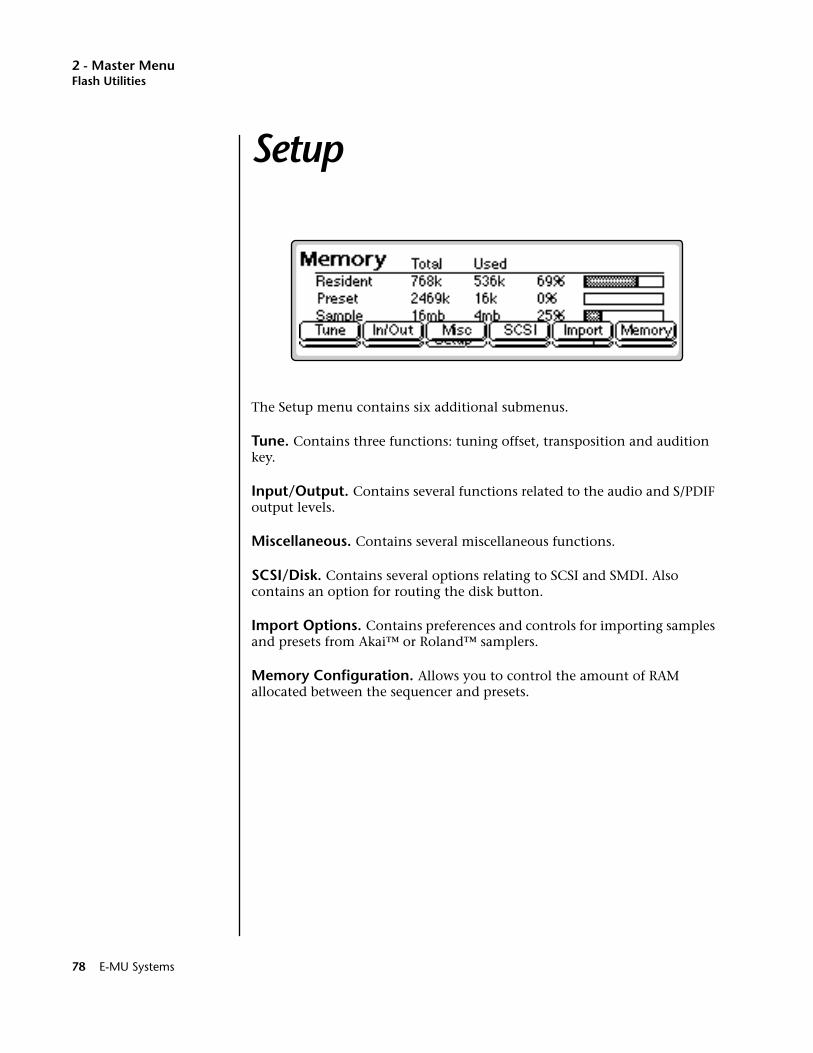
2 - Master MenuFlash Utilities
Setup
The Setup menu contains six additional submenus.
Tune. Contains three functions: tuning offset, transposition and audition key.
Input/Output. Contains several functions related to the audio and S/PDIF output levels.
Miscellaneous. Contains several miscellaneous functions.
SCSI/Disk. Contains several options relating to SCSI and SMDI. Also contains an option for routing the disk button.
Import Options. Contains preferences and controls for importing samples and presets from Akai™ or Roland™ samplers.
Memory Configuration. Allows you to control the amount of RAM allocated between the sequencer and presets.
78 E-MU Systems
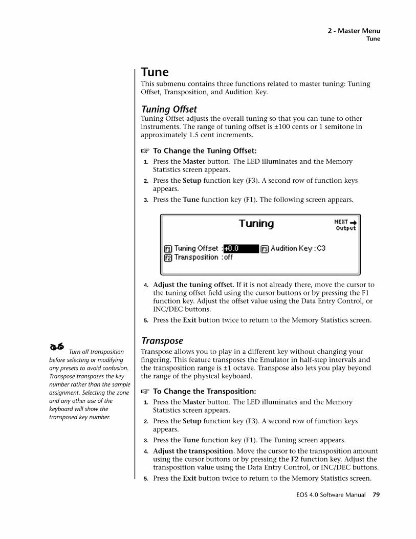
2 - Master MenuTune
TuneThis submenu contains three functions related to master tuning: Tuning Offset, Transposition, and Audition Key.
Tuning OffsetTuning Offset adjusts the overall tuning so that you can tune to other instruments. The range of tuning offset is ±100 cents or 1 semitone in approximately 1.5 cent increments.
v To Change the Tuning Offset:1. Press the Master button. The LED illuminates and the Memory
Statistics screen appears.
2. Press the Setup function key (F3). A second row of function keys appears.
3. Press the Tune function key (F1). The following screen appears.
4. Adjust the tuning offset. If it is not already there, move the cursor to the tuning offset field using the cursor buttons or by pressing the F1 function key. Adjust the offset value using the Data Entry Control, or INC/DEC buttons.
5. Press the Exit button twice to return to the Memory Statistics screen.
Transpose____ Turn off transposition before selecting or modifying any presets to avoid confusion. Transpose transposes the key number rather than the sample assignment. Selecting the zone and any other use of the keyboard will show the transposed key number.
Transpose allows you to play in a different key without changing your fingering. This feature transposes the Emulator in half-step intervals and the transposition range is ±1 octave. Transpose also lets you play beyond the range of the physical keyboard.
v To Change the Transposition:1. Press the Master button. The LED illuminates and the Memory
Statistics screen appears.
2. Press the Setup function key (F3). A second row of function keys appears.
3. Press the Tune function key (F1). The Tuning screen appears.
4. Adjust the transposition. Move the cursor to the transposition amount using the cursor buttons or by pressing the F2 function key. Adjust the transposition value using the Data Entry Control, or INC/DEC buttons.
5. Press the Exit button twice to return to the Memory Statistics screen.
EOS 4.0 Software Manual 79
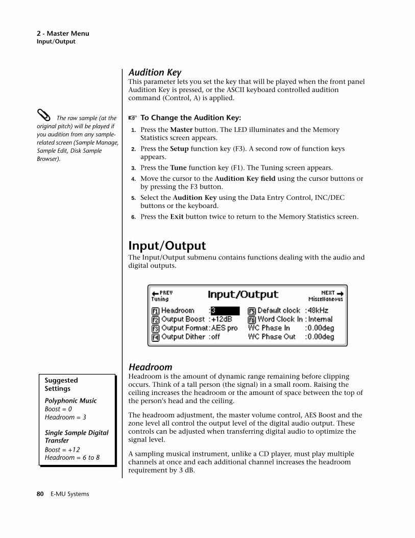
2 - Master MenuInput/Output
Audition KeyThis parameter lets you set the key that will be played when the front panel Audition Key is pressed, or the ASCII keyboard controlled audition command (Control, A) is applied.
The raw sample (at the original pitch) will be played if you audition from any sample-related screen (Sample Manage, Sample Edit, Disk Sample Browser).
v To Change the Audition Key:
1. Press the Master button. The LED illuminates and the Memory Statistics screen appears.
2. Press the Setup function key (F3). A second row of function keys appears.
3. Press the Tune function key (F1). The Tuning screen appears.
4. Move the cursor to the Audition Key field using the cursor buttons or by pressing the F3 button.
5. Select the Audition Key using the Data Entry Control, INC/DEC buttons or the keyboard.
6. Press the Exit button twice to return to the Memory Statistics screen.
Input/OutputThe Input/Output submenu contains functions dealing with the audio and digital outputs.
HeadroomHeadroom is the amount of dynamic range remaining before clipping occurs. Think of a tall person (the signal) in a small room. Raising the ceiling increases the headroom or the amount of space between the top of the person's head and the ceiling.
The headroom adjustment, the master volume control, AES Boost and the zone level all control the output level of the digital audio output. These controls can be adjusted when transferring digital audio to optimize the signal level.
A sampling musical instrument, unlike a CD player, must play multiple channels at once and each additional channel increases the headroom requirement by 3 dB.
SuggestedSettings
Polyphonic MusicBoost = 0Headroom = 3
Single Sample DigitalTransferBoost = +12Headroom = 6 to 8
80 E-MU Systems
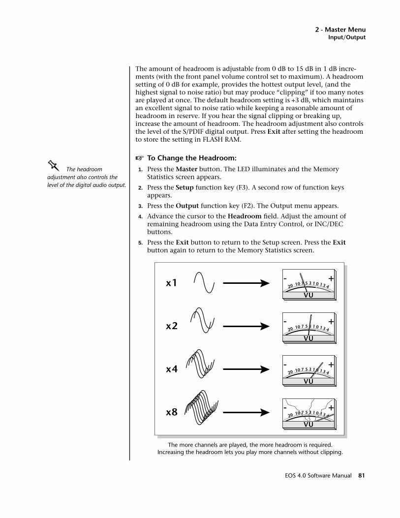
2 - Master MenuInput/Output
The amount of headroom is adjustable from 0 dB to 15 dB in 1 dB incre-ments (with the front panel volume control set to maximum). A headroom setting of 0 dB for example, provides the hottest output level, (and the highest signal to noise ratio) but may produce “clipping” if too many notes are played at once. The default headroom setting is +3 dB, which maintains an excellent signal to noise ratio while keeping a reasonable amount of headroom in reserve. If you hear the signal clipping or breaking up, increase the amount of headroom. The headroom adjustment also controls the level of the S/PDIF digital output. Press Exit after setting the headroom to store the setting in FLASH RAM.
v To Change the Headroom:
OOOO The headroom adjustment also controls the level of the digital audio output.
1. Press the Master button. The LED illuminates and the Memory Statistics screen appears.
2. Press the Setup function key (F3). A second row of function keys appears.
3. Press the Output function key (F2). The Output menu appears.
4. Advance the cursor to the Headroom field. Adjust the amount of remaining headroom using the Data Entry Control, or INC/DEC buttons.
5. Press the Exit button to return to the Setup screen. Press the Exit button again to return to the Memory Statistics screen.
The more channels are played, the more headroom is required. Increasing the headroom lets you play more channels without clipping.
x1
x4
x2
x8 0- +
13571020 1 3 4
VU
0- +
13571020 1 3 4
VU
0- +
13571020 1 3 4
VU
0- +
13571020 1 3 4
VU
EOS 4.0 Software Manual 81
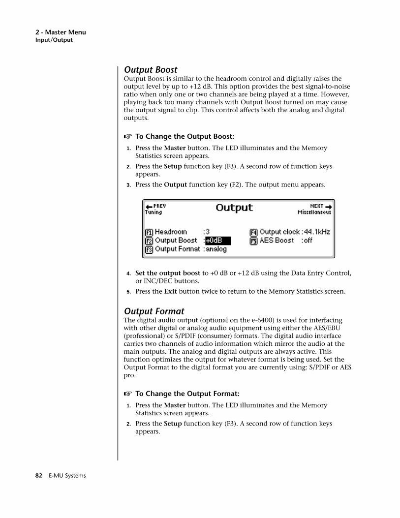
2 - Master MenuInput/Output
Output BoostOutput Boost is similar to the headroom control and digitally raises the output level by up to +12 dB. This option provides the best signal-to-noise ratio when only one or two channels are being played at a time. However, playing back too many channels with Output Boost turned on may cause the output signal to clip. This control affects both the analog and digital outputs.
v To Change the Output Boost:
1. Press the Master button. The LED illuminates and the Memory Statistics screen appears.
2. Press the Setup function key (F3). A second row of function keys appears.
3. Press the Output function key (F2). The output menu appears.
4. Set the output boost to +0 dB or +12 dB using the Data Entry Control, or INC/DEC buttons.
5. Press the Exit button twice to return to the Memory Statistics screen.
Output FormatThe digital audio output (optional on the e-6400) is used for interfacing with other digital or analog audio equipment using either the AES/EBU (professional) or S/PDIF (consumer) formats. The digital audio interface carries two channels of audio information which mirror the audio at the main outputs. The analog and digital outputs are always active. This function optimizes the output for whatever format is being used. Set the Output Format to the digital format you are currently using: S/PDIF or AES pro.
v To Change the Output Format:
1. Press the Master button. The LED illuminates and the Memory Statistics screen appears.
2. Press the Setup function key (F3). A second row of function keys appears.
82 E-MU Systems
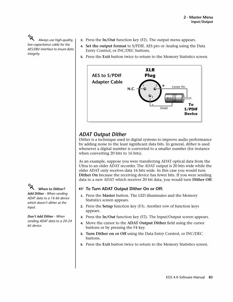
2 - Master MenuInput/Output
OOOO Always use high-quality, low-capacitance cable for the AES/EBU interface to insure data integrity.
3. Press the In/Out function key (F2). The output menu appears.
4. Set the output format to S/PDIF, AES pro or Analog using the Data Entry Control, or INC/DEC buttons.
5. Press the Exit button twice to return to the Memory Statistics screen.
ADAT Output DitherDither is a technique used in digital systems to improve audio performance by adding noise to the least significant data bits. In general, dither is used whenever a digital number is converted to a smaller number (for instance when converting 20 bits to 16 bits).
As an example, suppose you were transferring ADAT optical data from the Ultra to an older ADAT recorder. The ADAT output is 20 bits wide while the older ADAT only receives data 16 bits wide. In this case you would turn Dither On because the receiving device has fewer bits. If you were sending data to a new ADAT which receives 20 bit data, you would turn Dither Off.
OOOO When to Dither?Add Dither - When sending ADAT data to a 16 bit device which doesn’t dither at the input.
Don’t Add Dither - When sending ADAT data to a 20-24 bit device.
v To Turn ADAT Output Dither On or Off:
1. Press the Master button. The LED illuminates and the Memory Statistics screen appears.
2. Press the Setup function key (F3). Another row of function keys appears.
3. Press the In/Out function key (F2). The Input/Output screen appears.
4. Move the cursor to the ADAT Output Dither field using the cursor buttons or by pressing the F4 key.
5. Turn Dither on or Off using the Data Entry Control, or INC/DEC buttons.
6. Press the Exit button twice to return to the Memory Statistics screen.
1 2
3
-
N.C.
ToS/PDIFDevice
XLRPlug
+
Shield
Center Pin
RCA
AES to S/PDIFAdapter Cable
EOS 4.0 Software Manual 83
2 - Master MenuInput/Output
Default ClockUse the Default Clock to change the Emulator’s output sample rate (clock rate) to either 44.1 kHz or 48 kHz. This function sets the output rate of the entire machine (analog as well as digital outputs). Digital audio recorders automatically record at the clock rate of the source, so set this control at 48 kHz to record into a DAT recorder.
Ultra Series. This function is tied to analog sampling on the Ultra series Emulators. There are four analog sample rates (22.05 kHz, 24 kHz, 44.1 kHz, 48 kHz), but depending on this setting only two are selectable at a time.
Default clock = 44.1 kHz (22.05 kHz & 44.1 kHz)Default clock = 48 kHz (24 kHz & 48 kHz)
Change the default clock rate if the analog sample rate you want is not available in the Sample Manage module
v To Change the Default Clock Rate:
1. Press the Master button. The LED illuminates and the Memory Statistics screen appears.
2. Press the Setup function key (F3). Another row of function keys appears.
3. Press the In/Out function key (F2). The Input/Output screen appears.
4. Move the cursor to the Default clock field using the cursor buttons or by pressing the F4 key.
5. Set the Default clock rate using the Data Entry Control, or INC/DEC buttons.
6. Press the Exit button twice to return to the Memory Statistics screen.
84 E-MU Systems
2 - Master MenuInput/Output
Word Clock InThis Ultra function selects the Word Clock source. The Word Clock is the master time-base reference for the Emulator audio engine. Normally Word Clock In will be set to Internal to use the internal crystal-based reference. When transferring digital data, the different pieces of gear need to be synchronized to the same master clock. The BNC connector on the rear panel (optional on some models) allows the Emulator to synchronize with an external clock source (a house sync generator or word clock out from another piece of digital gear).
Note: If an external word clock is not physically connected, EOS defaults to its internal clock (even though the display is set to an external source).
• Internal .Uses the Emulator’s ultra-stable crystal reference oscillator.
• BNC........Uses the word clock received at the rear panel BNC Word Clock In connector.
• AES ........Uses the word clock provided by the rear panel AES digital input connector.
• ADAT .....Uses the Word Clock embedded in the ADAT optical data.
v To Set the Word Clock Source:
1. Press the Master button. The LED illuminates and the Memory Statistics screen appears.
2. Press the Setup function key (F3). Another row of function keys appears.
3. Press the In/Out function key (F2). The Input/Output screen appears.
4. Change the Word Clock In status. Move the cursor to Word Clock In using the cursor buttons or by pressing the F6 function key. Choose the Word Clock source using the Data Entry Control, or INC/DEC buttons.
5. Press the Exit button to return to the Memory Statistics screen.
WC Phase In/OutThis Ultra function allows you to adjust the phase relationship between input and output sample clocking in order to compensate for clock phase delays in other equipment or when word clock is daisy-chained. On EOS machines, a setting of 0.00 degrees means that the word clock in phase is exactly equal to the word clock out. If you are having trouble synchro-nizing to other equipment, try adjusting the appropriate word clock phase control to remedy the problem.
WC Phase In. Adjusts the phase relationship between the input clock (BNC, AES, or ADAT) and the digital output embedded data clock.
WC Phase Out. Adjusts the phase relationship between the input clock (BNC, AES, or ADAT) and the Emulator Word Clock output.
EOS 4.0 Software Manual 85

2 - Master MenuMiscellaneous
MiscellaneousThe Misc submenu, as the name suggests, contains master miscellaneous functions such as setting the LCD contrast, screen saver, and global preferences.
ContrastThis function changes the contrast of the front panel LCD so that it may be read easily from different angles. The contrast is adjustable from +7 to -8. Adjust the contrast for the most comfortable viewing.
v To Change the Contrast:1. Press the Master button. The LED illuminates and the Memory
Statistics screen appears.
2. Press the Setup function key (F3). A second row of function keys appears.
3. Press the Misc function key (F3). The Miscellaneous menu appears.
4. Move the cursor to the Contrast field using the cursor buttons or by pressing the F1 function key.
5. Adjust the Contrast using the Data Entry Control, or INC/DEC buttons.
6. Press the Exit button twice to return to the Memory Statistics screen.
Wrap Field Selection When wrap field selection is enabled, moving the cursor past the last selection in a window makes it automatically jump back up to the first selection. With wrap field selection Off, the cursor will NOT move past the last selection in a window. You have to use the up or left cursor button to go back.
v To Turn Wrap Field Selection On or Off:
1. Press the Master button. The LED illuminates and the Memory Statistics screen appears.
2. Press the Setup function key (F3). A second row of function keys appears.
3. Press the Misc function key (F3). The Miscellaneous menu appears.
4. Move the cursor to Wrap Field Selection using the cursor buttons or by pressing the F2 key.
86 E-MU Systems
2 - Master MenuMiscellaneous
5. Turn Wrap Field Selection On or Off using the Data Entry Control or INC/DEC buttons.
6. Press the Exit button twice to return to the Memory Statistics screen.
Screen SaverAfter a period of inactivity, the LCD backlight dims in order to prolong the life of the LCD. This parameter sets the period of time from 10 to 60 minutes (in increments of 10 minutes) before the screen dims, or “Never” so that the backlight always stays on. This option is not available on e64 or EIV units.
v To Turn the Screen Saver On or Off:
1. Press the Master button. The LED illuminates and the Memory Statistics screen appears.
2. Press the Setup function key (F3). A second row of function keys appears.
3. Press the Misc function key (F3). The miscellaneous menu appears.
4. Move the cursor to Screen Saver using the cursor buttons.
5. Set the screen saver time using the Data Entry Control, or INC/DEC buttons.
6. Press the Exit button to return to Memory Statistics.
Disable Sound ROMSample memory is user-expandable up to 64 megabytes with standard SIMM modules (up to 128 MB if ROM access is disabled). To use more than 64 MB of Sample Memory with the Sound ROM upgrade installed, you must turn off the Sound ROM. This screen is only accessible if you have Sound ROM SIMMs installed.
v To Disable the Sound ROM:
You only need to disable the Sound ROM access if you have Sound ROM and want to use more than 64 MB of Sample memory.
1. Press the Master button. The LED illuminates and the Memory Statistics screen appears.
2. Press the Setup function key (F3). A second row of function keys appears.
3. Press the Misc function key (F3). The Miscellaneous menu appears.
4. Move the cursor to Disable Sound ROM using the cursor buttons or by pressing the F4 function key.
5. Select Yes to disable the Sound ROM using the Data Entry Control, or INC/DEC buttons.
6. Press the Exit button twice to return to the Memory Statistics screen.
7. Reboot the system.
EOS 4.0 Software Manual 87
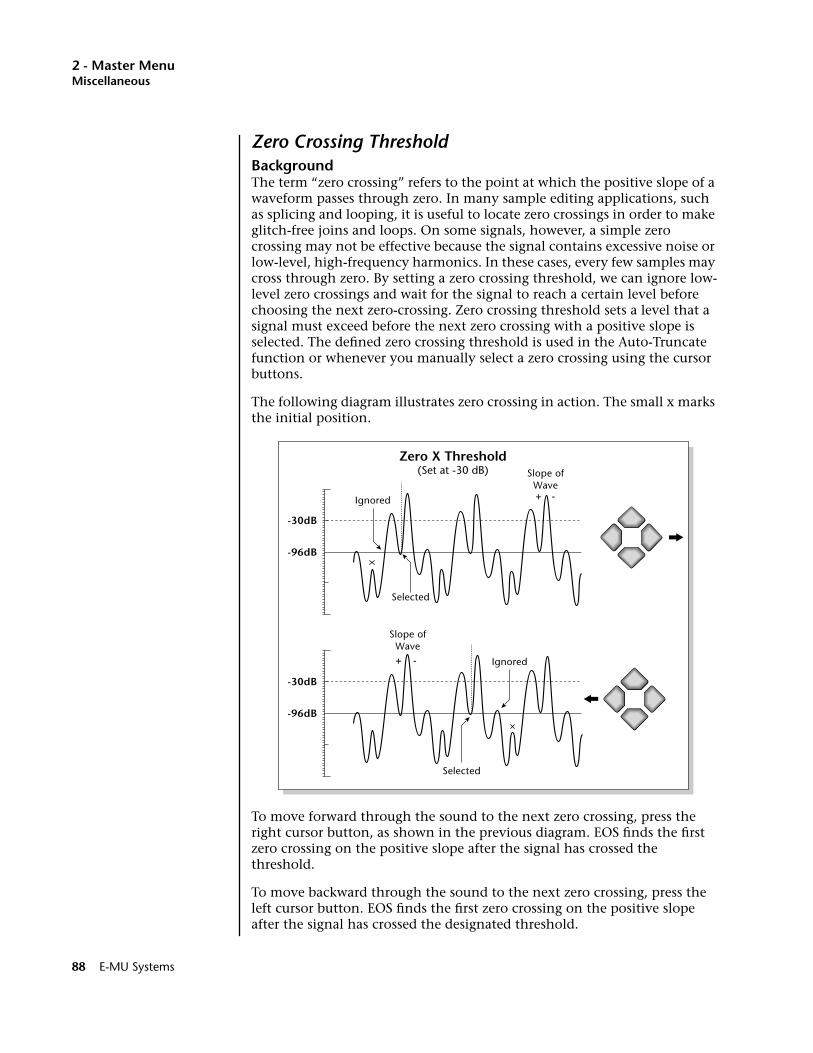
2 - Master MenuMiscellaneous
Zero Crossing ThresholdBackgroundThe term “zero crossing” refers to the point at which the positive slope of a waveform passes through zero. In many sample editing applications, such as splicing and looping, it is useful to locate zero crossings in order to make glitch-free joins and loops. On some signals, however, a simple zero crossing may not be effective because the signal contains excessive noise or low-level, high-frequency harmonics. In these cases, every few samples may cross through zero. By setting a zero crossing threshold, we can ignore low-level zero crossings and wait for the signal to reach a certain level before choosing the next zero-crossing. Zero crossing threshold sets a level that a signal must exceed before the next zero crossing with a positive slope is selected. The defined zero crossing threshold is used in the Auto-Truncate function or whenever you manually select a zero crossing using the cursor buttons.
The following diagram illustrates zero crossing in action. The small x marks the initial position.
To move forward through the sound to the next zero crossing, press the right cursor button, as shown in the previous diagram. EOS finds the first zero crossing on the positive slope after the signal has crossed the threshold.
To move backward through the sound to the next zero crossing, press the left cursor button. EOS finds the first zero crossing on the positive slope after the signal has crossed the designated threshold.
Selected
Selected
Zero X Threshold(Set at -30 dB)
Ignored
Ignored
-96dB
-30dB
Slope ofWave+ -
Slope ofWave+ -
-96dB
-30dB
88 E-MU Systems

2 - Master MenuUndo/Redo Enable
Use the Data Entry Control or INC/DEC buttons to select the zero crossing threshold. A setting of -96 dB will be the most sensitive; a setting of -30 dB will be the least sensitive. The selected zero crossing threshold is used in the auto-truncate function or whenever you manually select a zero crossing using the left/right cursor buttons. If auto truncate does not seem to be working well, try adjusting the zero crossing threshold.
v To Set the Zero-Crossing Threshold:1. Press the Master button. The LED illuminates and the Memory
Statistics screen appears.
2. Press the Setup function key (F3). A second row of function keys appears.
3. Press the Misc function key (F3). The Miscellaneous menu appears.
4. Move the cursor to Zero-X Threshold using the cursor buttons or by pressing the F5 function key.
5. Set the desired zero-crossing threshold using the Data Entry Control, or INC/DEC buttons.
6. Press the Exit button twice to return to the Memory Statistics screen.
Undo/Redo EnableOOOO Although the Undo/Redo feature lets you backtrack only one step, you can repeat the Undo and Redo commands an unlimited number of times.
During many Sample Editing operations, the sample being processed is backed-up automatically and stored on the system drive. If you do not like the results of the processing, with Undo enabled you can call up the Undo function and restore the original sample from the system drive. (Ah, if only life itself were so simple.) Best of all, the processed sample is backed-up also. Therefore, if you decide you liked the processed version better after all, you can actually undo the Undo (Redo).
If you are running low on disk drive space, the display will inform you if there is not enough memory to back up a sample onto the system drive. You then have two choices: either free up some additional memory by erasing banks on the system drive, or disable the Undo/Redo using this function.
v To Enable and Disable Undo/Redo:
____ If you are using a removable media hard disk and do not have a fixed hard disk connected, it is recommended that you turn Undo/Redo OFF.
1. Press the Master button. The LED illuminates and the Memory Statistics screen appears.
2. Press the Setup function key (F3). A second row of function keys appears.
3. Press the Misc function key (F3). The Miscellaneous menu appears.
4. Move the cursor to Undo/Redo Enable using the cursor buttons or the F6 function key.
5. Enable or disable Undo/Redo using the Data Entry Control, or INC/DEC buttons.
6. Press the Exit button twice to return to the Memory Statistics screen.
EOS 4.0 Software Manual 89

2 - Master MenuSCSI/Disk
SCSI/DiskEach Emulator has a SCSI device connector for attaching SCSI devices. You can have up to seven SCSI devices connected, or chained together. This chain is called a “bus.” Each device on the SCSI bus must have its own ID number. The SCSI/DISK submenu operations let you change the SCSI settings, including the SCSI ID of the Emulator, and program the function of the Disk button on the front panel of the unit.
SCSI IDThis utility allows you to change the SCSI ID number of the Emulator in the event that it conflicts with a device on the SCSI bus having the same ID number. For other units in the SCSI chain, refer to the manual that came with the hardware for instructions on how to change the SCSI ID.
OOOO The SCSI ID of a device does not necessarily indicate the physical location of the device on the SCSI bus. For example, your Emulator can be the last item of three in the chain and have a SCSI ID of 2.
v To Change the ID Number:
1. Press the Master button. The LED illuminates and the Memory Statistics screen appears.
2. Press the Setup function key (F3). A second row of function keys appears.
3. Press the SCSI/Disk function key (F4). The SCSI/Disk menu appears.
4. Move the cursor to the SCSI ID number using the cursor buttons or by pressing the F1 function key.
5. Select the ID number using the Data Entry Control, or INC/DEC buttons.
6. Press the Exit button twice to return to the Memory Statistics screen.
90 E-MU Systems

2 - Master MenuSCSI/Disk
SCSI Termination On/OffBoth ends of a SCSI chain (meaning the first and last device on the bus) must be terminated for proper operation. If not properly terminated, the equipment can malfunction. Some equipment will not work at all if the chain is not properly terminated. Proper termination helps reduce line echoes or standing waves on the SCSI bus. This utility turns the SCSI termi-nation on and off internal under software control. SCSI termination should usually be left on since the Emulator is normally connected at one end of the SCSI line.
v To Turn SCSI Termination On or Off:
1. Press the Master button. The LED illuminates and the Memory Statistics screen appears.
2. Press the Setup function key (F3). A second row of function keys appears.
3. Press the SCSI/Disk function key (F4). The SCSI/Disk menu appears.
4. Move the cursor to the SCSI Termination field using the cursor buttons or by pressing the F2 function key.
5. Turn SCSI Termination On or Off using the Data Entry Control, or INC/DEC buttons.
6. Press the Exit button to return to the Memory Statistics screen.
Avoid Host on IDOOOO This function tells EOS to avoid any host on the selected SCSI ID number. All Macs use ID 7. If you're a PC user, make sure this number matches your SCSI card.
SCSI was originally designed to have only one Master on the bus. EOS contains special software which lets multiple “Master” devices coexist peacefully on the SCSI bus. If you have a computer connected to the SCSI bus set this ID number so it matches your computer’s SCSI card.
v To Enable a Computer on the SCSI Bus:
1. Find out the SCSI ID of your computer’s SCSI card. The Macintosh is set to ID #7. PCs use various SCSI ID numbers.
2. Press the Master button. The LED illuminates and the Memory Statistics screen appears.
3. Press the Setup function key (F3). A second row of function keys appears.
4. Press the SCSI/Disk function key (F4). The SCSI/Disk menu appears.
5. Move the cursor to “Avoid Host on ID” or press F4.
6. Set the ID number to avoid using the Data Entry Control, or INC/DEC buttons.
7. Press the Exit button to return to the Memory Statistics screen.
EOS 4.0 Software Manual 91
2 - Master MenuSCSI/Disk
Disk Button Goes To:This parameter lets you to set the function of the front panel disk button. The disk button can be set to jump directly into SoundSprint mode or it can call up the last Disk Browser screen you accessed.
v To Assign the Disk Button:
1. Press the Master button. The LED illuminates and the Memory Statistics screen appears.
2. Press the Setup function key (F3). A second row of function keys appears.
3. Press the SCSI/Disk function key (F4). The SCSI/Disk menu appears.
4. Move the cursor to the “Disk Button goes to” field using the cursor buttons or by pressing the F5 function key.
5. Select Sprint or Last using the Data Entry Control, or INC/DEC buttons.
6. Press the Exit button to return to the Memory Statistics screen.
92 E-MU Systems
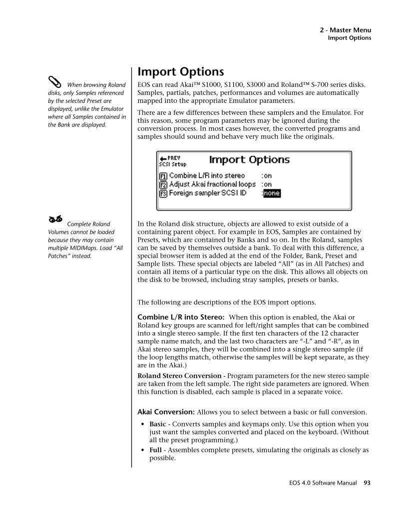
2 - Master MenuImport Options
Import Options When browsing Roland disks, only Samples referenced by the selected Preset are displayed, unlike the Emulator where all Samples contained in the Bank are displayed.
EOS can read Akai™ S1000, S1100, S3000 and Roland™ S-700 series disks. Samples, partials, patches, performances and volumes are automatically mapped into the appropriate Emulator parameters.
There are a few differences between these samplers and the Emulator. For this reason, some program parameters may be ignored during the conversion process. In most cases however, the converted programs and samples should sound and behave very much like the originals.
____ Complete Roland Volumes cannot be loaded because they may contain multiple MIDIMaps. Load “All Patches” instead.
In the Roland disk structure, objects are allowed to exist outside of a containing parent object. For example in EOS, Samples are contained by Presets, which are contained by Banks and so on. In the Roland, samples can be saved by themselves outside a bank. To deal with this difference, a special browser item is added at the end of the Folder, Bank, Preset and Sample lists. These special objects are labeled “All” (as in All Patches) and contain all items of a particular type on the disk. This allows all objects on the disk to be browsed, including stray samples, presets or banks.
The following are descriptions of the EOS import options.
Combine L/R into Stereo: When this option is enabled, the Akai or Roland key groups are scanned for left/right samples that can be combined into a single stereo sample. If the first ten characters of the 12 character sample name match, and the last two characters are “-L” and “-R”, as in Akai stereo samples, they will be combined into a single stereo sample (if the loop lengths match, otherwise the samples will be kept separate, as they are in the Akai.)
Roland Stereo Conversion - Program parameters for the new stereo sample are taken from the left sample. The right side parameters are ignored. When this function is disabled, each sample is placed in a separate voice.
Akai Conversion: Allows you to select between a basic or full conversion.
• Basic - Converts samples and keymaps only. Use this option when you just want the samples converted and placed on the keyboard. (Without all the preset programming.)
• Full - Assembles complete presets, simulating the originals as closely as possible.
EOS 4.0 Software Manual 93

2 - Master MenuImport Options
Adjust Fractional Loops: The Akai S1000 implements sample looping differently than the Emulator. Because of this difference, some loops may “tick” slightly or appear out of tune after being transferred from the Akai. This function automatically repairs any incorrect sample loops after being transferred. Be advised that the transfer may take slightly longer (up to 15% more time) with Adjust Fractional Loops turned enabled.
Foreign Sampler SCSI ID: If you have a brand of sampler other than the Akai or Roland connected to the SCSI bus, EOS needs to know its SCSI ID in order to avoid SCSI conflicts. The Foreign SCSI ID should be entered before physically connecting the sampler onto the SCSI chain. You do NOT have to set this parameter for Akai or Roland formatted storage devices. EOS recognizes them automatically.
v To Set the Import Options:
Limitations for Roland Imports• Supports 512 byte/sector devices only.• Translates tuning, keymap, velocity switching and positional crossfade only. No envelopes, modulation filter settings cords, etc.• Imports only one forward loop.
1. Press the Master button. The LED illuminates and the Memory Statistics screen appears.
2. Press the Setup function key (F3). A second row of function keys appears.
3. Press the Import function key (F4). The Import Options menu appears.
4. Move the cursor to the desired option using the cursor buttons and change the parameter using the Data Entry Control or the INC/DEC buttons.
5. Press the Exit button twice to return to the Memory Statistics screen.
94 E-MU Systems
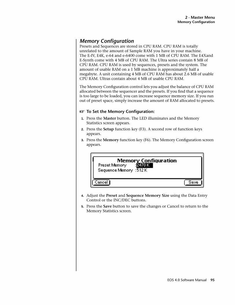
2 - Master MenuMemory Configuration
Memory ConfigurationPresets and Sequences are stored in CPU RAM. CPU RAM is totally unrelated to the amount of Sample RAM you have in your machine. The E-IV, E4K, e-64 and e-6400 come with 1 MB of CPU RAM. The E4Xand E-Synth come with 4 MB of CPU RAM. The Ultra series contain 8 MB of CPU RAM. CPU RAM is used by sequences, presets and the system. The amount of usable RAM on a 1 MB machine is approximately half a megabyte. A unit containing 4 MB of CPU RAM has about 2.6 MB of usable CPU RAM. Ultras contain about 4 MB of usable CPU RAM.
The Memory Configuration control lets you adjust the balance of CPU RAM allocated between the sequencer and the presets. If you find that a sequence is too large to be loaded, you can increase sequence memory size. If you run out of preset space, simply increase the amount of RAM allocated to presets.
v To Set the Memory Configuration:
1. Press the Master button. The LED illuminates and the Memory Statistics screen appears.
2. Press the Setup function key (F3). A second row of function keys appears.
3. Press the Memory function key (F6). The Memory Configuration screen appears.
4. Adjust the Preset and Sequence Memory Size using the Data Entry Control or the INC/DEC buttons.
5. Press the Save button to save the changes or Cancel to return to the Memory Statistics screen.
EOS 4.0 Software Manual 95
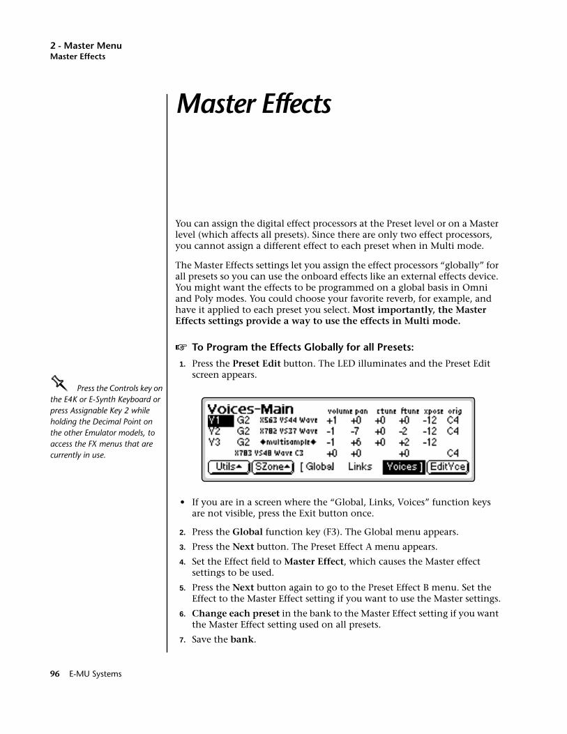
2 - Master MenuMaster Effects
Master Effects
You can assign the digital effect processors at the Preset level or on a Master level (which affects all presets). Since there are only two effect processors, you cannot assign a different effect to each preset when in Multi mode.
The Master Effects settings let you assign the effect processors “globally” for all presets so you can use the onboard effects like an external effects device. You might want the effects to be programmed on a global basis in Omni and Poly modes. You could choose your favorite reverb, for example, and have it applied to each preset you select. Most importantly, the Master Effects settings provide a way to use the effects in Multi mode.
v To Program the Effects Globally for all Presets:
1. Press the Preset Edit button. The LED illuminates and the Preset Edit screen appears.
OOOO Press the Controls key on the E4K or E-Synth Keyboard or press Assignable Key 2 while holding the Decimal Point on the other Emulator models, to access the FX menus that are currently in use.
• If you are in a screen where the “Global, Links, Voices” function keys are not visible, press the Exit button once.
2. Press the Global function key (F3). The Global menu appears.
3. Press the Next button. The Preset Effect A menu appears.
4. Set the Effect field to Master Effect, which causes the Master effect settings to be used.
5. Press the Next button again to go to the Preset Effect B menu. Set the Effect to the Master Effect setting if you want to use the Master settings.
6. Change each preset in the bank to the Master Effect setting if you want the Master Effect setting used on all presets.
7. Save the bank.
96 E-MU Systems
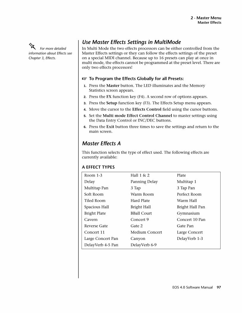
2 - Master MenuMaster Effects
Use Master Effects Settings in MultiModeOOOO For more detailed information about Effects see Chapter 3, Effects.
In Multi Mode the two effects processors can be either controlled from the Master Effects settings or they can follow the effects settings of the preset on a special MIDI channel. Because up to 16 presets can play at once in multi mode, the effects cannot be programmed at the preset level. There are only two effects processors!
v To Program the Effects Globally for all Presets:
1. Press the Master button. The LED illuminates and the Memory Statistics screen appears.
2. Press the FX function key (F4). A second row of options appears.
3. Press the Setup function key (F3). The Effects Setup menu appears.
4. Move the cursor to the Effects Control field using the cursor buttons.
5. Set the Multi mode Effect Control Channel to master settings using the Data Entry Control or INC/DEC buttons.
6. Press the Exit button three times to save the settings and return to the main screen.
Master Effects A
This function selects the type of effect used. The following effects are currently available:
A EFFECT TYPES
Room 1-3 Hall 1 & 2 Plate
Delay Panning Delay Multitap 1
Multitap Pan 3 Tap 3 Tap Pan
Soft Room Warm Room Perfect Room
Tiled Room Hard Plate Warm Hall
Spacious Hall Bright Hall Bright Hall Pan
Bright Plate BBall Court Gymnasium
Cavern Concert 9 Concert 10 Pan
Reverse Gate Gate 2 Gate Pan
Concert 11 Medium Concert Large Concert
Large Concert Pan Canyon DelayVerb 1-3
DelayVerb 4-5 Pan DelayVerb 6-9
EOS 4.0 Software Manual 97
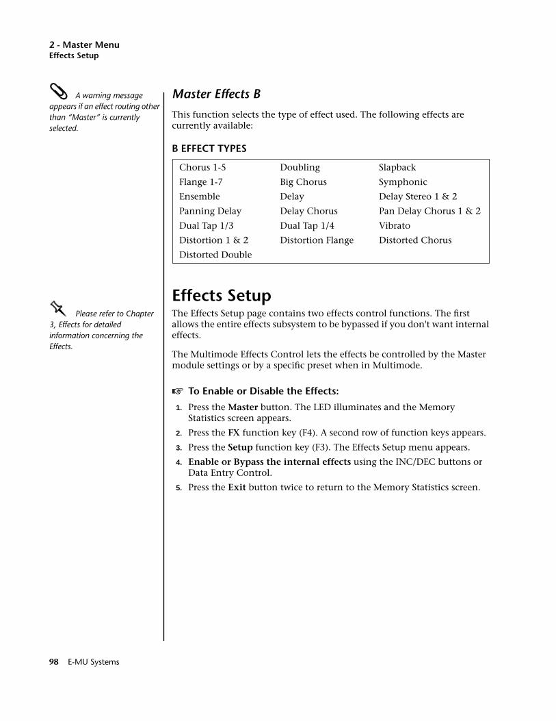
2 - Master MenuEffects Setup
A warning message appears if an effect routing other than “Master” is currently selected.
Master Effects B
This function selects the type of effect used. The following effects are currently available:
B EFFECT TYPES
Effects SetupOOOO Please refer to Chapter 3, Effects for detailed information concerning the Effects.
The Effects Setup page contains two effects control functions. The first allows the entire effects subsystem to be bypassed if you don't want internal effects.
The Multimode Effects Control lets the effects be controlled by the Master module settings or by a specific preset when in Multimode.
v To Enable or Disable the Effects:
1. Press the Master button. The LED illuminates and the Memory Statistics screen appears.
2. Press the FX function key (F4). A second row of function keys appears.
3. Press the Setup function key (F3). The Effects Setup menu appears.
4. Enable or Bypass the internal effects using the INC/DEC buttons or Data Entry Control.
5. Press the Exit button twice to return to the Memory Statistics screen.
Chorus 1-5 Doubling Slapback
Flange 1-7 Big Chorus Symphonic
Ensemble Delay Delay Stereo 1 & 2
Panning Delay Delay Chorus Pan Delay Chorus 1 & 2
Dual Tap 1/3 Dual Tap 1/4 Vibrato
Distortion 1 & 2 Distortion Flange Distorted Chorus
Distorted Double
98 E-MU Systems
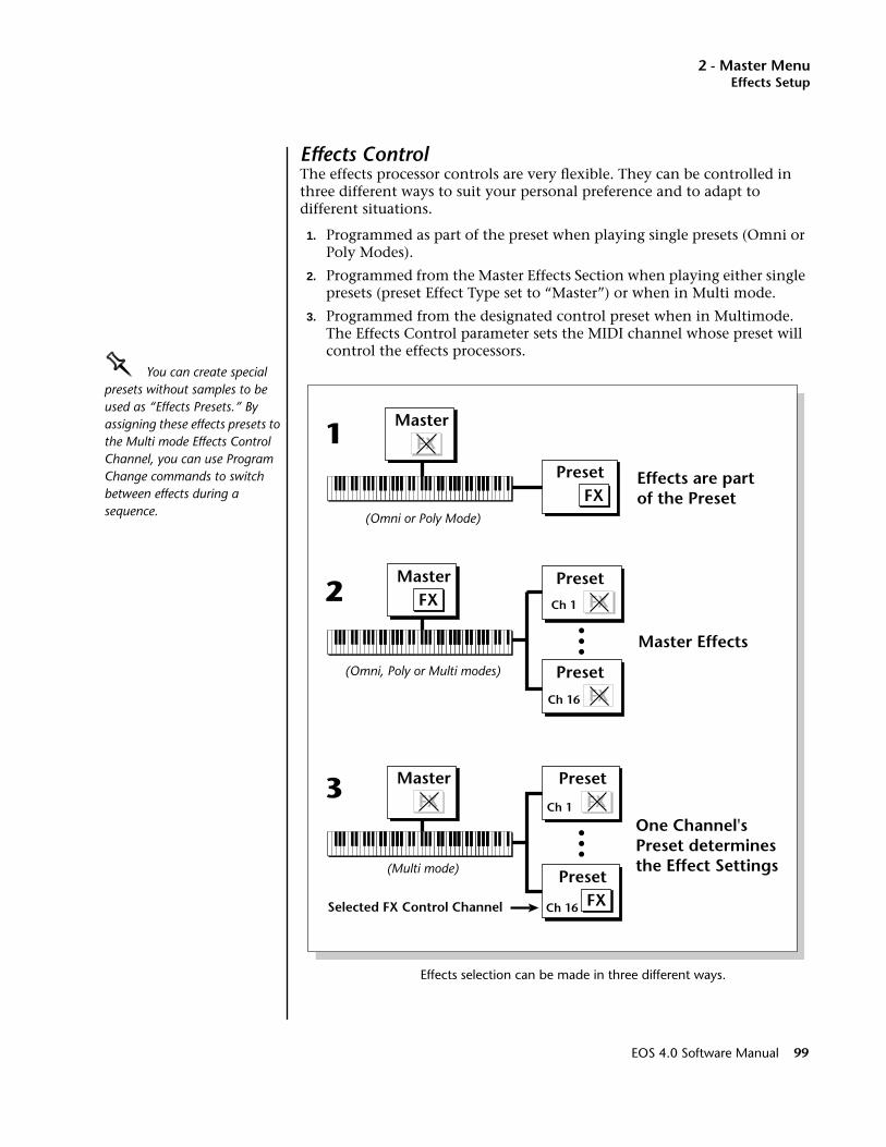
2 - Master MenuEffects Setup
Effects ControlThe effects processor controls are very flexible. They can be controlled in three different ways to suit your personal preference and to adapt to different situations.
1. Programmed as part of the preset when playing single presets (Omni or Poly Modes).
2. Programmed from the Master Effects Section when playing either single presets (preset Effect Type set to “Master”) or when in Multi mode.
3. Programmed from the designated control preset when in Multimode. The Effects Control parameter sets the MIDI channel whose preset will control the effects processors.
OOOO You can create special presets without samples to be used as “Effects Presets.” By assigning these effects presets to the Multi mode Effects Control Channel, you can use Program Change commands to switch between effects during a sequence.
Effects selection can be made in three different ways.
PresetFX
MasterFX
Effects are partof the Preset
1
(Omni or Poly Mode)
MasterFX
Preset
Ch 16 FX
Master Effects
PresetFXCh 1
2
(Omni, Poly or Multi modes)
PresetFX
Preset
FX
FX
Master
Ch 16
Ch 1
Selected FX Control Channel
One Channel'sPreset determinesthe Effect Settings
3
(Multi mode)
EOS 4.0 Software Manual 99
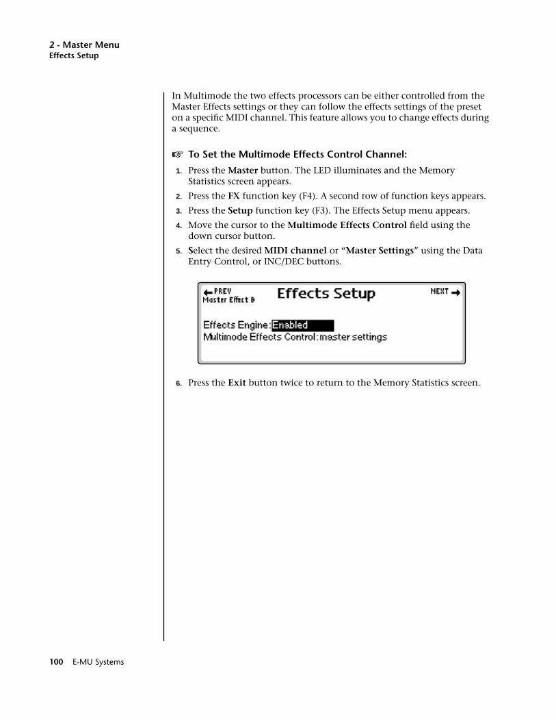
2 - Master MenuEffects Setup
In Multimode the two effects processors can be either controlled from the Master Effects settings or they can follow the effects settings of the preset on a specific MIDI channel. This feature allows you to change effects during a sequence.
v To Set the Multimode Effects Control Channel:
1. Press the Master button. The LED illuminates and the Memory Statistics screen appears.
2. Press the FX function key (F4). A second row of function keys appears.
3. Press the Setup function key (F3). The Effects Setup menu appears.
4. Move the cursor to the Multimode Effects Control field using the down cursor button.
5. Select the desired MIDI channel or “Master Settings” using the Data Entry Control, or INC/DEC buttons.
6. Press the Exit button twice to return to the Memory Statistics screen.
100 E-MU Systems
2 - Master MenuSequence Manage
Sequence Manage
EOS version 4 contains a powerful 48-track onboard sequencer, always available to capture your musical ideas. The sequencer's easy to use interface lets you lay down tracks almost as fast as you can play them. Please refer to Chapter 4, Sequencer for detailed information on the sequencer.
The Sequence Manage menu displays the memory used and the number of tracks in the current sequence and contains the following functions:
Utilities. Contains Erase and Copy commands.
Name. Allows you to name your sequences.
Export. Exports the currently selected sequence as a Standard MIDI File.
Loop. Sets the sequence to play continuously or to stop playing once it reaches the end.
Edit. The Edit function key toggles between the main sequencer functions and the sequence editor functions.
Menu/Transport. Toggles between the Sequence Manager functions and the Transport Control keys.
EOS 4.0 Software Manual 101
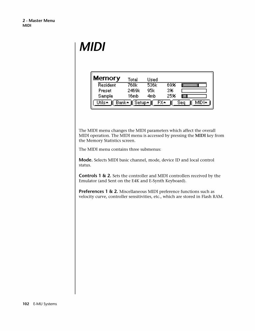
2 - Master MenuMIDI
MIDI
The MIDI menu changes the MIDI parameters which affect the overall MIDI operation. The MIDI menu is accessed by pressing the MIDI key from the Memory Statistics screen.
The MIDI menu contains three submenus:
Mode. Selects MIDI basic channel, mode, device ID and local control status.
Controls 1 & 2. Sets the controller and MIDI controllers received by the Emulator (and Sent on the E4K and E-Synth Keyboard).
Preferences 1 & 2. Miscellaneous MIDI preference functions such as velocity curve, controller sensitivities, etc., which are stored in Flash RAM.
102 E-MU Systems
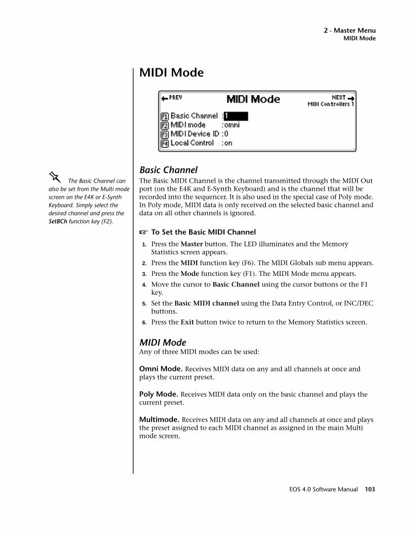
2 - Master MenuMIDI Mode
MIDI Mode
Basic ChannelOOOO The Basic Channel can also be set from the Multi mode screen on the E4K or E-Synth Keyboard. Simply select the desired channel and press the SetBCh function key (F2).
The Basic MIDI Channel is the channel transmitted through the MIDI Out port (on the E4K and E-Synth Keyboard) and is the channel that will be recorded into the sequencer. It is also used in the special case of Poly mode. In Poly mode, MIDI data is only received on the selected basic channel and data on all other channels is ignored.
v To Set the Basic MIDI Channel
1. Press the Master button. The LED illuminates and the Memory Statistics screen appears.
2. Press the MIDI function key (F6). The MIDI Globals sub menu appears.
3. Press the Mode function key (F1). The MIDI Mode menu appears.
4. Move the cursor to Basic Channel using the cursor buttons or the F1 key.
5. Set the Basic MIDI channel using the Data Entry Control, or INC/DEC buttons.
6. Press the Exit button twice to return to the Memory Statistics screen.
MIDI ModeAny of three MIDI modes can be used:
Omni Mode. Receives MIDI data on any and all channels at once and plays the current preset.
Poly Mode. Receives MIDI data only on the basic channel and plays the current preset.
Multimode. Receives MIDI data on any and all channels at once and plays the preset assigned to each MIDI channel as assigned in the main Multi mode screen.
EOS 4.0 Software Manual 103
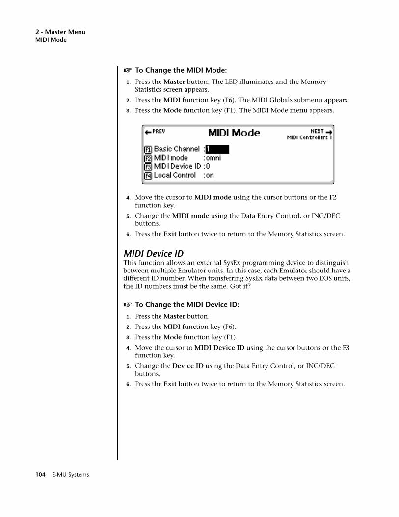
2 - Master MenuMIDI Mode
v To Change the MIDI Mode:
1. Press the Master button. The LED illuminates and the Memory Statistics screen appears.
2. Press the MIDI function key (F6). The MIDI Globals submenu appears.
3. Press the Mode function key (F1). The MIDI Mode menu appears.
4. Move the cursor to MIDI mode using the cursor buttons or the F2 function key.
5. Change the MIDI mode using the Data Entry Control, or INC/DEC buttons.
6. Press the Exit button twice to return to the Memory Statistics screen.
MIDI Device IDThis function allows an external SysEx programming device to distinguish between multiple Emulator units. In this case, each Emulator should have a different ID number. When transferring SysEx data between two EOS units, the ID numbers must be the same. Got it?
v To Change the MIDI Device ID:
1. Press the Master button.
2. Press the MIDI function key (F6).
3. Press the Mode function key (F1).
4. Move the cursor to MIDI Device ID using the cursor buttons or the F3 function key.
5. Change the Device ID using the Data Entry Control, or INC/DEC buttons.
6. Press the Exit button twice to return to the Memory Statistics screen.
104 E-MU Systems
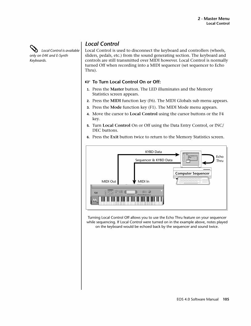
2 - Master MenuLocal Control
Local Control Local Control is available only on E4K and E-Synth Keyboards.
Local Control is used to disconnect the keyboard and controllers (wheels, sliders, pedals, etc.) from the sound generating section. The keyboard and controls are still transmitted over MIDI however. Local Control is normally turned Off when recording into a MIDI sequencer (set sequencer to Echo Thru).
v To Turn Local Control On or Off:
1. Press the Master button. The LED illuminates and the Memory Statistics screen appears.
2. Press the MIDI function key (F6). The MIDI Globals sub menu appears.
3. Press the Mode function key (F1). The MIDI Mode menu appears.
4. Move the cursor to Local Control using the cursor buttons or the F4 key.
5. Turn Local Control On or Off using the Data Entry Control, or INC/DEC buttons.
6. Press the Exit button twice to return to the Memory Statistics screen.
Turning Local Control Off allows you to use the Echo Thru feature on your sequencer while sequencing. If Local Control were turned on in the example above, notes played
on the keyboard would be echoed back by the sequencer and sound twice.
Computer Sequencer
SAMPLING SYNTHESIS CONTROLLER
EMULATOR
P R E S E T
S A M P L E
S E Q U E N C E R
P A G E
L E V E L
P R E S E T S E L E C T
R E A L T I M E C O N T R O L L E R SA S S I G N A B L E K E Y S
E N T E RE X I T
R E T U R N
.
EchoThru
KYBD Data
Sequencer & KYBD Data
MIDI InMIDI Out
EOS 4.0 Software Manual 105
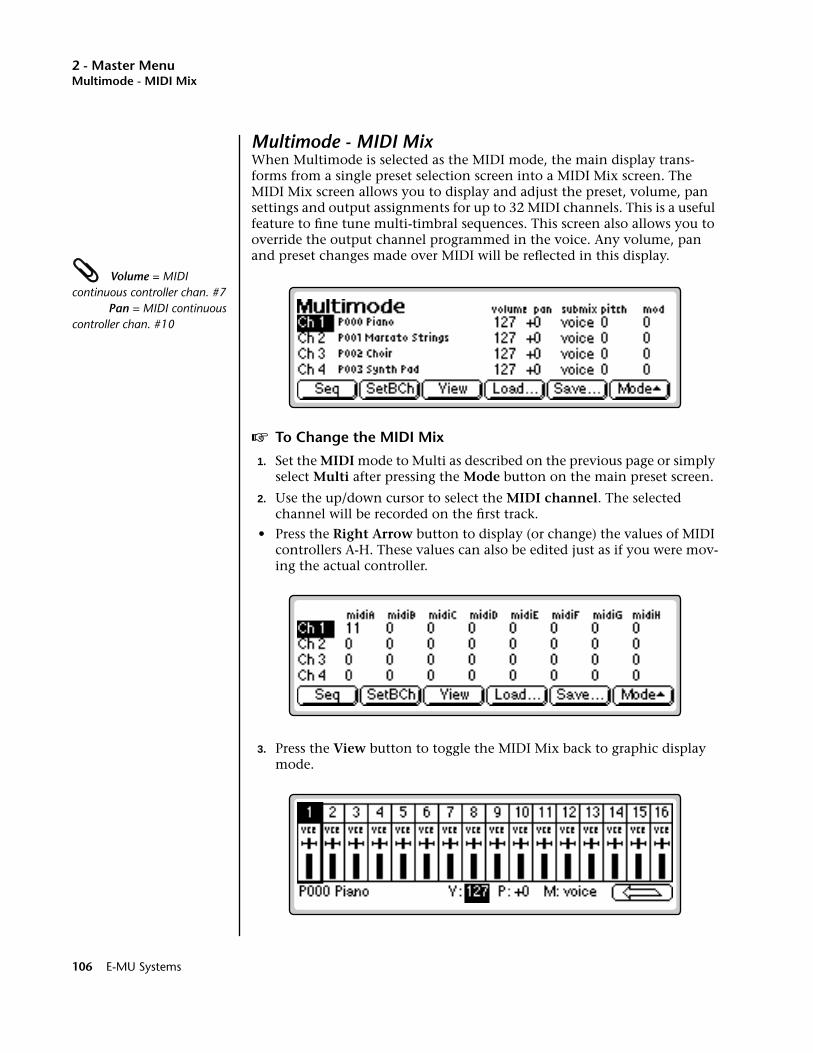
2 - Master MenuMultimode - MIDI Mix
Multimode - MIDI MixWhen Multimode is selected as the MIDI mode, the main display trans-forms from a single preset selection screen into a MIDI Mix screen. The MIDI Mix screen allows you to display and adjust the preset, volume, pan settings and output assignments for up to 32 MIDI channels. This is a useful feature to fine tune multi-timbral sequences. This screen also allows you to override the output channel programmed in the voice. Any volume, pan and preset changes made over MIDI will be reflected in this display.
Volume = MIDI continuous controller chan. #7 Pan = MIDI continuous controller chan. #10
v To Change the MIDI Mix
1. Set the MIDI mode to Multi as described on the previous page or simply select Multi after pressing the Mode button on the main preset screen.
2. Use the up/down cursor to select the MIDI channel. The selected channel will be recorded on the first track.
• Press the Right Arrow button to display (or change) the values of MIDI controllers A-H. These values can also be edited just as if you were mov-ing the actual controller.
3. Press the View button to toggle the MIDI Mix back to graphic display mode.
106 E-MU Systems

2 - Master MenuMultimode - MIDI Mix
4. Select the desired MIDI channel using the up/down cursor buttons.
Pan ADDS to the pan setting made in the voice and is not an absolute pan setting.
5. Select preset, volume, pan or the output channel using the left/right cursor buttons. Change the parameter values using the Data Entry Control, the INC/DEC buttons, or the numeric keypad.
6. Set the keyboard mode to "whole" to change the main screen back to a single preset display format.
7. Press the left arrow function key (F6) and then the View function key to change the display to list view mode.
The list view screen displays the values of the pitch and modulation wheels. The amounts of the wheels can also be adjusted, just as if you were moving the wheels to the left of the keyboard.
v If you have an Ultra or a MIDI Channel Expander Card Installed:
1. Press the Next key to view the additional MIDI channels. The diagram below shows how the MIDI channels on the expander port correspond to internal channels.
To Change Program Banks via MIDI, send:1) Continuous Controller 00 = 0 2) Cont. Controller 32 = Bank # 3) Program Change
This allows you to access presets higher than 128 via MIDI.
On your sequencer: Use Continuous Controller #32
Chan 1
Chan 2
Chan 3
Chan 4
Chan 5
Chan 6
Chan 7
Chan 8
Chan 17
Chan 18
Chan 19
Chan 20
Chan 21
Chan 22
Chan 23
Chan 24
Incoming Internal
Chan 9
Chan 10
Chan 11
Chan 12
Chan 13
Chan 14
Chan 15
Chan 16
Chan 25
Chan 26
Chan 27
Chan 28
Chan 29
Chan 30
Chan 31
Chan 32
Incoming Internal
Up
Down
Left Right
EOS 4.0 Software Manual 107
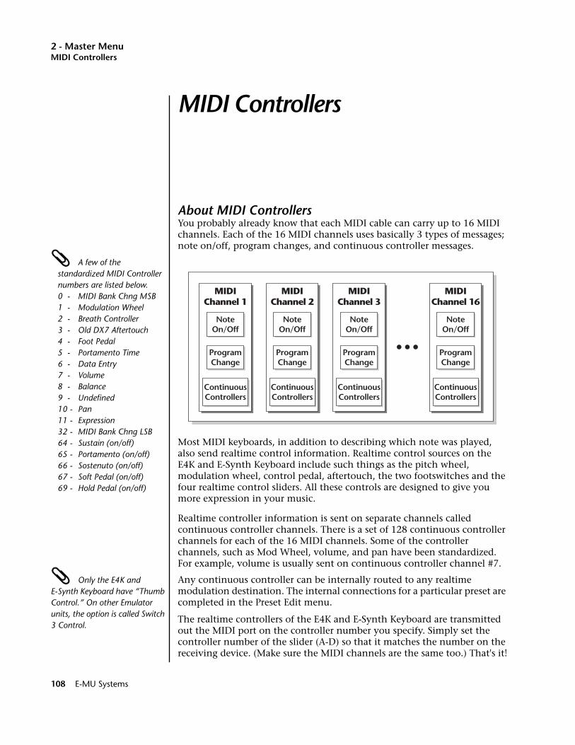
2 - Master MenuMIDI Controllers
MIDI Controllers
About MIDI ControllersYou probably already know that each MIDI cable can carry up to 16 MIDI channels. Each of the 16 MIDI channels uses basically 3 types of messages; note on/off, program changes, and continuous controller messages.
A few of the standardized MIDI Controller numbers are listed below.0 - MIDI Bank Chng MSB1 - Modulation Wheel 2 - Breath Controller3 - Old DX7 Aftertouch4 - Foot Pedal5 - Portamento Time6 - Data Entry7 - Volume8 - Balance9 - Undefined10 - Pan11 - Expression32 - MIDI Bank Chng LSB64 - Sustain (on/off)65 - Portamento (on/off)66 - Sostenuto (on/off)67 - Soft Pedal (on/off)69 - Hold Pedal (on/off)
Most MIDI keyboards, in addition to describing which note was played, also send realtime control information. Realtime control sources on the E4K and E-Synth Keyboard include such things as the pitch wheel, modulation wheel, control pedal, aftertouch, the two footswitches and the four realtime control sliders. All these controls are designed to give you more expression in your music.
Realtime controller information is sent on separate channels called continuous controller channels. There is a set of 128 continuous controller channels for each of the 16 MIDI channels. Some of the controller channels, such as Mod Wheel, volume, and pan have been standardized. For example, volume is usually sent on continuous controller channel #7.
Only the E4K and E-Synth Keyboard have “Thumb Control.” On other Emulator units, the option is called Switch 3 Control.
Any continuous controller can be internally routed to any realtime modulation destination. The internal connections for a particular preset are completed in the Preset Edit menu.
The realtime controllers of the E4K and E-Synth Keyboard are transmitted out the MIDI port on the controller number you specify. Simply set the controller number of the slider (A-D) so that it matches the number on the receiving device. (Make sure the MIDI channels are the same too.) That's it!
MIDIChannel 1
NoteOn/Off
ProgramChange
ContinuousControllers
MIDIChannel 2
NoteOn/Off
ProgramChange
ContinuousControllers
MIDIChannel 3
NoteOn/Off
ProgramChange
ContinuousControllers
MIDIChannel 16
NoteOn/Off
ProgramChange
ContinuousControllers
108 E-MU Systems
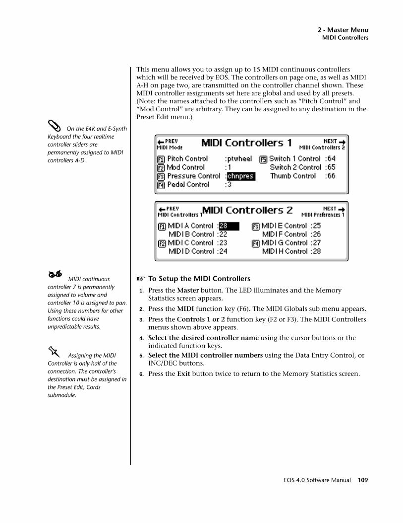
2 - Master MenuMIDI Controllers
This menu allows you to assign up to 15 MIDI continuous controllers which will be received by EOS. The controllers on page one, as well as MIDI A-H on page two, are transmitted on the controller channel shown. These MIDI controller assignments set here are global and used by all presets. (Note: the names attached to the controllers such as “Pitch Control” and “Mod Control” are arbitrary. They can be assigned to any destination in the Preset Edit menu.)
On the E4K and E-Synth Keyboard the four realtime controller sliders are permanently assigned to MIDI controllers A-D.
____ MIDI continuous controller 7 is permanently assigned to volume and controller 10 is assigned to pan. Using these numbers for other functions could have unpredictable results.
v To Setup the MIDI Controllers
1. Press the Master button. The LED illuminates and the Memory Statistics screen appears.
2. Press the MIDI function key (F6). The MIDI Globals sub menu appears.
3. Press the Controls 1 or 2 function key (F2 or F3). The MIDI Controllers menus shown above appears.
4. Select the desired controller name using the cursor buttons or the indicated function keys.
OOOO Assigning the MIDI Controller is only half of the connection. The controller's destination must be assigned in the Preset Edit, Cords submodule.
5. Select the MIDI controller numbers using the Data Entry Control, or INC/DEC buttons.
6. Press the Exit button twice to return to the Memory Statistics screen.
EOS 4.0 Software Manual 109
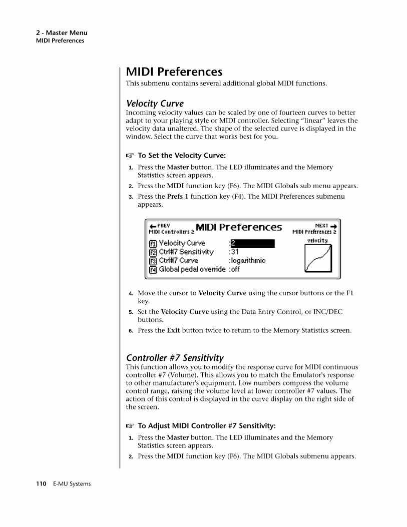
2 - Master MenuMIDI Preferences
MIDI PreferencesThis submenu contains several additional global MIDI functions.
Velocity CurveIncoming velocity values can be scaled by one of fourteen curves to better adapt to your playing style or MIDI controller. Selecting “linear” leaves the velocity data unaltered. The shape of the selected curve is displayed in the window. Select the curve that works best for you.
v To Set the Velocity Curve:
1. Press the Master button. The LED illuminates and the Memory Statistics screen appears.
2. Press the MIDI function key (F6). The MIDI Globals sub menu appears.
3. Press the Prefs 1 function key (F4). The MIDI Preferences submenu appears.
4. Move the cursor to Velocity Curve using the cursor buttons or the F1 key.
5. Set the Velocity Curve using the Data Entry Control, or INC/DEC buttons.
6. Press the Exit button twice to return to the Memory Statistics screen.
Controller #7 SensitivityThis function allows you to modify the response curve for MIDI continuous controller #7 (Volume). This allows you to match the Emulator's response to other manufacturer's equipment. Low numbers compress the volume control range, raising the volume level at lower controller #7 values. The action of this control is displayed in the curve display on the right side of the screen.
v To Adjust MIDI Controller #7 Sensitivity:
1. Press the Master button. The LED illuminates and the Memory Statistics screen appears.
2. Press the MIDI function key (F6). The MIDI Globals submenu appears.
110 E-MU Systems
2 - Master MenuMIDI Preferences
3. Press the Prefs 1 function key (F4). The MIDI Preferences 1 submenu appears.
4. Move the cursor to Ctrl #7 Sensitivity or use the F2 key.
5. While sending controller #7 messages adjust the sensitivity using the Data Entry Control, or INC/DEC buttons.
6. Press the Exit button twice to return to the Memory Statistics screen.
Controller #7 CurveThis is another adjustment to help match the Emulator to other manufac-turer's equipment. Three curves are provided: Linear, Squared or Logarithmic. The action of this control is displayed in the curve display on the right side of the screen.
v To Adjust MIDI Controller #7 Curve:
1. Press the Master button. The LED illuminates and the Memory Statistics screen appears.
2. Press the MIDI function key (F6). The MIDI Globals sub menu appears.
3. Press the Prefs 1 function key (F4). The MIDI Preferences 1 submenu appears.
4. Move the cursor to Ctrl #7 Curve or use the F3 function key.
5. While sending controller #7 messages adjust the curve using the Data Entry Control, or INC/DEC buttons.
6. Press the Exit button twice to return to the Memory Statistics screen.
Global Pedal OverrideThis feature, when enabled, overrides any footpedal assignments made in the preset and forces the footpedal to become a master volume pedal which emulates the front panel volume control.
v To Turn Global Pedal Override On/Off
1. Press the Master button. The LED illuminates and the Memory Statistics screen appears.
2. Press the MIDI function key (F6). The MIDI Globals sub menu appears.
3. Press the Prefs 1 function key (F4). The MIDI Preferences 1 submenu appears.
4. Move the cursor to Global Pedal Override using the cursor buttons or the F4 function key.
5. Turn Global Pedal Override On or Off using the Data Entry Control, or INC/DEC buttons.
6. Press the Exit button twice to return to the Memory Statistics screen.
EOS 4.0 Software Manual 111

2 - Master MenuMIDI Preferences
Receive Program Change On/OffWith Receive Program Change turned on, EOS applies any incoming MIDI program change commands. If disabled (turned off), MIDI program changes are ignored by the system.
To Change Program Banks via MIDI, send:1) Continuous Controller 00 = 0 2) Cont. Controller 32 = Bank # 3) Program Change
This allows you to access presets higher than 128 via MIDI.
On your sequencer: Use Continuous Controller #32
v To Turn Receive Program Change On/Off
1. Press the Master button. The LED illuminates and the Memory Statistics screen appears.
2. Press the MIDI function key (F6). The MIDI Globals sub menu appears.
3. Press the Prefs 2 function key (F5). The MIDI Preferences 2 submenu appears.
4. Move the cursor to Receive Program Change On/Off using the Cursor buttons or the F1 key.
5. Turn Receive Program Change On or Off using the Data Entry Control, or INC/DEC buttons.
6. Press the Exit button twice to return to the Memory Statistics screen.
Send Program Change On/OffWith the Send Program Change enabled, MIDI program change commands are sent to the MIDI Out port. If disabled, preset change commands are not delivered to the MIDI out port. Enable this feature if you want to send MIDI Program Change commands to another instrument or unit through the MIDI out connection on the Emulator.
v To Send Program Change:
Program Change commands will not be transmitted while EOS is in Multi mode.
1. Press the Master button. The LED illuminates and the Memory Statistics screen appears.
2. Press the MIDI function key (F6). The MIDI Globals submenu appears.
3. Press the Prefs 2 function key (F5). The MIDI Preferences 2 submenu appears.
4. Move the cursor to Send Program Change On/Off using the cursor buttons or the F2 key.
5. Turn Send Program Change On or Off using the Data Entry Control, or INC/DEC buttons.
6. Press the Exit button twice to return to the Memory Statistics screen.
112 E-MU Systems
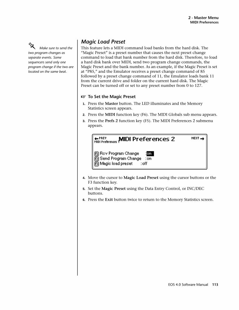
2 - Master MenuMIDI Preferences
Magic Load PresetOOOO Make sure to send the two program changes as separate events. Some sequencers send only one program change if the two are located on the same beat.
This feature lets a MIDI command load banks from the hard disk. The “Magic Preset” is a preset number that causes the next preset change command to load that bank number from the hard disk. Therefore, to load a hard disk bank over MIDI, send two program change commands, the Magic Preset and the bank number. As an example, if the Magic Preset is set at “P85,” and the Emulator receives a preset change command of 85 followed by a preset change command of 11, the Emulator loads bank 11 from the current drive and folder on the current hard disk. The Magic Preset can be turned off or set to any preset number from 0 to 127.
v To Set the Magic Preset
1. Press the Master button. The LED illuminates and the Memory Statistics screen appears.
2. Press the MIDI function key (F6). The MIDI Globals sub menu appears.
3. Press the Prefs 2 function key (F5). The MIDI Preferences 2 submenu appears.
4. Move the cursor to Magic Load Preset using the cursor buttons or the F3 function key.
5. Set the Magic Preset using the Data Entry Control, or INC/DEC buttons.
6. Press the Exit button twice to return to the Memory Statistics screen.
EOS 4.0 Software Manual 113

2 - Master Menu
114 E-MU Systems

3 - Effects
3Effects
EOS 4.0 Software Manual 115

3 - Effects
116 E-MU Systems
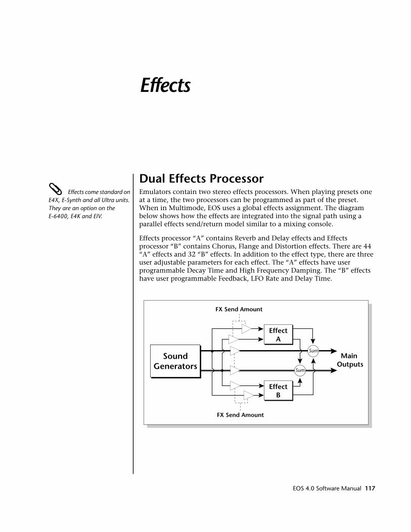
Effects
Dual Effects Processor Effects come standard on E4X, E-Synth and all Ultra units. They are an option on the E-6400, E4K and EIV.
Emulators contain two stereo effects processors. When playing presets one at a time, the two processors can be programmed as part of the preset. When in Multimode, EOS uses a global effects assignment. The diagram below shows how the effects are integrated into the signal path using a parallel effects send/return model similar to a mixing console.
Effects processor “A” contains Reverb and Delay effects and Effects processor “B” contains Chorus, Flange and Distortion effects. There are 44 “A” effects and 32 “B” effects. In addition to the effect type, there are three user adjustable parameters for each effect. The “A” effects have user programmable Decay Time and High Frequency Damping. The “B” effects have user programmable Feedback, LFO Rate and Delay Time.
EffectA
Sum
SumMain
OutputsSound
Generators
EffectB
FX Send Amount
FX Send Amount
EOS 4.0 Software Manual 117
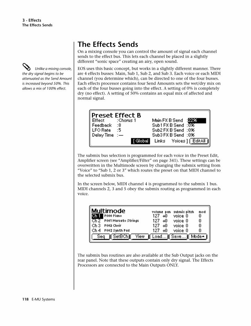
3 - EffectsThe Effects Sends
The Effects SendsOn a mixing console you can control the amount of signal each channel sends to the effect bus. This lets each channel be placed in a slightly different “sonic space” creating an airy, open sound.
Unlike a mixing console, the dry signal begins to be attenuated as the Send Amount is increased beyond 50%. This allows a mix of 100% effect.
EOS uses this basic concept, but works in a slightly different manner. There are 4 effects busses: Main, Sub 1, Sub 2, and Sub 3. Each voice or each MIDI channel (you determine which), can be directed to one of the four busses. Each effects processor contains four Send Amounts sets the wet/dry mix on each of the four busses going into the effect. A setting of 0% is completely dry (no effect). A setting of 50% contains an equal mix of affected and normal signal.
The submix bus selection is programmed for each voice in the Preset Edit, Amplifier screen (see “Amplifier/Filter” on page 341). These settings can be overwritten in the Multimode screen by changing the submix setting from “Voice” to “Sub 1, 2 or 3” which routes the preset on that MIDI channel to the selected submix bus.
In the screen below, MIDI channel 4 is programmed to the submix 1 bus. MIDI channels 2, 3 and 5 obey the submix routing as programmed in each voice.
The submix bus routines are also available at the Sub Output jacks on the rear panel. Note that these outputs contain only dry signal. The Effects Processors are connected to the Main Outputs ONLY.
118 E-MU Systems
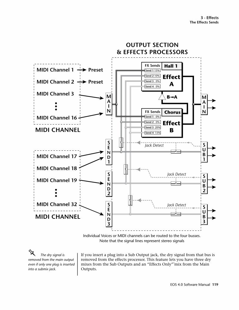
3 - EffectsThe Effects Sends
OOOO The dry signal is removed from the main output even if only one plug is inserted into a submix jack.
If you insert a plug into a Sub Output jack, the dry signal from that bus is removed from the effects processor. This feature lets you have three dry mixes from the Sub Outputs and an “Effects Only” mix from the Main Outputs.
MAIN
SUB1
MAIN
OUTPUT SECTION& EFFECTS PROCESSORS
MIDI Channel 17
MIDI Channel 18
MIDI Channel 19
MIDI Channel 32
MIDI Channel 1
MIDI Channel 2
MIDI Channel 3
MIDI Channel 16
MIDI CHANNEL
MIDI CHANNEL
Hall 1
EffectA
Chorus
EffectB
B➟A
Preset
Preset
Jack Detect
Jack Detect
SUB2
SUB3
FX Sends
Send 2 10%
Send 3 0%
Send 4 0%
Jack Detect
Send 1 15%
FX SendsSend 1 0%
Send 4 15%
Send 3 20%
Send 2 0%
SEND1
SEND2
SEND3
Individual Voices or MIDI channels can be routed to the four busses.Note that the signal lines represent stereo signals
EOS 4.0 Software Manual 119
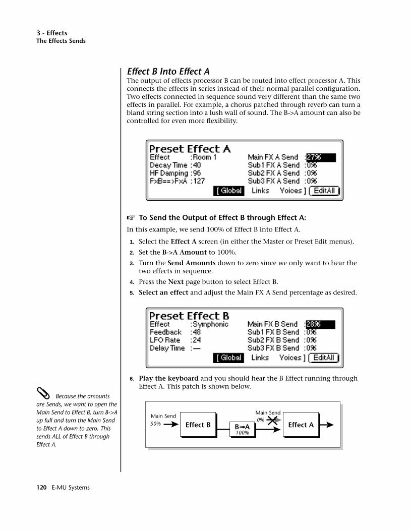
3 - EffectsThe Effects Sends
Effect B Into Effect AThe output of effects processor B can be routed into effect processor A. This connects the effects in series instead of their normal parallel configuration. Two effects connected in sequence sound very different than the same two effects in parallel. For example, a chorus patched through reverb can turn a bland string section into a lush wall of sound. The B->A amount can also be controlled for even more flexibility.
v To Send the Output of Effect B through Effect A:
In this example, we send 100% of Effect B into Effect A.
1. Select the Effect A screen (in either the Master or Preset Edit menus).
2. Set the B->A Amount to 100%.
3. Turn the Send Amounts down to zero since we only want to hear the two effects in sequence.
4. Press the Next page button to select Effect B.
5. Select an effect and adjust the Main FX A Send percentage as desired.
6. Play the keyboard and you should hear the B Effect running through Effect A. This patch is shown below.
Because the amounts are Sends, we want to open the Main Send to Effect B, turn B->A up full and turn the Main Send to Effect A down to zero. This sends ALL of Effect B through Effect A.
Effect BMain Send
Main Send
Effect A50%
100%
0%B➟A
120 E-MU Systems
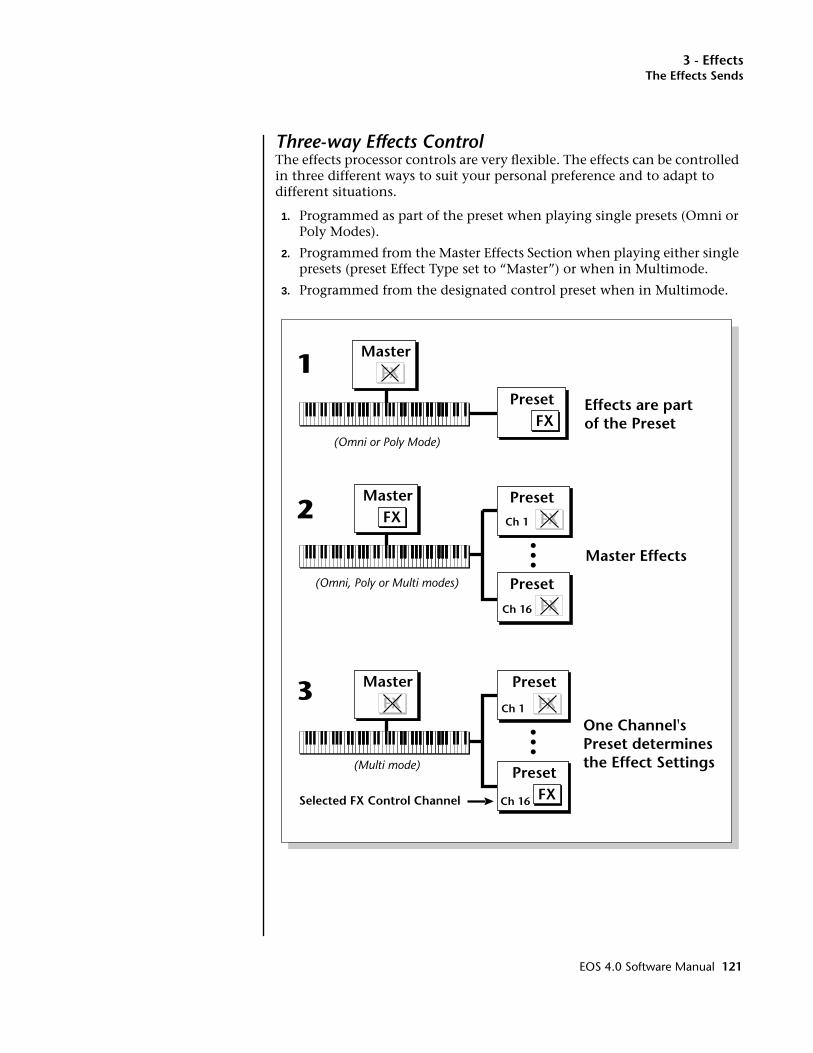
3 - EffectsThe Effects Sends
Three-way Effects ControlThe effects processor controls are very flexible. The effects can be controlled in three different ways to suit your personal preference and to adapt to different situations.
1. Programmed as part of the preset when playing single presets (Omni or Poly Modes).
2. Programmed from the Master Effects Section when playing either single presets (preset Effect Type set to “Master”) or when in Multimode.
3. Programmed from the designated control preset when in Multimode.
PresetFX
MasterFX
Effects are partof the Preset
1
(Omni or Poly Mode)
MasterFX
Preset
Ch 16 FX
Master Effects
PresetFXCh 1
2
(Omni, Poly or Multi modes)
PresetFX
Preset
FX
FX
Master
Ch 16
Ch 1
Selected FX Control Channel
One Channel'sPreset determinesthe Effect Settings
3
(Multi mode)
EOS 4.0 Software Manual 121
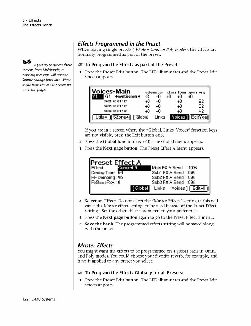
3 - EffectsThe Effects Sends
Effects Programmed in the PresetWhen playing single presets (Whole = Omni or Poly modes), the effects are normally programmed as part of the preset.
____ If you try to access these screens from Multimode, a warning message will appear. Simply change back into Whole mode from the Mode screen on the main page.
v To Program the Effects as part of the Preset:
1. Press the Preset Edit button. The LED illuminates and the Preset Edit screen appears.
If you are in a screen where the “Global, Links, Voices” function keys are not visible, press the Exit button once.
2. Press the Global function key (F3). The Global menu appears.
3. Press the Next page button. The Preset Effect A menu appears.
4. Select an Effect. Do not select the “Master Effects” setting as this will cause the Master effect settings to be used instead of the Preset Effect settings. Set the other effect parameters to your preference.
5. Press the Next page button again to go to the Preset Effect B menu.
6. Save the bank. The programmed effects setting will be saved along with the preset.
Master EffectsYou might want the effects to be programmed on a global basis in Omni and Poly modes. You could choose your favorite reverb, for example, and have it applied to any preset you select.
v To Program the Effects Globally for all Presets:
1. Press the Preset Edit button. The LED illuminates and the Preset Edit screen appears.
122 E-MU Systems

3 - EffectsThe Effects Sends
If you are in a screen where the “Global, Links, Voices” function keys are not visible, press the Exit button once.
2. Press the Global function key (F3). The Global menu appears.
3. Press the Next page button. The Preset Effect A menu appears.
4. Set the Effect to the “Default” setting which will cause the Master Effect settings to be used.
5. Press the Next page button again to go to the Preset Effect B menu. Set the Effect to the Default setting if you wish the Master settings to be used.
6. Change each preset in the bank to the Default setting if you want the Master Effect setting used on all presets.
7. Save the bank.
Using Master Effects Settings in MultimodeIn Multimode, the two effects processors can be controlled from the Master Effects settings or they can follow the effects settings of the preset on a special MIDI channel. Because up to 32 presets can play at once in multi mode, the effects cannot be programmed at the preset level. There are only two effects processors!
v To Program the Effects Globally for all Presets:
1. Press the Master button. The LED illuminates and the Memory Statistics screen appears.
2. Press the FX function key. A second row of MIDI options appears.
EOS 4.0 Software Manual 123
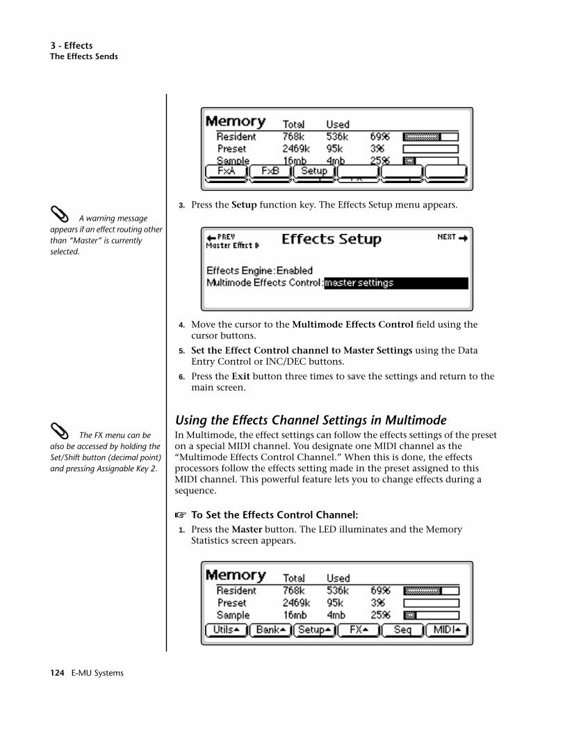
3 - EffectsThe Effects Sends
3. Press the Setup function key. The Effects Setup menu appears. A warning message appears if an effect routing other than “Master” is currently selected.
4. Move the cursor to the Multimode Effects Control field using the cursor buttons.
5. Set the Effect Control channel to Master Settings using the Data Entry Control or INC/DEC buttons.
6. Press the Exit button three times to save the settings and return to the main screen.
Using the Effects Channel Settings in Multimode The FX menu can be also be accessed by holding the Set/Shift button (decimal point) and pressing Assignable Key 2.
In Multimode, the effect settings can follow the effects settings of the preset on a special MIDI channel. You designate one MIDI channel as the “Multimode Effects Control Channel.” When this is done, the effects processors follow the effects setting made in the preset assigned to this MIDI channel. This powerful feature lets you to change effects during a sequence.
v To Set the Effects Control Channel:1. Press the Master button. The LED illuminates and the Memory
Statistics screen appears.
124 E-MU Systems

3 - EffectsThe Effects Sends
2. Press the FX function key. A second row of MIDI options appears.
3. Press the Setup function key. The Effects Setup menu appears.
4. Move the cursor to the Multimode Effect Control field using the cursor buttons.
5. Set the Effect Control channel using the Data Entry Control or INC/DEC buttons.
6. Press the Exit button three times to save the settings and return to the main screen.
Effects BypassThis control provides a true bypass of the effects engine. Bypass is a useful feature if you are using external effects at the mixing console and want to turn the effects off for all presets.
v To Bypass the Effects:
1. Press the Master button. The LED illuminates and the Memory Statistics screen appears.
2. Press the FX function key (F4). A second row of Effects options appears.
EOS 4.0 Software Manual 125
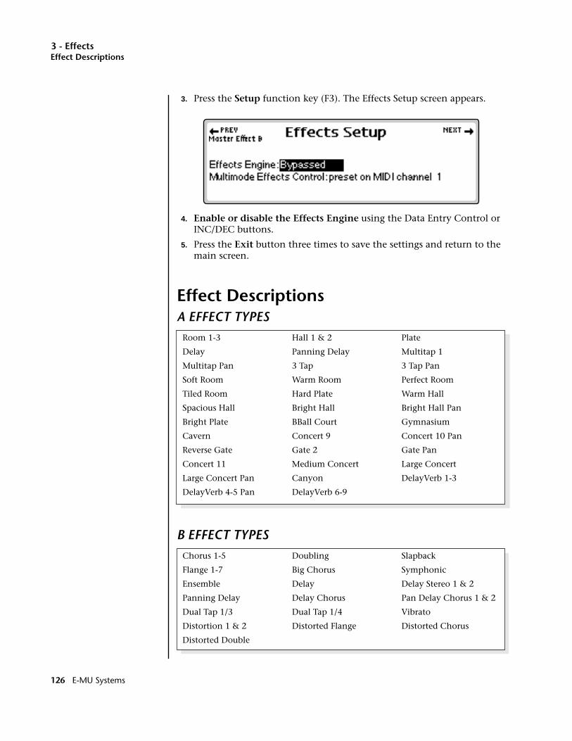
3 - EffectsEffect Descriptions
3. Press the Setup function key (F3). The Effects Setup screen appears.
4. Enable or disable the Effects Engine using the Data Entry Control or INC/DEC buttons.
5. Press the Exit button three times to save the settings and return to the main screen.
Effect DescriptionsA EFFECT TYPES
B EFFECT TYPES
Room 1-3 Hall 1 & 2 Plate
Delay Panning Delay Multitap 1
Multitap Pan 3 Tap 3 Tap Pan
Soft Room Warm Room Perfect Room
Tiled Room Hard Plate Warm Hall
Spacious Hall Bright Hall Bright Hall Pan
Bright Plate BBall Court Gymnasium
Cavern Concert 9 Concert 10 Pan
Reverse Gate Gate 2 Gate Pan
Concert 11 Medium Concert Large Concert
Large Concert Pan Canyon DelayVerb 1-3
DelayVerb 4-5 Pan DelayVerb 6-9
Chorus 1-5 Doubling Slapback
Flange 1-7 Big Chorus Symphonic
Ensemble Delay Delay Stereo 1 & 2
Panning Delay Delay Chorus Pan Delay Chorus 1 & 2
Dual Tap 1/3 Dual Tap 1/4 Vibrato
Distortion 1 & 2 Distorted Flange Distorted Chorus
Distorted Double
126 E-MU Systems
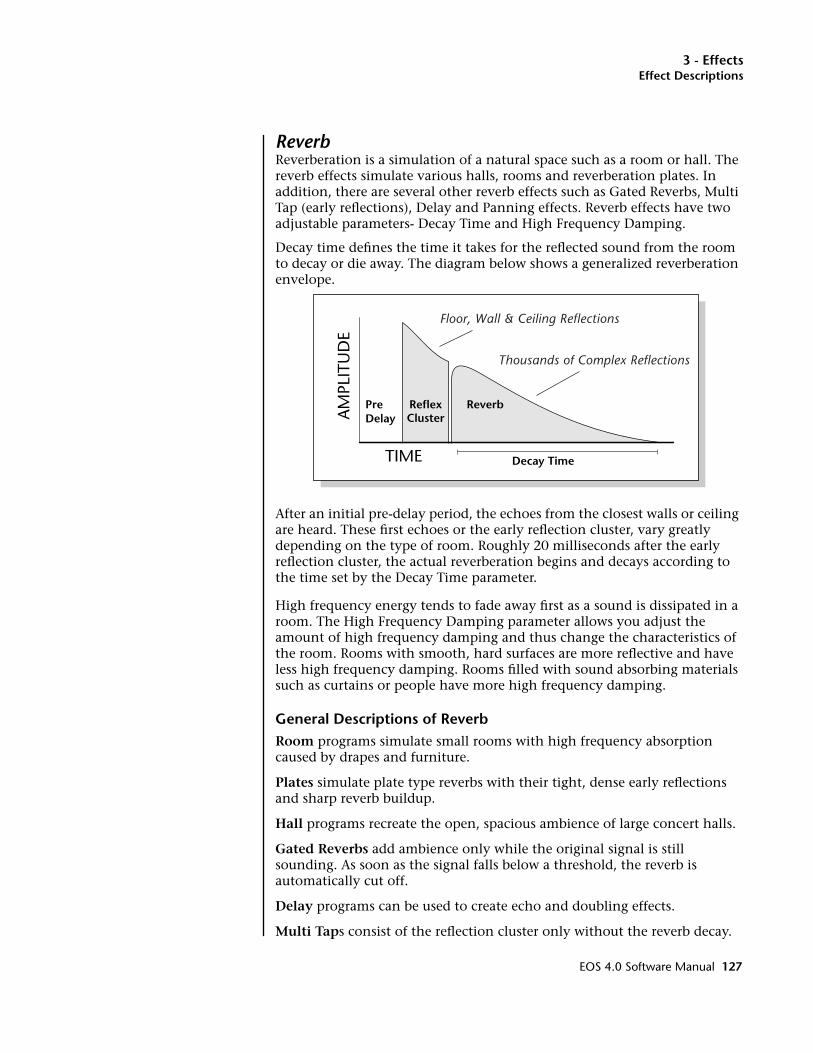
3 - EffectsEffect Descriptions
ReverbReverberation is a simulation of a natural space such as a room or hall. The reverb effects simulate various halls, rooms and reverberation plates. In addition, there are several other reverb effects such as Gated Reverbs, Multi Tap (early reflections), Delay and Panning effects. Reverb effects have two adjustable parameters- Decay Time and High Frequency Damping.
Decay time defines the time it takes for the reflected sound from the room to decay or die away. The diagram below shows a generalized reverberation envelope.
After an initial pre-delay period, the echoes from the closest walls or ceiling are heard. These first echoes or the early reflection cluster, vary greatly depending on the type of room. Roughly 20 milliseconds after the early reflection cluster, the actual reverberation begins and decays according to the time set by the Decay Time parameter.
High frequency energy tends to fade away first as a sound is dissipated in a room. The High Frequency Damping parameter allows you adjust the amount of high frequency damping and thus change the characteristics of the room. Rooms with smooth, hard surfaces are more reflective and have less high frequency damping. Rooms filled with sound absorbing materials such as curtains or people have more high frequency damping.
General Descriptions of ReverbRoom programs simulate small rooms with high frequency absorption caused by drapes and furniture.
Plates simulate plate type reverbs with their tight, dense early reflections and sharp reverb buildup.
Hall programs recreate the open, spacious ambience of large concert halls.
Gated Reverbs add ambience only while the original signal is still sounding. As soon as the signal falls below a threshold, the reverb is automatically cut off.
Delay programs can be used to create echo and doubling effects.
Multi Taps consist of the reflection cluster only without the reverb decay.
TIME
AM
PLIT
UD
E
PreDelay
ReverbReflexCluster
Decay Time
Floor, Wall & Ceiling Reflections
Thousands of Complex Reflections
EOS 4.0 Software Manual 127
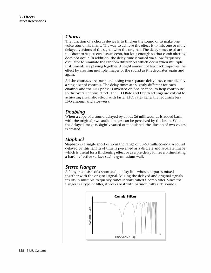
3 - EffectsEffect Descriptions
ChorusThe function of a chorus device is to thicken the sound or to make one voice sound like many. The way to achieve the effect is to mix one or more delayed versions of the signal with the original. The delay times used are too short to be perceived as an echo, but long enough so that comb filtering does not occur. In addition, the delay time is varied via a low frequency oscillator to simulate the random differences which occur when multiple instruments are playing together. A slight amount of feedback improves the effect by creating multiple images of the sound as it recirculates again and again.
All the choruses are true stereo using two separate delay lines controlled by a single set of controls. The delay times are slightly different for each channel and the LFO phase is inverted on one channel to help contribute to the overall chorus effect. The LFO Rate and Depth settings are critical to achieving a realistic effect, with faster LFO, rates generally requiring less LFO amount and vice-versa.
DoublingWhen a copy of a sound delayed by about 26 milliseconds is added back with the original, two audio images can be perceived by the brain. When the delayed image is slightly varied or modulated, the illusion of two voices is created.
SlapbackSlapback is a single short echo in the range of 50-60 milliseconds. A sound delayed by this length of time is perceived as a discrete and separate image which is useful for a thickening effect or as a pre-delay for reverb simulating a hard, reflective surface such a gymnasium wall.
Stereo FlangerA flanger consists of a short audio delay line whose output is mixed together with the original signal. Mixing the delayed and original signals results in multiple frequency cancellations called a comb filter. Since the flanger is a type of filter, it works best with harmonically rich sounds.
FREQUENCY (log)
AM
PLIT
UD
E (d
B)
Comb Filter
128 E-MU Systems
3 - EffectsEffect Descriptions
Flanging was originally created using two tape recorders playing identical recordings. By exactly synchronizing the two decks and then slowing the speed of one by grasping the tape reel flanges, the flanging effect was born.
The flanger is a stereo device consisting of two separate delay lines controlled by a single set of controls. A Low Frequency Oscillator (LFO) varies this initial delay setting, changing the frequency of the notches and adding animation to the sound. LFO Rate controls the rate of change and LFO Depth controls how much the LFO changes the delay.
The Feedback control sends some of the delayed signal through the delay line again. When feedback is used the comb filter notches are deepened.
DelayDelay is an effect which can be used for doubling, reverb pre-delay, or echoes. Delay Time is variable from 0-635 mS and controls the time between echoes and Feedback and determines how long the echoes continue sounding. “Infinite” delay effects are also possible without the risk of runaway.
Stereo DelaySimilar to delay except that the delay line outputs a stereo signal from the mono input. The two output signals are a few milliseconds apart to create a stereo image. The delay times are variable from 0-635 mS.
Panning DelayA panning delay is similar to the normal delay lines except that the echoes bounce back and forth between the two stereo speakers.
Dual TapThese are delay lines where the signal is “tapped off” at two unevenly spaced locations. When feedback is used, multiple complex echoes are produced. The fraction in the name (i.e. 1/3, 1/4) refers to the distance between the taps.
VibratoBasically, this a delay line modulated by an LFO, but with none of the original signal added in. The LFO modulation creates a Doppler shift and a resultant cyclical pitch shift. The vibrato created in this manner sounds very different than vibrato created by frequency modulating the sample.
DistortionDistortion uses a technique called “soft-clipping” to create additional harmonics in the signal. As the level increases, the top of the waveform becomes somewhat squared. As the level increases further, it transforms into a true square wave.
EOS 4.0 Software Manual 129

3 - Effects
130 E-MU Systems

4 - Sequencer
4Sequencer
EOS 4.0 Software Manual 131

4 - Sequencer
132 E-MU Systems

4 - Sequencer
Sequence ManageOOOO See Chapter 1: The Basics, for step by step instructions on how to create a sequence.
EOS 3 contains a powerful 48-track onboard sequencer which is always ready and available to capture your musical ideas. The sequencer's easy to use interface lets you lay down tracks almost as fast as you can play them. After recording, you can use its powerful editing capabilities to rearrange and polish your creation in almost any imaginable way. Editing is easy, thanks to intuitive Copy and Paste style editing and an impressive array of tools which allow you to: Quantize, Transpose, Scale Velocity or Rechan-nelize Tracks. You can also Channelize or Quantize MIDI data while recording.
Program Changes, Pan Position, Initial Volume, Submix, Tempo, Controller Changes and SysEx data can all be stored with the sequence. You can record and save up to 50 sequences along with each EOS bank. If Flash RAM is installed (ROM or Flash RAM upgrade), you can save 50 additional sequences to Flash Memory.
Sequencer note capacity is dependent upon the amount of CPU memory installed and how much you have allocated to sequences. As an example, over 400,000 notes can be stored if you have 4 MB of preset RAM. About 97,000 notes can be stored if you have 1 MB of preset RAM.
Sequences can be copied, renamed, and are easily imported or exported as Standard MIDI Files or E-mu’s EIV format. As a bonus feature, the virtual “Jukebox” lets you link up to 7 sequences and play them back in any order.
————————————— Note ——————————————When sequencing on a Rack Emulator with dual MIDI ports, you MUST use Port A for your MIDI input. Port B does not get routed to the sequencer.
———————————————————————————————
EOS 4.0 Software Manual 133
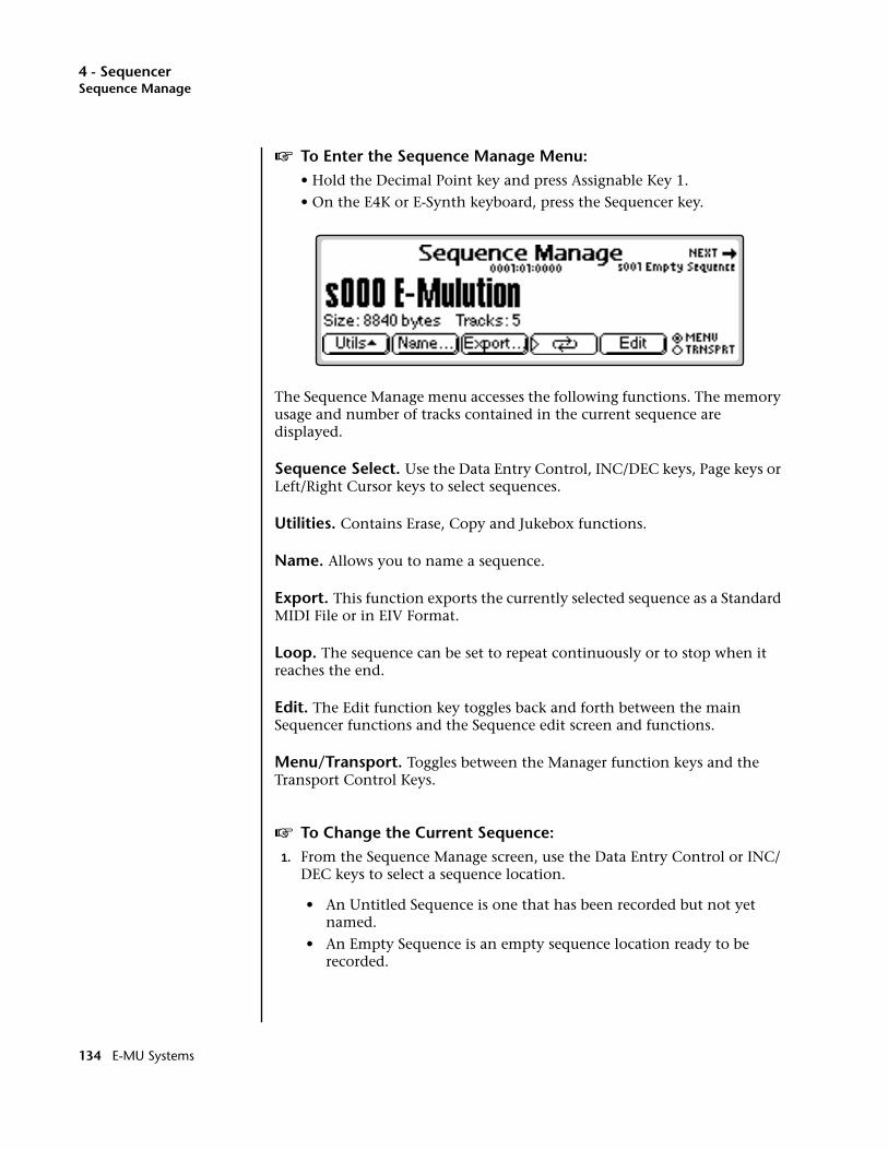
4 - SequencerSequence Manage
v To Enter the Sequence Manage Menu:• Hold the Decimal Point key and press Assignable Key 1.
• On the E4K or E-Synth keyboard, press the Sequencer key.
The Sequence Manage menu accesses the following functions. The memory usage and number of tracks contained in the current sequence are displayed.
Sequence Select. Use the Data Entry Control, INC/DEC keys, Page keys or Left/Right Cursor keys to select sequences.
Utilities. Contains Erase, Copy and Jukebox functions.
Name. Allows you to name a sequence.
Export. This function exports the currently selected sequence as a Standard MIDI File or in EIV Format.
Loop. The sequence can be set to repeat continuously or to stop when it reaches the end.
Edit. The Edit function key toggles back and forth between the main Sequencer functions and the Sequence edit screen and functions.
Menu/Transport. Toggles between the Manager function keys and the Transport Control Keys.
v To Change the Current Sequence:1. From the Sequence Manage screen, use the Data Entry Control or INC/
DEC keys to select a sequence location.
• An Untitled Sequence is one that has been recorded but not yet named.
• An Empty Sequence is an empty sequence location ready to be recorded.
134 E-MU Systems
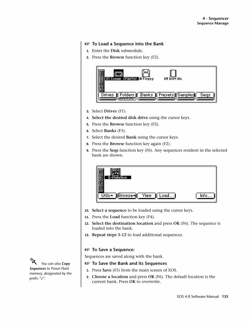
4 - SequencerSequence Manage
v To Load a Sequence into the Bank1. Enter the Disk submodule.
2. Press the Browse function key (F2).
3. Select Drives (F1).
4. Select the desired disk drive using the cursor keys.
5. Press the Browse function key (F2).
6. Select Banks (F3).
7. Select the desired Bank using the cursor keys.
8. Press the Browse function key again (F2).
9. Press the Seqs function key (F6). Any sequences resident in the selected bank are shown.
10. Select a sequence to be loaded using the cursor keys.
11. Press the Load function key (F4).
12. Select the destination location and press OK (F6). The sequence is loaded into the bank.
13. Repeat steps 5-12 to load additional sequences.
v To Save a Sequence:Sequences are saved along with the bank.
OOOO You can also Copy Sequences to Preset Flash memory, designated by the prefix “z”.
v To Save the Bank and its Sequences1. Press Save (F5) from the main screen of EOS.
2. Choose a location and press OK (F6). The default location is the current bank. Press OK to overwrite.
EOS 4.0 Software Manual 135
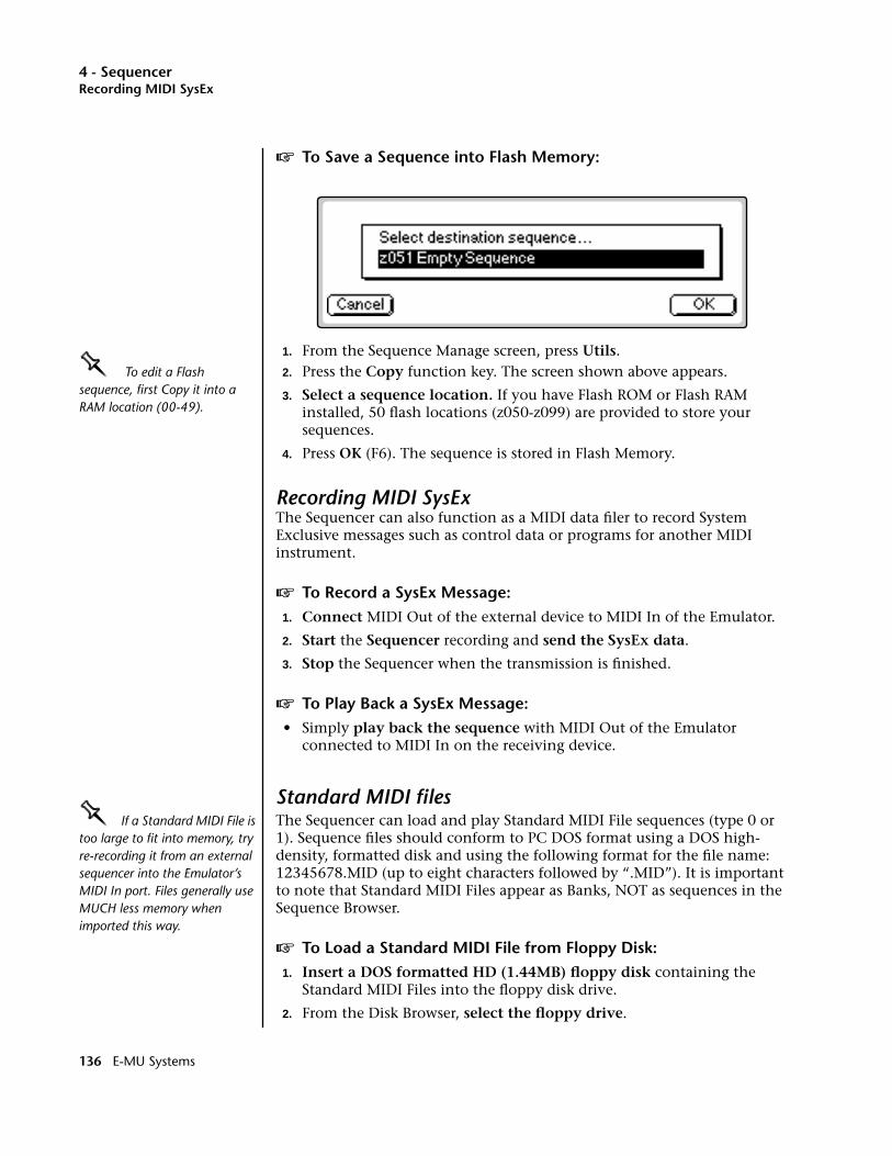
4 - SequencerRecording MIDI SysEx
v To Save a Sequence into Flash Memory:
1. From the Sequence Manage screen, press Utils.OOOO To edit a Flash sequence, first Copy it into a RAM location (00-49).
2. Press the Copy function key. The screen shown above appears.
3. Select a sequence location. If you have Flash ROM or Flash RAM installed, 50 flash locations (z050-z099) are provided to store your sequences.
4. Press OK (F6). The sequence is stored in Flash Memory.
Recording MIDI SysExThe Sequencer can also function as a MIDI data filer to record System Exclusive messages such as control data or programs for another MIDI instrument.
v To Record a SysEx Message:1. Connect MIDI Out of the external device to MIDI In of the Emulator.
2. Start the Sequencer recording and send the SysEx data.
3. Stop the Sequencer when the transmission is finished.
v To Play Back a SysEx Message:• Simply play back the sequence with MIDI Out of the Emulator
connected to MIDI In on the receiving device.
Standard MIDI filesOOOO If a Standard MIDI File is too large to fit into memory, try re-recording it from an external sequencer into the Emulator’s MIDI In port. Files generally use MUCH less memory when imported this way.
The Sequencer can load and play Standard MIDI File sequences (type 0 or 1). Sequence files should conform to PC DOS format using a DOS high-density, formatted disk and using the following format for the file name: 12345678.MID (up to eight characters followed by “.MID”). It is important to note that Standard MIDI Files appear as Banks, NOT as sequences in the Sequence Browser.
v To Load a Standard MIDI File from Floppy Disk:1. Insert a DOS formatted HD (1.44MB) floppy disk containing the
Standard MIDI Files into the floppy disk drive.
2. From the Disk Browser, select the floppy drive.
136 E-MU Systems
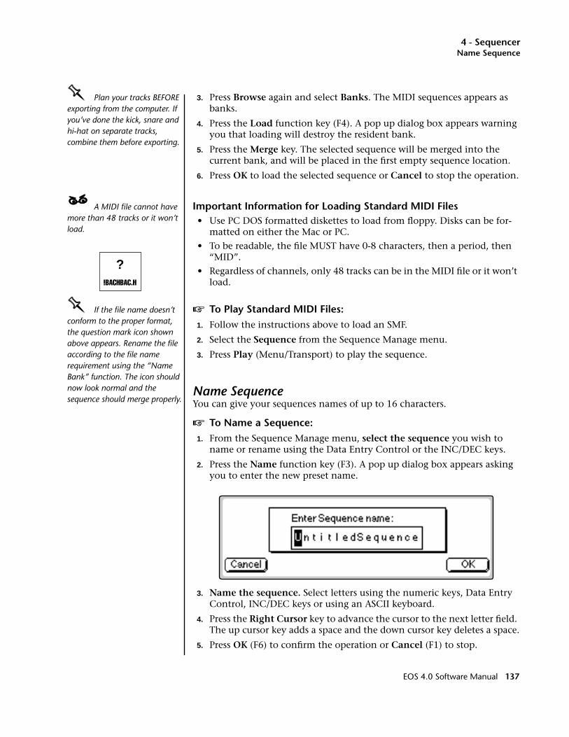
4 - SequencerName Sequence
OOOO Plan your tracks BEFORE exporting from the computer. If you’ve done the kick, snare and hi-hat on separate tracks, combine them before exporting.
3. Press Browse again and select Banks. The MIDI sequences appears as banks.
4. Press the Load function key (F4). A pop up dialog box appears warning you that loading will destroy the resident bank.
5. Press the Merge key. The selected sequence will be merged into the current bank, and will be placed in the first empty sequence location.
6. Press OK to load the selected sequence or Cancel to stop the operation.
____ A MIDI file cannot have more than 48 tracks or it won’t load.
Important Information for Loading Standard MIDI Files• Use PC DOS formatted diskettes to load from floppy. Disks can be for-
matted on either the Mac or PC.
• To be readable, the file MUST have 0-8 characters, then a period, then “MID”.
• Regardless of channels, only 48 tracks can be in the MIDI file or it won’t load.
OOOO If the file name doesn’t conform to the proper format, the question mark icon shown above appears. Rename the file according to the file name requirement using the “Name Bank” function. The icon should now look normal and the sequence should merge properly.
v To Play Standard MIDI Files:1. Follow the instructions above to load an SMF.
2. Select the Sequence from the Sequence Manage menu.
3. Press Play (Menu/Transport) to play the sequence.
Name SequenceYou can give your sequences names of up to 16 characters.
v To Name a Sequence:1. From the Sequence Manage menu, select the sequence you wish to
name or rename using the Data Entry Control or the INC/DEC keys.
2. Press the Name function key (F3). A pop up dialog box appears asking you to enter the new preset name.
3. Name the sequence. Select letters using the numeric keys, Data Entry Control, INC/DEC keys or using an ASCII keyboard.
4. Press the Right Cursor key to advance the cursor to the next letter field. The up cursor key adds a space and the down cursor key deletes a space.
5. Press OK (F6) to confirm the operation or Cancel (F1) to stop.
?!BACHBAC.H
EOS 4.0 Software Manual 137

4 - SequencerExport
ExportThis function allows you to export a sequence as an EIV bank or as a Standard MIDI File. Standard MIDI Files or SMFs are compatible with most computer-based sequencers. EOS uses the MS-DOS format on its floppy disks to facilitate easy file transfers between either IBM or Apple computers.
Exporting a sequence as an EIV bank allows you to transfer sequences between two EOS machines and also allows you to combine sequences from different banks.
v To Export a Sequence:1. From the Sequence Manage menu, select the sequence you wish to
export using the Data Entry Control or the INC/DEC keys.
2. Press the Export function key (F5). The pop up dialog box shown above appears.
3. Select the destination for the exported sequence by using the cursor keys to select the field and the Data Entry Control or INC/DEC keys to change the selection. If you are exporting to a floppy disk, insert a DOS formatted disk into the drive.
4. Select either MIDI (Standard MIDI File) or EIV as the file type.
5. Press OK to export the sequence or Cancel to cancel the operation.
138 E-MU Systems
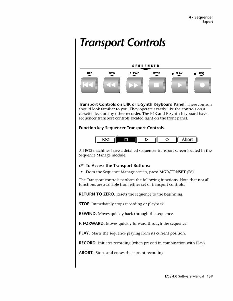
4 - SequencerExport
Transport Controls
Transport Controls on E4K or E-Synth Keyboard Panel. These controls should look familiar to you. They operate exactly like the controls on a cassette deck or any other recorder. The E4K and E-Synth Keyboard have sequencer transport controls located right on the front panel.
Function key Sequencer Transport Controls.
All EOS machines have a detailed sequencer transport screen located in the Sequence Manage module.
v To Access the Transport Buttons:• From the Sequence Manage screen, press MGR/TRNSPT (F6).
The Transport controls perform the following functions. Note that not all functions are available from either set of transport controls.
RETURN TO ZERO. Resets the sequence to the beginning.
STOP. Immediately stops recording or playback.
REWIND. Moves quickly back through the sequence.
F. FORWARD. Moves quickly forward through the sequence.
PLAY. Starts the sequence playing from its current position.
RECORD. Initiates recording (when pressed in combination with Play).
ABORT. Stops and erases the current recording.
EOS 4.0 Software Manual 139
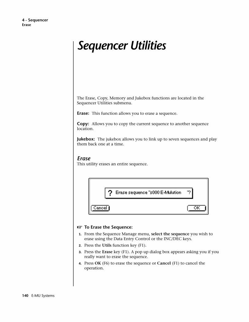
4 - SequencerErase
Sequencer Utilities
The Erase, Copy, Memory and Jukebox functions are located in the Sequencer Utilities submenu.
Erase: This function allows you to erase a sequence.
Copy: Allows you to copy the current sequence to another sequence location.
Jukebox: The jukebox allows you to link up to seven sequences and play them back one at a time.
EraseThis utility erases an entire sequence.
v To Erase the Sequence:1. From the Sequence Manage menu, select the sequence you wish to
erase using the Data Entry Control or the INC/DEC keys.
2. Press the Utils function key (F1).
3. Press the Erase key (F1). A pop up dialog box appears asking you if you really want to erase the sequence.
4. Press OK (F6) to erase the sequence or Cancel (F1) to cancel the operation.
140 E-MU Systems
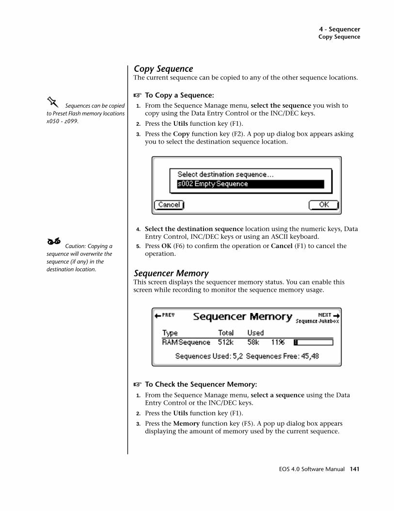
4 - SequencerCopy Sequence
Copy SequenceThe current sequence can be copied to any of the other sequence locations.
v To Copy a Sequence:OOOO Sequences can be copied to Preset Flash memory locations x050 - z099.
1. From the Sequence Manage menu, select the sequence you wish to copy using the Data Entry Control or the INC/DEC keys.
2. Press the Utils function key (F1).
3. Press the Copy function key (F2). A pop up dialog box appears asking you to select the destination sequence location.
4. Select the destination sequence location using the numeric keys, Data Entry Control, INC/DEC keys or using an ASCII keyboard.
____ Caution: Copying a sequence will overwrite the sequence (if any) in the destination location.
5. Press OK (F6) to confirm the operation or Cancel (F1) to cancel the operation.
Sequencer MemoryThis screen displays the sequencer memory status. You can enable this screen while recording to monitor the sequence memory usage.
v To Check the Sequencer Memory:1. From the Sequence Manage menu, select a sequence using the Data
Entry Control or the INC/DEC keys.
2. Press the Utils function key (F1).
3. Press the Memory function key (F5). A pop up dialog box appears displaying the amount of memory used by the current sequence.
EOS 4.0 Software Manual 141
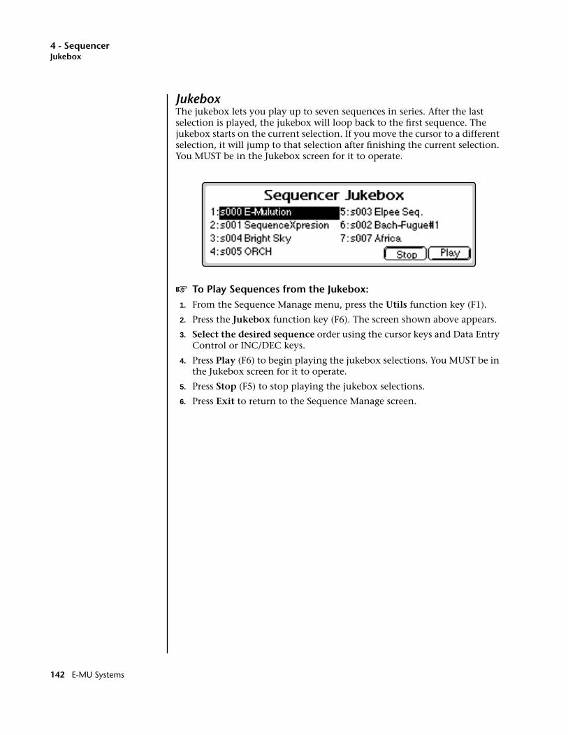
4 - SequencerJukebox
JukeboxThe jukebox lets you play up to seven sequences in series. After the last selection is played, the jukebox will loop back to the first sequence. The jukebox starts on the current selection. If you move the cursor to a different selection, it will jump to that selection after finishing the current selection. You MUST be in the Jukebox screen for it to operate.
v To Play Sequences from the Jukebox:1. From the Sequence Manage menu, press the Utils function key (F1).
2. Press the Jukebox function key (F6). The screen shown above appears.
3. Select the desired sequence order using the cursor keys and Data Entry Control or INC/DEC keys.
4. Press Play (F6) to begin playing the jukebox selections. You MUST be in the Jukebox screen for it to operate.
5. Press Stop (F5) to stop playing the jukebox selections.
6. Press Exit to return to the Sequence Manage screen.
Sequence Edit
142 E-MU Systems
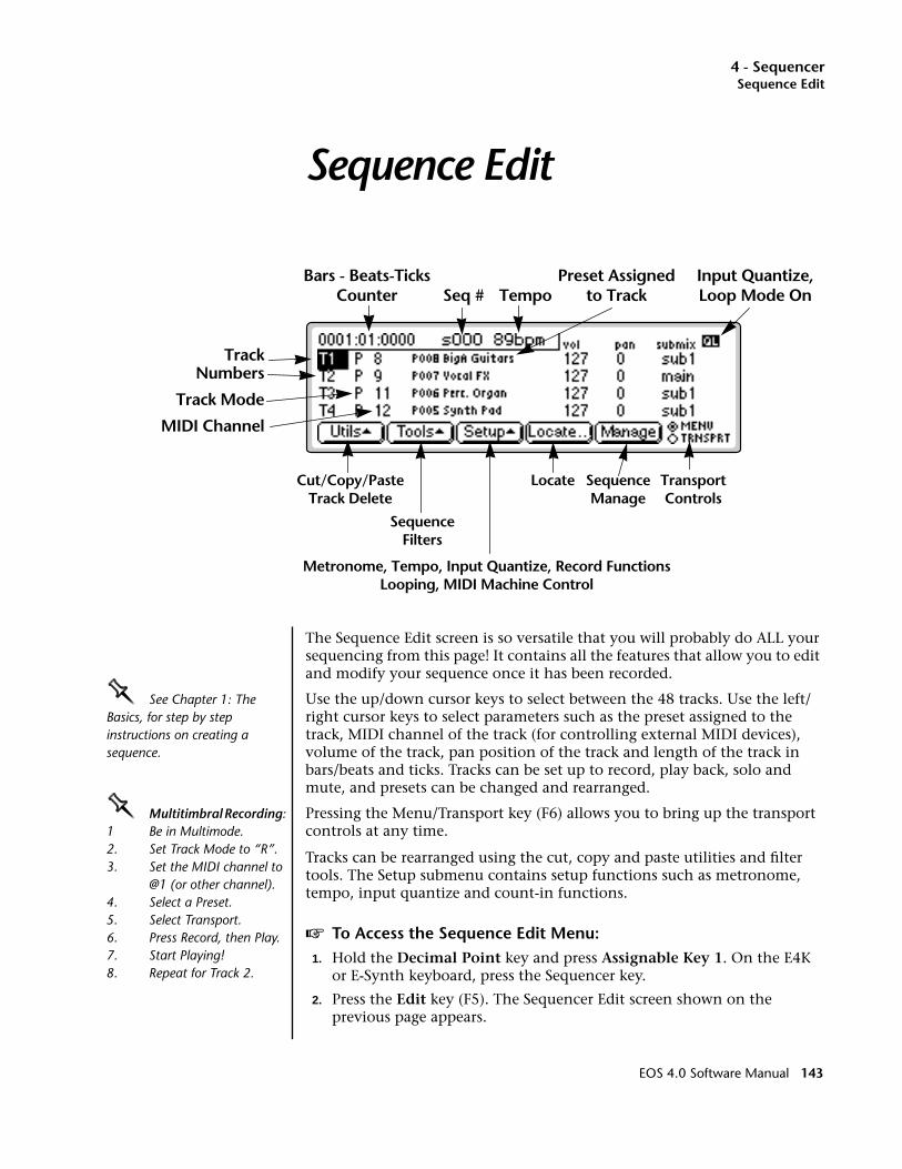
4 - SequencerSequence Edit
Sequence Edit
The Sequence Edit screen is so versatile that you will probably do ALL your sequencing from this page! It contains all the features that allow you to edit and modify your sequence once it has been recorded.
OOOO See Chapter 1: The Basics, for step by step instructions on creating a sequence.
Use the up/down cursor keys to select between the 48 tracks. Use the left/right cursor keys to select parameters such as the preset assigned to the track, MIDI channel of the track (for controlling external MIDI devices), volume of the track, pan position of the track and length of the track in bars/beats and ticks. Tracks can be set up to record, play back, solo and mute, and presets can be changed and rearranged.
OOOO Multitimbral Recording: 1 Be in Multimode.2. Set Track Mode to “R”.3. Set the MIDI channel to
@1 (or other channel).4. Select a Preset.5. Select Transport.6. Press Record, then Play.7. Start Playing!8. Repeat for Track 2.
Pressing the Menu/Transport key (F6) allows you to bring up the transport controls at any time.
Tracks can be rearranged using the cut, copy and paste utilities and filter tools. The Setup submenu contains setup functions such as metronome, tempo, input quantize and count-in functions.
v To Access the Sequence Edit Menu:1. Hold the Decimal Point key and press Assignable Key 1. On the E4K
or E-Synth keyboard, press the Sequencer key.
2. Press the Edit key (F5). The Sequencer Edit screen shown on the previous page appears.
Seq #
TrackNumbers
Track Mode
Bars - Beats-TicksCounter
Cut/Copy/PasteTrack Delete
SequenceFilters
Locate SequenceManage
TransportControls
Metronome, Tempo, Input Quantize, Record FunctionsLooping, MIDI Machine Control
TempoPreset Assigned
to TrackInput Quantize,Loop Mode On
MIDI Channel
EOS 4.0 Software Manual 143
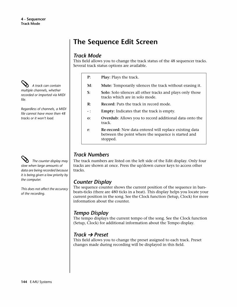
4 - SequencerTrack Mode
The Sequence Edit Screen
Track ModeThis field allows you to change the track status of the 48 sequencer tracks. Several track status options are available.
P: Play: Plays the track.
A track can contain multiple channels, whether recorded or imported via MIDI file.
Regardless of channels, a MIDI file cannot have more then 48 tracks or it won’t load.
M: Mute: Temporarily silences the track without erasing it.
S: Solo: Solo silences all other tracks and plays only thosetracks which are in solo mode.
R: Record: Puts the track in record mode.
- : Empty: Indicates that the track is empty.
o: Overdub: Allows you to record additional data onto thetrack.
r: Re-record: New data entered will replace existing data between the point where the sequence is started and
stopped.
Track Numbers The counter display may slow when large amounts of data are being recorded because it is being given a low priority by the computer.
This does not affect the accuracy of the recording.
The track numbers are listed on the left side of the Edit display. Only four tracks are shown at once. Press the up/down cursor keys to access other tracks.
Counter DisplayThe sequence counter shows the current position of the sequence in bars-beats-ticks (there are 480 ticks in a beat). This display helps you locate your current position in the song. See the Clock function (Setup, Clock) for more information about the counter.
Tempo DisplayThe tempo displays the current tempo of the song. See the Clock function (Setup, Clock) for additional information about the Tempo display.
Track ➔ PresetThis field allows you to change the preset assigned to each track. Preset changes made during recording will be displayed in this field.
144 E-MU Systems
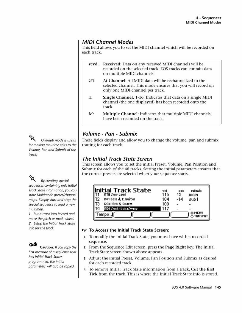
4 - SequencerMIDI Channel Modes
MIDI Channel ModesThis field allows you to set the MIDI channel which will be recorded on each track.
rcvd: Received: Data on any received MIDI channels will be recorded on the selected track. EOS tracks can contain data on multiple MIDI channels.
@1: At Channel: All MIDI data will be rechannelized to theselected channel. This mode ensures that you will record on only one MIDI channel per track.
1: Single Channel, 1-16: Indicates that data on a single MIDI channel (the one displayed) has been recorded onto the track.
M: Multiple Channel: Indicates that multiple MIDI channels have been recorded on the track.
Volume - Pan - SubmixOOOO Overdub mode is useful for making real-time edits to the Volume, Pan and Submix of the track.
These fields display and allow you to change the volume, pan and submix routing for each track.
The Initial Track State ScreenThis screen allows you to set the initial Preset, Volume, Pan Position and Submix for each of the 48 tracks. Setting the initial parameters ensures that the correct presets are selected when your sequence starts.
OOOO By creating special sequences containing only Initial Track State information, you can store Multimode preset/channel maps. Simply start and stop the special sequence to load a new multimap. 1. Put a track into Record and move the pitch or mod. wheel.2. Setup the Initial Track State info for the track. v To Access the Initial Track State Screen:
1. To modify the Initial Track State, you must have with a recorded sequence.
____ Caution: If you copy the first measure of a sequence that has Initial Track States programmed, the initial parameters will also be copied.
2. From the Sequence Edit screen, press the Page Right key. The Initial Track State screen shown above appears.
3. Adjust the initial Preset, Volume, Pan Position and Submix as desired for each recorded track.
4. To remove Initial Track State information from a track, Cut the first Tick from the track. This is where the Initial Track State info is stored.
EOS 4.0 Software Manual 145
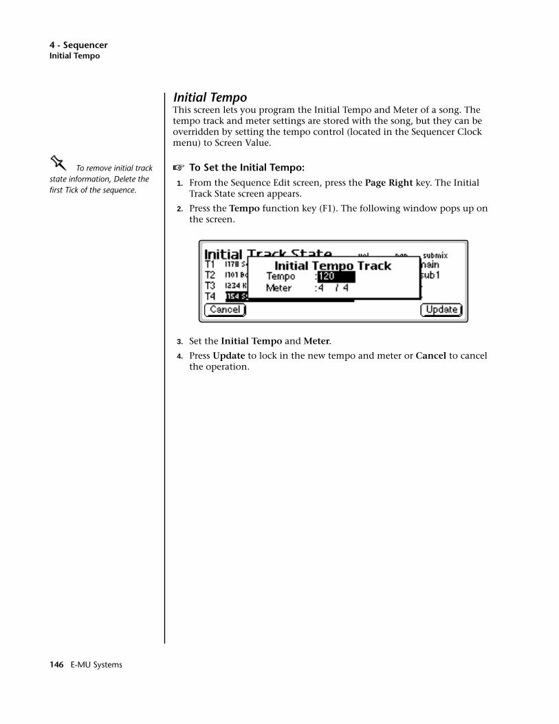
4 - SequencerInitial Tempo
Initial TempoThis screen lets you program the Initial Tempo and Meter of a song. The tempo track and meter settings are stored with the song, but they can be overridden by setting the tempo control (located in the Sequencer Clock menu) to Screen Value.
OOOO To remove initial track state information, Delete the first Tick of the sequence.
v To Set the Initial Tempo:1. From the Sequence Edit screen, press the Page Right key. The Initial
Track State screen appears.
2. Press the Tempo function key (F1). The following window pops up on the screen.
3. Set the Initial Tempo and Meter.
4. Press Update to lock in the new tempo and meter or Cancel to cancel the operation.
Cut/Copy
146 E-MU Systems
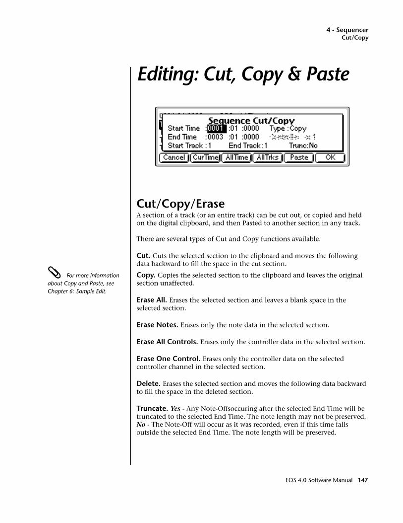
4 - SequencerCut/Copy
Editing: Cut, Copy & Paste
Cut/Copy/Erase A section of a track (or an entire track) can be cut out, or copied and held on the digital clipboard, and then Pasted to another section in any track.
There are several types of Cut and Copy functions available.
Cut. Cuts the selected section to the clipboard and moves the following data backward to fill the space in the cut section.
For more information about Copy and Paste, see Chapter 6: Sample Edit.
Copy. Copies the selected section to the clipboard and leaves the original section unaffected.
Erase All. Erases the selected section and leaves a blank space in the selected section.
Erase Notes. Erases only the note data in the selected section.
Erase All Controls. Erases only the controller data in the selected section.
Erase One Control. Erases only the controller data on the selected controller channel in the selected section.
Delete. Erases the selected section and moves the following data backward to fill the space in the deleted section.
Truncate. Yes - Any Note-Offsoccuring after the selected End Time will be truncated to the selected End Time. The note length may not be preserved. No - The Note-Off will occur as it was recorded, even if this time falls outside the selected End Time. The note length will be preserved.
EOS 4.0 Software Manual 147
4 - SequencerCut/Copy/Erase
v To Cut/Copy/Erase:1. From the Sequence Manage screen, press the Edit function key (F3).
2. Press the Utils function key (F1). A second row of function keys appears.
3. Press the Cut/Copy function key (F1). The Cut/Copy menu shown above appears.
4. Select the Start and End time in bars/beats/ticks using the cursor keys to select the field and the Data Entry Control or INC/DEC keys to change the selection.
• Press the All Time function key to select everything in the selected track(s).
• Press the function key to select the current location as the Start and End Times.
5. Select the range of tracks to be cut or copied.
• Press the All Trks function key to select all tracks.
6. Turn Truncate (note-off) On or Off.
7. If you have selected Erase One Control, select the controller number.
8. Press OK to proceed or Cancel to cancel the operation.
9. To go directly to the Paste operation, press Paste.
Note EraseEOS contains a quick and handy way to erase notes from a recorded track. Only one note can be erased at a time. If more than one note is held, the last note pressed will be used for the erase.
Conditions: For Note Erase to work…
• You must be in Record-Overdub mode.
• Loop Region must be On.
• The sequence must be on the second or subsequent loop.
The E will appear in the display ONLY if the above conditions are met.
v To Use Note Erase Mode:1. While playing back the sequence in Record-Overdub and Loop mode,
press and hold the Set/Shift key. An “E” appears in the Edit screen.
2. Play the note you wish to erase on the keyboard.
3. Release the note to stop erasing.
4. Release the Set key to go out of Erase mode.
148 E-MU Systems

4 - SequencerCut/Copy/Erase
Cut
Erase
Delete
CutSection
Start Time End Time
Result of CutCut Section is
Placed on Clipboard
StartTime
EndTime
Trash
Section is DUMPED!
BlankSection
StartTime
EndTime
Trash
Section is DUMPED!
BlankSection
EOS 4.0 Software Manual 149
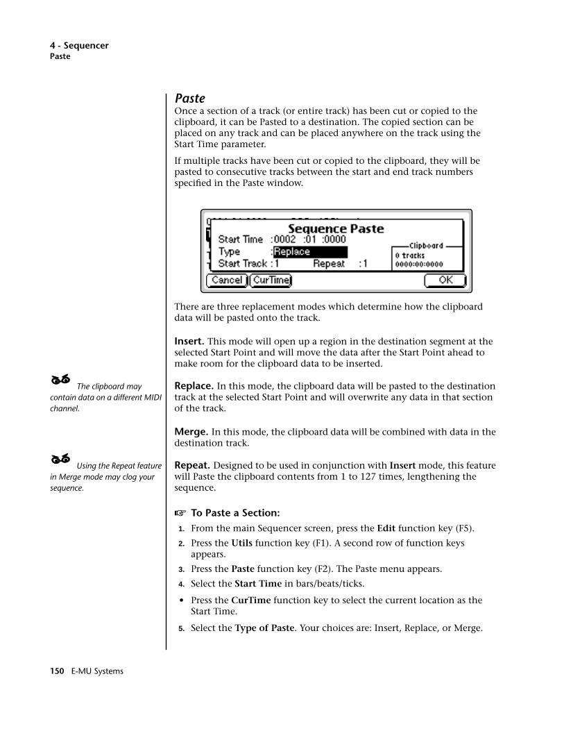
4 - SequencerPaste
PasteOnce a section of a track (or entire track) has been cut or copied to the clipboard, it can be Pasted to a destination. The copied section can be placed on any track and can be placed anywhere on the track using the Start Time parameter.
If multiple tracks have been cut or copied to the clipboard, they will be pasted to consecutive tracks between the start and end track numbers specified in the Paste window.
There are three replacement modes which determine how the clipboard data will be pasted onto the track.
Insert. This mode will open up a region in the destination segment at the selected Start Point and will move the data after the Start Point ahead to make room for the clipboard data to be inserted.
____ The clipboard may contain data on a different MIDI channel.
Replace. In this mode, the clipboard data will be pasted to the destination track at the selected Start Point and will overwrite any data in that section of the track.
Merge. In this mode, the clipboard data will be combined with data in the destination track.
____ Using the Repeat feature in Merge mode may clog your sequence.
Repeat. Designed to be used in conjunction with Insert mode, this feature will Paste the clipboard contents from 1 to 127 times, lengthening the sequence.
v To Paste a Section:1. From the main Sequencer screen, press the Edit function key (F5).
2. Press the Utils function key (F1). A second row of function keys appears.
3. Press the Paste function key (F2). The Paste menu appears.
4. Select the Start Time in bars/beats/ticks.
• Press the CurTime function key to select the current location as the Start Time.
5. Select the Type of Paste. Your choices are: Insert, Replace, or Merge.
150 E-MU Systems
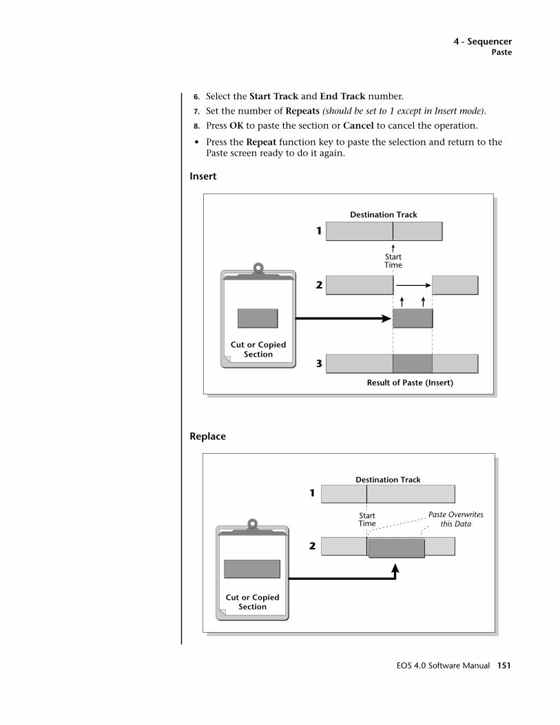
4 - SequencerPaste
6. Select the Start Track and End Track number.
7. Set the number of Repeats (should be set to 1 except in Insert mode).
8. Press OK to paste the section or Cancel to cancel the operation.
• Press the Repeat function key to paste the selection and return to the Paste screen ready to do it again.
Insert
Replace
Cut or CopiedSection
Destination Track
Result of Paste (Insert)
StartTime
1
2
3
Cut or CopiedSection
Destination Track
StartTime
1
2
Paste Overwritesthis Data
EOS 4.0 Software Manual 151
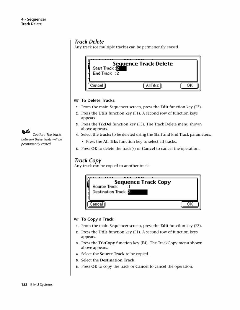
4 - SequencerTrack Delete
Track DeleteAny track (or multiple tracks) can be permanently erased.
v To Delete Tracks:1. From the main Sequencer screen, press the Edit function key (F3).
2. Press the Utils function key (F1). A second row of function keys appears.
3. Press the TrkDel function key (F3). The Track Delete menu shown above appears.
____ Caution: The tracks between these limits will be permanently erased.
4. Select the tracks to be deleted using the Start and End Track parameters.
• Press the All Trks function key to select all tracks.
5. Press OK to delete the track(s) or Cancel to cancel the operation.
Track CopyAny track can be copied to another track.
v To Copy a Track:1. From the main Sequencer screen, press the Edit function key (F3).
2. Press the Utils function key (F1). A second row of function keys appears.
3. Press the TrkCopy function key (F4). The TrackCopy menu shown above appears.
4. Select the Source Track to be copied.
5. Select the Destination Track.
6. Press OK to copy the track or Cancel to cancel the operation.
152 E-MU Systems
4 - SequencerUNDO! (REDO!)
UNDO! (REDO!)Have you ever wanted a time machine so that you could go back and undo a mistake? This function may be the next best thing. Whenever you perform any sequencer function, the original version of the sequence will be backed up. The sequence can be instantly restored to its previous state by pressing Undo.
REDO! reverses the Undo function and lets you compare the last and previous operations.
v To Restore a Sequence to its Previous State (UNDO!)
1. Press the Utils key from the sequencer edit level. A second row of function keys appears.
2. Press the UNDO! function key (F6). The sequence will be restored to the state before the last operation was performed.
v To Compare the Sequence with its Previous State (REDO!)1. Press the Utils key from the sequencer edit level. A second row of
function keys appears.
2. Press the UNDO! function key (F6). The sequence will be restored to the state before the last operation was performed.
3. Press the REDO! function key (F6) again. The processed sequence will be restored and the original sequence will be stored in the clipboard. You can continue switching back and forth until you decide which sample you want to keep.
Note: REDO! does not work with record functions.
EOS 4.0 Software Manual 153
4 - SequencerQuantize
Tools
The EOS Sequencer contains a host of special editing and filtering tools for modifying the sequence after it has been recorded.
Quantize. Adjusts the timing of notes so they fall exactly on the beat.
Transpose. Changes the key of a track section.
Velocity. Allows you to offset or scale velocity values within the selected section.
Channelize. Forces everything on a track to a single MIDI channel.
Extract. Separates individual channels from a multi-channel track.
v To Access the Sequencer Tools Menu:1. From the Sequencer Manage screen, press the Edit key (F5). The
Sequencer Edit screen appears.
2. Press the Tools function key (F2). Another row of function keys appears.
QuantizeThis function changes the timing of the notes in a sequence so that they fall exactly on the beat. This is useful when your playing was sloppy or to create drum tracks. Quantization can be applied in note values ranging from 1/4 notes to 1/64th note triplets.
____ Swing mode is disabled when the quantize amount is set to triplets.
Swing can be applied after recording to give a “bouncy” feel to your tracks. Swing quantizes the downbeats normally, but shifts the UPBEATS forward in time. A setting of 50% has no swing. Percentages from 60%, to 67% are normally used to get a nice “swing” feel.
Duration (when checked) will also quantize the note-off to the nearest note value. This changes the note duration which would make a quantized quarter note exactly one quarter note long.
154 E-MU Systems
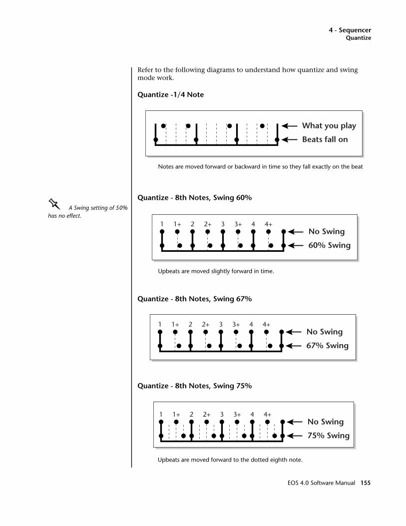
4 - SequencerQuantize
Refer to the following diagrams to understand how quantize and swing mode work.
Quantize -1/4 Note
Notes are moved forward or backward in time so they fall exactly on the beat
Quantize - 8th Notes, Swing 60%OOOO A Swing setting of 50% has no effect.
Upbeats are moved slightly forward in time.
Quantize - 8th Notes, Swing 67%
Quantize - 8th Notes, Swing 75%
Upbeats are moved forward to the dotted eighth note.
What you play
Beats fall on
No Swing
60% Swing
1 1+ 2 2+ 3 3+ 4 4+
No Swing
67% Swing
1 1+ 2 2+ 3 3+ 4 4+
No Swing
75% Swing
1 1+ 2 2+ 3 3+ 4 4+
EOS 4.0 Software Manual 155

4 - SequencerTranspose
v To Quantize Tracks:1. From the Sequencer Manage screen, press the Edit function key (F3).
2. Press the Tools function key (F2). A second row of function keys appears.
3. Press the Quantize function key (F1). The following screen appears.
4. Select the Start and End time in bars/beats/ticks using the cursor keys to select the field and the Data Entry Control or INC/DEC keys to change the selection.
• Press the All Time function key to select everything in the selected track(s).
5. Select the range of tracks to be quantized.
• Press the All Trks function key to select all tracks.
6. Select the Quantize Amount. The selected section can be quantized to: 1/4 notes, 1/4 note triplets, 1/8 notes, 1/8 note triplets, 1/16 notes, 1/16 note triplets, 1/32 notes, 1/32 note triplets, 1/64 notes or 1/64 note triplets.
7. Select the Swing Percentage if desired. (50% = Off).
8. Turn Duration On or Off as desired.
9. Press OK to Quantize or Cancel to cancel the operation.
TransposeThis function allows you to transpose a section of a track up or down in semitone increments. The range of transposition is ±128 semitones.
156 E-MU Systems
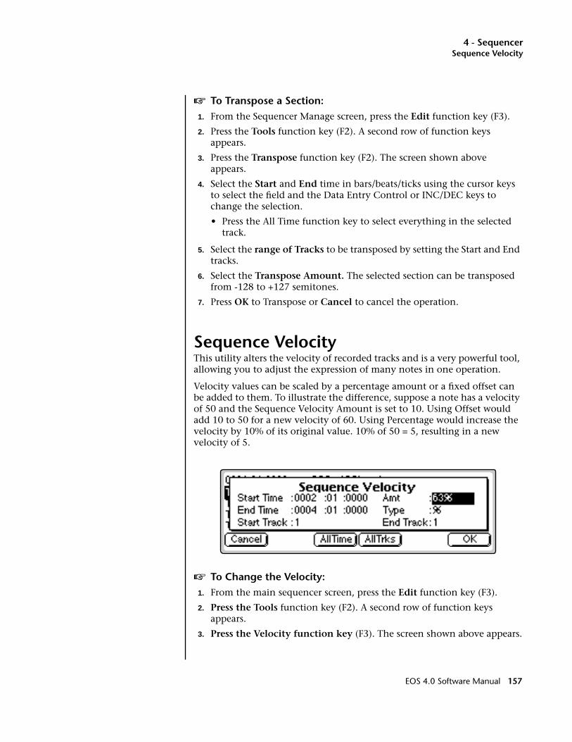
4 - SequencerSequence Velocity
v To Transpose a Section:1. From the Sequencer Manage screen, press the Edit function key (F3).
2. Press the Tools function key (F2). A second row of function keys appears.
3. Press the Transpose function key (F2). The screen shown above appears.
4. Select the Start and End time in bars/beats/ticks using the cursor keys to select the field and the Data Entry Control or INC/DEC keys to change the selection.
• Press the All Time function key to select everything in the selected track.
5. Select the range of Tracks to be transposed by setting the Start and End tracks.
6. Select the Transpose Amount. The selected section can be transposed from -128 to +127 semitones.
7. Press OK to Transpose or Cancel to cancel the operation.
Sequence VelocityThis utility alters the velocity of recorded tracks and is a very powerful tool, allowing you to adjust the expression of many notes in one operation.
Velocity values can be scaled by a percentage amount or a fixed offset can be added to them. To illustrate the difference, suppose a note has a velocity of 50 and the Sequence Velocity Amount is set to 10. Using Offset would add 10 to 50 for a new velocity of 60. Using Percentage would increase the velocity by 10% of its original value. 10% of 50 = 5, resulting in a new velocity of 5.
v To Change the Velocity:1. From the main sequencer screen, press the Edit function key (F3).
2. Press the Tools function key (F2). A second row of function keys appears.
3. Press the Velocity function key (F3). The screen shown above appears.
EOS 4.0 Software Manual 157
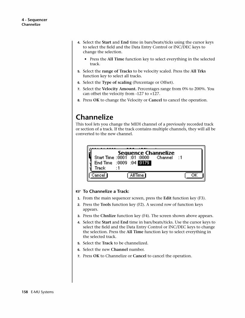
4 - SequencerChannelize
4. Select the Start and End time in bars/beats/ticks using the cursor keys to select the field and the Data Entry Control or INC/DEC keys to change the selection.
• Press the All Time function key to select everything in the selected track.
5. Select the range of Tracks to be velocity scaled. Press the All Trks function key to select all tracks.
6. Select the Type of scaling (Percentage or Offset).
7. Select the Velocity Amount. Percentages range from 0% to 200%. You can offset the velocity from -127 to +127.
8. Press OK to change the Velocity or Cancel to cancel the operation.
ChannelizeThis tool lets you change the MIDI channel of a previously recorded track or section of a track. If the track contains multiple channels, they will all be converted to the new channel.
v To Channelize a Track:1. From the main sequencer screen, press the Edit function key (F3).
2. Press the Tools function key (F2). A second row of function keys appears.
3. Press the Chnlize function key (F4). The screen shown above appears.
4. Select the Start and End time in bars/beats/ticks. Use the cursor keys to select the field and the Data Entry Control or INC/DEC keys to change the selection. Press the All Time function key to select everything in the selected track.
5. Select the Track to be channelized.
6. Select the new Channel number.
7. Press OK to Channelize or Cancel to cancel the operation.
158 E-MU Systems
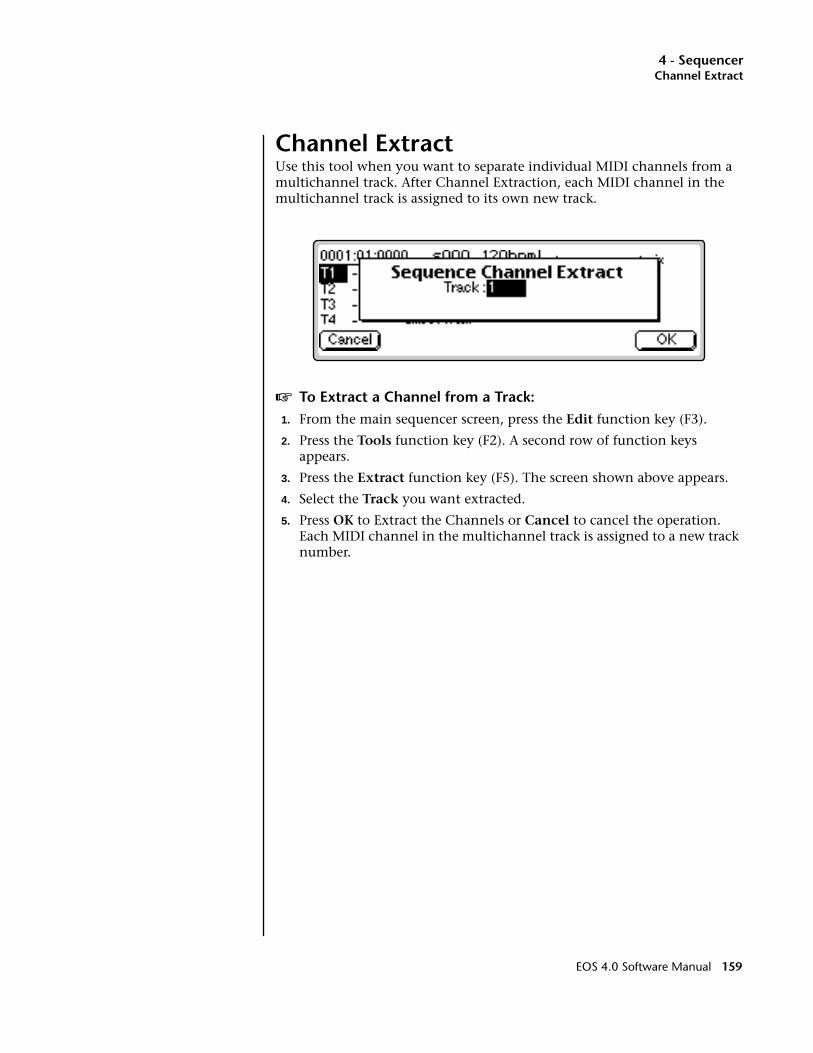
4 - SequencerChannel Extract
Channel ExtractUse this tool when you want to separate individual MIDI channels from a multichannel track. After Channel Extraction, each MIDI channel in the multichannel track is assigned to its own new track.
v To Extract a Channel from a Track:1. From the main sequencer screen, press the Edit function key (F3).
2. Press the Tools function key (F2). A second row of function keys appears.
3. Press the Extract function key (F5). The screen shown above appears.
4. Select the Track you want extracted.
5. Press OK to Extract the Channels or Cancel to cancel the operation. Each MIDI channel in the multichannel track is assigned to a new track number.
EOS 4.0 Software Manual 159
4 - SequencerSetup
Setup
The Setup menu contains mostly pre-sequence setup options such as the metronome, tempo, input quantize, sequence looping, etc. It also contains the MMC transport controls which can be used to control digital recorders and tape machines.
The Setup submodule contains the following functions:
Metronome . Sets the metronome to play internal sounds or external MIDI instruments or both. It also allows you to select a MIDI channel, preset, note number, beat value and two velocities for the metronome tick.
Tempo. Sets the tempo, meter, and clock type. You can also turn MIDI Clock Out on or off.
OOOO Use the Previous and Next Page keys to move back and forth through the Setup menus.
Input Quantize. Lets you quantize and add swing to tracks as they are recorded. This is very useful when creating percussion tracks.
Record Options. Recording can be set to start when the sequence starts, after a specified number of lead-in beats or on the first note played.
Looping. The sequence can be made to continuously loop or to stop at the end of the song.
Transport. The MMC transport allows you to control an external 48 track recorder from the EOS panel. The internal sequencer can also be controlled from this screen.
v To Access the Sequencer Setup Menu:1. From the Sequence Manage screen, press the Edit key. The Sequence
Edit screen appears.
2. Press the Setup function key (F3). Another row of function keys appears with the Sequencer Setup options.
160 E-MU Systems

4 - SequencerMetronome
MetronomeThe metronome provides an accurate beat for recording and is especially important when Quantizing since notes are quantized according to the metronome's clock.
This screen lets you choose the MIDI channel, preset, note number and accent velocity for the metronome sound.
Metronome . When in Internal mode, an onboard preset is used to produce the metronome sound. In External mode, the metronome generates a MIDI note to play the metronome note on an external synthe-sizer.
State . The metronome state determines whether the metronome will play when recording, in playback, or in record and play modes (both).
Preset. Selects the internal preset that the metronome uses when set to internal mode. A percussion instrument, such as a woodblock or rimshot, would be a good choice for the metronome sound, although any sound with a sharp attack can be used.
MIDI Note/Channel. Selects the note that will be used for the metronome sound. Select a MIDI channel if you are using an external MIDI instrument for the metronome sound.
Vel 1st/Other. This parameter allows you to set the velocity value for the first beat and subsequent beats in the measure. The first note is normally set to a higher velocity in order to identify the start of each measure. Note: The preset must have velocity programmed for this feature to work correctly.
Division. Division sets the meter for the metronome beats. Choose from Quarter notes, Eighth notes, or Sixteenth notes.
EOS 4.0 Software Manual 161

4 - SequencerSequence Clock
OOOO Use the Previous and Next Page keys to move back and forth through the Setup menus.
v To Set Up the Metronome:1. From the main sequencer screen, press the Edit function key.
2. Press the Setup function key (F3). A second row of function keys appears.
3. Press the Metro… function key (F1). The screen shown above appears. Note: The Preset screen is not accessible when External Metronome is selected.
4. Set the Metronome to Internal, External or Both.
5. Set the State. This sets the metronome to sound during record, playback or both.
6. Select the Preset if you are using the metronome in Internal mode.
7. Select the MIDI Note and MIDI Channel. As you change the note it will be transmitted so that you can hear which metronome sound you are selecting.
OOOO If the metronome preset has effects on it (and you don’t want effects):1. Copy the preset.2. Assign it to a Submix out with 0% effects.3. Save the Bank.4. Assign the Metronome to the new Preset.
8. Select the Note Velocity for the first note in the measure and for subse-quent notes. Usually the first note will be set to a higher velocity to accent the first note of the measure.
9. Set the Note Value in quarter notes, eighth notes or sixteenth note for the metronome.
10. Press Exit to lock in the Metronome settings and return to the Sequence Edit screen.
Sequence ClockThis screen sets the tempo and meter of a sequence. The sequencer tempo can be controlled by an internal or external clock. This screen also turns MIDI Clock Out on or off.
162 E-MU Systems

4 - SequencerSequence Clock
Clock Source. Determines if the sequencer clock is controlled by the internal or and external (MIDI) clock.
Tempo Control. Allows the tempo of a sequence to be controlled in one of three ways:
The Tempo and Meter screen are not accessible when Tempo Track is selected.
a. By the Tempo Track stored in the sequence. An initial tempo value is stored when you create a new sequence. Sequences imported from an external sequencer may have tempo changes within the song.
b. By the adjustable Screen Value tempo value shown in this display.
c. By an External Clock (MIDI).
OOOO The Arpeggiator and Sequencer use the SAME CLOCK.
Change the Arpeggiator clock to adjust the tempo of Flash sequences ……or Copy the Flash sequence to RAM, then adjust the tempo.
Tempo. Sets the tempo (speed) of the sequence and is adjustable from 20 beats per minute (bpm) to 240 bpm.
Meter. Sets the time signature of the song. The Meter setting is used by the metronome function to determine measures and beats.
MIDI Clock Out. Turns MIDI Clock Out on or off. Turn this feature on if you want to control an external MIDI device with the sequencer clock.
v To Set the Clock:1. From the main sequencer screen, press the Edit function key (F3).
2. Press the Setup function key (F3). A row of function keys appears.
3. Press the Clock function key (F2).
4. Select the Clock Source as internal or external clock.
5. Set the Tempo Control to Tempo Track, Screen Value or External Clock.
6. Set the desired Tempo (if Screen Value is selected)
7. Set the desired Meter (if Screen Value is selected). Any time signature can be programmed.
8. Turn MIDI Clock Out On or Off.
9. Press Exit to lock in the Clock settings and return to the Sequence Edit screen.
EOS 4.0 Software Manual 163
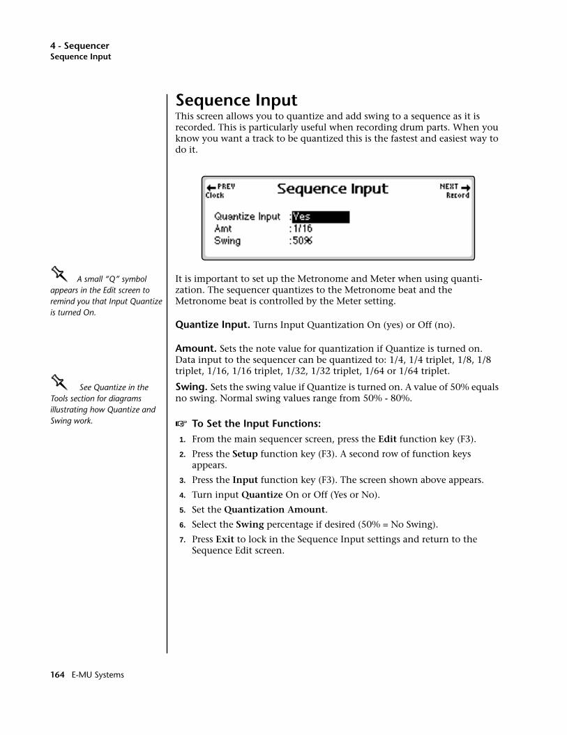
4 - SequencerSequence Input
Sequence InputThis screen allows you to quantize and add swing to a sequence as it is recorded. This is particularly useful when recording drum parts. When you know you want a track to be quantized this is the fastest and easiest way to do it.
OOOO A small “Q” symbol appears in the Edit screen to remind you that Input Quantize is turned On.
It is important to set up the Metronome and Meter when using quanti-zation. The sequencer quantizes to the Metronome beat and the Metronome beat is controlled by the Meter setting.
Quantize Input. Turns Input Quantization On (yes) or Off (no).
Amount. Sets the note value for quantization if Quantize is turned on. Data input to the sequencer can be quantized to: 1/4, 1/4 triplet, 1/8, 1/8 triplet, 1/16, 1/16 triplet, 1/32, 1/32 triplet, 1/64 or 1/64 triplet.
OOOO See Quantize in the Tools section for diagrams illustrating how Quantize and Swing work.
Swing. Sets the swing value if Quantize is turned on. A value of 50% equals no swing. Normal swing values range from 50% - 80%.
v To Set the Input Functions:1. From the main sequencer screen, press the Edit function key (F3).
2. Press the Setup function key (F3). A second row of function keys appears.
3. Press the Input function key (F3). The screen shown above appears.
4. Turn input Quantize On or Off (Yes or No).
5. Set the Quantization Amount.
6. Select the Swing percentage if desired (50% = No Swing).
7. Press Exit to lock in the Sequence Input settings and return to the Sequence Edit screen.
164 E-MU Systems

4 - SequencerSequence Record
Sequence RecordThese two functions determine when sequence recording begins.
Start Record - Button Press: Recording begins as soon as you press the Record and Play buttons and after the selected Count In beats (see below) have elapsed.
First Note: Recording begins as soon as you press any note on the keyboard. The Count In beat setting is ignored.
The Count In field is not available unless Button Press is selected.
Count InSets the number to metronome beats which will occur before actual recording will commence. The number of count In beats can be set from 1 to 127 or turned Off.
v To Set the Sequence Record Functions:1. From the main sequencer screen, press the Edit function key (F3).
2. Press the Setup function key (F3). A second row of function keys appears.
3. Press the Record function key (F4). The screen shown above appears.
4. Set Start Record for Button Press or First Note.
5. Set the number of Count In beats.
6. Press Exit to lock in the Sequence Record options and return to the Sequence Edit screen.
EOS 4.0 Software Manual 165
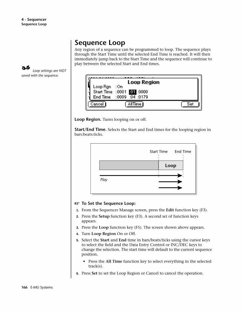
4 - SequencerSequence Loop
Sequence LoopAny region of a sequence can be programmed to loop. The sequence plays through the Start Time until the selected End Time is reached. It will then immediately jump back to the Start Time and the sequence will continue to play between the selected Start and End times.
____ Loop settings are NOT saved with the sequence.
Loop Region. Turns looping on or off.
Start/End Time. Selects the Start and End times for the looping region in bars:beats:ticks.
v To Set the Sequence Loop:1. From the Sequencer Manage screen, press the Edit function key (F3).
2. Press the Setup function key (F3). A second set of function keys appears.
3. Press the Loop function key (F5). The screen shown above appears.
4. Turn Loop Region On or Off.
5. Select the Start and End time in bars/beats/ticks using the cursor keys to select the field and the Data Entry Control or INC/DEC keys to change the selection. The start time will default to the current sequence position.
• Press the All Time function key to select everything in the selected track(s).
6. Press Set to set the Loop Region or Cancel to cancel the operation.
Loop
Play
Start Time End Time
166 E-MU Systems
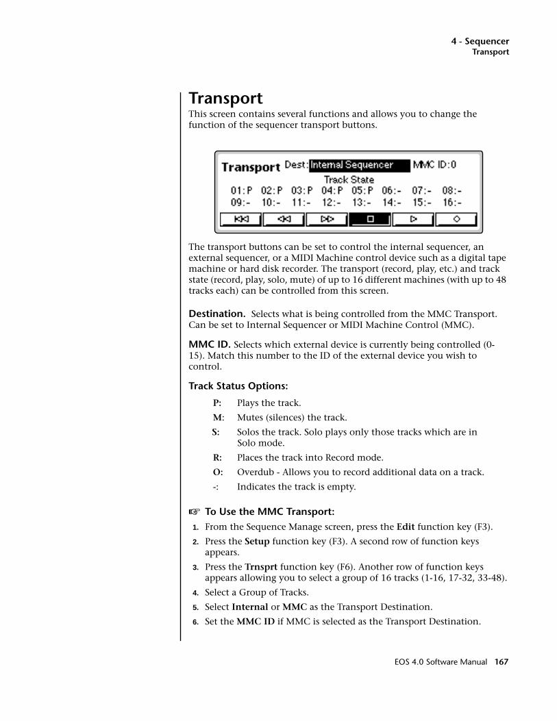
4 - SequencerTransport
TransportThis screen contains several functions and allows you to change the function of the sequencer transport buttons.
The transport buttons can be set to control the internal sequencer, an external sequencer, or a MIDI Machine control device such as a digital tape machine or hard disk recorder. The transport (record, play, etc.) and track state (record, play, solo, mute) of up to 16 different machines (with up to 48 tracks each) can be controlled from this screen.
Destination. Selects what is being controlled from the MMC Transport. Can be set to Internal Sequencer or MIDI Machine Control (MMC).
MMC ID. Selects which external device is currently being controlled (0-15). Match this number to the ID of the external device you wish to control.
Track Status Options:
P: Plays the track.
M: Mutes (silences) the track.
S: Solos the track. Solo plays only those tracks which are inSolo mode.
R: Places the track into Record mode.
O: Overdub - Allows you to record additional data on a track.
-: Indicates the track is empty.
v To Use the MMC Transport:1. From the Sequence Manage screen, press the Edit function key (F3).
2. Press the Setup function key (F3). A second row of function keys appears.
3. Press the Trnsprt function key (F6). Another row of function keys appears allowing you to select a group of 16 tracks (1-16, 17-32, 33-48).
4. Select a Group of Tracks.
5. Select Internal or MMC as the Transport Destination.
6. Set the MMC ID if MMC is selected as the Transport Destination.
EOS 4.0 Software Manual 167
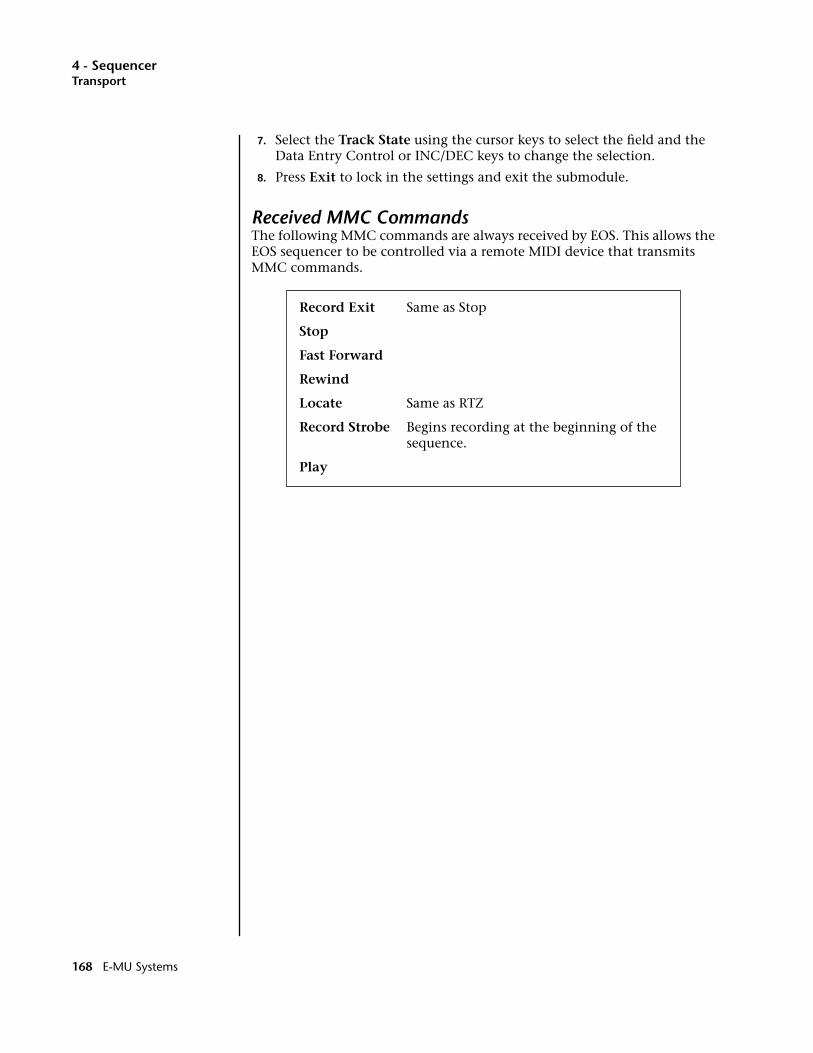
4 - SequencerTransport
7. Select the Track State using the cursor keys to select the field and the Data Entry Control or INC/DEC keys to change the selection.
8. Press Exit to lock in the settings and exit the submodule.
Received MMC CommandsThe following MMC commands are always received by EOS. This allows the EOS sequencer to be controlled via a remote MIDI device that transmits MMC commands.
Record Exit Same as Stop
Stop
Fast Forward
Rewind
Locate Same as RTZ
Record Strobe Begins recording at the beginning of the sequence.
Play
168 E-MU Systems
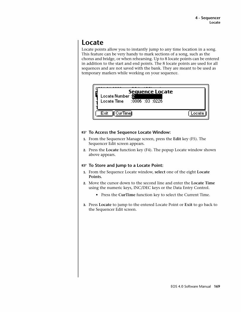
4 - SequencerLocate
LocateLocate points allow you to instantly jump to any time location in a song. This feature can be very handy to mark sections of a song, such as the chorus and bridge, or when rehearsing. Up to 8 locate points can be entered in addition to the start and end points. The 8 locate points are used for all sequences and are not saved with the bank. They are meant to be used as temporary markers while working on your sequence.
v To Access the Sequence Locate Window:1. From the Sequencer Manage screen, press the Edit key (F5). The
Sequencer Edit screen appears.
2. Press the Locate function key (F4). The popup Locate window shown above appears.
v To Store and Jump to a Locate Point:1. From the Sequence Locate window, select one of the eight Locate
Points.
2. Move the cursor down to the second line and enter the Locate Time using the numeric keys, INC/DEC keys or the Data Entry Control.
• Press the CurTime function key to select the Current Time.
3. Press Locate to jump to the entered Locate Point or Exit to go back to the Sequencer Edit screen.
EOS 4.0 Software Manual 169

4 - Sequencer
170 E-MU Systems

5 - Sample Manage
5Sample Manage
EOS 4.0 Software Manual 171

5 - Sample Manage
172 E-MU Systems

5 - Sample Manage
Overview
This “recording studio” module records sounds from the outside world into the bank. Features include adjustable preamp gain, variable threshold setting, and adjustable sample rate and length. Samples can also be named, copied, erased and automatically placed on the keyboard.
The Sample Manage menu contains six main sub menus:
Utilities. Contains the Erase, Copy, MIDI Sample Dump and Defragment functions.
Name. Allows you to name your samples.
New. The recording studio where sounds are sampled. This module also contains automatic DSP and setup functions such as auto-truncate, auto-normalize, auto-sample placement, auto looping.
Place. Allows you to assign the sample to any range of notes on the keyboard.
Export. Allows you to save an individual sample as a bank.
Info. Displays information on the selected sample.
EOS 4.0 Software Manual 173

5 - Sample ManageSample Utilities
Sample Utilities
The Sample Utilities menu contains several functions.
• Erase Sample
• Copy Sample
• Sample Dump
• Defragment Memory
Erase SampleThe Erase Sample operation erases individual samples from the bank.
v To Erase a Sample:1. Press the Sample Manage key. The LED illuminates and the main
screen appears.
2. Select the sample to be erased using the Data Entry Control, INC/DEC keys, or the numeric keypad.
3. Press the Utils function key (F1). A second row of function keys appears.
4. Press the Erase… function key (F1). A pop-up dialog box appears asking if you want to erase the selected sample.
5. Press OK to erase the sample. Another dialog box appears asking if you want to de-fragment the memory after erasing the sample.
6. Press Yes to defragment memory and erase the sample. Press No to erase the sample without defragmenting memory, or press Cancel to cancel the entire operation.
174 E-MU Systems
5 - Sample ManageSample Utilities
Copy Sample For more information about Defragmenting Memory, see“Defragment Memory” on page 177
Copying a sample duplicates the sample data so you can edit the copy and preserve the original sample. You can copy a sample to an empty sample number or overwrite an existing sample number.
v To Copy a Sample:1. Press the Sample Manage key. The LED illuminates and the main
screen appears.
2. Select the sampe you want to copy using the Data Entry Control or the INC/DEC keys. The Sample Clipboard can also be selected.
3. Press the Utils function key (F1). A second row of function keys appears.
4. Press the Copy… function key (F2). A pop-up dialog box appears asking you to select the destination sample location.
5. Select the destination sample location using the Data Entry Control, INC/DEC keys or the numeric keypad.
If you choose a destination that already contains a sample, the system asks you if you want to overwrite the existing sample before continuing.
6. Press OK to copy the sample or Cancel to cancel the operation.
Sample DumpMIDI Sample Dump lets you transfer sample data to and from the Emulator using the MIDI Sample Dump Standard. This is a way of transferring samples to and from other samplers. Although none of the preset param-eters are transferred, sample loop data is retained. If imported samples have loop problems such as “ticks or pops”, the Sample Integrity function (Sample Edit, Utilities) may be able to automatically repair them. Otherwise adjust the loop points.
Sample data can be transmitted with a word size of either 14 or 16 bits (some instruments require the use of the 14 bit word size). Use 14-bit mode for instruments that use 14 bits or less to transmit data 30% faster.
Before initiating MIDI Sample Dump, make sure that the MIDI cables are properly connected. A single MIDI cable (open-loop) is sufficient but the data transfers much faster if two MIDI cables are used (closed-loop). The closed-loop allows the two units to handshake and prevents idle time between each data packet. Connect the cables between the MIDI In and MIDI Out of both units.
In the MIDI Sample Dump Standard and in EOS, samples are assigned numbers and these numbers are maintained throughout the transfer. For example, sample #36 transferred from another device to the Emulator overwrites the existing sample #36 on the Emulator.
EOS 4.0 Software Manual 175
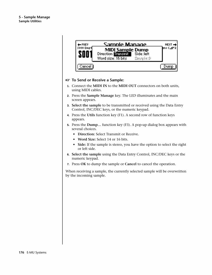
5 - Sample ManageSample Utilities
v To Send or Receive a Sample:1. Connect the MIDI IN to the MIDI OUT connectors on both units,
using MIDI cables.
2. Press the Sample Manage key. The LED illuminates and the main screen appears.
3. Select the sample to be transmitted or received using the Data Entry Control, INC/DEC keys, or the numeric keypad.
4. Press the Utils function key (F1). A second row of function keys appears.
5. Press the Dump… function key (F3). A pop-up dialog box appears with several choices.
• Direction: Select Transmit or Receive.
• Word Size: Select 14 or 16 bits.
• Side: If the sample is stereo, you have the option to select the right or left side.
6. Select the sample using the Data Entry Control, INC/DEC keys or the numeric keypad.
7. Press OK to dump the sample or Cancel to cancel the operation.
When receiving a sample, the currently selected sample will be overwritten by the incoming sample.
176 E-MU Systems
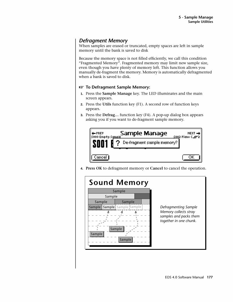
5 - Sample ManageSample Utilities
Defragment MemoryWhen samples are erased or truncated, empty spaces are left in sample memory until the bank is saved to disk
Because the memory space is not filled efficiently, we call this condition “Fragmented Memory”. Fragmented memory may limit new sample size, even though you have plenty of memory left. This function allows you manually de-fragment the memory. Memory is automatically defragmented when a bank is saved to disk.
v To Defragment Sample Memory:1. Press the Sample Manage key. The LED illuminates and the main
screen appears.
2. Press the Utils function key (F1). A second row of function keys appears.
3. Press the Defrag… function key (F4). A pop-up dialog box appears asking you if you want to de-fragment sample memory.
4. Press OK to defragment memory or Cancel to cancel the operation.
Defragmenting SampleMemory collects straysamples and packs themtogether in one chunk.
Sample
Sample
Sample SampleSample Sample
Sound Memory
Sample Sample
Sample
Sample
Sample
EOS 4.0 Software Manual 177
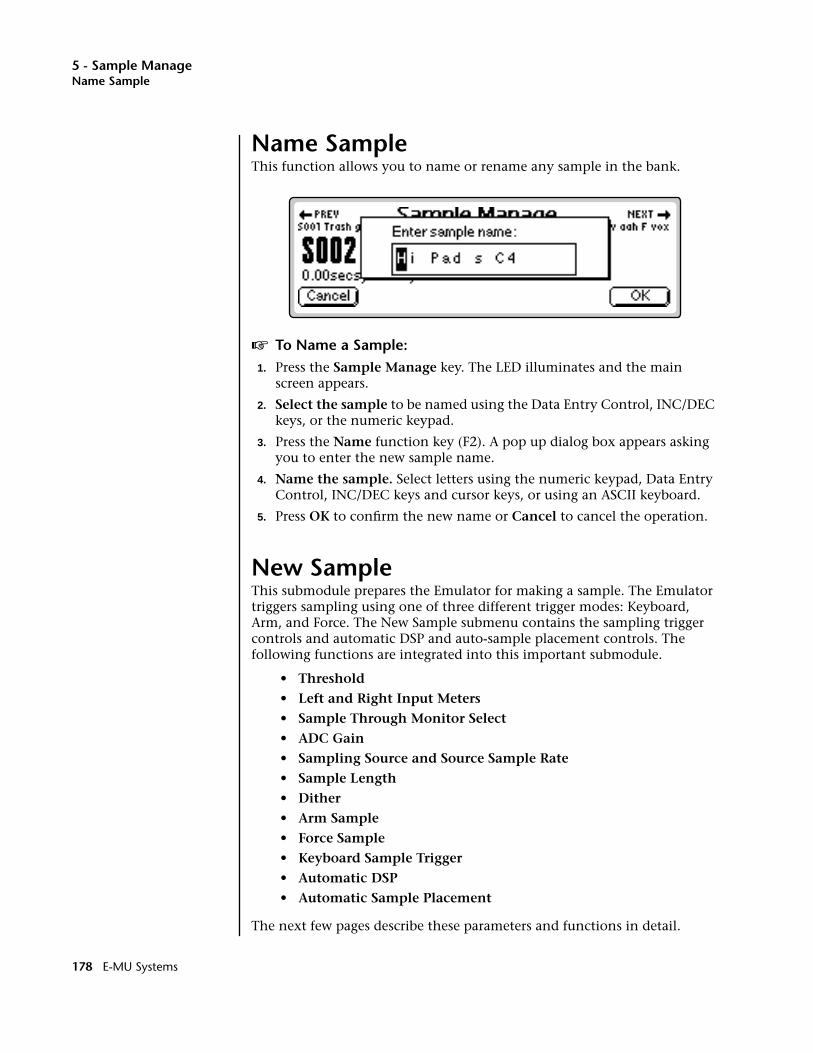
5 - Sample ManageName Sample
Name SampleThis function allows you to name or rename any sample in the bank.
v To Name a Sample:1. Press the Sample Manage key. The LED illuminates and the main
screen appears.
2. Select the sample to be named using the Data Entry Control, INC/DEC keys, or the numeric keypad.
3. Press the Name function key (F2). A pop up dialog box appears asking you to enter the new sample name.
4. Name the sample. Select letters using the numeric keypad, Data Entry Control, INC/DEC keys and cursor keys, or using an ASCII keyboard.
5. Press OK to confirm the new name or Cancel to cancel the operation.
New Sample This submodule prepares the Emulator for making a sample. The Emulator triggers sampling using one of three different trigger modes: Keyboard, Arm, and Force. The New Sample submenu contains the sampling trigger controls and automatic DSP and auto-sample placement controls. The following functions are integrated into this important submodule.
• Threshold
• Left and Right Input Meters
• Sample Through Monitor Select
• ADC Gain
• Sampling Source and Source Sample Rate
• Sample Length
• Dither
• Arm Sample
• Force Sample
• Keyboard Sample Trigger
• Automatic DSP
• Automatic Sample Placement
The next few pages describe these parameters and functions in detail.
178 E-MU Systems

5 - Sample ManageNew Sample
ThresholdIn the Arm Sampling mode, sampling begins when the input signal exceeds the threshold setting. The Threshold field defines this level. Set the sampling threshold high enough so that it is not triggered by background noise, but low enough that all of the signal is captured. Sampling is actually initiated just before the threshold is exceeded in order to preserve the attack transient of the sound. This is called pre-sampling. Pre-sampling times are preset depending on the sample rate; 12 mS at 44.1 kHz and above, 17 mS at 24 kHz and below (see Sampling Source & Rate for more information).
v To Set the Sample Threshold:1. Press the Sample Manage key. The LED illuminates and the main
screen appears.
2. Press the New function key (F3). The “Create Sample” display appears.
3. If it is not already there, move the cursor to “Threshold” using the cursor keys.
4. While observing the input signal on the VU meters, adjust the Sampling Threshold using the Data Entry Control, or INC/DEC keys.
5. Press the Exit key to return to the Sample Manage screen.
Input ChannelsSelect Left, Right or Both: The Input field determines which channels are On or Off and controls boththe analog and digital inputs (AES and ADAT). The input levels are displayed in the VU Meter (the VU meter is used to help set the ADC Gain). Use the INC/DEC keys or Data Entry Control to select Left, Right or Both channels. If sampling in mono, use the LEFT channel ONLY since the Threshold trigger only monitors the left channel.
Sampling Source & RateThe Source field defines the sampling source and the rate at which the information is sampled. It is important to use the lowest rate possible (to conserve memory) that is at least twice as high as the highest frequency component in the sound being sampled. If the sampling rate is too low, you will lose some of the high frequency information.
EOS 4.0 Software Manual 179
5 - Sample ManageNew Sample
Analog Sampling: Choose between 22.05 kHz, 24 kHz, 44.1 kHz or 48 kHz when using the analog inputs. The sample rate should be at least twice as high as the highest frequency component in the sound being sampled.
Ultra Series - Only two of the four sample rates will be shown at one time (22.05 kHz & 44.1 kHz) or (24 kHz & 48 kHz). To select a sample rate which is not currently displayed, press Master, Setup, In/Out , then change the Default Clock rate.
If an ADAT Optical card is installed, you will have four additional digital sampling source options:• ADAT in 1 and 2• ADAT in 3 and 4• ADAT in 5 and 6• ADAT in 7 and 8
Digital Sampling. Choose between 32 kHz, 44.1 kHz or 48 kHz when using the digital input. The display setting should match the sample rate of the incoming digital data, otherwise the Arm and Force Sample function keys cannot be selected. If a digital source is not connected, the AES clock indicator displays “no AES” and sampling is disabled.
A sample overload message is displayed if digital audio containing “Full Code” data (all 1's) is detected. This indicates that the input data has been clipped at some point. Full code data may distort in the Emulator because changing the pitch can cause a slight gain increase. If possible, reduce the level of the incoming digital data if you see an overload message.
____ 20 bit resampling is only available on the Ultra series Emulators.
Resampling: This function allows you to resample the main outputs as you are playing. Resampling lets you build up extremely dense sounds or record a sequence of notes to be played back with a single key. There are three resampling modes, 16 bit, 18 bit and 20 bit. Use 16 bit mode for monophonic or duophonic passages. The 18 and 20 bit modes give you more headroom when playing many notes at once. If clipping occurs, use a higher bit mode.
v To Set the Sample Source:1. Press the Sample Manage key. The LED illuminates and the main
screen appears.
2. Press the New function key (F3). The “Create Sample” screen appears.
3. Move the cursor to “Source” using the cursor keys.
4. Select the desired sampling source using the Data Entry Control or INC/DEC keys.
5. Press the Exit key to return to the Sample Manage screen.
DitherDither is a technique used in digital systems to improve audio performance by adding noise to the least significant data bits. Dither should be used whenever a digital number is converted to a smaller number (for instance when converting 20 bits to 16 bits).
EOS samples at 16 bit linear, so dither should be turned On when digitally sampling from a source that has more than 16 bits, for example when sampling a 24 bit AES signal or when sampling from a 20 bit ADAT machine. Dither can be either On or Off when analog sampling (the audio performance is the same).
180 E-MU Systems

5 - Sample ManageNew Sample
ADC GainADC stands for Analog-to-Digital Converter. The ADC Gain field defines the dynamic range for the sample. Setting too high an ADC gain may cause clipping. Set the analog sample level with the Data Entry Control or INC/DEC keys so that the left and right side meters indicate optimum sampling level. Play the sound to be sampled and observe the bar graph display. The signal level should be set so that the peak bar comes close to the extreme right side without actually reaching it. The gain is adjustable from -18 dB to +30 dB in 2 dB steps. This control has no effect on the digital input.
v To Set the ADC Gain:1. Press the Sample Manage key. The LED illuminates and the main
screen appears.
2. Press the New function key (F3). The following display appears.
3. Move the cursor to “ADC Gain” using the cursor keys.
4. Plug in a microphone or other sample source to view the left and right VU meters.
5. While monitoring the sound to be sampled on the VU meters, adjust the ADC Gain using the Data Entry Control or INC/DEC keys. Set the level so that the bars never quite reach the top of the meter range.
6. Press the Exit key to return to the Sample Manage screen or Arm or Force to begin sampling.
EOS 4.0 Software Manual 181
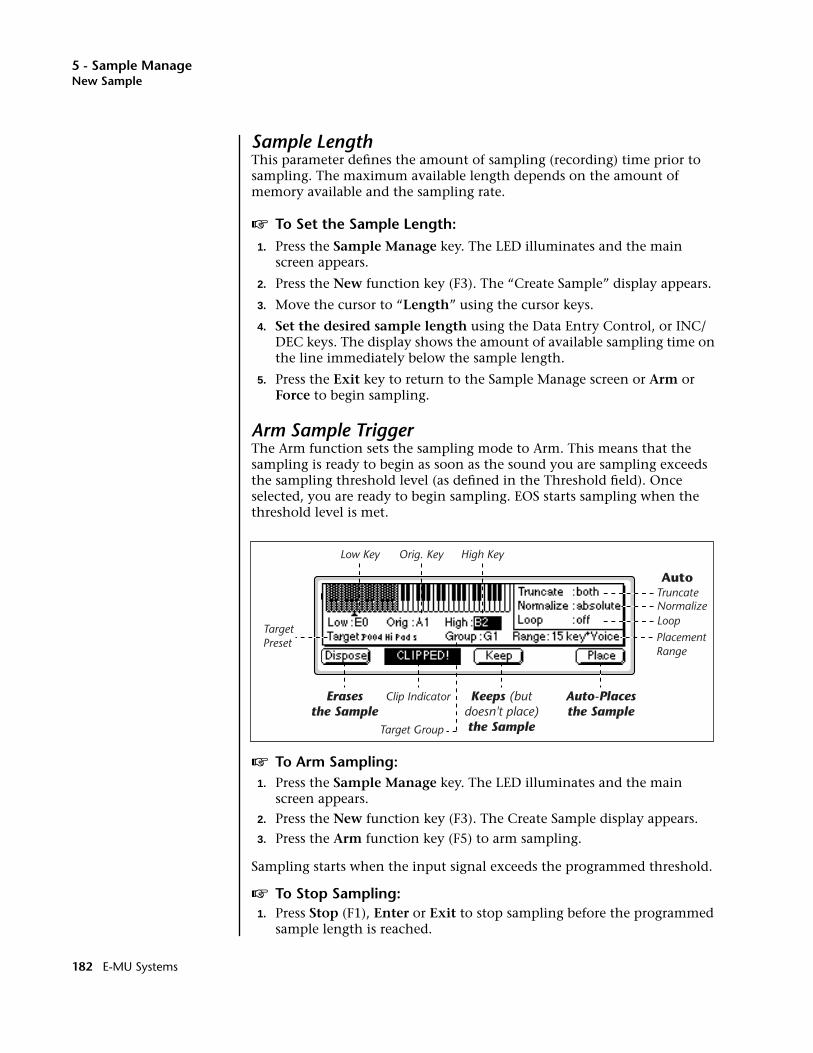
5 - Sample ManageNew Sample
Sample LengthThis parameter defines the amount of sampling (recording) time prior to sampling. The maximum available length depends on the amount of memory available and the sampling rate.
v To Set the Sample Length:1. Press the Sample Manage key. The LED illuminates and the main
screen appears.
2. Press the New function key (F3). The “Create Sample” display appears.
3. Move the cursor to “Length” using the cursor keys.
4. Set the desired sample length using the Data Entry Control, or INC/DEC keys. The display shows the amount of available sampling time on the line immediately below the sample length.
5. Press the Exit key to return to the Sample Manage screen or Arm or Force to begin sampling.
Arm Sample TriggerThe Arm function sets the sampling mode to Arm. This means that the sampling is ready to begin as soon as the sound you are sampling exceeds the sampling threshold level (as defined in the Threshold field). Once selected, you are ready to begin sampling. EOS starts sampling when the threshold level is met.
v To Arm Sampling:1. Press the Sample Manage key. The LED illuminates and the main
screen appears.
2. Press the New function key (F3). The Create Sample display appears.
3. Press the Arm function key (F5) to arm sampling.
Sampling starts when the input signal exceeds the programmed threshold.
v To Stop Sampling:1. Press Stop (F1), Enter or Exit to stop sampling before the programmed
sample length is reached.
Auto
Auto-Placesthe Sample
Keeps (butdoesn't place)the Sample
Erasesthe Sample
Truncate
Clip Indicator
TargetPreset
Target Group
NormalizeLoop
Low Key Orig. Key High Key
PlacementRange
182 E-MU Systems
5 - Sample ManageNew Sample
Force Sample TriggerThe Force sampling mode causes sampling to begin immediately (without waiting to exceed the threshold or pressing a key on the keyboard).
v To Force Sampling:1. Press the Sample Manage key. The LED illuminates and the main
screen appears.
2. Press the New function key (F3). The Create Sample display appears.
3. Press the Force function key (F6) to force sampling. Sampling will commence immediately.
v To Stop Sampling:1. Press Stop (F1), Enter or Exit to stop sampling before the programmed
sample length is reached.
Keyboard Sample TriggerThe Keyboard Trigger mode initiates sampling when you play a specified MIDI note. Sampling continues as long as the key is pressed and stops when the key is released (or the selected sample length is reached). Keyboard triggered sampling has several uses:
• Automatic “punch-in/punch-out” using a MIDI sequencer to initiate sampling via note-on/note-off events. This makes it easy to integrate “live” vocal or guitar parts into your MIDI sequences.
• Turns the Emulator into a digital multitrack recorder. Assign the lowest note to be the trigger key. Select resample. Sample length to maximum. Now press and hold the key while playing the keyboard with your left hand. Assign the sample to the trigger key, select another preset and record track two…and repeat the process. You have 64 or 128 tracks, depending on how many voices in your Emulator.
v To Trigger Sampling from a Key Depression:1. Press the Sample Manage key. The LED illuminates and the main
screen appears.
2. Press the New function key (F3). The Create Sample display appears.
3. Move the cursor to Trig Key and select the key using the Data Entry Control. INC/DEC keys or the keyboard.
4. Move the cursor to Chan and select the MIDI Channel for the trigger key using the Data Entry Control, or INC/DEC keys.
5. Press the Key function key (F4) to enable Key Sample Trigger. A pop-up dialog box appears informing you that sampling is armed.
v To Stop Sampling:1. Press Stop (F1), Enter or Exit to stop sampling before the programmed
sample length is reached.
EOS 4.0 Software Manual 183
5 - Sample ManageAutomatic Parameters
Monitor On/OffWith Monitor turned On, you can monitor the input source through the main outputs before, during and after sampling takes place. As a rule, you want to leave the Monitor on so that you can monitor your sample quality. On occasion there may be instances, such as a feedback loop in the mixing board, where you would want to turn sample monitor Off.
Automatic ParametersAfter sampling, the automatic parameters screen appears. You will perform certain sample processing functions on every sample you take. EOS can automatically perform these processes for you when you decide to keep it. After taking the sample you have three choices for what to do next: Dispose, Keep, and Place. This section describes these options and the automatic DSP operations performed on the sample. If clipping occurred during sampling, the display informs you at this time.
Dispose: Discards the sample and returns you to the New Sample menu.
Keep: Keeps the sample and performs the auto-DSP functions, but does not auto-place the sample. Returns you to the New Sample menu.
Place: Keeps the sample, performs the auto-DSP functions and auto-place functions, then returns you to the New Sample menu. When Place is selected, the sample is automatically placed in the target preset, group and range defined. See Auto-Placement Parameters.
Automatic Digital Signal Processing OperationsThe automatic DSP parameters are as follows:
Truncate: (Off, Start, End, Both). Automatically truncates the beginning, the end, or both the beginning and end of the sample. The point or points at which the sample is truncated is defined by the Zero Crossing Threshold parameter in the Master, Misc module.
Auto Normalize: (Off, Absolute, Relative) . Automatically increases the amplitude of a sample until the largest peak reaches 100% of full scale. Relative mode increases the amplitude of stereo samples until the largest peak of one side reaches 100%. Both sides maintain their proper amplitude relationship. Absolute mode increases the left and right samples to full level independently. Absolute and Relative have no effect when sampling in mono.
Auto Loop: (Off, Whole, 1/2, 1/2 + xfd, 1/3, 1/3 + xfd, 1/4, 1/4 + xfd, 1/8, 1/8 + xfd). This function automatically loops and autocorrelates the sample, then crossfade loops it if selected. Matching the loop length to the type of sample is important for getting the best results from auto loop. Ensemble sounds are notoriously hard to loop and are best looped manually.
184 E-MU Systems
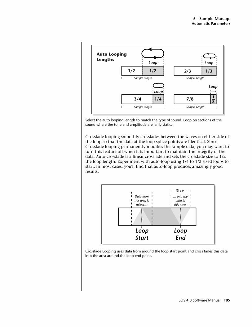
5 - Sample ManageAutomatic Parameters
Select the auto looping length to match the type of sound. Loop on sections of the sound where the tone and amplitude are fairly static.
Crossfade looping smoothly crossfades between the waves on either side of the loop so that the data at the loop splice points are identical. Since Crossfade looping permanently modifies the sample data, you may want to turn this feature off when it is important to maintain the integrity of the data. Auto-crossfade is a linear crossfade and sets the crossfade size to 1/2 the loop length. Experiment with auto-loop using 1/4 to 1/3 sized loops to start. In most cases, you'll find that auto-loop produces amazingly good results.
Crossfade Looping uses data from around the loop start point and cross fades this data into the area around the loop end point.
3/4 1/4
Loop
2/3 1/3
Loop
1/2 1/2
Loop
7/8
Loop
18
Sample Length Sample Length
Sample Length Sample Length
Auto LoopingLengths
LoopStart
LoopEnd
Data fromthis area ismixed…
… into thedata in
this area.
Size
EOS 4.0 Software Manual 185

5 - Sample ManageAutomatic Parameters
Auto-Placement ParametersThe auto-placement parameters define which preset, group, and range of keys to place the sample on the keyboard when the sample is placed automatically.
____ Be sure to change the target preset when resampling or you may place the sample into the same preset you are sampling from.
Target Preset: Selects the preset to which the sample will be auto-placed.
Target Group: Selects a group number for the sample.
Range: Samples will be placed on the keyboard according to the selected placement range, beginning with the original key. The original key can be changed at any time to change the placement of samples.
The choices for range are:
OOOO Multisample voices contain multiple samples. The Expand function in the Preset Edit menu creates individual voices for each sample in a Multisample.
• Auto* Multisample: This function places consecutive samples into a multisample voice at the original key you select from your MIDI keyboard. As you take additional samples, the low and high keys are adjusted in order to fit the new samples onto the keyboard.You don't ever have to set the low and high keys! Simply define the original pitch and you're finished. Samples are automatically named using the name of the preset appended with the original key name (i.e. Strings C1).
Auto* Multisample: The first sample is placed over the entire keyboard. When a new sample is taken, the low and high keys are automatically adjusted to accommodate the new sample.
Sample01
LowKey
HighKey
OriginalKey (S01)
OriginalKey (S02)
OriginalKey (S01)
Sample01
Sample02
186 E-MU Systems
5 - Sample ManageAutomatic Parameters
• White Key* Voice: A new sample will be placed on the lowest avail-able white key beginning at the original key you select (C1 is the default starting key). Each new sample will create a new voice.
• 1 Key* Voice: A new sample will be placed on the lowest available white or black key beginning at the original key you select (C1 is the default starting key). Each new sample will create a new voice.
• 2-24 Key* Voice: New samples will be placed over a keyboard range consisting of the number of keys selected. You can select the start-ing key by manually setting the original key (C1 is the default start-ing key). Each new sample will create a new voice.
v To Create an Auto-Multisample:This function works especially well for sampling other synthesizers.
1. Press the Sample Manage key. The LED illuminates and the main screen appears.
2. Press the New function key (F3). The Create Sample display appears.
3. Set up the sampling parameters such as sample length, sample source.
4. Take the sample. The auto-placement screen appears.
5. Press the Original Key on your MIDI keyboard.
6. Set Truncate to Both, Normalize to Relative, Loop to 1/4 + xfade.
7. Set Range to auto* Multisample.
8. Set the Target Preset to an empty location.
9. Press Place. You will be asked to name the preset (if it was empty).
10. Name the preset and press OK. EOS performs the DSP functions, then auto-places the sample.
11. If you wish to take additional samples do so now. Simply define the original key using your MIDI keyboard then press Place after taking each sample.
EOS 4.0 Software Manual 187

5 - Sample ManagePlace Sample
Place SampleAfter sampling, a sample is automatically assigned to its own voice. This function allows you to place the voice (and the sample) If you chose to keep it and now want to place it, or if you placed the sample and later want to place it somewhere else.
v To Place a Sample:1. Press the Sample Manage key. The LED illuminates and the main
screen appears.
2. Select the sample to be placed using the Data Entry Control, INC/DEC keys, or the numeric keypad.
3. Press the Place function key (F4). The screen shown above appears.
4. The sample can also be assigned a group number at this stage as a convenience. Use the Data Entry Control or INC/DEC keys to change the group number if desired.
5. Set the Original Key and the High and Low keys for the voice. Use the Cursor keys or function keys to select the parameter and the INC/DEC keys, your MIDI keyboard or the Data Entry Control to change the key range.
6. Press Place to confirm placement or Exit to cancel the operation.
188 E-MU Systems
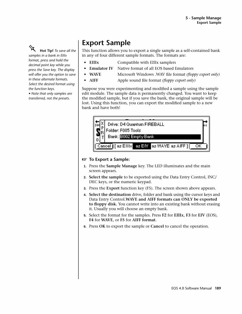
5 - Sample ManageExport Sample
Export SampleOOOO Hot Tip! To save all the samples in a bank in EIIIx format, press and hold the decimal point key while you press the Save key. The display will offer you the option to save in these alternate formats. Select the desired format using the function keys.• Note that only samples are transferred, not the presets.
This function allows you to export a single sample as a self-contained bank in any of four different sample formats. The formats are:
• EIIIx Compatible with EIIIx samplers
• Emulator IV Native format of all EOS based Emulators
• WAVE Microsoft Windows .WAV file format (floppy export only)
• AIFF Apple sound file format (floppy export only)
Suppose you were experimenting and modified a sample using the sample edit module. The sample data is permanently changed. You want to keep the modified sample, but if you save the bank, the original sample will be lost. Using this function, you can export the modified sample to a new bank and have both!
v To Export a Sample:1. Press the Sample Manage key. The LED illuminates and the main
screen appears.
2. Select the sample to be exported using the Data Entry Control, INC/DEC keys, or the numeric keypad.
3. Press the Export function key (F5). The screen shown above appears.
4. Select the destination drive, folder and bank using the cursor keys and Data Entry Control.WAVE and AIFF formats can ONLY be exported to floppy disk. You cannot write into an existing bank without erasing it. Usually you will choose an empty bank.
5. Select the format for the samples. Press F2 for EIIIx, F3 for EIV (EOS), F4 for WAVE, or F5 for AIFF format.
6. Press OK to export the sample or Cancel to cancel the operation.
EOS 4.0 Software Manual 189

5 - Sample ManageGet Info
Get InfoThis function displays a sample's size in number of samples and length in seconds. It also lists the amount of memory remaining.
v To Get Information about a Sample:1. Press the Sample Manage key. The LED illuminates and the main
screen appears.
2. Select the desired sample using the Data Entry Control, INC/DEC keys, or the numeric keypad.
3. Press the Info… function key (F6). A pop-up window appears with information about the sample.
4. Press the OK function key to return to the main Sample Manage screen.
190 E-MU Systems
6 - Sample Edit
6Sample Edit
EOS 4.0 Software Manual 191

6 - Sample Edit
192 E-MU Systems
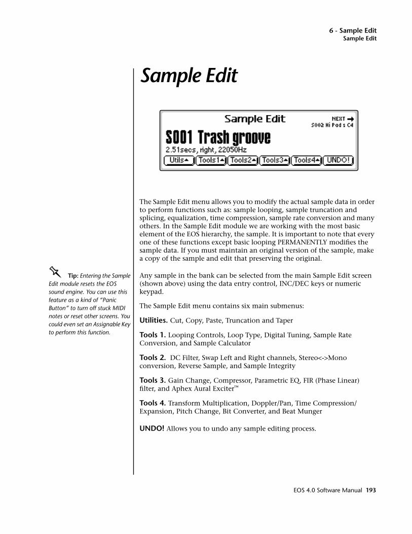
6 - Sample EditSample Edit
Sample Edit
The Sample Edit menu allows you to modify the actual sample data in order to perform functions such as: sample looping, sample truncation and splicing, equalization, time compression, sample rate conversion and many others. In the Sample Edit module we are working with the most basic element of the EOS hierarchy, the sample. It is important to note that every one of these functions except basic looping PERMANENTLY modifies the sample data. If you must maintain an original version of the sample, make a copy of the sample and edit that preserving the original.
OOOO Tip: Entering the Sample Edit module resets the EOS sound engine. You can use this feature as a kind of “Panic Button” to turn off stuck MIDI notes or reset other screens. You could even set an Assignable Key to perform this function.
Any sample in the bank can be selected from the main Sample Edit screen (shown above) using the data entry control, INC/DEC keys or numeric keypad.
The Sample Edit menu contains six main submenus:
Utilities. Cut, Copy, Paste, Truncation and Taper
Tools 1. Looping Controls, Loop Type, Digital Tuning, Sample Rate Conversion, and Sample Calculator
Tools 2. DC Filter, Swap Left and Right channels, Stereo<->Mono conversion, Reverse Sample, and Sample Integrity
Tools 3. Gain Change, Compressor, Parametric EQ, FIR (Phase Linear) filter, and Aphex Aural Exciter™
Tools 4. Transform Multiplication, Doppler/Pan, Time Compression/Expansion, Pitch Change, Bit Converter, and Beat Munger
UNDO! Allows you to undo any sample editing process.
EOS 4.0 Software Manual 193

6 - Sample EditBackground: The Scrub Wheel
Background: The Scrub WheelThe Scrub Wheel is a great function that allows you to use the controller's pitch wheel in many Sample Edit functions to quickly move through a sound, similar in concept to rocking the reels of a reel-to-reel tape recorder. The scrub wheel makes it easy to locate a particular section of a sound because you are able to hear the sound as you move through it.
To use the scrub wheel, move the pitch wheel of your MIDI keyboard while in a Sample Edit function such as Truncation or Looping. If the pitch wheel is moved slightly forward, the sound will play slowly through its length. If the wheel is pushed forward all the way, the sound will play through faster. If the wheel is moved backwards (towards you) the sound will play backwards through the sound. The scrub wheel operates like the accelerator on your car: the harder you press it, the faster it goes.
SCRUB WHEEL. Move the wheel slightly to advance slowly through the sound. Move the wheel more to advance quickly through the sound.
FAST
SLOWSTOP
SLOW
FAST
FORWARD
REVERSE
194 E-MU Systems

6 - Sample EditBackground: Using Cut, Copy, Paste and Undo
Background: Using Cut, Copy, Paste and UndoImagine a printout of a sample. Now imagine that you have a pair of scissors capable of cutting a piece out of that sample (or a copy of that piece if you don’t want to affect the original), as well as a clipboard to neatly hold the cut or copied piece. Now imagine that you can either perfectly insert the clipboard contents at any given point in any sample, or mix the clipboard contents in with any sample, starting at any designated point. The Emulator can do all this, and all electronically. Auto Correlation and Crossfade functions are also provided for seamless transitions between the cut, copied, and pasted parts.
Undo and RedoDuring several sample edit operations such as cut, paste, and sample rate conversion, the sample being processed will automatically be backed up and stored on the main hard disk drive. If you do not like the results of the processing, you can call up the Undo function, and restore the original sample from the main drive. (Ah, if only life itself were so simple.) Best of all, the processed sample will now move onto the main drive. Thus, if you decide you liked the processed version better after all, you can actually undo the undo. (Redo.)
Sample 00
CLIPBOARD DATA. The clipboard will retaindata until replaced by other data to becopied, cut, or backed up. This occurs withseveral operations where you want to be ableto undo an action that doesn't work.
EOS 4.0 Software Manual 195
6 - Sample EditBackground: About Looping
Insufficient Hard Disk Drive MemoryThe display will inform you if there is not enough memory to back up a sample onto the hard disk drive. You then have two choices: either free up some additional memory by erasing banks on the hard disk drive, or call up the Undo function and disable the backup process. Of course, if backup is disabled, you will not be able to undo an operation.
Typical ApplicationsTypical cut/copy/paste applications would be to splice the beginning of one sample to the end of another, or to mix two samples together to conserve memory. (Do this by copying an entire sample, then pasting it at the beginning of the second sample using the mix option.) You can splice an attack transient on to a synthesizer waveform loop to produce realistic sounds that take up virtually no memory, or take out a pop or click in a sample. Another possi-bility is, flanging and chorusing. Paste (mix) a sample to itself, offset from the beginning by a few hundred samples or so, to thicken up the sound.
Background: About LoopingSampling is the process of storing sounds in digital memory. Since each individual sample (not the complete sample, but each element of the sample) requires one memory slot, memory requirements increase if you sample long sounds or use high sampling rates.
How Looping WorksLooping is a technique that can extend a sound’s length without using lots of memory. It is based on the fact that many sounds start off with a complex attack transient, then settle down to a comparatively steady sound. Listen carefully to a plucked guitar string. The first part of the sound consists of a complex mixture of pick noise and several harmonics; after a while, the string decays down to a pretty steady repetitive waveform.
Since the latter part of the waveform is repetitive, there is no need to waste memory sampling several seconds of it. Instead, you can mark off a loop of the repetitive section, and play that looped section for as long as the key is held down. After playing to the end of the loop, the sound jumps back to the beginning of the loop and play through the loop again. This process repeats until you release the key playing back the sample.
Auto CorrelationFirst of all, just what does auto correlation mean? Auto correlation simply means automatic correlation or comparison. The computer analyzes the signal around the loop points you have specified and then moves the start or end point of the loop until it finds a section of the wave that closely matches the section around the start point. If the Fix Size parameter is On, the Start point of the loop is adjusted. If Fix Size is Off, the End point in the loop is adjusted. Auto correlation may be used again and again with the computer moving the analysis window slightly each time to try to zero in on the optimum loop.
196 E-MU Systems
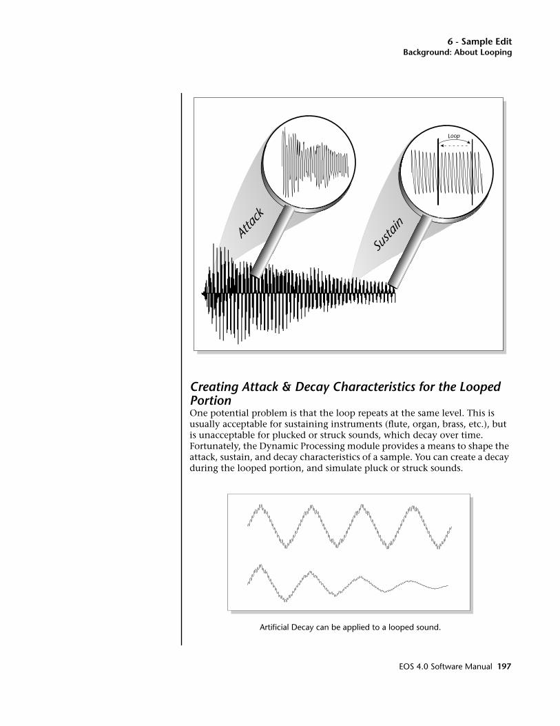
6 - Sample EditBackground: About Looping
Creating Attack & Decay Characteristics for the Looped PortionOne potential problem is that the loop repeats at the same level. This is usually acceptable for sustaining instruments (flute, organ, brass, etc.), but is unacceptable for plucked or struck sounds, which decay over time. Fortunately, the Dynamic Processing module provides a means to shape the attack, sustain, and decay characteristics of a sample. You can create a decay during the looped portion, and simulate pluck or struck sounds.
Artificial Decay can be applied to a looped sound.
Atta
ck
Susta
in
Loop
EOS 4.0 Software Manual 197
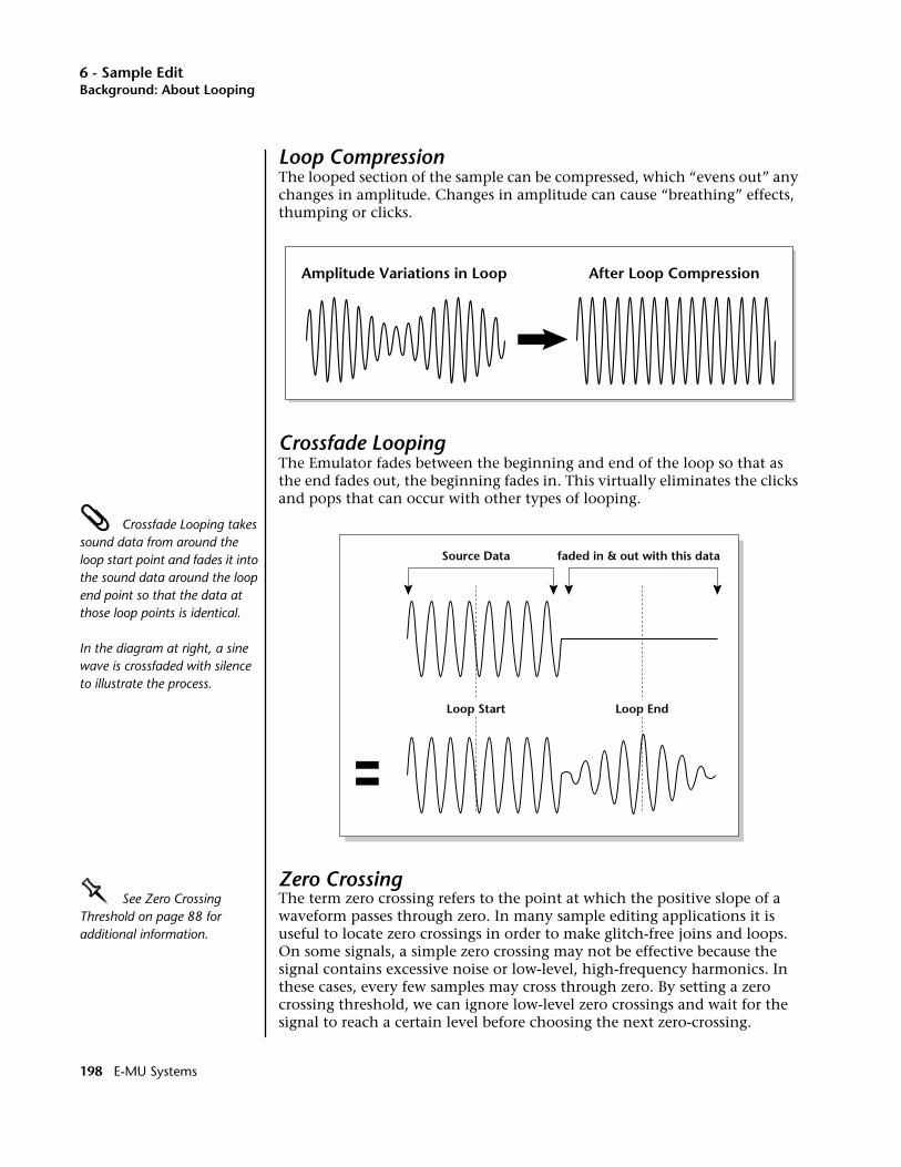
6 - Sample EditBackground: About Looping
Loop CompressionThe looped section of the sample can be compressed, which “evens out” any changes in amplitude. Changes in amplitude can cause “breathing” effects, thumping or clicks.
Crossfade LoopingThe Emulator fades between the beginning and end of the loop so that as the end fades out, the beginning fades in. This virtually eliminates the clicks and pops that can occur with other types of looping.
Crossfade Looping takes sound data from around the loop start point and fades it into the sound data around the loop end point so that the data at those loop points is identical.
In the diagram at right, a sine wave is crossfaded with silence to illustrate the process.
Zero CrossingOOOO See Zero Crossing Threshold on page 88 for additional information.
The term zero crossing refers to the point at which the positive slope of a waveform passes through zero. In many sample editing applications it is useful to locate zero crossings in order to make glitch-free joins and loops. On some signals, a simple zero crossing may not be effective because the signal contains excessive noise or low-level, high-frequency harmonics. In these cases, every few samples may cross through zero. By setting a zero crossing threshold, we can ignore low-level zero crossings and wait for the signal to reach a certain level before choosing the next zero-crossing.
Amplitude Variations in Loop After Loop Compression
Source Data faded in & out with this data
Loop Start Loop End
198 E-MU Systems
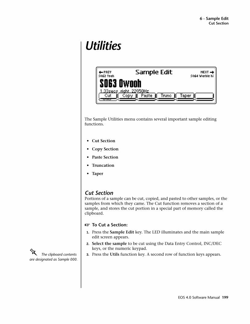
6 - Sample EditCut Section
Utilities
The Sample Utilities menu contains several important sample editing functions.
• Cut Section
• Copy Section
• Paste Section
• Truncation
• Taper
Cut SectionPortions of a sample can be cut, copied, and pasted to other samples, or the samples from which they came. The Cut function removes a section of a sample, and stores the cut portion in a special part of memory called the clipboard.
v To Cut a Section:
1. Press the Sample Edit key. The LED illuminates and the main sample edit screen appears.
2. Select the sample to be cut using the Data Entry Control, INC/DEC keys, or the numeric keypad.
OOOO The clipboard contents are designated as Sample 000.
3. Press the Utils function key. A second row of function keys appears.
EOS 4.0 Software Manual 199
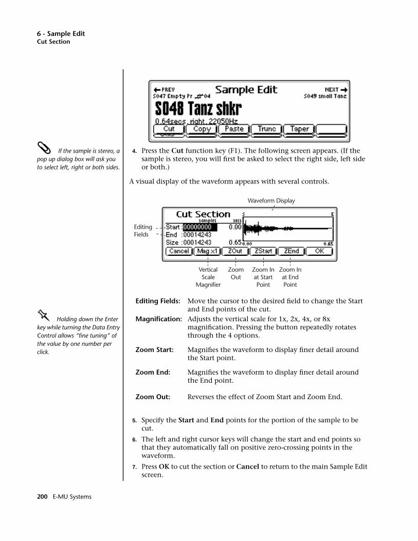
6 - Sample EditCut Section
If the sample is stereo, a pop up dialog box will ask you to select left, right or both sides.
4. Press the Cut function key (F1). The following screen appears. (If the sample is stereo, you will first be asked to select the right side, left side or both.)
A visual display of the waveform appears with several controls.
Editing Fields: Move the cursor to the desired field to change the Start and End points of the cut.
OOOO Holding down the Enter key while turning the Data Entry Control allows “fine tuning” of the value by one number per click.
Magnification: Adjusts the vertical scale for 1x, 2x, 4x, or 8x magnification. Pressing the button repeatedly rotates through the 4 options.
Zoom Start: Magnifies the waveform to display finer detail around the Start point.
Zoom End: Magnifies the waveform to display finer detail around the End point.
Zoom Out: Reverses the effect of Zoom Start and Zoom End.
5. Specify the Start and End points for the portion of the sample to be cut.
6. The left and right cursor keys will change the start and end points so that they automatically fall on positive zero-crossing points in the waveform.
7. Press OK to cut the section or Cancel to return to the main Sample Edit screen.
Waveform Display
EditingFields
VerticalScale
Magnifier
ZoomOut
Zoom Inat StartPoint
Zoom Inat EndPoint
200 E-MU Systems

6 - Sample EditCopy Section
8. If you are not happy with the resulting cut or want to compare before and after, press the Undo function key (F6).
Copy SectionPortions of a sample can be cut, copied, and pasted to other samples, or the samples from which they came. The Copy function allows you to duplicate a section of a sample, and store that duplicate in a special part of memory called the clipboard.
v To Copy a Section:
1. Press the Sample Edit key. The LED illuminates and the main sample edit screen appears.
2. Select the sample to be copied using the Data Entry Control, INC/DEC keys, or the numeric keypad.
If the sample is stereo, a pop up dialog box will ask you to select left, right or both sides.
3. Press the Utils function key (F1). A second row of function keys appears.
4. Press the Copy function key (F2). The Copy Section screen appears. (If the sample is stereo, you will first be asked to select the right side, left side or both.)
• The Copy Section display is identical to the display in Cut Section. See Cut Section for a full description of the controls.
OOOO The clipboard contents are designated as Sample 000.
5. Specify the Start and End points for the portion of the sample to be copied using the Data Entry Control, left/right cursor keys, INC/DEC keys or the numeric keypad.
6. Press OK to cut the section or Cancel to return to the main Sample Edit screen.
Sample 00
Cut Start Cut End
Result of CutCut Region is
Placed on Clipboard
EOS 4.0 Software Manual 201
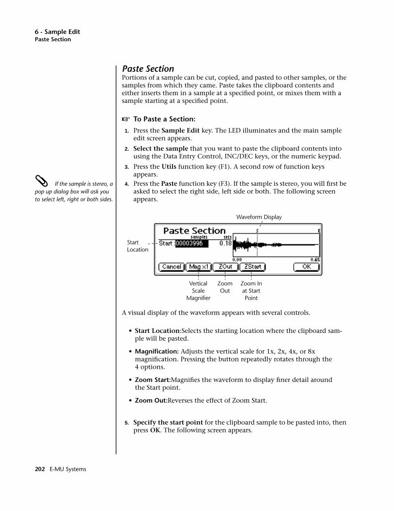
6 - Sample EditPaste Section
Paste SectionPortions of a sample can be cut, copied, and pasted to other samples, or the samples from which they came. Paste takes the clipboard contents and either inserts them in a sample at a specified point, or mixes them with a sample starting at a specified point.
v To Paste a Section:
1. Press the Sample Edit key. The LED illuminates and the main sample edit screen appears.
2. Select the sample that you want to paste the clipboard contents into using the Data Entry Control, INC/DEC keys, or the numeric keypad.
3. Press the Utils function key (F1). A second row of function keys appears.
If the sample is stereo, a pop up dialog box will ask you to select left, right or both sides.
4. Press the Paste function key (F3). If the sample is stereo, you will first be asked to select the right side, left side or both. The following screen appears.
A visual display of the waveform appears with several controls.
• Start Location:Selects the starting location where the clipboard sam-ple will be pasted.
• Magnification: Adjusts the vertical scale for 1x, 2x, 4x, or 8x magnification. Pressing the button repeatedly rotates through the 4 options.
• Zoom Start:Magnifies the waveform to display finer detail around the Start point.
• Zoom Out:Reverses the effect of Zoom Start.
5. Specify the start point for the clipboard sample to be pasted into, then press OK. The following screen appears.
Waveform Display
StartLocation
VerticalScale
Magnifier
ZoomOut
Zoom Inat StartPoint
202 E-MU Systems
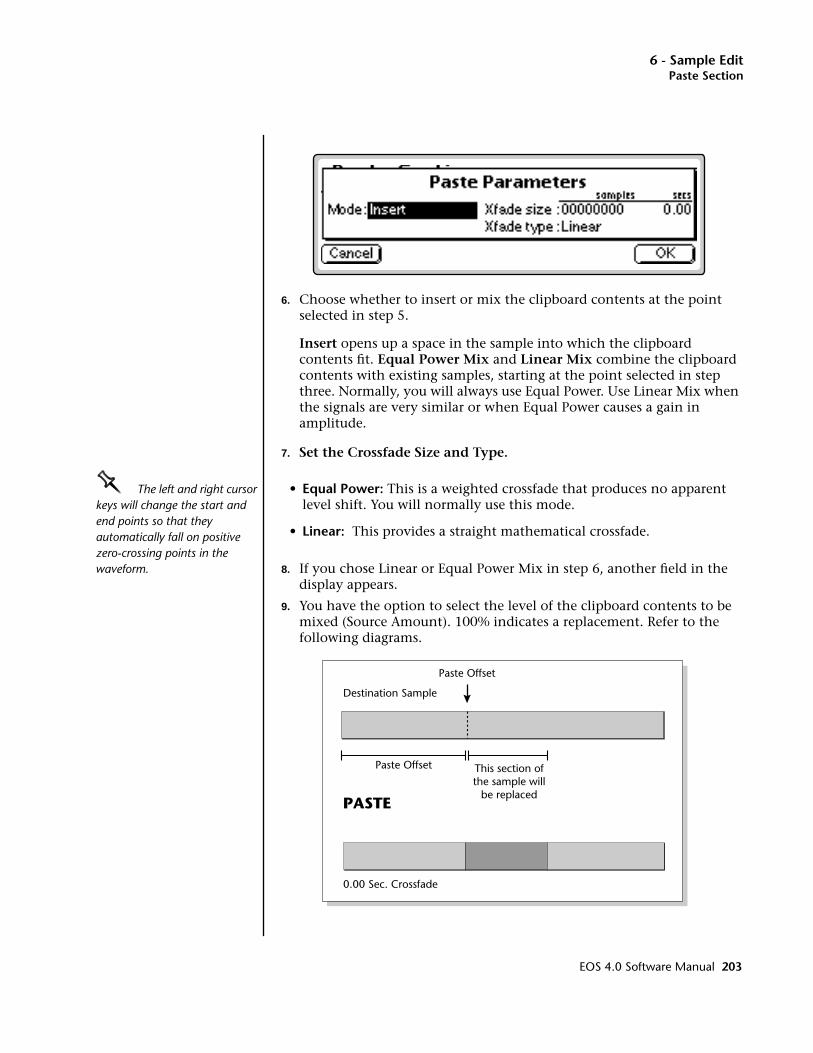
6 - Sample EditPaste Section
6. Choose whether to insert or mix the clipboard contents at the point selected in step 5.
Insert opens up a space in the sample into which the clipboard contents fit. Equal Power Mix and Linear Mix combine the clipboard contents with existing samples, starting at the point selected in step three. Normally, you will always use Equal Power. Use Linear Mix when the signals are very similar or when Equal Power causes a gain in amplitude.
7. Set the Crossfade Size and Type.
OOOO The left and right cursor keys will change the start and end points so that they automatically fall on positive zero-crossing points in the waveform.
• Equal Power: This is a weighted crossfade that produces no apparent level shift. You will normally use this mode.
• Linear: This provides a straight mathematical crossfade.
8. If you chose Linear or Equal Power Mix in step 6, another field in the display appears.
9. You have the option to select the level of the clipboard contents to be mixed (Source Amount). 100% indicates a replacement. Refer to the following diagrams.
Paste Offset
Destination Sample
PASTE
This section ofthe sample will
be replaced
0.00 Sec. Crossfade
Paste Offset
EOS 4.0 Software Manual 203
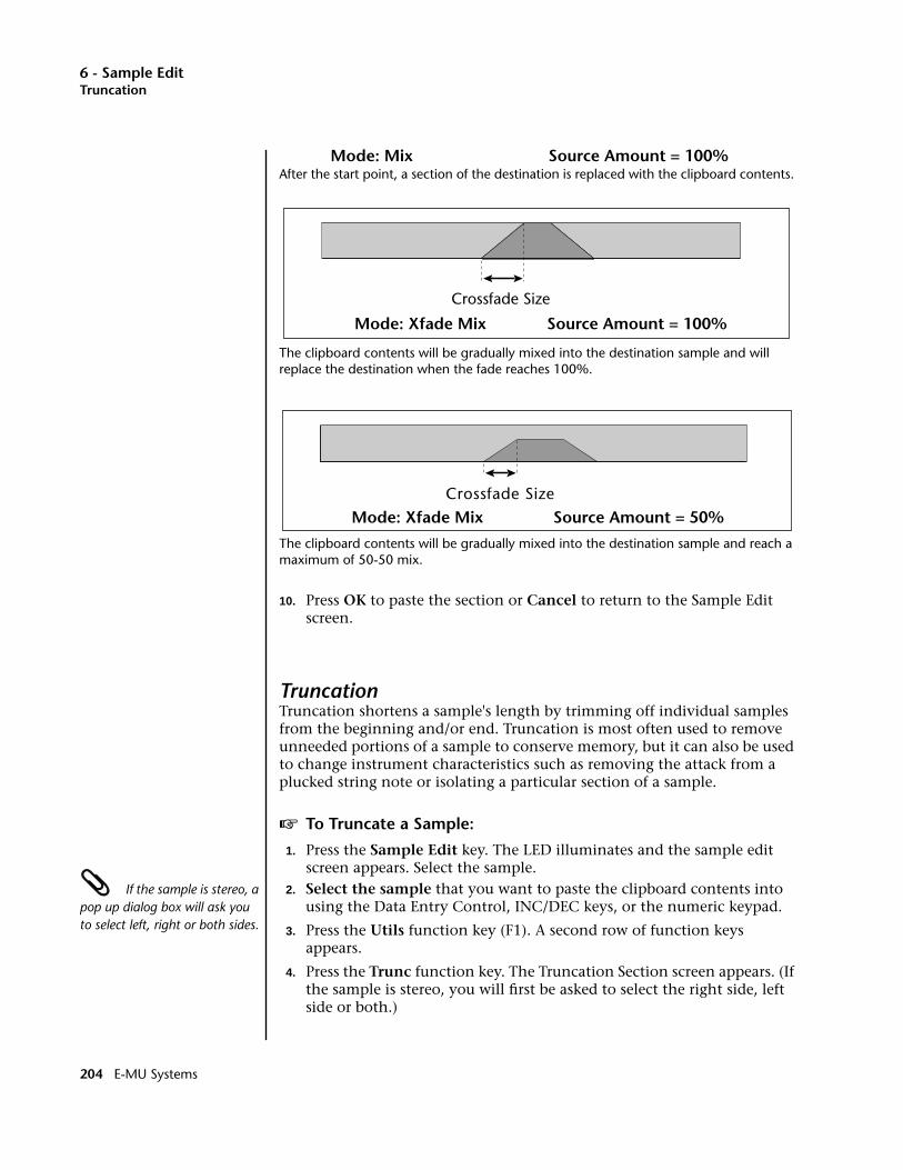
6 - Sample EditTruncation
Mode: Mix Source Amount = 100%After the start point, a section of the destination is replaced with the clipboard contents.
The clipboard contents will be gradually mixed into the destination sample and will replace the destination when the fade reaches 100%.
The clipboard contents will be gradually mixed into the destination sample and reach a maximum of 50-50 mix.
10. Press OK to paste the section or Cancel to return to the Sample Edit screen.
TruncationTruncation shortens a sample's length by trimming off individual samples from the beginning and/or end. Truncation is most often used to remove unneeded portions of a sample to conserve memory, but it can also be used to change instrument characteristics such as removing the attack from a plucked string note or isolating a particular section of a sample.
v To Truncate a Sample:
1. Press the Sample Edit key. The LED illuminates and the sample edit screen appears. Select the sample.
If the sample is stereo, a pop up dialog box will ask you to select left, right or both sides.
2. Select the sample that you want to paste the clipboard contents into using the Data Entry Control, INC/DEC keys, or the numeric keypad.
3. Press the Utils function key (F1). A second row of function keys appears.
4. Press the Trunc function key. The Truncation Section screen appears. (If the sample is stereo, you will first be asked to select the right side, left side or both.)
Crossfade Size
Mode: Xfade Mix Source Amount = 100%
Crossfade SizeMode: Xfade Mix Source Amount = 50%
204 E-MU Systems
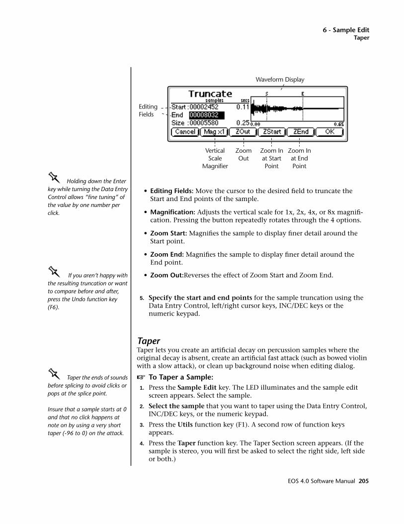
6 - Sample EditTaper
OOOO Holding down the Enter key while turning the Data Entry Control allows “fine tuning” of the value by one number per click.
• Editing Fields: Move the cursor to the desired field to truncate the Start and End points of the sample.
• Magnification: Adjusts the vertical scale for 1x, 2x, 4x, or 8x magnifi-cation. Pressing the button repeatedly rotates through the 4 options.
• Zoom Start: Magnifies the sample to display finer detail around the Start point.
• Zoom End: Magnifies the sample to display finer detail around the End point.
OOOO If you aren’t happy with the resulting truncation or want to compare before and after, press the Undo function key (F6).
• Zoom Out:Reverses the effect of Zoom Start and Zoom End.
5. Specify the start and end points for the sample truncation using the Data Entry Control, left/right cursor keys, INC/DEC keys or the numeric keypad.
TaperTaper lets you create an artificial decay on percussion samples where the original decay is absent, create an artificial fast attack (such as bowed violin with a slow attack), or clean up background noise when editing dialog.
OOOO Taper the ends of sounds before splicing to avoid clicks or pops at the splice point.
Insure that a sample starts at 0 and that no click happens at note on by using a very short taper (-96 to 0) on the attack.
v To Taper a Sample:1. Press the Sample Edit key. The LED illuminates and the sample edit
screen appears. Select the sample.
2. Select the sample that you want to taper using the Data Entry Control, INC/DEC keys, or the numeric keypad.
3. Press the Utils function key (F1). A second row of function keys appears.
4. Press the Taper function key. The Taper Section screen appears. (If the sample is stereo, you will first be asked to select the right side, left side or both.)
Waveform Display
EditingFields
VerticalScale
Magnifier
ZoomOut
Zoom Inat StartPoint
Zoom Inat EndPoint
EOS 4.0 Software Manual 205

6 - Sample EditTaper
5. Specify the Start and End points for the portion of the sample to be tapered using the Data Entry Control, left/right cursor keys, INC/DEC keys or the numeric keypad.
The Taper display is identical to the display in Truncate. See Truncate for a full description of the controls.
6. Press OK to continue on to the next page of options or Cancel to cancel the operation.
OOOO The left and right cursor buttons will change the start and end points so that they fall on positive zero-crossing points in the waveform.
Several more tapering parameters are shown.
• Start Amount:This is the amount of attenuation or gain applied at the start of the selected section. Variable from -96 dB to +96 dB.
• End Amount:This is the amount of attenuation or gain applied at the end of the selected section. Variable from -96 dB to +96 dB.
• Type: Selects the type of curve: Linear, Exponential 1, Exponential 2. Exponential 3.
• Truncate: (After Taper) Discards any information after the taper end point in order to conserve memory.
7. Specify the taper parameters using the Data Entry Control, or the INC/DEC keys.
8. Press OK to taper the sample or Cancel to cancel the operation.
206 E-MU Systems

6 - Sample EditLoop
Tools 1
This submodule contains the basic digital processing tools listed below.
Looping: Looping repeats a section of the sample continuously as long as the key is held. This allows a short sample to sustain indefinitely.
Digital Tuning: Digitally retunes a sample within a range of ±1 octave.
Sample Rate Convert: Converts the sample to any sample rate between 7000 Hz and 200000 Hz.
Sample Calculator:.A handy utility to help you calculate the sample rates needed for perfect single-cycle loops.
LoopIf you have a difficult time finding good loop points, the Auto Correlation function can assist you. If Auto Correlation doesn’t produce acceptable results, the beginning and end of a loop can be crossfaded to help mask loop discontinuities. For more information, see “About Looping” at the beginning of this section.
• Adjust the zero crossing threshold according to the type of wave you are looping. A setting of -96 dB is most sensitive and can be used for finding the start point of a sound. Settings closer to -30 dB are less sensitive and suited for finding zero-crossings in complex waves. See Zero Crossing Threshold on page 88 for more information.
v To Set the Loop Points
1. Press the Sample Edit key. The LED illuminates and the main sample edit screen appears.
2. Select the sample that you want to loop using the Data Entry Control, INC/DEC keys, or the numeric keypad.
EOS 4.0 Software Manual 207

6 - Sample EditLoop
3. Press the Tools 1 function key (F2). Another row of function keys appears.
4. Press the Loop function key (F1). The following screen appears.
• Editing Fields: Move the cursor to the desired field to change the Start, End or Size of the loop. The Loop Start Loop End and Loop Size parameters can be independently changed. Press the Fix Size button to keep the loop size constant.
Fix Size Button: When the box is checked, the Loop Size parameter is locked at the current value. This is handy when you have found the right size loop and are looking for a better start point.
Fix Size is very useful for creating groove loops and single cycle loops.
• Auto Correlate: Analyzes the waveform to find likely loop points. With Fix Size On, the Start Point of the Loop is adjusted.
OOOO Looping is an art which takes a bit of practice to learn. Auto Correlate works best when you have already found a fairly good loop point by ear. Several different types of tools are provided to help you loop almost any sound.
With Fix Size Off, the End Point is adjusted.
• Zoom In: Magnifies the waveform to display fine detail and brings up the loop window.
• Zoom Out: Reverses the effect of Zoom In and displays the entire sample.
When you Zoom In on the waveform, the Loop Window appears. The loop window magnifies the splice point of the loop as shown by the bracketed area in the diagrams below.
The line in the center of the magnified loop window shows the exact splice point of the loop. You can use the left and right cursor keys to select zero-crossings for the loop start.
Waveform Display
EditingFields
FixLoop Size
ZoomOut
AutoCorrelate
Zoom In
208 E-MU Systems
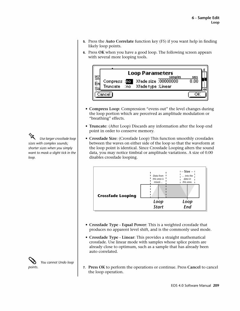
6 - Sample EditLoop
5. Press the Auto Correlate function key (F5) if you want help in finding likely loop points.
6. Press OK when you have a good loop. The following screen appears with several more looping tools.
• Compress Loop: Compression “evens out” the level changes during the loop portion which are perceived as amplitude modulation or “breathing” effects.
• Truncate: (After Loop) Discards any information after the loop end point in order to conserve memory.
OOOO Use larger crossfade loop sizes with complex sounds; shorter sizes when you simply want to mask a slight tick in the loop.
• Crossfade Size: (Crossfade Loop) This function smoothly crossfades between the waves on either side of the loop so that the waveform at the loop point is identical. Since Crossfade Looping alters the sound data, you may notice timbral or amplitude variations. A size of 0.00 disables crossfade looping.
• Crossfade Type - Equal Power: This is a weighted crossfade that produces no apparent level shift, and is the commonly used mode.
• Crossfade Type - Linear: This provides a straight mathematical crossfade. Use linear mode with samples whose splice points are already close to optimum, such as a sample that has already been auto correlated.
You cannot Undo loop points. 7. Press OK to perform the operations or continue. Press Cancel to cancel
the loop operation.
LoopStart
LoopEnd
Data fromthis area ismixed…
… into thedata in
this area.
Size
Crossfade Looping
EOS 4.0 Software Manual 209
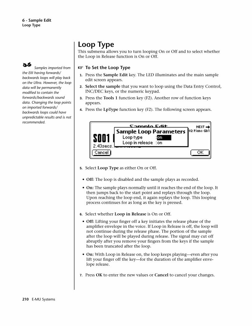
6 - Sample EditLoop Type
Loop TypeThis submenu allows you to turn looping On or Off and to select whether the Loop in Release function is On or Off.
____ Samples imported from the EIII having forwards/backwards loops will play back on the Ultra. However, the loop data will be permanently modified to contain the forwards/backwards sound data. Changing the loop points on imported forwards/backwards loops could have unpredictable results and is not recommended.
v To Set the Loop Type
1. Press the Sample Edit key. The LED illuminates and the main sample edit screen appears.
2. Select the sample that you want to loop using the Data Entry Control, INC/DEC keys, or the numeric keypad.
3. Press the Tools 1 function key (F2). Another row of function keys appears.
4. Press the LpType function key (F2). The following screen appears.
5. Select Loop Type as either On or Off.
• Off: The loop is disabled and the sample plays as recorded.
• On: The sample plays normally until it reaches the end of the loop. It then jumps back to the start point and replays through the loop. Upon reaching the loop end, it again replays the loop. This looping process continues for as long as the key is pressed.
6. Select whether Loop in Release is On or Off.
• Off: Lifting your finger off a key initiates the release phase of the amplifier envelope in the voice. If Loop in Release is off, the loop will not continue during the release phase. The portion of the sample after the loop will be played during release. The signal may cut off abruptly after you remove your fingers from the keys if the sample has been truncated after the loop.
• On: With Loop in Release on, the loop keeps playing—even after you lift your finger off the key—for the duration of the amplifier enve-lope release.
7. Press OK to enter the new values or Cancel to cancel your changes.
210 E-MU Systems
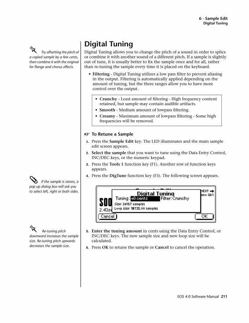
6 - Sample EditDigital Tuning
Digital TuningOOOO Try offsetting the pitch of a copied sample by a few cents, then combine it with the original for flange and chorus effects.
Digital Tuning allows you to change the pitch of a sound in order to splice or combine it with another sound of a different pitch. If a sample is slightly out of tune, it is usually better to fix the sample once and for all, rather than re-tuning the sample every time it is placed on the keyboard.
• Filtering - Digital Tuning utilizes a low pass filter to prevent aliasing in the output. Filtering is automatically applied depending on the amount of tuning, but the three ranges allow you to have more control over the output.
• Crunchy - Least amount of filtering - High frequency content retained, but sample may contain audible artifacts.
• Smooth - Medium amount of lowpass filtering.
• Creamy - Maximum amount of lowpass filtering - Some high frequencies will be removed.
v To Retune a Sample
1. Press the Sample Edit key. The LED illuminates and the main sample edit screen appears.
2. Select the sample that you want to tune using the Data Entry Control, INC/DEC keys, or the numeric keypad.
3. Press the Tools 1 function key (F1). Another row of function keys appears.
4. Press the DigTune function key (F3). The following screen appears. If the sample is stereo, a pop up dialog box will ask you to select left, right or both sides.
OOOO Re-tuning pitch downward increases the sample size. Re-tuning pitch upwards decreases the sample size.
5. Enter the tuning amount in cents using the Data Entry Control, or INC/DEC keys. The new sample size and new loop size will be calculated.
6. Press OK to retune the sample or Cancel to cancel the operation.
EOS 4.0 Software Manual 211
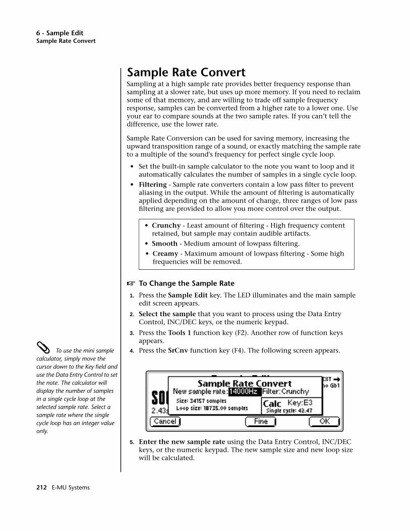
6 - Sample EditSample Rate Convert
Sample Rate ConvertSampling at a high sample rate provides better frequency response than sampling at a slower rate, but uses up more memory. If you need to reclaim some of that memory, and are willing to trade off sample frequency response, samples can be converted from a higher rate to a lower one. Use your ear to compare sounds at the two sample rates. If you can’t tell the difference, use the lower rate.
Sample Rate Conversion can be used for saving memory, increasing the upward transposition range of a sound, or exactly matching the sample rate to a multiple of the sound's frequency for perfect single cycle loop.
• Set the built-in sample calculator to the note you want to loop and it automatically calculates the number of samples in a single cycle loop.
• Filtering - Sample rate converters contain a low pass filter to prevent aliasing in the output. While the amount of filtering is automatically applied depending on the amount of change, three ranges of low pass filtering are provided to allow you more control over the output.
• Crunchy - Least amount of filtering - High frequency content retained, but sample may contain audible artifacts.
• Smooth - Medium amount of lowpass filtering.
• Creamy - Maximum amount of lowpass filtering - Some high frequencies will be removed.
v To Change the Sample Rate
1. Press the Sample Edit key. The LED illuminates and the main sample edit screen appears.
2. Select the sample that you want to process using the Data Entry Control, INC/DEC keys, or the numeric keypad.
3. Press the Tools 1 function key (F2). Another row of function keys appears.
To use the mini sample calculator, simply move the cursor down to the Key field and use the Data Entry Control to set the note. The calculator will display the number of samples in a single cycle loop at the selected sample rate. Select a sample rate where the single cycle loop has an integer value only.
4. Press the SrCnv function key (F4). The following screen appears.
5. Enter the new sample rate using the Data Entry Control, INC/DEC keys, or the numeric keypad. The new sample size and new loop size will be calculated.
212 E-MU Systems
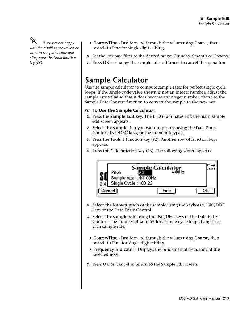
6 - Sample EditSample Calculator
OOOO If you are not happy with the resulting conversion or want to compare before and after, press the Undo function key (F6).
• Coarse/Fine - Fast forward through the values using Coarse, then switch to Fine for single digit editing.
6. Set the low pass filter to the desired range: Crunchy, Smooth or Creamy.
7. Press OK to change the sample rate or Cancel to cancel the operation.
Sample CalculatorUse the sample calculator to compute sample rates for perfect single cycle loops. If the single-cycle value shown is not an integer number, adjust the sample rate value so that it does become an integer number, then use the Sample Rate Convert function to convert the sample to the new rate.
v To Use the Sample Calculator:1. Press the Sample Edit key. The LED illuminates and the main sample
edit screen appears.
2. Select the sample that you want to process using the Data Entry Control, INC/DEC keys, or the numeric keypad.
3. Press the Tools 1 function key (F2). Another row of function keys appears.
4. Press the Calc function key (F6). The following screen appears
5. Select the known pitch of the sample using the keyboard, INC/DEC keys or the Data Entry Control.
6. Select the sample rate using the INC/DEC keys or the Data Entry Control. The number of samples for a single-cycle loop changes for each sample rate.
• Coarse/Fine - Fast forward through the values using Coarse, then switch to Fine for single digit editing.
• Frequency Indicator - Displays the fundamental frequency of the selected note.
7. Press OK or Cancel to return to the Sample Edit screen.
EOS 4.0 Software Manual 213
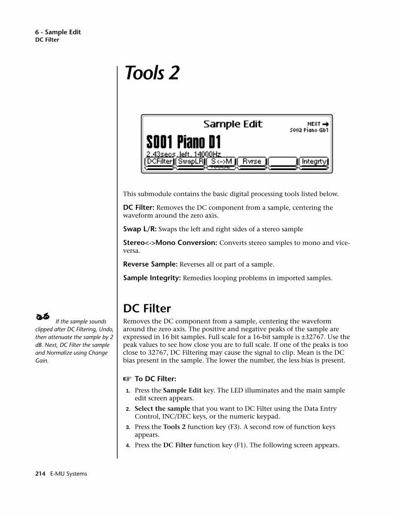
6 - Sample EditDC Filter
Tools 2
This submodule contains the basic digital processing tools listed below.
DC Filter: Removes the DC component from a sample, centering the waveform around the zero axis.
Swap L/R: Swaps the left and right sides of a stereo sample
Stereo<->Mono Conversion: Converts stereo samples to mono and vice-versa.
Reverse Sample: Reverses all or part of a sample.
Sample Integrity: Remedies looping problems in imported samples.
DC Filter____ If the sample sounds clipped after DC Filtering, Undo, then attenuate the sample by 2 dB. Next, DC Filter the sample and Normalize using Change Gain.
Removes the DC component from a sample, centering the waveform around the zero axis. The positive and negative peaks of the sample are expressed in 16 bit samples. Full scale for a 16-bit sample is ±32767. Use the peak values to see how close you are to full scale. If one of the peaks is too close to 32767, DC Filtering may cause the signal to clip. Mean is the DC bias present in the sample. The lower the number, the less bias is present.
v To DC Filter:
1. Press the Sample Edit key. The LED illuminates and the main sample edit screen appears.
2. Select the sample that you want to DC Filter using the Data Entry Control, INC/DEC keys, or the numeric keypad.
3. Press the Tools 2 function key (F3). A second row of function keys appears.
4. Press the DC Filter function key (F1). The following screen appears.
214 E-MU Systems
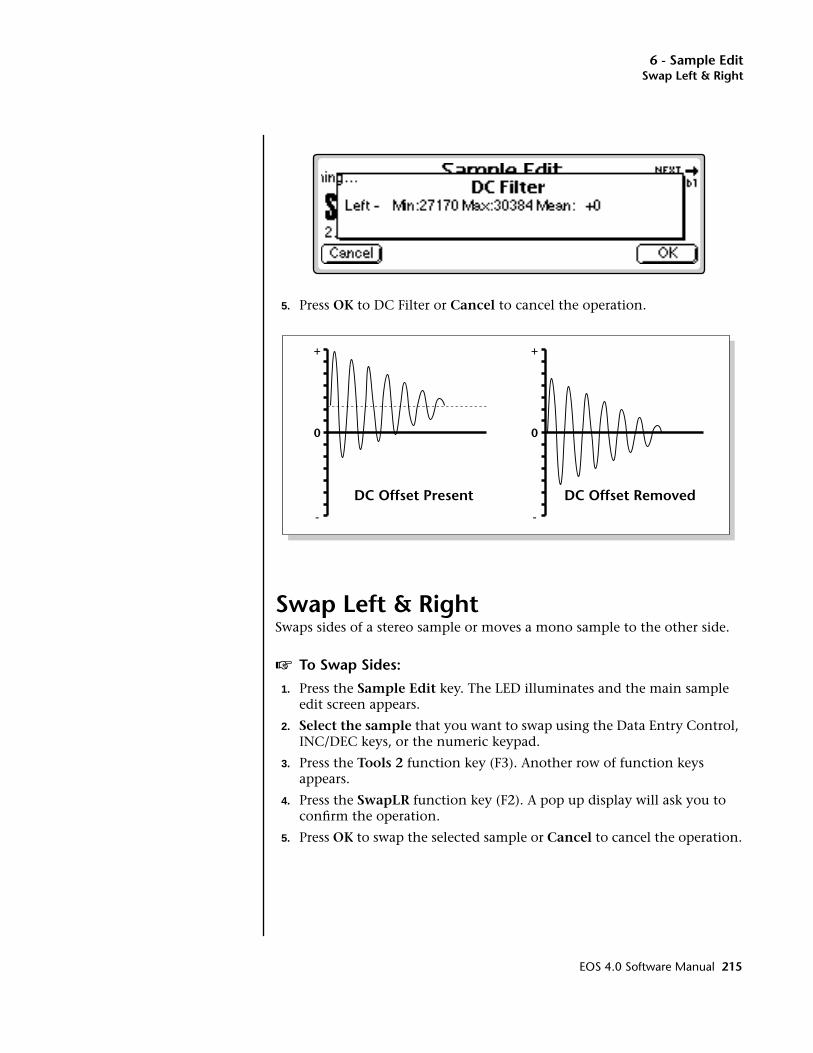
6 - Sample EditSwap Left & Right
5. Press OK to DC Filter or Cancel to cancel the operation.
Swap Left & RightSwaps sides of a stereo sample or moves a mono sample to the other side.
v To Swap Sides:
1. Press the Sample Edit key. The LED illuminates and the main sample edit screen appears.
2. Select the sample that you want to swap using the Data Entry Control, INC/DEC keys, or the numeric keypad.
3. Press the Tools 2 function key (F3). Another row of function keys appears.
4. Press the SwapLR function key (F2). A pop up display will ask you to confirm the operation.
5. Press OK to swap the selected sample or Cancel to cancel the operation.
0 0
+ +
- -
DC Offset Present DC Offset Removed
EOS 4.0 Software Manual 215
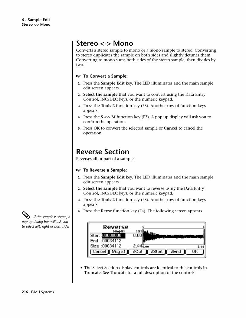
6 - Sample EditStereo <-> Mono
Stereo <-> MonoConverts a stereo sample to mono or a mono sample to stereo. Converting to stereo duplicates the sample on both sides and slightly detunes them. Converting to mono sums both sides of the stereo sample, then divides by two.
v To Convert a Sample:
1. Press the Sample Edit key. The LED illuminates and the main sample edit screen appears.
2. Select the sample that you want to convert using the Data Entry Control, INC/DEC keys, or the numeric keypad.
3. Press the Tools 2 function key (F3). Another row of function keys appears.
4. Press the S <-> M function key (F3). A pop up display will ask you to confirm the operation.
5. Press OK to convert the selected sample or Cancel to cancel the operation.
Reverse SectionReverses all or part of a sample.
v To Reverse a Sample:
1. Press the Sample Edit key. The LED illuminates and the main sample edit screen appears.
2. Select the sample that you want to reverse using the Data Entry Control, INC/DEC keys, or the numeric keypad.
3. Press the Tools 2 function key (F3). Another row of function keys appears.
4. Press the Revse function key (F4). The following screen appears. If the sample is stereo, a pop up dialog box will ask you to select left, right or both sides.
• The Select Section display controls are identical to the controls in Truncate. See Truncate for a full description of the controls.
216 E-MU Systems
6 - Sample EditSample Integrity
OOOO The Start and End points are “remembered” from module to module so that you can perform successive operations on the same section of the sample.
5. Specify the Start and End points for the portion of the sample to be reversed using the Data Entry Control, left/right cursor keys, INC/DEC keys or the numeric keypad.
• The left and right cursor buttons will change the start and end points so that they fall on positive zero-crossing points in the waveform. This will minimize clicks in the sound when processing only part of a sample.
6. Press OK to reverse the section or Cancel to cancel the operation.
Sample IntegrityImported samples may occasionally have slight looping problems (heard as ticks) due to data corruption of the sample header file. This function remedies the problem by reconstructing the sample header.
v To Fix all Samples:1. Press the Sample Edit key. The LED illuminates and the main sample
edit screen appears.
2. Press the Tools 2 function key (F3). A second row of function keys appears.
3. Press the Integrty function key (F6). You are asked, “Fix all Samples?”.
4. Press OK to fix all samples in the bank or Cancel to return to the Sample Edit screen.
EOS 4.0 Software Manual 217

6 - Sample EditGain Change
Tools 3
This submodule contains the digital processing tools listed below.
• Gain Change: Alters the level of all or part of a sample.
• Compression: The compressor dynamically changes the gain of the sample based on the amplitude envelope of the sample. This is a non-real-time implementation of a full featured dynamic range compressor.
• Parametric Equalization: This is a digital (non real-time) implemen-tation of a one band parametric EQ, with +12 dB boost or -48 dB of cut and completely variable frequency and bandwidth controls.
• FIR: Phase-linear Lowpass, Highpass, and Bandpass filters with extremely steep cutoff slopes and Q.
• Aphex Aural Exciter: This function adds brilliance and “cut” to a sample, helping it to stand out in a mix. The Aphex Exciter works by adding high order harmonics related to the source material.
Gain ChangeGain Change alters the level of all or part of a sample.
v To Change the Gain of a Sample:
1. Press the Sample Edit key. The LED illuminates and the main sample edit screen appears.
OOOO If the sample is stereo, a pop up dialog box will ask you to select left, right or both sides.
2. Select the sample that you want to Gain Change using the Data Entry Control, INC/DEC keys, or numeric keypad.
3. Press the Tools 3 function key (F4). Another row of function keys appears.
4. Press the Gain function key (F1). The following screen appears.
218 E-MU Systems

6 - Sample EditGain Change
• The Gain Change display is identical to the display in Truncate. See Truncate for a full description of the controls.
The Start and End points are “remembered” from module to module so that you can perform successive operations on the same section of the sample.
5. Specify the Start and End points for the selected portion of the sample using the Data Entry Control, left/right cursor keys, INC/DEC keys or the numeric keypad.
6. Press OK to continue on to the next page of options or Cancel to cancel the operation.
Several more parameters are shown.
• Amount: This is the amount of attenuation or gain applied to the selected section and is also variable from -96 dB to +96 dB.
• Normalize: This is a display showing the amount of gain change needed to achieve normalization or 0 dB headroom. Adding more positive gain change than the amount shown in the normalize dis-play will cause the signal to clip.
• Fade Size: Set the length of the crossfade between the unaffected sample and the full amount of gain change.
If you are not happy with the resulting gain change or want to compare before and after, press the Undo function key (F6).
• Fade Type: Selects the type of fade curve: Linear, Exp. 1, Exp. 2. Exp. 3. The graphs of these curves are shown on the following page.
EOS 4.0 Software Manual 219
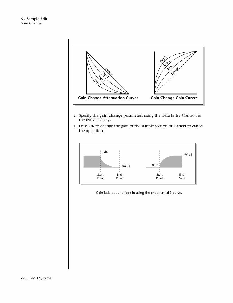
6 - Sample EditGain Change
7. Specify the gain change parameters using the Data Entry Control, or the INC/DEC keys.
8. Press OK to change the gain of the sample section or Cancel to cancel the operation.
Gain fade-out and fade-in using the exponential 3 curve.
Exp 2Exp 3
Exp 1
Linear
Exp 2Ex
p 3
Exp 1
Linea
r
Gain Change Attenuation Curves Gain Change Gain Curves
0 dB
-96 dB
EndPoint
StartPoint
StartPoint
0 dB
-96 dB
EndPoint
220 E-MU Systems
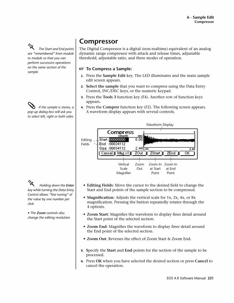
6 - Sample EditCompressor
CompressorOOOO The Start and End points are “remembered” from module to module so that you can perform successive operations on the same section of the sample.
The Digital Compressor is a digital (non-realtime) equivalent of an analog dynamic range compressor with attack and release times, adjustable threshold, adjustable ratio, and three modes of operation.
v To Compress a Sample:
1. Press the Sample Edit key. The LED illuminates and the main sample edit screen appears.
2. Select the sample that you want to compress using the Data Entry Control, INC/DEC keys, or the numeric keypad.
3. Press the Tools 3 function key (F4). Another row of function keys appears.
If the sample is stereo, a pop up dialog box will ask you to select left, right or both sides.
4. Press the Comprsr function key (F2). The following screen appears. A waveform display appears with several controls.
OOOO Holding down the Enter key while turning the Data Entry Control allows “fine tuning” of the value by one number per click.
• The Zoom controls also change the editing resolution.
• Editing Fields: Move the cursor to the desired field to change the Start and End points of the sample section to be compressed.
• Magnification: Adjusts the vertical scale for 1x, 2x, 4x, or 8x magnification. Pressing the button repeatedly rotates through the 4 options.
• Zoom Start: Magnifies the waveform to display finer detail around the Start point of the selected section.
• Zoom End: Magnifies the waveform to display finer detail around the End point of the selected section.
• Zoom Out: Reverses the effect of Zoom Start & Zoom End.
5. Specify the Start and End points for the section of the sample to be processed.
6. Press OK when you have selected the desired section or press Cancel to cancel the operation.
Waveform Display
EditingFields
VerticalScale
Magnifier
ZoomOut
Zoom Inat StartPoint
Zoom Inat EndPoint
EOS 4.0 Software Manual 221
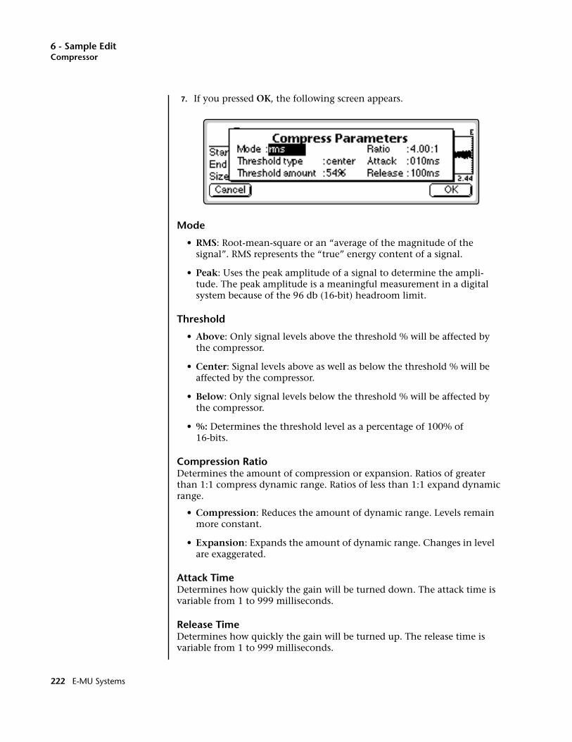
6 - Sample EditCompressor
7. If you pressed OK, the following screen appears.
Mode
• RMS: Root-mean-square or an “average of the magnitude of the signal”. RMS represents the “true” energy content of a signal.
• Peak: Uses the peak amplitude of a signal to determine the ampli-tude. The peak amplitude is a meaningful measurement in a digital system because of the 96 db (16-bit) headroom limit.
Threshold
• Above: Only signal levels above the threshold % will be affected by the compressor.
• Center: Signal levels above as well as below the threshold % will be affected by the compressor.
• Below: Only signal levels below the threshold % will be affected by the compressor.
• %: Determines the threshold level as a percentage of 100% of 16-bits.
Compression RatioDetermines the amount of compression or expansion. Ratios of greater than 1:1 compress dynamic range. Ratios of less than 1:1 expand dynamic range.
• Compression: Reduces the amount of dynamic range. Levels remain more constant.
• Expansion: Expands the amount of dynamic range. Changes in level are exaggerated.
Attack TimeDetermines how quickly the gain will be turned down. The attack time is variable from 1 to 999 milliseconds.
Release TimeDetermines how quickly the gain will be turned up. The release time is variable from 1 to 999 milliseconds.
222 E-MU Systems

6 - Sample EditCompressor
8. Press OK when you have set the desired options or press Cancel to cancel the operation.
0%
1:1
2:1
10:150%
100%
Above
Threshold
0%
1:1
2:110:1
50%
100%
Center
Threshold
0%1:1
2:1
10:150%Threshold
100%
Below
Compressor Threshold
Only signal levels ABOVE the Threshold percentage will be affected by the compressor.
Signal levels ABOVE as well as BELOW the Threshold percentage will be affected by the compressor.
Only signal levels BELOW the Threshold percentage will be affected by the compressor.
EOS 4.0 Software Manual 223
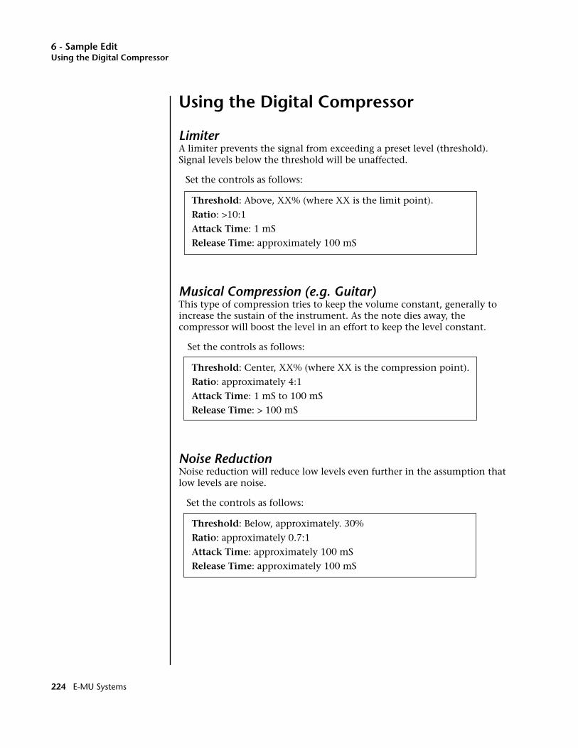
6 - Sample EditUsing the Digital Compressor
Using the Digital Compressor
LimiterA limiter prevents the signal from exceeding a preset level (threshold). Signal levels below the threshold will be unaffected.
Set the controls as follows:
Threshold: Above, XX% (where XX is the limit point).
Ratio: >10:1
Attack Time: 1 mS
Release Time: approximately 100 mS
Musical Compression (e.g. Guitar)This type of compression tries to keep the volume constant, generally to increase the sustain of the instrument. As the note dies away, the compressor will boost the level in an effort to keep the level constant.
Set the controls as follows:
Threshold: Center, XX% (where XX is the compression point).
Ratio: approximately 4:1
Attack Time: 1 mS to 100 mS
Release Time: > 100 mS
Noise ReductionNoise reduction will reduce low levels even further in the assumption that low levels are noise.
Set the controls as follows:
Threshold: Below, approximately. 30%
Ratio: approximately 0.7:1
Attack Time: approximately 100 mS
Release Time: approximately 100 mS
224 E-MU Systems

6 - Sample EditParametric Equalizer
Parametric EqualizerOOOO The Start and End points are “remembered” from module to module so that you can perform successive operations on the same section of the sample.
Parametric EQ allows you adjust the individual parameters of the filter. Boost/Cut controls “how much” of the signal will be boosted or cut. Center Frequency sets the center frequency to be boosted or cut, and the Bandwidth control sets the width of the band to be boosted or cut. The three parameters are diagrammed on the following page.
The parametric equalizer is a digital (non real-time) equivalent of an analog equalizer with +12 dB of boost and a whopping -48 dB of cut. Center frequency and bandwidth controls are accurate, precise and have an excep-tionally wide range.
OOOO The left and right cursor buttons will change the start and end points so that they fall on positive zero-crossing points in the waveform. This will minimize clicks in the sound when processing only part of a sample.
v To Filter a Sample:
1. Press the Sample Edit key. The LED illuminates and the main sample edit screen appears.
2. Select the sample that you want to equalize using the Data Entry Control, INC/DEC keys, or the numeric keypad.
3. Press the Tools 3 function key (F4). Another row of function keys appears.
4. Press the ParEQ function key (F3). The following screen appears.
OOOO If the sample is stereo, a pop up dialog box will ask you to select left, right or both sides.
• The Select Section display controls are identical to the controls in Truncate. See Truncate for a full description of the controls.
5. Specify the Start and End points for the portion of the sample to be EQ'ed using the Data Entry Control, left/right cursor keys, INC/DEC keys or the numeric keypad.
OOOO Holding down the Enter key while turning the Data Entry Control allows “fine tuning” of the value by one number per click.
6. Press OK to continue on to the next page of options or Cancel to cancel the operation.
EOS 4.0 Software Manual 225
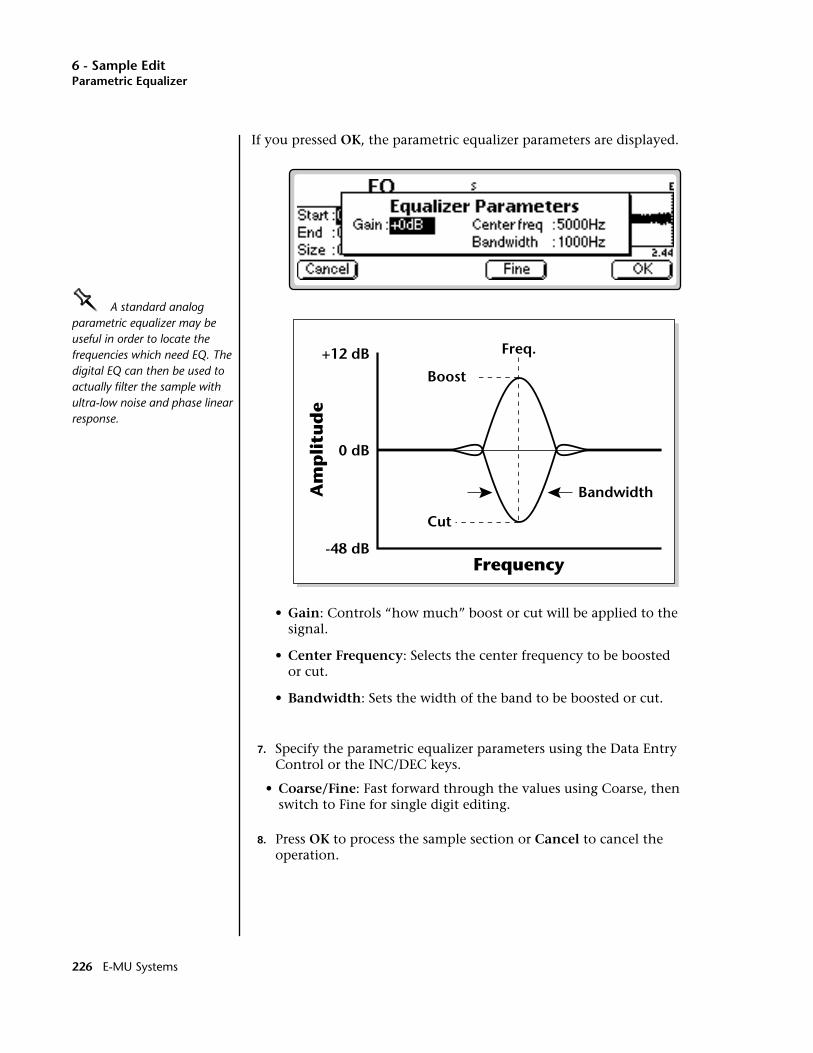
6 - Sample EditParametric Equalizer
If you pressed OK, the parametric equalizer parameters are displayed.
OOOO A standard analog parametric equalizer may be useful in order to locate the frequencies which need EQ. The digital EQ can then be used to actually filter the sample with ultra-low noise and phase linear response.
• Gain: Controls “how much” boost or cut will be applied to the signal.
• Center Frequency: Selects the center frequency to be boosted or cut.
• Bandwidth: Sets the width of the band to be boosted or cut.
7. Specify the parametric equalizer parameters using the Data Entry Control or the INC/DEC keys.
• Coarse/Fine: Fast forward through the values using Coarse, then switch to Fine for single digit editing.
8. Press OK to process the sample section or Cancel to cancel the operation.
Boost
Cut
Freq.
0 dB
+12 dB
-48 dB
Bandwidth
Frequency
Am
pli
tud
e
226 E-MU Systems

6 - Sample EditFIR (Phase Linear Filter)
FIR (Phase Linear Filter)The phase linear filter was originally developed on the EIII to separate the attack and sustain portions of piano samples. Ordinary filters cause serious phase distortion at the cutoff point. This FIR filter has much less phase distortion than a typical filter and so is better suited for sample splicing. The phase linear filter acts on the ENTIRE sample, unlike the parametric filter which can filter any portion of the sample. This ensures strict phase-linearity. There are five types of phase linear filters available: Lowpass, Highpass, Bandpass, Allpass and Notch.
The Points parameter determines the Quality or Q of the filter. The larger the Point value, the more the filter behaves like an ideal filter and the steeper the filter slope. The Points parameter is variable from 5 to 99.
The Frequency parameter determines the cutoff frequency of the filter and is calibrated in Hertz. When Bandpass or Notch filters are selected, a second frequency field appears to allow you to specify the frequencies on either side of the passband or notch.
The Allpass filter is a special purpose filter that is used to add delay to a sample before it is recombined with a filtered sample. Recombining allows you to perform band-splitting or frequency boosting instead of frequency attenuation.
v To Filter a Sample:1. Press the Sample Edit key. The LED illuminates and the main sample
edit screen appears.
2. Select the sample that you want to equalize using the Data Entry Control, INC/DEC keys, or the numeric keypad.
3. Press the Tools 3 function key (F4). Another row of function keys appears.
4. Press the FIR function key (F4). The following screen appears.
5. Select the filter Type: Lowpass, Highpass, bandpass, Notch or Allpass.OOOO Holding down the Enter key while turning the Data Entry Control allows “fine tuning” of the value by one number per click.
6. Set the filter slope by adjusting the Points parameter. The higher the number, the steeper the filter slope.
7. Set the Frequency parameter to the desired frequency. If you chose the Bandpass or Notch filters, the Frequency 2 field will appear, allowing you to set the lower frequency in the range.
8. Press OK to filter the sample or Cancel to cancel the operation.
EOS 4.0 Software Manual 227

6 - Sample EditFIR (Phase Linear Filter)
• Alternate Filter Responses
Low Shelving Boost - Add Lowpass with original signal.
High Shelving Boost - Add Highpass with original signal.
Band Boost - Add Bandpass with original signal.
The Allpass filter can be used to achieve complex formants, notches or frequency boosts by copying, filtering and adding the original sample to the filtered version. When adding filtered signals with the FIR, each signal must be processed through the same number of points to preserve phase-linearity. The diagram below shows the incorrect and correct ways to add signals together.
The signal is passed through the Phase-linear filter and recombined with the original signal to create a low frequency boost. Because of the filtering, the two signals are now out of phase. The Allpass filter, set to the same point size, is used to correct the problem.
+10dB
+20dB
0dB
-10dB
-20dB
-30dB
-40dB
-50dB
-60dB
-70dB
-80dB
0 0.1 0.2 0.3 0.4 0.5 0.6 0.7 0.8 0.9 1
Frequency
Att
enu
atio
n 5 points
99 points
Filter Size and Slope
(rad x pi)
This chart shows the relationship between the filter Points and Slope.
Low Pass50 Pts.
All Pass50 Pts.
SumSample
Signals AddIn Phase
Copy ofSample
Low Pass50 Pts.
Sum
Sample
Signals AddOut of Phase
Copy ofSample
Creating a Low Frequency Boost EQ
228 E-MU Systems
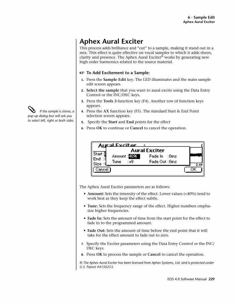
6 - Sample EditAphex Aural Exciter
Aphex Aural ExciterThis process adds brilliance and “cut” to a sample, making it stand out in a mix. This effect is quite effective on vocal samples to which it adds sheen, clarity and presence. The Aphex Aural Exciter® works by generating new high order harmonics related to the source material.
v To Add Excitement to a Sample:
1. Press the Sample Edit key. The LED illuminates and the main sample edit screen appears.
2. Select the sample that you want to aural excite using the Data Entry Control or the INC/DEC keys.
3. Press the Tools 3 function key (F4). Another row of function keys appears.
If the sample is stereo, a pop up dialog box will ask you to select left, right or both sides.
4. Press the AX function key (F5). The standard Start & End Point selection screen appears.
5. Specify the Start and End points for the effect
6. Press OK to continue or Cancel to cancel the operation.
The Aphex Aural Exciter parameters are as follows:
• Amount: Sets the intensity of the effect. Lower values (<40%) tend to work best as they keep the effect subtle.
• Tune: Sets the frequency range of the effect. Higher numbers empha-size higher frequencies.
• Fade In: Sets the amount of time from the start point for the effect to fade in to the programmed amount.
• Fade Out: Sets the amount of time before the end point that it will take for the effect amount to fade out to zero.
7. Specify the Exciter parameters using the Data Entry Control or the INC/DEC keys.
8. Press OK to process the sample or Cancel to cancel the operation.
® The Aphex Aural Exciter has been licensed from Aphex Systems, Ltd. and is protected under U.S. Patent #4150253.
EOS 4.0 Software Manual 229

6 - Sample EditTools 4
Tools 4
This submodule contains the advanced digital processing tools listed below.
Transform Multiplication: This function merges two sounds together in a unique way which can create many strange and beautiful sonic textures. Frequencies common to the original sounds are accentuated while uncommon frequencies are discarded.
Doppler: This unique function allows you to dramatically move a sound from front to back and side to side in a 3-D space. Several pre-computed paths are available.
Time Compression: This function changes the length of a sample without changing the pitch. This can be very useful for fitting samples to the beat of a song or fitting dialog into a spot. Samples can be compressed or expanded in length from 50% to 200%.
Pitch Change: This function changes the pitch of a sample without changing the time relationships between events. The maximum amount of pitch change is ±1200 cents (± one octave).
Bit Converter: This function allows you to decrease the bit resolution of your samples.
Beat Munger: This amazing feature lets you change the tempo, time signature and add or subtract swing from recorded music. (Available only on Ultra Emulators.)
230 E-MU Systems

6 - Sample EditTransform Multiplication
Transform Multiplication____ Caution: Transform Multiplication can take quite a bit of time with longer samples. Begin your experiments with short samples or even sample attacks as these will give good initial results.
This unique function merges two sounds together so that frequencies common to both sounds are accentuated while uncommon frequencies are discarded (also called Convolution). Because of this characteristic, Transform Multiplication tends to work best with sounds that are harmonically rich. Transform Multiplication is a powerful synthesis technique which can produce strange and beautiful timbres. Try it!
Using this function is easy, just pick two sounds and go. The length of the resulting sample will be equal to that of the current sample.
v To Transform Multiply Two Samples:
1. Press the Sample Edit key. The LED illuminates and the main sample edit screen appears.
2. Select the first sample that you want to multiply using the Data Entry Control, INC/DEC keys, or the numeric keypad.
3. Press the Tools 4 function key (F5). Another row of function keys appears.
OOOO Ideas for using Transform Multiplication:• Try using the same sound for both samples.
• Splicing silence to the beginnings or ends of short samples can change the spectral characteristics of the result.
• Using speech as one of the sources, it is possible to “speak from within” violins, bassoons, cymbals, etc.
4. Press the XMult function key (F1). The following screen appears.
5. Select the second sample to be multiplied using the Data Entry Control or the INC/DEC keys. The second line of the window will show the sample length and rate of the second sample.
6. Press OK to begin processing or Cancel to cancel the operation.
EOS 4.0 Software Manual 231
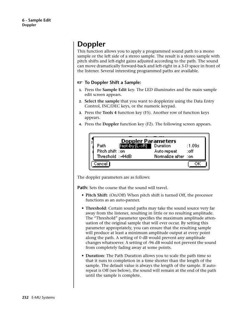
6 - Sample EditDoppler
DopplerThis function allows you to apply a programmed sound path to a mono sample or the left side of a stereo sample. The result is a stereo sample with pitch shifts and left-right gains adjusted according to the path. The sound can move dramatically forward-back and left-right in a 3-D space in front of the listener. Several interesting programmed paths are available.
v To Doppler Shift a Sample:
1. Press the Sample Edit key. The LED illuminates and the main sample edit screen appears.
2. Select the sample that you want to dopplerize using the Data Entry Control, INC/DEC keys, or the numeric keypad.
3. Press the Tools 4 function key (F5). Another row of function keys appears.
4. Press the Doppler function key (F2). The following screen appears.
The doppler parameters are as follows:
Path: Sets the course that the sound will travel.
• Pitch Shift: (On/Off) When pitch shift is turned Off, the processor functions as an auto-panner.
• Threshold: Certain sound paths may take the sound source very far away from the listener, resulting in little or no resulting amplitude. The “Threshold” parameter specifies the maximum amplitude atten-uation of the original sample that will ever occur. By setting this parameter appropriately, you can ensure that the resulting sample will produce at least a minimum amplitude output at every point along the path. A setting of 0 dB would prevent any amplitude changes whatsoever. A setting of -96 dB would not prevent the sound from completely fading away at some points.
• Duration: The Path Duration allows you to scale the path time so that it runs to completion in a time shorter than the length of the sample. The default value is always the length of the sample. If auto-repeat is Off (see below), the sound will remain at the end of the path until the sample is complete.
232 E-MU Systems
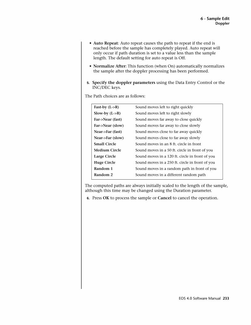
6 - Sample EditDoppler
• Auto Repeat: Auto repeat causes the path to repeat if the end is reached before the sample has completely played. Auto repeat will only occur if path duration is set to a value less than the sample length. The default setting for auto repeat is Off.
• Normalize After: This function (when On) automatically normalizes the sample after the doppler processing has been performed.
5. Specify the doppler parameters using the Data Entry Control or the INC/DEC keys.
The Path choices are as follows:
The computed paths are always initially scaled to the length of the sample, although this time may be changed using the Duration parameter.
6. Press OK to process the sample or Cancel to cancel the operation.
Fast-by (L->R) Sound moves left to right quickly
Slow-by (L->R) Sound moves left to right slowly
Far->Near (fast) Sound moves far away to close quickly
Far->Near (slow) Sound moves far away to close slowly
Near->Far (fast) Sound moves close to far away quickly
Near->Far (slow) Sound moves close to far away slowly
Small Circle Sound moves in an 8 ft. circle in front
Medium Circle Sound moves in a 50 ft. circle in front of you
Large Circle Sound moves in a 120 ft. circle in front of you
Huge Circle Sound moves in a 250 ft. circle in front of you
Random 1 Sound moves in a random path in front of you
Random 2 Sound moves in a different random path
EOS 4.0 Software Manual 233
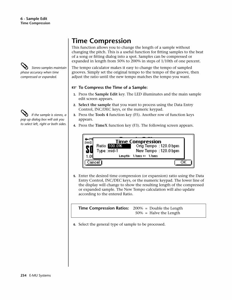
6 - Sample EditTime Compression
Time CompressionThis function allows you to change the length of a sample without changing the pitch. This is a useful function for fitting samples to the beat of a song or fitting dialog into a spot. Samples can be compressed or expanded in length from 50% to 200% in steps of 1/10th of one percent.
Stereo samples maintain phase accuracy when time compressed or expanded.
The tempo calculator makes it easy to change the tempo of sampled grooves. Simply set the original tempo to the tempo of the groove, then adjust the ratio until the new tempo matches the tempo you want.
v To Compress the Time of a Sample:
1. Press the Sample Edit key. The LED illuminates and the main sample edit screen appears.
2. Select the sample that you want to process using the Data Entry Control, INC/DEC keys, or the numeric keypad.
If the sample is stereo, a pop up dialog box will ask you to select left, right or both sides.
3. Press the Tools 4 function key (F5). Another row of function keys appears.
4. Press the TimeX function key (F3). The following screen appears.
5. Enter the desired time compression (or expansion) ratio using the Data Entry Control, INC/DEC keys, or the numeric keypad. The lower line of the display will change to show the resulting length of the compressed or expanded sample. The New Tempo calculation will also update according to the entered Ratio.
Time Compression Ratios: 200% = Double the Length 50% = Halve the Length
6. Select the general type of sample to be processed.
234 E-MU Systems
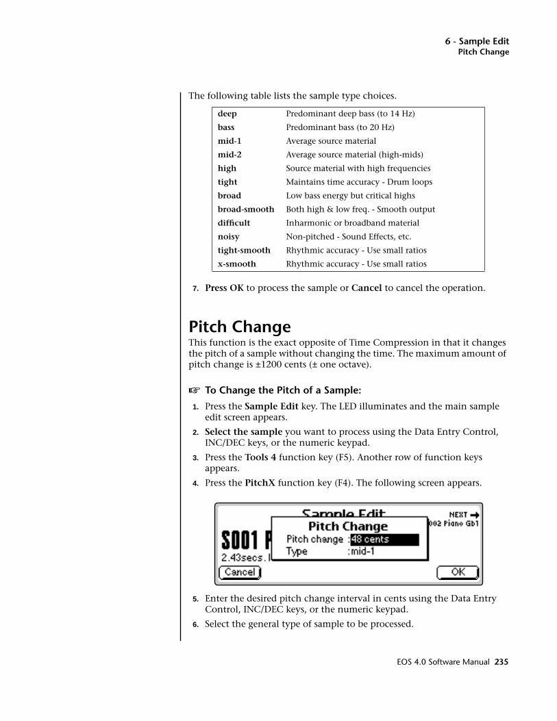
6 - Sample EditPitch Change
The following table lists the sample type choices.
7. Press OK to process the sample or Cancel to cancel the operation.
Pitch ChangeThis function is the exact opposite of Time Compression in that it changes the pitch of a sample without changing the time. The maximum amount of pitch change is ±1200 cents (± one octave).
v To Change the Pitch of a Sample:
1. Press the Sample Edit key. The LED illuminates and the main sample edit screen appears.
2. Select the sample you want to process using the Data Entry Control, INC/DEC keys, or the numeric keypad.
3. Press the Tools 4 function key (F5). Another row of function keys appears.
4. Press the PitchX function key (F4). The following screen appears.
5. Enter the desired pitch change interval in cents using the Data Entry Control, INC/DEC keys, or the numeric keypad.
6. Select the general type of sample to be processed.
deep Predominant deep bass (to 14 Hz)
bass Predominant bass (to 20 Hz)
mid-1 Average source material
mid-2 Average source material (high-mids)
high Source material with high frequencies
tight Maintains time accuracy - Drum loops
broad Low bass energy but critical highs
broad-smooth Both high & low freq. - Smooth output
difficult Inharmonic or broadband material
noisy Non-pitched - Sound Effects, etc.
tight-smooth Rhythmic accuracy - Use small ratios
x-smooth Rhythmic accuracy - Use small ratios
EOS 4.0 Software Manual 235
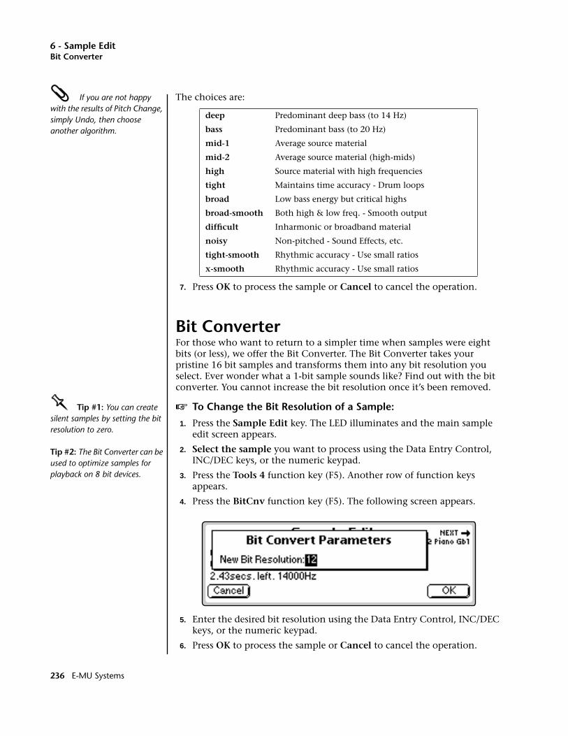
6 - Sample EditBit Converter
If you are not happy with the results of Pitch Change, simply Undo, then choose another algorithm.
The choices are:
7. Press OK to process the sample or Cancel to cancel the operation.
Bit ConverterFor those who want to return to a simpler time when samples were eight bits (or less), we offer the Bit Converter. The Bit Converter takes your pristine 16 bit samples and transforms them into any bit resolution you select. Ever wonder what a 1-bit sample sounds like? Find out with the bit converter. You cannot increase the bit resolution once it’s been removed.
OOOO Tip #1: You can create silent samples by setting the bit resolution to zero.
Tip #2: The Bit Converter can be used to optimize samples for playback on 8 bit devices.
v To Change the Bit Resolution of a Sample:
1. Press the Sample Edit key. The LED illuminates and the main sample edit screen appears.
2. Select the sample you want to process using the Data Entry Control, INC/DEC keys, or the numeric keypad.
3. Press the Tools 4 function key (F5). Another row of function keys appears.
4. Press the BitCnv function key (F5). The following screen appears.
5. Enter the desired bit resolution using the Data Entry Control, INC/DEC keys, or the numeric keypad.
6. Press OK to process the sample or Cancel to cancel the operation.
deep Predominant deep bass (to 14 Hz)
bass Predominant bass (to 20 Hz)
mid-1 Average source material
mid-2 Average source material (high-mids)
high Source material with high frequencies
tight Maintains time accuracy - Drum loops
broad Low bass energy but critical highs
broad-smooth Both high & low freq. - Smooth output
difficult Inharmonic or broadband material
noisy Non-pitched - Sound Effects, etc.
tight-smooth Rhythmic accuracy - Use small ratios
x-smooth Rhythmic accuracy - Use small ratios
236 E-MU Systems
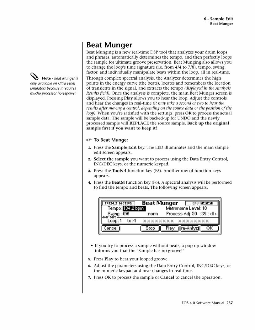
6 - Sample EditBeat Munger
Beat MungerBeat Munging is a new real-time DSP tool that analyzes your drum loops and phrases, automatically determines the tempo, and then perfectly loops the sample for ultimate groove preservation. Beat Munging also allows you to change the loop’s time signature (i.e. from 4/4 to 7/8), tempo, swing factor, and individually manipulate beats within the loop, all in real-time.
Note - Beat Munger is only available on Ultra series Emulators because it requires mucho processor horsepower.
Through complex spectral analysis, the Analyzer determines the high points in the energy curve (the beats), locates and remembers the location of transients in the signal, and extracts the tempo (displayed in the Analysis Results field). Once the analysis is complete, the main Beat Munger screen is displayed. Pressing Play allows you to hear the loop. Adjust the controls and hear the changes in real-time (it may take a second or two to hear the results after moving a control, depending on the source data or the position of the loop). When you’re satisfied with the settings, press OK to process the actual sample data. The sample will be backed-up for UNDO and the newly processed sample will REPLACE the source sample. Back up the original sample first if you want to keep it!
v To Beat Munge:
1. Press the Sample Edit key. The LED illuminates and the main sample edit screen appears.
2. Select the sample you want to process using the Data Entry Control, INC/DEC keys, or the numeric keypad.
3. Press the Tools 4 function key (F5). Another row of function keys appears.
4. Press the BeatM function key (F6). A spectral analysis will be performed to find the tempo and beats. The following screen appears.
• If you try to process a sample without beats, a pop-up window informs you that the “Sample has no groove!”
5. Press Play to hear your looped groove.
6. Adjust the parameters using the Data Entry Control, INC/DEC keys, or the numeric keypad and hear changes in real-time.
7. Press OK to process the sample or Cancel to cancel the operation.
EOS 4.0 Software Manual 237

6 - Sample EditBeat Munger
Beat Munger Controls• Analysis Results: This field displays the analyzed tempo and number
of beats in the sample. The sample may contain any number of beats and this number will also be displayed in the Loop Controls field.
• Tempo Adjust: Adjusts the Tempo of the loop (you knew that) with-out altering the pitch. The Tempo field defaults to the tempo determined from the analysis.
• Swing Adjust & Control: Swing can be modified in both a positive and negative (anti-swing) direction. Negative swing can actually remove swing from a groove.
With Swing set to “Norm” and “0%”, each quarter note is weighted so that the first eighth note takes up 50% of the quarter note and the second eighth note takes up the other 50%. When the swing factor is changed to a positive amount, the first eighth note takes up more of the time and the second eighth note gets the rest. Negative swing lengthens the time spent on the second eighth note
There are four different swing controls.Fast . . . . . . . . . . . Swings within an eighth noteNorm . . . . . . . . . Swings within an quarter note Slow . . . . . . . . . . Swings within a half note
• Loop Boundary Control: These controls allow you to redefine the start and end points of the loop. For example, you could remove the first beat of a loop or the last bar of a four bar loop. The default setting of this field is determined by the length of the loop.
• Downbeat Selection: Sometimes Beat Munger makes a mistake when choosing the proper downbeat and may choose an upbeat instead. This control allows you to correct the mistake. Depending on the source material, several choices may be provided. Use this feature in conjunction with the metronome. You can also use this control to deliberately place the accent on other beats.
CPU MeterAnalysis Results Swing Control
TempoAdjust
ProcessSample
8th NoteGrid
Grunge
Comb
DownbeatSelectionSwing
Adjust
Re-AnalyzeLoop
AuditionLoop
StopAudition
LoopBoundaryControl
238 E-MU Systems
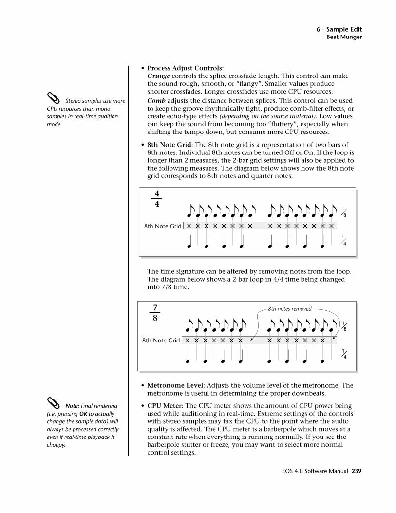
6 - Sample EditBeat Munger
• Process Adjust Controls:Grunge controls the splice crossfade length. This control can make the sound rough, smooth, or “flangy”. Smaller values produce shorter crossfades. Longer crossfades use more CPU resources.
Stereo samples use more CPU resources than mono samples in real-time audition mode.
Comb adjusts the distance between splices. This control can be used to keep the groove rhythmically tight, produce comb-filter effects, or create echo-type effects (depending on the source material). Low values can keep the sound from becoming too “fluttery”, especially when shifting the tempo down, but consume more CPU resources.
• 8th Note Grid: The 8th note grid is a representation of two bars of 8th notes. Individual 8th notes can be turned Off or On. If the loop is longer than 2 measures, the 2-bar grid settings will also be applied to the following measures. The diagram below shows how the 8th note grid corresponds to 8th notes and quarter notes.
The time signature can be altered by removing notes from the loop. The diagram below shows a 2-bar loop in 4/4 time being changed into 7/8 time.
• Metronome Level: Adjusts the volume level of the metronome. The metronome is useful in determining the proper downbeats.
Note: Final rendering (i.e. pressing OK to actually change the sample data) will always be processed correctly even if real-time playback is choppy.
• CPU Meter: The CPU meter shows the amount of CPU power being used while auditioning in real-time. Extreme settings of the controls with stereo samples may tax the CPU to the point where the audio quality is affected. The CPU meter is a barberpole which moves at a constant rate when everything is running normally. If you see the barberpole stutter or freeze, you may want to select more normal control settings.
18
14
8th Note Grid
44
18
14
8th Note Grid
78
8th notes removed
EOS 4.0 Software Manual 239
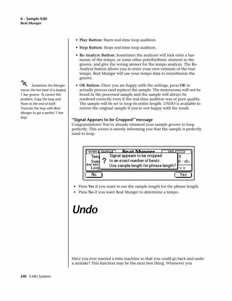
6 - Sample EditBeat Munger
• Play Button: Starts real-time loop audition.
• Stop Button: Stops real-time loop audition.
• Re-Analyze Button: Sometimes the analyzer will lock onto a har-monic of the tempo, or some other polyrhythmic element in the groove, and give the wrong answer for the tempo analysis. The Re-Analyze button allows you to enter your own estimate of the true tempo. Beat Munger will use your tempo data to resynthesize the groove.
OOOO Sometimes the Munger misses the last beat of a looped, 1 bar groove. To correct this problem, Copy the loop and Paste to the end of itself. Truncate the loop with Beat Munger to get a perfect 1 bar loop.
• OK Button: Once you are happy with the settings, press OK to actually process (and replace) the sample. The metronome will not be heard in the processed sample and the sample will always be rendered correctly even if the real-time audition was of poor quality. The sample will be set to loop its entire length. UNDO is available to restore the original sample if you’re not happy with the result.
“Signal Appears to be Cropped” messageCongratulations! You’ve already trimmed your sample groove to loop perfectly. This screen is merely informing you that the sample is perfectly sized to loop.
• Press Yes if you want to use the sample length for the phrase length.
• Press No if you want Beat Munger to determine a tempo.
Undo
Have you ever wanted a time machine so that you could go back and undo a mistake? This function may be the next best thing. Whenever you
240 E-MU Systems
6 - Sample EditUndo
perform a sample edit function, the original version of the sample will be backed up if “Undo/Redo” is enabled (Master, Miscellaneous). The original sample is placed on the clipboard and can be instantly restored by pressing Undo.
v To Restore a Sample to its Original State
1. Press the Sample Edit key. The LED illuminates and the main sample edit screen appears.
2. Press the UNDO! function key (F6). The original sample will be restored and the processed sample will be stored in the clipboard.
v To Compare a Processed Sample with the Original Sample:
1. Press the Sample Edit key. The LED illuminates and the main sample edit screen appears.
2. Press the UNDO! function key (F6). The original sample will be restored and the processed sample will be store in the clipboard.
3. Press the REDO! function key (F6) again. The processed sample will be restored and the original sample will be stored in the clipboard. You can continue switching back and forth until you decide which sample you want to keep.
EOS 4.0 Software Manual 241

6 - Sample Edit
242 E-MU Systems

7 - Preset Manage
7Preset Manage
EOS 4.0 Software Manual 243

7 - Preset Manage
244 E-MU Systems
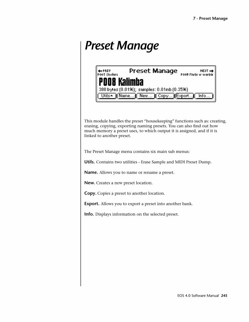
7 - Preset Manage
Preset Manage
This module handles the preset “housekeeping” functions such as: creating, erasing, copying, exporting naming presets. You can also find out how much memory a preset uses, to which output it is assigned, and if it is linked to another preset.
The Preset Manage menu contains six main sub menus:
Utils. Contains two utilities - Erase Sample and MIDI Preset Dump.
Name. Allows you to name or rename a preset.
New. Creates a new preset location.
Copy. Copies a preset to another location.
Export. Allows you to export a preset into another bank.
Info. Displays information on the selected preset.
EOS 4.0 Software Manual 245
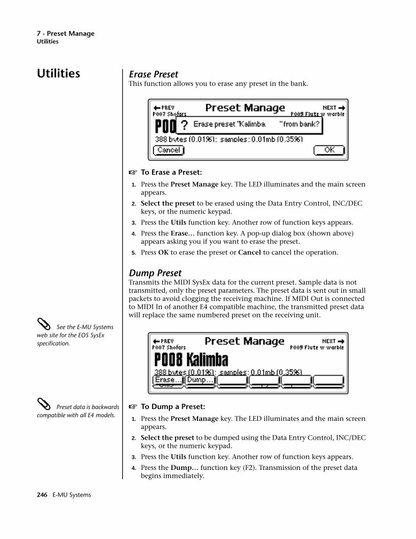
7 - Preset ManageUtilities
Utilities Erase PresetThis function allows you to erase any preset in the bank.
v To Erase a Preset:
1. Press the Preset Manage key. The LED illuminates and the main screen appears.
2. Select the preset to be erased using the Data Entry Control, INC/DEC keys, or the numeric keypad.
3. Press the Utils function key. Another row of function keys appears.
4. Press the Erase… function key. A pop-up dialog box (shown above) appears asking you if you want to erase the preset.
5. Press OK to erase the preset or Cancel to cancel the operation.
Dump PresetTransmits the MIDI SysEx data for the current preset. Sample data is not transmitted, only the preset parameters. The preset data is sent out in small packets to avoid clogging the receiving machine. If MIDI Out is connected to MIDI In of another E4 compatible machine, the transmitted preset data will replace the same numbered preset on the receiving unit.
See the E-MU Systems web site for the EOS SysEx specification.
Preset data is backwards compatible with all E4 models.
v To Dump a Preset:
1. Press the Preset Manage key. The LED illuminates and the main screen appears.
2. Select the preset to be dumped using the Data Entry Control, INC/DEC keys, or the numeric keypad.
3. Press the Utils function key. Another row of function keys appears.
4. Press the Dump… function key (F2). Transmission of the preset data begins immediately.
246 E-MU Systems
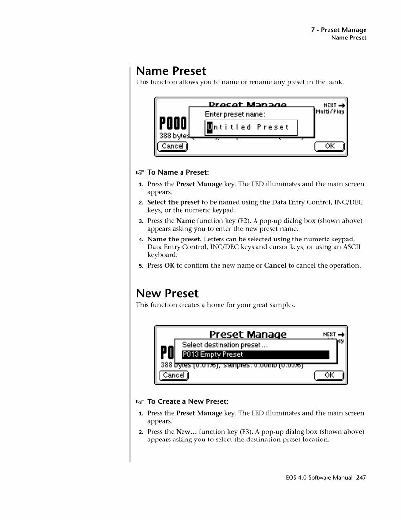
7 - Preset ManageName Preset
Name PresetThis function allows you to name or rename any preset in the bank.
v To Name a Preset:
1. Press the Preset Manage key. The LED illuminates and the main screen appears.
2. Select the preset to be named using the Data Entry Control, INC/DEC keys, or the numeric keypad.
3. Press the Name function key (F2). A pop-up dialog box (shown above) appears asking you to enter the new preset name.
4. Name the preset. Letters can be selected using the numeric keypad, Data Entry Control, INC/DEC keys and cursor keys, or using an ASCII keyboard.
5. Press OK to confirm the new name or Cancel to cancel the operation.
New PresetThis function creates a home for your great samples.
v To Create a New Preset:
1. Press the Preset Manage key. The LED illuminates and the main screen appears.
2. Press the New… function key (F3). A pop-up dialog box (shown above) appears asking you to select the destination preset location.
EOS 4.0 Software Manual 247
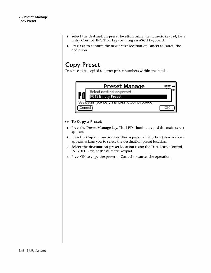
7 - Preset ManageCopy Preset
3. Select the destination preset location using the numeric keypad, Data Entry Control, INC/DEC keys or using an ASCII keyboard.
4. Press OK to confirm the new preset location or Cancel to cancel the operation.
Copy PresetPresets can be copied to other preset numbers within the bank.
v To Copy a Preset:
1. Press the Preset Manage key. The LED illuminates and the main screen appears.
2. Press the Copy… function key (F4). A pop-up dialog box (shown above) appears asking you to select the destination preset location.
3. Select the destination preset location using the Data Entry Control, INC/DEC keys or the numeric keypad.
4. Press OK to copy the preset or Cancel to cancel the operation.
248 E-MU Systems

7 - Preset ManageExport Preset
Export PresetOOOO After exporting, a preset, it can be loaded (Merged) with another bank.
This function allows you to export a preset to another bank. Suppose you were experimenting and modified a preset using the preset edit module. You might want to keep the modified preset, but if you save the bank, the original preset will be lost. Using this function, you can export the modified preset and its samples to a new bank and have both!
v To Export a Preset:
1. Press the Preset Manage key. The LED illuminates and the main screen appears.
2. Select the preset to be exported using the Data Entry Control, INC/DEC keys, or the numeric keypad.
3. Press the Export function key (F5). The screen shown above appears.
4. Select the destination drive, folder and bank using the cursor keys and Data Entry Control. You cannot write into an existing bank without erasing it. Usually you will choose an empty bank.
5. Press OK to export the preset or Cancel to cancel the operation.
EOS 4.0 Software Manual 249
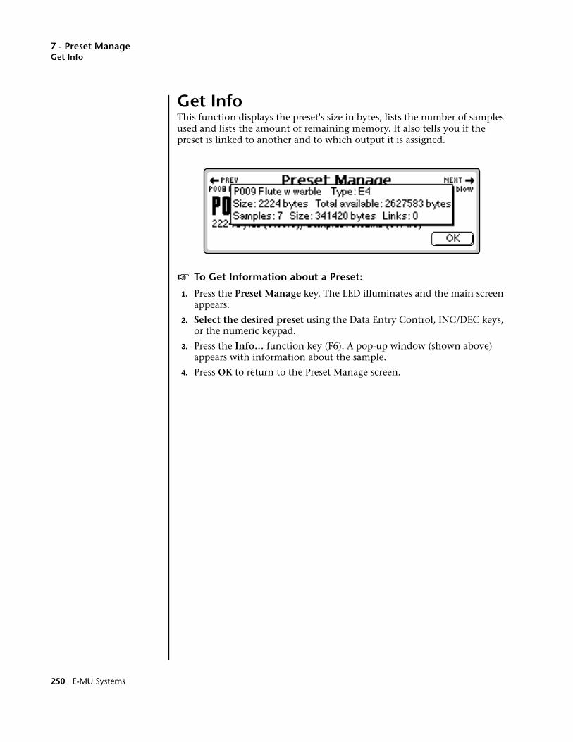
7 - Preset ManageGet Info
Get InfoThis function displays the preset's size in bytes, lists the number of samples used and lists the amount of remaining memory. It also tells you if the preset is linked to another and to which output it is assigned.
v To Get Information about a Preset:
1. Press the Preset Manage key. The LED illuminates and the main screen appears.
2. Select the desired preset using the Data Entry Control, INC/DEC keys, or the numeric keypad.
3. Press the Info… function key (F6). A pop-up window (shown above) appears with information about the sample.
4. Press OK to return to the Preset Manage screen.
250 E-MU Systems
8 - Preset Edit
88Preset Edit
EOS 4.0 Software Manual 251

8 - Preset Edit
252 E-MU Systems
8 - Preset EditEditing Presets
Synthesizer Basics
This chapter explains how preset sounds are constructed. It also contains important background information on the various programming aspects of the instrument.
If you are new to synthesizers and electronic music, you may need more background information than this manual provides. There are many books dedicated to synthesizer basics and MIDI available through your local music dealer. Magazines such as Keyboard and Electronic Musician, which are available at most newsstands, contain current information on the subject, as well as valuable programming tips.
Your initial involvement with the Emulator will most likely consist of using the existing presets and selecting MIDI channels. While the factory banks and presets are very good, there are probably some things you would like to change, perhaps the LFO speed, the filter brightness, or the attack time. You may also want to make your own custom presets using complex modulation routings.
Editing PresetsIt’s easy to create new presets by using the Preset Edit menu to modify existing presets. This is really the best way of getting acquainted with the Emulator. If you don't like the results, simply reload the preset and you'll be back to the original sound. Changes are not made permanent until you SAVE a bank. Therefore, you can experiment all you want with presets, voices and samples without worrying about losing a sound.
We encourage you to actually try out the different functions as you read about them. Hearing what a control actually does will remove a lot of the mystery associated with it.
The Emulator has an extensive modulation implementation using two multi-wave LFO’s (Low Frequency Oscillators), three envelope generators, and the ability to respond to multiple MIDI performance controllers. You can simultaneously route any combination of these control sources to multiple destinations.
EOS 4.0 Software Manual 253

8 - Preset EditModulation
ModulationModulation means to dynamically change a parameter, whether it be the volume (amplitude modulation), the pitch (frequency modulation), or whatever. Turning the volume control on your home stereo rapidly back and forth would be an example of amplitude modulation. To modulate something we need a modulation source and a modulation destination. The source is your hand turning the knob, and the destination is the volume control. If we had a device that would automatically turn the volume control, we would also call that device a modulation source.
Turning the volume control back and forth on your home stereo is an example of Amplitude Modulation.
The Emulator is designed so that for each of the variable parameters, such as the volume, there is an initial setting which can be changed by a modulation source. Therefore in the case of volume, we have an initial volume and we can change or modulate that volume with a modulation source. Positive modulation Adds to the initial amount. Negative modulation Subtracts from the initial amount.
254 E-MU Systems
8 - Preset EditModulation
Modulation SourcesThe main modulation sources are Envelope Generators, Performance Controllers and Low Frequency Oscillators. In the previous example, an envelope generator could be routed to automatically turn the volume control as programmed by the envelope, or, a low frequency oscillator could be routed to turn the volume control up and down in a repeating fashion. The main mod sources are listed below.
Keyboard KeyWhich key is pressed.
Key VelocityHow fast the key is pressed.
Release VelocityHow fast the key is released.
GateHigh if the key is pressed, low when the key is released.
Key GlideA smoothly changing control source based on the Glide Rate and the interval between the last two notes played.
Pitch and Mod WheelsSynthesizer pitch bend and modulation wheels.
Keyboard Pressure (mono aftertouch)Key Pressure applied after the key is initially pressed.
PedalA continuously variable pedal controller.
Miscellaneous Controllers A -HAny type of MIDI continuous controller data.
Low Frequency Oscillators (2 per voice)Generate repeating waves.
Envelope Generators (3 per voice)Generate a programmable “contour” which changes over time when a key is pressed.
Noise & Random GeneratorsGenerate spectrums of noise and random signals.
Thumby Button and Footswitches Change a parameter when the switch is pressed.
EOS 4.0 Software Manual 255

8 - Preset EditModulation
Modulation CordsYou use a Cord to connect a modulation Source to a Destination. (Patchcord – a holdover from the days when modules of an analog synthe-sizer were connected together with physical cords. Nowadays, we still need a way to connect modules together, but the cords are in software.)
You can connect the modulation sources in almost any possible way to the modulation destinations. You can even modulate other modulators. Each cord also has an amount parameter which determines “how much” modulation is applied to the destination. The modulation amount can be positive or negative and will either add or subtract from the initial value.
To use a modulation cord, you must connect a modulation Source to a modulation Destination. Think of it as if you are connecting an actual cord. You must connect both ends of the cord for the cord to work. There are 24 general purpose cords per voice.
ModulationSource
LFO 1
DestinationAmount +/-
AmpVolume
ModulationSource
LFO 1LFO 2
Amp EnvFilt EnvAux EnvWheel
Pressureetc.
Amp VolPitchPan
LFO RateAux EnvEnv Atk
Glideetc.
Destination
- +
256 E-MU Systems
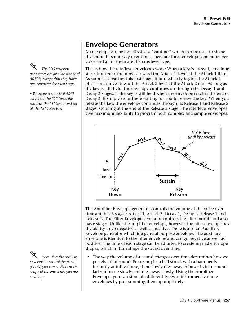
8 - Preset EditEnvelope Generators
Envelope GeneratorsAn envelope can be described as a “contour” which can be used to shape the sound in some way over time. There are three envelope generators per voice and all of them are the rate/level type.
OOOO The EOS envelope generators are just like standard ADSR’s, except that they have two segments for each stage.
• To create a standard ADSR curve, set the “2” levels the same as the “1” levels and set all the “2” rates to 0.
This is how the rate/level envelopes work: When a key is pressed, envelope starts from zero and moves toward the Attack 1 Level at the Attack 1 Rate. As soon as it reaches this first stage, it immediately begins the Attack 2 phase and moves toward the Attack 2 level at the Attack 2 rate. As long as the key is still held, the envelope continues on through the Decay 1 and Decay 2 stages. If the key is still held when the envelope reaches the end of Decay 2, it simply stops there waiting for you to release the key. When you release the key, the envelope continues through its Release 1 and Release 2 stages, stopping at the end of the Release 2 stage. The rate/level envelopes give maximum flexibility to program both complex and simple envelopes.
The Amplifier Envelope generator controls the volume of the voice over time and has 6 stages: Attack 1, Attack 2, Decay 1, Decay 2, Release 1 and Release 2. The Filter Envelope generator controls the filter morph and also has 6 stages. Unlike the amplifier envelope, however, the filter envelope has the ability to go negative as well as positive. There is also an Auxiliary Envelope generator which is a general purpose envelope. The auxiliary envelope is identical to the filter envelope and can go negative as well as positive. The time of each stage can be adjusted to create myriad envelope shapes, which in turn shape the sound over time.
OOOO By routing the Auxiliary Envelope to control the pitch (Cords) you can easily hear the shape of the envelopes you are creating.
• The way the volume of a sound changes over time determines how we perceive that sound. For example, a bell struck with a hammer is instantly at full volume, then slowly dies away. A bowed violin sound fades in more slowly and dies away slowly. Using the Amplifier Envelope, you can simulate different types of instrument volume envelopes by programming them appropriately.
Atk1
Atk2 Dcy1
Dcy2Rls1
Rls2
KeyDown
KeyReleased
Sustaintime
level
Holds hereuntil key release
EOS 4.0 Software Manual 257
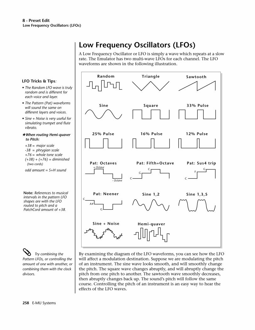
8 - Preset EditLow Frequency Oscillators (LFOs)
Low Frequency Oscillators (LFOs)A Low Frequency Oscillator or LFO is simply a wave which repeats at a slow rate. The Emulator has two multi-wave LFOs for each channel. The LFO waveforms are shown in the following illustration.
Try combining the Pattern LFOs, or controlling the amount of one with another, or combining them with the clock divisors.
By examining the diagram of the LFO waveforms, you can see how the LFO will affect a modulation destination. Suppose we are modulating the pitch of an instrument. The sine wave looks smooth, and will smoothly change the pitch. The square wave changes abruptly, and will abruptly change the pitch from one pitch to another. The sawtooth wave smoothly decreases, then abruptly changes back up. The sound’s pitch will follow the same course. Controlling the pitch of an instrument is an easy way to hear the effects of the LFO waves.
Triangle
Square
Sine 1,2 Sine 1,3,5
Sine
Sawtooth
25% Pulse
33% Pulse
12% Pulse16% Pulse
Random
Pat: Fifth+Octave
C
CG
Pat: Octaves+ Octave
- OctaveC
FG
Pat: Sus4 trip
C
G
A#
Pat: Neener
Hemi-quaver Sine + Noise
LFO Tricks & Tips:
• The Random LFO wave is truly random and is different for each voice and layer.
• The Pattern (Pat) waveforms will sound the same on different layers and voices.
• Sine + Noise is very useful for simulating trumpet and flutevibrato.
★When routing Hemi-quaver to Pitch:
+38 = major scale-38 = phrygian scale+76 = whole tone scale(+38) + (+76) = diminished (two cords)
odd amount = S+H sound
Note: References to musical intervals in the pattern LFO shapes are with the LFO routed to pitch and a PatchCord amount of +38.
258 E-MU Systems
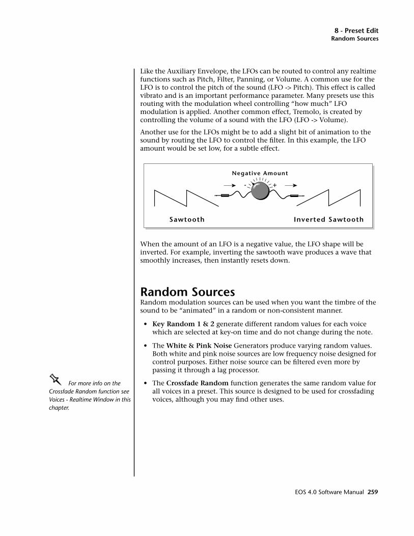
8 - Preset EditRandom Sources
Like the Auxiliary Envelope, the LFOs can be routed to control any realtime functions such as Pitch, Filter, Panning, or Volume. A common use for the LFO is to control the pitch of the sound (LFO -> Pitch). This effect is called vibrato and is an important performance parameter. Many presets use this routing with the modulation wheel controlling “how much” LFO modulation is applied. Another common effect, Tremolo, is created by controlling the volume of a sound with the LFO (LFO -> Volume).
Another use for the LFOs might be to add a slight bit of animation to the sound by routing the LFO to control the filter. In this example, the LFO amount would be set low, for a subtle effect.
When the amount of an LFO is a negative value, the LFO shape will be inverted. For example, inverting the sawtooth wave produces a wave that smoothly increases, then instantly resets down.
Random SourcesRandom modulation sources can be used when you want the timbre of the sound to be “animated” in a random or non-consistent manner.
• Key Random 1 & 2 generate different random values for each voice which are selected at key-on time and do not change during the note.
• The White & Pink Noise Generators produce varying random values. Both white and pink noise sources are low frequency noise designed for control purposes. Either noise source can be filtered even more by passing it through a lag processor.
OOOO For more info on the Crossfade Random function see Voices - Realtime Window in this chapter.
• The Crossfade Random function generates the same random value for all voices in a preset. This source is designed to be used for crossfading voices, although you may find other uses.
Inverted Sawtooth
Negative Amount
+-
Sawtooth
EOS 4.0 Software Manual 259

8 - Preset EditClock Modulation
Clock ModulationThe Sequencer/Arpeggiator clock can also be used as a modulation source. It can be used to trigger the Filter or Auxiliary envelope generators, trigger Sample Start, synchronize the LFOs, or used directly as a square wave modulation source. Envelopes are triggered on the positive going edge of the clock. LFOs are triggered on the negative going edge.
The Clock source is available in six divisions (double whole note, whole note, half note, quarter note, eighth note, sixteenth note). The different rates can be used separately or in conjunction to create complex “synchro-sonic” rhythm patterns.
Using MIDI clocks, Sequencer/Arpeggiator clock can also be synchronized with an external MIDI device such as a drum machine or sequencer.
Clocks are routed exactly like the other modulations sources using the Cords. The Cord Amount MUST be positive (+) for the clock to pass. By modulating the Cord Amount, the divided clocks can be routed around using realtime controllers or other modulation sources.
Syncing an LFO to the ClockWhen an LFO is triggered by a clock, the LFO wave resets to zero every time the clock wave goes low. To sync an LFO to the clock, patch a clock divisor to the LFO Trigger (Trg) in the Cords screen.
If the LFO rate is close to the clock rate, the LFO will synchronize with the clock. If the two rates are far apart, the waveform of the LFO will be mildly or radically altered (as shown below).
LFO Trigger causes the LFO to reset each time the clock waveform goes low.
The possibilities of clock modulation and retrigger are numerous and varied. A repeating six segment curve of any shape can be created by triggering the Filter or Auxiliary Envelope generators with the clock.
Clock
LFO Wave
Triggered LFO
260 E-MU Systems
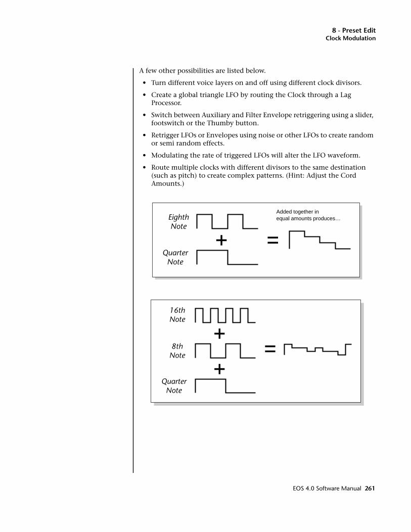
8 - Preset EditClock Modulation
A few other possibilities are listed below.
• Turn different voice layers on and off using different clock divisors.
• Create a global triangle LFO by routing the Clock through a Lag Processor.
• Switch between Auxiliary and Filter Envelope retriggering using a slider, footswitch or the Thumby button.
• Retrigger LFOs or Envelopes using noise or other LFOs to create random or semi random effects.
• Modulating the rate of triggered LFOs will alter the LFO waveform.
• Route multiple clocks with different divisors to the same destination (such as pitch) to create complex patterns. (Hint: Adjust the Cord Amounts.)
QuarterNote
EighthNote
Added together in equal amounts produces…
QuarterNote
8thNote
16thNote
EOS 4.0 Software Manual 261
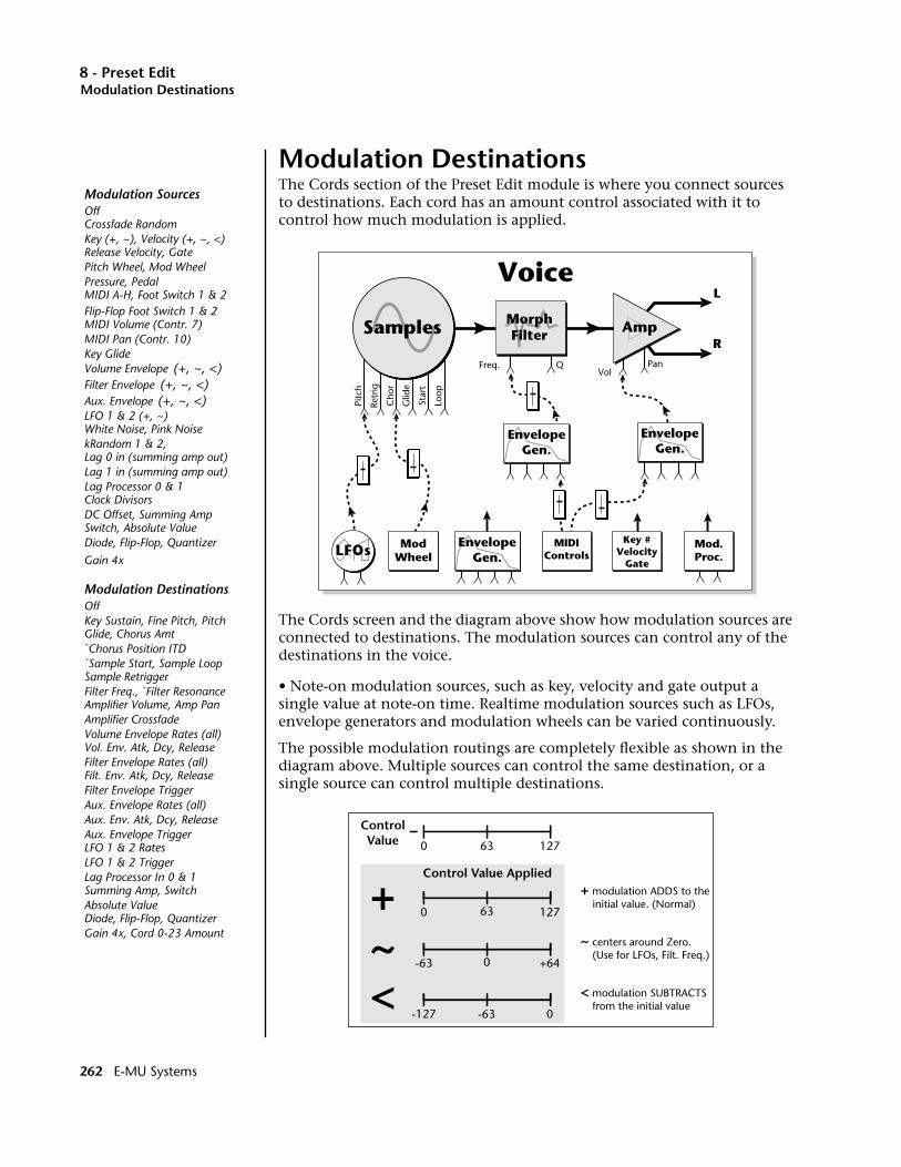
8 - Preset EditModulation Destinations
Modulation DestinationsThe Cords section of the Preset Edit module is where you connect sources to destinations. Each cord has an amount control associated with it to control how much modulation is applied.
The Cords screen and the diagram above show how modulation sources are connected to destinations. The modulation sources can control any of the destinations in the voice.
• Note-on modulation sources, such as key, velocity and gate output a single value at note-on time. Realtime modulation sources such as LFOs, envelope generators and modulation wheels can be varied continuously.
The possible modulation routings are completely flexible as shown in the diagram above. Multiple sources can control the same destination, or a single source can control multiple destinations.
Samples Amp
L
R
EnvelopeGen.
Freq. QVol
Pitc
h
Retr
ig
Glid
e
Star
t
Loop
Cho
r
Pan
Voice
MorphFilter
EnvelopeGen.
EnvelopeGen.LFOs Mod
WheelMIDI
ControlsMod.Proc.
Key #Velocity
Gate
+~
+ modulation ADDS to the initial value. (Normal)
< modulation SUBTRACTS from the initial value
~ centers around Zero. (Use for LFOs, Filt. Freq.)
ControlValue
Control Value Applied
0 12763
0 12763
-63 +640
-127 0-63<
Modulation SourcesOffCrossfade RandomKey (+, ~), Velocity (+, ~, <)Release Velocity, GatePitch Wheel, Mod WheelPressure, PedalMIDI A-H, Foot Switch 1 & 2Flip-Flop Foot Switch 1 & 2MIDI Volume (Contr. 7)MIDI Pan (Contr. 10)Key GlideVolume Envelope (+, ~, <)Filter Envelope (+, ~, <)Aux. Envelope (+, ~, <)LFO 1 & 2 (+, ~)White Noise, Pink NoisekRandom 1 & 2,Lag 0 in (summing amp out)Lag 1 in (summing amp out)Lag Processor 0 & 1Clock DivisorsDC Offset, Summing AmpSwitch, Absolute ValueDiode, Flip-Flop, Quantizer
Gain 4x
Modulation DestinationsOffKey Sustain, Fine Pitch, PitchGlide, Chorus Amt`Chorus Position ITD`Sample Start, Sample LoopSample RetriggerFilter Freq., `Filter ResonanceAmplifier Volume, Amp PanAmplifier CrossfadeVolume Envelope Rates (all)Vol. Env. Atk, Dcy, ReleaseFilter Envelope Rates (all)Filt. Env. Atk, Dcy, ReleaseFilter Envelope TriggerAux. Envelope Rates (all)Aux. Env. Atk, Dcy, ReleaseAux. Envelope TriggerLFO 1 & 2 RatesLFO 1 & 2 TriggerLag Processor In 0 & 1Summing Amp, SwitchAbsolute ValueDiode, Flip-Flop, QuantizerGain 4x, Cord 0-23 Amount
262 E-MU Systems
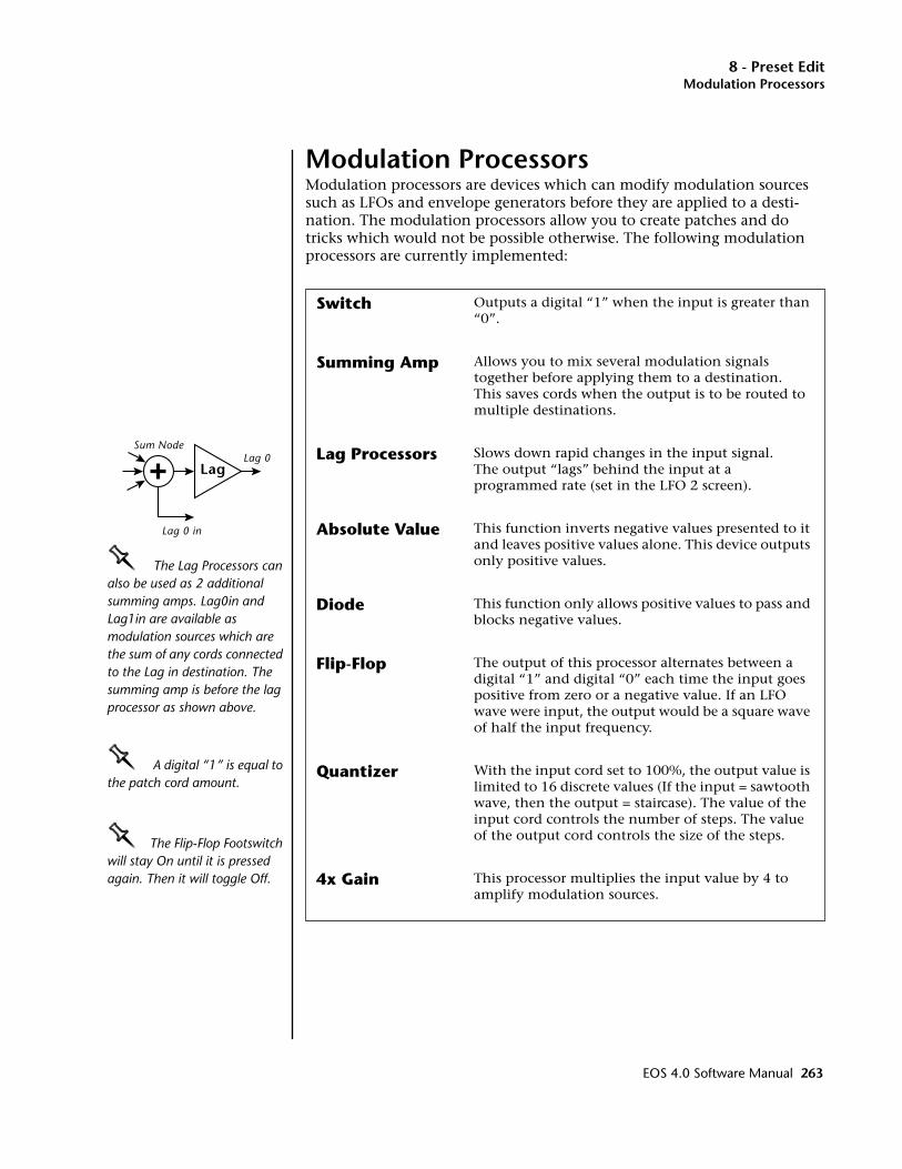
8 - Preset EditModulation Processors
Modulation ProcessorsModulation processors are devices which can modify modulation sources such as LFOs and envelope generators before they are applied to a desti-nation. The modulation processors allow you to create patches and do tricks which would not be possible otherwise. The following modulation processors are currently implemented:
Switch Outputs a digital “1” when the input is greater than “0”.
Summing Amp Allows you to mix several modulation signals together before applying them to a destination. This saves cords when the output is to be routed to multiple destinations.
Lag Processors Slows down rapid changes in the input signal. The output “lags” behind the input at a programmed rate (set in the LFO 2 screen).
Absolute Value This function inverts negative values presented to it and leaves positive values alone. This device outputs only positive values.
Diode This function only allows positive values to pass and blocks negative values.
Flip-Flop The output of this processor alternates between a digital “1” and digital “0” each time the input goes positive from zero or a negative value. If an LFO wave were input, the output would be a square wave of half the input frequency.
Quantizer With the input cord set to 100%, the output value is limited to 16 discrete values (If the input = sawtooth wave, then the output = staircase). The value of the input cord controls the number of steps. The value of the output cord controls the size of the steps.
4x Gain This processor multiplies the input value by 4 to amplify modulation sources.
OOOO The Lag Processors can also be used as 2 additional summing amps. Lag0in and Lag1in are available as modulation sources which are the sum of any cords connected to the Lag in destination. The summing amp is before the lag processor as shown above.
OOOO A digital “1” is equal to the patch cord amount.
OOOO The Flip-Flop Footswitch will stay On until it is pressed again. Then it will toggle Off.
Lag
Sum Node
Lag 0 in
Lag 0
EOS 4.0 Software Manual 263
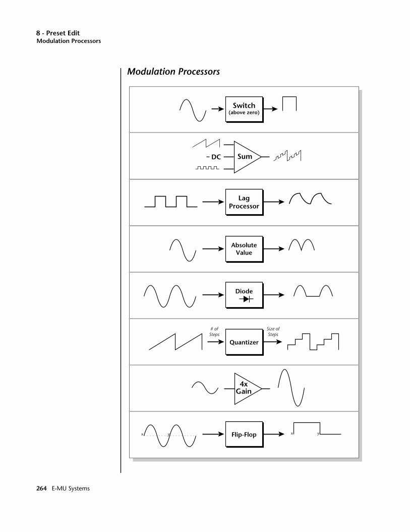
8 - Preset EditModulation Processors
Modulation Processors
4xGain
AbsoluteValue
Flip-Flopx y x y
Diode
LagProcessor
Quantizer
# ofSteps
Size ofSteps
SumDC
Switch(above zero)
264 E-MU Systems
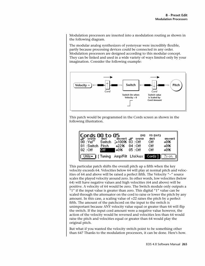
8 - Preset EditModulation Processors
Modulation processors are inserted into a modulation routing as shown in the following diagram.
The modular analog synthesizers of yesteryear were incredibly flexible, partly because processing devices could be connected in any order. Modulation processors are designed according to this modular concept. They can be linked and used in a wide variety of ways limited only by your imagination. Consider the following example:
This patch would be programmed in the Cords screen as shown in the following illustration.
This particular patch shifts the overall pitch up a fifth when the key velocity exceeds 64. Velocities below 64 will play at normal pitch and veloc-ities of 64 and above will be raised a perfect fifth. The Velocity “~” source scales the played velocity around zero. In other words, low velocities (below 64) will have negative values and high velocities (64 and above) will be positive. A velocity of 64 would be zero. The Switch module only outputs a “1” if the input value is greater than zero. This digital “1” value can be scaled through the attenuator on the cord to raise or lower the pitch by any amount. In this case, a scaling value of +22 raises the pitch by a perfect fifth. The amount of the patchcord on the input to the switch is unimportant because ANY velocity value equal or greater than 64 will flip the switch. If the input cord amount were a negative value however, the action of the velocity would be reversed and velocities less than 64 would raise the pitch and velocities equal or greater than 64 would play the original pitch.
But what if you wanted the velocity switch point to be something other than 64? Thanks to the modulation processors, it can be done. Here's how.
SwitchVelocity ~ Pitch
Cord CordSwitch On when
Velocity > 0Switch valueis Scaled by
Cord Amount
EOS 4.0 Software Manual 265
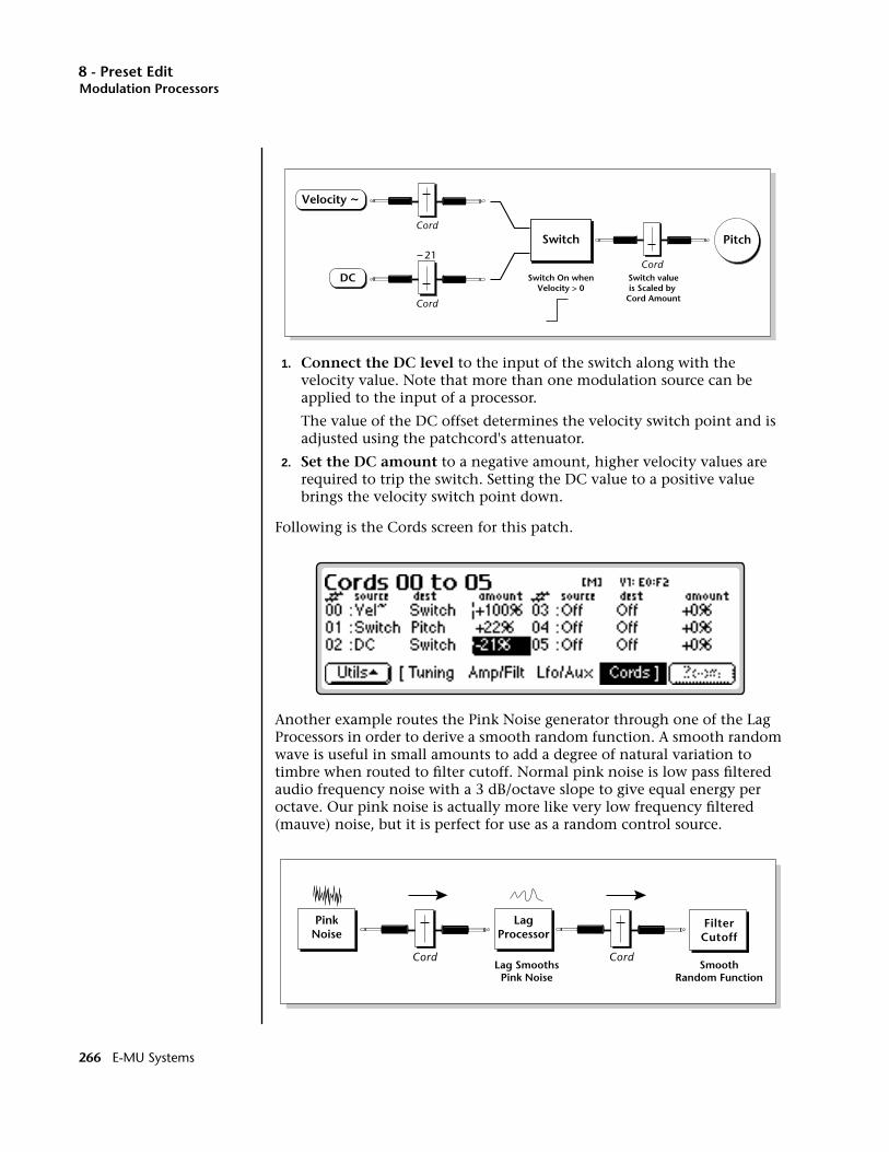
8 - Preset EditModulation Processors
1. Connect the DC level to the input of the switch along with the velocity value. Note that more than one modulation source can be applied to the input of a processor.
The value of the DC offset determines the velocity switch point and is adjusted using the patchcord's attenuator.
2. Set the DC amount to a negative amount, higher velocity values are required to trip the switch. Setting the DC value to a positive value brings the velocity switch point down.
Following is the Cords screen for this patch.
Another example routes the Pink Noise generator through one of the Lag Processors in order to derive a smooth random function. A smooth random wave is useful in small amounts to add a degree of natural variation to timbre when routed to filter cutoff. Normal pink noise is low pass filtered audio frequency noise with a 3 dB/octave slope to give equal energy per octave. Our pink noise is actually more like very low frequency filtered (mauve) noise, but it is perfect for use as a random control source.
Switch
Velocity ~
PitchCord
Cord
21Cord
Switch On whenVelocity > 0
Switch valueis Scaled by
Cord Amount
DC
LagProcessor
PinkNoise
FilterCutoff
Cord CordLag Smooths
Pink NoiseSmooth
Random Function
266 E-MU Systems
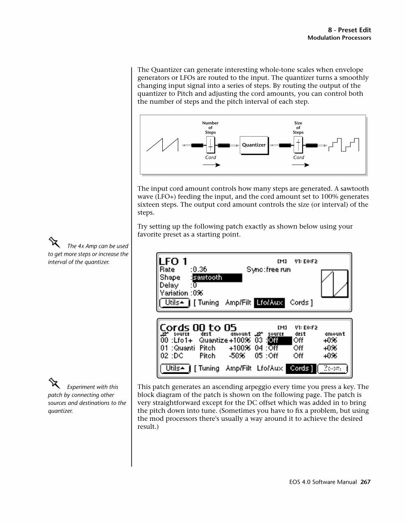
8 - Preset EditModulation Processors
The Quantizer can generate interesting whole-tone scales when envelope generators or LFOs are routed to the input. The quantizer turns a smoothly changing input signal into a series of steps. By routing the output of the quantizer to Pitch and adjusting the cord amounts, you can control both the number of steps and the pitch interval of each step.
The input cord amount controls how many steps are generated. A sawtooth wave (LFO+) feeding the input, and the cord amount set to 100% generates sixteen steps. The output cord amount controls the size (or interval) of the steps.
Try setting up the following patch exactly as shown below using your favorite preset as a starting point.
OOOO The 4x Amp can be used to get more steps or increase the interval of the quantizer.
OOOO Experiment with this patch by connecting other sources and destinations to the quantizer.
This patch generates an ascending arpeggio every time you press a key. The block diagram of the patch is shown on the following page. The patch is very straightforward except for the DC offset which was added in to bring the pitch down into tune. (Sometimes you have to fix a problem, but using the mod processors there's usually a way around it to achieve the desired result.)
Quantizer
Numberof
Steps
Sizeof
Steps
Cord Cord
EOS 4.0 Software Manual 267
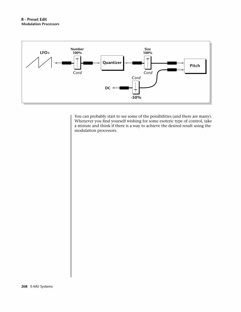
8 - Preset EditModulation Processors
You can probably start to see some of the possibilities (and there are many). Whenever you find yourself wishing for some esoteric type of control, take a minute and think if there is a way to achieve the desired result using the modulation processors.
QuantizerPitch
Number100%LFO+
DC
Size100%
Cord CordCord
-50%
268 E-MU Systems
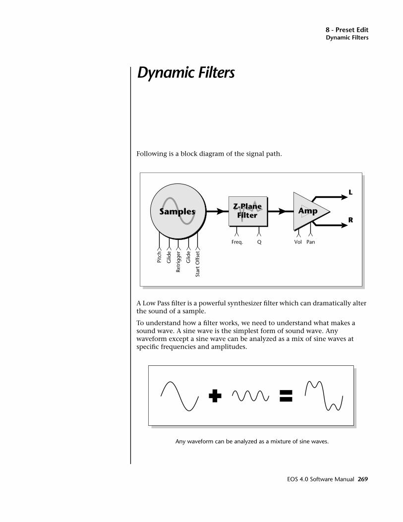
8 - Preset EditDynamic Filters
Dynamic Filters
Dynamic FiltersFollowing is a block diagram of the signal path.
A Low Pass filter is a powerful synthesizer filter which can dramatically alter the sound of a sample.
To understand how a filter works, we need to understand what makes a sound wave. A sine wave is the simplest form of sound wave. Any waveform except a sine wave can be analyzed as a mix of sine waves at specific frequencies and amplitudes.
Any waveform can be analyzed as a mixture of sine waves.
Samples Amp
L
R
Freq. VolQ
Retr
igge
r
Pitc
h
Glid
e
Glid
e
Star
t O
ffset
Pan
Z-PlaneFilter
EOS 4.0 Software Manual 269

8 - Preset EditDynamic Filters
One way to represent complex waveforms is to use a chart with frequency on one axis and amplitude on the other. Each vertical line of the chart represents one sine wave at a specific amplitude and frequency.
What is a Filter? Most samples are complex waves containing many sine waves of various amplitudes and frequencies. A filter is a device which allows us to remove certain components of a sound depending on its frequency. For example, a Low Pass Filter lets the low frequencies pass and removes only the high frequencies.
20
40
60
80
100
40 80 160 360 720 1440 2880
Frequency...
Am
pli
tud
e
Frequency vs Amplitude
20
40
60
80
100
40 80 160 360 720 1440 2880
Frequency...
Am
pli
tud
e
Cutoff Frequency
Output of Filter Low PassFilter
270 E-MU Systems

8 - Preset EditDynamic Filters
A filter that lets only the high frequencies pass is called a high-pass filter.
A filter that only lets a certain band of frequencies pass is called a band-pass filter.
A Notch Filter is just the opposite of a bandpass filter and is used to eliminate a narrow band of frequencies.
Another control found on traditional filters is called Q or resonance. A lowpass filter with a high Q would emphasize the frequencies around the cutoff frequency. The following chart shows how different amounts of Q affect the low pass filter response. In terms of sound, frequencies around the cutoff tend to “ring” with high Q settings. If the filter is slowly swept back and forth, with a high Q, various overtones are “picked out” of the sound and amplified as the resonant peak sweeps over them. Bells and gongs are real world examples of sounds which have a high Q.
20
40
60
80
100
40 80 160 360 720 1440 2880
Frequency...
Am
plit
ude Filter Output
Initial Frequency
High PassFilter
20
40
60
80
100
40 80 160 360 720 1440 2880
Frequency...
Am
plit
ude
Center Frequency
FilterOutput
Band PassFilter
EOS 4.0 Software Manual 271
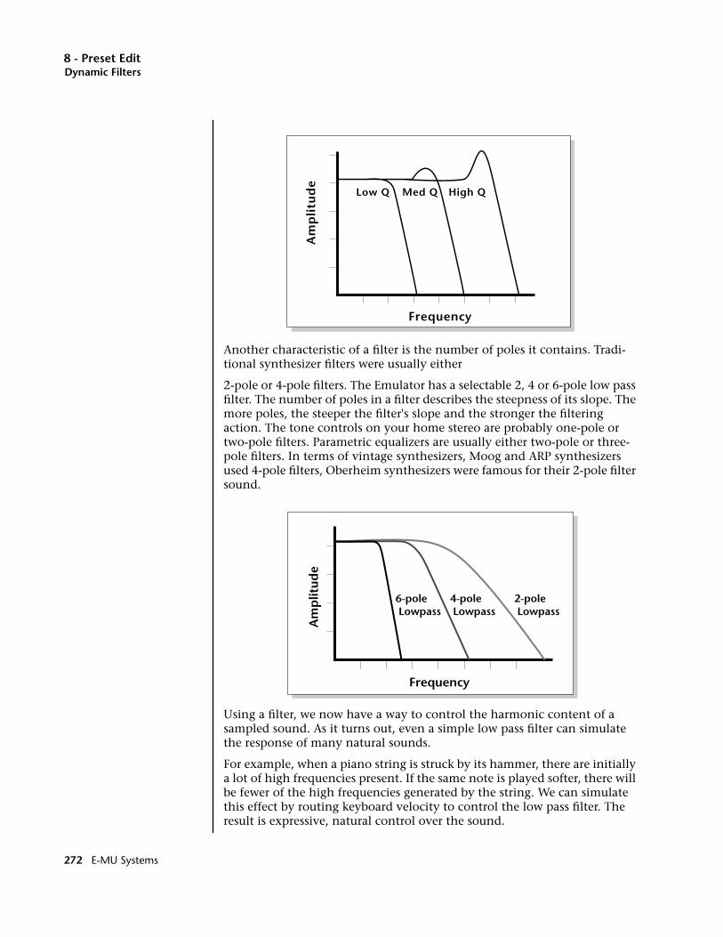
8 - Preset EditDynamic Filters
Another characteristic of a filter is the number of poles it contains. Tradi-tional synthesizer filters were usually either
2-pole or 4-pole filters. The Emulator has a selectable 2, 4 or 6-pole low pass filter. The number of poles in a filter describes the steepness of its slope. The more poles, the steeper the filter's slope and the stronger the filtering action. The tone controls on your home stereo are probably one-pole or two-pole filters. Parametric equalizers are usually either two-pole or three-pole filters. In terms of vintage synthesizers, Moog and ARP synthesizers used 4-pole filters, Oberheim synthesizers were famous for their 2-pole filter sound.
Using a filter, we now have a way to control the harmonic content of a sampled sound. As it turns out, even a simple low pass filter can simulate the response of many natural sounds.
For example, when a piano string is struck by its hammer, there are initially a lot of high frequencies present. If the same note is played softer, there will be fewer of the high frequencies generated by the string. We can simulate this effect by routing keyboard velocity to control the low pass filter. The result is expressive, natural control over the sound.
FrequencyA
mp
litu
de
Low Q Med Q High Q
Frequency
Am
plit
ude
4-pole Lowpass
6-pole Lowpass
2-pole Lowpass
272 E-MU Systems
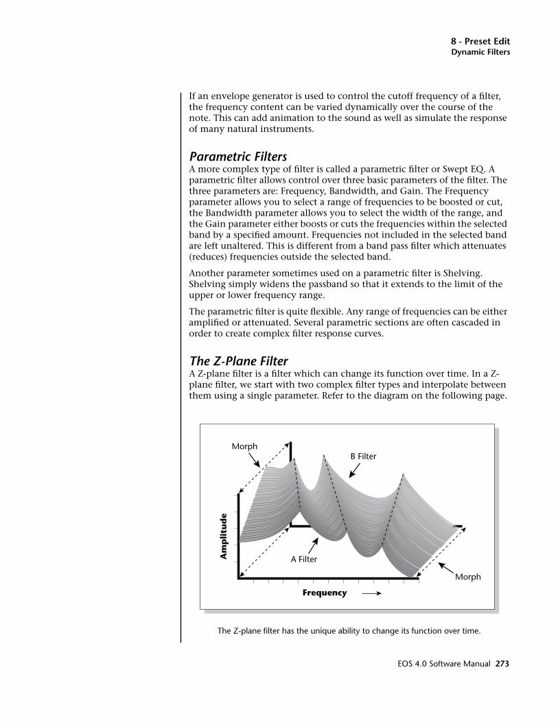
8 - Preset EditDynamic Filters
If an envelope generator is used to control the cutoff frequency of a filter, the frequency content can be varied dynamically over the course of the note. This can add animation to the sound as well as simulate the response of many natural instruments.
Parametric FiltersA more complex type of filter is called a parametric filter or Swept EQ. A parametric filter allows control over three basic parameters of the filter. The three parameters are: Frequency, Bandwidth, and Gain. The Frequency parameter allows you to select a range of frequencies to be boosted or cut, the Bandwidth parameter allows you to select the width of the range, and the Gain parameter either boosts or cuts the frequencies within the selected band by a specified amount. Frequencies not included in the selected band are left unaltered. This is different from a band pass filter which attenuates (reduces) frequencies outside the selected band.
Another parameter sometimes used on a parametric filter is Shelving. Shelving simply widens the passband so that it extends to the limit of the upper or lower frequency range.
The parametric filter is quite flexible. Any range of frequencies can be either amplified or attenuated. Several parametric sections are often cascaded in order to create complex filter response curves.
The Z-Plane FilterA Z-plane filter is a filter which can change its function over time. In a Z-plane filter, we start with two complex filter types and interpolate between them using a single parameter. Refer to the diagram on the following page.
The Z-plane filter has the unique ability to change its function over time.
Frequency
Am
pli
tud
e
Morph
Morph
B Filter
A Filter
EOS 4.0 Software Manual 273
8 - Preset EditDynamic Filters
Filters A and B represent two different complex filters or “frames”. By changing a single parameter, the Morph, many complex filter parameters can now be changed simultaneously. Following along the Morph axis you can see that the filter response smoothly interpolates between the two filters. This is the essence of the Z-plane filter. Through the use of interpo-lation, many complex parameters are condensed down into one manageable entity.
Consider, as an example, the human vocal tract, which is a type of complex filter or resonator. There are dozens of different muscles controlling the shape of the vocal tract. When speaking, however, we don't think of the muscles, we just remember how it feels to form the vowels. A vowel is really a configuration of many muscles, but we consider it a single object. In changing from one vowel to another, we don't need to consider the frequencies of the resonant peaks! You remember the shape of your mouth for each sound and interpolate between them.
This Z-plane filter sweep can be controlled by an envelope generator, an LFO, modulation wheels or pedals, keyboard velocity, key pressure, etc. In fact, any of the modulation sources can control the Z-plane filter.
274 E-MU Systems

8 - Preset EditSelecting Voices, Samples & Groups
Selecting Voices, Samples & Groups
When working on complex sounds we need an easy way to specify certain voices or groups of voices for editing. There are several ways to select Voices, Samples and Groups.
Selecting from the Preset Editor WindowsTo select Voices, Groups, or Samples from any of the preset editor windows you simply move the cursor to the appropriate field and press the Edit key (F6). The label on the Edit key changes depending on which type of item the cursor is on.
• When the cursor is on any Voice-related Function, the Edit key will select Voice Edit.
• When the cursor is on the Group Number, the Edit key will select the entire Group.
• When the cursor is on the Sample Name, the Edit key will select the Sample and will automatically jump into the Sample Edit menu.
Here's another little trick to help you select voices from the Preset Editor Windows.
• Press and Hold the decimal point button while playing a keyboard key to select that voice. Repeatedly pressing the keyboard key will rotate through any other voices assigned to that same key.
EOS 4.0 Software Manual 275

8 - Preset EditSelecting All Voices
Selecting All VoicesIn many cases, you will want to select the entire keyboard. An easy way to Select All is to go to the Preset Globals page.
v To Select all Voices1. Press the Preset Edit button
2. Press the Global function key (F3).
3. Press the Edit All function key (F6). You have just selected all voices.
Selecting Voices from the Dynamic Processing LevelFor power users, there is an automatic voice selection mode which selects voices whenever you play the keyboard.
v To turn Automatic Voice Selection On:1. Press the Preset Edit button
2. Press the Edit function key (F6).
3. Press the Utils function key (F1).OOOO The Preset Edit screens can be confusing because the module is divided into two parts (Preset Definition and Dynamic Processing). If you get confused, Exit the module and follow the steps shown.
4. Press the VSelect function key (F1).
5. Press the Auto function key (F3).
6. Press the OK function key (F6).
• Selecting a single note will select all voices assigned to that key.
• Selecting a keyboard range by pressing two notes at once will select all voices within that range.
Now a few Words of Caution: When you play the keyboard to hear the results of your edit, YOU ARE CHANGING THE VOICE SELECTION RANGE! This can be confusing unless you remember to re-key the voice selection range before resuming editing.
Selecting Voices from the Voice Select ScreenThere is also a special Voice Selection screen located in the Utilities menu of the Dynamic Processing level.
v To Access the Voice Select Screen:1. Press the Preset Edit button.
2. Press the Edit function key (F6).
3. Press the Utils function key (F1).
4. Press the VSelect function key (F1).
276 E-MU Systems
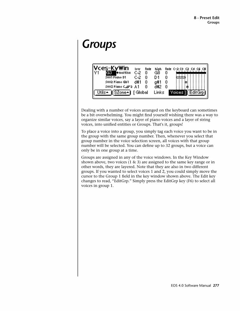
8 - Preset EditGroups
Groups
Dealing with a number of voices arranged on the keyboard can sometimes be a bit overwhelming. You might find yourself wishing there was a way to organize similar voices, say a layer of piano voices and a layer of string voices, into unified entities or Groups. That's it, groups!
To place a voice into a group, you simply tag each voice you want to be in the group with the same group number. Then, whenever you select that group number in the voice selection screen, all voices with that group number will be selected. You can define up to 32 groups, but a voice can only be in one group at a time.
Groups are assigned in any of the voice windows. In the Key Window shown above, two voices (1 & 3) are assigned to the same key range or in other words, they are layered. Note that they are also in two different groups. If you wanted to select voices 1 and 2, you could simply move the cursor to the Group 1 field in the key window shown above. The Edit key changes to read, “EditGrp.” Simply press the EditGrp key (F6) to select all voices in group 1.
EOS 4.0 Software Manual 277
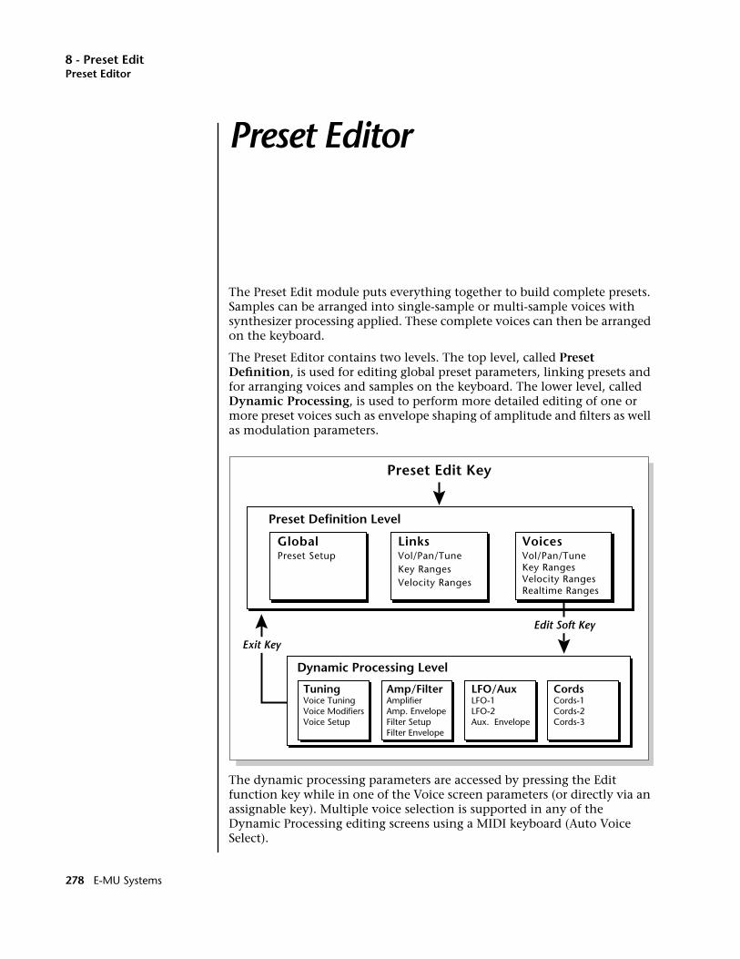
8 - Preset EditPreset Editor
Preset Editor
The Preset Edit module puts everything together to build complete presets. Samples can be arranged into single-sample or multi-sample voices with synthesizer processing applied. These complete voices can then be arranged on the keyboard.
The Preset Editor contains two levels. The top level, called Preset Definition, is used for editing global preset parameters, linking presets and for arranging voices and samples on the keyboard. The lower level, called Dynamic Processing, is used to perform more detailed editing of one or more preset voices such as envelope shaping of amplitude and filters as well as modulation parameters.
The dynamic processing parameters are accessed by pressing the Edit function key while in one of the Voice screen parameters (or directly via an assignable key). Multiple voice selection is supported in any of the Dynamic Processing editing screens using a MIDI keyboard (Auto Voice Select).
Preset Edit Key
GlobalPreset Setup
LinksVol/Pan/TuneKey RangesVelocity Ranges
VoicesVol/Pan/TuneKey RangesVelocity RangesRealtime Ranges
TuningVoice TuningVoice ModifiersVoice Setup
Amp/FilterAmplifierAmp. EnvelopeFilter SetupFilter Envelope
LFO/AuxLFO-1LFO-2Aux. Envelope
CordsCords-1Cords-2Cords-3
Dynamic Processing Level
Preset Definition Level
Exit Key
Edit Soft Key
278 E-MU Systems
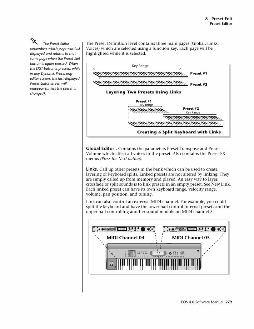
8 - Preset EditPreset Editor
OOOO The Preset Editor remembers which page was last displayed and returns to that same page when the Preset Edit button is again pressed. When the EXIT button is pressed, while in any Dynamic Processing editor screen, the last-displayed Preset Editor screen will reappear (unless the preset is changed).
The Preset Definition level contains three main pages (Global, Links, Voices) which are selected using a function key. Each page will be highlighted while it is selected.
Global Editor . Contains the parameters Preset Transpose and Preset Volume which affect all voices in the preset. Also contains the Preset FX menus (Press the Next button).
Links. Call up other presets in the bank which can be used to create layering or keyboard splits. Linked presets are not altered by linking. They are simply called up from memory and played. An easy way to layer, crossfade or split sounds is to link presets in an empty preset. See New Link. Each linked preset can have its own keyboard range, velocity range, volume, pan position, and tuning.
Link can also control an external MIDI channel. For example, you could split the keyboard and have the lower half control internal presets and the upper half controlling another sound module on MIDI channel 5.
Preset #1
Preset #2
Layering Two Presets Using Links
Key Range
Preset #1
Preset #2Key Range
Key Range
Creating a Split Keyboard with Links
EOS 4.0 Software Manual 279
8 - Preset EditPreset Editor
This is called a MIDI Link. MIDI Links can be assigned to any keyboard range or can be scaled according to velocity. This allows you to use the E4K as a Master Controller keyboard and split or layer the keyboard up to 16 ways with a different synthesizer on each MIDI channel.
OOOO MIDI Links re-transmit data received on the Emulator's Basic MIDI Channel (Master, MIDI).
On an Emulator rack unit, MIDI Links can process and re-output incoming MIDI data from your keyboard. This allows any MIDI keyboard to become a Master keyboard with multiple split points and layering.
Voice Editing. Allows you to place voices and samples on the keyboard and crossfade or switch between them according to key position, velocity range and realtime control range. This submodule also contains parameters to adjust the tuning, volume and pan position for the voices and samples.
If a voice contains more than one sample, it will be labeled as a multi-sample and the individual samples will be listed below it. Voices are shown graphically as solid black bars and samples are shown as empty bars. If a voice contains only one sample, then the sample will be the voice name.
PostScript error (invalidfont, findfont)
280 E-MU Systems
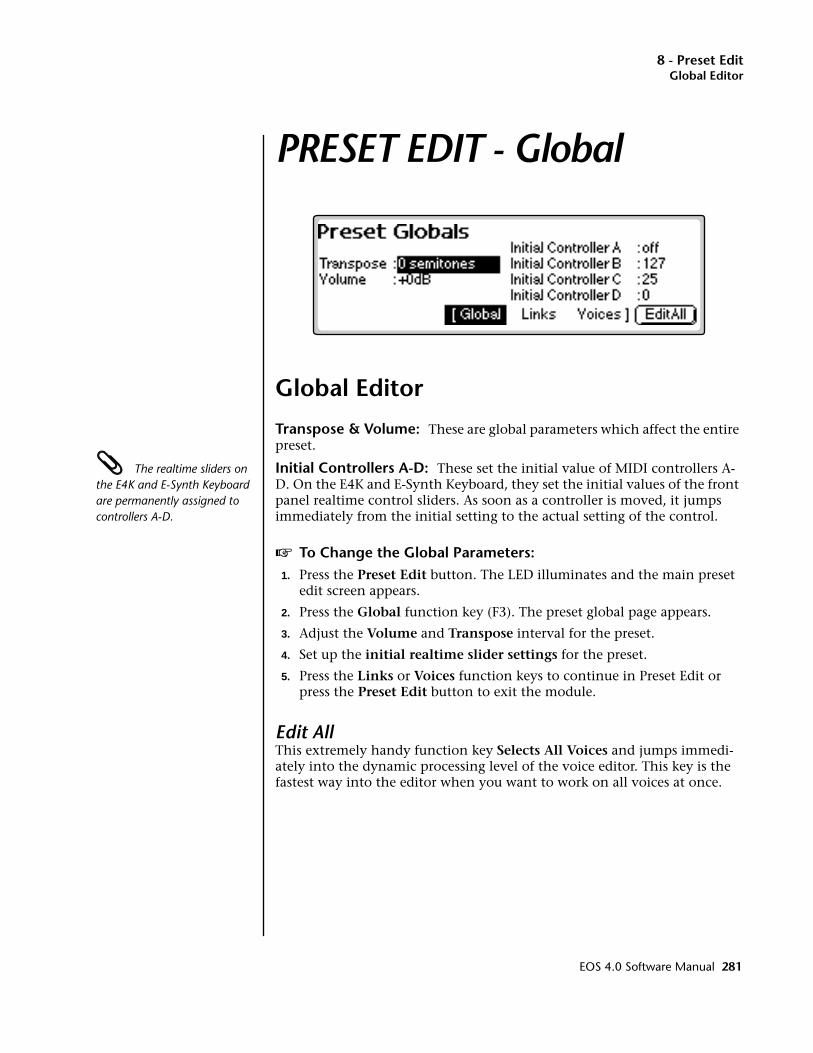
8 - Preset EditGlobal Editor
PRESET EDIT - Global
Global Editor
Transpose & Volume: These are global parameters which affect the entire preset.
The realtime sliders on the E4K and E-Synth Keyboard are permanently assigned to controllers A-D.
Initial Controllers A-D: These set the initial value of MIDI controllers A-D. On the E4K and E-Synth Keyboard, they set the initial values of the front panel realtime control sliders. As soon as a controller is moved, it jumps immediately from the initial setting to the actual setting of the control.
v To Change the Global Parameters:1. Press the Preset Edit button. The LED illuminates and the main preset
edit screen appears.
2. Press the Global function key (F3). The preset global page appears.
3. Adjust the Volume and Transpose interval for the preset.
4. Set up the initial realtime slider settings for the preset.
5. Press the Links or Voices function keys to continue in Preset Edit or press the Preset Edit button to exit the module.
Edit AllThis extremely handy function key Selects All Voices and jumps immedi-ately into the dynamic processing level of the voice editor. This key is the fastest way into the editor when you want to work on all voices at once.
EOS 4.0 Software Manual 281
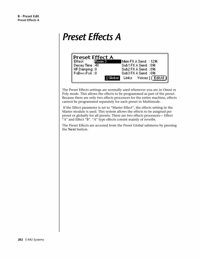
8 - Preset EditPreset Effects A
Preset Effects A
The Preset Effects settings are normally used whenever you are in Omni or Poly mode. This allows the effects to be programmed as part of the preset. Because there are only two effects processors for the entire machine, effects cannot be programmed separately for each preset in Multimode.
If the Effect parameter is set to “Master Effect”, the effects setting in the Master module is used. This system allows the effects to be assigned per preset or globally for all presets. There are two effects processors— Effect “A” and Effect “B”. “A” type effects consist mainly of reverbs.
The Preset Effects are accessed from the Preset Global submenu by pressing the Next button.
282 E-MU Systems
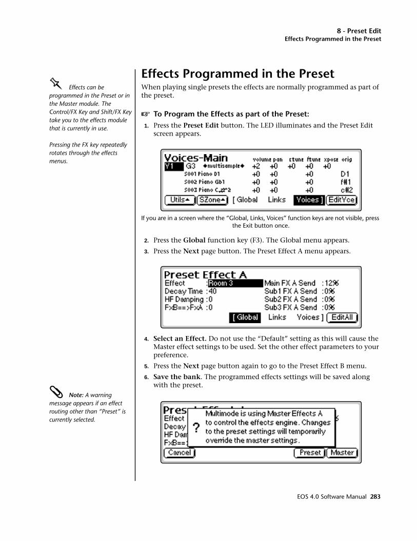
8 - Preset EditEffects Programmed in the Preset
Effects Programmed in the PresetOOOO Effects can be programmed in the Preset or in the Master module. The Control/FX Key and Shift/FX Key take you to the effects module that is currently in use.
Pressing the FX key repeatedly rotates through the effects menus.
When playing single presets the effects are normally programmed as part of the preset.
v To Program the Effects as part of the Preset:1. Press the Preset Edit button. The LED illuminates and the Preset Edit
screen appears.
If you are in a screen where the “Global, Links, Voices” function keys are not visible, press the Exit button once.
2. Press the Global function key (F3). The Global menu appears.
3. Press the Next page button. The Preset Effect A menu appears.
4. Select an Effect. Do not use the “Default” setting as this will cause the Master effect settings to be used. Set the other effect parameters to your preference.
5. Press the Next page button again to go to the Preset Effect B menu.
6. Save the bank. The programmed effects settings will be saved along with the preset.
Note: A warning message appears if an effect routing other than “Preset” is currently selected.
EOS 4.0 Software Manual 283
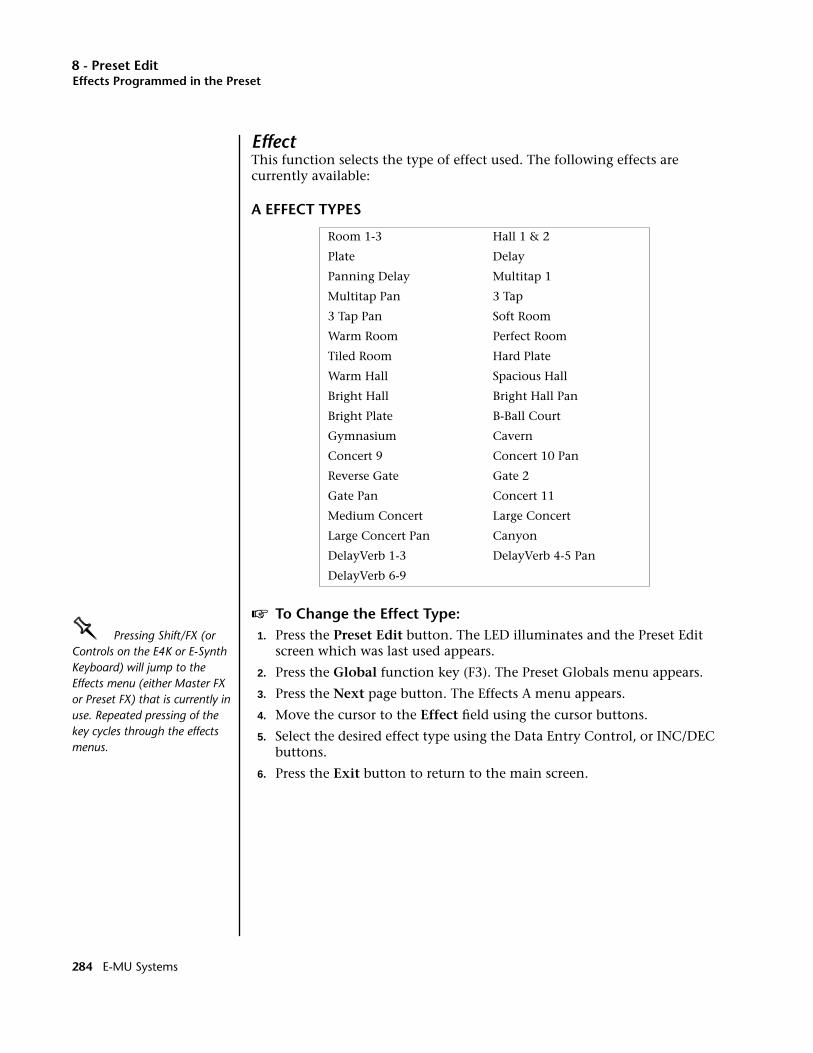
8 - Preset EditEffects Programmed in the Preset
EffectThis function selects the type of effect used. The following effects are currently available:
A EFFECT TYPES
v To Change the Effect Type:OOOO Pressing Shift/FX (or Controls on the E4K or E-Synth Keyboard) will jump to the Effects menu (either Master FX or Preset FX) that is currently in use. Repeated pressing of the key cycles through the effects menus.
1. Press the Preset Edit button. The LED illuminates and the Preset Edit screen which was last used appears.
2. Press the Global function key (F3). The Preset Globals menu appears.
3. Press the Next page button. The Effects A menu appears.
4. Move the cursor to the Effect field using the cursor buttons.
5. Select the desired effect type using the Data Entry Control, or INC/DEC buttons.
6. Press the Exit button to return to the main screen.
Room 1-3 Hall 1 & 2
Plate Delay
Panning Delay Multitap 1
Multitap Pan 3 Tap
3 Tap Pan Soft Room
Warm Room Perfect Room
Tiled Room Hard Plate
Warm Hall Spacious Hall
Bright Hall Bright Hall Pan
Bright Plate B-Ball Court
Gymnasium Cavern
Concert 9 Concert 10 Pan
Reverse Gate Gate 2
Gate Pan Concert 11
Medium Concert Large Concert
Large Concert Pan Canyon
DelayVerb 1-3 DelayVerb 4-5 Pan
DelayVerb 6-9
284 E-MU Systems

8 - Preset EditEffects Programmed in the Preset
Decay TimeThis parameter sets the length of time it will take an effect to fade away. In the case of reverb, decay time controls the room size and the reflectivity of the room. On a delay effect, decay time controls how many echoes are produced or how long the echoes will last.
v To Change the Decay Time:1. Press the Preset Edit button. The LED illuminates and the Preset Edit
screen which was last used appears.
2. Press the Global function key (F3). The Preset Globals menu appears.
3. Press the Next page button. The Effects A menu appears.
4. Move the cursor to the Decay Time field using the cursor buttons.
5. Set the Decay Time using the Data Entry Control, or INC/DEC buttons.
6. Press the Exit button to return to the main screen.
HF DampingHigh frequency energy tends to fade away first as a sound is dissipated in a room. This parameter allows you adjust the amount of high frequency damping and thus change the characteristics of the room. Rooms with smooth, hard surfaces are more reflective and have less high frequency damping. Rooms filled with sound absorbing materials such as curtains or people have more high frequency damping.
v To Change the High Frequency Damping:1. Press the Preset Edit button. The LED illuminates and the Preset Edit
screen which was last used appears.
2. Press the Global function key (F3). The Preset Globals menu appears.
3. Press the Next page button. The Effects A menu appears.
4. Move the cursor to the HF Damping field using the cursor buttons.
5. Adjust the HF Damping parameter using the Data Entry Control, or INC/DEC buttons.
6. Press the Exit button to return to the main screen.
FX AmountsThe Effects Amount controls the percentage of effected (wet) signal to un-effected (dry) signal. This function would be analogous to the effect sends on a mixing console. The effects amount for each of the four stereo outputs can be individually controlled.
v To Change the Effects Amount:1. Press the Preset Edit button. The LED illuminates and the Preset Edit
screen which was last used appears.
EOS 4.0 Software Manual 285
8 - Preset EditEffects Programmed in the Preset
2. Press the Global function key (F3). The Preset Globals menu appears.
3. Press the Next page button. The Effects A menu appears.
4. Move the cursor to the desired FX Amount field using the cursor buttons.
5. Adjust the FX Amount using the Data Entry Control, or INC/DEC buttons.
6. Press the Exit button to return to the main screen.
FX B Through FX AThe output of effect processor B can be routed into effect processor A. This connects the effects in series instead of their normal parallel configuration. The BflA amount can also be controlled for even more flexibility.
v To Send the Output of Effect B through Effect A:In this example, 100% of Effect B will be sent into Effect A.
1. The Effect A screen (in either the Master or Preset Edit menus) contains the B–>A Amount parameter. Set this amount to 100%.
2. Turn the Send Amounts down to zero since we only want to hear the two effects in series.
3. Press the Next page button to select Effect B. Select an effect and adjust the Main FX B Send percentage as desired.
4. Play the keyboard and you should hear the B Effect running through Effect A.
See chapter 3 - Effects for more information.
286 E-MU Systems
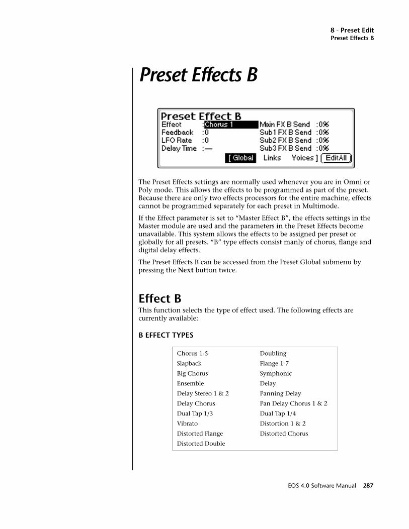
8 - Preset EditPreset Effects B
Preset Effects B
The Preset Effects settings are normally used whenever you are in Omni or Poly mode. This allows the effects to be programmed as part of the preset. Because there are only two effects processors for the entire machine, effects cannot be programmed separately for each preset in Multimode.
If the Effect parameter is set to “Master Effect B”, the effects settings in the Master module are used and the parameters in the Preset Effects become unavailable. This system allows the effects to be assigned per preset or globally for all presets. “B” type effects consist manly of chorus, flange and digital delay effects.
The Preset Effects B can be accessed from the Preset Global submenu by pressing the Next button twice.
Effect BThis function selects the type of effect used. The following effects are currently available:
B EFFECT TYPES
Chorus 1-5 Doubling
Slapback Flange 1-7
Big Chorus Symphonic
Ensemble Delay
Delay Stereo 1 & 2 Panning Delay
Delay Chorus Pan Delay Chorus 1 & 2
Dual Tap 1/3 Dual Tap 1/4
Vibrato Distortion 1 & 2
Distorted Flange Distorted Chorus
Distorted Double
EOS 4.0 Software Manual 287
8 - Preset EditEffect B
v To Change the Effect Type:1. Press the Preset Edit button. The LED illuminates and the Preset Edit
screen which was last used appears.
2. Press the Global function key (F3). The Preset Globals menu appears.
3. Press the Next page key twice. The Effects B menu appears.
OOOO See chapter 3, FX for detailed information on the effects.
• Alternate Method: Pressing Shift/FX (or Controls on the E4K) will jump to the Effects menu (either Master FX or Preset FX) that is cur-rently in use. Repeated pressing of the key cycles through the effects menus.
4. Move the cursor to the Effect field using the cursor buttons.
5. Select the desired effect type using the Data Entry Control, or INC/DEC buttons.
6. Press the Exit button to return to the main screen.
Feedback AmountThe Chorus and Flange effects have a controllable feedback loop after the delay element. Feeding back a small amount of the signal intensifies the effect by creating multiple cancellations or images.
v To Change the Feedback Amount:1. Press the Preset Edit button. The LED illuminates and the Preset Edit
screen which was last used appears.
2. Press the Global function key (F3). The Preset Globals menu appears.
3. Press the Next page button twice. The Effects B menu appears.
4. Move the cursor to the desired Feedback Amount field using the cursor buttons.
5. Adjust the Feedback Amount using the Data Entry Control, or INC/DEC buttons.
6. Press the Exit button to return to the main screen.
288 E-MU Systems

8 - Preset EditEffect B
LFO RateChorus and flange effects use a Low Frequency Oscillator to animate the effect. LFO applied to a chorus effect creates the slight changes necessary for a realistic choral effect. Applied to a flanger, the LFO moves the comb filter notches and adds animation to the sound.
v To Change the LFO Rate:1. Press the Preset Edit button. The LED illuminates and the Preset Edit
screen which was last used appears.
2. Press the Global function key (F3). The Preset Globals menu appears.
3. Press the Next page key twice. The Effects B menu appears.
4. Move the cursor to the LFO Rate field using the cursor buttons.
5. Set the LFO Rate using the Data Entry Control, or INC/DEC buttons.
6. Press the Exit button to return to the main screen.
Delay TimeFlanging, chorus and echoes are all based on a delay line where the signal is delayed by some time period and mixed back together with it's un-delayed signal. This parameter varies the length of the delay or “how much time” passes before you hear the delayed signal. On some effects, this parameter is not adjustable, indicated by a dash in the field.
v To Change the Delay Time:1. Press the Master button. The LED illuminates and the Memory
Statistics screen appears.
2. Press the Output function key (F4). The Output menu appears.
3. Press the Next page button twice. The Effects B menu appears.
4. Move the cursor to Delay Time using the cursor buttons.
5. Adjust the Delay Time parameter using the Data Entry Control, or INC/DEC buttons.
6. Press Exit to return to the main screen.
EOS 4.0 Software Manual 289
8 - Preset EditEffect B
FX AmountsThe Effects Amount controls the percentage of effected (wet) signal to un-effected (dry) signal. This function would be analogous to the effect sends on a mixing console. The effects amount for each of the four stereo outputs can be individually controlled.
v To Change the Effects Amount:1. Press the Preset Edit button. The LED illuminates and the Preset Edit
screen which was last used appears.
2. Press the Global function key (F3). The Preset Globals menu appears.
3. Press the Next page key twice. The Effects B menu appears.
4. Move the cursor to the desired FX Amount field using the cursor buttons.
5. Adjust the FX Amount using the Data Entry Control, or INC/DEC buttons.
6. Press the Exit button to return to the main screen.
290 E-MU Systems

8 - Preset EditPreset Edit - Links
Preset Edit - Links
Main Controls
Link Field: Link can be selected using the numeric keypad or Data Entry Control. A Link can be an internal preset or an external MIDI device. A MIDI Program Change command will also be sent if it is a MIDI LInk.
Link Preset Name & Number: The linked preset can be changed using the Data Entry Control or INC/DEC buttons.
Link Controls: These controls offset the volume, pan, transpose and fine tuning controls of the linked preset.
Utilities: New, Delete, Copy, and Subsume.
LinkField
Link Presetname & number
Link Typeinternal/external
Link ControlsVolume, Pan, Coarse/Fine Tuning
DisplaysGlobal Editor Pages
New - adds link to presetDelete - deletes link from presetCopy - copies link to any presetSubsume - copies voices of the linked preset into the current preset.
DisplaysVoice Editor Pages
Button is highlightedwhile this page set
is displayed.
Use the Page keysto access the Key &Velocity windows.
ExternalLink
EOS 4.0 Software Manual 291
8 - Preset EditLink Type
Link TypeLinks can be made to one or more internal presets or to one or more external MIDI devices.
____ MIDI Links can only be used in Omni or Poly modes.
MIDI Links allow your keyboard to control up to 16 external MIDI devices with multiple split points and layers. When a MIDI Link is selected, the preset field selects a MIDI program change which will be transmitted (on the selected MIDI channel) when the preset is first selected.
v To Change the Link Type:1. Press the Preset Edit button. The LED illuminates and the last page
selected appears.OOOO On an Emulator Rack Unit, MIDI LInks can filter and re-transmit data received on the Basic MIDI Channel.
This allows any MIDI keyboard to become a powerful master controller.
2. Press the Links function key (F4) to select the link page of the editor. The link function key will be highlighted.
3. Use the Cursor buttons to select the “Link Type” field. If there are no Links in the preset, you can create one using the New Utility.
4. Set the “Type” parameter to internal or to external MIDI channel using the Data Entry Control or INC/DEC buttons.
5. Use the Cursor buttons to select other Link parameters.
6. Press the Exit button to return to the main preset selection screen.
Link VolumeThis function allows you to adjust the volume of the linked preset relative to the main preset. When a MIDI Link is selected an initial volume message (Channel Volume - Controller 7) will be transmitted when the preset is selected.
The internal values of -96 to +10 are scaled to correspond to MIDI volume values. A value of +10 corresponds to MIDI Volume 127 and -96 corre-sponds to MIDI volume 0.
v To Change the Link Volume:1. Press the Preset Edit button. The LED illuminates and the last page
selected appears.
2. Press the Links function key (F4) to select the link page of the editor. The link function key will be highlighted.
3. Use the Cursor buttons to select the Volume field. If there are no Links in the preset, you can create one using the New Utility.
4. Change the Volume parameter to the desired value using the Data Entry Control or the INC/DEC buttons.
5. Use the Cursor buttons to select other Link parameters or press the Exit button to return to the main preset selection screen.
292 E-MU Systems
8 - Preset EditLink Pan
Link PanThis function allows you to set the left /right pan position for the selected link. When a MIDI Link is selected, an initial pan message (Channel Pan - Controller 10) will be transmitted when the preset is first selected.
v To Change the Link Pan Position:1. Press the Preset Edit button. The LED illuminates and the last page
selected appears.
2. Press the Links function key (F4) to select the link page of the editor. The link function key will be highlighted.
3. Use the Cursor buttons to select the Pan field. If there are no Links in the preset, you can create one using the New Utility.
4. Change the Pan parameter to the desired value using the Data Entry Control or the INC/DEC buttons.
5. Use the Cursor buttons to select other Link parameters or press the Exit button to return to the main preset selection screen.
Link TransposeThis function allows you to transpose the key of the link in semitone intervals by shifting the keyboard position relative to middle C. The transpose range is -24 to +24 semitones. When a MIDI Link is selected, the external MIDI notes are transposed by the selected amount.
v To Transpose a Link:1. Press the Preset Edit button. The LED illuminates and the last page
selected appears.
2. Press the Links function key (F4) to select the link page of the editor. The link function key will be highlighted.
3. Use the Cursor buttons to select the “Xpose” field. If there are no Links in the preset, you can create one using the New Utility.
4. Change the Transpose parameter to the desired value using the Data Entry Control or the INC/DEC buttons.
5. Use the Cursor buttons to select other Link parameters or press the Exit button to return to the main preset selection screen.
EOS 4.0 Software Manual 293
8 - Preset EditLink Fine Tuning
Link Fine TuningThis function allows you to change the tuning of the Linked preset in 1/64 semitone intervals (approx. 1.56 cents). The fine tuning range is ± 1 semitone. Fine tuning can be used to slightly detune a preset, creating a “fatter” sound when it is combined with another preset. This parameter has no effect when a MIDI Link is selected.
v To Fine Tune a Link:1. Press the Preset Edit button. The LED illuminates and the last page
selected appears.
2. Press the Links function key (F4) to select the link page of the editor. The link function key will be highlighted.
3. Use the Cursor buttons to select the “Ftune” field. If there are no Links in the preset, you can create one using the New Utility.
4. Change the Fine Tune parameter to the desired value using the Data Entry Control or the INC/DEC buttons.
5. Use the Cursor buttons to select other Link parameters or press the Exit button to return to the main preset selection screen.
294 E-MU Systems
8 - Preset EditLink Utilities
Link Utilities
New LinkCreates a new link field.
v To Create a New Link:1. Press the Preset Edit button. The LED illuminates and the last page
selected appears.
2. Press the Links function key (F4) to select the link page of the editor. The link function key will be highlighted.
3. Press the Utils function key (F1). A second row of function keys appears.
4. Press the New… function key (F1). A new link field will be added to the list of preset links.
5. Press Exit if you wish to cancel the operation.
v To Create a Huge Stacked Preset the Easy Way:1. Load any bank of presets.
2. Press the Preset Manage button. Press the New key to create a new blank preset.
3. Select a location for the new blank preset and name it if desired.
4. Press the Preset Edit button.
5. Press the Links function key (F4) to select the link page of the editor. The link function key will be highlighted.
6. Press the Utils function key (F1). A second row of function keys appears.
7. Press the New… function key (F2). A new link field will be added to the list of preset links.
8. Move the Cursor to the preset field and select a preset.
9. Repeat steps 6 and 7 until the desired thickness has been achieved.
10. Press Exit to leave the Utilities menu.
EOS 4.0 Software Manual 295
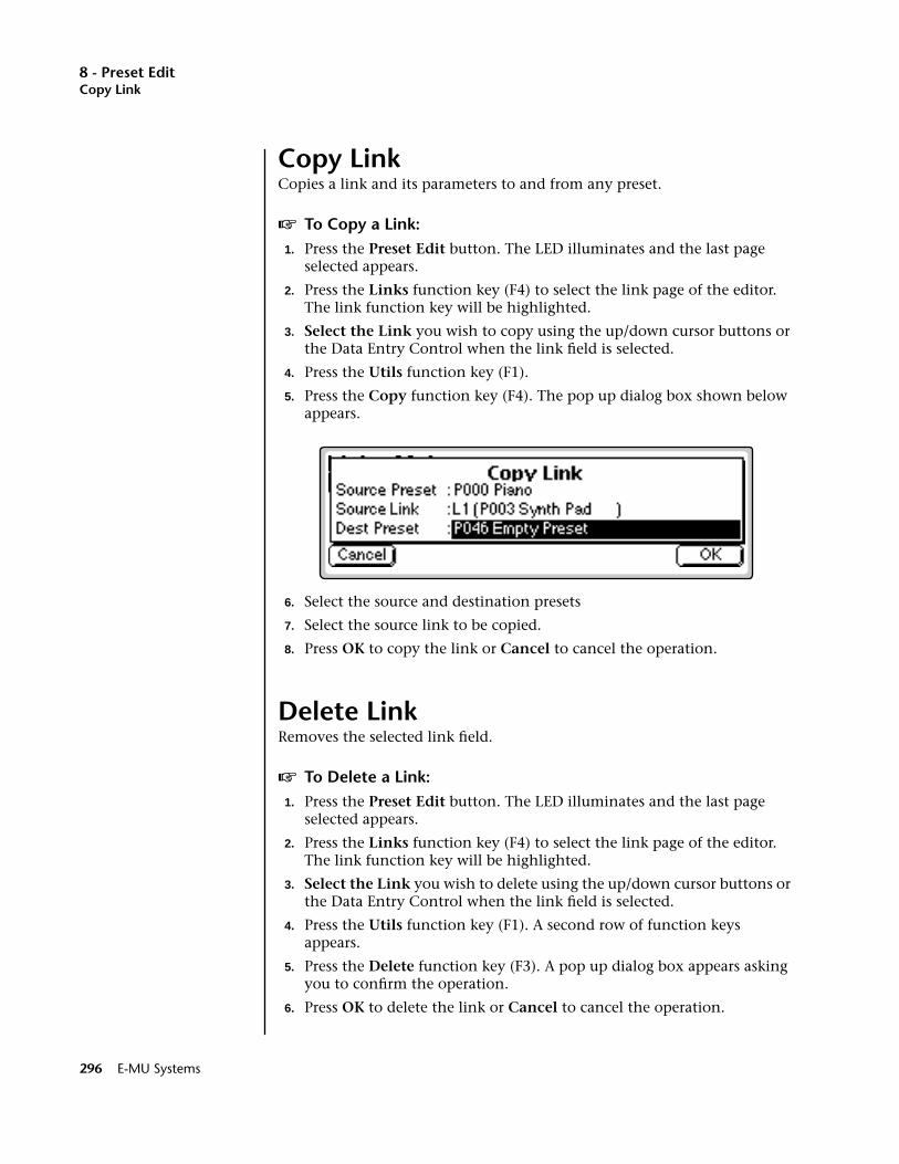
8 - Preset EditCopy Link
Copy LinkCopies a link and its parameters to and from any preset.
v To Copy a Link:1. Press the Preset Edit button. The LED illuminates and the last page
selected appears.
2. Press the Links function key (F4) to select the link page of the editor. The link function key will be highlighted.
3. Select the Link you wish to copy using the up/down cursor buttons or the Data Entry Control when the link field is selected.
4. Press the Utils function key (F1).
5. Press the Copy function key (F4). The pop up dialog box shown below appears.
6. Select the source and destination presets
7. Select the source link to be copied.
8. Press OK to copy the link or Cancel to cancel the operation.
Delete LinkRemoves the selected link field.
v To Delete a Link:1. Press the Preset Edit button. The LED illuminates and the last page
selected appears.
2. Press the Links function key (F4) to select the link page of the editor. The link function key will be highlighted.
3. Select the Link you wish to delete using the up/down cursor buttons or the Data Entry Control when the link field is selected.
4. Press the Utils function key (F1). A second row of function keys appears.
5. Press the Delete function key (F3). A pop up dialog box appears asking you to confirm the operation.
6. Press OK to delete the link or Cancel to cancel the operation.
296 E-MU Systems
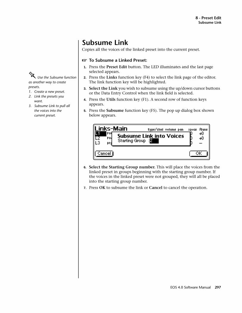
8 - Preset EditSubsume Link
Subsume LinkCopies all the voices of the linked preset into the current preset.
v To Subsume a Linked Preset:1. Press the Preset Edit button. The LED illuminates and the last page
selected appears.OOOO Use the Subsume function as another way to create presets. 1. Create a new preset.2. Link the presets you
want.3. Subsume Link to pull all
the voices into the current preset.
2. Press the Links function key (F4) to select the link page of the editor. The link function key will be highlighted.
3. Select the Link you wish to subsume using the up/down cursor buttons or the Data Entry Control when the link field is selected.
4. Press the Utils function key (F1). A second row of function keys appears.
5. Press the Subsume function key (F5). The pop up dialog box shown below appears.
6. Select the Starting Group number. This will place the voices from the linked preset in groups beginning with the starting group number. If the voices in the linked preset were not grouped, they will all be placed into the starting group number.
7. Press OK to subsume the link or Cancel to cancel the operation.
EOS 4.0 Software Manual 297
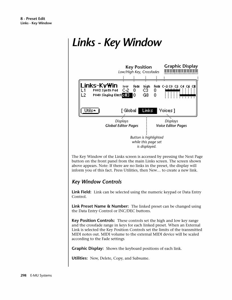
8 - Preset EditLinks - Key Window
Links - Key Window
The Key Window of the Links screen is accessed by pressing the Next Page button on the front panel from the main Links screen. The screen shown above appears. Note: If there are no links in the preset, the display will inform you of this fact. Press Utilities, then New… to create a new link.
Key Window Controls
Link Field: Link can be selected using the numeric keypad or Data Entry Control.
Link Preset Name & Number: The linked preset can be changed using the Data Entry Control or INC/DEC buttons.
Key Position Controls: These controls set the high and low key range and the crossfade range in keys for each linked preset. When an External Link is selected the Key Position Controls set the limits of the transmitted MIDI notes out. MIDI volume to the external MIDI device will be scaled according to the Fade settings
Graphic Display: Shows the keyboard positions of each link.
Utilities: New, Delete, Copy, and Subsume.
Key PositionLow/High Key, Crossfades
Graphic Display
DisplaysGlobal Editor Pages
DisplaysVoice Editor Pages
Button is highlightedwhile this page set
is displayed.
298 E-MU Systems

8 - Preset EditKeyboard & Velocity Ranges
Keyboard & Velocity RangesWhen editing the keyboard and velocity ranges of preset links, an editing screen similar to the one shown on the previous page appears.
The bars at the right side of the screen give a graphic display of how the presets are placed on the keyboard. The key position is edited by placing the cursor over the desired parameter and then playing the MIDI keyboard or adjusting the Data Entry Control.
v To Positionally CrossfadeThe Fade parameters allow the volume of the preset to be faded out as a function of key position. In the Link screen shown below, the two presets are being positionally crossfaded over a range of one octave.
As you play up the keyboard in the C2-C3 octave range, the Synth Pad preset will gradually fade out as the Singing Electric preset fades in. This is shown on the display by the range bars fading out and in.
This technique can help mask the point at which two sounds meet. The presets are assigned so that they overlap by a few keys, then the fades are programmed so that one sound fades out as the other fades in.
Note: Make sure the external devices are set up to respond to MIDI channel volume.
• If two External Links were selected in the example above, using two dif-ferent MIDI channels instead of two different presets, the volumes of the two external devices would be positionally crossfaded over the one octave range between C2 and C3.
EOS 4.0 Software Manual 299
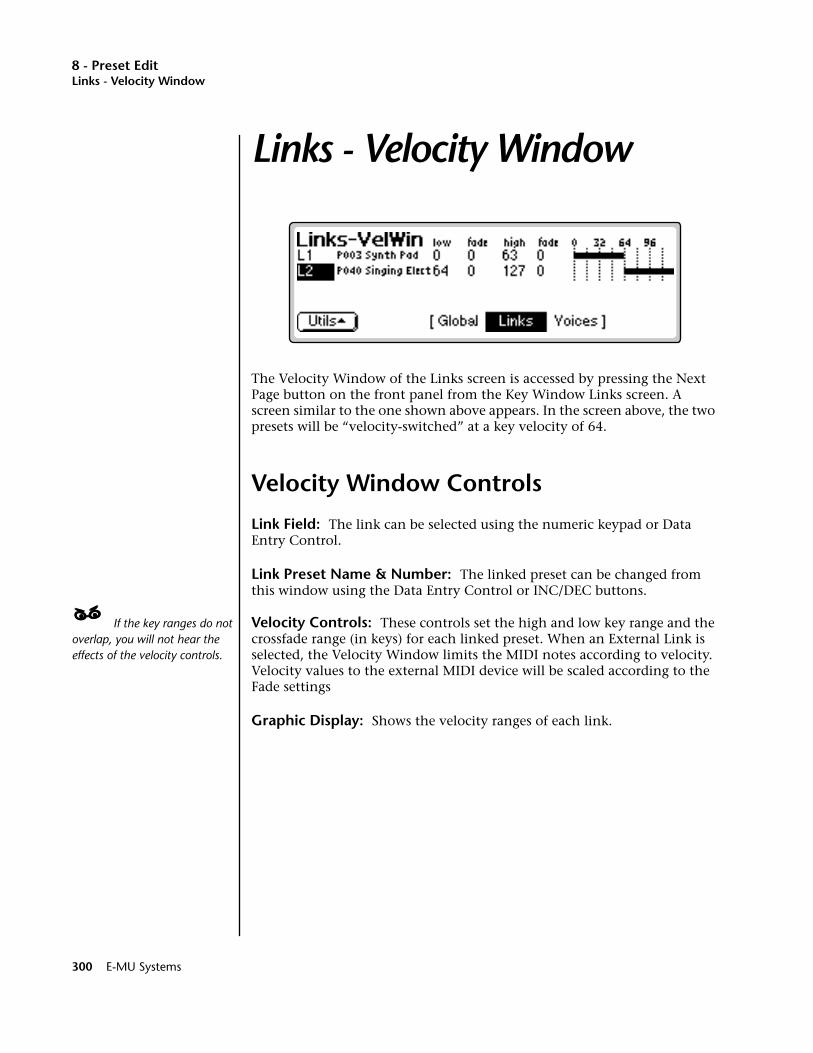
8 - Preset EditLinks - Velocity Window
Links - Velocity Window
The Velocity Window of the Links screen is accessed by pressing the Next Page button on the front panel from the Key Window Links screen. A screen similar to the one shown above appears. In the screen above, the two presets will be “velocity-switched” at a key velocity of 64.
Velocity Window Controls
Link Field: The link can be selected using the numeric keypad or Data Entry Control.
Link Preset Name & Number: The linked preset can be changed from this window using the Data Entry Control or INC/DEC buttons.
____ If the key ranges do not overlap, you will not hear the effects of the velocity controls.
Velocity Controls: These controls set the high and low key range and the crossfade range (in keys) for each linked preset. When an External Link is selected, the Velocity Window limits the MIDI notes according to velocity. Velocity values to the external MIDI device will be scaled according to the Fade settings
Graphic Display: Shows the velocity ranges of each link.
300 E-MU Systems
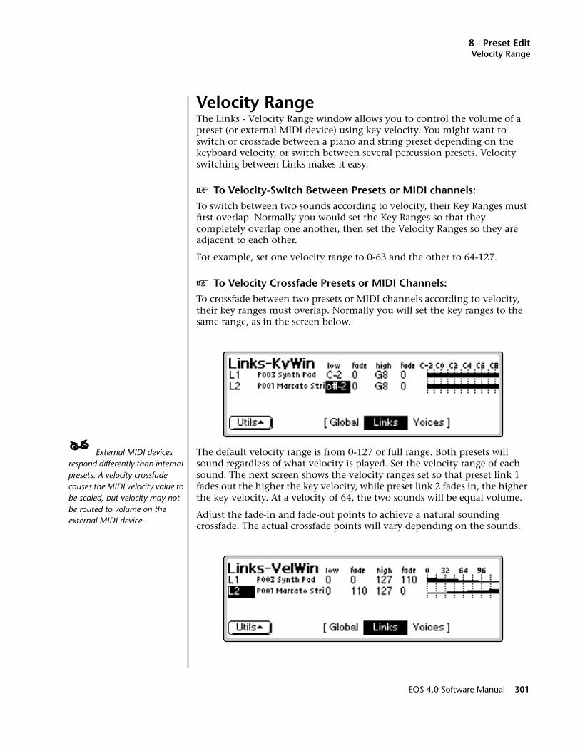
8 - Preset EditVelocity Range
Velocity RangeThe Links - Velocity Range window allows you to control the volume of a preset (or external MIDI device) using key velocity. You might want to switch or crossfade between a piano and string preset depending on the keyboard velocity, or switch between several percussion presets. Velocity switching between Links makes it easy.
v To Velocity-Switch Between Presets or MIDI channels:To switch between two sounds according to velocity, their Key Ranges must first overlap. Normally you would set the Key Ranges so that they completely overlap one another, then set the Velocity Ranges so they are adjacent to each other.
For example, set one velocity range to 0-63 and the other to 64-127.
v To Velocity Crossfade Presets or MIDI Channels:To crossfade between two presets or MIDI channels according to velocity, their key ranges must overlap. Normally you will set the key ranges to the same range, as in the screen below.
____ External MIDI devices respond differently than internal presets. A velocity crossfade causes the MIDI velocity value to be scaled, but velocity may not be routed to volume on the external MIDI device.
The default velocity range is from 0-127 or full range. Both presets will sound regardless of what velocity is played. Set the velocity range of each sound. The next screen shows the velocity ranges set so that preset link 1 fades out the higher the key velocity, while preset link 2 fades in, the higher the key velocity. At a velocity of 64, the two sounds will be equal volume.
Adjust the fade-in and fade-out points to achieve a natural sounding crossfade. The actual crossfade points will vary depending on the sounds.
EOS 4.0 Software Manual 301
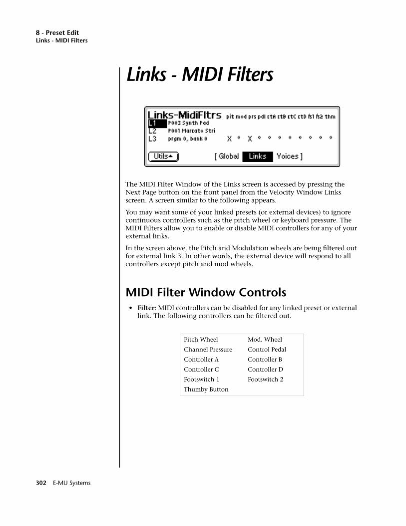
8 - Preset EditLinks - MIDI Filters
Links - MIDI Filters
The MIDI Filter Window of the Links screen is accessed by pressing the Next Page button on the front panel from the Velocity Window Links screen. A screen similar to the following appears.
You may want some of your linked presets (or external devices) to ignore continuous controllers such as the pitch wheel or keyboard pressure. The MIDI Filters allow you to enable or disable MIDI controllers for any of your external links.
In the screen above, the Pitch and Modulation wheels are being filtered out for external link 3. In other words, the external device will respond to all controllers except pitch and mod wheels.
MIDI Filter Window Controls• Filter: MIDI controllers can be disabled for any linked preset or external
link. The following controllers can be filtered out.
Pitch Wheel Mod. Wheel
Channel Pressure Control Pedal
Controller A Controller B
Controller C Controller D
Footswitch 1 Footswitch 2
Thumby Button
302 E-MU Systems
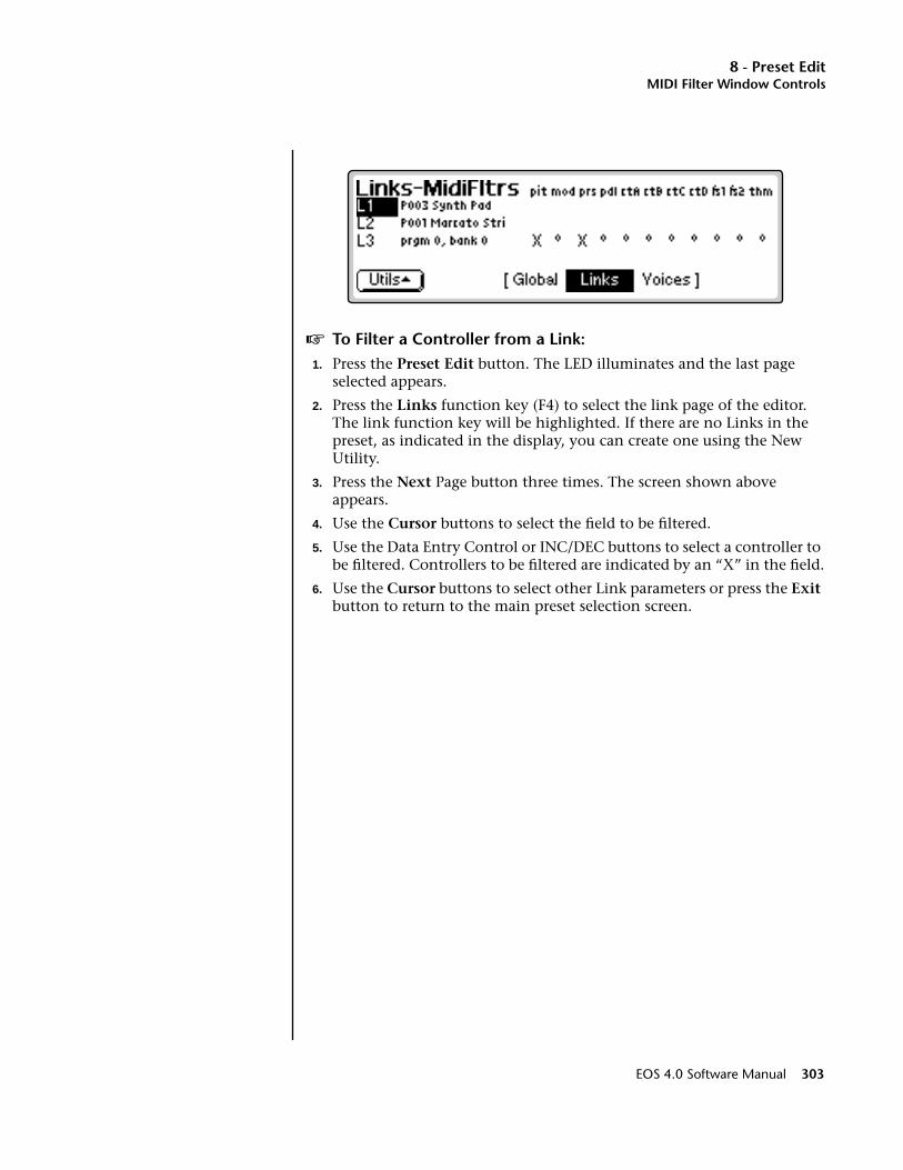
8 - Preset EditMIDI Filter Window Controls
v To Filter a Controller from a Link:1. Press the Preset Edit button. The LED illuminates and the last page
selected appears.
2. Press the Links function key (F4) to select the link page of the editor. The link function key will be highlighted. If there are no Links in the preset, as indicated in the display, you can create one using the New Utility.
3. Press the Next Page button three times. The screen shown above appears.
4. Use the Cursor buttons to select the field to be filtered.
5. Use the Data Entry Control or INC/DEC buttons to select a controller to be filtered. Controllers to be filtered are indicated by an “X” in the field.
6. Use the Cursor buttons to select other Link parameters or press the Exit button to return to the main preset selection screen.
EOS 4.0 Software Manual 303
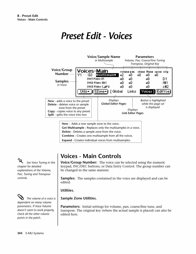
8 - Preset EditVoices - Main Controls
Preset Edit - Voices
Voices - Main ControlsOOOO See Voice Tuning in this chapter for detailed explanations of the Volume, Pan, Tuning and Transpose controls.
Voice/Group Number: The voice can be selected using the numeric keypad, INC/DEC buttons, or Data Entry Control. The group number can be changed in the same manner.
Samples: The samples contained in the voice are displayed and can be edited.
Utilities.
The volume of a voice is dependent on many volume parameters. If Voice Volume doesn’t seem to work properly, check all the other volume points in the patch.
Sample Zone Utilities.
Parameters: Initial settings for volume, pan, coarse/fine tune, and transpose. The original key (where the actual sample is placed) can also be edited here.
Voice/GroupNumber
Samplesin Voice
ParametersVolume, Pan, Coarse/Fine Tuning
Transpose, Original Key
DisplaysGlobal Editor Pages
New - adds a voice to the presetDelete - deletes voice or sample
zone from the presetCopy - copies voice to any presetSplit - splits the voice into two
DisplaysLink Editor Pages
Button is highlightedwhile this page set
is displayed.
New - Adds a new sample zone to the voice.Get Multisample - Replaces only the multisamples in a voice.Delete - Deletes a sample zone from the voice.Combine - Creates one multisample from all the voices.
Expand - Creates individual voices from multisamples.
Voice/Sample Nameor Multisample
304 E-MU Systems
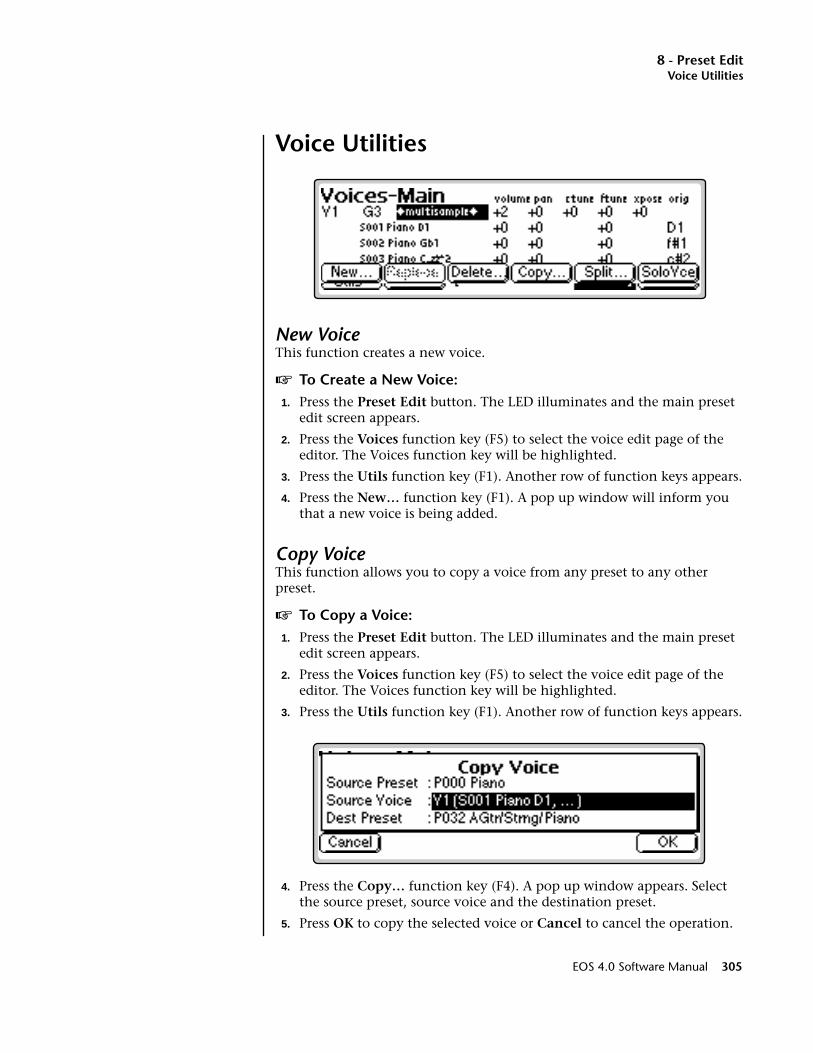
8 - Preset EditVoice Utilities
Voice Utilities
New VoiceThis function creates a new voice.
v To Create a New Voice:1. Press the Preset Edit button. The LED illuminates and the main preset
edit screen appears.
2. Press the Voices function key (F5) to select the voice edit page of the editor. The Voices function key will be highlighted.
3. Press the Utils function key (F1). Another row of function keys appears.
4. Press the New… function key (F1). A pop up window will inform you that a new voice is being added.
Copy VoiceThis function allows you to copy a voice from any preset to any other preset.
v To Copy a Voice:1. Press the Preset Edit button. The LED illuminates and the main preset
edit screen appears.
2. Press the Voices function key (F5) to select the voice edit page of the editor. The Voices function key will be highlighted.
3. Press the Utils function key (F1). Another row of function keys appears.
4. Press the Copy… function key (F4). A pop up window appears. Select the source preset, source voice and the destination preset.
5. Press OK to copy the selected voice or Cancel to cancel the operation.
EOS 4.0 Software Manual 305
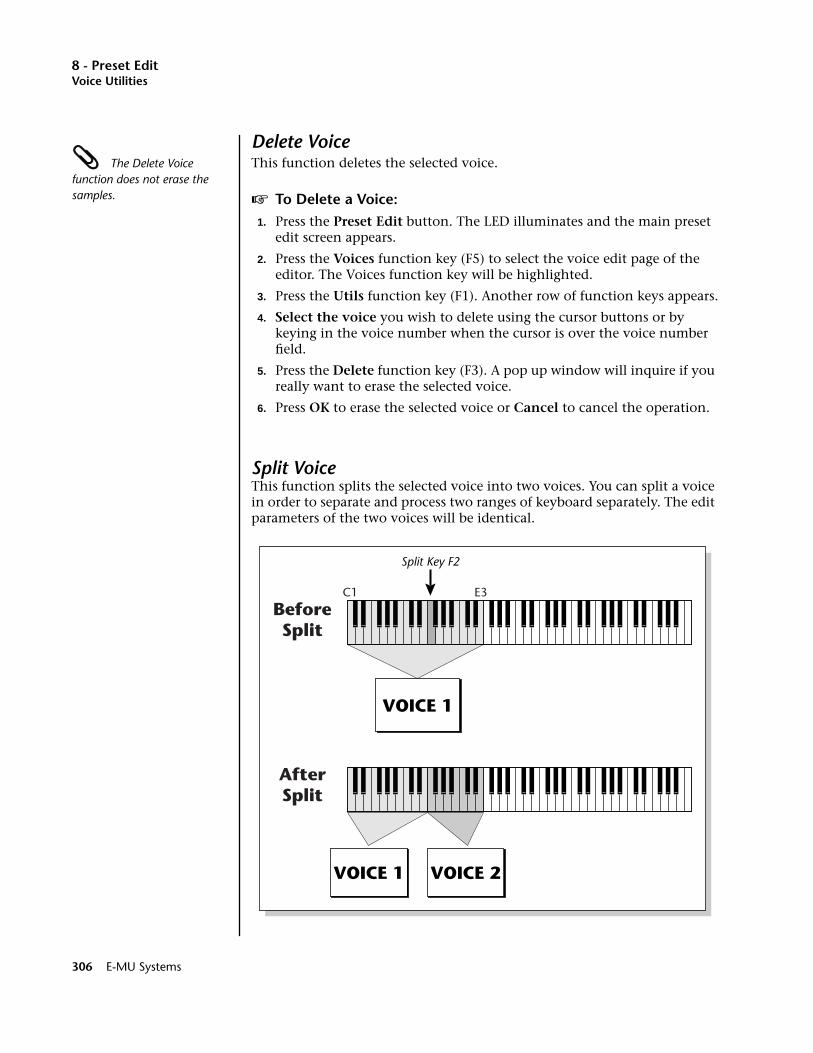
8 - Preset EditVoice Utilities
Delete Voice The Delete Voice function does not erase the samples.
This function deletes the selected voice.
v To Delete a Voice:1. Press the Preset Edit button. The LED illuminates and the main preset
edit screen appears.
2. Press the Voices function key (F5) to select the voice edit page of the editor. The Voices function key will be highlighted.
3. Press the Utils function key (F1). Another row of function keys appears.
4. Select the voice you wish to delete using the cursor buttons or by keying in the voice number when the cursor is over the voice number field.
5. Press the Delete function key (F3). A pop up window will inquire if you really want to erase the selected voice.
6. Press OK to erase the selected voice or Cancel to cancel the operation.
Split VoiceThis function splits the selected voice into two voices. You can split a voice in order to separate and process two ranges of keyboard separately. The edit parameters of the two voices will be identical.
Split Key F2
VOICE 1
C1 E3
VOICE 1 VOICE 2
BeforeSplit
AfterSplit
306 E-MU Systems
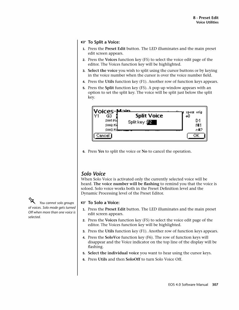
8 - Preset EditVoice Utilities
v To Split a Voice:1. Press the Preset Edit button. The LED illuminates and the main preset
edit screen appears.
2. Press the Voices function key (F5) to select the voice edit page of the editor. The Voices function key will be highlighted.
3. Select the voice you wish to split using the cursor buttons or by keying in the voice number when the cursor is over the voice number field.
4. Press the Utils function key (F1). Another row of function keys appears.
5. Press the Split function key (F5). A pop up window appears with an option to set the split key. The voice will be split just below the split key.
6. Press Yes to split the voice or No to cancel the operation.
Solo VoiceWhen Solo Voice is activated only the currently selected voice will be heard. The voice number will be flashing to remind you that the voice is soloed. Solo voice works both in the Preset Definition level and the Dynamic Processing level of the Preset Editor.
OOOO You cannot solo groups of voices. Solo mode gets turned Off when more than one voice is selected.
v To Solo a Voice:1. Press the Preset Edit button. The LED illuminates and the main preset
edit screen appears.
2. Press the Voices function key (F5) to select the voice edit page of the editor. The Voices function key will be highlighted.
3. Press the Utils function key (F1). Another row of function keys appears.
4. Press the SoloVce function key (F6). The row of function keys will disappear and the Voice indicator on the top line of the display will be flashing.
5. Select the individual voice you want to hear using the cursor keys.
6. Press Utils and then SoloOff to turn Solo Voice Off.
EOS 4.0 Software Manual 307
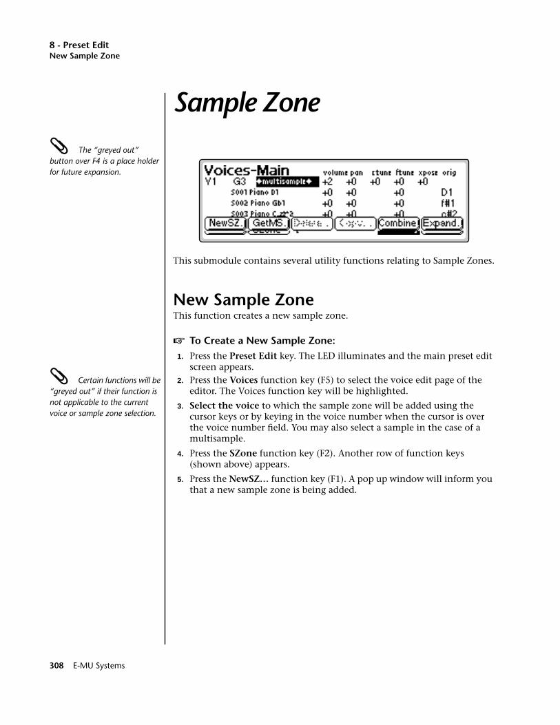
8 - Preset EditNew Sample Zone
Sample Zone The “greyed out” button over F4 is a place holder for future expansion.
This submodule contains several utility functions relating to Sample Zones.
New Sample ZoneThis function creates a new sample zone.
v To Create a New Sample Zone:1. Press the Preset Edit key. The LED illuminates and the main preset edit
screen appears. Certain functions will be “greyed out” if their function is not applicable to the current voice or sample zone selection.
2. Press the Voices function key (F5) to select the voice edit page of the editor. The Voices function key will be highlighted.
3. Select the voice to which the sample zone will be added using the cursor keys or by keying in the voice number when the cursor is over the voice number field. You may also select a sample in the case of a multisample.
4. Press the SZone function key (F2). Another row of function keys (shown above) appears.
5. Press the NewSZ… function key (F1). A pop up window will inform you that a new sample zone is being added.
308 E-MU Systems
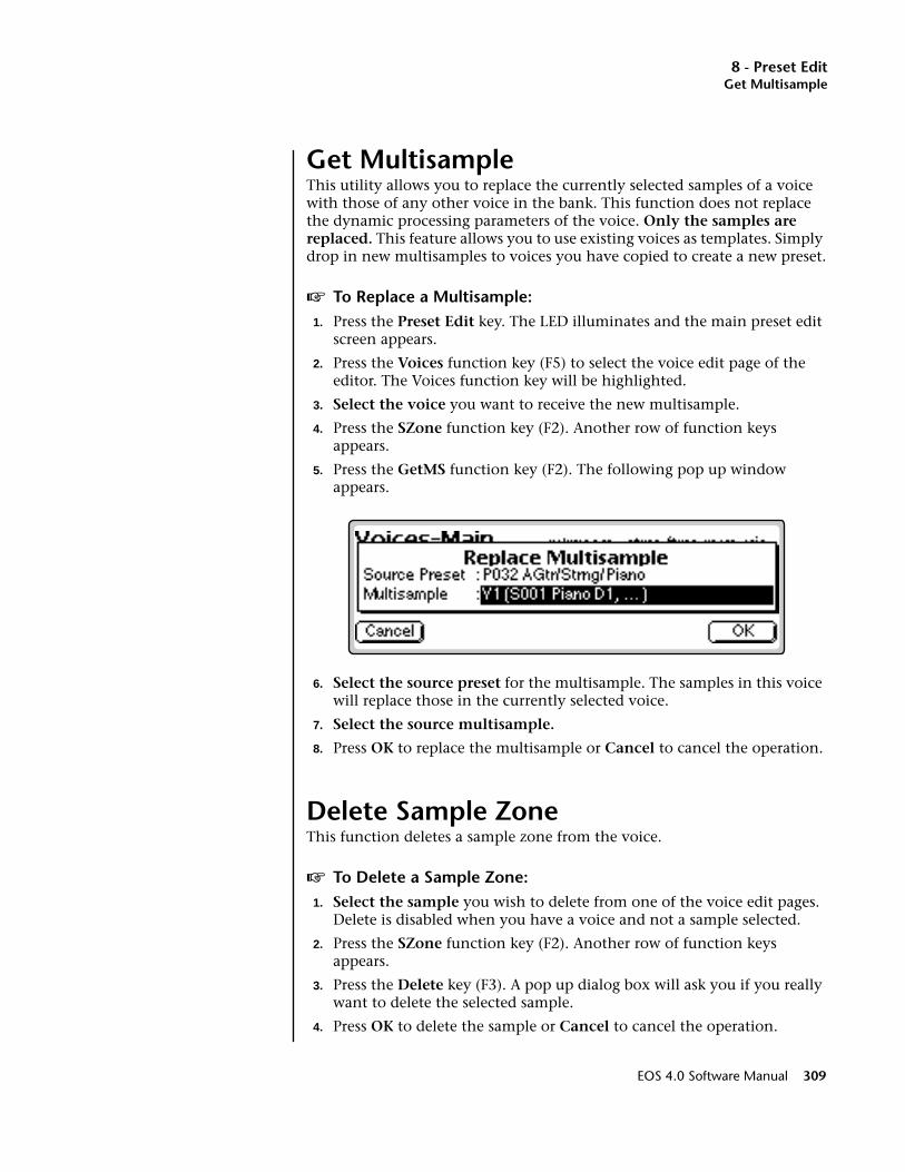
8 - Preset EditGet Multisample
Get MultisampleThis utility allows you to replace the currently selected samples of a voice with those of any other voice in the bank. This function does not replace the dynamic processing parameters of the voice. Only the samples are replaced. This feature allows you to use existing voices as templates. Simply drop in new multisamples to voices you have copied to create a new preset.
v To Replace a Multisample:1. Press the Preset Edit key. The LED illuminates and the main preset edit
screen appears.
2. Press the Voices function key (F5) to select the voice edit page of the editor. The Voices function key will be highlighted.
3. Select the voice you want to receive the new multisample.
4. Press the SZone function key (F2). Another row of function keys appears.
5. Press the GetMS function key (F2). The following pop up window appears.
6. Select the source preset for the multisample. The samples in this voice will replace those in the currently selected voice.
7. Select the source multisample.
8. Press OK to replace the multisample or Cancel to cancel the operation.
Delete Sample ZoneThis function deletes a sample zone from the voice.
v To Delete a Sample Zone:1. Select the sample you wish to delete from one of the voice edit pages.
Delete is disabled when you have a voice and not a sample selected.
2. Press the SZone function key (F2). Another row of function keys appears.
3. Press the Delete key (F3). A pop up dialog box will ask you if you really want to delete the selected sample.
4. Press OK to delete the sample or Cancel to cancel the operation.
EOS 4.0 Software Manual 309
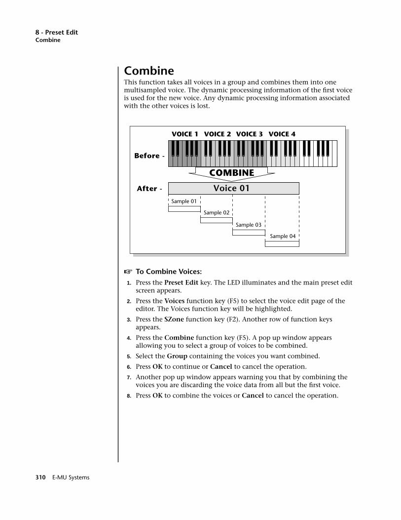
8 - Preset EditCombine
CombineThis function takes all voices in a group and combines them into one multisampled voice. The dynamic processing information of the first voice is used for the new voice. Any dynamic processing information associated with the other voices is lost.
v To Combine Voices:1. Press the Preset Edit key. The LED illuminates and the main preset edit
screen appears.
2. Press the Voices function key (F5) to select the voice edit page of the editor. The Voices function key will be highlighted.
3. Press the SZone function key (F2). Another row of function keys appears.
4. Press the Combine function key (F5). A pop up window appears allowing you to select a group of voices to be combined.
5. Select the Group containing the voices you want combined.
6. Press OK to continue or Cancel to cancel the operation.
7. Another pop up window appears warning you that by combining the voices you are discarding the voice data from all but the first voice.
8. Press OK to combine the voices or Cancel to cancel the operation.
VOICE 1 VOICE 2 VOICE 3 VOICE 4
Sample 01
Sample 02
Sample 03
Sample 04
Voice 01
COMBINE
Before -
After -
310 E-MU Systems

8 - Preset EditExpand...
Expand...This function takes apart the multisampled voices in a bank and makes an individual voice for each sample. The dynamic processing information of the “parent” voice is duplicated for each newly created voice.
v To Expand Multisampled Voices:1. Press the Preset Edit key. The LED illuminates and the main preset edit
screen appears.
2. Press the Voices function key (F5) to select the voice edit page of the editor. The Voices function key will be highlighted.
3. Press the SZone function key (F2). Another row of function keys appears.
4. Press the Expand.. function key (F6). A pop up window appears allowing you to select a group of voices to be expanded.
5. Select the group containing the voices you want expanded.
6. Press OK to expand the voices or Cancel to cancel the operation.
VOICE 1 VOICE 2 VOICE 3 VOICE 4
Sample 01
Sample 02
Sample 03
Sample 04
Voice 01EXPAND
Before -
After -
EOS 4.0 Software Manual 311
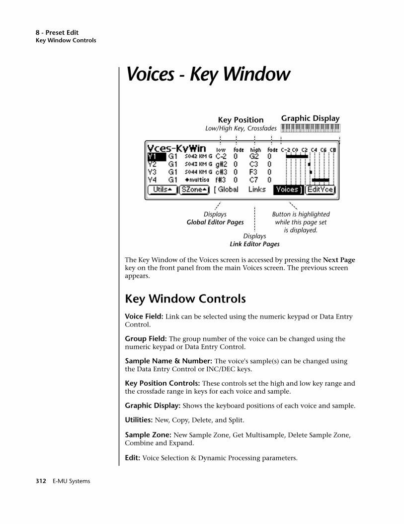
8 - Preset EditKey Window Controls
Voices - Key Window
The Key Window of the Voices screen is accessed by pressing the Next Page key on the front panel from the main Voices screen. The previous screen appears.
Key Window ControlsVoice Field: Link can be selected using the numeric keypad or Data Entry Control.
Group Field: The group number of the voice can be changed using the numeric keypad or Data Entry Control.
Sample Name & Number: The voice's sample(s) can be changed using the Data Entry Control or INC/DEC keys.
Key Position Controls: These controls set the high and low key range and the crossfade range in keys for each voice and sample.
Graphic Display: Shows the keyboard positions of each voice and sample.
Utilities: New, Copy, Delete, and Split.
Sample Zone: New Sample Zone, Get Multisample, Delete Sample Zone, Combine and Expand.
Edit: Voice Selection & Dynamic Processing parameters.
Key PositionLow/High Key, Crossfades
Graphic Display
DisplaysGlobal Editor Pages
DisplaysLink Editor Pages
Button is highlightedwhile this page set
is displayed.
312 E-MU Systems
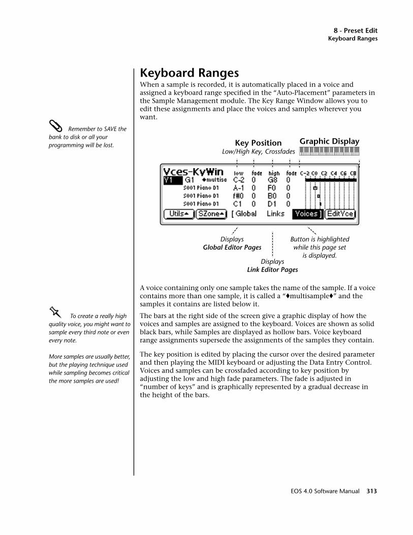
8 - Preset EditKeyboard Ranges
Keyboard RangesWhen a sample is recorded, it is automatically placed in a voice and assigned a keyboard range specified in the “Auto-Placement” parameters in the Sample Management module. The Key Range Window allows you to edit these assignments and place the voices and samples wherever you want.
Remember to SAVE the bank to disk or all your programming will be lost.
A voice containing only one sample takes the name of the sample. If a voice contains more than one sample, it is called a “♦multisample♦” and the samples it contains are listed below it.
OOOO To create a really high quality voice, you might want to sample every third note or even every note.
More samples are usually better, but the playing technique used while sampling becomes critical the more samples are used!
The bars at the right side of the screen give a graphic display of how the voices and samples are assigned to the keyboard. Voices are shown as solid black bars, while Samples are displayed as hollow bars. Voice keyboard range assignments supersede the assignments of the samples they contain.
The key position is edited by placing the cursor over the desired parameter and then playing the MIDI keyboard or adjusting the Data Entry Control. Voices and samples can be crossfaded according to key position by adjusting the low and high fade parameters. The fade is adjusted in “number of keys” and is graphically represented by a gradual decrease in the height of the bars.
Key PositionLow/High Key, Crossfades
Graphic Display
DisplaysGlobal Editor Pages
DisplaysLink Editor Pages
Button is highlightedwhile this page set
is displayed.
EOS 4.0 Software Manual 313

8 - Preset EditKeyboard Ranges
v To Switch Voices According to PositionAssigning voices (samples or multisamples) adjacent to each other is the simplest and most common application of the Key Window. This is also the way samples are “Auto-Placed” in the Sample Manage module. The voices in the screen below are each assigned a one octave range.
Another way of visualizing this assignment is shown below.OOOO Samples can be arranged in a voice in exactly the same way that voices are arranged on the keyboard. They can be arranged side by side on the keyboard to minimize the negative effects of pitch shifting or stacked on top of each other to create huge layered sounds, all within a single voice.
v To Layer Voices and SamplesThe ranges of two or more voices may overlap, and all voices assigned to a key will sound.
1. Press the Preset Edit key. The LED illuminates and the main preset edit screen appears.
2. Press the Voices function key (F5) to select the voice edit pages of the editor. The Voices function key will be highlighted.
3. Press the Next Page key. The Voices - Key Window appears.
4. Edit the High and Low keys of the voice ranges so they overlap as shown in the screen below. Both voices will now sound when their key range is played.
VOICE 1 VOICE 2 VOICE 3 VOICE 4
314 E-MU Systems
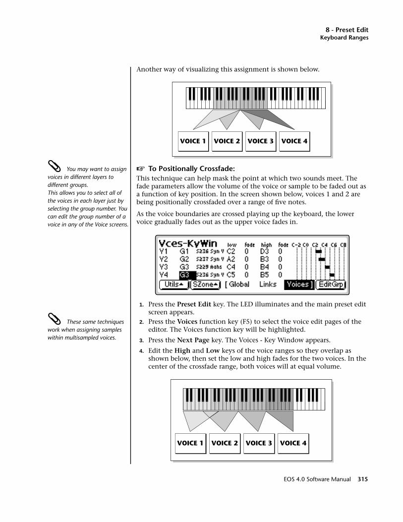
8 - Preset EditKeyboard Ranges
Another way of visualizing this assignment is shown below.
You may want to assign voices in different layers to different groups. This allows you to select all of the voices in each layer just by selecting the group number. You can edit the group number of a voice in any of the Voice screens.
v To Positionally Crossfade:This technique can help mask the point at which two sounds meet. The fade parameters allow the volume of the voice or sample to be faded out as a function of key position. In the screen shown below, voices 1 and 2 are being positionally crossfaded over a range of five notes.
As the voice boundaries are crossed playing up the keyboard, the lower voice gradually fades out as the upper voice fades in.
1. Press the Preset Edit key. The LED illuminates and the main preset edit screen appears.
These same techniques work when assigning samples within multisampled voices.
2. Press the Voices function key (F5) to select the voice edit pages of the editor. The Voices function key will be highlighted.
3. Press the Next Page key. The Voices - Key Window appears.
4. Edit the High and Low keys of the voice ranges so they overlap as shown below, then set the low and high fades for the two voices. In the center of the crossfade range, both voices will at equal volume.
VOICE 1 VOICE 2 VOICE 3 VOICE 4
VOICE 1 VOICE 2 VOICE 3 VOICE 4
EOS 4.0 Software Manual 315
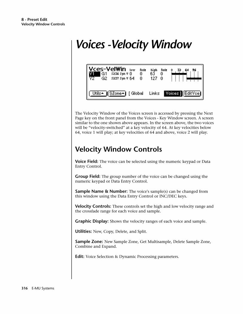
8 - Preset EditVelocity Window Controls
Voices -Velocity Window
The Velocity Window of the Voices screen is accessed by pressing the Next Page key on the front panel from the Voices - Key Window screen. A screen similar to the one shown above appears. In the screen above, the two voices will be “velocity-switched” at a key velocity of 64. At key velocities below 64, voice 1 will play; at key velocities of 64 and above, voice 2 will play.
Velocity Window Controls
Voice Field: The voice can be selected using the numeric keypad or Data Entry Control.
Group Field: The group number of the voice can be changed using the numeric keypad or Data Entry Control.
Sample Name & Number: The voice's sample(s) can be changed from this window using the Data Entry Control or INC/DEC keys.
Velocity Controls: These controls set the high and low velocity range and the crossfade range for each voice and sample.
Graphic Display: Shows the velocity ranges of each voice and sample.
Utilities: New, Copy, Delete, and Split.
Sample Zone: New Sample Zone, Get Multisample, Delete Sample Zone, Combine and Expand.
Edit: Voice Selection & Dynamic Processing parameters.
316 E-MU Systems
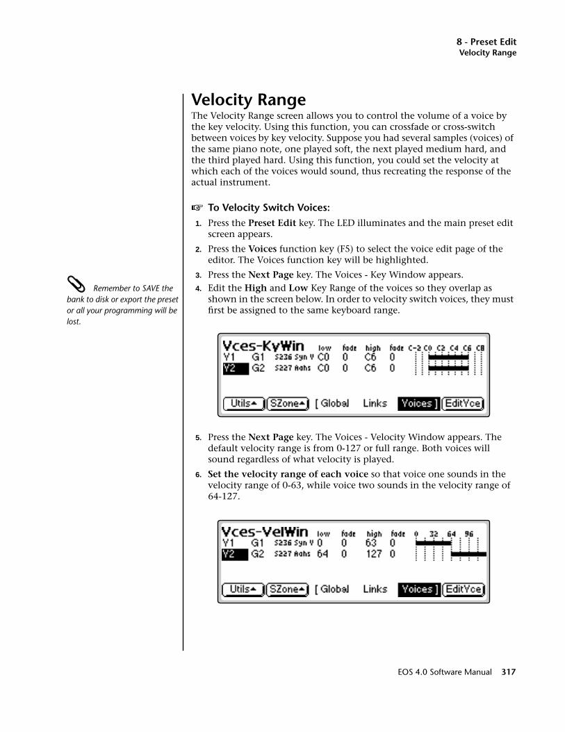
8 - Preset EditVelocity Range
Velocity RangeThe Velocity Range screen allows you to control the volume of a voice by the key velocity. Using this function, you can crossfade or cross-switch between voices by key velocity. Suppose you had several samples (voices) of the same piano note, one played soft, the next played medium hard, and the third played hard. Using this function, you could set the velocity at which each of the voices would sound, thus recreating the response of the actual instrument.
v To Velocity Switch Voices:1. Press the Preset Edit key. The LED illuminates and the main preset edit
screen appears.
2. Press the Voices function key (F5) to select the voice edit page of the editor. The Voices function key will be highlighted.
3. Press the Next Page key. The Voices - Key Window appears. Remember to SAVE the bank to disk or export the preset or all your programming will be lost.
4. Edit the High and Low Key Range of the voices so they overlap as shown in the screen below. In order to velocity switch voices, they must first be assigned to the same keyboard range.
5. Press the Next Page key. The Voices - Velocity Window appears. The default velocity range is from 0-127 or full range. Both voices will sound regardless of what velocity is played.
6. Set the velocity range of each voice so that voice one sounds in the velocity range of 0-63, while voice two sounds in the velocity range of 64-127.
EOS 4.0 Software Manual 317
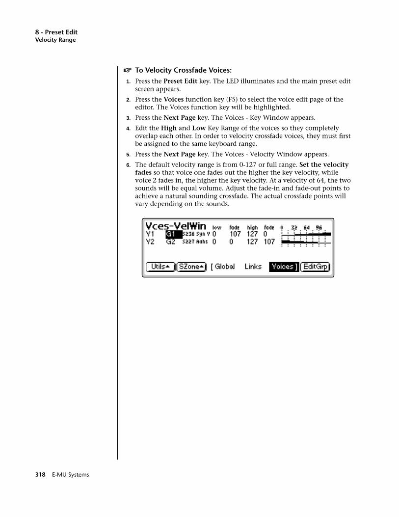
8 - Preset EditVelocity Range
v To Velocity Crossfade Voices:1. Press the Preset Edit key. The LED illuminates and the main preset edit
screen appears.
2. Press the Voices function key (F5) to select the voice edit page of the editor. The Voices function key will be highlighted.
3. Press the Next Page key. The Voices - Key Window appears.
4. Edit the High and Low Key Range of the voices so they completely overlap each other. In order to velocity crossfade voices, they must first be assigned to the same keyboard range.
5. Press the Next Page key. The Voices - Velocity Window appears.
6. The default velocity range is from 0-127 or full range. Set the velocity fades so that voice one fades out the higher the key velocity, while voice 2 fades in, the higher the key velocity. At a velocity of 64, the two sounds will be equal volume. Adjust the fade-in and fade-out points to achieve a natural sounding crossfade. The actual crossfade points will vary depending on the sounds.
318 E-MU Systems
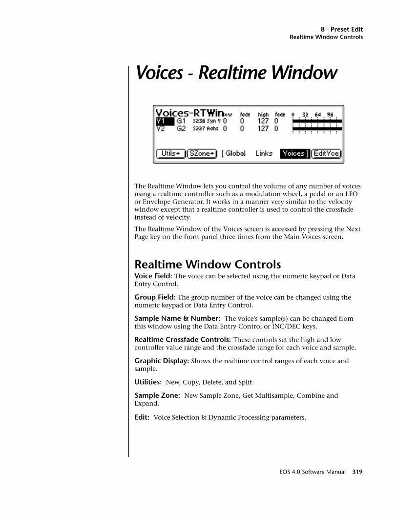
8 - Preset EditRealtime Window Controls
Voices - Realtime Window
The Realtime Window lets you control the volume of any number of voices using a realtime controller such as a modulation wheel, a pedal or an LFO or Envelope Generator. It works in a manner very similar to the velocity window except that a realtime controller is used to control the crossfade instead of velocity.
The Realtime Window of the Voices screen is accessed by pressing the Next Page key on the front panel three times from the Main Voices screen.
Realtime Window ControlsVoice Field: The voice can be selected using the numeric keypad or Data Entry Control.
Group Field: The group number of the voice can be changed using the numeric keypad or Data Entry Control.
Sample Name & Number: The voice's sample(s) can be changed from this window using the Data Entry Control or INC/DEC keys.
Realtime Crossfade Controls: These controls set the high and low controller value range and the crossfade range for each voice and sample.
Graphic Display: Shows the realtime control ranges of each voice and sample.
Utilities: New, Copy, Delete, and Split.
Sample Zone: New Sample Zone, Get Multisample, Combine and Expand.
Edit: Voice Selection & Dynamic Processing parameters.
EOS 4.0 Software Manual 319

8 - Preset EditRealtime Window Controls
v To Realtime Crossfade Voices:1. Press the Preset Edit key. The LED illuminates and the main preset edit
screen appears.
2. Press the Voices function key (F5) to select the voice edit page of the editor. The Voices function key will be highlighted.
3. Press the Next Page key. The Voices - Key Window appears.
4. Edit the High and Low Key Range of the voices so they completely overlap each other. In order to velocity crossfade voices, they must first be assigned to the same keyboard range.
5. Press the Next Page key twice. The Voices - Realtime Window appears.
6. Set the realtime range of each voice. The next screen shows the realtime ranges set so that voice one will begin fading in after the realtime controller reaches a value of 32. Voice two will begin fading out when the realtime control reaches 32 and fades completely out by a value of 80.
____ Realtime Crossfading is one of the more “advanced” applications of the machine. Make sure you understand how to select voices and assign cords before attempting to perform realtime crossfades.
7. So far so good, but this is a Realtime Range. We have to assign a realtime Controller to control the crossfade. Press EditVce to enter the Dynamic Processing level.
8. Press the Utils function key (F1).
9. Press the VSelect function key (F2) to bring up the voice selection screen.
10. Select all voices you wish to realtime crossfade. Press OK.
11. Press the Cords function key (F5). The patchcord assign screen appears.
12. Assign one of the realtime control sources such as the mod wheel or an LFO to AmpXfd. Turn up the Amount parameter to 100%. You should be able to hear the crossfade.
13. Adjust the crossfade ranges and the AmpXfd amount until the crossfade responds correctly.
In certain situations, such as setting up drum kits, you may want to randomly switch between several voices. Crossfade Random is a modulation source specifically designed to handle this situation. Unlike the other random sources, Crossfade Random generates one random number for all voices that are assigned to the same key.
320 E-MU Systems

8 - Preset EditRealtime Window Controls
v To Randomly Cross-Switch Between Voices:1. Press the Preset Edit key. The LED illuminates and the main preset edit
screen appears.
2. Press the Voices function key (F5) to select the voice edit page of the editor. The Voices function key will be highlighted.
3. Press the Next Page key. The Voices - Key Window appears.
4. Edit the High and Low Key Range of the voices so they completely overlap each other. In order to randomly crossfade voices, they must first be assigned to the same keyboard range.
5. Press the Next Page key twice. The Voices - Realtime Window appears.
6. Set the realtime range of each voice. The next screen shows the realtime ranges set so that voice 1 will sound whenever the random value is from 0 to 64. Voice 2 will sound whenever the random value is greater than 64.
v To Randomly Cross-Switch Between Voices:7. Now you have to assign a realtime Controller to control the cross-
switch. Press EditVce to enter the Dynamic Processing level.
8. Press the Utils function key (F1) and then the VSelect function key (F1) to bring up the voice selection screen.
9. Select all voices you wish to realtime crossfade.
10. Press OK.
11. Press the Cords function key (F5). The patchcord assign screen appears.
12. Assign XfdRnd to AmpXfd.
13. Set the Amount to 100%.
EOS 4.0 Software Manual 321
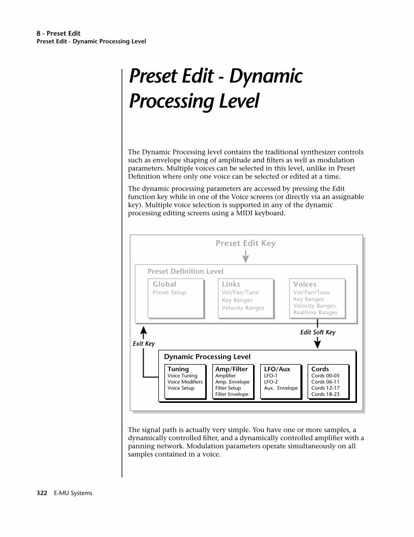
8 - Preset EditPreset Edit - Dynamic Processing Level
Preset Edit - Dynamic Processing Level
The Dynamic Processing level contains the traditional synthesizer controls such as envelope shaping of amplitude and filters as well as modulation parameters. Multiple voices can be selected in this level, unlike in Preset Definition where only one voice can be selected or edited at a time.
The dynamic processing parameters are accessed by pressing the Edit function key while in one of the Voice screens (or directly via an assignable key). Multiple voice selection is supported in any of the dynamic processing editing screens using a MIDI keyboard.
The signal path is actually very simple. You have one or more samples, a dynamically controlled filter, and a dynamically controlled amplifier with a panning network. Modulation parameters operate simultaneously on all samples contained in a voice.
Preset Edit Key
GlobalPreset Setup
LinksVol/Pan/TuneKey RangesVelocity Ranges
VoicesVol/Pan/TuneKey RangesVelocity RangesRealtime Ranges
TuningVoice TuningVoice ModifiersVoice Setup
Amp/FilterAmplifierAmp. EnvelopeFilter SetupFilter Envelope
LFO/AuxLFO-1LFO-2Aux. Envelope
CordsCords 00-05Cords 06-11Cords 12-17Cords 18-23
Dynamic Processing Level
Preset Definition Level
Exit Key
Edit Soft Key
322 E-MU Systems
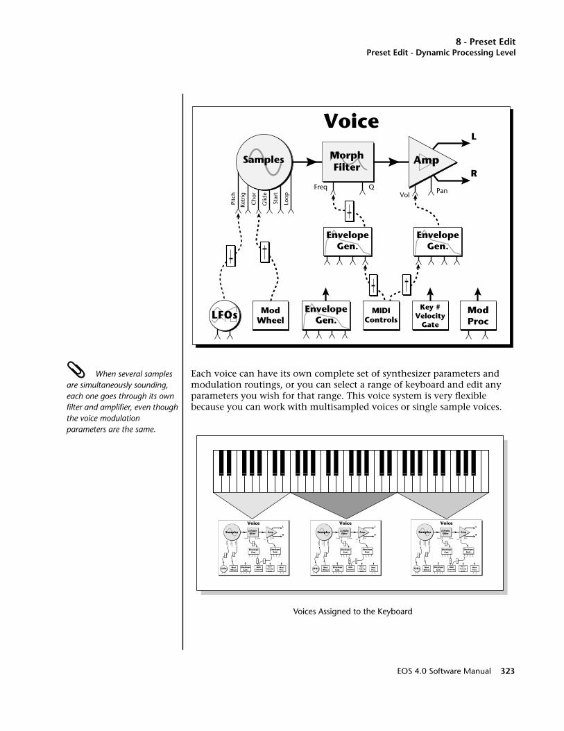
8 - Preset EditPreset Edit - Dynamic Processing Level
When several samples are simultaneously sounding, each one goes through its own filter and amplifier, even though the voice modulation parameters are the same.
Each voice can have its own complete set of synthesizer parameters and modulation routings, or you can select a range of keyboard and edit any parameters you wish for that range. This voice system is very flexible because you can work with multisampled voices or single sample voices.
Voices Assigned to the Keyboard
Samples Amp
L
R
LFOs EnvelopeGen.
EnvelopeGen.
EnvelopeGen.
ModProc
ModWheel
MIDIControls
Key #Velocity
Gate
Retr
ig
Pitc
h
Loop
Freq QVol
Pan
Cho
r
Glid
e
Star
t
Voice
MorphFilter
Samples Amp
L
R
EnvelopeGen.
Cutoff GainVol
Pitc
h
Glid
e
Cho
rus
Pan
Voice
Z-PlaneFilter
EnvelopeGen.
EnvelopeGen.LFOs Mod
WheelMIDI
ControlsMod.Proc.
Key #Velocity
Gate
Samples Amp
L
R
EnvelopeGen.
Cutoff GainVol
Pitc
h
Glid
e
Cho
rus
Pan
Voice
Z-PlaneFilter
EnvelopeGen.
EnvelopeGen.LFOs Mod
WheelMIDI
ControlsMod.Proc.
Key #Velocity
Gate
Samples Amp
L
R
EnvelopeGen.
Cutoff GainVol
Pitc
h
Glid
e
Cho
rus
Pan
Voice
Z-PlaneFilter
EnvelopeGen.
EnvelopeGen.LFOs Mod
WheelMIDI
ControlsMod.Proc.
Key #Velocity
Gate
EOS 4.0 Software Manual 323
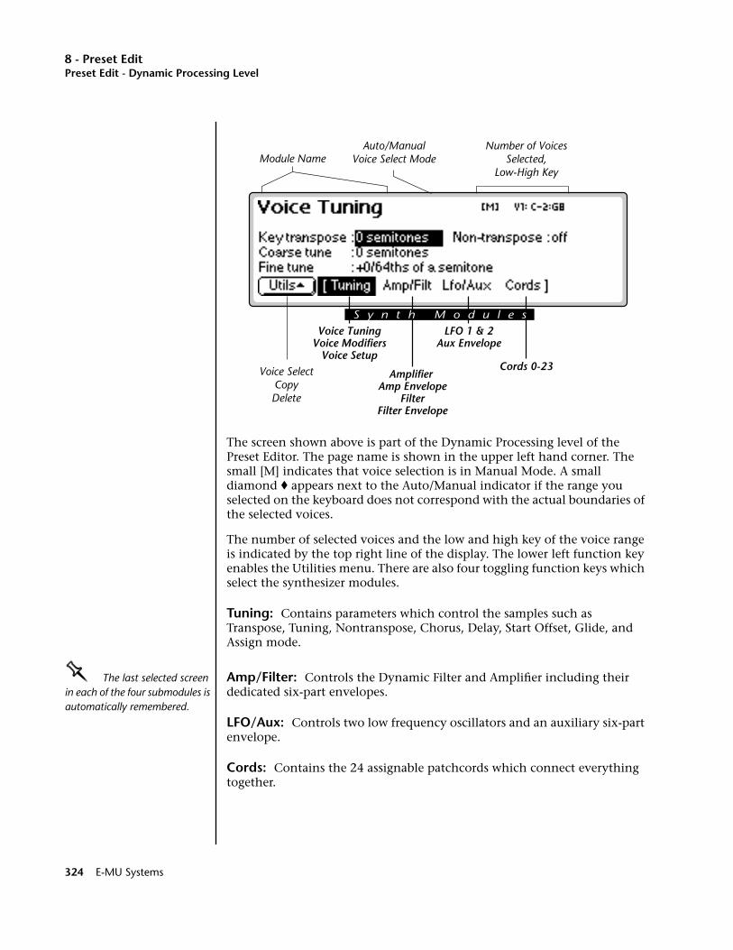
8 - Preset EditPreset Edit - Dynamic Processing Level
The screen shown above is part of the Dynamic Processing level of the Preset Editor. The page name is shown in the upper left hand corner. The small [M] indicates that voice selection is in Manual Mode. A small diamond ♦ appears next to the Auto/Manual indicator if the range you selected on the keyboard does not correspond with the actual boundaries of the selected voices.
The number of selected voices and the low and high key of the voice range is indicated by the top right line of the display. The lower left function key enables the Utilities menu. There are also four toggling function keys which select the synthesizer modules.
Tuning: Contains parameters which control the samples such as Transpose, Tuning, Nontranspose, Chorus, Delay, Start Offset, Glide, and Assign mode.
OOOO The last selected screen in each of the four submodules is automatically remembered.
Amp/Filter: Controls the Dynamic Filter and Amplifier including their dedicated six-part envelopes.
LFO/Aux: Controls two low frequency oscillators and an auxiliary six-part envelope.
Cords: Contains the 24 assignable patchcords which connect everything together.
Voice SelectCopyDelete
Cords 0-23
Voice TuningVoice Modifiers
Voice Setup
LFO 1 & 2Aux Envelope
Amplifier Amp Envelope
FilterFilter Envelope
Auto/ManualVoice Select ModeModule Name
Number of VoicesSelected,
Low-High Key
S y n t h M o d u l e s
324 E-MU Systems
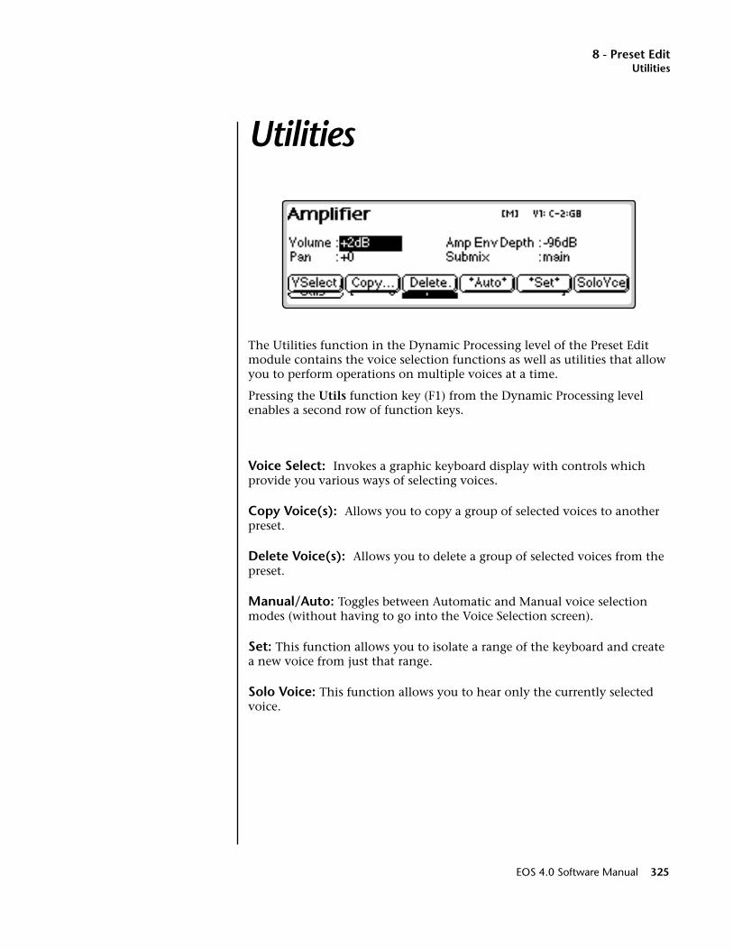
8 - Preset EditUtilities
Utilities
The Utilities function in the Dynamic Processing level of the Preset Edit module contains the voice selection functions as well as utilities that allow you to perform operations on multiple voices at a time.
Pressing the Utils function key (F1) from the Dynamic Processing level enables a second row of function keys.
Voice Select: Invokes a graphic keyboard display with controls which provide you various ways of selecting voices.
Copy Voice(s): Allows you to copy a group of selected voices to another preset.
Delete Voice(s): Allows you to delete a group of selected voices from the preset.
Manual/Auto: Toggles between Automatic and Manual voice selection modes (without having to go into the Voice Selection screen).
Set: This function allows you to isolate a range of the keyboard and create a new voice from just that range.
Solo Voice: This function allows you to hear only the currently selected voice.
EOS 4.0 Software Manual 325
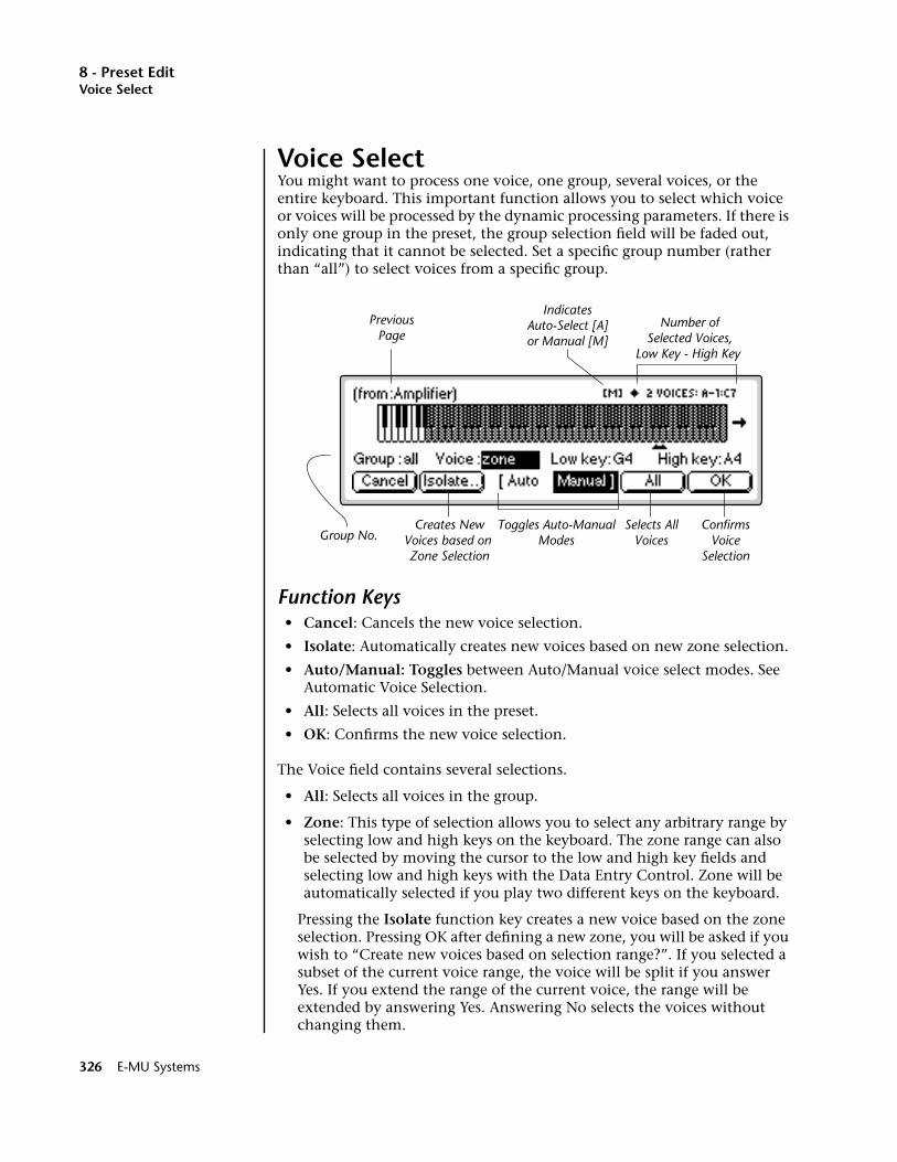
8 - Preset EditVoice Select
Voice SelectYou might want to process one voice, one group, several voices, or the entire keyboard. This important function allows you to select which voice or voices will be processed by the dynamic processing parameters. If there is only one group in the preset, the group selection field will be faded out, indicating that it cannot be selected. Set a specific group number (rather than “all”) to select voices from a specific group.
Function Keys• Cancel: Cancels the new voice selection.
• Isolate: Automatically creates new voices based on new zone selection.
• Auto/Manual: Toggles between Auto/Manual voice select modes. See Automatic Voice Selection.
• All: Selects all voices in the preset.
• OK: Confirms the new voice selection.
The Voice field contains several selections.
• All: Selects all voices in the group.
• Zone: This type of selection allows you to select any arbitrary range by selecting low and high keys on the keyboard. The zone range can also be selected by moving the cursor to the low and high key fields and selecting low and high keys with the Data Entry Control. Zone will be automatically selected if you play two different keys on the keyboard.
Pressing the Isolate function key creates a new voice based on the zone selection. Pressing OK after defining a new zone, you will be asked if you wish to “Create new voices based on selection range?”. If you selected a subset of the current voice range, the voice will be split if you answer Yes. If you extend the range of the current voice, the range will be extended by answering Yes. Answering No selects the voices without changing them.
IndicatesAuto-Select [A]or Manual [M]
Number ofSelected Voices,
Low Key - High Key
PreviousPage
Toggles Auto-ManualModes
Selects AllVoices
Creates NewVoices based on Zone Selection
ConfirmsVoice
Selection
Group No.
326 E-MU Systems
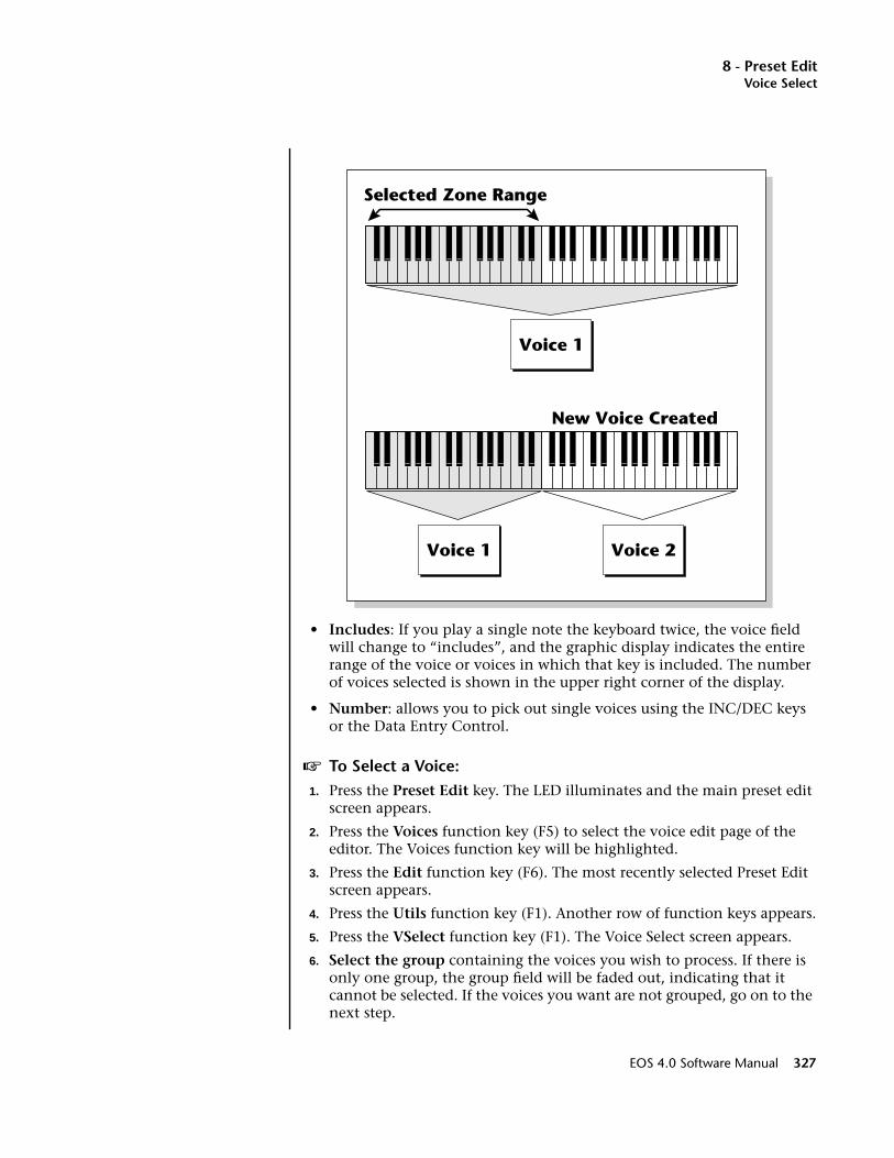
8 - Preset EditVoice Select
• Includes: If you play a single note the keyboard twice, the voice field will change to “includes”, and the graphic display indicates the entire range of the voice or voices in which that key is included. The number of voices selected is shown in the upper right corner of the display.
• Number: allows you to pick out single voices using the INC/DEC keys or the Data Entry Control.
v To Select a Voice:1. Press the Preset Edit key. The LED illuminates and the main preset edit
screen appears.
2. Press the Voices function key (F5) to select the voice edit page of the editor. The Voices function key will be highlighted.
3. Press the Edit function key (F6). The most recently selected Preset Edit screen appears.
4. Press the Utils function key (F1). Another row of function keys appears.
5. Press the VSelect function key (F1). The Voice Select screen appears.
6. Select the group containing the voices you wish to process. If there is only one group, the group field will be faded out, indicating that it cannot be selected. If the voices you want are not grouped, go on to the next step.
Voice 1
Selected Zone Range
Voice 1 Voice 2
New Voice Created
EOS 4.0 Software Manual 327
8 - Preset EditCopy Voice(s)
7. Select the voices you wish to process by playing a note on the keyboard or by selecting the voice number for the “Voice” field.
• Playing a single note on the keyboard changes the voice selector field to “includes” and the voice range you have selected will be darkened on the keyboard display. The upper right corner of the dis-play shows the number of voices you have selected.
• Playing two different notes on the keyboard changes the voice selector field to “zone”. The voice range you have selected will be shown by the range bar below the display. If you press OK a pop up window will ask you if you want to create a new voice from the selected range. Choosing Yes creates a new voice. Choosing No simply selects the included voices.
8. Press OK to confirm the selected voice(s) or Cancel to cancel the operation.
The Isolate Key:Use this key when you want to make a new voice from a section of another voice in order to separately process it.
v To Isolate a Key1. In the voice selection screen, set the Voice parameter to Zone.
2. Move the cursor and set the Low and High keys of the new voice range using the Data Entry Control, INC/DEC keys or the keyboard.
3. Press the Isolate function key (F2). A new voice will instantly be created.
4. Select the new voice and process it.
Copy Voice(s)In the Preset Definition level, only one voice can be selected and copied at a time. In this layer, the Dynamic Processing level, multiple voices can be selected. This copy function is different in that it allows multiple voices to be copied and pasted.
v To Copy Multiple Voices:1. Press the Preset Edit key. The LED illuminates and the main preset edit
screen appears.
2. Press the Voices function key (F5) to select the voice edit pages of the editor. The Voices function key will be highlighted.
3. Press the Edit function key (F6) to select the dynamic processing level of the editor.
328 E-MU Systems
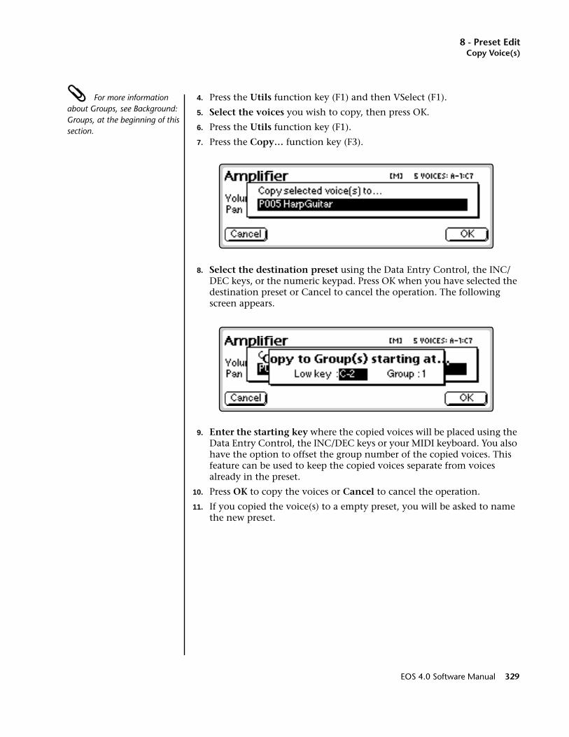
8 - Preset EditCopy Voice(s)
For more information about Groups, see Background: Groups, at the beginning of this section.
4. Press the Utils function key (F1) and then VSelect (F1).
5. Select the voices you wish to copy, then press OK.
6. Press the Utils function key (F1).
7. Press the Copy… function key (F3).
8. Select the destination preset using the Data Entry Control, the INC/DEC keys, or the numeric keypad. Press OK when you have selected the destination preset or Cancel to cancel the operation. The following screen appears.
9. Enter the starting key where the copied voices will be placed using the Data Entry Control, the INC/DEC keys or your MIDI keyboard. You also have the option to offset the group number of the copied voices. This feature can be used to keep the copied voices separate from voices already in the preset.
10. Press OK to copy the voices or Cancel to cancel the operation.
11. If you copied the voice(s) to a empty preset, you will be asked to name the new preset.
EOS 4.0 Software Manual 329

8 - Preset EditDelete Voice(s)
Copied voices can be placed in the destination preset starting at any key number and starting at any group number.
Delete Voice(s)Multiple voices can be deleted at a time using this function. The samples contained within the voices are not deleted.
v To Delete Multiple Voices:1. Press the Preset Edit key. The LED illuminates and the main preset edit
screen appears.
2. Press the Voices function key (F5) to select the voice edit page of the editor. The Voices function key will be highlighted.
3. Press the Edit function key (F6) to select the dynamic processing level of the editor.
4. Press the Utils function key (F1) and then VSelect (F1).
5. Select the voices you wish to delete, then press OK.
6. Press the Utils function key (F1). A pop up window appears asking you if you really do want to erase the selected voices.
7. Press OK to delete the selected voices or Cancel to cancel the operation.
Selected Voices
G1Group - G2 G3
G10 G11 G12
Co
py
StartingLow Key
CurrentPreset
DestinationPreset
StartingGroup = 10
330 E-MU Systems

8 - Preset EditAutomatic Voice Selection
Automatic Voice SelectionVoices within the currently selected group (or All) may also be selected directly from any voice edit screen without having to go back to the voice select screen.
v To Select a Voice using the Auto Select feature:1. From the Voice Selection screen (Preset Edit, Edit Voice, Utils, VSelect),
press Auto (F3).
2. Select a group number (if desired) from the voice selection screen. Auto Select will only select voices from the group you choose (group number or all).
3. Press OK to exit voice selection.
4. Voices will now be selected by playing the keyboard in any voice edit screen (Tuning, Amp/Filt, LFO/Aux, Cords).
5. Selecting a single note will select all voices assigned to that key.
6. Selecting a keyboard range by pressing two notes at once will select all voices within that range.
SetThis button performs the same function as the Isolate key in the Voice Selection screen. If the selected key range does not exactly match the voice ranges, you will be asked if you want to isolate new voices from the existing range. Pressing Yes creates a new voice or voices based on your selected range. Pressing No simply selects the included voices.
Solo VoiceWhen Solo Voice is activated only the currently selected voice will be heard. The voice number will be flashing to remind you that the voice is soloed. Solo voice works both in the Preset Definition level and the Dynamic Processing level of the Preset Editor.
See “Solo Voice” on page 307.
WARNING!Be careful when selecting a range of voices using Auto Select! When you play the keyboard to hear the results of your edit, you are changing the voice selection range. Be sure to re-key the voice selection range before resuming your editing.
EOS 4.0 Software Manual 331

8 - Preset EditVoice Tuning, Modifiers & Setup
Voice Tuning, Modifiers & Setup
The voice contains several tuning and setup parameters.
• Key Transpose
• Coarse Tuning
• Fine TuningOOOO Transpose, coarse tune, and fine tune can also be edited at the preset definition level in the Voices-Main screen.
• Non-Transpose Mode
• Chorus Parameters
• Delay
• Start Offset
• Glide Parameters
• Solo Modes
• Assignment Group
• Latch Mode
332 E-MU Systems
8 - Preset EditKey Transpose
Key TransposeThis function allows you to transpose the key of the selected voice(s) in semitone intervals by shifting the keyboard position relative to middle C. The transpose range is -24 to +24 semitones. You will normally use the transpose function to tune a voice to its keyboard location, or simply to transpose the voice.
v To Transpose a Voice:1. From the Dynamic Processing level of the Preset Editor, select the
voice(s) you wish to transpose using the voice selection screen.
2. Press the Tuning function key (F2).
3. Use the Previous and Next Page keys to locate the Voice Tuning screen shown on the previous page.
4. Select Key Transpose using the cursor keys.
5. Change the transpose parameter to the desired amount using the Data Entry Control or the INC/DEC keys.
6. Press the Exit key to return to the Preset Definition level of the Preset Editor or press any of the dynamic processing function keys to move to another module.
Coarse TuningOOOO Use Transpose when you want the voice's timbre to remain constant.
Use Coarse Tuning when you want to change the timbre of the voice.
This function allows you to change the tuning of the voice in semitone intervals. The coarse tuning range is -72 to +24 semitones. Unlike the transpose function, coarse tuning stretches the pitch of the individual samples assigned to a key and may change the timbre of a voice.
v To Coarse Tune a Voice:1. From the Dynamic Processing level of the Preset Editor, select the
voice(s) you wish to coarse tune using the voice selection screen, then press the Tuning function key (F2).
2. Use the Previous and Next Page keys to locate the Voice Tuning screen.
3. Select Coarse Tune using the cursor keys.
4. Change the Coarse Tuning parameter to the desired amount using the Data Entry Control or the INC/DEC keys.
OOOO Use the Coarse Tuning control to change the tuning of voices containing multiple drums.
5. Press the Exit key to return to the Preset Definition level of the Preset Editor or press any of the dynamic processing function keys to move to another module.
EOS 4.0 Software Manual 333
8 - Preset EditFine Tuning
Fine TuningThis function allows you to change the tuning of the voice in 1/64 semitone intervals (approx. 1.56 cents). The fine tuning range is ± 1 semitone. Fine tuning can be used to slightly detune a voice, creating a “fatter” sound when it is combined with another voice.
v To Fine Tune a Voice:1. From the Dynamic Processing level of the Preset Editor, select the
voice(s) you wish to fine tune using the voice selection screen, then press the Tuning function key (F2).
2. Use the Previous and Next Page keys to locate the Voice Tuning screen.
3. Select Fine Tuning using the cursor keys.
4. Adjust the Fine Tuning parameter to the desired amount using the Data Entry Control or the INC/DEC keys.
5. Press the Exit key to return to the Preset Definition level of the Preset Editor or press any of the dynamic processing function keys to move to another module.
Non-transpose ModeThis function turns keyboard transposition On or Off for the voice. With Nontranspose On, the keyboard will not control the pitch of the voice. This is a useful function for drones or “chiffs”, which you may not want to track the keyboard.
v To Set a Voice to Non-Transpose:1. From the Dynamic Processing level of the Preset Editor, select the
voice(s) you wish to put in non-transpose mode using the voice selection screen, then press the Tuning function key (F2).
2. Use the Previous and Next Page keys to locate the Voice Tuning screen.
3. Select Nontranspose using the cursor keys.
4. Turn Non-transpose On or Off using the Data Entry Control or the INC/DEC keys.
5. Press the Exit key to return to the Preset Definition level of the Preset Editor or press any of the dynamic processing function keys to move to another module.
334 E-MU Systems
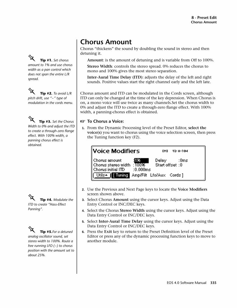
8 - Preset EditChorus Amount
Chorus AmountChorus “thickens” the sound by doubling the sound in stereo and then detuning it.
OOOO Tip #1. Set chorus amount to 1% and use chorus width as a pan control which does not span the entire L/R spread.
Amount: is the amount of detuning and is variable from Off to 100%.
Stereo Width: controls the stereo spread. 0% reduces the chorus to mono and 100% gives the most stereo separation.
Inter-Aural Time Delay (ITD): adjusts the delay of the left and right sounds. Positive values start the right channel early and the left late.
OOOO Tip #2. To avoid L/R pitch drift, use “~” type of modulation in the cords menu.
Chorus amount and ITD can be modulated in the Cords screen, although ITD can only be changed at the time of the key depression. When Chorus is on, a mono voice will use twice as many channels.Set the chorus width to 0% and adjust the ITD to create a through-zero flange effect. With 100% width, a panning-chorus effect is obtained.
OOOO Tip #3. Set the Chorus Width to 0% and adjust the ITD to create a through-zero flange effect. With 100% width, a panning chorus effect is obtained.
v To Chorus a Voice:1. From the Dynamic Processing level of the Preset Editor, select the
voice(s) you want to chorus using the voice selection screen, then press the Tuning function key (F2).
2. Use the Previous and Next Page keys to locate the Voice Modifiers screen shown above.
OOOO Tip #4. Modulate the ITD to create “Hass-Effect Panning”.
3. Select Chorus Amount using the cursor keys. Adjust using the Data Entry Control or INC/DEC keys.
4. Select the Chorus Stereo Width using the cursor keys. Adjust using the Data Entry Control or INC/DEC keys.
5. Select Inter-Aural Time Delay using the cursor keys. Adjust using the Data Entry Control or INC/DEC keys.
OOOO Tip #5.For a detuned analog oscillator sound, set stereo width to 100%. Route a free running LFO (~) to chorus position with the amount set to about 25%.
6. Press the Exit key to return to the Preset Definition level of the Preset Editor or press any of the dynamic processing function keys to move to another module.
EOS 4.0 Software Manual 335
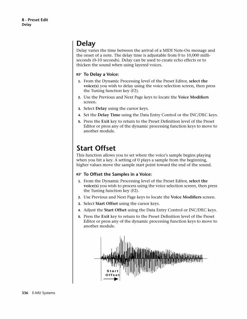
8 - Preset EditDelay
DelayDelay varies the time between the arrival of a MIDI Note-On message and the onset of a note. The delay time is adjustable from 0 to 10,000 milli-seconds (0-10 seconds). Delay can be used to create echo effects or to thicken the sound when using layered voices.
v To Delay a Voice:1. From the Dynamic Processing level of the Preset Editor, select the
voice(s) you wish to delay using the voice selection screen, then press the Tuning function key (F2).
2. Use the Previous and Next Page keys to locate the Voice Modifiers screen.
3. Select Delay using the cursor keys.
4. Set the Delay Time using the Data Entry Control or the INC/DEC keys.
5. Press the Exit key to return to the Preset Definition level of the Preset Editor or press any of the dynamic processing function keys to move to another module.
Start OffsetThis function allows you to set where the voice's sample begins playing when you hit a key. A setting of 0 plays a sample from the beginning, higher values move the sample start point toward the end of the sound.
v To Offset the Samples in a Voice:1. From the Dynamic Processing level of the Preset Editor, select the
voice(s) you wish to process using the voice selection screen, then press the Tuning function key (F2).
2. Use Previous and Next Page keys to locate the Voice Modifiers screen.
3. Select Start Offset using the cursor keys.
4. Adjust the Start Offset using the Data Entry Control or INC/DEC keys.
5. Press the Exit key to return to the Preset Definition level of the Preset Editor or press any of the dynamic processing function keys to move to another module.
S t a r tO f f s e t
336 E-MU Systems
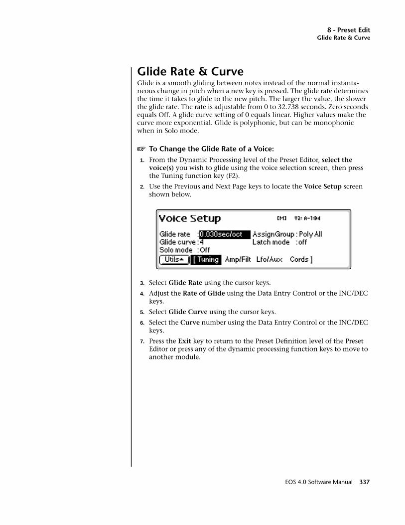
8 - Preset EditGlide Rate & Curve
Glide Rate & CurveGlide is a smooth gliding between notes instead of the normal instanta-neous change in pitch when a new key is pressed. The glide rate determines the time it takes to glide to the new pitch. The larger the value, the slower the glide rate. The rate is adjustable from 0 to 32.738 seconds. Zero seconds equals Off. A glide curve setting of 0 equals linear. Higher values make the curve more exponential. Glide is polyphonic, but can be monophonic when in Solo mode.
v To Change the Glide Rate of a Voice:1. From the Dynamic Processing level of the Preset Editor, select the
voice(s) you wish to glide using the voice selection screen, then press the Tuning function key (F2).
2. Use the Previous and Next Page keys to locate the Voice Setup screen shown below.
3. Select Glide Rate using the cursor keys.
4. Adjust the Rate of Glide using the Data Entry Control or the INC/DEC keys.
5. Select Glide Curve using the cursor keys.
6. Select the Curve number using the Data Entry Control or the INC/DEC keys.
7. Press the Exit key to return to the Preset Definition level of the Preset Editor or press any of the dynamic processing function keys to move to another module.
EOS 4.0 Software Manual 337
8 - Preset EditSolo Modes
Solo ModesSolo mode provides the playing action of a monophonic instrument. It can make wind and string instruments sound more realistic by preventing more than one note from sounding at once. There are eight different solo modes provided which can be used with monophonic synthesizer sounds or to create other performance effects.
Multiple Trigger: Last note priority. No key-up action. Retriggers envelopes and samples when a key is pressed.
Melody (last): Last note priority. No key-up action.
• First solo note: Envelopes start at Attack segment from zero. Samples start at the beginning.
• If previous note is releasing: Envelopes start at Attack segment, but from current level. Samples start at the beginning.
• When playing “Legato”: Envelopes continue from current segment and level. Samples start at the loop or the beginning if unlooped.
Melody (low): Same as Melody (last), but with low-note priority. Newly played keys which are higher than the lowest solo key held will not sound.
Melody (high): Same as Melody (last), but with high-note priority. Newly played keys which are lower than the highest solo key held will not sound.
Synth (last): Similar to Melody (last) with key-up action. When currently sounding solo key is released while still holding other keys, the highest held solo key sounds in a Legato fashion (envelopes not retriggered).
Synth (low): Same as Synth (last), but with low note priority. When the currently sounding solo key is released when other keys are still held, the lowest held solo key will sound in a Legato fashion. (MiniMoog).
•Synth (high): Same as Synth (last), but with high-note priority. When the currently sounding solo key is released when other keys are still held, the highest held solo key will sound in a Legato fashion.
Fingered Glide: Same as Synth (last), except that Glide is disabled when playing Staccato, enabled when playing Legato.
v To Put a Voice into Solo Mode:1. From the Dynamic Processing level of the Preset Editor, select the
voice(s) you wish to place in solo mode using the voice selection screen, then press Tuning (F2).
2. Use the Previous and Next Page keys to locate the Voice Setup screen.
3. Select Solo Mode using the cursor keys.
338 E-MU Systems

8 - Preset EditLatch Mode
4. Select one of the Solo Modes using the Data Entry Control or the INC/DEC keys.
5. Press the Exit key to return to the Preset Definition level of the Preset Editor or press any of the dynamic processing function keys to move to another module.
Latch Mode____ Using Latch Modes together with the Solo Modes may cause unpredictable results.
When Latch mode is On, pressing a key once will latch the key on. Pressing the key again will unlatch the key. This mode was originally designed for doing sound effects work, but you can probably find many other uses for it, such as latching sampled grooves. Any voices assigned to the same key as a latched voice will also latch.
v To Put a Voice into Latch Mode1. From the Dynamic Processing level of the Preset Editor, select the
voice(s) you want to place in solo mode using the voice selection screen, then press the Tuning function key (F2).
2. Use the Previous and Next Page buttons to locate the Voice Setup screen.
3. Select Latch Mode using the cursor buttons.
4. Press the Exit button to return to the Preset Definition level of the Preset Editor or press any of the dynamic processing function keys to move to another module.
EOS 4.0 Software Manual 339
8 - Preset EditAssign Group
Assign GroupThis function allows you to assign a certain number of output channels to each voice. By assigning all voices in the preset to assign groups, important parts can be protected from being “stolen” by more recently played keys. Or, a voice such as an open high hat can be assigned to a mono channel so it will be cancelled by a closed high hat. Voices will rotate within their assigned bin of channels not interfering with other bins. Poly All is the default mode.
The modes are as follows.
• Poly All: Notes are played polyphonically with dynamic channel assignment, using all 128 channels.
• Poly 16 A-B: Two bins of 16 channels each. Notes are played polyphon-ically with dynamic channel assignment, but using no more than 16 channels.
• Poly 8 A-D: Four bins of 8 channels each. Notes are played polyphoni-cally with dynamic channel assignment, but using no more than 8 channels.
• Poly 4 A-D: Four bins of 4 channels each. Notes are played polyphoni-cally with dynamic channel assignment, but using no more than 4 channels.
• Poly 2 A-D: Four bins of 2 channels each. Notes are played polyphoni-cally with dynamic channel assignment, but using no more than 2 channels.
• Mono A-I: Nine monophonic channels. Any voices assigned to the same letter interrupt each other, but does not affect other voices.
v To Assign Voices to a Group:1. From the Dynamic Processing level of the Preset Editor, select the
voice(s) you wish to group using the voice selection screen.
2. Press the Tuning function key (F2).
3. Use the Previous and Next Page buttons to locate the Voice Setup screen.
4. Select Assign Group using the cursor buttons.
5. Select the type of Assign Group using the Data Entry Control or the INC/DEC buttons.
6. Press the Exit button to return to the Preset Definition level of the Preset Editor or press any of the dynamic processing function keys to move to another module.
340 E-MU Systems
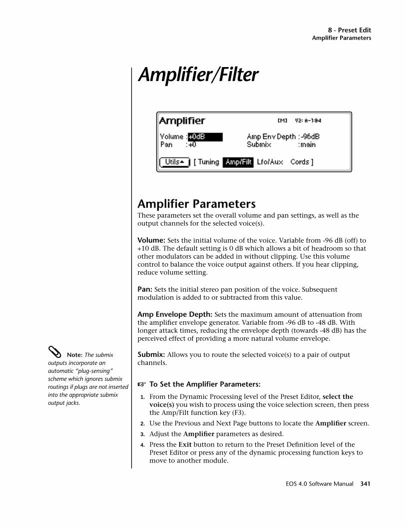
8 - Preset EditAmplifier Parameters
Amplifier/Filter
Amplifier ParametersThese parameters set the overall volume and pan settings, as well as the output channels for the selected voice(s).
Volume: Sets the initial volume of the voice. Variable from -96 dB (off) to +10 dB. The default setting is 0 dB which allows a bit of headroom so that other modulators can be added in without clipping. Use this volume control to balance the voice output against others. If you hear clipping, reduce volume setting.
Pan: Sets the initial stereo pan position of the voice. Subsequent modulation is added to or subtracted from this value.
Amp Envelope Depth: Sets the maximum amount of attenuation from the amplifier envelope generator. Variable from -96 dB to -48 dB. With longer attack times, reducing the envelope depth (towards -48 dB) has the perceived effect of providing a more natural volume envelope.
Note: The submix outputs incorporate an automatic “plug-sensing” scheme which ignores submix routings if plugs are not inserted into the appropriate submix output jacks.
Submix: Allows you to route the selected voice(s) to a pair of output channels.
v To Set the Amplifier Parameters:
1. From the Dynamic Processing level of the Preset Editor, select the voice(s) you wish to process using the voice selection screen, then press the Amp/Filt function key (F3).
2. Use the Previous and Next Page buttons to locate the Amplifier screen.
3. Adjust the Amplifier parameters as desired.
4. Press the Exit button to return to the Preset Definition level of the Preset Editor or press any of the dynamic processing function keys to move to another module.
EOS 4.0 Software Manual 341
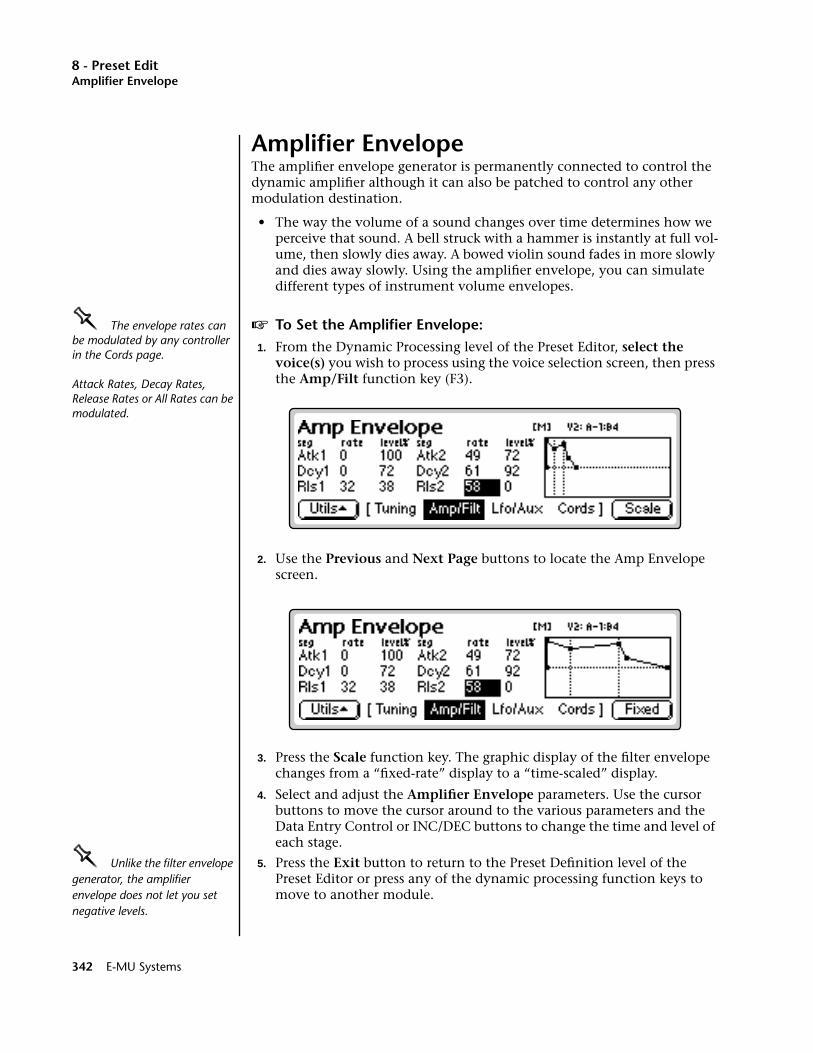
8 - Preset EditAmplifier Envelope
Amplifier EnvelopeThe amplifier envelope generator is permanently connected to control the dynamic amplifier although it can also be patched to control any other modulation destination.
• The way the volume of a sound changes over time determines how we perceive that sound. A bell struck with a hammer is instantly at full vol-ume, then slowly dies away. A bowed violin sound fades in more slowly and dies away slowly. Using the amplifier envelope, you can simulate different types of instrument volume envelopes.
OOOO The envelope rates can be modulated by any controller in the Cords page.
Attack Rates, Decay Rates, Release Rates or All Rates can be modulated.
v To Set the Amplifier Envelope:1. From the Dynamic Processing level of the Preset Editor, select the
voice(s) you wish to process using the voice selection screen, then press the Amp/Filt function key (F3).
2. Use the Previous and Next Page buttons to locate the Amp Envelope screen.
3. Press the Scale function key. The graphic display of the filter envelope changes from a “fixed-rate” display to a “time-scaled” display.
4. Select and adjust the Amplifier Envelope parameters. Use the cursor buttons to move the cursor around to the various parameters and the Data Entry Control or INC/DEC buttons to change the time and level of each stage.
OOOO Unlike the filter envelope generator, the amplifier envelope does not let you set negative levels.
5. Press the Exit button to return to the Preset Definition level of the Preset Editor or press any of the dynamic processing function keys to move to another module.
342 E-MU Systems
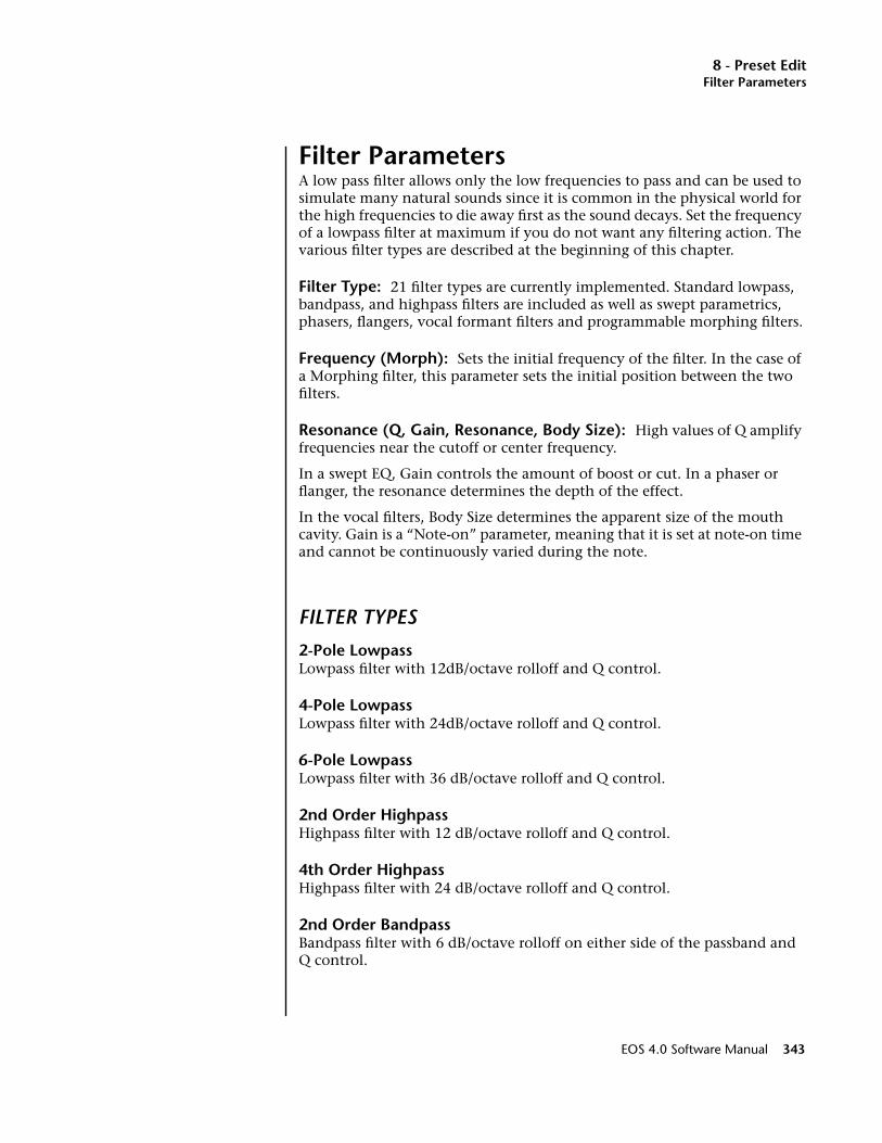
8 - Preset EditFilter Parameters
Filter ParametersA low pass filter allows only the low frequencies to pass and can be used to simulate many natural sounds since it is common in the physical world for the high frequencies to die away first as the sound decays. Set the frequency of a lowpass filter at maximum if you do not want any filtering action. The various filter types are described at the beginning of this chapter.
Filter Type: 21 filter types are currently implemented. Standard lowpass, bandpass, and highpass filters are included as well as swept parametrics, phasers, flangers, vocal formant filters and programmable morphing filters.
Frequency (Morph): Sets the initial frequency of the filter. In the case of a Morphing filter, this parameter sets the initial position between the two filters.
Resonance (Q, Gain, Resonance, Body Size): High values of Q amplify frequencies near the cutoff or center frequency.
In a swept EQ, Gain controls the amount of boost or cut. In a phaser or flanger, the resonance determines the depth of the effect.
In the vocal filters, Body Size determines the apparent size of the mouth cavity. Gain is a “Note-on” parameter, meaning that it is set at note-on time and cannot be continuously varied during the note.
FILTER TYPES
2-Pole LowpassLowpass filter with 12dB/octave rolloff and Q control.
4-Pole LowpassLowpass filter with 24dB/octave rolloff and Q control.
6-Pole LowpassLowpass filter with 36 dB/octave rolloff and Q control.
2nd Order HighpassHighpass filter with 12 dB/octave rolloff and Q control.
4th Order HighpassHighpass filter with 24 dB/octave rolloff and Q control.
2nd Order BandpassBandpass filter with 6 dB/octave rolloff on either side of the passband and Q control.
EOS 4.0 Software Manual 343
8 - Preset EditFilter Parameters
4th Order BandpassBandpass filter with 12 dB/octave rolloff on either side of the passband and Q control.
Contrary BandpassA novel bandpass filter where the frequency peaks and dips cross midway in the frequency range.
Swept EQ, 1-octaveParametric filter with 24 dB of boost or cut and a one octave bandwidth.
Swept EQ, 2->1-octaveParametric filter with 24 dB of boost or cut. The bandwidth of the filter is two octaves wide at the low end of the audio spectrum, gradually changing to one octave wide at the upper end of the spectrum.
Swept EQ, 3->1-octaveParametric filter with 24 dB of boost or cut. The bandwidth of the filter is three octaves wide at the low end of the audio spectrum, gradually changing to one octave wide at the upper end of the spectrum.
Phaser 1Recreates a comb filter effect typical of phase shifters. Frequency moves position of notches. Resonance varies the depth of the notches.
Phaser 2Comb filter with slightly different notch spacing than Phaser 1. Frequency moves position of notches. Resonance varies the depth of the notches.
Bat PhaserPhase shift filter with peaks as well as notches.
Flanger LiteContains three notches. Frequency moves frequency and spacing of notches. Resonance increases flanging depth.
Vocal Ah-Ay-EeVowel formant filter which sweeps from “Ah” sound, through “Ay” sound to “Ee” sound at maximum morph. Body size varies the apparent size of mouth cavity.
OOOO Tip: The second filter parameter (resonance, Q, gain, body size, peak, expression) is controlled by the ‘FilRes parameter in the Cords screen.
Vocal Oo-AhVowel formant filter which sweeps from “Oo” sound, through “Oh” sound to “Ah” sound at maximum morph. Body size varies the size of mouth cavity.
344 E-MU Systems
8 - Preset EditFilter Parameters
Dual EQ MorphThis is a programmable 2-frame Morphing filter with two EQ sections. As the Morph value is increased, the filter interpolates from the low to high settings. The Gain of each section remains constant during the Morph, but can be scaled at note-on time by controlling the Initial Gain parameter. This filter can be used to create your own vocal formant filters.
2EQ + Lowpass MorphThis unusual filter has two EQ sections and a lowpass filter whose Fc is also controlled by the Morph parameter. The Lowpass filter is completely open at a setting of 255. As the Morph value is increased, the filter interpolates from the low to high settings and the lowpass filter allows more high frequencies to pass. The Q of the lowpass filter has an initial setting and can be also modulated at note-on time.
2EQ Morph + ExpressionThis filter also has two EQ sections and a lowpass filter with independent control over the lowpass filter frequency (Expression). This allows you to use velocity (for example) to control expressive timbre via the lowpass filter, while the Morph parameter is modulated for another effect. As the Morph value is increased, the filter interpolates from the low to high settings.
Peak/Shelf MorphOOOO Tip: The Morphing filters allow high resonance values without losing bass power.
This 2-frame morphing filter offers independent control over frequency, shelving and peak for each of the two filter “frames”. The Peak parameter can also be scaled at note-on time by controlling the Initial Peak parameter.
When the Shelf parameter is negative, the filter will have a low shelving response. When the Shelf parameter is positive, the filter will assume a high shelving response. With Shelf at zero, the filter assumes a peak filter response.
• Note that the two frames of this filter are displayed from left to right unlike the frames of the other morphing filters which are displayed low to high.
v To Set the Filter Parameters:1. From the Dynamic Processing level of the Preset Editor, select the
voice(s) you wish to process using the voice selection screen, then press the Amp/Filt function key (F3).
2. Use the Previous and Next Page buttons to locate the Filter screen.
3. Adjust the Filter parameters as desired. The filter envelope, the filter envelope amount (adjusted in the Cords screen), and the initial filter parameters all interact.
4. Press the Exit button to return to the Preset Definition level of the Preset Editor or press any of the dynamic processing function keys to move to another module.
EOS 4.0 Software Manual 345
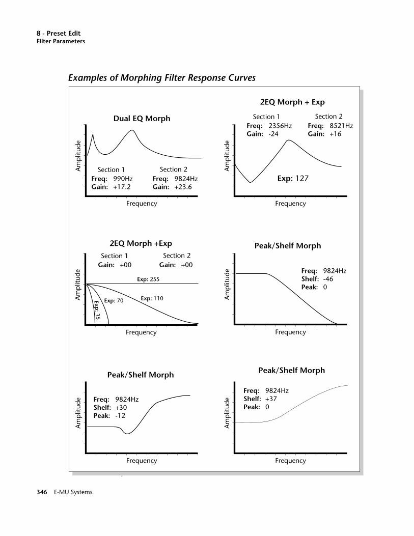
8 - Preset EditFilter Parameters
Dual EQ Morph
Freq:Gain:
990Hz+17.2
Freq:Gain:
9824Hz+23.6
Section 1 Section 2
Frequency
Am
plit
ude
Frequency
Am
plit
ude
Gain: +00 Gain: +00Section 1 Section 2
Exp: 255
Exp: 110Exp: 70Exp: 35
2EQ Morph +Exp
Freq:Gain:
2356Hz-24
Freq:Gain:
8521Hz+16
Frequency
Am
plit
ude
2EQ Morph + Exp
Section 1 Section 2
Exp: 127
Freq:Shelf:Peak:
9824Hz-460
Frequency
Am
plit
ude
Peak/Shelf Morph
Freq:Shelf:Peak:
9824Hz+30-12
Frequency
Am
plit
ude
Peak/Shelf Morph
Freq:Shelf:Peak:
9824Hz+370
Frequency
Am
plit
ude
Peak/Shelf Morph
Examples of Morphing Filter Response Curves
346 E-MU Systems

8 - Preset EditFilter Envelope
Filter EnvelopeThe Filter Envelope is usually assigned to control the filter cutoff parameter although it can be patched to any modulation destination.
v To Set the Filter Envelope:1. From the Dynamic Processing level of the Preset Editor, select the
voice(s) you wish to process using the voice selection screen, then press the Amp/Filt function key (F3).
2. Use the Previous and Next Page buttons to locate the Filter Envelope screen.
OOOO For more information on the Filter Envelope see Background: Programming Basics at the beginning of this section.
3. Press the Scale function key. The graphic display of the filter envelope changes from a “fixed-rate” display to a “time-scaled” display. Use the display view that works best for the envelope you are using.
4. Select and adjust the Filter Envelope parameters. Use the cursor buttons to move the cursor around to the various parameters and the Data Entry Control or INC/DEC buttons to change the time and level of each stage.
• The filter envelope allows you to set negative levels. When patched to the filter cutoff frequency, this useful feature allows the envelope to lower the cutoff frequency below the initial setting.
5. Press the Exit button to return to the Preset Definition level of the Preset Editor or press any of the dynamic processing function keys to move to another module.
EOS 4.0 Software Manual 347
8 - Preset EditLFO/Auxiliary Envelope
LFO/Auxiliary Envelope
• Delay: Sets the amount of time between playing a key and the onset of modulation. This can be used to simulate an effect often used by acous-tic instrument players, where the vibrato is brought in only after the initial note pitch has been established. The delay range is adjustable from 0 seconds to 20 seconds.
• Shape: Sets the LFO waveshape which determines the effect of the LFO. There are 16 LFO waveforms and a random, sample & hold type of wave which outputs random levels at the LFO rate. The LFO waveforms are diagrammed on the following page.
• Variation: Sets the amount of random variation on an LFO each time a key is pressed. This function is useful for ensemble effects, where each note played has a slightly different modulation rate. The higher the number, the greater the note to note variation in the LFOs.
• Sync: Key Sync or Free Running. With key sync selected the LFO wave starts at the beginning of its cycle at each key depression. In free run mode, the LFO wave begins at a random point in its cycle on each key depression.
v To Program an LFO:1. From the Dynamic Processing level of the Preset Editor, select the
voice(s) you wish to process using the voice selection screen, then press the LFO/Aux function key (F4).
2. Use the Previous and Next Page buttons to locate the LFO 1 or LFO 2 screen.
3. Adjust the LFO parameters as desired.
4. Press the Exit button to return to the Preset Definition level of the Preset Editor or press any of the dynamic processing function keys to move to another module.
348 E-MU Systems

8 - Preset EditLag Processors
Lag ProcessorsThe LFO 2 screen contains controls for the two lag processors used in the modulation Cords screens. Lag processors can be inserted in a modulation patch to inhibit rapid changes in the modulation source or cause it to lag behind the input. The amount (rate) of lag is adjustable from 0 to 10. A setting of O will cause the least amount of lag. 10 is the slowest lag. The diagram on the following page shows one way that a lag processor might be used.
LFO WaveshapesTriangle
Square
Sine 1,2 Sine 1,3,5
Sine
Sawtooth
25% Pulse
33% Pulse
12% Pulse16% Pulse
Random
Pat: Fifth+Octave
C
CG
Pat: Octaves+ Octave
- OctaveC
FG
Pat: Sus4 trip
C
G
A#
Pat: Neener
Hemi-quaver Sine + Noise
EOS 4.0 Software Manual 349
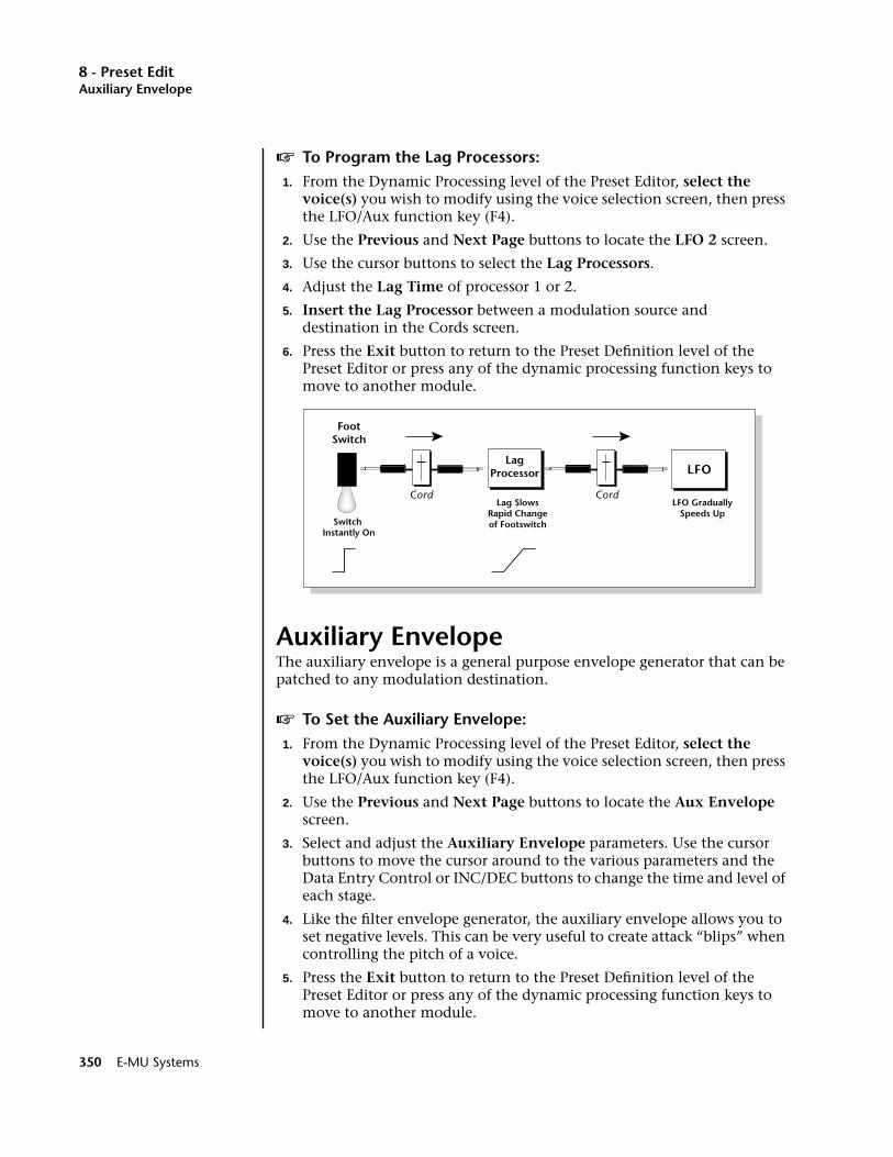
8 - Preset EditAuxiliary Envelope
v To Program the Lag Processors:1. From the Dynamic Processing level of the Preset Editor, select the
voice(s) you wish to modify using the voice selection screen, then press the LFO/Aux function key (F4).
2. Use the Previous and Next Page buttons to locate the LFO 2 screen.
3. Use the cursor buttons to select the Lag Processors.
4. Adjust the Lag Time of processor 1 or 2.
5. Insert the Lag Processor between a modulation source and destination in the Cords screen.
6. Press the Exit button to return to the Preset Definition level of the Preset Editor or press any of the dynamic processing function keys to move to another module.
Auxiliary EnvelopeThe auxiliary envelope is a general purpose envelope generator that can be patched to any modulation destination.
v To Set the Auxiliary Envelope:1. From the Dynamic Processing level of the Preset Editor, select the
voice(s) you wish to modify using the voice selection screen, then press the LFO/Aux function key (F4).
2. Use the Previous and Next Page buttons to locate the Aux Envelope screen.
3. Select and adjust the Auxiliary Envelope parameters. Use the cursor buttons to move the cursor around to the various parameters and the Data Entry Control or INC/DEC buttons to change the time and level of each stage.
4. Like the filter envelope generator, the auxiliary envelope allows you to set negative levels. This can be very useful to create attack “blips” when controlling the pitch of a voice.
5. Press the Exit button to return to the Preset Definition level of the Preset Editor or press any of the dynamic processing function keys to move to another module.
LagProcessor
FootSwitch
LFO
Cord CordLag Slows
Rapid Changeof FootswitchSwitch
Instantly On
LFO GraduallySpeeds Up
350 E-MU Systems
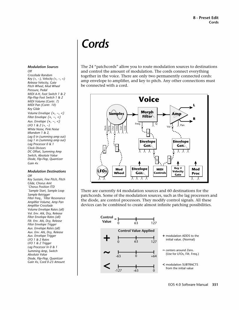
8 - Preset EditCords
Cords
The 24 “patchcords” allow you to route modulation sources to destinations and control the amount of modulation. The cords connect everything together in the voice. There are only two permanently connected cords: amp envelope to amplifier, and key to pitch. Any other connections must be connected with a cord.
There are currently 64 modulation sources and 60 destinations for the patchcords. Some of the modulation sources, such as the lag processors and the diode, are control processors. They modify control signals. All these devices can be combined to create almost infinite patching possibilities.
Samples Amp
L
R
LFOs EnvelopeGen.
EnvelopeGen.
EnvelopeGen.
ModProc
ModWheel
MIDIControls
Key #Velocity
Gate
Retr
ig
Pitc
h
Loop
Freq QVol
Pan
Cho
r
Glid
e
Star
t
Voice
MorphFilter
+~
+ modulation ADDS to the initial value. (Normal)
< modulation SUBTRACTS from the initial value
~ centers around Zero. (Use for LFOs, Filt. Freq.)
ControlValue
Control Value Applied
0 12763
0 12763
-63 +640
-127 0-63<
Modulation SourcesOffCrossfade RandomKey (+, ~), Velocity (+, ~, <)Release Velocity, GatePitch Wheel, Mod WheelPressure, PedalMIDI A-H, Foot Switch 1 & 2Flip-Flop Foot Switch 1 & 2MIDI Volume (Contr. 7)MIDI Pan (Contr. 10)Key GlideVolume Envelope (+, ~, <)Filter Envelope (+, ~, <)Aux. Envelope (+, ~, <)LFO 1 & 2 (+, ~)White Noise, Pink NoisekRandom 1 & 2,Lag 0 in (summing amp out)Lag 1 in (summing amp out)Lag Processor 0 & 1Clock DivisorsDC Offset, Summing AmpSwitch, Absolute ValueDiode, Flip-Flop, QuantizerGain 4x
Modulation DestinationsOffKey Sustain, Fine Pitch, PitchGlide, Chorus Amt`Chorus Position ITD`Sample Start, Sample LoopSample RetriggerFilter Freq., `Filter ResonanceAmplifier Volume, Amp PanAmplifier CrossfadeVolume Envelope Rates (all)Vol. Env. Atk, Dcy, ReleaseFilter Envelope Rates (all)Filt. Env. Atk, Dcy, ReleaseFilter Envelope TriggerAux. Envelope Rates (all)Aux. Env. Atk, Dcy, ReleaseAux. Envelope TriggerLFO 1 & 2 RatesLFO 1 & 2 TriggerLag Processor In 0 & 1Summing Amp, SwitchAbsolute ValueDiode, Flip-Flop, QuantizerGain 4x, Cord 0-23 Amount
EOS 4.0 Software Manual 351
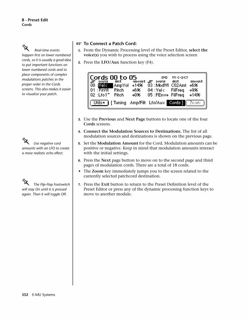
8 - Preset EditCords
v To Connect a Patch Cord:OOOO Real-time events happen first on lower numbered cords, so it is usually a good idea to put important functions on lower numbered cords and to place components of complex modulations patches in the proper order in the Cords screens. This also makes it easier to visualize your patch.
1. From the Dynamic Processing level of the Preset Editor, select the voice(s) you wish to process using the voice selection screen
2. Press the LFO/Aux function key (F4).
3. Use the Previous and Next Page buttons to locate one of the four Cords screens.
4. Connect the Modulation Sources to Destinations. The list of all modulation sources and destinations is shown on the previous page.
OOOO Use negative cord amounts with an LFO to create a more realistic echo effect.
5. Set the Modulation Amount for the Cord. Modulation amounts can be positive or negative. Keep in mind that modulation amounts interact with the initial settings.
6. Press the Next page button to move on to the second page and third pages of modulation cords. There are a total of 18 cords.
• The Zoom key immediately jumps you to the screen related to the currently selected patchcord destination.
OOOO The Flip-Flop Footswitch will stay On until it is pressed again. Then it will toggle Off.
7. Press the Exit button to return to the Preset Definition level of the Preset Editor or press any of the dynamic processing function keys to move to another module.
352 E-MU Systems
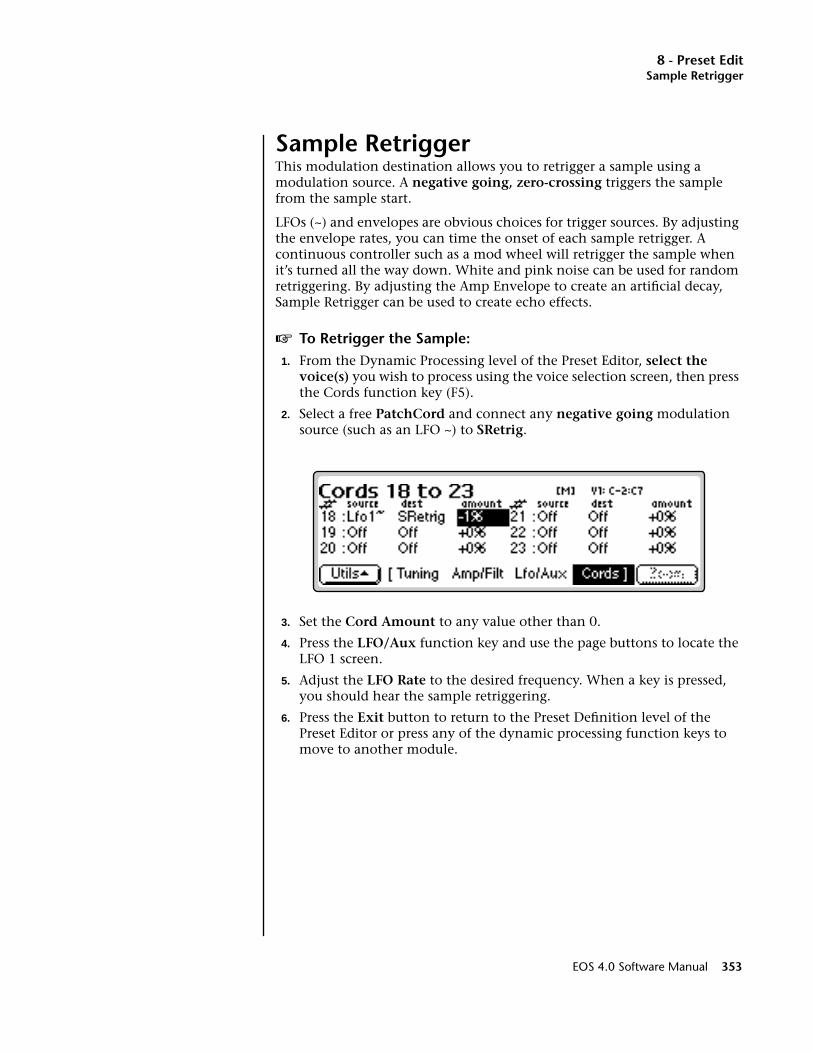
8 - Preset EditSample Retrigger
Sample RetriggerThis modulation destination allows you to retrigger a sample using a modulation source. A negative going, zero-crossing triggers the sample from the sample start.
LFOs (~) and envelopes are obvious choices for trigger sources. By adjusting the envelope rates, you can time the onset of each sample retrigger. A continuous controller such as a mod wheel will retrigger the sample when it’s turned all the way down. White and pink noise can be used for random retriggering. By adjusting the Amp Envelope to create an artificial decay, Sample Retrigger can be used to create echo effects.
v To Retrigger the Sample:1. From the Dynamic Processing level of the Preset Editor, select the
voice(s) you wish to process using the voice selection screen, then press the Cords function key (F5).
2. Select a free PatchCord and connect any negative going modulation source (such as an LFO ~) to SRetrig.
3. Set the Cord Amount to any value other than 0.
4. Press the LFO/Aux function key and use the page buttons to locate the LFO 1 screen.
5. Adjust the LFO Rate to the desired frequency. When a key is pressed, you should hear the sample retriggering.
6. Press the Exit button to return to the Preset Definition level of the Preset Editor or press any of the dynamic processing function keys to move to another module.
EOS 4.0 Software Manual 353

8 - Preset Edit
354 E-MU Systems

9 - Disk Menu
9Disk Menu
EOS 4.0 Software Manual 355

9 - Disk Menu
356 E-MU Systems
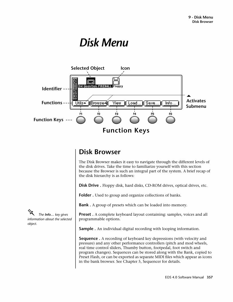
9 - Disk MenuDisk Browser
Disk Menu
Disk BrowserThe Disk Browser makes it easy to navigate through the different levels of the disk drives. Take the time to familiarize yourself with this section because the Browser is such an integral part of the system. A brief recap of the disk hierarchy is as follows:
Disk Drive . Floppy disk, hard disks, CD-ROM drives, optical drives, etc.
Folder . Used to group and organize collections of banks.
Bank . A group of presets which can be loaded into memory.
OOOO The Info… key gives information about the selected object.
Preset . A complete keyboard layout containing: samples, voices and all programmable options.
Sample . An individual digital recording with looping information.
Sequence . A recording of keyboard key depressions (with velocity and pressure) and any other performance controllers (pitch and mod wheels, real time control sliders, Thumby button, footpedal, foot switch and program changes). Sequences can be stored along with the Bank, copied to Preset Flash, or can be exported as separate MIDI files which appear as icons in the bank browser. See Chapter 5, Sequencer for details.
Function Keys
Icon
Identifier
Selected Object
ActivatesSubmenu
Functions
Function Keys
EOS 4.0 Software Manual 357

9 - Disk MenuDisk Browser
v To Browse the Disk:1. Press the Disk/Browse key. The LED illuminates and the screen shown
below appears.OOOO To turn Sprint mode On from the preset menu, press Sprint (F5).
2. Press the View function key (F3). The display now changes to a list format. Press the View key again to return to the icon display.
3. Press the Info… function key (F6). A pop-up window appears with information about the hard disk drive. Press OK to return.
OOOO The Disk Key can be set to call up either SoundSprint mode or the Last screen you used in the Disk Browser. This preference is located under Master, Setup, SCSI.
4. Press the Browse function key (F2). A second row of function keys appears.
5. Press the Folders function key. The folders on the hard disk will be shown.
358 E-MU Systems
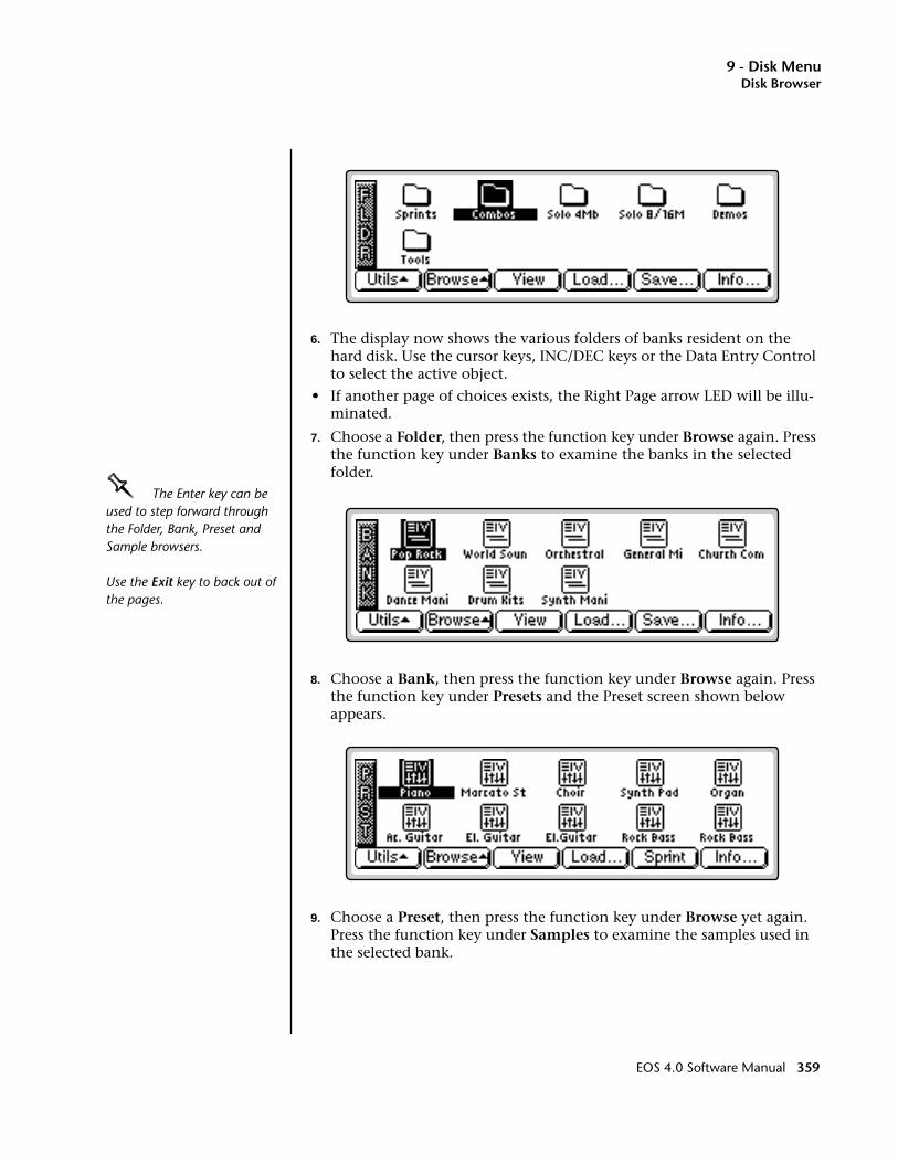
9 - Disk MenuDisk Browser
6. The display now shows the various folders of banks resident on the hard disk. Use the cursor keys, INC/DEC keys or the Data Entry Control to select the active object.
• If another page of choices exists, the Right Page arrow LED will be illu-minated.
7. Choose a Folder, then press the function key under Browse again. Press the function key under Banks to examine the banks in the selected folder.
OOOO The Enter key can be used to step forward through the Folder, Bank, Preset and Sample browsers.
Use the Exit key to back out of the pages.
8. Choose a Bank, then press the function key under Browse again. Press the function key under Presets and the Preset screen shown below appears.
9. Choose a Preset, then press the function key under Browse yet again. Press the function key under Samples to examine the samples used in the selected bank.
EOS 4.0 Software Manual 359
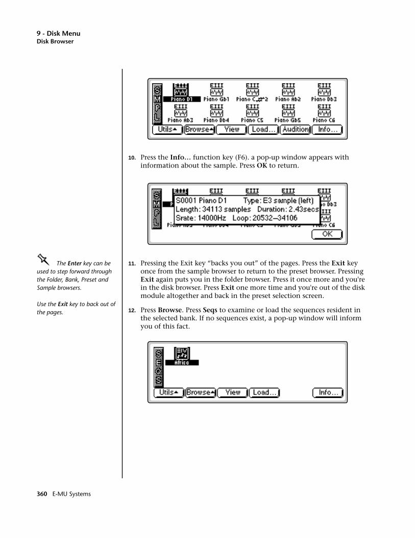
9 - Disk MenuDisk Browser
10. Press the Info… function key (F6). a pop-up window appears with information about the sample. Press OK to return.
OOOO The Enter key can be used to step forward through the Folder, Bank, Preset and Sample browsers.
Use the Exit key to back out of the pages.
11. Pressing the Exit key “backs you out” of the pages. Press the Exit key once from the sample browser to return to the preset browser. Pressing Exit again puts you in the folder browser. Press it once more and you're in the disk browser. Press Exit one more time and you're out of the disk module altogether and back in the preset selection screen.
12. Press Browse. Press Seqs to examine or load the sequences resident in the selected bank. If no sequences exist, a pop-up window will inform you of this fact.
360 E-MU Systems
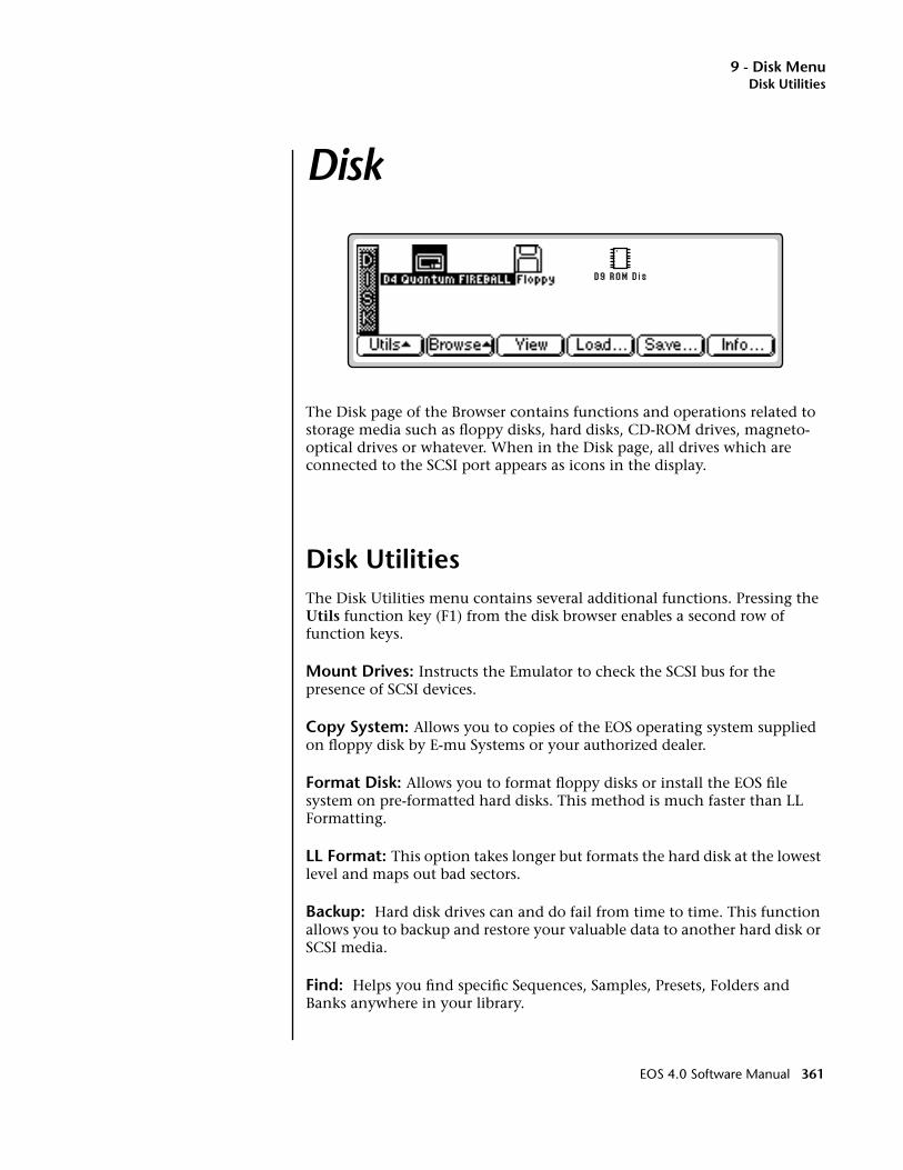
9 - Disk MenuDisk Utilities
Disk
The Disk page of the Browser contains functions and operations related to storage media such as floppy disks, hard disks, CD-ROM drives, magneto-optical drives or whatever. When in the Disk page, all drives which are connected to the SCSI port appears as icons in the display.
Disk UtilitiesThe Disk Utilities menu contains several additional functions. Pressing the Utils function key (F1) from the disk browser enables a second row of function keys.
Mount Drives: Instructs the Emulator to check the SCSI bus for the presence of SCSI devices.
Copy System: Allows you to copies of the EOS operating system supplied on floppy disk by E-mu Systems or your authorized dealer.
Format Disk: Allows you to format floppy disks or install the EOS file system on pre-formatted hard disks. This method is much faster than LL Formatting.
LL Format: This option takes longer but formats the hard disk at the lowest level and maps out bad sectors.
Backup: Hard disk drives can and do fail from time to time. This function allows you to backup and restore your valuable data to another hard disk or SCSI media.
Find: Helps you find specific Sequences, Samples, Presets, Folders and Banks anywhere in your library.
EOS 4.0 Software Manual 361
9 - Disk MenuMount Drives
Mount Drives____ ALWAYS re-mount a removable media drive after swapping disks.
This utility checks the SCSI bus for the presence of SCSI devices. Use this function whenever a connected SCSI device does not appear in the Disk Browser or whenever you swap cartridges from a removable media disk drive.
v To Mount Drives:1. From the Disk Browser, press the Utilities function key (F1).
2. Press the Mount function key (F1). The Emulator will mount all SCSI devices.
Copy SystemFrom time to time the EOS operating system will be updated with new features and functions. This software is usually distributed on floppy disk and can be permanently copied into the Emulator's Flash RAM so that it will automatically load whenever you turn on the Emulator. Software can also be saved to a floppy disk in order to back it up.
Each version of software is numbered and is indicated when you select “About” under the “Utilities” menu in the Master module. Copying software will not affect any other data such as samples or presets.
v To Update the EOS Software:1. Turn off power to the Emulator.
2. Insert the software floppy disk with the label side left (label side up on the E4K or E-Synth Keyboard).
3. Turn on power to the Emulator. The display will show the software version on the floppy and ask if you wish to update Flash RAM from the floppy software.
4. Press Enter to update, or Exit to cancel the operation.____ Caution: Re-initializing EEPROM resets the “Avoid Host on SCSI ID” parameter to “None”. If you have a computer on the SCSI bus, be sure to set this parameter to the correct ID.
5. Re-initialize EEPROM. (This should be done after a software update to “clean the slate”. It resets the Master menu preferences and other bits.)a. Press Master, Utils, Testsb. Enter the Secret Password: 1-3-5-8, then press OK.c. Press More, then InitEE The display reads, “Initialize EE?”d. Press OK. The display reads, “Saving System”. Press Master to exit.
6. Recalibrate the Emulator controls. See “Recalibration” on page 68.
v To Backup the EOS Software to Floppy Disk:1. From the Drives Browser, press the Utilities function key (F1).
2. Press the CopySys function key (F2). The display will ask you to insert a floppy disk. Insert a formatted floppy disk label side left (label side up on the E4K or E-Synth Keyboard). If the floppy disk is unformatted, you will be asked if you want to format it.)
3. Press Yes to copy the system to the floppy disk. Press Cancel or Exit to cancel the operation and return to the disk browser.
362 E-MU Systems
9 - Disk MenuFormat Disk
Format DiskBefore a new floppy disk or hard disk can record or store any data, it must be told how to record this data. This is called formatting. The floppy disk formatting procedure should be run on any new disk, or on recycled disks previously used with other systems (such as personal computers) since these will not be formatted correctly. If the hard disk drive is not shown in the disk browser, use the Mount Drive function.
EOS can read both EOS and DOS formatted floppies. DOS floppies can be formatted on PCs or Mac computers
EOS floppies can hold only one bank per disk, but can use multiple disks to hold large banks.
DOS floppies can hold up to 50 small files and so are a good choice for storing small banks and MIDI sequences. However, you cannot save a large file onto multiple DOS floppies.
Many new hard disk and optical drives as well as removable hard disk cartridges now come pre-formatted. This function allows you to install the EOS file system on pre-formatted hard disks without having to reformat the disk. This can save quite some time, especially with large capacity disks. To find out if a disk is pre-formatted, try the Format Disk procedure first. If this doesn't work, use the Low Level Format procedure.
v To Format a Floppy Disk:1. From the Disk Browser, select the floppy drive using the Data Entry
Control, cursor keys or INC/DEC keys.
2. Press the Utilities function key (F1).
3. Press the Format function key (F3). The display will ask you to insert a floppy disk. Insert a floppy disk with the label side toward the center of the Emulator (label side up on the E4K or E-Synth Keyboard).
4. Consider the implications of your action. Formatting a floppy disk erases all information on that disk, completely. Press OK to format the disk or Cancel to cancel the operation. Formatting takes about two minutes.
5. After formatting the floppy disk, format another if desired. The display will ask you if you want to format another floppy. To do this, press Yes, remove the current disk, insert a new disk and press OK. Otherwise, press Cancel or Exit to cancel the operation and return to the disk browser.
v To Format a Hard Disk or Optical Disk:1. From the Disk Browser, select the desired SCSI drive using the Data
Entry Control, cursor keys or INC/DEC keys.
2. Press the Utilities function key (F1).
3. Press the Format function key (F3). The display will warn you if you are about to destroy data.
4. Press OK to Install the file system on the disk or Cancel to cancel the operation. Installing the file system time takes a minute or more, depending on the size of the disk.
EOS floppy icon
DOS floppy icon
EOS 4.0 Software Manual 363

9 - Disk MenuLow Level Format
Low Level FormatLow Level Formatting formats the disk at the lowest level and attempts to map out any bad sectors. When connecting a new disk, always try the regular format procedure first as this saves considerable time.
v To Low Level Format a Hard Disk or Optical Disk:1. From the Disk Browser, select the desired SCSI drive using the Data
Entry Control, cursor keys or INC/DEC keys.
2. Press the Utilities function key (F1).
3. Press the LLFormat function key (F4). The display will warn you if you are about to destroy data.
4. Press OK to format the disk or Cancel to cancel the operation. Formatting time varies depending on the size of the disk.
BackupThis function allows you to backup and restore a portion or the entire contents of the hard disk. You should develop the habit of backing up any and all important data or risk catastrophe at some future date. If you'd hate to lose it, BACK IT UP!
v To Backup your Hard Disk Data:1. From the Disk Browser, select the SCSI drive you want to back up using
the cursor keys, INC/DEC keys or the Data Entry Control.
2. Press the Utils function key (F1).
3. Press the Backup function key (F5). The display will warn you if you are about to overwrite the current bank in RAM.
4. Press OK to continue or Cancel to cancel the operation. The following screen appears.
5. Select the destination drive using the INC/DEC keys, or Data Entry Control.
6. Move the cursor down to “Backup Type” and select the type of Backup Type with the INC/DEC keys or Data Entry Control.
364 E-MU Systems

9 - Disk MenuBackup
Use “Same as Source” when backing up to an ESI-32 or EIIIX drive if you want these machines to see your EOS files. They will overwrite any files stored in those locations. The ESI-32 and EIIIX cannot load EOS files, but the drive can be used for both machines. Use “Use Empty” if backing up to an ESI-32 or EIIIX drive and you want the EOS files to be invisible to those machines. In this case, ESI or EIIIX files will not be overwritten.
Your choices are:
• All: Transfers all banks from the source disk to the destination disk.
• Range: Transfers a selected range of banks from the source disk to the destination disk.
• Incremental: Transfers only those banks which have been modified since the last backup.
Incremental Backup works by turning on a “bit” (stored with the bank) whenever a bank is created or modified. Whenever you backup the bank, the bit is turned off. Because the bit is turned off on the first backup, do not use incremental backup if you want to make multiple backup disks.
7. Move the cursor down to “Destination folder/bank numbers” to select where the banks will be placed on the destination disk.
Your choices are:
• Same as Source: Copies the banks into the same numbered bank locations on the destination disk.
• Use Empty: Copies the banks into a new folder on the destination disk.
8. When you have made your choices, press OK to continue or Cancel to cancel the operation. Choosing All or Incremental causes the backup to begin immediately. Choosing “Range”, causes the following screen to appear.
9. Select the Folder to be copied.
10. Select the Starting and Ending banks of the range to be copied, then press Backup.
v To Restore your Hard Disk Data:• Select your Backup Disk in the disk browser and simply backup to
your regular work disk.
EOS 4.0 Software Manual 365
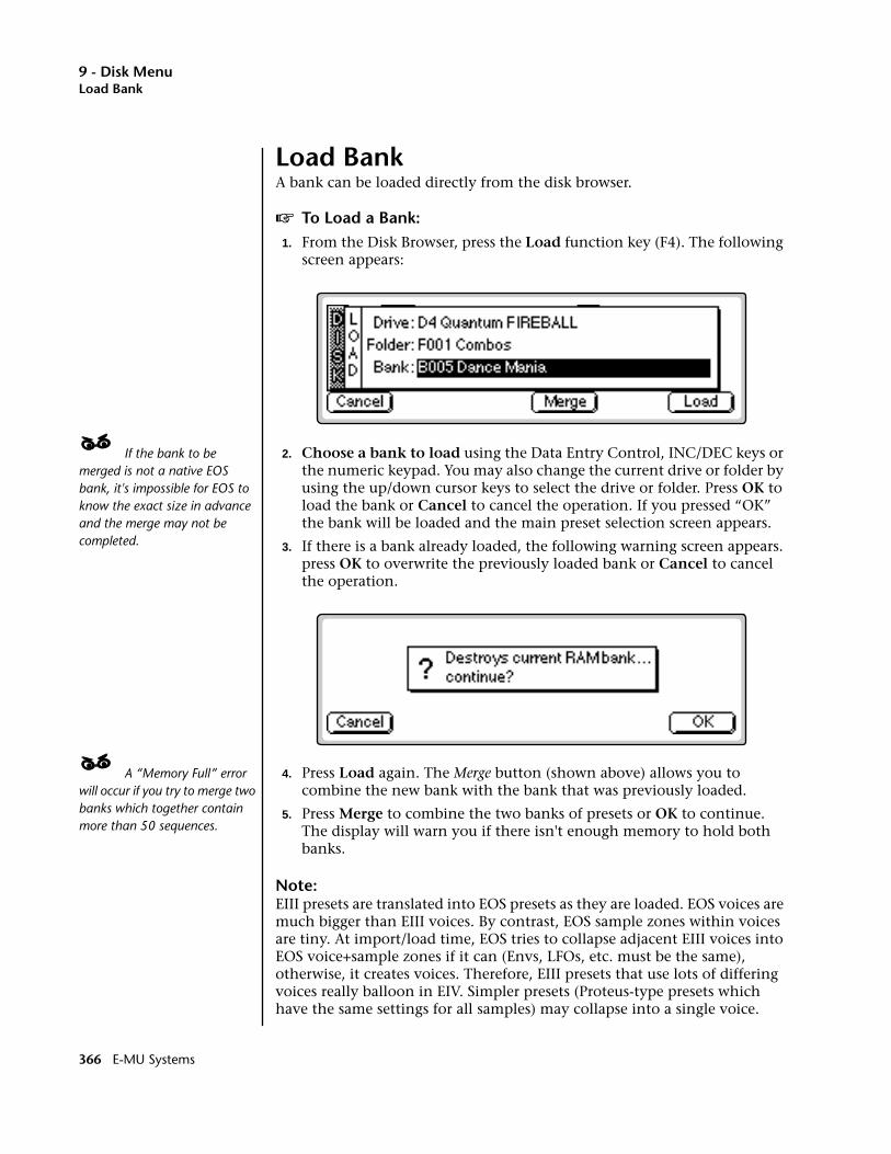
9 - Disk MenuLoad Bank
Load BankA bank can be loaded directly from the disk browser.
v To Load a Bank:1. From the Disk Browser, press the Load function key (F4). The following
screen appears:
____ If the bank to be merged is not a native EOS bank, it's impossible for EOS to know the exact size in advance and the merge may not be completed.
2. Choose a bank to load using the Data Entry Control, INC/DEC keys or the numeric keypad. You may also change the current drive or folder by using the up/down cursor keys to select the drive or folder. Press OK to load the bank or Cancel to cancel the operation. If you pressed “OK” the bank will be loaded and the main preset selection screen appears.
3. If there is a bank already loaded, the following warning screen appears. press OK to overwrite the previously loaded bank or Cancel to cancel the operation.
____ A “Memory Full” error will occur if you try to merge two banks which together contain more than 50 sequences.
4. Press Load again. The Merge button (shown above) allows you to combine the new bank with the bank that was previously loaded.
5. Press Merge to combine the two banks of presets or OK to continue. The display will warn you if there isn't enough memory to hold both banks.
Note: EIII presets are translated into EOS presets as they are loaded. EOS voices are much bigger than EIII voices. By contrast, EOS sample zones within voices are tiny. At import/load time, EOS tries to collapse adjacent EIII voices into EOS voice+sample zones if it can (Envs, LFOs, etc. must be the same), otherwise, it creates voices. Therefore, EIII presets that use lots of differing voices really balloon in EIV. Simpler presets (Proteus-type presets which have the same settings for all samples) may collapse into a single voice.
366 E-MU Systems
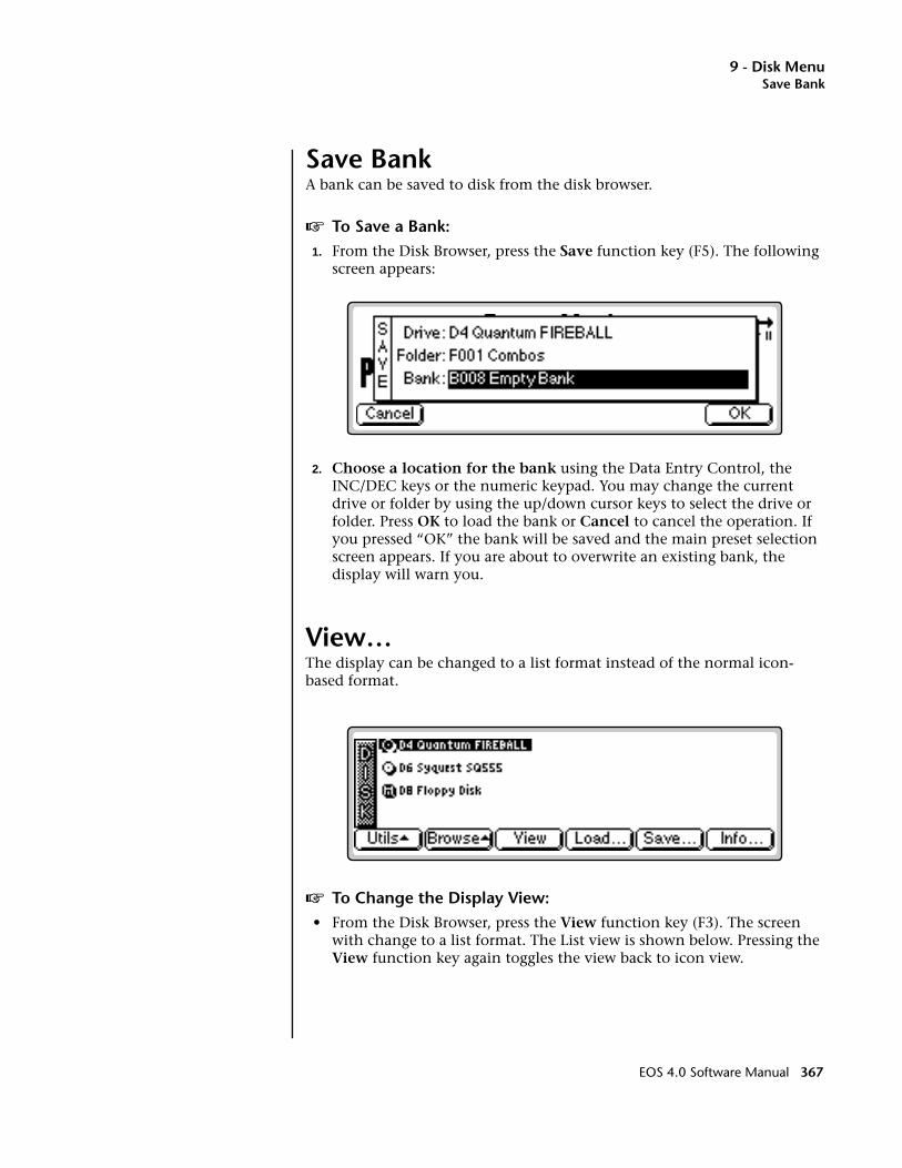
9 - Disk MenuSave Bank
Save BankA bank can be saved to disk from the disk browser.
v To Save a Bank:1. From the Disk Browser, press the Save function key (F5). The following
screen appears:
2. Choose a location for the bank using the Data Entry Control, the INC/DEC keys or the numeric keypad. You may change the current drive or folder by using the up/down cursor keys to select the drive or folder. Press OK to load the bank or Cancel to cancel the operation. If you pressed “OK” the bank will be saved and the main preset selection screen appears. If you are about to overwrite an existing bank, the display will warn you.
View…The display can be changed to a list format instead of the normal icon-based format.
v To Change the Display View:• From the Disk Browser, press the View function key (F3). The screen
with change to a list format. The List view is shown below. Pressing the View function key again toggles the view back to icon view.
EOS 4.0 Software Manual 367
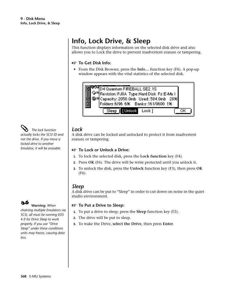
9 - Disk MenuInfo, Lock Drive, & Sleep
Info, Lock Drive, & SleepThis function displays information on the selected disk drive and also allows you to Lock the drive to prevent inadvertent erasure or tampering.
v To Get Disk Info:• From the Disk Browser, press the Info… function key (F6). A pop-up
window appears with the vital statistics of the selected disk.
The lock function actually locks the SCSI ID and not the drive. If you move a locked drive to another Emulator, it will be erasable.
LockA disk drive can be locked and unlocked to protect it from inadvertent erasure or tampering.
v To Lock or Unlock a Drive:1. To lock the selected disk, press the Lock function key (F4).
2. Press OK (F6). The drive will be write protected until you unlock it.
3. To unlock the disk, press the Unlock function key (F3), then press OK (F6).
SleepA disk drive can be put to “Sleep” in order to cut down on noise in the quiet studio environment.
____ Warning: When chaining multiple Emulators via SCSI, all must be running EOS 4.0 for Drive Sleep to work properly. If you use “Drive Sleep” under these conditions units may freeze, causing data loss.
v To Put a Drive to Sleep:1. To put a drive to sleep, press the Sleep function key (F2).
2. The drive will be put to sleep.
3. To wake the Drive, select the Drive, then press Enter.
368 E-MU Systems

9 - Disk MenuFolder Utilities
Folder
Folders help you organize your banks of sounds by providing another level between the bank and disk level. You may want to organize your banks by a particular project or by the type of sounds contained within, such as: Sound Effects, Pianos, Strings, etc. If you do not wish to use folders, simply place everything on the disk into one folder. You can skip over the folder level in the browser and forget that folders even exist.
Folder UtilitiesThe Folder Utilities menu contains several additional functions. Pressing the Utils function key (F1) from the folder browser enables a second row of function keys.
New: Allows you to create a new folder.
Delete: Allows you to delete an unwanted folder
Rename: Allows you to rename the selected folder
Find: Allows you to search your disk(s) for a particular folder.
NewThis utility allows you to create a new folder.
v To Create a New Folder:1. From the Folder Browser, press the Utilities function key (F1).
2. Press the New function key (F2). A pop-up window appears prompting you to name your new folder.
3. Press OK after naming the new folder and it appears on the screen.
EOS 4.0 Software Manual 369
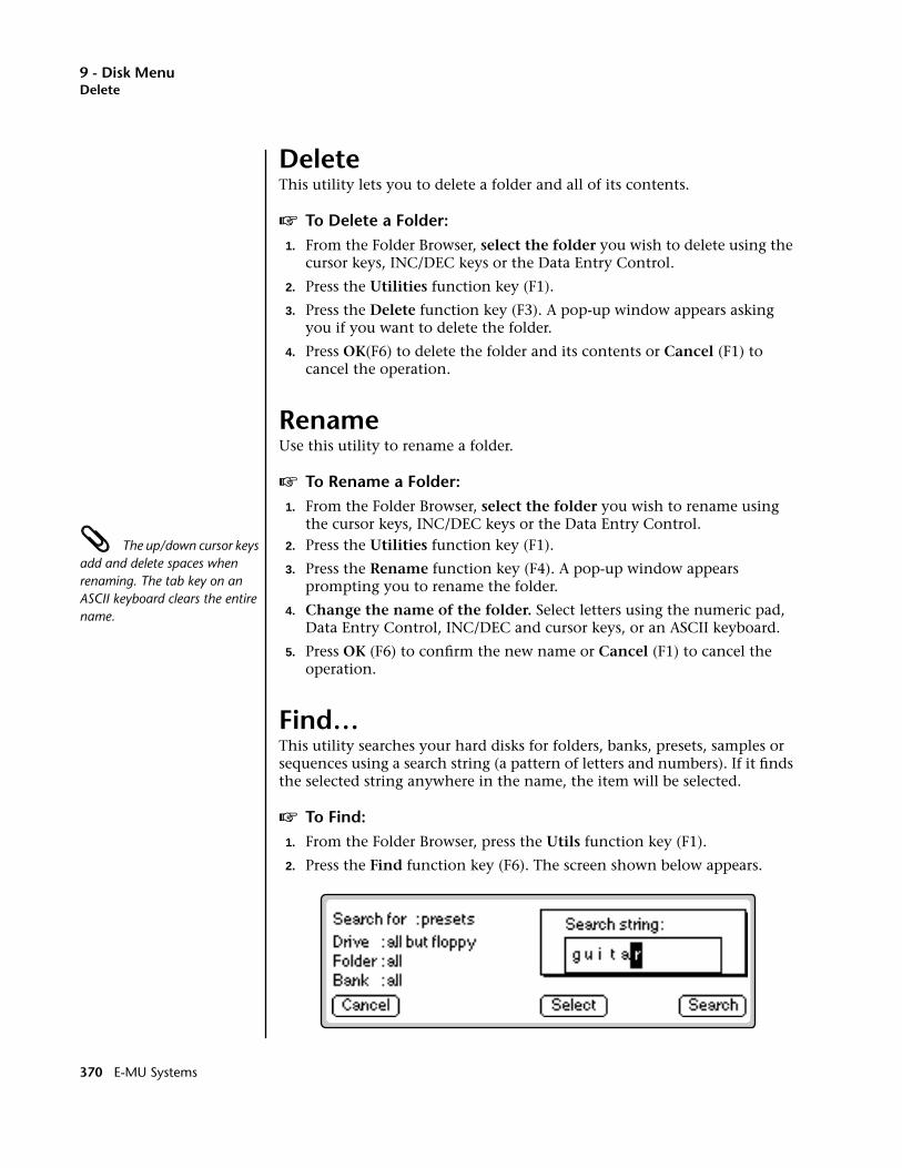
9 - Disk MenuDelete
DeleteThis utility lets you to delete a folder and all of its contents.
v To Delete a Folder:1. From the Folder Browser, select the folder you wish to delete using the
cursor keys, INC/DEC keys or the Data Entry Control.
2. Press the Utilities function key (F1).
3. Press the Delete function key (F3). A pop-up window appears asking you if you want to delete the folder.
4. Press OK(F6) to delete the folder and its contents or Cancel (F1) to cancel the operation.
RenameUse this utility to rename a folder.
v To Rename a Folder:1. From the Folder Browser, select the folder you wish to rename using
the cursor keys, INC/DEC keys or the Data Entry Control. The up/down cursor keys add and delete spaces when renaming. The tab key on an ASCII keyboard clears the entire name.
2. Press the Utilities function key (F1).
3. Press the Rename function key (F4). A pop-up window appears prompting you to rename the folder.
4. Change the name of the folder. Select letters using the numeric pad, Data Entry Control, INC/DEC and cursor keys, or an ASCII keyboard.
5. Press OK (F6) to confirm the new name or Cancel (F1) to cancel the operation.
Find…This utility searches your hard disks for folders, banks, presets, samples or sequences using a search string (a pattern of letters and numbers). If it finds the selected string anywhere in the name, the item will be selected.
v To Find:1. From the Folder Browser, press the Utils function key (F1).
2. Press the Find function key (F6). The screen shown below appears.
370 E-MU Systems
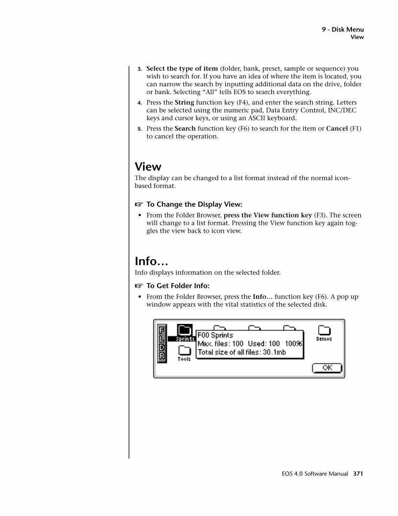
9 - Disk MenuView
3. Select the type of item (folder, bank, preset, sample or sequence) you wish to search for. If you have an idea of where the item is located, you can narrow the search by inputting additional data on the drive, folder or bank. Selecting “All” tells EOS to search everything.
4. Press the String function key (F4), and enter the search string. Letters can be selected using the numeric pad, Data Entry Control, INC/DEC keys and cursor keys, or using an ASCII keyboard.
5. Press the Search function key (F6) to search for the item or Cancel (F1) to cancel the operation.
ViewThe display can be changed to a list format instead of the normal icon-based format.
v To Change the Display View:• From the Folder Browser, press the View function key (F3). The screen
will change to a list format. Pressing the View function key again tog-gles the view back to icon view.
Info…Info displays information on the selected folder.
v To Get Folder Info:• From the Folder Browser, press the Info… function key (F6). A pop up
window appears with the vital statistics of the selected disk.
EOS 4.0 Software Manual 371

9 - Disk MenuBank Utilities
Bank
The Bank is a set of up to 1000 presets which can be loaded into and saved to disk from internal memory (RAM). When you save to disk, that collection of presets, samples and sequences is a bank. Banks can be constructed as large as the memory in your Emulator will allow (64 MB or 128 MB).
Bank UtilitiesThe Bank Utilities menu contains several additional functions. Pressing the Utils function key (F1) from the bank browser enables a second row of function keys.
Delete: Allows you to delete an unwanted bank.
Name: Allows you to name or rename the selected bank.
Find: Allows you to search the disk for a particular bank.
DeleteThis utility allows you to delete an entire bank.
v To Delete a Bank:1. From the Bank Browser, select the bank you wish to delete using the
cursor keys, INC/DEC keys or the Data Entry Control.
2. Press the Utilities function key (F1).
3. Press the Delete function key (F3). A pop-up window appears asking you if you want to delete the bank.
4. Press OK (F6) to delete the bank or Cancel (F1) to cancel the operation.
372 E-MU Systems
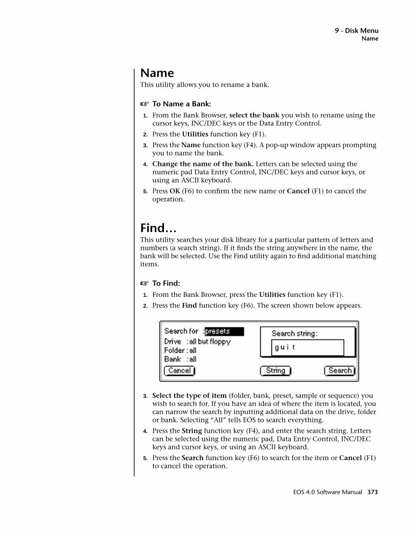
9 - Disk MenuName
NameThis utility allows you to rename a bank.
v To Name a Bank:1. From the Bank Browser, select the bank you wish to rename using the
cursor keys, INC/DEC keys or the Data Entry Control.
2. Press the Utilities function key (F1).
3. Press the Name function key (F4). A pop-up window appears prompting you to name the bank.
4. Change the name of the bank. Letters can be selected using the numeric pad Data Entry Control, INC/DEC keys and cursor keys, or using an ASCII keyboard.
5. Press OK (F6) to confirm the new name or Cancel (F1) to cancel the operation.
Find…This utility searches your disk library for a particular pattern of letters and numbers (a search string). If it finds the string anywhere in the name, the bank will be selected. Use the Find utility again to find additional matching items.
v To Find:1. From the Bank Browser, press the Utilities function key (F1).
2. Press the Find function key (F6). The screen shown below appears.
3. Select the type of item (folder, bank, preset, sample or sequence) you wish to search for. If you have an idea of where the item is located, you can narrow the search by inputting additional data on the drive, folder or bank. Selecting “All” tells EOS to search everything.
4. Press the String function key (F4), and enter the search string. Letters can be selected using the numeric pad, Data Entry Control, INC/DEC keys and cursor keys, or using an ASCII keyboard.
5. Press the Search function key (F6) to search for the item or Cancel (F1) to cancel the operation.
EOS 4.0 Software Manual 373
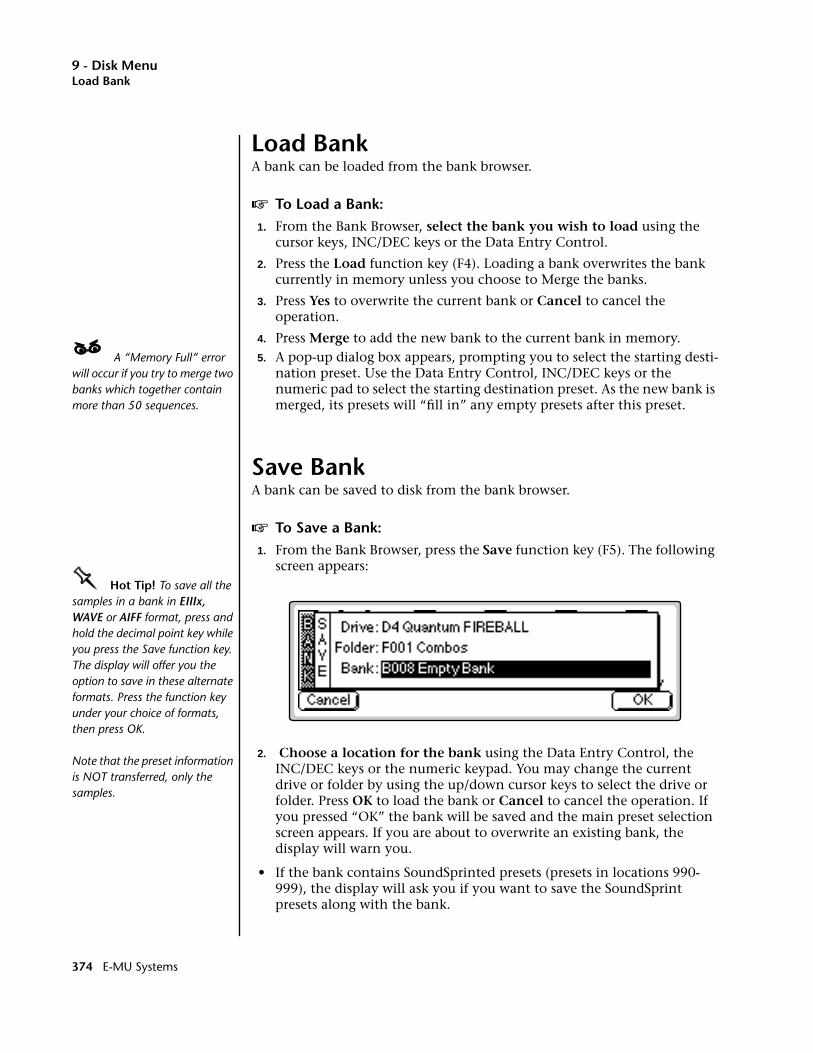
9 - Disk MenuLoad Bank
Load BankA bank can be loaded from the bank browser.
v To Load a Bank:1. From the Bank Browser, select the bank you wish to load using the
cursor keys, INC/DEC keys or the Data Entry Control.
2. Press the Load function key (F4). Loading a bank overwrites the bank currently in memory unless you choose to Merge the banks.
3. Press Yes to overwrite the current bank or Cancel to cancel the operation.
4. Press Merge to add the new bank to the current bank in memory.____ A “Memory Full” error will occur if you try to merge two banks which together contain more than 50 sequences.
5. A pop-up dialog box appears, prompting you to select the starting desti-nation preset. Use the Data Entry Control, INC/DEC keys or the numeric pad to select the starting destination preset. As the new bank is merged, its presets will “fill in” any empty presets after this preset.
Save BankA bank can be saved to disk from the bank browser.
v To Save a Bank:1. From the Bank Browser, press the Save function key (F5). The following
screen appears:OOOO Hot Tip! To save all the samples in a bank in EIIIx, WAVE or AIFF format, press and hold the decimal point key while you press the Save function key. The display will offer you the option to save in these alternate formats. Press the function key under your choice of formats, then press OK.
Note that the preset information is NOT transferred, only the samples.
2. Choose a location for the bank using the Data Entry Control, the INC/DEC keys or the numeric keypad. You may change the current drive or folder by using the up/down cursor keys to select the drive or folder. Press OK to load the bank or Cancel to cancel the operation. If you pressed “OK” the bank will be saved and the main preset selection screen appears. If you are about to overwrite an existing bank, the display will warn you.
• If the bank contains SoundSprinted presets (presets in locations 990-999), the display will ask you if you want to save the SoundSprint presets along with the bank.
374 E-MU Systems
9 - Disk MenuView
ViewThe display can be changed to a list format instead of the normal icon-based format.
v To Change the Display View:1. From the Bank Browser, press the View function key (F3). The screen
will change to a list format.
2. Pressing the View function key again toggles the view back to icon view.
Info…Information on the selected bank can be displayed.
v To Get Bank Info:1. From the Bank Browser, press the Info… function key (F6). A pop up
window appears with the vital statistics of the selected bank.
2. Press OK to return to the bank browser.
EOS 4.0 Software Manual 375
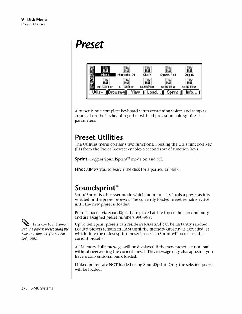
9 - Disk MenuPreset Utilities
Preset
A preset is one complete keyboard setup containing voices and samples arranged on the keyboard together with all programmable synthesizer parameters.
Preset UtilitiesThe Utilities menu contains two functions. Pressing the Utils function key (F1) from the Preset Browser enables a second row of function keys.
Sprint: Toggles SoundSprint™ mode on and off.
Find: Allows you to search the disk for a particular bank.
Soundsprint™
SoundSprint is a browser mode which automatically loads a preset as it is selected in the preset browser. The currently loaded preset remains active until the new preset is loaded.
Presets loaded via SoundSprint are placed at the top of the bank memory and are assigned preset numbers 990-999.
Links can be subsumed into the parent preset using the Subsume function (Preset Edit, Link, Utils).
Up to ten Sprint presets can reside in RAM and can be instantly selected. Loaded presets remain in RAM until the memory capacity is exceeded, at which time the oldest sprint preset is erased. (Sprint will not erase the current preset.)
A “Memory Full” message will be displayed if the new preset cannot load without overwriting the current preset. This message may also appear if you have a conventional bank loaded.
Linked presets are NOT loaded using SoundSprint. Only the selected preset will be loaded.
376 E-MU Systems
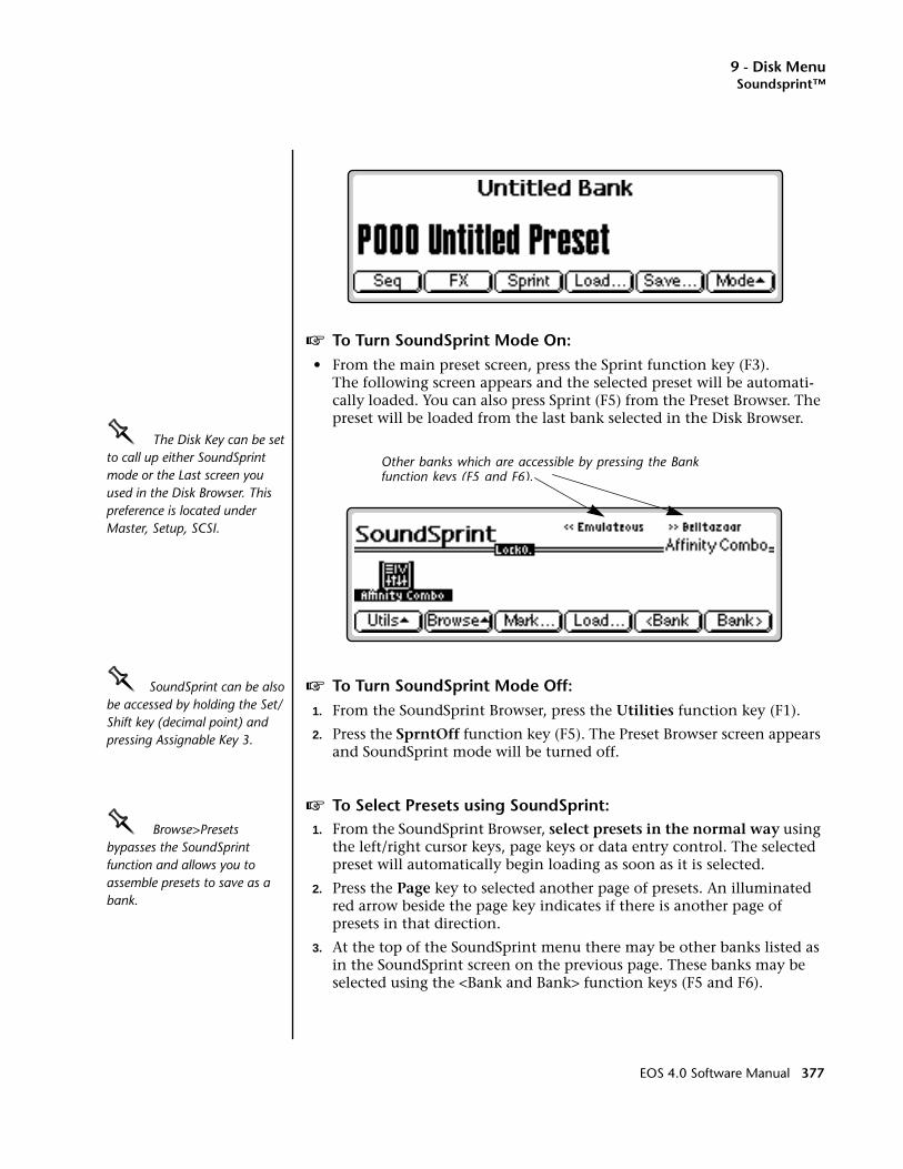
9 - Disk MenuSoundsprint™
v To Turn SoundSprint Mode On:• From the main preset screen, press the Sprint function key (F3).
The following screen appears and the selected preset will be automati-cally loaded. You can also press Sprint (F5) from the Preset Browser. The preset will be loaded from the last bank selected in the Disk Browser.
OOOO The Disk Key can be set to call up either SoundSprint mode or the Last screen you used in the Disk Browser. This preference is located under Master, Setup, SCSI.
OOOO SoundSprint can be also be accessed by holding the Set/Shift key (decimal point) and pressing Assignable Key 3.
v To Turn SoundSprint Mode Off:1. From the SoundSprint Browser, press the Utilities function key (F1).
2. Press the SprntOff function key (F5). The Preset Browser screen appears and SoundSprint mode will be turned off.
v To Select Presets using SoundSprint:OOOO Browse>Presets bypasses the SoundSprint function and allows you to assemble presets to save as a bank.
1. From the SoundSprint Browser, select presets in the normal way using the left/right cursor keys, page keys or data entry control. The selected preset will automatically begin loading as soon as it is selected.
2. Press the Page key to selected another page of presets. An illuminated red arrow beside the page key indicates if there is another page of presets in that direction.
3. At the top of the SoundSprint menu there may be other banks listed as in the SoundSprint screen on the previous page. These banks may be selected using the <Bank and Bank> function keys (F5 and F6).
Other banks which are accessible by pressing the Bankfunction keys (F5 and F6).
EOS 4.0 Software Manual 377
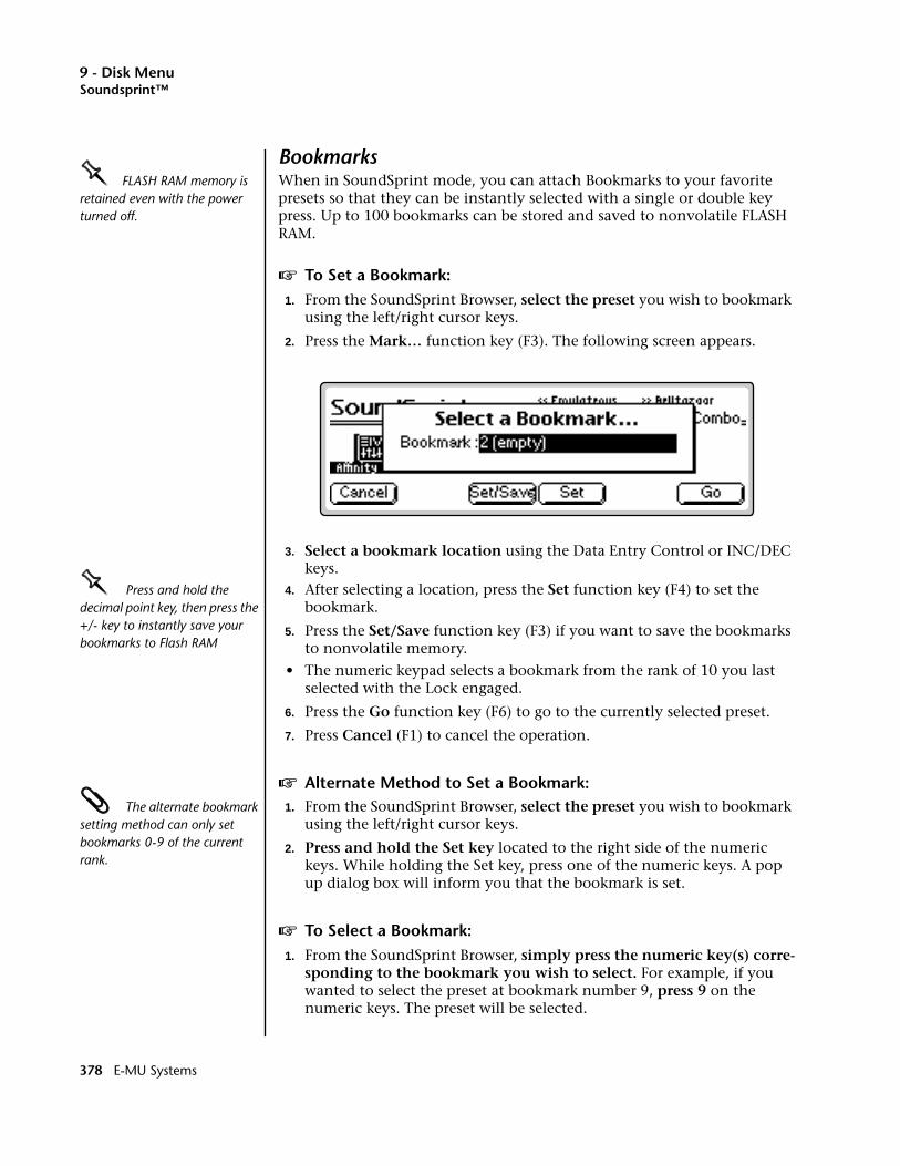
9 - Disk MenuSoundsprint™
BookmarksOOOO FLASH RAM memory is retained even with the power turned off.
When in SoundSprint mode, you can attach Bookmarks to your favorite presets so that they can be instantly selected with a single or double key press. Up to 100 bookmarks can be stored and saved to nonvolatile FLASH RAM.
v To Set a Bookmark:1. From the SoundSprint Browser, select the preset you wish to bookmark
using the left/right cursor keys.
2. Press the Mark… function key (F3). The following screen appears.
3. Select a bookmark location using the Data Entry Control or INC/DEC keys.
OOOO Press and hold the decimal point key, then press the +/- key to instantly save your bookmarks to Flash RAM
4. After selecting a location, press the Set function key (F4) to set the bookmark.
5. Press the Set/Save function key (F3) if you want to save the bookmarks to nonvolatile memory.
• The numeric keypad selects a bookmark from the rank of 10 you last selected with the Lock engaged.
6. Press the Go function key (F6) to go to the currently selected preset.
7. Press Cancel (F1) to cancel the operation.
v Alternate Method to Set a Bookmark: The alternate bookmark setting method can only set bookmarks 0-9 of the current rank.
1. From the SoundSprint Browser, select the preset you wish to bookmark using the left/right cursor keys.
2. Press and hold the Set key located to the right side of the numeric keys. While holding the Set key, press one of the numeric keys. A pop up dialog box will inform you that the bookmark is set.
v To Select a Bookmark:1. From the SoundSprint Browser, simply press the numeric key(s) corre-
sponding to the bookmark you wish to select. For example, if you wanted to select the preset at bookmark number 9, press 9 on the numeric keys. The preset will be selected.
378 E-MU Systems
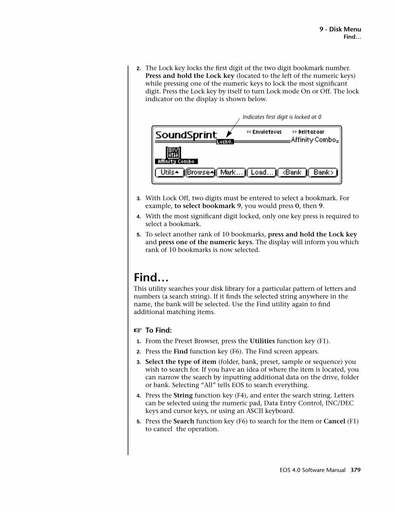
9 - Disk MenuFind…
2. The Lock key locks the first digit of the two digit bookmark number. Press and hold the Lock key (located to the left of the numeric keys) while pressing one of the numeric keys to lock the most significant digit. Press the Lock key by itself to turn Lock mode On or Off. The lock indicator on the display is shown below.
3. With Lock Off, two digits must be entered to select a bookmark. For example, to select bookmark 9, you would press 0, then 9.
4. With the most significant digit locked, only one key press is required to select a bookmark.
5. To select another rank of 10 bookmarks, press and hold the Lock key and press one of the numeric keys. The display will inform you which rank of 10 bookmarks is now selected.
Find…This utility searches your disk library for a particular pattern of letters and numbers (a search string). If it finds the selected string anywhere in the name, the bank will be selected. Use the Find utility again to find additional matching items.
v To Find:1. From the Preset Browser, press the Utilities function key (F1).
2. Press the Find function key (F6). The Find screen appears.
3. Select the type of item (folder, bank, preset, sample or sequence) you wish to search for. If you have an idea of where the item is located, you can narrow the search by inputting additional data on the drive, folder or bank. Selecting “All” tells EOS to search everything.
4. Press the String function key (F4), and enter the search string. Letters can be selected using the numeric pad, Data Entry Control, INC/DEC keys and cursor keys, or using an ASCII keyboard.
5. Press the Search function key (F6) to search for the item or Cancel (F1) to cancel the operation.
Indicates first digit is locked at 0
EOS 4.0 Software Manual 379
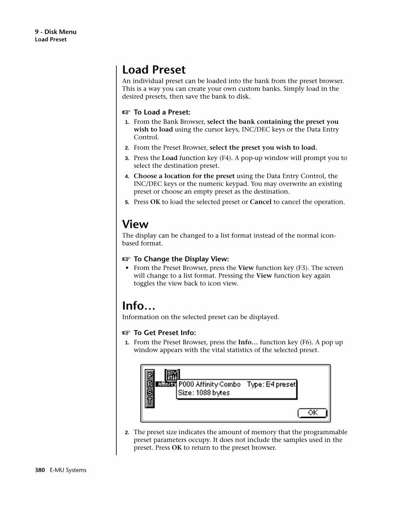
9 - Disk MenuLoad Preset
Load PresetAn individual preset can be loaded into the bank from the preset browser. This is a way you can create your own custom banks. Simply load in the desired presets, then save the bank to disk.
v To Load a Preset:1. From the Bank Browser, select the bank containing the preset you
wish to load using the cursor keys, INC/DEC keys or the Data Entry Control.
2. From the Preset Browser, select the preset you wish to load.
3. Press the Load function key (F4). A pop-up window will prompt you to select the destination preset.
4. Choose a location for the preset using the Data Entry Control, the INC/DEC keys or the numeric keypad. You may overwrite an existing preset or choose an empty preset as the destination.
5. Press OK to load the selected preset or Cancel to cancel the operation.
ViewThe display can be changed to a list format instead of the normal icon-based format.
v To Change the Display View:• From the Preset Browser, press the View function key (F3). The screen
will change to a list format. Pressing the View function key again toggles the view back to icon view.
Info…Information on the selected preset can be displayed.
v To Get Preset Info:1. From the Preset Browser, press the Info… function key (F6). A pop up
window appears with the vital statistics of the selected preset.
2. The preset size indicates the amount of memory that the programmable preset parameters occupy. It does not include the samples used in the preset. Press OK to return to the preset browser.
380 E-MU Systems
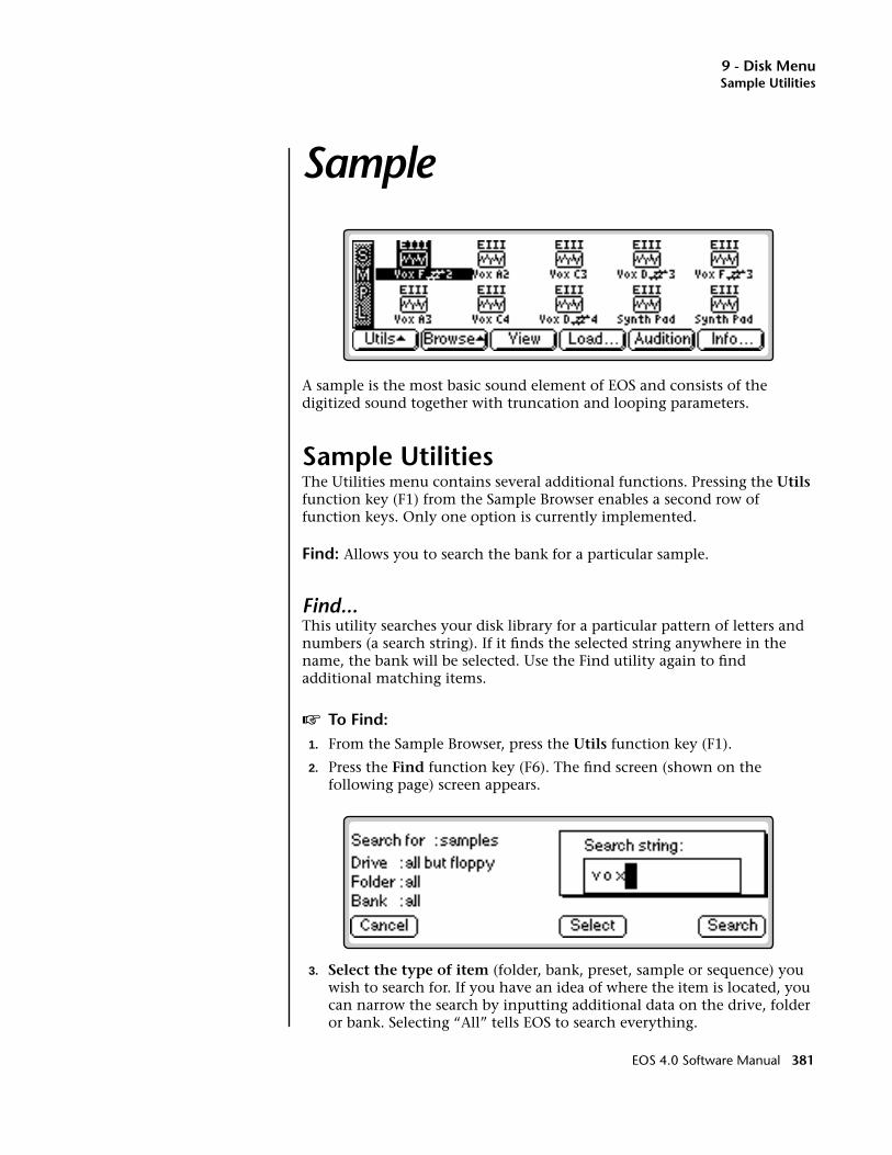
9 - Disk MenuSample Utilities
Sample
A sample is the most basic sound element of EOS and consists of the digitized sound together with truncation and looping parameters.
Sample UtilitiesThe Utilities menu contains several additional functions. Pressing the Utils function key (F1) from the Sample Browser enables a second row of function keys. Only one option is currently implemented.
Find: Allows you to search the bank for a particular sample.
Find...This utility searches your disk library for a particular pattern of letters and numbers (a search string). If it finds the selected string anywhere in the name, the bank will be selected. Use the Find utility again to find additional matching items.
v To Find:1. From the Sample Browser, press the Utils function key (F1).
2. Press the Find function key (F6). The find screen (shown on the following page) screen appears.
3. Select the type of item (folder, bank, preset, sample or sequence) you wish to search for. If you have an idea of where the item is located, you can narrow the search by inputting additional data on the drive, folder or bank. Selecting “All” tells EOS to search everything.
EOS 4.0 Software Manual 381
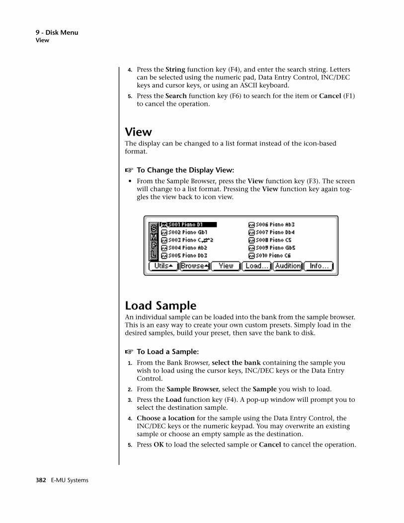
9 - Disk MenuView
4. Press the String function key (F4), and enter the search string. Letters can be selected using the numeric pad, Data Entry Control, INC/DEC keys and cursor keys, or using an ASCII keyboard.
5. Press the Search function key (F6) to search for the item or Cancel (F1) to cancel the operation.
ViewThe display can be changed to a list format instead of the icon-based format.
v To Change the Display View:• From the Sample Browser, press the View function key (F3). The screen
will change to a list format. Pressing the View function key again tog-gles the view back to icon view.
Load SampleAn individual sample can be loaded into the bank from the sample browser. This is an easy way to create your own custom presets. Simply load in the desired samples, build your preset, then save the bank to disk.
v To Load a Sample:1. From the Bank Browser, select the bank containing the sample you
wish to load using the cursor keys, INC/DEC keys or the Data Entry Control.
2. From the Sample Browser, select the Sample you wish to load.
3. Press the Load function key (F4). A pop-up window will prompt you to select the destination sample.
4. Choose a location for the sample using the Data Entry Control, the INC/DEC keys or the numeric keypad. You may overwrite an existing sample or choose an empty sample as the destination.
5. Press OK to load the selected sample or Cancel to cancel the operation.
382 E-MU Systems
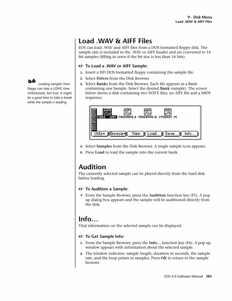
9 - Disk MenuLoad .WAV & AIFF Files
Load .WAV & AIFF FilesEOS can load .WAV and AIFF files from a DOS formatted floppy disk. The sample rate is included in the .WAV or AIFF header and are converted to 16 bit samples (filling in zeros if the bit size is less than 16 bits).
v To Load a .WAV or AIFF Sample:1. Insert a HD DOS formatted floppy containing the sample file.
2. Select Drives from the Disk Browser.____ Loading samples from floppy can take a LONG time. Unfortunate, but true. It might be a good time to take a break while the sample is loading.
3. Select Banks from the Disk Browser. Each file appears as a Bank containing one Sample. Select the desired Bank (sample). The screen below shows a disk containing two WAVE files, an AIFF file and a MIDI sequence.
4. Select Samples from the Disk Browser. A single sample icon appears.
5. Press Load to load the sample into the current bank.
AuditionThe currently selected sample can be played directly from the hard disk before loading.
v To Audition a Sample:• From the Sample Browser, press the Audition function key (F5). A pop
up dialog box appears and the sample will be auditioned directly from the disk.
Info…Vital information on the selected sample can be displayed.
v To Get Sample Info:1. From the Sample Browser, press the Info… function key (F6). A pop up
window appears with information about the selected sample.
2. The window indicates: sample length, duration in seconds, the sample rate, and the loop points in samples. Press OK to return to the sample browser.
EOS 4.0 Software Manual 383

9 - Disk MenuSequence Utility
Sequence
Up to 50 sequences can be loaded into a bank or saved to disk as part of a bank. When you Save to disk, you are saving all presets, samples and sequences currently residing in RAM. Sequences do not appear in the Sequence Browser until you have saved the bank to disk.
Sequence UtilityThe Sequence Utilities menu contains only one function — Find. Pressing the Utils function key (F1) from the Sequence Browser enables a second row of function keys.
Find: Allows you to search the disk for a particular sequence.
384 E-MU Systems

9 - Disk MenuFind…
Find…This utility searches your disk library for a particular pattern of letters and numbers (a search string). If it finds the selected string anywhere in the name, the bank is selected. Use the Find utility again to find additional matching items.
v To Find:1. From the Sequence Browser, press the Utilities function key (F1).
2. Press the Find function key (F6). The screen shown below appears.
3. Select the type of item (folder, bank, preset, sample or sequence) you wish to search for. If you have an idea of where the item is located, you can narrow the search by inputting additional data on the drive, folder or bank. Selecting “All” tells EOS to search everything.
4. Press the String function key (F4), and enter the search string. Letters can be selected using the numeric pad, Data Entry Control, INC/DEC keys and cursor keys, or using an ASCII keyboard.
5. Press the Search function key (F6) to search for the item or the Cancel function key (F1) to cancel the operation.
ViewThe display can be changed to a list format instead of the icon-based format.
v To Change the Display View:• From the Sequence Browser, press the View function key (F3). The
screen will change to a list format. Pressing the View function key again toggles the view back to icon view.
Load SequenceAn individual sequence can be loaded from another bank using the sequence browser. Simply load in the desired sequences, then save the bank to disk. Sequences can be either Emulator sequences or Standard MIDI Files. If you wish to load a sequence from another bank into the current bank perform the following steps.
v To Load a Sequence from another Bank:1. From the Disk Browser, select the drive and bank containing the
sequence you wish to load using the cursor keys, INC/DEC keys or the Data Entry Control.
2. From the Sequence Browser, select the sequence you wish to load.
EOS 4.0 Software Manual 385
9 - Disk MenuInfo…
3. Press the Load function key (F4). A pop-up window will prompt you to select the destination sequence.
4. Choose a location for the sequence using the Data Entry Control, the INC/DEC keys or the numeric keypad. You may overwrite an existing sequence or choose an empty sequence as the destination. There are 50 possible sequence locations.
5. Press OK to load the selected sequence or Cancel to cancel the operation.
Info…Displays information about the selected sequence.
v To Get Sequence Info:1. From the Sequence Browser, press the Info… function key (F6). A pop
up window appears with information about the selected sequence.
2. The window indicates: sequence number, size in bytes, and type (either EIV or Standard MIDI File).
The Emulator can load and play Standard MIDI File sequences (type 0 or 1). Sequence files should conform to PC DOS format using a DOS formatted disk and using the following format for the file name: 12345678.MID (up to eight characters followed by “.MID”). It is important to note that Standard MIDI Files appear as Banks, NOT as sequences in the sequence browser.
v To Load a Standard MIDI File from Floppy Disk:1. Insert a DOS formatted floppy disk containing the Standard MIDI
Files.
2. From the Disk Browser, select the floppy drive.
3. Press Browse again and select Banks. The MIDI sequences appears as banks.
4. Press the Load function key (F4). A pop up dialog box appears warning you that loading will destroy the resident bank.
5. Press the Merge key (F4). The selected sequence will be merged into the current bank, and will be placed in the first empty sequence location.
6. Press OK to load the selected sequence or Cancel to cancel the operation.
Important Information for Loading Standard MIDI Files• Use PC DOS formatted diskettes to load from floppy. Disks can be for-
matted on either the Mac or PC.
• To be readable by EOS, the file MUST have 0-8 characters, then a period, then “MID.”
386 E-MU Systems

10 - Appendix
10Appendix
EOS 4.0 Software Manual 387

10 - Appendix
388 E-MU Systems

10 - AppendixWhy Use SCSI?
SCSI
SCSI (pronounced skuzzy) stands for Small Computer System Interface. SCSI is an industry standard hardware and software specification that allows high-speed data transfers between different pieces of equipment. SCSI devices can include hard disks, tape drives, optical disks and other types of digital equipment.
Why Use SCSI?• SCSI is fast! SCSI is a parallel interface which transmits eight bits of
information at a time at high speed over the SCSI cable. MIDI, in com-parison, is a serial interface which can only send one bit of information at a time over its line.
• Compatibility: Since SCSI is an industry standard, equipment from many different manufacturers can be linked to work together.
• Expandability: Up to eight SCSI devices can be linked together (the Emulator counts as one SCSI device on the chain).
The SCSI BusYou may have noticed that the rear panel of most external storage devices have two SCSI connectors. This is because SCSI devices are connected together in a chain arrangement. The wires that connect the different pieces of equipment are called the SCSI bus.
ID NumbersOOOO IDE Drives: Ultra Series Emulators can use an internal IDE hard disk. IDE drives have several advantages such as low cost, high capacity, low noise and they don’t use up a precious SCSI ID number.
• Order IDE installation kit number 6303. This kit includes everything necessary except the IDE drive.
Each device on the SCSI bus has its own ID number so that it can distin-guish its data from data meant for another device. For example, if data is being saved to a device with ID-2, all the other devices on the SCSI bus will ignore that data. If two devices have the same ID number, the system will not work. Each device must have its own unique ID number.
The SCSI ID number of a Macintosh computer is fixed at ID-7 and cannot be changed. The SCSI ID numbers of most other devices can be changed.
Many SCSI devices have hardware defined ID numbers, which means that they have a switch on the front or the back of the unit which allows the ID number to be easily identified and changed.
EOS 4.0 Software Manual 389
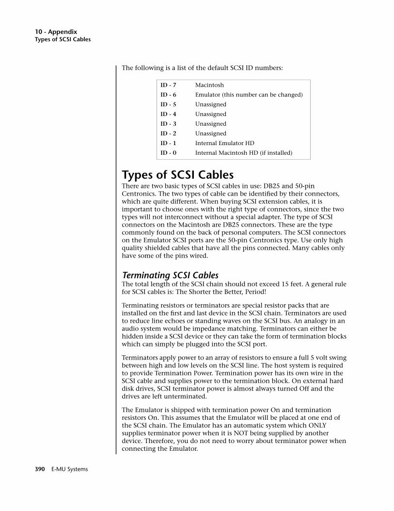
10 - AppendixTypes of SCSI Cables
The following is a list of the default SCSI ID numbers:
Types of SCSI CablesThere are two basic types of SCSI cables in use: DB25 and 50-pin Centronics. The two types of cable can be identified by their connectors, which are quite different. When buying SCSI extension cables, it is important to choose ones with the right type of connectors, since the two types will not interconnect without a special adapter. The type of SCSI connectors on the Macintosh are DB25 connectors. These are the type commonly found on the back of personal computers. The SCSI connectors on the Emulator SCSI ports are the 50-pin Centronics type. Use only high quality shielded cables that have all the pins connected. Many cables only have some of the pins wired.
Terminating SCSI CablesThe total length of the SCSI chain should not exceed 15 feet. A general rule for SCSI cables is: The Shorter the Better, Period!
Terminating resistors or terminators are special resistor packs that are installed on the first and last device in the SCSI chain. Terminators are used to reduce line echoes or standing waves on the SCSI bus. An analogy in an audio system would be impedance matching. Terminators can either be hidden inside a SCSI device or they can take the form of termination blocks which can simply be plugged into the SCSI port.
Terminators apply power to an array of resistors to ensure a full 5 volt swing between high and low levels on the SCSI line. The host system is required to provide Termination Power. Termination power has its own wire in the SCSI cable and supplies power to the termination block. On external hard disk drives, SCSI terminator power is almost always turned Off and the drives are left unterminated.
The Emulator is shipped with termination power On and termination resistors On. This assumes that the Emulator will be placed at one end of the SCSI chain. The Emulator has an automatic system which ONLY supplies terminator power when it is NOT being supplied by another device. Therefore, you do not need to worry about terminator power when connecting the Emulator.
ID - 7 Macintosh
ID - 6 Emulator (this number can be changed)
ID - 5 Unassigned
ID - 4 Unassigned
ID - 3 Unassigned
ID - 2 Unassigned
ID - 1 Internal Emulator HD
ID - 0 Internal Macintosh HD (if installed)
390 E-MU Systems
10 - AppendixSCSI Problems
The termination resistors in the Emulator can be turned On or Off under software control. This function is located under Miscellaneous in the Master menu. If you have an Emulator connected in the middle of a SCSI chain (which can be done using a special SCSI “Y” cable), you would want to turn SCSI termination Off. Normally, the Emulator will be at one end of the chain and will have termination On.
The more devices you have connected to SCSI and the longer your cables are, the more it becomes important to have the cables properly terminated.
SCSI ProblemsIn diagnosing SCSI problems the first rule is: Don't panic, experiment! If you have several SCSI devices hooked up, first check the SCSI ID numbers, then try disconnecting one of the devices and maybe change the order of the units on the line. There are quite a number of different SCSI drives on the market each with slightly different electrical characteristics. The following checklist may help you find the solution to your unique SCSI setup.
1. Make sure the drive is mounted. Mount the drives using the Mount Drive utility (Disk, Utilities).
2. Check the SCSI ID numbers. No two numbers on the bus can be the same.
3. Read the documentation again. Learn all you can about your peripheral devices. The answer to your problem may be right in front of you.
4. Play with the order in which devices are powered up. Normally the “Big Bang” method works best (turn everything on at once), but another order may work better in your unique system. Experiment!
5. Always suspect the cable when something doesn't work on the SCSI bus. Remember: The shorter the cables are, the better.
6. Simplify the situation. Disconnect one or more drives until you get the system to work.
7. Are the ends of the SCSI bus terminated?
8. If all else fails, call us. We're here if you need us at 831-438-1921. Telephone support hours are 9:00 to 5:00 PST, Monday through Friday.
EOS 4.0 Software Manual 391

10 - AppendixSample Transfers Via SMDI
Sample Transfers Via SMDIOOOO You can check the “Memory Statistics” screen when downloading samples via SMDI to keep track of how much RAM you have left.
The Emulator can now be connected to the SCSI along with another Emulator, an ESI-32, or a personal computer. Multiple “Master” devices on the SCSI bus is not normally allowed by the standard SCSI protocol but is possible because of Emulator's advanced SCSI and SMDI (or SCSI Musical Data Interchange) implementation. Sample data can now be exchanged over the SCSI bus in a way similar to the MIDI Sample Dump Standard, except MUCH faster.
The computer should normally be positioned at one end of the chain and the Emulator at the other. The SCSI chain is properly terminated at each end by the computer and the Emulator. Devices in the middle of the chain should not have termination resistors installed.
• PC Compatibles - The Emulator has been tested with IBM PC compati-ble computers using the Adaptec model 1542C SCSI option card. Sound files can be transferred between a PC computer and the Emulator using Sound Forge™, Recycle™ or other sample editing software.
____ When using Alchemy, you must add one to the sample number you want transferred.
• Macintosh - Sound files can be transferred between a Macintosh com-puter and the Emulator using Recycle™, Transfer Station™, Alchemy™ or other digital sample editing software. The Emulator is able to access approved Macintosh internal CD-ROM drives with CD-ROMs contain-ing EOS compatible files.
____ You cannot transfer to or from sample 000 (the clipboard).
• The Emulator is strictly a “Slave Device” when using SMDI, meaning that it CANNOT initiate SMDI transfers. This should not normally present a problem, since a computer based editor will always have the capability to transmit and request a transfer.
Caution: A sample transferred into the Emulator will be automatically placed across the entire keyboard, overwriting the current preset's sample placement. Create a new empty preset before downloading via SMDI to avoid trashing the current preset.
Besides the raw sample data, additional information about the sample is included in a SMDI file including:
• Sample name and number (samples 1-999)
• Multichannel/Stereo/Mono status
• Sample length plus one set of loop begin/end points
• Sample rate, pitch and bit resolution
• Sample key placement (an E-mu extension to SMDI)
392 E-MU Systems
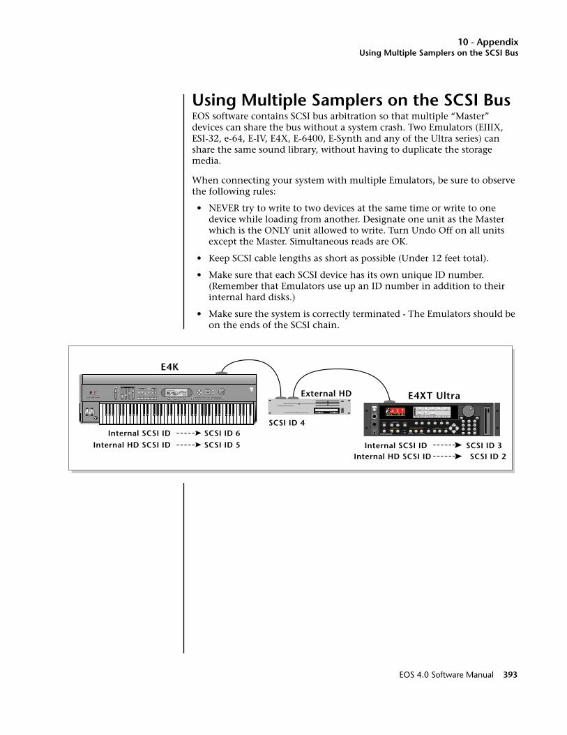
10 - AppendixUsing Multiple Samplers on the SCSI Bus
Using Multiple Samplers on the SCSI BusEOS software contains SCSI bus arbitration so that multiple “Master” devices can share the bus without a system crash. Two Emulators (EIIIX, ESI-32, e-64, E-IV, E4X, E-6400, E-Synth and any of the Ultra series) can share the same sound library, without having to duplicate the storage media.
When connecting your system with multiple Emulators, be sure to observe the following rules:
• NEVER try to write to two devices at the same time or write to one device while loading from another. Designate one unit as the Master which is the ONLY unit allowed to write. Turn Undo Off on all units except the Master. Simultaneous reads are OK.
• Keep SCSI cable lengths as short as possible (Under 12 feet total).
• Make sure that each SCSI device has its own unique ID number. (Remember that Emulators use up an ID number in addition to their internal hard disks.)
• Make sure the system is correctly terminated - The Emulators should be on the ends of the SCSI chain.
E4K
E4XT UltraExternal HD
Internal SCSI IDSCSI ID 4
Internal SCSI ID SCSI ID 3
SCSI ID 6Internal HD SCSI ID SCSI ID 5
Internal HD SCSI ID SCSI ID 2
EMULATOR
P R E S E T
S A M P L E
S E Q U E N C E R
P A G E
L E V E L
P R E S E T S E L E C T
R E A L T I M E C O N T R O L L E R SA S S I G N A B L E K E Y S
E N T E RE X I T
R E T U R N
0 .987654321
EOS 4.0 Software Manual 393
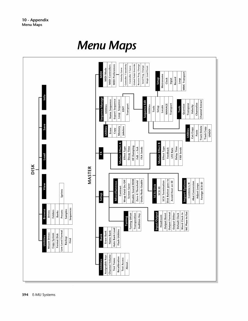
10 - AppendixMenu Maps
Menu Maps
Menu Maps
Bro
wse
Dri
ves
Fold
ers
Ban
ks
Pre
sets
Sam
ple
s
Seq
uen
ces
DIS
K
Uti
liti
esM
ou
nt
Dri
ves
Co
py
Syst
em
Form
at D
isk
Low
Lev
el F
orm
at
Bac
kup
Fin
d
Info
Save
Load
Vie
w
Spri
nts
Ban
kEr
ase
Ban
k
Nam
e B
ank
Au
to B
ank
Load
Flas
h U
tili
ties
MA
STER
Uti
liti
esA
ssig
nab
le K
eys
Ch
ann
el V
olu
me
Tes
t T
on
es
Rec
alib
rati
on
Tes
t A
cces
s
Ab
ou
t…
Vel
oci
ty C
urv
e
Co
ntr
olle
r 7
Sen
siti
vity
Co
ntr
oll
er 7
Cu
rve
Glo
bal
Ped
al O
verr
ide
Rec
eive
Pro
g.
Ch
ang
e
Sen
d P
rog
. C
han
ge
Mag
ic L
oad
Pre
set
MID
IM
IDI
Mo
de
MID
I C
on
tro
ller
s
MID
I P
refe
ren
ces
Seq
uen
ce M
anag
e
Uti
liti
es
Nam
e Se
qu
ence
Exp
ort
Seq
uen
ce
Loo
p
Seq
uen
ce
EDIT
Tra
nsp
ort
Seq
uen
ce E
dit
Uti
liti
es
To
ols
Setu
p
Loca
te
MA
NA
GE
Tra
nsp
ort
Uti
litie
s
Eras
e
Co
py
Mem
ory
Juke
bo
x
Uti
litie
s
Cu
t/C
op
y
Pas
te
Tra
ck D
elet
e
Tra
ck C
op
y
UN
DO
!
Tool
s
Qu
anti
ze
Tra
nsp
ose
Vel
oci
ty
Ch
ann
eliz
e
Ch
ann
el E
xtra
ct
Setu
p
Met
ron
om
e
Clo
ck
Inp
ut
Rec
ord
Loo
p
MM
C T
ran
spo
rt
Mis
cell
aneo
us
Co
ntr
ast
Wra
p F
ield
On
/Off
Scre
en S
aver
Dis
able
So
un
d R
OM
Zer
o-X
Th
resh
old
Un
do
/Red
o E
nab
le
SCSI
/Dis
kSC
SI I
D
SCSI
Ter
min
atio
n
Dis
k B
utt
on
go
es t
o
Avo
id H
ost
on
ID
Inp
ut/O
utp
utH
ead
roo
m
Ou
tpu
t B
oo
st
Ou
tpu
t Fo
rmat
Ou
tpu
t D
ith
er
Def
ault
Clo
ck
Wo
rd C
lock
In
WC
Pha
se In
/Out
Mas
ter
Effe
ct A
Effe
ct T
ype
Dec
ay T
ime
HF
Dam
pin
g
FxB
->
FxA
FXA
Sen
ds
Mas
ter
Effe
ct B
Effe
ct T
ype
Feed
bac
k
LFO
Rat
e
Del
ay T
ime
FXB
Sen
ds
Tu
nin
gT
un
ing
Off
set
Tra
nsp
osi
tio
n
Au
dit
ion
Key
Imp
ort
Op
tio
ns
Co
mb
ine
L/R
Aka
i C
on
vers
ion
Ad
just
Lo
op
s
Fore
ign
SC
SI I
D
Setu
pFX
394 E-MU Systems
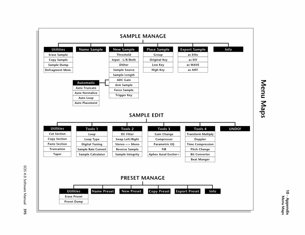
EOS 4.0 Softw
are Manual 395
10 - Ap
pen
dix
Men
u Map
s
Men
u Map
s
UNDO!
Info
SAMPLE EDIT
UtilitiesCut Section
Copy Section
Paste Section
Truncation
Taper
Tools 4Transform Multiply
Doppler
Time Compression
Pitch Change
Bit Converter
Beat Munger
Tools 3Gain Change
Compressor
Parametric EQ
FIR
Aphex Aural Exciter™
Tools 1Loop
Loop Type
Digital Tuning
Sample Rate Convert
Sample Calculator
Tools 2DC Filter
Swap Left/Right
Stereo <-> Mono
Reverse Sample
Sample Integrity
AutomaticAuto Truncate
Auto Normalize
Auto Loop
Auto Placement
SAMPLE MANAGE
UtilitiesErase Sample
Copy Sample
Sample Dump
Defragment Mem.
Place SampleGroup
Original Key
Low Key
High Key
Name Sample Export Sampleas EIIIx
as EIV
as WAVE
as AIFF
New SampleThreshold
Input - L/R/Both
Dither
Sample Source
Sample Length
ADC Gain
Arm Sample
Force Sample
Trigger Key
UtilitiesErase Preset
Preset Dump
PRESET MANAGE
InfoCopy PresetNew PresetName Preset Export Preset
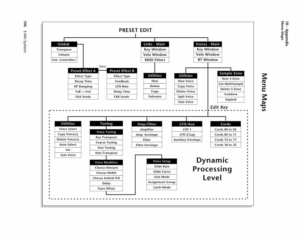
396 E-M
10 - Ap
pen
dix
Men
u Map
s
Men
u Map
s
PRESET EDIT
CordsCords 00 to 05
Cords 06 to 11
Cords 12 to 17
Cords 18 to 23
Sample ZoneNew S-Zone
Get MultiSample
Delete S-Zone
Combine
Expand
ainow
ow
ow
micssingel
dit Key
U System
s
Global Transpose
Volume
Init. Controllers
Links - Main
Velo WindowMIDI Filters
LFO/AuxLFO 1
LFO 2/Lag
Auxiliary Envelope
Amp/FilterAmplifier
Amp. Envelope
Filter
Filter Envelope
UtilitiesNew Voice
Copy Voice
Delete Voice
Split Voice
Solo Voice
UtilitiesVoice Select
Copy Voice(s)
Delete Voice(s)
Auto-Select
Set
Solo Voice
Voice Modifiers
Chorus Amount
Chorus Width
Chorus Intitial ITD
Delay
Start Offset
UtilitiesNew
Delete
Copy
Subsume
Voices - MKey Wind
Velo Wind
RT Wind
Key Window
Tuning
Voice Tuning
Key Transpose
Coarse Tuning
Fine Tuning
Non-Transpose
DynaProce
Lev
E
Voice Setup
Glide Rate
Glide Curve
Solo Mode
Assignment Group
Latch Mode
Preset Effect AEffect Type
Decay Time
HF Damping
FxB -> FxA
FXA Sends
Preset Effect BEffect Type
Feedback
LFO Rate
Delay Time
FXB Sends
Next

10 - AppendixMIDI Implementation Chart
MIDI MIDI Implementation Chart
Transmitted Recognized RemarksBasicChannel
DefaultChanged
Mode DefaultMessages
NoteNumber True Voice
Velocity Note ONNote OFF
AfterTouch
KeysChannels
Pitch Bender
Control Change
ProgramChange True Number
System Exclusive
SystemCommon
:Song Pos:Song Sel:Tune
SystemReal Time
:Clock:Commands
AuxMessages
:Local On/Off:Active Sense:Reset
NoNo
11-16
32 with Channel Option
No Mode 1, 3, 4MONO, POLYOMNI, ON/OFF
Memorized
E4K/E-Synth KybdE4K/E-Synth Kybd
0-1270-127
E4K/E-Synth KybdE4K/E-Synth Kybd
YesYes
v=1-127
NoE4K/E-Synth Kybd
NoYes
E4K/E-Synth Kybd Yes
E4K/E-Synth Kybd Yes
E4K/E-Synth Kybd Yes 0-127Yes 0-127
Yes Yes * See note below
NoNoNo
NoYesNo
YesYes
YesYes
NoNoNo
NoNoNo
Notes:
Function…
Mode 1: OMNI ON, POLYMode 3: OMNI OFF, POLY
Mode 2: OMNI ON, MONOMode 4: OMNI OFF, MONO
0-31
Bank Select No Yes
64-97
All Sound Off
Reset All Controllers
No No
No Yes
All Notes Off No Yes
* SysEx: EOS contains an extensive MIDI SysEx implementation to support Editor/Librarian applications. Contact E-mu Systems for specifications (www.emu.com)
Submix Assignments: MIDI CC #79 (0=voice, 1=main, 2=sub1…8=sub7)
EOS 4.0 Software Manual 397
10 - Appendix
Notes:
398 E-MU Systems

Index
Symbols.WAV export 189.WAV files, loading 383.WAV, save bank as 374“A” effect types 97“B” effect types 98
Numerics3 way effects control 99
AADAT optical, sampling from 180ADAT Output Dither 83ADAT, optical interface 85ADC Gain 181Adjust Fractional Loops 94adjusting fractional loops 93aftertouch, mono 255AIFF export 189AIFF files, loading 383AIFF, save bank as 374Akai 4, 93Akai Conversion 93Akai sound 4Akai sound libraries 4Allpass filter 227amp, summing 263analog oscillator sound 335Aphex Aural Exciter 229Aphex, aural exciter 229Arm Sample Trigger 182arpeggiator 11, 12, 13
clock 260octave extension 11sequencing 50
Arpeggiator Direction 12Artificial Decay 197Assign Group, voice 340Assignable Keys 46, 66assignable keys 46, 66Attack Time, compressor 222Audition 383audition key 80Audition, sample 383Aural Exciter 229Auto Bank Load 72Auto bank load 42Auto Correlate 209Auto Correlation 196auto load a bank 42, 72auto voice selection 331Auto/Manual voice select 326
Automatic Digital Signal Processing 184Automatic sampling parameters 184Automatic Voice Selection 331automatic voice selection mode 276Auto-sample placement 186Auxiliary Envelope 348, 350auxiliary envelope 324Avoid Host on ID 91
BBackup 364band-pass filter 271Bandwidth, EQ 226Bank 41
erase 71bank 7, 10
about 26auto load 42, 72erasing 46, 71merging 42name 72naming 46, 72saving 44
Bank Info 375Bank Utilities 372Bank, definition 26Bank, erase 46Bank, naming 46Bank, saving 10, 44banks
loading 42basic channel, MIDI 103Beat Munger 237Beat, munging 237Bit Converter 236BNC 85Bookmarks 378bookmarks, definition & use 25boost, output 82Browse 358Browser 38bus, effects 118button
assignment, disk 92thumby 255
bypass, effects 125
Ccables, SCSI 390calculator, sample 213Center Frequency, EQ 226Change Preset, in split mode 15Changing, bit resolution of a
sample 236channel expander card, MIDI 107Channel Extract, sequence track 159channel settings in multi mode 16Channel Volume 67
EOS 4.0 Software Manual 399

Index
channel volume 67Channel, changing in Multimode 16Channelize, sequence track 158chorus 128chorus amount 335Chorus Amount, voice 335chorus effect 288Clear Flash 73clipping, headroom 80Clock
default 84clock
arpeggiator 260modulation 260
clock divisors 261Clock Modulation 260Clock source, sequencer 163clock, output 84coarse tuning 333Coarse Tuning, voice 333Comb 239Combine, L/R into Stereo 93Combine, voices 310combining left and right into stereo 93combining voices 310Compact 73Compact Flash 73Compress Loop 209Compression Ratio 222Compressor, DSP 221configuring memory 95connecting a MAC 91continuous controller 108Contrast, display 86contrast, LCD 86controller
#7 110curve 111realtime 108sensitivity 110standard numbers 108
Controller #7 Curve 111Controller #7 Sensitivity 110controllers
about MIDI 108modulation source 255
controllers A-H 109controls, recalibrating 68Copy
voice 305copy
flash RAM presets to disk 33flash sounds to disk 34presets to flash 73
Copy Link 296Copy Preset 248Copy Sample 175Copy Section, sample 201Copy System 362Copy Voice 305
Copy Voice(s) 328Copy, definition 195Copy, sequence 141Copy, sequence track 147copying voices 328Cords 351cords 262, 324cords, modulation 256Count In, sequence 165Counter Display, sequence 144CPU memory 29CPU Meter, beat munger 239credits 70crossfade
realtime 320velocity 318
Crossfade Looping 198crossfade random 259crossfade switch 280crossfade voices 320crossfade voices, by velocity 318crossfade voices, key position 314crossfade, positional 315Cross-Switch, random 321cross-switch, random 321Cursor 37cursor, about 37curve 337
controller #7 111glide 337
curve, velocity 110Cut Section 199Cut, definition 195Cut, sequence track 147
Ddamping
high frequency 285Data Entry Control 37data entry control 37
recalibrate 68DB25 cables 390DC Filter 214decay time 127Default 36Default Clock 84default settings, about 36Defragment Sample Memory 177Delay
LFO 348delay 336delay effect 129, 285delay time, effect 289Delay Time, FX B 289delay, panning 129delay, stereo 129Delay, voice 336Delete bank 372Delete folder 370
400 E-MU Systems
Index
Delete Link 296Delete Voice 306Delete Voice(s) 330delete voices 330Delete, Sample Zone 309Delete, sequence track 147destinations, modulation 262device ID, MIDI 104diagnostic tests 69diagnostics 69digit lock 9digital signal processing 4Digital Tuning, sample 211diode 263direction 12Direction, arp 12direction, arpeggiator 12Disable Sound ROM 87disabling sound ROM 87disconnecting controllers from
sound 105disk
button assignment 92Disk Browser 357Disk browser 38disk browser, about 38Disk Button Goes To 92disk module
about 35Disk Utilities 361Disk, module overview 35Display View 367, 375, 380, 382distortion 129Dither, ADAT output 83Dither, input 180Division, Arp. 12divisors, clock 261DOS floppies 363DOS formatted disk 44doubling 128doubling (chorus) 128Downbeat Selection, beat munger 238Drive Info 368Drive sleep 368drives
floppy disk 27internal 27
DSP features 5dual effects processor, about 117dual tap effect 129Dump Preset 246Duration, sequence quantize 154dynamic filter 324Dynamic Processing 57, 322dynamic processing 278, 322dynamic processing, about 57
Ee 259
editing preset 253EEPROM, reinitializing 27, 362effect
bus 118delay time 285feedback amount 288
Effect B 287Effect B Into Effect A 120Effect, changing in preset 288Effects
programmed in preset 122effects 129
amount 285, 290bypass 125channel control 124chorus, about 128control channel, multi mode 100control processor 99delay 129delay time 289distortion 129dual processor, about 117dual tap 129master 95, 96, 122master type A 97master type B 98preset 122, 282preset B 287reverb, about 127routing B into A 120routing B through effect A 286sends 118setting global 123setup 98slapback 128soft clipping 129stereo delay 129stereo flanger 128submix bus 118three way control 121type A, about 126using external 125using master in multi mode 97using master settings in multi
mode 123vibrato 129
effects control 99effects module, about 35Effects Sends 118Effects Setup 98Effects, enable/disable 98Effects, module overview 35EIII presets 366EIIIx, save bank as 374EIV bank, exporting sequences as 138envelope
auxiliary 324envelope generators 255
about 257Envelope, filter 347
EOS 4.0 Software Manual 401
Index
EOS floppies 363EOS Software backup 362EOS software udate 362EQ, parametric 225Equal Power, crossfade loop 209Erase All, sequence tracks 147Erase bank 71Erase Notes, sequence 147Erase Preset 246Erase Sample 174Erase sequence 140erasing banks 46, 71Erasing, Banks 46Exciter, DSP 229Expand voice 311expander card, MIDI channel 107expanding voices 311Expansion, sample 222Export
sample 189Export Preset 249Export sample 189export sequence 138
Ffeedback amount 288Feedback Amt, FX B 288feedback loop 288filter
about 270band-pass 271dynamic 324high-pass 271low-pass 269notch 271parametric 273poles 272swept EQ 273Z-plane 273
Filter Envelope 347Filter, MIDI 303Filter, phase linear 227Find 45Find bank 373Find folder 370Find sample 381Find sequence 385fine tuning 334Fine Tuning, voice 334Fingered Glide
solo mode 338FIR filter 227Fix Size, loop 208flange effect 288flanger, stereo 128Flash RAM 30flash RAM 30flash RAM, copying to disk 33Flash Sound RAM 30
flash sounds, copying to disk 34flash utilities 73Flash, saving sequences to 136Flip-Flop Footswitch 352Floppy Disk, formatting 363folder
about 26Folder info 371Folder Utilities 369Folders, definition 26footswitch modulation source 255Force Sample Trigger 183Foreign sampler SCSI ID 94Format Disk 363format, output 82fractional loops, adjusting 93free run 13frequency
damping, high 285frequency, high 127fx
master 95, 96, 122master type A 97master type B 98
FX Amounts, preset 290fx module
about 35
GGain Change
sample 218gain, 4x 263Gain, EQ 226Gain, sampling 181gate modulation source 255generator
noise 255generator, envelope 255generators
envelope 257Get Info
sample 190Get Info, preset 250Get Multisample 309getting started 6glide
rate 337glide curve 337Glide Rate & Curve 337global editing, preset 281Global Editor 57Global Effects 96global effects settings 123Global Pedal Override 111global preset editor 279graphic user interface 4Groove 237groups 277Grunge 239
402 E-MU Systems
Index
Guided Tours 41
HHard disk backup 364Hard Disk Drive 28hardware configuration display 70Hass-Effect 335Headroom 80headroom 80high frequency 127high frequency damping 285high hat simulation 340high-pass filter 271
IIcons 36icons, about 36ID
MIDI device 104ID Numbers, SCSI 389import 93Import Options 93Includes 327Incremental backup 365Initial Tempo, sequence 146Initial Track State 145Input channel, selection 179Input/Output 80instant gratification 6Inter-Aural Time Delay 335interface, gui 4Internal Drive 27inverting, mod sources 259Isolate Key 328Isolate key 326isolate key 328, 331ITD 335
JJukebox 142
Kkey
assignable 46, 66audition 80isolate 328isolate, set button 331transpose 79, 333
key glide modulation source 255key sync 13Key Sync/Free Run 13Key Transpose, voice 333key velocity, modulation source 255Key Window
links 298Key Window, voice 312keyboard
modelayer 14
split 14ranges 313transpose 15
keyboard key, modulation source 255Keyboard Modes 14keyboard modes 14keyboard pressure modulation
source 255Keyboard Range, voice 313Keyboard Sample Trigger 183
Llag processor 263Lag Processors 349Latch Mode 339layer mode 14Layer, keyboard mode 14layering voices and samples 314LCD contrast 86LCD screen saver 87LFO
waveforms 258LFO controls 348LFO Rate, FX B 289LFO sync 260LFO syncing 260LFOs 255libraries 4libraries, sound 4Limiter, using 224Linear, crossfade loop 209Link
copy 296delete 296Key Window 298new 295subsume 297
linkcreating 59
Link Fine Tuning 294Link Pan 293Link transpose 293Link Utilities 295Link, creating new 295Links 57Links - MIDI Filters 302links, MIDI 291links, preset 279Load 42
sequence 135load
bank, automatically 42banks automatically 72preset, magic 113sequence from different bank 43standard MIDI files 44
EOS 4.0 Software Manual 403
Index
Load Bank 366, 374Load Preset 380Load Sample 382Load Sequence 385Load sequence 43Load, SMFs 136Load, SoundSprint 7Load, standard MIDI files 44loading 7Loading .WAV files 383loading a 7loading a bank 7Loading AIFF files 383Loading Standard MIDI Files 386Loading, a bank 7Local Control 105local control 105Locate point, sequence 169Locate, sequencer 169Lock button 9lock button 9Lock Drive 368Lock key 9Lock, digit 9loop
adjusting fractional 93feedback 288
Loop Compression 198Loop in Release, sample 210Loop Points, setting 207Loop region, sequence 166Loop Type, sample 210Loop, beat munger 238Loop, compression 209Loop, sample 207looping 55Looping, background 196looping, grooves 237low frequency oscillator 258, 324low frequency oscillator rate 289low frequency oscillators 255Low Level Format 364low-pass filter 269
MMac on SCSI bus 91Magic Load Preset 113magic load preset 113master
effects 96effects type B 98
Master Effects 96master effects 95, 122Master FX, in multimode 97master module
about 35master module, about 63Master, module overview 35Melody
solo mode 338memory
configuration 95sample & preset 29sound flash 32
Memory Configuration 95Memory Full message 376Memory Statistics 64memory statistics 64Memory types 29Memory, RAM/ROM adjustment 95Memory, sequence 141Menu Maps 394, 395, 396Menu/Transport key 143merge banks 42Merge, sequence track 150Meter, sequencer 163Metronome, beat munger 239Metronome, sequencer 48, 161MIDI
basic channel 103channel effects control 124channel expander card 107controller #7 110controller #7 curve 111controllers A-H 106controllers, about 108device ID 104filter 303links 280, 291loading standard files 44magic load preset 113mix, multi mode 106mode 103mode, multi 103mode, omni 103mode, poly 103note-on 336port B 133receive program change 112sample dump 175send program change 112standard controller numbers 108velocity curve 110view mix 16
MIDI Clock Out 163MIDI Controllers, overview 108MIDI Filter, links 302MIDI Implementation Chart 397MIDI Mix 106MIDI SysEx data dump 246MiniMoog solo mode 338MMC ID 167MMC Transport 167mod wheels 255mode 8
automatic voice selection 276keyboard 14layer 14MIDI 103
404 E-MU Systems
Index
multi 16, 103multi, setting effects control
channel 100non-transpose 334normal 14omni 16, 103poly 16, 103solo 338split 14using master effects setting in
multi 123whole 14
modulation 253clock 260cords 256destinations 262processors 263source, random 259sources 255
modulation destination list 262, 351Modulation Destinations 262modulation source list 262, 351modulation, about 254module
fx 35preset edit 35, 278sample edit 35sequencer 35
modulesabout 34disk 35master 35
Modules, accessing 34mono aftertouch 255Mount 361Mount Drives 362Multi Mode 103multi mode 16, 103Multimode 16multimode
using master effects 97Multimode effects control channel 100Multiple Samplers 393Multiple Trigger
solo mode 338multiple trigger 338multisample, get 309Multisample, replacing 309Musical Compression 224Mute, sequencer track 144
NName bank 373name bank 72Name Preset 247Name Sample 178Name Sequence 137naming
banks 72
naming a sample 55Naming banks 46naming banks 46New
Sample Zone 308voice 305
New folder 369New Link 295New Preset 247New Sample 178New Voice 305noise generator 255Noise Reduction 224noise, white and pink 259Non-transpose Mode 334non-transpose mode 334Normalize sample 219Notch filter 227notch filter 271Note Erase, sequencer 148Note-on modulation 262
Ooctave extension 11Octave Extension, arp 11offset, removing DC 214offset, start 336offset, tuning 79omni mode 16, 103Operating System, updating 27Optical Disk, formatting 363output
audio and digital 80boost 82clock 84effect B into effect A processor 120format 82
Output Boost 82Output Format 82Overdub, sequencer 144override, pedal 111
Ppanning delay 129Parametric Equalizer 225parametric filter 273Paste repeat, sequence 150Paste Section, sample 202Paste, definition 195Paste, sequence track 150patchcords 351Peak mode, compressor 222pedal modulation source 255Pedal Override 111pedal override 111Phase Linear Filter 227PHAT presets, creating 295pink noise 259, 266
EOS 4.0 Software Manual 405

Index
pitch wheels 255Place Sample 188Points, filter 227Poly Mode 16, 103poly mode 16, 103Port B
MIDI 133Positional Crossfade 315positional crossfade 315Positional crossfade, links 299preset 41
about 22copy from floppy to flash 73editing 253effects 122effects A 282effects B 287factory 31flash memory 31global editing 281global editor 279links 279loading 42magic load 113name 247receive change 112send change 112
Preset copy 248preset definition 57Preset Edit
utilities 325preset edit module 278preset edit module, about 35Preset Edit, dynamic processing 322Preset Edit, module overview 35Preset Effects 282Preset Effects B 287Preset Flash Memory 31Preset Info 380preset manage module, about 35Preset Manage, module overview 35Preset Memory 29preset memory 29preset RAM 73Preset Utilities 376Preset, creating new 247Preset, definition 22Preset, erase 246preset, export 249Preset, information 250Preset, MIDI SysEx data dump 246presets 8presets, selecting 8processing
dynamic 278, 322processor, dual effects 117processors
diode 263lag 263modulation 263
quantizer 263, 267summing amp 263
Program change receive on/off 112Program change send on/off 112program change, send 112
QQ 271quantization 49Quantization, sequence 49Quantize input, sequence 164Quantize Input, sequencer 49Quantize, sequence track 154quantizer 263, 267quick start 6
RRAM
configuring memory 95RAM, preset 73Random cross-switch 321random cross-switch 321random generator 255random modulation 259random, crossfade 259range
velocity 317range, keyboard 313rate
LFO 289realtime controllers, about 108realtime controls 319realtime crossfade 320Realtime crossfade, voices 320realtime window, voice 319recalibrate 68recalibration 68receive program change 112Receive Program Change On/Off 112Received MMC Commands 168recording a sequence 47Recording MIDI SysEx 136Recording, sequence 47redo 89reference tone 67Re-initialize EEPROM 27, 362Release Time, compressor 222release velocity modulation source 255Rename folder 370Repeat, sequencer paste 150Replace, multisample 309Re-record, sequence 144Resampling 180Restore, hard disk 365resync 13ReSync! 13resync, arpeggiator 13retrigger 260
406 E-MU Systems
Index
Retrigger, sample 353reverb 127Reverse Section, sample 216RMS mode, compressor 222Roland 4, 93Roland sound 4Roland sound libraries 4Roland, Stereo Conversion 93routing effect B through effect A 286routing effects 120
Ss 287Sample
name 178sample 41
about 20layering 314loading 42memory 29naming 55
Sample Calculator 213Sample Dump 175sample edit module
about 35Sample Edit, module overview 35Sample Info 383Sample information 190Sample Length 182Sample Manage, module overview 35Sample Memory 29Sample memory
defragment 177Sample monitor 184Sample Numbers 31Sample Rate Convert, sample 212sample rate selection 180Sample Retrigger 353sample start 336Sample Transfer, SMDI 392Sample Utilities 381Sample Zone 308
new 308sample zone 308, 309Sample Zone, deleting 309Sample, compressor 221Sample, copy 175sample, creating new 178Sample, DC filter 214Sample, definition 20sample, digital tuning 211Sample, erase 174Sample, gain change 218Sample, layering 314Sample, placement 188Sample, reverse 216Sample, stereo to mono 216Sample, swap l/R 215Sample, taper 205
Sample, truncate 204sampling functions 178Sampling Source & Rate 179sampling, a practice session 53Sampling, from digital inputs 180Save
sequence135
savea bank to flash memory 32data 36
Save Bank 367, 374Saving 36saving 10saving a bank 10Saving banks 10, 44saving banks 44screen saver 87Scrub Wheel 194SCSI 389
ID 90ID, foreign sampler 94MAC on bus 91termination 91
SCSI Bus 389SCSI Cables 390SCSI ID 90SCSI Problems 391SCSI termination 390SCSI Termination On/Off 91SCSI/Disk 90Select a Voice 327Select Presets, using SoundSprint 377Select, voice 326selecting 8selecting presets 8selecting voices 276selecting voices automatically 331selecting, voice 326send program change 112sensitivity
MIDI controller #7 110sequence
loading 42loading from a different bank 43recording a 47
Sequence Clock 162Sequence Edit screen 143Sequence Info 386Sequence Input 164Sequence Loop 166Sequence Record 165Sequence saving 135Sequence undo 153Sequence Utility 384Sequence Velocity 157Sequence, load 43Sequence, naming 137Sequence, recording 47
EOS 4.0 Software Manual 407

Index
Sequencertrack status 167
Sequencer Memory 141sequencer module, about 35Sequencer transport controls 139Sequencer Utilities 140Sequencer, module overview 35sequencing, arpeggiator 50set button 331Set, bookmark
378SetSplit operation 15setup
master effects 98Shape
LFO 348single-cycle loops 213slapback 128Sleep, drive 368SMDI 392soft clipping effect 129Software update 362Software, update 27Software, updating 27solo mode 338Solo Modes 338Solo Voice 307, 331solo voice 307, 331Solo, sequencer track 144Sound Flash 29, 75Sound Flash Memory 32sound flash memory 32sound libraries 4sound organization 19Sound RAM 29Sound ROM 29sound ROM & sound RAM 29Sound ROM, disable 87sound ROM, disabling 87SoundSprint 7, 8, 376
about 23bookmarks 25module, about 36
SoundSprint, definition 23SoundSprints 7sources, modulation 255split keyboard 59split mode 14Split Point, keyboard mode 15Split Voice 306Split, keyboard mode 14Stacked Preset, creating 295Standard MIDI File 386Standard MIDI files 136Standard MIDI Files, load 44Start Offset 336start offset 336stereo delay effect 129stereo flanger 128Stereo Width, voice chorus 335
stereo, combining left and right into 93Stop Sampling 182submix bus 118Subsume Link 297summing amp 263Swap Left & Right 215swept EQ filter 273Swing, beat munger 238Swing, sequence input 164Swing, sequence track 154switching voices 314sync 13Sync LFO 348sync, arpeggiator 13sync, LFO 260Syncing, LFO to clock 260Synth
solo mode 338SysEx preset data 246SysEx, recording 136
TTap Tempo, Arp. 13tap, dual 129Taper, sample 205tempo 12Tempo Control, sequence 163Tempo Control, sequencer 163Tempo Display, sequence 144tempo divisor 12Tempo, Arp. 12Tempo, beat munger 238Tempo, sequence 163Termination, SCSI 390termination, SCSI 91Test Access 69test, diagnostic 69thickening the sound 128three way effects control 121Three-way Effects Control 121Threshold, compressor 222Threshold, sample trigger 179threshold, zero crossing 88thumby button modulation source 255tone, reference 67Tones
reference 67Track Copy, sequencer 152Track Delete, sequencer 152Track Mode, sequence 144Track Numbers, sequence 144Transport Controls, sequencer 139Transport, sequencer 167Transpose 79transpose mode, non 334transpose, key 333transpose, keyboard in split mode 15transpose, master 79Transpose, sequence track 156
408 E-MU Systems
Index
Transposition 79Trigger Sampling 183trigger, multiple 338Triplets, with Arp. 12Truncate note-off 147Truncate, after loop 209Truncation, sample 204tuning 324
coarse 333fine 334
Tuning Offset 79tuning offset 79Tuning, master 79type A effects 97type B effects 98
Uundo 89Undo, definition 195UNDO, sequencer 153Undo/Redo Enable 89update software 362upgrade information 3using external effects 125Utilities
disk 361master 65
utilitiesflash 73
Utilities, preset edit 325
VVariation
LFO 348Velocity Crossfade
Voice 318velocity crossfade 318Velocity Curve 110velocity curve, MIDI 110Velocity Range
voice 317velocity range 317Velocity range, link 301Velocity Window
voice 316Velocity window
links 300Velocity window, links 300Velocity, link 300vibrato 129view
memory statistics 64Voice
chorus mode 335copy 328key window 312latch mode 339realtime window 319
velocity crossfade 318voice
about 21assign group 340auto selection mode 276automatic selection 331coarse tuning 333combine 310copying 328delay 336deleting 330expanding 311fine tuning 334groups 277key transpose 333keyboard range 313layering 314non-transpose 334random cross-switch 321selecting 326selecting all 276solo 307, 331switching according to position 314velocity range 317velocity window 316
voice diagram 323voice editor 57Voice glide 337Voice Select 326Voice Selection, auto 331Voice Utilities 305Voice, delete 306, 330Voice, solo 331Voice, soloing 307Voice, split 306Voices, combining 310Voices, definition 21Voices, expanding 311Voices, identifying 58Voices, layering 314Voices, realtime crossfade 320Voices, switching by position 314volume
recalibrate control 68volume, channel 67
WWAVE export 189waveforms
LFO 258wheels, pitch and mod 255white noise 259whole mode 14Whole, keyboard mode 14Word Clock In 85word clock phase 85wrap field selection 86
EOS 4.0 Software Manual 409

Index
ZZero Crossing 198zero crossing threshold 88zone, sample 308Zone, selecting 326Z-plane filter 273
410 E-MU Systems