
4. HFO Instruction Manual Westfalia
216
GEA Mechanical Equipment / GEA Westfalia Separator Group Instruction manual Designation Mineral oil centrifuge with self-cleaning bowl Type OSE 20-0136-067 No. 2064-9001-001 Edition 1010
-
Upload
harsh-pilo -
Category
Documents
-
view
1.190 -
download
218
description
Purifier westfalia
Transcript of 4. HFO Instruction Manual Westfalia
GEA Mechanical Equipment / GEA Westfalia Separator Group
Instruction manual
Designation Mineral oil centrifuge with self-cleaning bowl
Type OSE 20-0136-067
No. 2064-9001-001
Edition 1010

2 2064-9001-001 / 1010
Westfalia Separator®
ORIGINAL INSTRUCTION MANUAL
Subject to modification! The authors are always grateful for comments and suggestions for improving the documentation. They can be addressed to:
GEA Mechanical Equipment
GEA Westfalia Separator Group GmbH
Werner-Habig-Str. 1, 59302 Oelde (Germany) Phone +49 2522 77-0, Fax +49 2522 77-2488 [email protected], www.westfalia-separator.com
2064-9001-001 / 1010 3
Westfalia Separator®
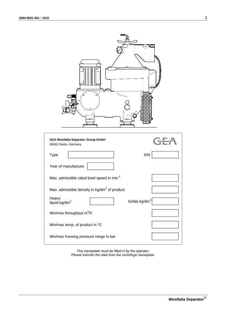
GEA Westfalia Separator Group GmbH
59302 Oelde, Germany Type S/N: Year of manufacture
Max. admissible rated bowl speed in min-1
Max. admissible density in kg/dm3 of product
Heavy liquid kg/dm3
Solids kg/dm3
Min/max throughput m3/h
Min/max temp. of product in °C
Min/max housing pressure range in bar
This nameplate must be filled in by the operator. Please transfer the data from the centrifuge nameplate.

4 2064-9001-001 / 1010
Westfalia Separator®
For your safety
• Take special care when carrying out operations marked with this symbol -
otherwise danger to life!
• Strictly adhere to instructions marked with this symbol.
This avoids damage to the separator and other equipment.
Note: • This symbol is not a safety precaution but rather a reference to infor-mation which help to better understand the separator or plant compo-nents and the processes.
• Observe the accident prevention regulations!
The local safety and accident prevention regulations apply uncondi-tionally to the operation of the separator. The plant operator must en-sure compliance with these regulations.
• When operating electrical apparatus, certain parts carry danger-ous voltage.
Before working in electrical components, take adequate preventive measures according to the national provisions (in Germany in accor-dance with the rules and regulations of the VDE (Verein Deutscher Elektrotechnik / Association of German Electrical Engineering) or of the local electric power company. Non-compliance with the protective measures can result in serious damage to persons or property.
Any work on electrical components may only be carried out by an au-thorized electrician.
• Only qualified or authorized specialized staff may operate, main-tain and repair the separator.
Corresponding training courses take place in the manufacturer’s plant or are held on site by the manufacturer.
• Follow the instructions in the manual.
Follow only the instructions given in this manual. Repair and maintenance work that goes beyond the scope described in this manual may not be carried out.
• Operate the separator only in accordance with agreed process and operating parameters

2064-9001-001 / 1010 5
Westfalia Separator®
• Maintain the separator
as specified in this manual.
• Carry out safety checks on the separator,
as described in chapter "Safety precautions" in this manual
• Liability for the function of the machine passes to the owner.
Liability for the function of the machine passes unconditionally to the owner or operator irrespective of existing warranty periods in so far as the machine is improperly maintained or serviced by persons other than GEA Westfalia Separator service personnel or if the machine is not applied in accordance with the intended use.
GEA Westfalia Separator shall not be liable for damage which occurs as a result of non-observance of the above. Warranty and liability con-ditions in the Conditions of Sale and Delivery of GEA Westfalia Sepa-rator are not extended by the above.
6 2064-9001-001 / 1010
Westfalia Separator®
1 Safety precautions 9
1.1 Correct usage ........................................................................................ 10 1.2 Non-compliance with the intended use .................................................. 11 1.3 Safety markings ..................................................................................... 12 1.3.1 Safety markings and their meaning ....................................................... 13 1.4 Basic operating principles ...................................................................... 17 1.5 Operations on the separator .................................................................. 18 1.5.1 Demands on the operating and maintenance personnel ....................... 18 1.5.2 Spare part requirements ........................................................................ 19 1.5.3 Assembly ............................................................................................... 19 1.5.4 Electrical installation .............................................................................. 22 1.5.5 Before start-up ....................................................................................... 23 1.5.6 Start-up .................................................................................................. 25 1.5.7 Shut-down and “Emergency-Off" ........................................................... 27 1.5.8 Voltage cutoff during operation .............................................................. 28 1.5.9 Maintenance and repair ......................................................................... 29 1.6 Corrosion ............................................................................................... 33 1.7 Erosion ................................................................................................... 34 1.8 The health hazards involved when handling heavy oils and lube oils ... 36 1.8.1 Code of practice and personal protective measures ............................. 36
2 Machine description 37
2.1 Standard dimensioned drawing of the separator ................................... 38 2.2 Section through separator ..................................................................... 40 2.3 General .................................................................................................. 41 2.4 OSE ...-0136-... ...................................................................................... 41 2.4.1 Separator with water content and sludge space monitoring system
(WMS and SMS) for fuel oil treatment ................................................... 42 2.5 Main components of the separator ........................................................ 43 2.5.1 Centripetal pump ................................................................................... 45 2.5.2 Bowl ....................................................................................................... 46 2.5.3 Bowl hydraulics ...................................................................................... 47 2.5.4 Drive ....................................................................................................... 50 2.5.5 Solenoid valve block .............................................................................. 51 2.6 Supervisory equipment .......................................................................... 55 2.6.1 Pressuretransmitter ............................................................................... 55 2.6.2 Water detector ....................................................................................... 56 2.6.3 Solenoid valve ....................................................................................... 58 2.6.4 Vibration monitoring (Option) ................................................................. 60 2.6.5 Speed monitoring ................................................................................... 61 2.7 Product feed line and product discharge line ........................................ 62 2.7.1 Throughput monitoring (product feed line A) ......................................... 62 2.7.2 Throughput determination (product feed line A) - only for control D10 ................................................................................ 63 2.7.3 Pressure monitoring (product discharge line B) .................................... 64 2.8 Technical data ....................................................................................... 65
3 Operation 67
3.1 Technical information ............................................................................. 68

2064-9001-001 / 1010 7
Westfalia Separator®
3.1.1 Separating with the unitrolplus system .................................................. 68 3.1.2 General information on bowl ejection .................................................... 68 3.2 Before start-up ....................................................................................... 70 3.2.1 Before the first start-up – after maintenance and repair ........................ 70 3.2.2 Before every start-up ............................................................................. 72 3.3 Starting the separator ............................................................................ 73 3.4 Monitoring of operation .......................................................................... 74 3.5 Setting the separation time .................................................................... 76 3.5.1 Mathematical calculation ....................................................................... 76 3.6 Ejecting the bowl .................................................................................... 77 3.7 Shutting down the separator .................................................................. 78 3.7.1 Shut-down “Emergency-Off" .................................................................. 80 3.8 Trouble shooting .................................................................................... 82 3.8.1 Trouble shooting .................................................................................... 82 3.8.2 Bowl faults.............................................................................................. 84
4 Installation - Maintenance - Repair 91
4.1 Installation of the separator ................................................................... 92 4.1.1 Transporting the separator .................................................................... 94 4.1.2 Installing the separator .......................................................................... 96 4.1.3 Motor ...................................................................................................... 97 4.1.4 Direction of rotation of the bowl ........................................................... 100 4.1.5 Speed and starting time of the bowl .................................................... 101 4.2 Fitting orifice plates, flow indicator, pressure transmitter .................... 103 4.2.1 Installing the orifice plates ................................................................... 104 4.3 Maintenance and lubrication ................................................................ 105 4.3.1 Maintenance schedule ......................................................................... 105 4.3.2 Hoses and hose pipes ......................................................................... 112 4.3.3 Lubrication ........................................................................................... 113 4.3.4 Lubrication Chart ................................................................................. 116 4.3.5 Table of lubricating oils ........................................................................ 118 4.3.6 Comments on table of lubricating oils for separators from GEA Westfalia Separator ..................................................................... 119 4.4 Bowl ..................................................................................................... 120 4.4.1 Dismantling the bowl ............................................................................ 122 4.4.2 Cleaning the bowl ................................................................................ 138 4.4.3 Cleaning the frame .............................................................................. 139 4.4.4 Cleaning the strainer and the operating water feeding system ........... 139 4.4.5 Cleaning the motor .............................................................................. 140 4.4.6 Important instructions for assembling the bowl ................................... 141 4.4.7 Assembling the bowl ............................................................................ 143 4.4.8 Replacing the polyamide gasket (bowl top) ......................................... 157 4.4.9 Replacing the polyamide gasket (bowl top) ......................................... 159 4.4.10 Reworking the sliding piston ................................................................ 166 4.5 Closing the hood .................................................................................. 167 4.6 Drive ..................................................................................................... 170 4.6.1 Important instructions for fitting and removing the drive ...................... 172 4.6.2 Removing the drive belt and spindle assembly ................................... 174 4.6.3 Dismantling the spindle assembly ....................................................... 178 4.6.4 Dismantling the centrifugal clutch ........................................................ 180 4.6.5 Fitting the spindle assembly ................................................................ 184 4.6.6 Fitting the centrifugal clutch ................................................................. 186 4.6.7 Fitting the motor ................................................................................... 192 4.7 Height adjustment ................................................................................ 197 4.7.1 Bowl height .......................................................................................... 197 4.7.2 Centripetal pump clearance ................................................................. 198 4.8 Final checks after assembling the separator ....................................... 200

8 2064-9001-001 / 1010
Westfalia Separator®
4.9 Before a long-term shut-down of the separator ................................... 200 4.9.1 Preserving the separator ..................................................................... 200 4.9.2 Preserving the motor ........................................................................... 201 4.10 Storage ................................................................................................ 202 4.10.1 After delivery ........................................................................................ 202 4.10.2 Separator ............................................................................................. 202 4.10.3 Control system ..................................................................................... 202 4.11 Before restarting .................................................................................. 203 4.12 Disposal ............................................................................................... 204 4.12.1 Gear and lubricating oils ...................................................................... 204 4.12.2 Cleaning liquids ................................................................................... 205 4.12.3 Separator ............................................................................................. 205 4.13 Standard tools ...................................................................................... 206 4.14 Special tools ........................................................................................ 208
5 Spare parts 211
5.1 Spare part requirements ...................................................................... 212 5.2 Guide to ordering spare parts .............................................................. 212
2064-9001-001 / 1010 9
Westfalia Separator®
1 Safety precautions
1.1 Correct usage ........................................................................................ 10 1.2 Non-compliance with the intended use .................................................. 11 1.3 Safety markings ..................................................................................... 12 1.3.1 Safety markings and their meaning ....................................................... 13 1.4 Basic operating principles ...................................................................... 17 1.5 Operations on the separator .................................................................. 18 1.5.1 Demands on the operating and maintenance personnel ....................... 18 1.5.2 Spare part requirements ........................................................................ 19 1.5.3 Assembly ............................................................................................... 19 1.5.4 Electrical installation .............................................................................. 22 1.5.5 Before start-up ....................................................................................... 23 1.5.6 Start-up .................................................................................................. 25 1.5.7 Shut-down and “Emergency-Off" ........................................................... 27 1.5.8 Voltage cutoff during operation .............................................................. 28 1.5.9 Maintenance and repair ......................................................................... 29 1.6 Corrosion ............................................................................................... 33 1.7 Erosion ................................................................................................... 34 1.8 The health hazards involved when handling heavy oils and lube oils ... 36 1.8.1 Code of practice and personal protective measures ............................. 36

10 2064-9001-001 / 1010
Westfalia Separator®
1.1 Correct usage Centrifugal separators – called separators in short – are used • for the separation of liquid mixtures which consist of two liquids, with simulta-
neous removal of the solids contained in the liquids. • for removing (clarifying) solids from a liquid.
The separator is designed • for a very high bowl speed.
The admissible bowl speed depends on the chemical and physical properties of the product: – Temperature – Density of the fluid and solid components.
• for products which contain no corrosive and erosive components. The aggressiveness of the product influences the careful selection of the bowl material.
Only products conforming to the specifications on the nameplate may be processed.
• in accordance with the method of application of the separator agreed with GEA Westfalia Separator. Refer to the data sheet and contractually agree-ments.
• in accordance with the admissible utilities (cleaning agents, lubricants, operat-ing liquids etc.) specified in the documentation or on the data sheet.
Intended use involves • paying attention to the safety precautions, the instruction manual of the sepa-
rator and the safety markings on the separator. • adhering to the data on the nameplate, e.g. maximum admissible bowl speed.
Further information on the intended use of the separator such as – agreed areas, – density of the product – throughput capacities – temperatures – pressures etc.
is given in the documentation or the data sheet furnished with the documenta-tion.
The contractually agreed conditions agreed with GEA Westfalia Separator on the intended use of the separator must be passed on to the operating personnel by the plant operator.
Any operating mode deviating from this is not intended use and can result in severe damage to property and persons!

2064-9001-001 / 1010 11
Westfalia Separator®
1.2 Non-compliance with the intended use Any use that deviates from the intended use is considered to be non-compliant.
The separator may not be operated by: • Persons who have not read and understood these basic safety precautions. • Persons who have not read and understood the instruction manual of the
separator. • Persons who have not been briefed on proper and correct operation. • Persons who have not been adequately trained. • Persons who have not reached the minimum age of 18 years.
The separator may not be operated • when the product fed does not conform to the specifications on the name-
plate. – Product with excessively high density – Solids with excessively high density – Product with excessively high temperature
• when the max. admissible bowl speed has been exceeded through electrical or electronic manipulation of the drive.
• in an incomplete state of assembly, e.g. – required supervisory equipment is not activated or has been switched off. – the required safety and/or protective covers have not been installed.
• by persons who are not adequately trained.
• when the separator is operated with spare parts which do not come from GEA Westfalia Separator.
Non-compliance with intended use can result in severe damage to prop-erty and persons!
12 2064-9001-001 / 1010
Westfalia Separator®
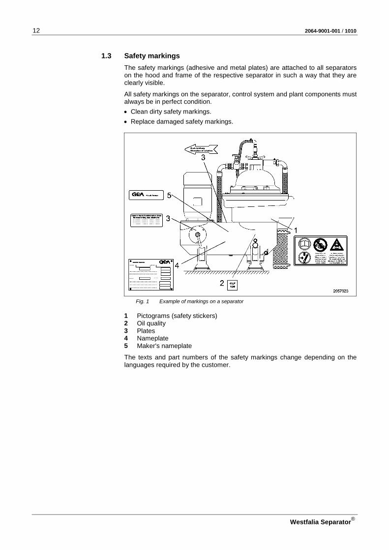
1.3 Safety markings The safety markings (adhesive and metal plates) are attached to all separators on the hood and frame of the respective separator in such a way that they are clearly visible.
All safety markings on the separator, control system and plant components must always be in perfect condition. • Clean dirty safety markings. • Replace damaged safety markings.
Fig. 1 Example of markings on a separator
1 Pictograms (safety stickers) 2 Oil quality 3 Plates 4 Nameplate 5 Maker's nameplate
The texts and part numbers of the safety markings change depending on the languages required by the customer.

2064-9001-001 / 1010 13
Westfalia Separator®
1.3.1 Safety markings and their meaning The following safety markings must be attached to the separator as adhesive labels.
Fig. 2
Refer to the machine documen-tation!
• Every person who is assigned the task of installing, operating, main-taining and repairing the machine must have read and understood the documentation.
• The documentation must be com-plete kept near to the machine and be readily accessible to the opera-tors. It must be available to the op-erators at all times!
Fig. 3

14 2064-9001-001 / 1010
Westfalia Separator®
Before carrying out work, dis-connect power to all compo-nents of the monitoring system! Risk of injury due to electrical voltage and unintended start-up of the separa-tor! Before carrying out work on the separator and electrical plant com-ponents:
• Make sure the separator is at a standstill.
• Switch off all electrical appliances via the main switch,
• Lock the installation to prevent it from being accidentally switched on.
Fig. 4
Danger to life and limb through rotating machine parts!
• Do not loosen any part and do not carry out maintenance or repair work on the separator before the separator is at a standstill.
Methods of how to check standstill are described in the machine docu-mentation.
Fig. 5
Warning of unusual noises or vibrations!
When unusual noises or vibrations occur on the separator: • Immediately shut down the separa-
tor with filled bowl via “emergency-off”.
• Never trigger a bowl ejection! • Evacuate the room. • Do not re-enter the room until the
centrifuge has come to a standstill.
Fig. 6
2064-9001-001 / 1010 15
Westfalia Separator®
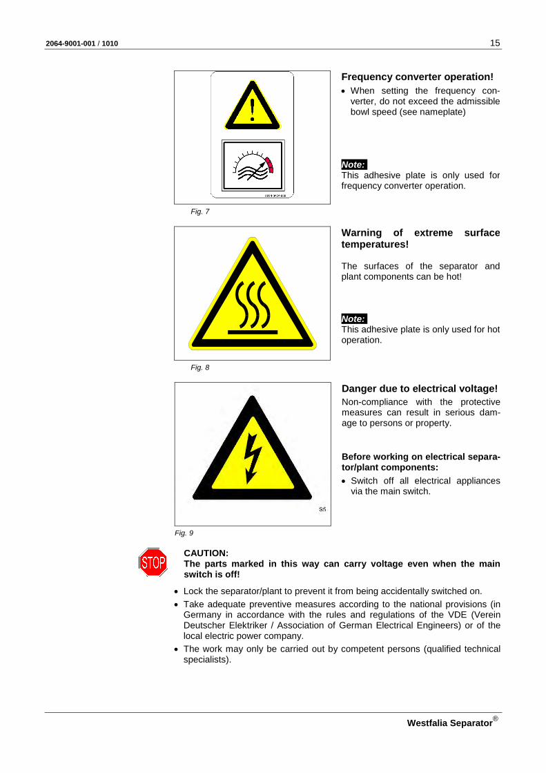
Frequency converter operation!
• When setting the frequency con-verter, do not exceed the admissible bowl speed (see nameplate)
Note: This adhesive plate is only used for frequency converter operation.
Fig. 7
Warning of extreme surface temperatures! The surfaces of the separator and plant components can be hot! Note: This adhesive plate is only used for hot operation.
Fig. 8
Danger due to electrical voltage!
Non-compliance with the protective measures can result in serious dam-age to persons or property. Before working on electrical separa-tor/plant components:
• Switch off all electrical appliances via the main switch.
Fig. 9
CAUTION: The parts marked in this way can carry voltage even when the main switch is off!
• Lock the separator/plant to prevent it from being accidentally switched on. • Take adequate preventive measures according to the national provisions (in
Germany in accordance with the rules and regulations of the VDE (Verein Deutscher Elektriker / Association of German Electrical Engineers) or of the local electric power company.
• The work may only be carried out by competent persons (qualified technical specialists).

16 2064-9001-001 / 1010
Westfalia Separator®
Pictograms with warning text Pictograms can be meaningfully supplemented as illustrated in the two following examples:
– With warning text (Voltage is also present . .), – with signal word (ATTENTION!) and warning text.
Bei ausgeschaltetem
Hauptschalter unter Spannung!
Voltage also present when main
switch is turned off!
Sous tension même
en position d’arrêt de l’interrupteur principal !
Con el interruptor principal desconectado se
encuentra bajo tensión!
Danger through external voltage! Voltage also present when main switch is turned off! CAUTION: The circuits marked in this way can carry voltage even when the main switch is off!
Fig. 10 Example 1
ACHTUNG! Auch bei ausgeschaltetem
Hauptschalter können orangefarbige Leitungen unter Spannung stehen.
ATTENTION! Also in case of switched off
main isolator orange coloured cores can be under voltage.
ATTENTION! Lorsque le commutateur principal
est éteint les files orange peuvent être sous tension.
Danger through external voltage! ATTENTION! Also in case of switched off main isola-tor orange coloured cores can be un-der voltage. CAUTION: The circuits marked in this way can carry voltage even when the main switch is off!
Fig. 11 Example 2
Note : Orange coloured leads are fitted as standard at GEA Westfalia Separator. Different colour leads can be fitted if requested by the customer!

2064-9001-001 / 1010 17
Westfalia Separator®
Potential equalisation (protec-tive-earth terminal)
The grounding protection is a measure which, in the case of a malfunction, leads off the touch voltage into the earth.
Fig. 12
1.4 Basic operating principles Separators are used for the separation of liquid mixtures or for the separation of solids out of liquids or liquid mixtures.
High centrifugal forces are produced in the rotating bowl.
Fig. 13
Under the influence of the centrifugal forces, separation of the liquid mixture and/or ejection of the solids particles takes place most rapidly.
The specifically heavier components are displaced to the bowl periphery, whe-reas the specifically lighter components are displaced towards the centre of the bowl.
The high centrifugal force is produced by very high bowl speeds. On the one hand, high bowl speeds signify high efficiency, while on the other hand, they signify high material stressing of the separator.
18 2064-9001-001 / 1010
Westfalia Separator®
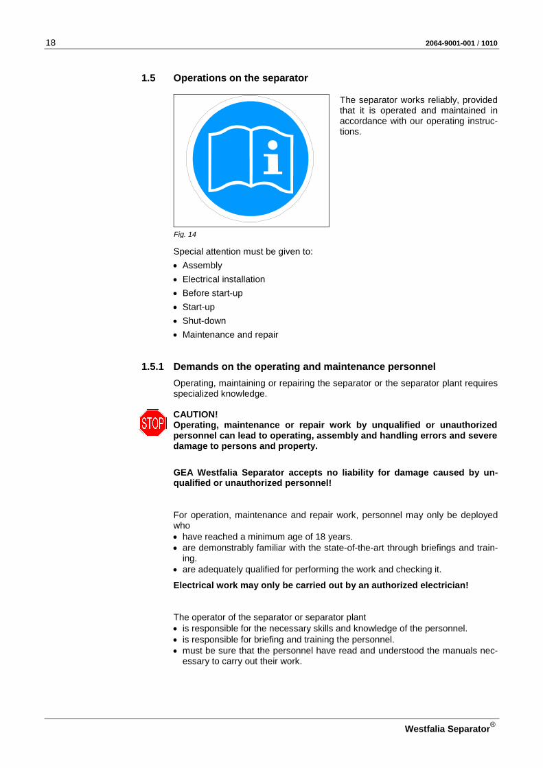
1.5 Operations on the separator
The separator works reliably, provided that it is operated and maintained in accordance with our operating instruc-tions.
Fig. 14
Special attention must be given to: • Assembly • Electrical installation • Before start-up • Start-up • Shut-down • Maintenance and repair
1.5.1 Demands on the operating and maintenance personnel Operating, maintaining or repairing the separator or the separator plant requires specialized knowledge.
CAUTION! Operating, maintenance or repair work by unqualified or unauthorized personnel can lead to operating, assembly and handling errors and severe damage to persons and property.
GEA Westfalia Separator accepts no liability for damage caused by un-qualified or unauthorized personnel!
For operation, maintenance and repair work, personnel may only be deployed who • have reached a minimum age of 18 years. • are demonstrably familiar with the state-of-the-art through briefings and train-
ing. • are adequately qualified for performing the work and checking it.
Electrical work may only be carried out by an authorized electrician!
The operator of the separator or separator plant • is responsible for the necessary skills and knowledge of the personnel. • is responsible for briefing and training the personnel. • must be sure that the personnel have read and understood the manuals nec-
essary to carry out their work.

2064-9001-001 / 1010 19
Westfalia Separator®
GEA Westfalia Separator offers an extensive range of training and advanced training courses. You can obtain further information from GEA Westfalia Sepa-rator or from one of the authorized representatives.
1.5.2 Spare part requirements
• Use only genuine spare parts from GEA Westfalia Separator. The original spare parts are listed in the spare parts catalog. The use of non-genuine parts leads to: – safety risks, – reduced durability of these parts, – reduced availability of the separator and – increased service requirement.
If a safety risk occurs when using non-original spare parts, this may have legal consequences for the responsible persons. In such cases, GEA Westfalia Separator accepts no liability or war-ranty claims.
Fig. 15
1.5.3 Assembly
• If the plant has several centrifuges, be careful not to interchange parts of different bowls since each bowl has been balanced individually. The bowl parts are marked with the serial-number of the machine or with the last three digits of the serial-number.
Fig. 16
• Damaged parts must be replaced immediately by new or reconditioned parts.
Fig. 17

20 2064-9001-001 / 1010
Westfalia Separator®
CAUTION: • Some bowl parts may be pre-
assembled and balanced only by specialists from GEA Westfalia Separator or in workshops au-thorized by Westfalia Separator. Unqualified balancing can lead to dangerous operating states (vi-brations) and destruction of the separator with danger to life.
Fig. 18
• To avoid unbalance, when replacing some bowl parts like – Lock ring – Bowl top – Distributor – Bowl bottom – Water chamber bottom GEA Westfalia Separator must be consulted. These parts – are marked with a footnote in the
separator manual (see section “Bowl”).
– are marked in the column “ETS” of the parts list with a 3 or 4.
Fig. 19
• Some bowl parts are arranged in fixed positions relative to one an-other.
• Locking devices and alignment marks must be in perfect condition. The bowl must otherwise not be op-erated.
Fig. 20
• When transporting and assembling machine parts, avoid crushing and shear strain.
Fig. 21

2064-9001-001 / 1010 21
Westfalia Separator®
• When assembling the bowl, be sure to strictly adhere to the assembly in-structions in order to avoid undue imbalance.
• Before starting the bowl, be sure to fit all parts.
Fig. 22
• Tighten the bowl lock ring securely: the "O" marks on the bowl bottom or bowl top and on the lock ring must be in line with each other.
• Pay attention to the position of the marks!
CAUTION: A loose lock ring can endanger life!
Fig. 23
• Tighten the spindle screw with the separator-specific torque (left-hand thread).
CAUTION: A loose spindle screw can endanger life!
Fig. 24
• Tighten the centripetal pump cham-ber lock ring or cover securely (left-hand thread).
CAUTION: A loose lock ring or cover can en-danger life!
Fig. 25

22 2064-9001-001 / 1010
Westfalia Separator®
• Carefully fasten hood 1, feed and discharge housing 2 and centripetal pump 3.
Fig. 26
• Check if the machine is completely assembled and properly installed.
Fig. 27
1.5.4 Electrical installation
• Electrical work may only be car-ried out by an authorized electri-cian!
• The governing accident prevention regulations apply for the electrical appliances and installations.
• Special attention must be paid to the installation guidelines of GEA West-falia Separator.
• The frequency and voltage of the power supply must correspond to the machine specifications.
Fig. 28
• Carry out voltage equalization.
• Observe legal regulations; e.g. in the EU: – Low-voltage guideline 2006/95/EC, – Electromagnetic compatibility 2004/108/EC, – Guidelines of the classification societies.
2064-9001-001 / 1010 23
Westfalia Separator®
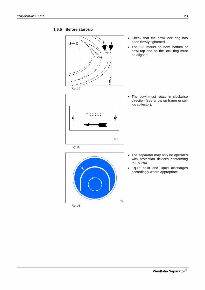
1.5.5 Before start-up
• Check that the bowl lock ring has been firmly tightened.
• The "O" marks on bowl bottom or bowl top and on the lock ring must be aligned.
Fig. 29
• The bowl must rotate in clockwise direction (see arrow on frame or sol-ids collector).
Fig. 30
• The separator may only be operated with protection devices conforming to EN 294.
• Equip solid and liquid discharges accordingly where appropriate.
Fig. 31

24 2064-9001-001 / 1010
Westfalia Separator®
• Check that the lubrication and cool-ing systems are serviceable.
Fig. 32
• Check whether the supervisory equipment is operational and the correct limit values are adjusted.
• When hoods, concentrate collectors and vessels are pressurized, e.g. by – inert gas blanketing, – cooling, – steam sterilization etc. the pressures stated on the boiler plate must not be exceeded.
Fig. 33
• Check that the product lines are set to operation.
• Regularly check hoses for signs of ageing.
• Check sight glasses for mechanical damage.
• Damaged parts must be replaced immediately by new or reconditioned parts.
Fig. 34

2064-9001-001 / 1010 25
Westfalia Separator®
1.5.6 Start-up
• Refer to chapter “operation”.
• Note nameplate. The values for – bowl speed, – density of the heavy liquid, – density of the solids (centrifugally
dry) are maximum values and must not be exceeded.
Fig. 35
• Wear ear protection.
Fig. 36
In case of frequency converter operation:
• Do not under any circumstances manipulate the frequency converter to exceed the permissible bowl speed (see nameplate).
• The separator may only be operated with an independent device for speed limiting.
Fig. 37

26 2064-9001-001 / 1010
Westfalia Separator®
• Do not feed product which is catego-rised as explosive.
• The separator must not be used in areas where explosion protection is required.
Fig. 38
• When processing products harmful to persons, observe the pertinent safety regulations.
• Refer to the safety data sheet of the product.
• Use protective gear, e.g. – Protective clothing – Eye protection – Protective mask
Fig. 39
When unusual noises or vibrations occur on the separator: • Immediately shut down the separa-
tor with filled bowl via “emergency-off”.
• Never trigger a bowl ejection! • Evacuate the room. • Do not re-enter the room until the
separator has come to a standstill.
Fig. 40
Only in case of hot operation:
• Product-contacting parts such as – pipes and hoses, – hood, – solids catcher reach temperatures over 80 oC . (176 oF).
Fig. 41

2064-9001-001 / 1010 27
Westfalia Separator®
• The bowl is not allowed to run with-out liquid supply for more than 15 – 30 minutes, as otherwise it would result in overheating of the bowl ma-terial.
Fig. 42
1.5.7 Shut-down and “Emergency-Off"
• For shut-down of the separator refer to the chapter "Operation" of this manual and follow the start-up and shut-down instructions.
Fig. 43
28 2064-9001-001 / 1010
Westfalia Separator®
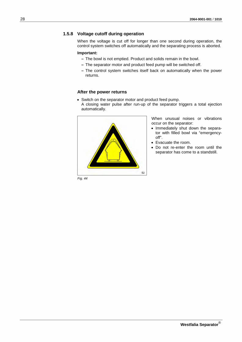
1.5.8 Voltage cutoff during operation When the voltage is cut off for longer than one second during operation, the control system switches off automatically and the separating process is aborted.
Important: – The bowl is not emptied. Product and solids remain in the bowl. – The separator motor and product feed pump will be switched off. – The control system switches itself back on automatically when the power
returns.
After the power returns • Switch on the separator motor and product feed pump.
A closing water pulse after run-up of the separator triggers a total ejection automatically.
When unusual noises or vibrations occur on the separator: • Immediately shut down the separa-
tor with filled bowl via “emergency-off”.
• Evacuate the room. • Do not re-enter the room until the
separator has come to a standstill.
Fig. 44
2064-9001-001 / 1010 29
Westfalia Separator®
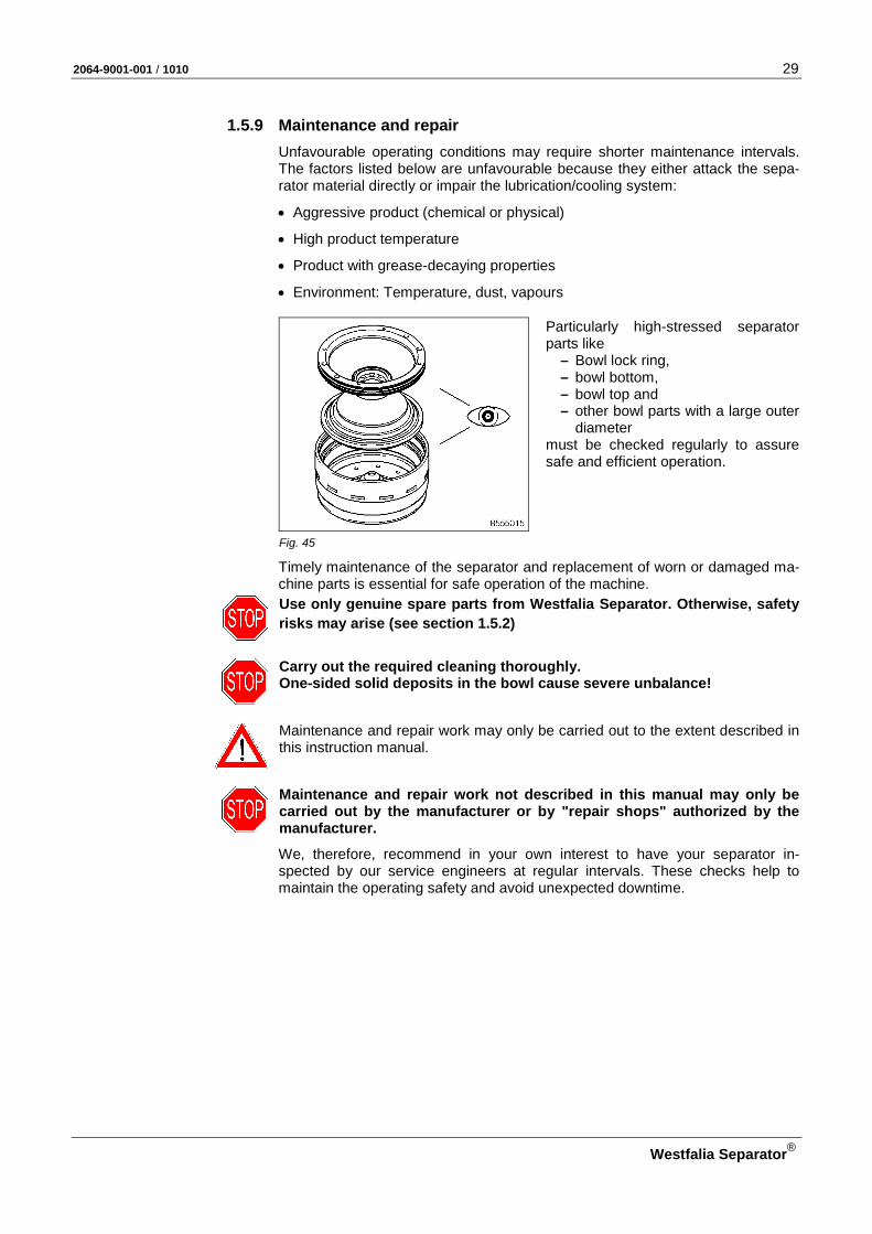
1.5.9 Maintenance and repair Unfavourable operating conditions may require shorter maintenance intervals. The factors listed below are unfavourable because they either attack the sepa-rator material directly or impair the lubrication/cooling system:
• Aggressive product (chemical or physical)
• High product temperature
• Product with grease-decaying properties
• Environment: Temperature, dust, vapours
Particularly high-stressed separator parts like
– Bowl lock ring, – bowl bottom, – bowl top and – other bowl parts with a large outer
diameter must be checked regularly to assure safe and efficient operation.
Fig. 45
Timely maintenance of the separator and replacement of worn or damaged ma-chine parts is essential for safe operation of the machine.
Use only genuine spare parts from Westfalia Separator. Otherwise, safety risks may arise (see section 1.5.2)
Carry out the required cleaning thoroughly. One-sided solid deposits in the bowl cause severe unbalance!
Maintenance and repair work may only be carried out to the extent described in this instruction manual.
Maintenance and repair work not described in this manual may only be carried out by the manufacturer or by "repair shops" authorized by the manufacturer.
We, therefore, recommend in your own interest to have your separator in-spected by our service engineers at regular intervals. These checks help to maintain the operating safety and avoid unexpected downtime.
30 2064-9001-001 / 1010
Westfalia Separator®
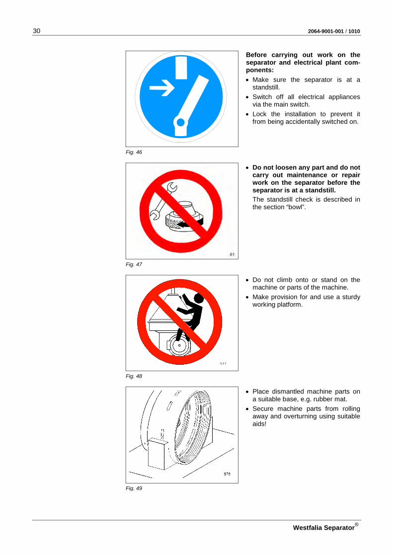
Before carrying out work on the separator and electrical plant com-ponents:
• Make sure the separator is at a standstill.
• Switch off all electrical appliances via the main switch.
• Lock the installation to prevent it from being accidentally switched on.
Fig. 46
• Do not loosen any part and do not carry out maintenance or repair work on the separator before the separator is at a standstill.
The standstill check is described in the section “bowl”.
Fig. 47
• Do not climb onto or stand on the machine or parts of the machine.
• Make provision for and use a sturdy working platform.
Fig. 48
• Place dismantled machine parts on a suitable base, e.g. rubber mat.
• Secure machine parts from rolling away and overturning using suitable aids!
Fig. 49
2064-9001-001 / 1010 31
Westfalia Separator®
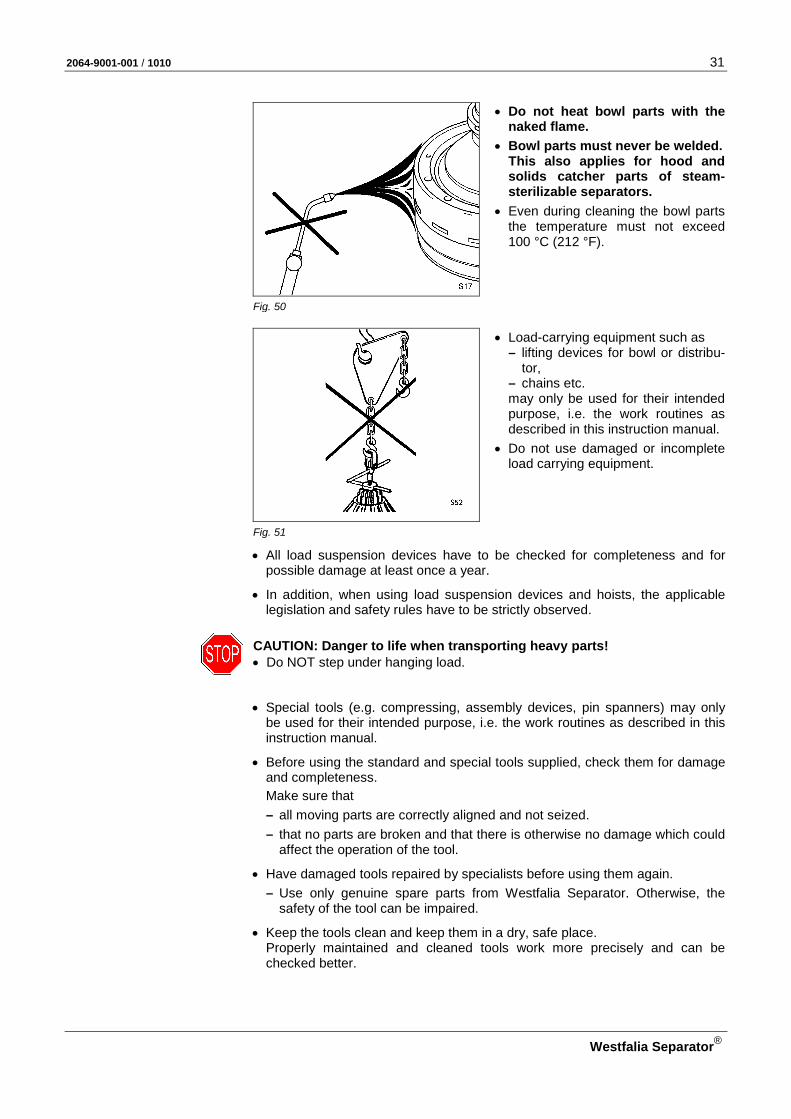
• Do not heat bowl parts with the naked flame.
• Bowl parts must never be welded. This also applies for hood and solids catcher parts of steam-sterilizable separators.
• Even during cleaning the bowl parts the temperature must not exceed 100 °C (212 °F).
Fig. 50
• Load-carrying equipment such as – lifting devices for bowl or distribu-
tor, – chains etc. may only be used for their intended purpose, i.e. the work routines as described in this instruction manual.
• Do not use damaged or incomplete load carrying equipment.
Fig. 51
• All load suspension devices have to be checked for completeness and for possible damage at least once a year.
• In addition, when using load suspension devices and hoists, the applicable legislation and safety rules have to be strictly observed.
CAUTION: Danger to life when transporting heavy parts! • Do NOT step under hanging load.
• Special tools (e.g. compressing, assembly devices, pin spanners) may only be used for their intended purpose, i.e. the work routines as described in this instruction manual.
• Before using the standard and special tools supplied, check them for damage and completeness.
Make sure that – all moving parts are correctly aligned and not seized. – that no parts are broken and that there is otherwise no damage which could
affect the operation of the tool.
• Have damaged tools repaired by specialists before using them again. – Use only genuine spare parts from Westfalia Separator. Otherwise, the
safety of the tool can be impaired.
• Keep the tools clean and keep them in a dry, safe place. Properly maintained and cleaned tools work more precisely and can be checked better.
32 2064-9001-001 / 1010
Westfalia Separator®
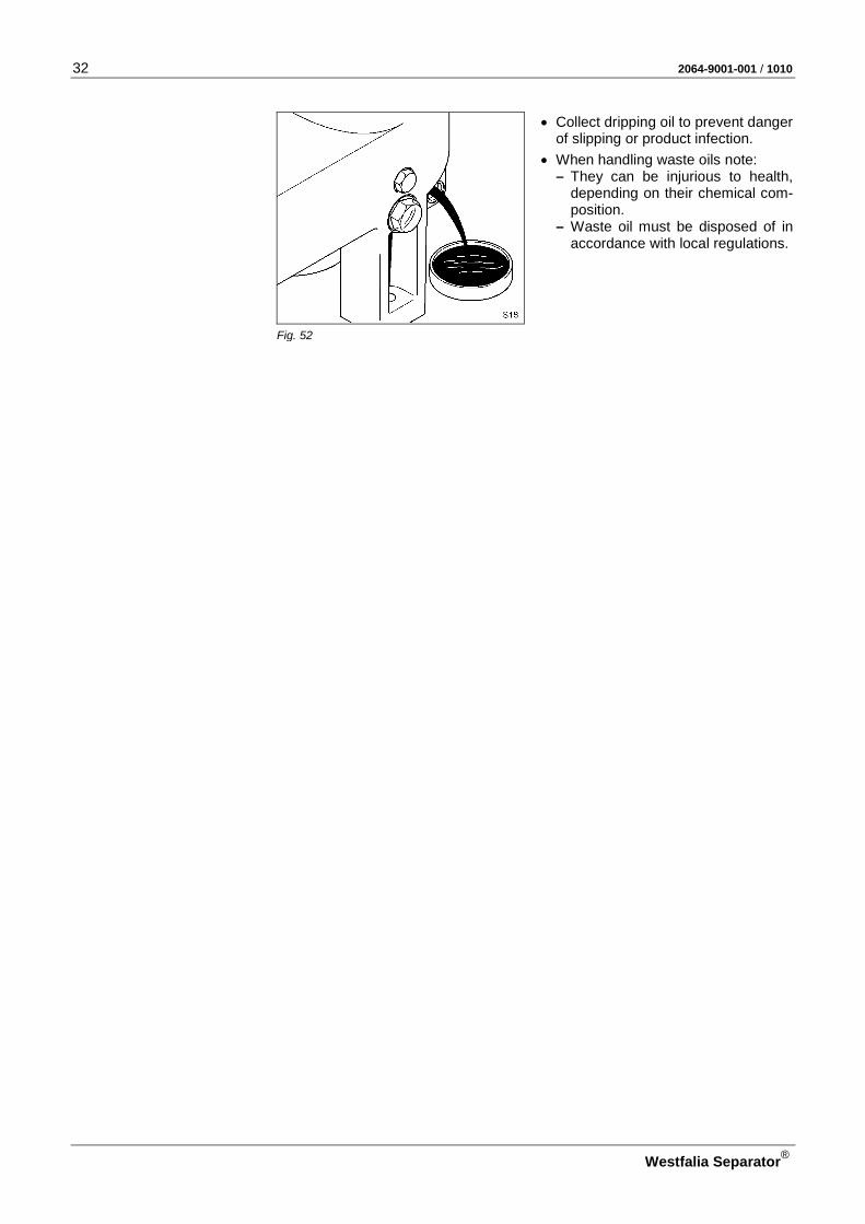
• Collect dripping oil to prevent danger of slipping or product infection.
• When handling waste oils note: – They can be injurious to health,
depending on their chemical com-position.
– Waste oil must be disposed of in accordance with local regulations.
Fig. 52

2064-9001-001 / 1010 33
Westfalia Separator®
1.6 Corrosion Corrosion can also affect bowl parts made of stainless steel. This corrosion can be flat-spread or pit- or crack-shaped and merits special attention.
Corrosion on stainless steel bowl material should be examined thoroughly and documented.
Flat-spread corrosion can usually be measured (reduction of wall thickness)
Pit- or crack-shaped corrosion cannot be measured without the risk of damage. At the initial stage pit-shaped corrosion is generally caused by chlorine ions.
Depending on the stressing of the part, pit-shaped corrosion can result in crack-shaped corrosion.
Possible formation of pit-shaped cor-rosion.
Fig. 53
Such pittings can only be investigated by a materials expert.
In case of crack-shaped corrosion attack with or without superposed flat-spread and pit-shaped corrosion on main bowl components, the machine must be shut down immediately.
Contact your nearest Westfalia Separator representative for a thorough exami-nation.
Pittings
Pittings which are close together or form a linear pattern can signify crack formation beneath the surface.
Such pittings should be investigated by a materials expert.
Fig. 54
34 2064-9001-001 / 1010
Westfalia Separator®
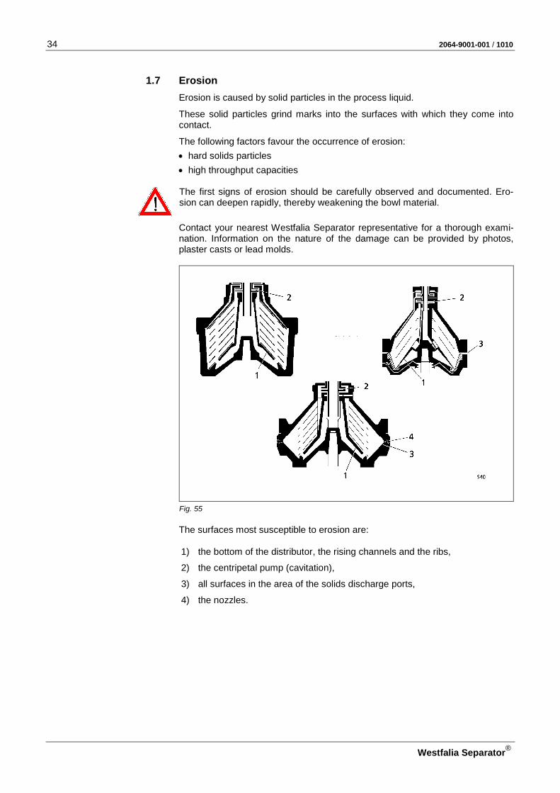
1.7 Erosion Erosion is caused by solid particles in the process liquid.
These solid particles grind marks into the surfaces with which they come into contact.
The following factors favour the occurrence of erosion: • hard solids particles • high throughput capacities
The first signs of erosion should be carefully observed and documented. Ero-sion can deepen rapidly, thereby weakening the bowl material.
Contact your nearest Westfalia Separator representative for a thorough exami-nation. Information on the nature of the damage can be provided by photos, plaster casts or lead molds.
Fig. 55 The surfaces most susceptible to erosion are:
1) the bottom of the distributor, the rising channels and the ribs,
2) the centripetal pump (cavitation),
3) all surfaces in the area of the solids discharge ports,
4) the nozzles.

2064-9001-001 / 1010 35
Westfalia Separator®
Signs of erosion which you should immediately report to your nearest Westfalia Separator representative: • The bottom of the erosion mark has
a radius smaller than 1 mm (large notch effect).
• The depth of erosion mark exceeds 1 mm (0.04 inch) at the deepest point.
Fig. 56

36 2064-9001-001 / 1010
Westfalia Separator®
1.8 The health hazards involved when handling heavy oils and lube oils
As a result of the deterioration in quality of fuel oils, the danger has arisen that the heavy oils used on board contain greater amounts of substances injurious to health. These include: - polycyclic aromatic hydrocarbons, - lead compounds, - chemical residues. An increased amount of polycyclic aromatic hydrocarbons is also present in used lube oils (waste oils). The health hazards for the engine room staff depend to a large extent • on the concentrations of the dangerous substances, • the ambient air (inhalation of oil vapours/oil mist), • the intensity and duration of the contact with the skin or mucous membrane.
Possible short-term effects: • headaches, • dizziness, • nausea, • itching or burning of the skin,
Possible long-term effects: • allergic reactions, especially skin allergies, • festering inflammation of the skin pores (oil-acne), • damage to the central nervous system after inhalation over a long period, • skin cancer caused by direct skin contact over a long period, • Lung cancer or cancer of the digestive organs after inhalation over a long period
(not certain as the causes are difficult to separate from the effects of smoking and alcohol). 1.8.1 Code of practice and personal protective measures
• Avoid skin contact with heavy oils or lube oils if possible! - Wear suitable protective gloves. - Apply a protective ointment to the skin (e.g. ointment no. 76), especially if no protective gloves are
worn! • Avoid breathing in oil vapours if possible! • If possible, improve the air circulation in the room!
Fully open the air regulation flaps in the outlets of the air supply ducts in the centrifuge and filter area. • Wash affected areas of skin frequently and thoroughly!
Apply protective ointment to the skin! • Personal hygiene is of the utmost importance! • Change dirty overalls regularly! • Exercise special care when carrying out maintenance work on and cleaning heavy oil and lube oil cen-
trifuges and filters!

2064-9001-001 / 1010 37
Westfalia Separator®
2 Machine description
2.1 Standard dimensioned drawing of the separator ................................... 38 2.2 Section through separator ..................................................................... 40 2.3 General .................................................................................................. 41 2.4 OSE ...-0136-... ...................................................................................... 41 2.4.1 Separator with water content and sludge space monitoring system
(WMS and SMS) for fuel oil treatment ................................................... 42 2.5 Main components of the separator ........................................................ 43 2.5.1 Centripetal pump ................................................................................... 45 2.5.2 Bowl ....................................................................................................... 46 2.5.3 Bowl hydraulics ...................................................................................... 47 2.5.4 Drive ....................................................................................................... 50 2.5.5 Solenoid valve block .............................................................................. 51 2.6 Supervisory equipment .......................................................................... 55 2.6.1 Pressuretransmitter ............................................................................... 55 2.6.2 Water detector ....................................................................................... 56 2.6.3 Solenoid valve ....................................................................................... 58 2.6.4 Vibration monitoring (Option) ................................................................. 60 2.6.5 Speed monitoring ................................................................................... 61 2.7 Product feed line and product discharge line ........................................ 62 2.7.1 Throughput monitoring (product feed line A) ......................................... 62 2.7.2 Throughput determination (product feed line A) - only for control D10 ................................................................................ 63 2.7.3 Pressure monitoring (product discharge line B) .................................... 64 2.8 Technical data ....................................................................................... 65

38 2064-9001-001 / 1010
Westfalia Separator®
2.1 Standard dimensioned drawing of the separator
Fig. 57 Refer to the project-specific dimensioned drawing!
Filling, displacement and operating water feed
Product discharge
Product feed
Solids discharge Water discharge / operating water discharge
Water discharge/ Opera-ting water discharge
The complete bowl can then be transported over adjacent separators of identical type.
These dimensions must be adhered to!
Do not discharge residuals into public waters!
• Refer to the installation guidelines for further information.
Centre of gravity
Minimum lifting capacity hoist: 100 kg For repair and maintenance
bowl, motor
2064-9001-001 / 1010 39
Westfalia Separator®
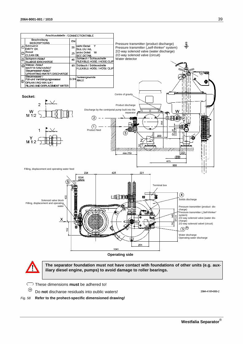
Fig. 58 Refer to the prohect-specific dimensioned drawing!
Water discharge Operating water discharge
Centre of gravity
Solids discharge
Discharge by the centripetal pump built into the separator
Solenoid valve block Filling, displacement and operating
water
These dimensions must be adhered to!
Do not discharge residuals into public waters!
The separator foundation must not have contact with foundations of other units (e.g. aux-iliary diesel engine, pumps) to avoid damage to roller bearings.
Operating side
Socket:
Product discharge
Filling, displacement and operating water feed
Pressure transmitter (product dis-charge) Pressure transmitter („Self-thinker“ system) 2/2-way solenoid valve (water dis-charge) 2/2-way solenoid valvel (circuit)
Terminal box
Pressure transmitter (product discharge) Pressure transmitter („self-thinker“ system) 2/2-way solenoid valve (water discharge) 2/2-way solenoid valve (circuit) Water detector
Product feed

40 2064-9001-001 / 1010
Westfalia Separator®
2.2 Section through separator
Fig. 59

2064-9001-001 / 1010 41
Westfalia Separator®
2.3 General The machine described in this manual is a high-speed centrifugal separator with self-cleaning bowl.
"Separation" means the separation of liquid mixtures which consist of two liq-uids, with simultaneous removal of the solids contained in the liquids.
"Clarification" is the removal of solids from a liquid.
Prerequisite for treatment technology (separation) is that the components of the product
– can be separated mechanically, – have different densities and – do not emulsify.
2.4 OSE ...-0136-... The OSE separator ...-0136-... with unitrolplus-System is equipped with a self-cleaning disk bowl. It is used for clarification and purification of fuel oil (heavy oil up to a density of 1.01 g/ml).
The separator with unitrol plus-System has two built-in monitoring functions: – WMS - (water content monitoring system) – SMS (sludge space monitoring system)

42 2064-9001-001 / 1010
Westfalia Separator®
2.4.1 Separator with water content and sludge space monitoring system (WMS and SMS) for fuel oil treatment The simultaneous water content and sludge space monitoring systems (WMS and SMS) are used for the continuous purification of fuel oil.
Fig. 60 Example of monitoring
1 Dirty oil feed 11 Sensing liquid pump 2 Clean oil discharge 12 Centripetal pump (clean oil) 3 Displacement water 13 Separating disk 4 Pressure transmitter (clean oil) 14 Dirty water discharge 5 Water detector: 15 Solids holding space 6 Pressure transmitter 16 Solids discharge 7 Solenoid valve circuit 17 Operating water discharge 8 Solenoid valve water discharge 18 Operating water feed 9 Partial flow 19 Solenoid valve block
10 Control and monitoring device 20 Throttle
The fuel oil is conveyed to the separator via a separate pump.
The dirty oil feed occurs (1) through a closed line system.
The clean oil is discharged (2) under pressure by centripetal pump (12) via the clean oil discharge.
The bowl is automatically opened and closed for desludging at full bowl speed by means of a solenoid valve (19) in the operating water line.
The partial flow (9) diverted from the bowl via the separating disk (13) and the sensing liquid pump (11) is monitored by a water detector (5) and a pressure transmitter (6). When the water detector (5) registers water (high capacity), the solenoid valve (8) opens and the water is discharged through the dirty water outlet (14). If the high capacity (water) changes due to oil flow (low capacity), the solenoid valve (8) closes and the solenoid valve (7) opens intermittently. The partial flow (9) is then recycled into the dirty oil feed (1).
When the sensing liquid inlet becomes blocked with water or solids accumula-tion in the sludge space (15), the pressure transmitter (6) sends a pulse to the control unit (10 and the automatic ejection program is initiated.
The control and monitoring unit (10) ensures unmanned operation.
2064-9001-001 / 1010 43
Westfalia Separator®
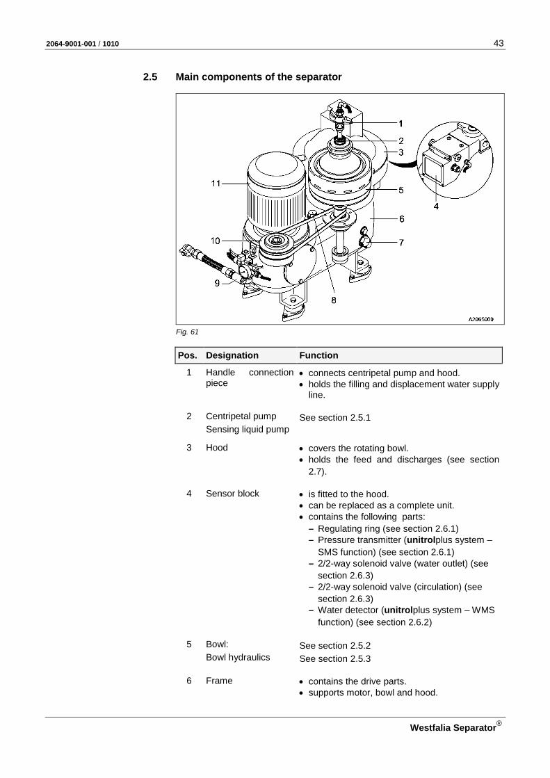
2.5 Main components of the separator
Fig. 61
Pos. Designation Function
1 Handle connection piece
• connects centripetal pump and hood. • holds the filling and displacement water supply
line.
2 Centripetal pump See section 2.5.1 Sensing liquid pump
3 Hood • covers the rotating bowl. • holds the feed and discharges (see section
2.7).
4 Sensor block • is fitted to the hood. • can be replaced as a complete unit. • contains the following parts:
– Regulating ring (see section 2.6.1) – Pressure transmitter (unitrolplus system –
SMS function) (see section 2.6.1) – 2/2-way solenoid valve (water outlet) (see
section 2.6.3) – 2/2-way solenoid valve (circulation) (see
section 2.6.3) – Water detector (unitrolplus system – WMS
function) (see section 2.6.2)
5 Bowl: See section 2.5.2 Bowl hydraulics See section 2.5.3
6 Frame • contains the drive parts.
• supports motor, bowl and hood.
44 2064-9001-001 / 1010
Westfalia Separator®
Pos. Designation Function
7 Sight glass allows checking the oil level.
8 Sight glass for checking the drive belt.
9 Solenoid valve block See section 2.5.5
10 Drive See section 2.5.4
11 Motor • accelerates the separator to the required speed.
• is protected against overload during operation.

2064-9001-001 / 1010 45
Westfalia Separator®
2.5.1 Centripetal pump
Fig. 62
Pos. Designation Function
1 Centripetal pump • discharges the purified liquid under pressure.
• is firmly connected to hood 2 of the separator.
• The disk provided with channels dips into the liquid rotating with the bowl.
• The liquid – is pared off by the centripetal
pump and – flows through its spiral channels
from the outside to the inside. By this means the kinetic energy is converted into pressure energy which makes possible discharging the liquid under pressure.
3 Sensing liquid pump • operates on the same principle as centripetal
pump 1. • conveys the sensing liquid to the monitoring
system.

46 2064-9001-001 / 1010
Westfalia Separator®
2.5.2 Bowl
Fig. 63
Pos. Designation Function
1 Bowl produces high centrifugal forces through rotation making possible separation and clarification.
2 Distributor accelerates the product fed in through feed A to the rotational velocity of the bowl and then con-veys it into the disk stack.
3 Disk stack • splits the liquid mixture consisting of a light and heavy phase, e.g. oil-water, into its com-ponents.
• consists of a large number of conical disks positioned on top of one another.
Each disk is provided with spacers so that pre-cisely defined interspaces are formed between the individual disks. The smooth disk surfaces facilitate sliding of the solids and hence self-cleaning of the disks.
Separation chamber The separation space consists of a large number of parallel chambers of low height. This pro-duces very small radial sedimentation paths for the product.
Solids collect on the upper wall of each disk interspace and slide down into the solids holding space.
4 Solids holding space collects the solids separated in the disk stack.
2064-9001-001 / 1010 47
Westfalia Separator®
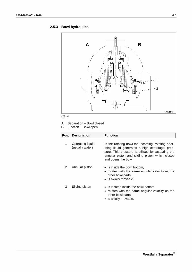
2.5.3 Bowl hydraulics
Fig. 64
A Separation – Bowl closed B Ejection – Bowl open
Pos. Designation Function
1
Operating liquid (usually water)
In the rotating bowl the incoming, rotating oper-ating liquid generates a high centrifugal pres-sure. This pressure is utilised for actuating the annular piston and sliding piston which closes and opens the bowl.
2 Annular piston • is inside the bowl bottom, • rotates with the same angular velocity as the
other bowl parts, • is axially movable.
3 Sliding piston • is located inside the bowl bottom, • rotates with the same angular velocity as the
other bowl parts, • is axially movable.
A B

48 2064-9001-001 / 1010
Westfalia Separator®
Closing the bowl (separation)
Fig. 65
A Separation – Bowl closed B Ejection – Bowl open
After starting the separator the solenoid valve for operating liquid is actuated with the aid of the control unit, and the bowl is closed as follows:
Pos. Designation Function
1 Operating liquid • flows into the injection chamber 4 of bowl
bottom 5 and • from there through feed holes into closing
chamber 6. This initiates closing of the bowl.
2 Annular piston • moves into closed position.
3 Sliding piston • is raised due to the hydrostatic pressure in
closing chamber 6. • is pressed against the gasket 7 of bowl top
due to the hydrostatic pressure and • closes the bowl.
A B
2064-9001-001 / 1010 49
Westfalia Separator®
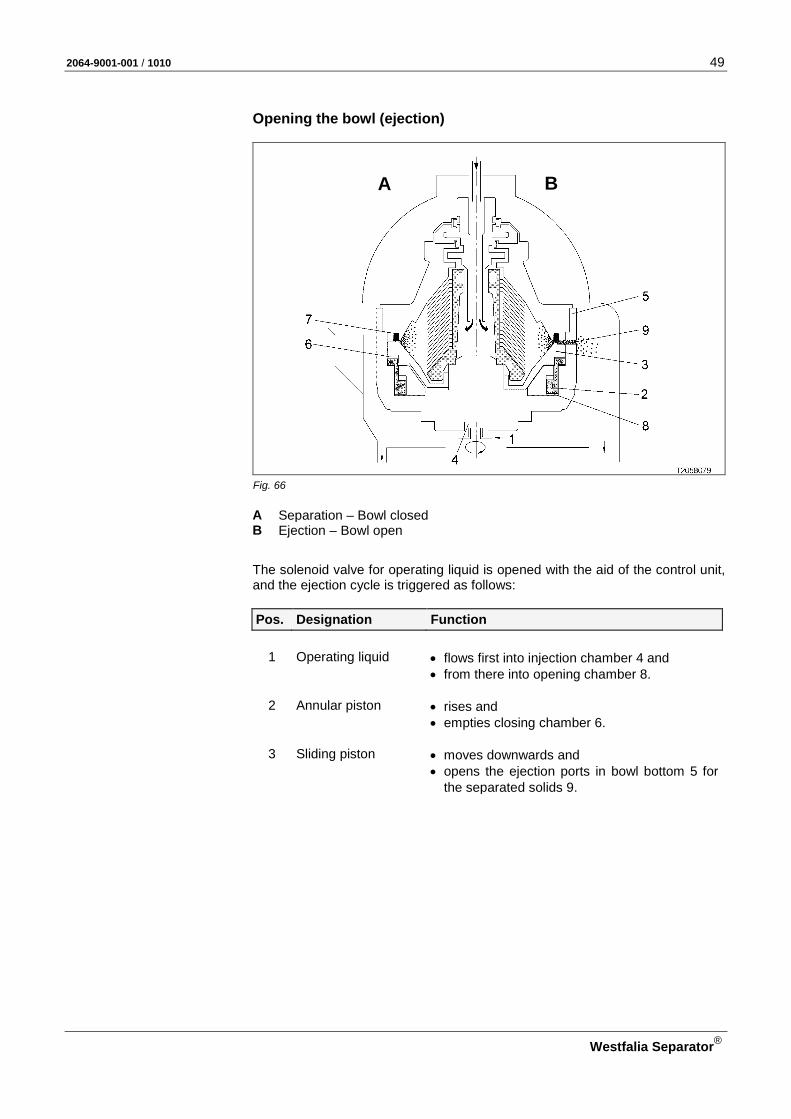
Opening the bowl (ejection)
Fig. 66
A Separation – Bowl closed B Ejection – Bowl open
The solenoid valve for operating liquid is opened with the aid of the control unit, and the ejection cycle is triggered as follows:
Pos. Designation Function
1 Operating liquid • flows first into injection chamber 4 and • from there into opening chamber 8.
2 Annular piston • rises and • empties closing chamber 6.
3 Sliding piston • moves downwards and • opens the ejection ports in bowl bottom 5 for
the separated solids 9.
A B

50 2064-9001-001 / 1010
Westfalia Separator®
2.5.4 Drive
Fig. 67
Pos. Designation Function
1 Drive motor drives the separator. Power transmission to the bowl spindle is via the centrifugal clutch to the motor belt pulley and via the drive belt.
2 Centrifugal clutch • ensures power transmission between motor, drive belt and spindle.
• accelerates the bowl gradually to rated speed;
• is gentle on the drive belt and motor. Important! – The driving effect of new clutch shoes will
improve after several starts. – Smoking of the centrifugal clutch during the
first few starts is perfectly normal and will dis-appear after a short time of operation.
– Wear to the clutch shoes depends on the number of starts and the ejection frequency (see section 4.3.1).
3 Drive belt transfers the drive power of the drive motor 1 to
the bowl spindle 4.
Regularly check the seat and condition of the drive belt. The inspection and replacement inter-vals are given in the maintenance schedule (see 4.3.1).
4 Bowl spindle supports the bowl.
2064-9001-001 / 1010 51
Westfalia Separator®
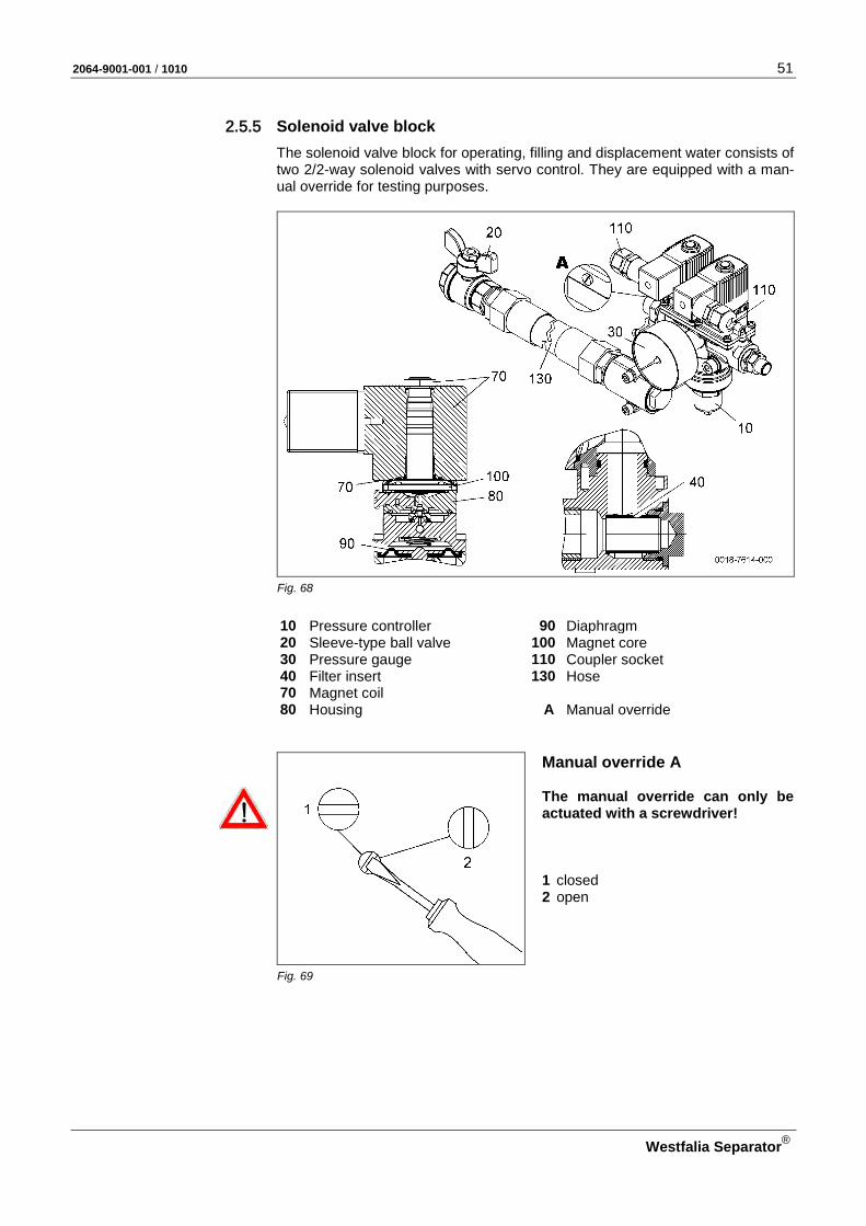
2.5.5 Solenoid valve block The solenoid valve block for operating, filling and displacement water consists of two 2/2-way solenoid valves with servo control. They are equipped with a man-ual override for testing purposes.
Fig. 68
10 Pressure controller 90 Diaphragm 20 Sleeve-type ball valve 100 Magnet core 30 Pressure gauge 110 Coupler socket 40 Filter insert 130 Hose 70 Magnet coil 80 Housing A Manual override
Manual override A The manual override can only be actuated with a screwdriver! 1 closed 2 open
Fig. 69
52 2064-9001-001 / 1010
Westfalia Separator®
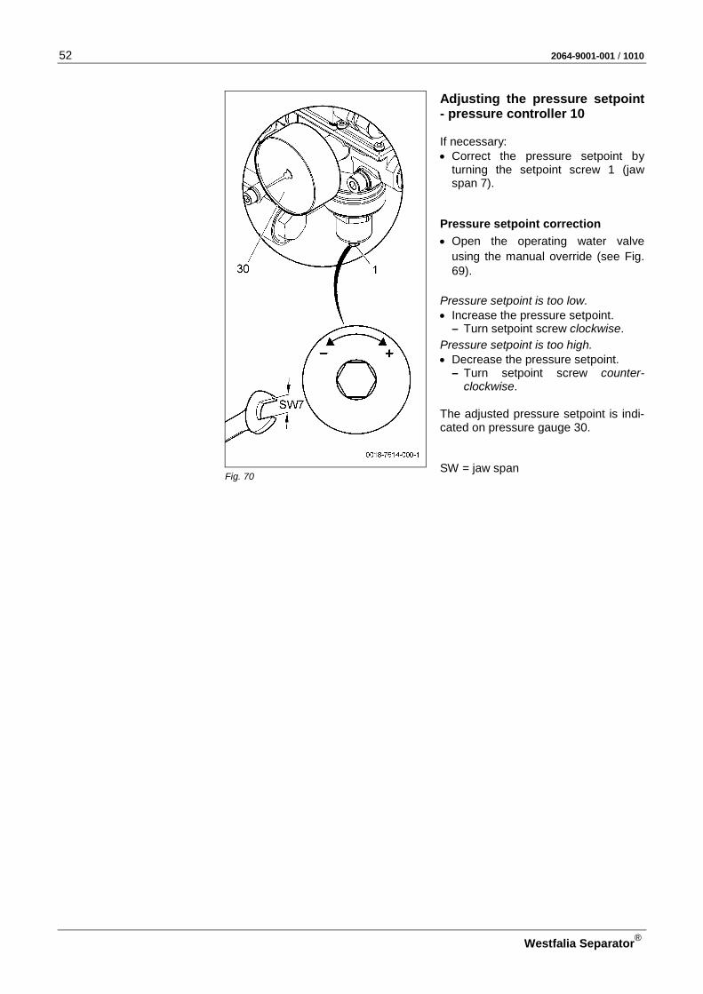
Adjusting the pressure setpoint - pressure controller 10 If necessary: • Correct the pressure setpoint by
turning the setpoint screw 1 (jaw span 7).
Pressure setpoint correction
• Open the operating water valve using the manual override (see Fig. 69).
Pressure setpoint is too low. • Increase the pressure setpoint.
– Turn setpoint screw clockwise.
Pressure setpoint is too high. • Decrease the pressure setpoint.
– Turn setpoint screw counter-clockwise.
The adjusted pressure setpoint is indi-cated on pressure gauge 30. SW = jaw span
Fig. 70

2064-9001-001 / 1010 53
Westfalia Separator®
Technical data
ATTENTION: • Note the specifications on the nameplate of the solenoid valve block and • the installation guidelines.
Part-No. see parts list Operating principles 2/2-way solenoid valve NC Material: Gasket EPDM Housing CuZn Solenoid valves: Coil size 32 mm
Nominal diameter (DN) 13 mm
Operating voltage: 24 V DC Rating 8 W (per solenoid valve)
Coupler socket
with built-in electronics, 24 V DC, LED and free-wheeling diode with fitted cable (1.5 m long)
Pressure Medium 0 to 10 bar Control range 1 to 6 bar Pressure setpoint 2 bar
with open operating water solenoid valve
Temperature: Medium -10 to +80 °C (14 – 176 °F)
In case of electrical faults
CAUTION: Danger due to electrical current! • Switch off the main switch and lock it.
• Close the main valve for operating water, filling and displacement water.
CAUTION: Danger of injury through very hot separator parts! When carrying out maintenance work, there is a danger of injury through hot separator parts (separating temperatures of 70 to 100 oC(158 – 212 °F)).
ATTENTION: • Refer to the instruction manual and nameplate of the solenoid valve block. • Direct intervention in the solenoid valve block only by authorised specialists
and with suitable tools!

54 2064-9001-001 / 1010
Westfalia Separator®
Problem Cause Action
Solenoid valve does not function.
Control unit is defective.
Contact service backup support.
Wire break in the connect-ing terminal.
Replace wire.
Connecting terminal on the connector block is loose.
Tighten the screw of the connecting terminal.
Bad contact on the con-necting terminal.
Clean or replace the con-tact.
Coupler socket loose. Tighten coupler socket.
Magnet coil defective. Replace the solenoid head.
Diaphragm defective. Replace diaphragm.
2064-9001-001 / 1010 55
Westfalia Separator®
2.6 Supervisory equipment The separating process is monitored and controlled by an automatic control unit. For further details, refer to the control unit manual.
2.6.1 Pressuretransmitter
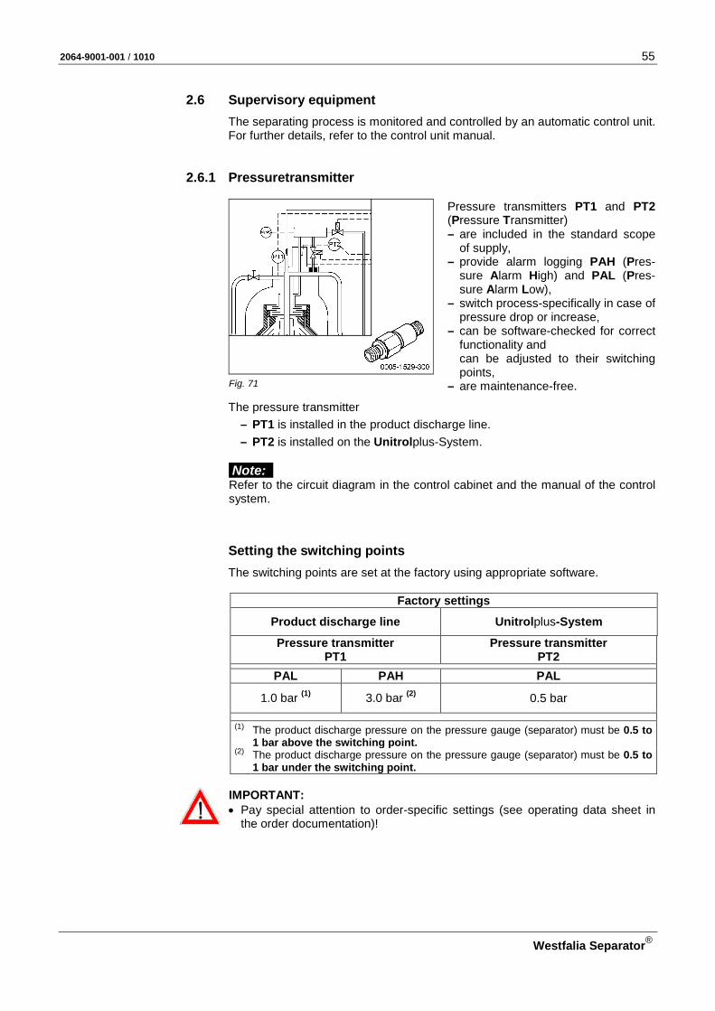
Pressure transmitters PT1 and PT2 (Pressure Transmitter) – are included in the standard scope
of supply, – provide alarm logging PAH (Pres-
sure Alarm High) and PAL (Pres-sure Alarm Low),
– switch process-specifically in case of pressure drop or increase,
– can be software-checked for correct functionality and can be adjusted to their switching points,
– are maintenance-free. Fig. 71
The pressure transmitter – PT1 is installed in the product discharge line. – PT2 is installed on the Unitrolplus-System.
Note:
Refer to the circuit diagram in the control cabinet and the manual of the control system.
Setting the switching points The switching points are set at the factory using appropriate software.
Factory settings
Product discharge line Unitrolplus-System
Pressure transmitter PT1
Pressure transmitter PT2
PAL PAH PAL
1.0 bar (1) 3.0 bar (2) 0.5 bar
(1)
The product discharge pressure on the pressure gauge (separator) must be 0.5 to 1 bar above the switching point.
(2) The product discharge pressure on the pressure gauge (separator) must be 0.5 to 1 bar under the switching point.
IMPORTANT: • Pay special attention to order-specific settings (see operating data sheet in
the order documentation)!
56 2064-9001-001 / 1010
Westfalia Separator®
Technical data
Voltage 24 V DC
Range 0 – 16 bar
Output signal 4 – 20 mA
Pressure connection G 1/4in outer (O-ring seal)
Tightening torque Pressure connection max. 25 Nm Connector plug M 12 x 1; 5-pole
Cable PUR-2 core, 1.5 m Cable box M 12 x 1; 5-pole Pin1-, white; Pin4+, black Enclosure IP 67
Working temperature : -40 to +125 °C (-40 to +257 °F)
Medium temperature
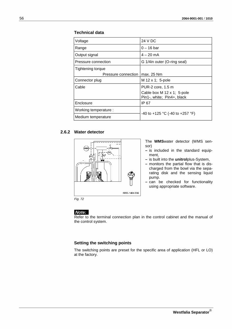
2.6.2 Water detector
The WMSwater detector (WMS sen-sor) – is included in the standard equip-
ment, – is built into the unitrolplus-System, – monitors the partial flow that is dis-
charged from the bowl via the sepa-rating disk and the sensing liquid pump.
– can be checked for functionality using appropriate software.
Fig. 72
Note: Refer to the terminal connection plan in the control cabinet and the manual of the control system.
Setting the switching points The switching points are preset for the specific area of application (HFL or LO) at the factory.
2064-9001-001 / 1010 57
Westfalia Separator®
Technical data
Switching hysteresis Depending on the process HFO/LO Ambient temperature -30 to +125 °C (-22 to +257 °F) (LED: -30 to 100 °C / -22 to 212 °F ) Temperature drift dependent on medium Enclosure (according to IEC 60529) Terminal strip: IP 54 Probe: IP 68 – 10 bar Housing material MS Immersion tube: PTFE Connector plug Terminals See terminal allocation Connection M 30 x 1.5 Jaw span 32 Supply voltage UB 10 to 35 V DC
Conformity EMC (electromagnetic compatibility) according to IEC 60947-5-2)

58 2064-9001-001 / 1010
Westfalia Separator®
2.6.3 Solenoid valve
The solenoid valve is a 2/2-way diaph-ragm straight-way valve with internal piloting. Main components: 1 Diaphragm 2 Emergency locking manual override A Operating mode B Emergency manual override
Fig. 73
Note: The emergency manual override (2) – is secured against accidental activation: see operating status (A). – can be pressed and turned through 90°: see emergency manual override (B).
Technical data
Part-No. see parts list Operating principles 2/2-way valve normally closed Nominal width 3 mm Gasket material FKM Material CuZn Line connection G-1/4 sleeve Voltage 24 V Kind of current DC (direct current) Rating 8 W
In case of electrical faults
CAUTION: Danger due to electrical current! • Switch off the main switch and lock it.
• Close the main valve for operating water, filling and displacement water.
CAUTION: Danger of injury through very hot separator parts! When carrying out maintenance work, there is a danger of injury through hot separator parts (separating temperatures of 70 to 100 oC(158 – 212 °F)).
IMPORTANT: • Refer to the instruction manual and nameplate of the solenoid valve. • Direct intervention in the solenoid valve may only be done by authorised spe-
cialists and with suitable tools!

2064-9001-001 / 1010 59
Westfalia Separator®
Problem Cause Action
Valve does not function.
Control unit is defective.
Contact service backup support.
Wire break in the connect-ing terminal.
Replace wire.
Connecting terminal on the connector block is loose.
Tighten the screw of the connecting terminal.
Bad contact on the con-necting terminal.
Clean or replace the con-tact.
Magnet coil defective. Replace the solenoid head.
Diaphragm defective. Replace diaphragm.

60 2064-9001-001 / 1010
Westfalia Separator®
2.6.4 Vibration monitoring (Option) The separator is protected against inadmissibly high vibrations by means of an electronic vibration monitoring system.
Fig. 74 Installation example
Pos. Designation Function
1 Vibration pick-up • is installed at the upper part of the frame.
• converts the separator vibrations into electric signals.
2 Terminal box • is mounted at the lower part of the frame.
3 Vibration monitoring unit
• is installed in the control cabinet. • evaluates the signals coming from the vibra-
tion pickup.
The evaluation of the signal – depending on the version – takes place in the control cabinet, on the control unit or directly on the vibration pickup.
When the limit value or values are exceeded, an alarm and follow-up measures are triggered and the separator motor switches off automati-cally. The operating status can be read off on the control unit.
ATTENTION! Pay attention to the following instructions and plans: • instruction manual of the vibration monitoring system • instruction manual of the control unit • terminal allocation in the terminal diagram of the control cabinet • circuit diagram
2064-9001-001 / 1010 61
Westfalia Separator®
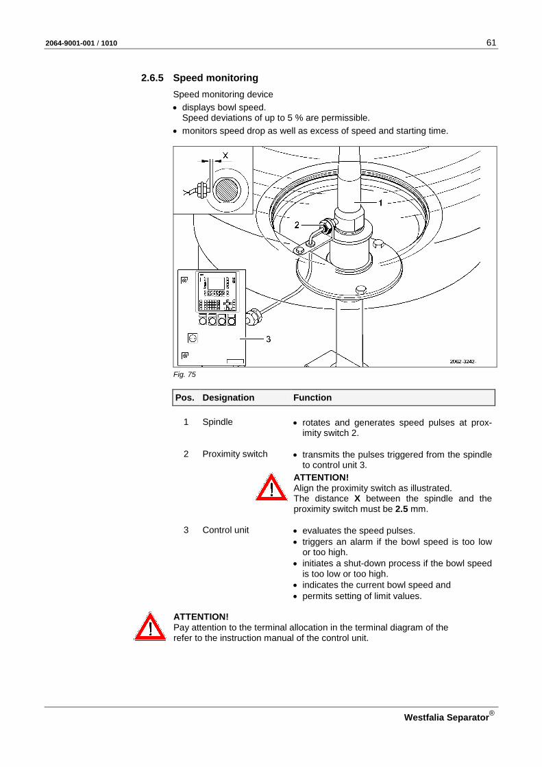
2.6.5 Speed monitoring Speed monitoring device • displays bowl speed.
Speed deviations of up to 5 % are permissible. • monitors speed drop as well as excess of speed and starting time.
Fig. 75
Pos. Designation Function
1 Spindle • rotates and generates speed pulses at prox-imity switch 2.
2 Proximity switch • transmits the pulses triggered from the spindle
to control unit 3.
ATTENTION! Align the proximity switch as illustrated. The distance X between the spindle and the proximity switch must be 2.5 mm.
3 Control unit • evaluates the speed pulses. • triggers an alarm if the bowl speed is too low
or too high. • initiates a shut-down process if the bowl speed
is too low or too high. • indicates the current bowl speed and
• permits setting of limit values.
ATTENTION! Pay attention to the terminal allocation in the terminal diagram of the refer to the instruction manual of the control unit.

62 2064-9001-001 / 1010
Westfalia Separator®
2.7 Product feed line and product discharge line
Fig. 76
The separator is adapted to local conditions for throughput capacity and line pressure by means of orifice plates installed in product feed line A and product discharge line B (see section 4.2).
2.7.1 Throughput monitoring (product feed line A) The effective throughput capacity of the separator is stated on the project de-pendent data sheet.
The inner diameters of the orifice plates required for the different throughput ca-pacities can be read from the following table:
Flowmeter – Scale: 0 – 10
Throughput capacity Inner diameter of orifice plate
[l/h] [mm]
1 000 – 1 400 6 1 400 – 2 200 8 2 200 – 3 300 10 3 300 – 4 800 12 4 800 – 7 000 14
7 000 – 13 000 no orifice plate
When using a D10 control unit • During commissioning mark the respective scale area on flowmeter 4 (see
Fig. 76 with the sticker supplied.

2064-9001-001 / 1010 63
Westfalia Separator®
When using an E10 control unit The effective throughput capacity is displaced on the control unit via the pres-sure transmitter 5. Throughput values deviating between the actual value and the setpoint value can be adapted in the control unit.
2.7.2 Throughput determination (product feed line A) - only for control D10
Fig. 77 Diagram for determining the throughput rate
A Inner diameter of orifice plate (mm) B Throughput capacity (x 1000 l/h) C Scale area of flowmeter
The throughput capacity of the separator (volume of product to be treated fed by unit of time) can be determined with the aid of the diagram.
64 2064-9001-001 / 1010
Westfalia Separator®
3/2-way valve with flow indicator 4 Procedure:
• Read the value on the scale of flowmeter 4 (see Fig. 76). e.g. 3
• From the value read from the scale (e.g. 3) draw a line up to the curve of the inner diameter of the built-in orifice plate A (e.g. Ø 10).
• Read the throughput rate B appearing vertically below: e.g. 2.7 (= 2 700 l/h)
The precision in throughput determination depends on the following characteris-tics of the product to be processed:
– Viscosity – Temperature – Density
The parameters mentioned here can lead to inexact determination of the throughput rate.
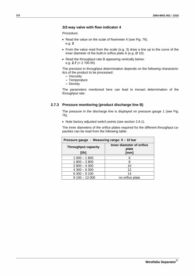
2.7.3 Pressure monitoring (product discharge line B)
The pressure in the discharge line is displayed on pressure gauge 1 (see Fig. 76).
• Note factory adjusted switch points (see section 2.6.1).
The inner diameters of the orifice plates required for the different throughput ca-pacities can be read from the following table:
Pressure gauge - Measuring range: 0 – 10 bar
Throughput capacity Inner diameter of orifice plate
[l/h] [mm]
1 000 – 1 800 6 1 800 – 2 800 8 2 800 – 4 300 10 4 300 – 6 300 12 6 300 – 9 100 14
9 100 – 13 000 no orifice plate
2064-9001-001 / 1010 65
Westfalia Separator®
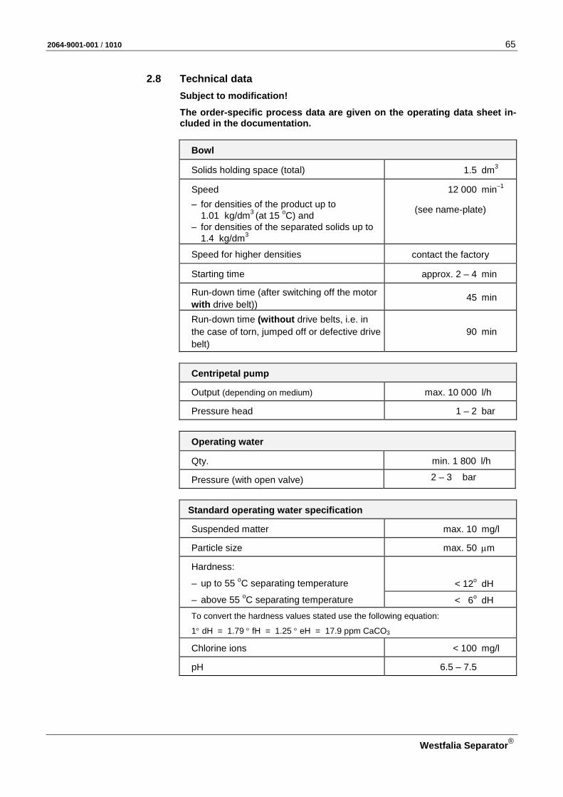
2.8 Technical data Subject to modification!
The order-specific process data are given on the operating data sheet in-cluded in the documentation.
Bowl
Solids holding space (total) 1.5 dm3
Speed 12 000 min–1 – for densities of the product up to
1.01 kg/dm3 (at 15 oC) and (see name-plate)
– for densities of the separated solids up to 1.4 kg/dm3
Speed for higher densities contact the factory
Starting time approx. 2 – 4 min
Run-down time (after switching off the motor with drive belt))
45 min
Run-down time (without drive belts, i.e. in the case of torn, jumped off or defective drive belt)
90 min
Centripetal pump
Output (depending on medium) max. 10 000 l/h
Pressure head 1 – 2 bar
Operating water
Qty. min. 1 800 l/h
Pressure (with open valve) 2 – 3 bar
Standard operating water specification
Suspended matter max. 10 mg/l
Particle size max. 50 µm
Hardness:
– up to 55 oC separating temperature < 12o dH
– above 55 oC separating temperature < 6o dH To convert the hardness values stated use the following equation:
1° dH = 1.79 ° fH = 1.25 ° eH = 17.9 ppm CaCO3
Chlorine ions < 100 mg/l
pH 6.5 – 7.5

66 2064-9001-001 / 1010
Westfalia Separator®
Normal separating temperature of the product
DO 20 °C (68 °F)
MDO 40 °C (104 °F)
LO 90 °C (194 °F)
LO HD 95 °C (203 °F)
HFO 98 °C (208 °F)
Due to the large number of products to be treated, it is not possible to specify an exact separating temperature of the product in this manual. The exact separating temperature of the product (in °C) is stated in the order-specific data sheet.
Motor
Power rating 50 Hz 7.5 kW
60 Hz 8.6 kW
Speed 50 Hz 3 000 RPM
60 Hz 3 600 RPM
Design IM V1
Enclosure IP 55
Drive 50/60 Hz
Oil filling approx. 2.5 l
Oil quality, see section 4.3.3
Product feed pump
Pump unit (gear or screw pump)
Output depending on plant rating
Suction height max. 0.4 bar
Pressure head 2 bar
Weights
Separator (with motor, without bowl) 240 kg
Bowl 70 kg
Motor 53 kg
2064-9001-001 / 1010 67
Westfalia Separator®
3 Operation
3.1 Technical information ............................................................................. 68 3.1.1 Separating with the unitrolplus system .................................................. 68 3.1.2 General information on bowl ejection .................................................... 68 3.2 Before start-up ....................................................................................... 70 3.2.1 Before the first start-up – after maintenance and repair ........................ 70 3.2.2 Before every start-up ............................................................................. 72 3.3 Starting the separator ............................................................................ 73 3.4 Monitoring of operation .......................................................................... 74 3.5 Setting the separation time .................................................................... 76 3.5.1 Mathematical calculation ....................................................................... 76 3.6 Ejecting the bowl .................................................................................... 77 3.7 Shutting down the separator .................................................................. 78 3.7.1 Shut-down “Emergency-Off" .................................................................. 80 3.8 Trouble shooting .................................................................................... 82 3.8.1 Trouble shooting .................................................................................... 82 3.8.2 Bowl faults.............................................................................................. 84

68 2064-9001-001 / 1010
Westfalia Separator®
3.1 Technical information Take note of the following sections:
3.1.1 Separating with the unitrolplus system The separator with unitrol plus-System has two built-in monitoring functions:
– water content monitoring system - WMS – sludge space monitoring system - SMS
Procedure: • Select the desired operating mode on the control unit.
• Set the separating time on the control unit.
• Start the separator (see 3.2).
3.1.2 General information on bowl ejection The bowl is ejected automatically at full speed during the program sequence.
The time at which the ejection is triggered is
• determined by the preset separating time or
• by the solids level in the bowl, if: – SMS was selected on the control unit, – the sludge space is full before the separating time has elapsed.
For determining the separating time see 3.5.
Sequence of an ejection (example without “Filling”)
1. Separating time has elapsed. 2. Product feed valve is closed. 3. Displacement water displaces the fuel oil to the clean oil side. 4. Operating water opens and closes the bowl hydraulically at full bowl
speed. 5. Waiting time for speed recovery. 6. Product valve is opened. 7. Separating time resumes.
Displacement • When separating, the loss of feed liquid unavoidable during ejection can be
reduced to a minimum by displacing the feed liquid with water before sludge ejection takes place (especially important when processing valuable feed liq-uid).
• The duration of displacement water supply is given in the timer overview (see control unit manual).
2064-9001-001 / 1010 69
Westfalia Separator®
• If the displacement time is too long, water will discharge through the light liq-uid outlet.
• If the displacement time is too short, part of the product remains in the bowl and is lost during desludging.
Flush ejection If the solids cant be completely ejected,
– due to an excessively long dwell time in the bowl or – are stuck too firmly on the wall of the solids holding space due to the solids
properties,
• either the separating time must be shortened or • a flush ejection must be carried out after the total ejection by filling the bowl
with water or product and emptying it again.
Program control • "Displacement", "ejection" and "flush ejections" at precisely defined intervals
are best carried out with the automatic control unit.
• The clean oil discharge and water discharge can be monitored.
• Faults can be signalled visually or audibly.

70 2064-9001-001 / 1010
Westfalia Separator®
3.2 Before start-up
Note:
• Safety precautions in chapter 1.
• Instruction manual of the corresponding control unit.
• Instructions “Settings and malfunctions”
• Instruction manuals for other auxiliary equipment
• Process-related deviations are possible (refer to the order-specific operating data sheet!)
3.2.1 Before the first start-up – after maintenance and repair
ATTENTION! In order not to endanger the operating safety of the separator, keep to the recommended maintenance intervals.
If the bowl has been out of operation for longer than 6 months (e.g. due to a long standstill period or storage), • check all bowl parts as specified in the maintenance schedule (table
“Maintenance after 4000 operating hours or after 6 months at the latest”). • Replace if necessary. If the separator has been out of operation for longer than 12 months (e.g. due to a long standstill period or storage), • check all separator parts in accordance with the maintenance schedule
(table “Maintenance after 8000 operating hours or after 1 year at the lat-est),
• replace if necessary.
Ensure that • the sight glass in the frame for observing the drive belt is clean.
• the sight glass in the frame for observing the oil level is clean.
• the drive chamber is filled with oil in accordance with section 4.3.3.
• the bowl height is correct (see section 4.7.1).
• the bowl can be rotated by hand.
• the machine is correctly assembled. – Tighten the bowl top securely (left-hand thread). – Tighten the spindle screw with the separator-specific torque (left-hand
thread). – Tighten the centripetal pump chamber lock ring securely (left-hand
thread).
• the hood is correctly mounted (see 4.5).
• the handle connection piece is tightly bolted to the centripetal pump (see 4.5).
• the hoses and hose pipes are undamaged and connected (see section 4.3.2).

2064-9001-001 / 1010 71
Westfalia Separator®
• the feed and discharge lines are connected (see 4.5).
• the supervisory equipment is complete, mechanically and electrically func-tional.
• the product and supply lines are ready-for-operation. – Pay attention to the air and water pressures (see order-specific operating
data sheet).
• the product heating devices are ready for operation (option). – Pay attention to the volumes, pressure and temperature (see order-specific
operating data sheet).
• the plant components such as valves, water pressure reducer, compressed air control unit etc. are operational.
• the motor is correctly connected (see 4.1.3).
• the motor is correctly mounted.
Important!
• Check the remaining plant components such as hose pipes, sight glasses for signs of aging and mechanical damage.
• Damaged plant components must be replaced immediately by new parts.
72 2064-9001-001 / 1010
Westfalia Separator®
3.2.2 Before every start-up
Ensure that • the sight glass in the frame for observing the drive belt is clean.
• the sight glass in the frame for observing the oil level is clean.
• the drive chamber is filled with oil in accordance with section 4.3.3.
• the machine is correctly assembled. – Tighten the bowl top securely (left-hand thread). – Tighten the spindle screw with the separator-specific torque (left-hand
thread). – Tighten the centripetal pump chamber lock ring securely (left-hand
thread).
• the hood is correctly mounted (see 4.5).
• the handle connection piece is tightly bolted to the centripetal pump (see 4.5).
• the hoses and hose pipes are undamaged and connected (see section 4.3.2).
• the feed and discharge lines are connected (see 4.5).
• the supervisory equipment is complete, mechanically and electrically func-tional.
• the product and supply lines are ready-for-operation. – Pay attention to the air and water pressures (see order-specific operating
data sheet).
• the product heating devices are ready for operation (option). – Pay attention to the volumes, pressure and temperature (see order-specific
operating data sheet).
• the plant components such as valves, water pressure reducer, compressed air control unit etc. are operational.
• the motor is correctly mounted.
Important!
• Check the remaining plant components such as hose pipes, sight glasses for signs of aging and mechanical damage.
• Damaged plant components must be replaced immediately by new parts.
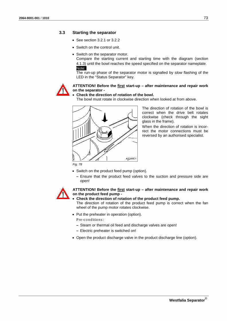
2064-9001-001 / 1010 73
Westfalia Separator®
3.3 Starting the separator
• See section 3.2.1 or 3.2.2
• Switch on the control unit.
• Switch on the separator motor. Compare the starting current and starting time with the diagram (section 4.1.3) until the bowl reaches the speed specified on the separator nameplate. Note: The run-up phase of the separator motor is signalled by slow flashing of the LED in the “Status Separator” key.
ATTENTION! Before the first start-up – after maintenance and repair work on the separator - • Check the direction of rotation of the bowl.
The bowl must rotate in clockwise direction when looked at from above.
The direction of rotation of the bowl is correct when the drive belt rotates clockwise (check through the sight glass in the frame).
When the direction of rotation is incor-rect the motor connections must be reversed by an authorised specialist.
Fig. 78
• Switch on the product feed pump (option). – Ensure that the product feed valves to the suction and pressure side are
open!
ATTENTION! Before the first start-up – after maintenance and repair work on the product feed pump - • Check the direction of rotation of the product feed pump.
The direction of rotation of the product feed pump is correct when the fan wheel of the pump motor rotates clockwise.
• Put the preheater in operation (option).
Pre-conditions : – Steam or thermal oil feed and discharge valves are open! – Electric preheater is switched on!
• Open the product discharge valve in the product discharge line (option).

74 2064-9001-001 / 1010
Westfalia Separator®
• Open the shut-off flap in the solids discharge (option).
1 Shut-off flap 2 Solids tank 3 Solids discharge
Fig. 79
• Start the program.
Pre-conditions : – Continuous lighting of the LED in the “Status Separator” button. – The specified separating temperature has been reached. – The solids tank has been released (level switch LSHH).The solids tank is
empty.
• After the product feed valve has automatically opened. – Set the backpressure in the product discharge line to approx. 1.5 to 2.5 bar
(see order-specific operating data sheet). – Adjust the desired throughput capacity; while doing so, maintain the back-
pressure in the product discharge line in the specified area.
ATTENTION! • Check the discharges for solids and dirty water; there must be no oil flow
during the separating process!
3.4 Monitoring of operation The machine is monitored largely by the separator control.
Operations to be carried out regularly: • On your daily round, especially during the first 1500 operating hours, pay at-
tention to the following: – Oil level – Temperatures – Pressures – Leakage – Vibrations – Current consumption – Starting time – Hoses and hose pipes – Pipe joints
• Keep to the maintenance schedule (see 4.3.1)!
2064-9001-001 / 1010 75
Westfalia Separator®
• Inspection We, therefore, recommend in your own interest to have your separator in-spected by our service engineers once a year. These checks help to – maintain the operating safety of the machine and – avoid unscheduled downtime.
Importan t!
• Regularly check plant components such as hose pipes, sight glasses for signs of aging and mechanical damage.
• Damaged plant components must be replaced immediately by new parts.
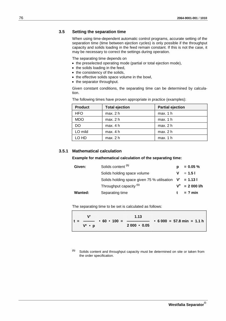
76 2064-9001-001 / 1010
Westfalia Separator®
3.5 Setting the separation time When using time-dependent automatic control programs, accurate setting of the separation time (time between ejection cycles) is only possible if the throughput capacity and solids loading in the feed remain constant. If this is not the case, it may be necessary to correct the settings during operation.
The separating time depends on • the preselected operating mode (partial or total ejection mode), • the solids loading in the feed, • the consistency of the solids, • the effective solids space volume in the bowl, • the separator throughput.
Given constant conditions, the separating time can be determined by calcula-tion.
The following times have proven appropriate in practice (examples):
Product Total ejection Partial ejection HFO max. 2 h max. 1 h MDO max. 2 h max. 1 h DO max. 4 h max. 2 h LO mild max. 4 h max. 2 h LO HD max. 2 h max. 1 h
3.5.1 Mathematical calculation Example for mathematical calculation of the separating time:
Given: Solids content (1) p = 0.05 % Solids holding space volume V = 1.5 l Solids holding space given 75 % utilisation V' = 1.13 l Throughput capacity (1) Vo = 2 000 l/h Wanted: Separating time t = ? min
The separating time to be set is calculated as follows:
V’ 1.13 t = ——— • 60 • 100 = —————— • 6 000 = 57.8 min = 1.1 h
V° • p 2 000 • 0.05
(1) Solids content and throughput capacity must be determined on site or taken from
the order specification.

2064-9001-001 / 1010 77
Westfalia Separator®
3.6 Ejecting the bowl
Automatic operation
• Initiate ejection program by pressing the key ”Process START”:
– Product feed is closed. – Displacement – Bowl ejection – Speed recovery – Filling water (process-dependent)
• The product valve opens again.
Manual operation (in the case of unscheduled shut–down)
• Close the product feed line.
– Close the product feed valve manually.
• Eject the bowl:
– Open the operating liquid valve using the manual override for approx. 2 – 3 seconds.
• Speed recovery
– Wait for approx. 20 – 30 seconds.
• New separating operation
– Open the product feed valve manually.

78 2064-9001-001 / 1010
Westfalia Separator®
3.7 Shutting down the separator
Automatic operation
• End the separation program with the key "Process STOP”. – Two total ejections are performed automatically.
Manual operation (in the case of unscheduled shut–down)
• Switch off the preheater (option). – Continue to feed product for a few minutes since the preheater continues
to heat for a short time.
• Close the product feed line. – Close the product feed valve manually.
• Displacement: – Open the displacement water valve using the manual override.
(The bowl contents are displaced without loss by opening the displace-ment water valve).
• Eject the bowl: – Open the operating liquid valve using the manual override for approx. 2 –
3 seconds.
• Speed recovery – Wait for approx. 20 – 30 seconds.
• Switch off the product feed pump (option). – The product feed pump continues to run (timer 23)! – The LED in the “FEED” button shows the post-run phase by slow flashing. – The control valves for thermal oil and steam preheater close automatically.
ATTENTION! If the control unit or the control voltage 24 VDC fails, the automatic post-run phase of the product feed pump is disabled.
The product feed pump may never be switched off to the steam shut-off valve without a delay time. The pre-heater could get damaged!
All heaters (e.g. steam-fired, thermal oil, electric heaters) must be manually shut down.
Manual shut-down of the product feed pump must be carried out delayed.
• Close the product feed valve in the suction side of the product feed pump (op-tion).
• Switch the separator motor off.
• Close the discharges.
• Close the supply lines such as heating steam, water, compressed air lines with hand valves.
CAUTION: Danger to life through high-speed rotating separator parts! • Do not loosen any part of the separator before the bowl has come to a stand-
still. – The run-down time of the bowl is 45 minutes after switching off the motor. – Bowl standstill is indicated by standstill of the drive belt.

2064-9001-001 / 1010 79
Westfalia Separator®
Standstill of drive belt
• Shine a torch through the frame sight glass.
• Visually check that the drive belt is no longer moving.
Fig. 80
When the sight glass is turbid: • Unscrew the sight glass, • shine a torch through the sight glass opening in the frame!
CAUTION: Danger of injury through rotating drive belt! • Check ONLY visually that the drive belt is no longer moving.
– Do NOT touch the drive belt through the sight glass opening in the frame!
• Clean the sight glass and screw it back in.
CAUTION: Danger to life through high-speed rotating separator parts!
In the case of torn or defective drive belts or if the belts have come off: • Do not loosen any part of the separator before the bowl has come to a stand-
still. • Be sure to observe the run-down time of 90 minutes until dismantling the
separator!
ATTENTION! Only after standstill of the bowl, • Close the shut-off flap in the solids
discharge (option). 1 Shut-off flap 2 Solids tank 3 Solids discharge
Fig. 81
Risk of injury due to electrical volt-age and unintended start-up of the separator! Before carrying out work on the separator and electrical plant com-ponents:
• Switch off all electrical appliances via the main switch.
• Lock the installation to prevent it from being accidentally switched on.
Fig. 82
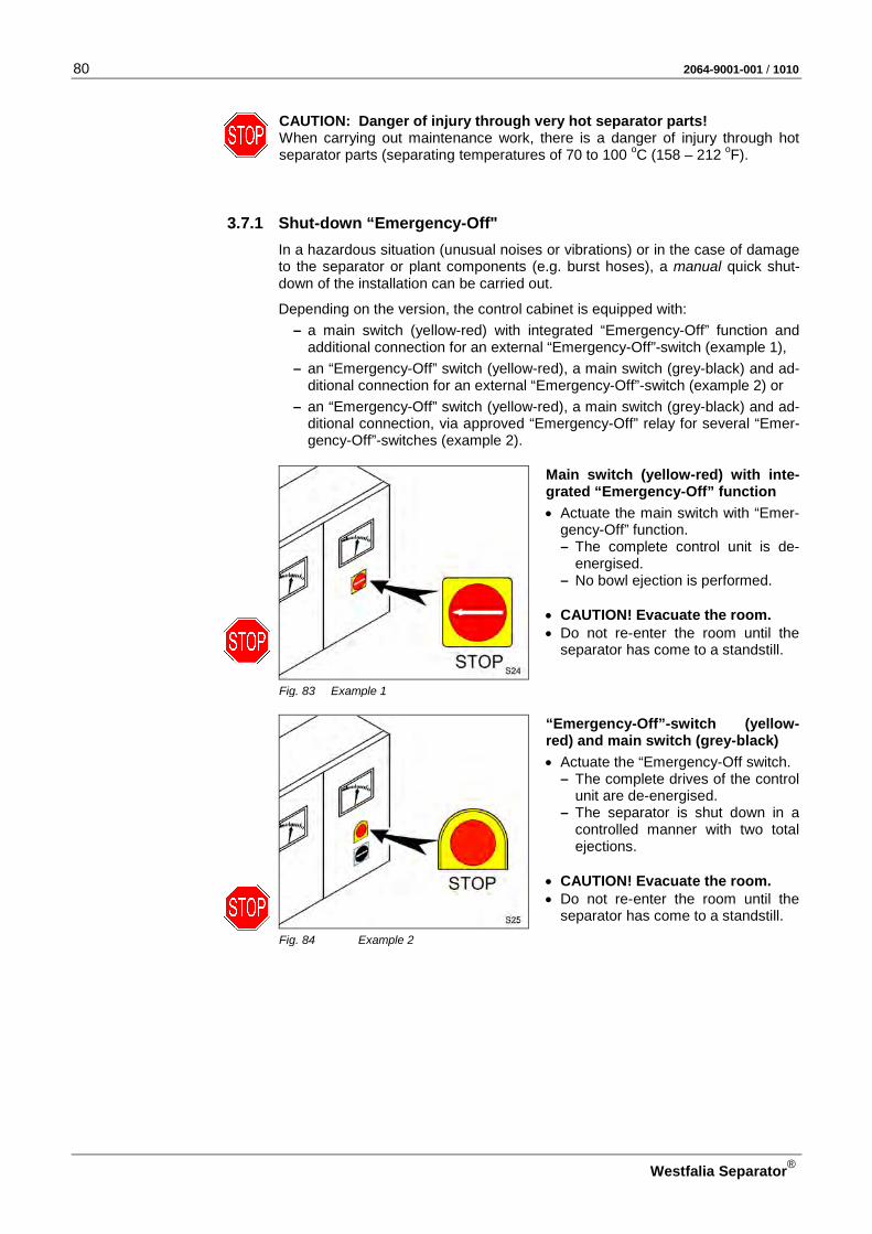
80 2064-9001-001 / 1010
Westfalia Separator®
CAUTION: Danger of injury through very hot separator parts! When carrying out maintenance work, there is a danger of injury through hot separator parts (separating temperatures of 70 to 100 oC (158 – 212 oF).
3.7.1 Shut-down “Emergency-Off" In a hazardous situation (unusual noises or vibrations) or in the case of damage to the separator or plant components (e.g. burst hoses), a manual quick shut-down of the installation can be carried out.
Depending on the version, the control cabinet is equipped with: – a main switch (yellow-red) with integrated “Emergency-Off” function and
additional connection for an external “Emergency-Off”-switch (example 1), – an “Emergency-Off” switch (yellow-red), a main switch (grey-black) and ad-
ditional connection for an external “Emergency-Off”-switch (example 2) or – an “Emergency-Off” switch (yellow-red), a main switch (grey-black) and ad-
ditional connection, via approved “Emergency-Off” relay for several “Emer-gency-Off”-switches (example 2).
Main switch (yellow-red) with inte-grated “Emergency-Off” function
• Actuate the main switch with “Emer-gency-Off” function. – The complete control unit is de-
energised. – No bowl ejection is performed.
• CAUTION! Evacuate the room. • Do not re-enter the room until the
separator has come to a standstill.
Fig. 83 Example 1
“Emergency-Off”-switch (yellow- red) and main switch (grey-black)
• Actuate the “Emergency-Off switch. – The complete drives of the control
unit are de-energised. – The separator is shut down in a
controlled manner with two total ejections.
• CAUTION! Evacuate the room. • Do not re-enter the room until the
separator has come to a standstill. Fig. 84 Example 2

2064-9001-001 / 1010 81
Westfalia Separator®
NNoottee NNootteess
NNoottiizzeenn AAnnoottaacciioonneess ДДлляя ззааппииссеейй MMuuiissttiiiinnppaannoott ΣΣηημμεειιώώσσεειιςς
NNoottaatteerr NNootteess NNoottee

82 2064-9001-001 / 1010
Westfalia Separator®
3.8 Trouble shooting The following tables are an aid for locating and eliminating faults.
If assembly operations have to be carried out refer to the section "Maintenance and Repair".
3.8.1 Trouble shooting Failure Possible causes Action
The bowl does not come up to rated speed or takes too long to do so.
Oil has run down the spindle onto the drive belt; the drive belt is slipping on the bowl spindle.
• Clean belt contact surface of the spindle and clutch pulley.
• Replace the drive belt.
Motor is incorrectly connected. • Check connection.
Insufficient number of clutch shoes. • Increase the number of clutch shoes.
• Make sure that the clutch shoes are evenly spaced.
Drive belt has stretched and is slipping on the bowl spindle.
• Replace drive belt.
Drive belt has not been fitted correctly. • Check position of drive belt on cen-trifugal clutch and bowl spindle.
Liquid or dirt has collected in the upper section of frame and is braking the bowl.
• Check operating water discharge: Liquid must flow off freely.
• Clean inside of upper section of frame.
The bowl speed drops during operation.
Friction surfaces of clutch shoes are oily.
• Wipe dry friction surfaces.
• ATTENTION: Do not use benzene, trichlorethy-lene or any other sol-vent!
Drive belt has stretched and is slipping on the bowl spindle.
• Replace the drive belt.
The motor speed drops during opera-tion.
• Check motor and line voltage.
The bowl reaches the rated speed too fast (in less than 1.5 minutes). The starting current of the motor is hence inadmissibly high.(Imax >2 x IN).
Too many clutch shoes are used. • Reduce the number of clutch shoes.
• Make sure that the clutch shoes are evenly spaced.

2064-9001-001 / 1010 83
Westfalia Separator®
Failure Possible causes Action
Uneven run of the centrifuge. Bowl is out of balance for the following reasons:
For pos. 1 - 4: • Shut down separator. • Close the product feed and dis-
charge.
CAUTION: • Bowl must not be emptied
as otherwise the vibrations occurring during shut-down will intensify.
If bowl leaks, • Completely open the water supply.
1. The separated dirt has deposited unevenly in the bowl.
• Clean bowl.
2. Bowl has not been correctly as-sembled or parts of different bowls (if plant has several separators) have been interchanged.
• Assemble bowl properly.
3. The tension in the disk stack has slackened:
– The bowl top is not screwed on until O mark alignment.
CAUTION: A loose bowl top can endanger life!
• The O marks of the bowl bottom and the bowl top must be aligned.
– Insufficient number of disks. • Check number of disks; add a spare disk if necessary.
4. Bowl parts are damaged. • Send bowl to factory for repair.
CAUTION: Do not carry out your own repairs! Do not weld or solder as this would weaken the bowl!
Ball bearings are worn. • Replace damaged bearings.
ATTENTION! Use only the ball bearings specified in the parts list.

84 2064-9001-001 / 1010
Westfalia Separator®
3.8.2 Bowl faults
Fig. 85 Bowl and operating water feeding system 1 Gasket (bowl top) 11 Operating water feeding system 2 Gasket (bowl top) 12 Injection chamber 3 Gasket (sliding piston) 13 Closing chamber bottom 4 Gasket (annular piston) 14 Bowl bottom 5 Gasket (closing chamber bottom) 15 Drain hole 6 Gasket (annular piston) 16 Annular piston 7 Gaskets (closing chamber bottom) 17 Drain hole 8 Gasket (bowl bottom) 18 Sliding piston 9 Piston guide ring (bowl bottom) 19 Bowl top 10 Gasket (water chamber bottom) 20 Solenoid valve block 21 Solenoid valve for operating water 22 Solenoid valve for filling and displacement water 23 Filling and displacement water line 24 Strainer 25 Shut-off valve 26 Operating water line

2064-9001-001 / 1010 85
Westfalia Separator®
Failure Possible causes Action
The bowl does not close. ATTENTION: – Product flows out of the
solids discharge. – Current consumption is too
high.
Operating water Control unit is defective or • Check the control unit. Motor is not correctly set. • Check or reset program parameters.
(See control unit documentation.)
Closing water pulse too short. • Set 1 seconds (see also control unit documentation).
Strainer 24 in the operating, filling and displacement water line is dirty.
• Close shut-off cock 25. • Clean strainer 24 (see 4.4.4).
The operating water capacity is too low.
• Check line pressure, increase if necessary.
Operating water data: – Pressure 2 – 3 bar (with open valve) – Volume flow min. 1 800 l/h (gauge
the capacity by litres) ≅ 1.0 l in 3 secs
The operating water line 26 has be-come constricted due to dirt accumula-tion or damage. Insufficient operating water is entering the injection cham-ber.
• Clean or replace operating water line 26.
The operating water solenoid valve 21 does not open properly.
• Check solenoid valve 21 and re-place if necessary.
Bowl hydraulics Bowl hydraulic system is soiled.
or • Remove hood and • dismantle and clean the bowl (see
section 4.4.1 and 4.4.2). • Thoroughly clean all bores.
Gaskets and piston guide ring are damaged or
• Replace all sealing elements. Use set of spare parts "bowl/hood“ (see list of spare parts).
Important: Time-consuming instal-lation! • Change polyamide gasket 5 only
when it is damaged (see section 4.4.9).
Sealing rim of sliding piston 18 is damaged.
• Lightly remachine the sealing sur-face of the sliding piston – max. 1 mm! – see section 4.4.10) or
• send in the sliding piston for repair.

86 2064-9001-001 / 1010
Westfalia Separator®
Fig. 86 Bowl and operating water feeding system 1 Gasket (bowl top) 11 Operating water feeding system 2 Gasket (bowl top) 12 Injection chamber 3 Gasket (sliding piston) 13 Closing chamber bottom 4 Gasket (annular piston) 14 Bowl bottom 5 Gasket (closing chamber bottom) 15 Drain hole 6 Gasket (annular piston) 16 Annular piston 7 Gaskets (closing chamber bottom) 17 Drain hole 8 Gasket (bowl bottom) 18 Sliding piston 9 Piston guide ring (bowl bottom) 19 Bowl top 10 Gasket (water chamber bottom) 20 Solenoid valve block 21 Solenoid valve for operating water 22 Solenoid valve for filling and displacement water 23 Filling and displacement water line 24 Strainer 25 Shut-off valve 26 Operating water line
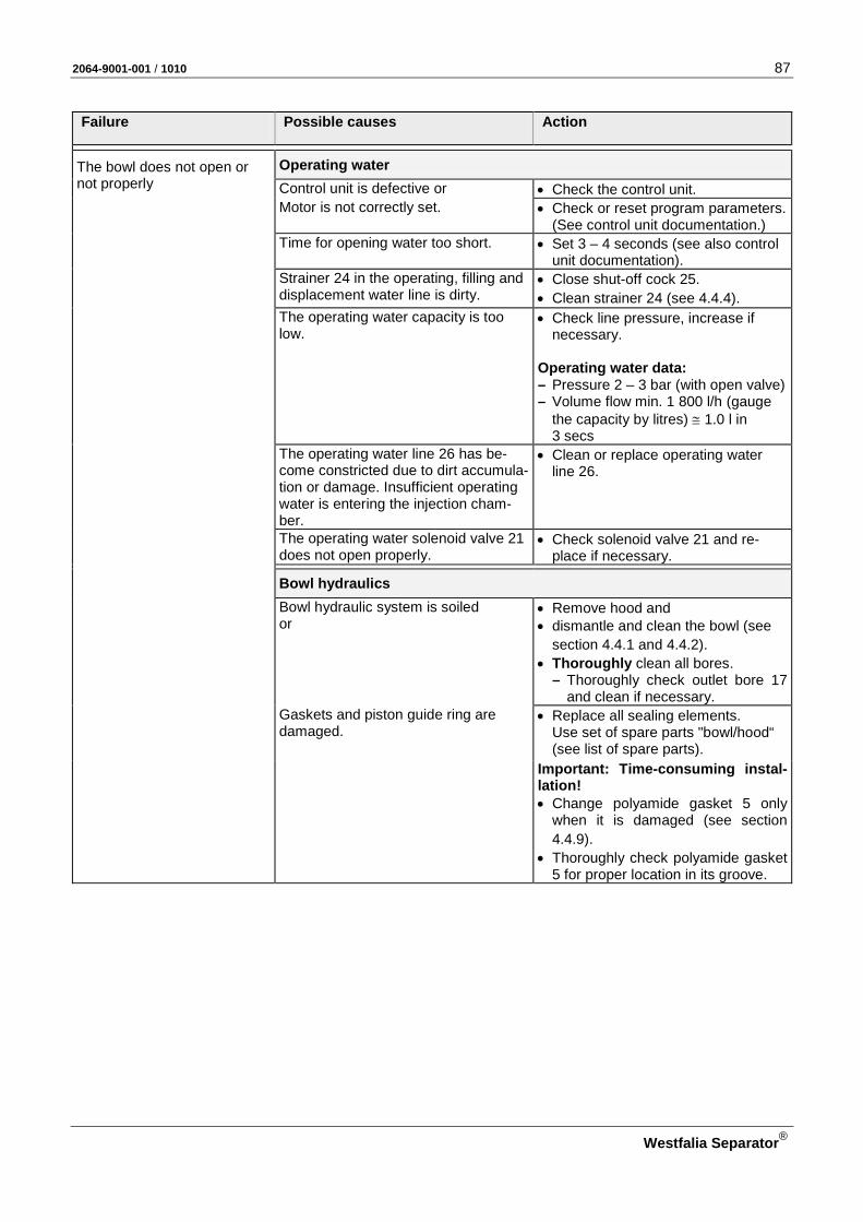
2064-9001-001 / 1010 87
Westfalia Separator®
Failure Possible causes Action
The bowl does not open or not properly
Operating water Control unit is defective or • Check the control unit. Motor is not correctly set. • Check or reset program parameters.
(See control unit documentation.) Time for opening water too short. • Set 3 – 4 seconds (see also control
unit documentation). Strainer 24 in the operating, filling and
displacement water line is dirty. • Close shut-off cock 25. • Clean strainer 24 (see 4.4.4).
The operating water capacity is too low.
• Check line pressure, increase if necessary.
Operating water data: – Pressure 2 – 3 bar (with open valve) – Volume flow min. 1 800 l/h (gauge
the capacity by litres) ≅ 1.0 l in 3 secs
The operating water line 26 has be-come constricted due to dirt accumula-tion or damage. Insufficient operating water is entering the injection cham-ber.
• Clean or replace operating water line 26.
The operating water solenoid valve 21 does not open properly.
• Check solenoid valve 21 and re-place if necessary.
Bowl hydraulics Bowl hydraulic system is soiled
or • Remove hood and • dismantle and clean the bowl (see
section 4.4.1 and 4.4.2). • Thoroughly clean all bores.
– Thoroughly check outlet bore 17 and clean if necessary.
Gaskets and piston guide ring are damaged.
• Replace all sealing elements. Use set of spare parts "bowl/hood“ (see list of spare parts).
Important: Time-consuming instal-lation! • Change polyamide gasket 5 only
when it is damaged (see section 4.4.9).
• Thoroughly check polyamide gasket 5 for proper location in its groove.

88 2064-9001-001 / 1010
Westfalia Separator®
Fig. 87 Bowl and operating water feeding system 1 Gasket (bowl top) 11 Operating water feeding system 2 Gasket (bowl top) 12 Injection chamber 3 Gasket (sliding piston) 13 Closing chamber bottom 4 Gasket (annular piston) 14 Bowl bottom 5 Gasket (closing chamber bottom) 15 Drain hole 6 Gasket (annular piston) 16 Annular piston 7 Gaskets (closing chamber bottom) 17 Drain hole 8 Gasket (bowl bottom) 18 Sliding piston 9 Piston guide ring (bowl bottom) 19 Bowl top 10 Gasket (water chamber bottom) 20 Solenoid valve block 21 Solenoid valve for operating water 22 Solenoid valve for filling and displacement water 23 Filling and displacement water line 24 Strainer 25 Shut-off valve 26 Operating water line

2064-9001-001 / 1010 89
Westfalia Separator®
Failure Possible causes Action
The bowl does not empty completely. Solids remain in the bowl.
The operating water capacity is too low.
• Check line pressure, increase if necessary.
Operating water data: – Pressure 2 – 3 bar (with open valve) – Volume flow min. 1 800 l/h (gauge
the capacity by litres) ≅ 1.0 l in 3 secs
The separating time has been set too long with the result that the solids con-tent is too high.
• Shorten the separating time (see section 3.5).
The bowl opens during sepa-ration.
Closing water pulse is too short. – Closing water evaporates.
• Readjust the closing water impulse (see control unit documentation).
Closing water pulse is too long. – Closing water impulse opens the
bowl.

90 2064-9001-001 / 1010
Westfalia Separator®
NNoottee NNootteess
NNoottiizzeenn AAnnoottaacciioonneess ДДлляя ззааппииссеейй MMuuiissttiiiinnppaannoott ΣΣηημμεειιώώσσεειιςς
NNoottaatteerr NNootteess NNoottee
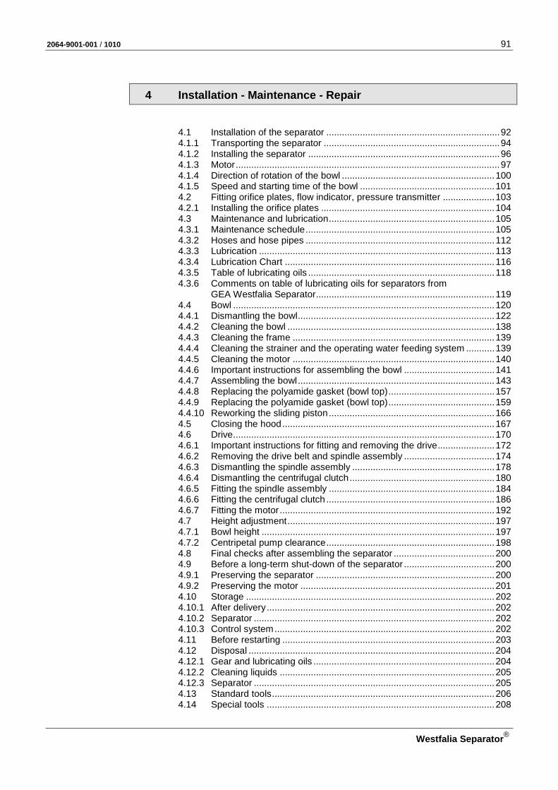
2064-9001-001 / 1010 91
Westfalia Separator®
4 Installation - Maintenance - Repair
4.1 Installation of the separator ................................................................... 92 4.1.1 Transporting the separator .................................................................... 94 4.1.2 Installing the separator .......................................................................... 96 4.1.3 Motor ...................................................................................................... 97 4.1.4 Direction of rotation of the bowl ........................................................... 100 4.1.5 Speed and starting time of the bowl .................................................... 101 4.2 Fitting orifice plates, flow indicator, pressure transmitter .................... 103 4.2.1 Installing the orifice plates ................................................................... 104 4.3 Maintenance and lubrication ................................................................ 105 4.3.1 Maintenance schedule ......................................................................... 105 4.3.2 Hoses and hose pipes ......................................................................... 112 4.3.3 Lubrication ........................................................................................... 113 4.3.4 Lubrication Chart ................................................................................. 116 4.3.5 Table of lubricating oils ........................................................................ 118 4.3.6 Comments on table of lubricating oils for separators from GEA Westfalia Separator ..................................................................... 119 4.4 Bowl ..................................................................................................... 120 4.4.1 Dismantling the bowl ............................................................................ 122 4.4.2 Cleaning the bowl ................................................................................ 138 4.4.3 Cleaning the frame .............................................................................. 139 4.4.4 Cleaning the strainer and the operating water feeding system ........... 139 4.4.5 Cleaning the motor .............................................................................. 140 4.4.6 Important instructions for assembling the bowl ................................... 141 4.4.7 Assembling the bowl ............................................................................ 143 4.4.8 Replacing the polyamide gasket (bowl top) ......................................... 157 4.4.9 Replacing the polyamide gasket (bowl top) ......................................... 159 4.4.10 Reworking the sliding piston ................................................................ 166 4.5 Closing the hood .................................................................................. 167 4.6 Drive ..................................................................................................... 170 4.6.1 Important instructions for fitting and removing the drive ...................... 172 4.6.2 Removing the drive belt and spindle assembly ................................... 174 4.6.3 Dismantling the spindle assembly ....................................................... 178 4.6.4 Dismantling the centrifugal clutch ........................................................ 180 4.6.5 Fitting the spindle assembly ................................................................ 184 4.6.6 Fitting the centrifugal clutch ................................................................. 186 4.6.7 Fitting the motor ................................................................................... 192 4.7 Height adjustment ................................................................................ 197 4.7.1 Bowl height .......................................................................................... 197 4.7.2 Centripetal pump clearance ................................................................. 198 4.8 Final checks after assembling the separator ....................................... 200 4.9 Before a long-term shut-down of the separator ................................... 200 4.9.1 Preserving the separator ..................................................................... 200 4.9.2 Preserving the motor ........................................................................... 201 4.10 Storage ................................................................................................ 202 4.10.1 After delivery ........................................................................................ 202 4.10.2 Separator ............................................................................................. 202 4.10.3 Control system ..................................................................................... 202 4.11 Before restarting .................................................................................. 203 4.12 Disposal ............................................................................................... 204 4.12.1 Gear and lubricating oils ...................................................................... 204 4.12.2 Cleaning liquids ................................................................................... 205 4.12.3 Separator ............................................................................................. 205 4.13 Standard tools ...................................................................................... 206 4.14 Special tools ........................................................................................ 208
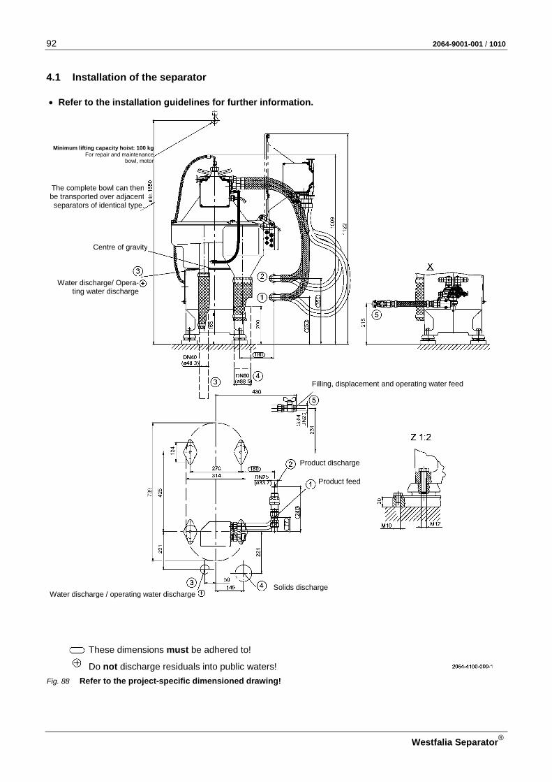
92 2064-9001-001 / 1010
Westfalia Separator®
4.1 Installation of the separator
Fig. 88 Refer to the project-specific dimensioned drawing!
Filling, displacement and operating water feed
Product discharge
Product feed
Solids discharge Water discharge / operating water discharge
Water discharge/ Opera-ting water discharge
The complete bowl can then be transported over adjacent separators of identical type.
These dimensions must be adhered to!
Do not discharge residuals into public waters!
• Refer to the installation guidelines for further information.
Centre of gravity
Minimum lifting capacity hoist: 100 kg For repair and maintenance
bowl, motor

2064-9001-001 / 1010 93
Westfalia Separator®
Fig. 89 Refer to the prohect-specific dimensioned drawing!
Water discharge Operating water discharge
Centre of gravity
Solids discharge
Discharge by the centripetal pump built into the separator
Solenoid valve block Filling, displacement and operating
water
These dimensions must be adhered to!
Do not discharge residuals into public waters!
The separator foundation must not have contact with foundations of other units (e.g. aux-iliary diesel engine, pumps) to avoid damage to roller bearings.
Operating side
Socket:
Product discharge
Filling, displacement and operating water feed
Pressure transmitter (product dis-charge) Pressure transmitter („Self-thinker“ system) 2/2-way solenoid valve (water dis-charge) 2/2-way solenoid valvel (circuit)
Terminal box
Pressure transmitter (product discharge) Pressure transmitter („self-thinker“ system) 2/2-way solenoid valve (water discharge) 2/2-way solenoid valve (circuit) Water detector
Product feed

94 2064-9001-001 / 1010
Westfalia Separator®
4.1.1 Transporting the separator
• CAUTION: Use appropriate lifting devices to prevent accidents! – Be sure to use suitably rated, intact hoists for transport and installation.
• CAUTION: Danger to life under hoists! – Do NOT step under hanging load.
• Always transport the separator without installed bowl!
• For special tools, see section 4.14 or parts list.
• Unscrew the screw plug 1 from the lower part of the frame.
Fig. 90
• Screw double nipple 1 into the hole in the frame.
Fig. 91

2064-9001-001 / 1010 95
Westfalia Separator®
• CAUTION! Do not use the eye bolt of the motor to suspend the sepa-rator.
• ATTENTION: Do not damage any
machine attachment parts when fas-tening the ropes.
• Attach the transport ropes
– to the machine A as illustrated, – around the double nipple and – hang them into the load hook of
the hoist as illustrated. ATTENTION: Prevent the ropes from slipping! • Wind one piece of rope twice round
the hook (see detail).
• Make sure the machine touches down gently.
Fig. 92
• Unscrew double nipple 1
Fig. 93
• Screw in the screw plug 1.
Fig. 94

96 2064-9001-001 / 1010
Westfalia Separator®
4.1.2 Installing the separator • Before installing the separator make sure that
– sufficient space is available for operating and dismantling the machine.
– the foundation is not connected to foundations of other vibrating units to avoid the transfer of vibrations.
• Align separator 1 with feet 2 and plates 3 on foundation 4.
• Tack plates 3.
• Unscrew screws 5.
• Lift separator with feet (see section 4.1.1).
• Weld plates 3 to foundation 4.
• Place the separator on plates 3 and • bolt tight with hexagon nuts 5.
• Screw tight hex head screws 6.
Fig. 95

2064-9001-001 / 1010 97
Westfalia Separator®
4.1.3 Motor
Fig. 96 Start-up diagram (current and speed characteristics) – example
50 Hz 60 Hz De-sign
Enclo-sure *
at 50 Hz 60 Hz
rpm min s kW rpm rpm
see name-plate
approx. 2 – 4 3 7.5 8.6 IM V
1
IP 55
3 000 3 600 ISO-class F *
* WS standard
The separator is driven by a three-phase AC motor via a centrifugal clutch and the drive belt.
The specified motor ratings are minimum values which are based on the in-creased starting current. Since the current consumption of the motor drops after start-up, overloading of the motor during operation is not possible.
The starting time depends on the – flywheel effect of the bowl, – number of clutch shoes used, – condition of the clutch shoes.
The starting current can peak at about 1.8 - 2 times the rated current (see start-up diagram). This is to be considered when selecting switches, lead-in wires and fuses.
The motor – can be started direct online (WS standard) or via a motor control for star-
delta switching (Ex-zone).

98 2064-9001-001 / 1010
Westfalia Separator®
– is protected against overheating by thermal overload releases or a PTC thermistor as sole protection. (As WS standard, the motor is protected against overheating by three PTC thermistors).
– can be equipped with a frequency converter if requested by the customer.
When using thermal overload releases, the motor has to be protected as fol-lows:
– during operation by a release set to the rated current and – during start-up by a second release set to 1.8 - 2 times the rated current.
The release set to the rated current must be bridged during start-up.
Note:
• The temperature feelers must be connected to a commercial tripping device.
• External voltage higher than 2.5 volts must not be applied to the connection terminals of the temperature feelers.
• When testing for continuity, use an ohmmeter and not a test lamp.
Electrical connection
CAUTION: Danger to life and limb through electric current! There might be residual voltage!
In the case of motors with space heaters, residual voltages in the motor terminal box are possible despite switched off main switch. Prior to working on the motor: • Refer to the motor nameplate. • Refer to the motor instruction manual. • Take adequate preventive measures according to the national provisions (in
Germany in accordance with the rules and regulations of the VDE (Associa-tion of German Electrical Engineers) or of the local electric power company.
• Any work on the motor may be carried out by an authorized electrician only.
• Connect the motor. Refer to the motor instruction man-ual.
Fig. 97 Connection scematic
The terminal board in the terminal box can be connected in star or delta.
• Check correct switching of the motor (star or delta). Refer to the motor instruction manual.

2064-9001-001 / 1010 99
Westfalia Separator®
Star switching (example)
Fig. 98
Delta switching (example)
Fig. 99
IMPORTANT: • In the case of additional electrical components, PTC thermistors or space
heaters, refer to the motor manual.
Shipboard operation
• When operating the machine on board of ship, pay attention to the installation guidelines issued by the respective classification societies.
• When using ship wiring cables, cable entry must be by means of marine-type glands.

100 2064-9001-001 / 1010
Westfalia Separator®
4.1.4 Direction of rotation of the bowl
Provided that: – The drive chamber is filled with oil
up to the half way mark on the sight glass.
• Switch on motor.
Fig. 100
The bowl must rotate in clockwise direction when looked at from above.
The direction of rotation of the bowl is correct when the drive belt rotates clockwise (check through the sight glass in the frame).
When the direction of rotation is incor-rect the motor connections must be reversed by an authorised specialist.
Fig. 101
In case of frequency converter operation:
• Before working on the motor, note that residual voltage may be present!
• In this connection: – Read the documentation supplied
by the frequency converter manu-facturer.
– Have protective measures imple-mented by suitably qualified per-sonnel.
Fig. 102
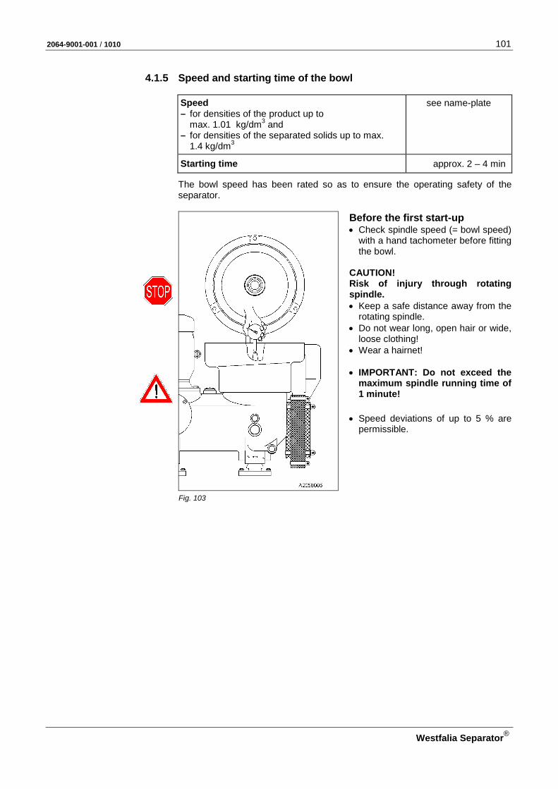
2064-9001-001 / 1010 101
Westfalia Separator®
4.1.5 Speed and starting time of the bowl
Speed – for densities of the product up to
max. 1.01 kg/dm3 and – for densities of the separated solids up to max.
1.4 kg/dm3
see name-plate
Starting time approx. 2 – 4 min
The bowl speed has been rated so as to ensure the operating safety of the separator.
Before the first start-up • Check spindle speed (= bowl speed)
with a hand tachometer before fitting the bowl.
CAUTION! Risk of injury through rotating spindle. • Keep a safe distance away from the
rotating spindle. • Do not wear long, open hair or wide,
loose clothing! • Wear a hairnet! • IMPORTANT: Do not exceed the
maximum spindle running time of 1 minute!
• Speed deviations of up to 5 % are permissible.
Fig. 103

102 2064-9001-001 / 1010
Westfalia Separator®
In case of frequency converter operation: The frequency converter is equipped with a reliable frequency limitation to pre-vent operation at inadmissibly high bowl speeds.
CAUTION! • Operate the separator with fre-
quency converter, speed monitor-ing device and hardware-controlled speed shut-off device.
• Do not under any circumstances manipulate the frequency con-verter to exceed the permissible bowl speed (see nameplate)!
• Check from time to time that – the bowl speed (see nameplate)
and – motor frequency (see nameplate
and frequency converter display!) coincide with the separator speed.
Fig. 104

2064-9001-001 / 1010 103
Westfalia Separator®
4.2 Fitting orifice plates, flow indicator, pressure transmitter A set of orifice plates (with different inner diameters) and a set of commissioning parts are supplied with the separator.
– The set of orifice plates is fastened to the separator hood. – The set of commissioning parts comprises the flow indicator 4 or the pres-
sure transmitter 5.
By installing an orifice plate the separator throughput can be monitored.
Fig. 105
A Product feed line B Product discharge line 1 Pressure gauge 2 Orifice plate 3 Orifice plate 4 Flow indicator (option – for control D10) 5 Pressure transmitter (option – for control E40) 6 3/2-way valve
ATTENTION! Before starting up the separator check that the following parts are installed: Orifice plates 2 and 3 • Select the orifice plates from the set of plates supplied, according to the re-
quired throughput capacity (see section 2.7). • Install orifice plate 3 in product feed line A (see chapter 4.2.1). • Install orifice plate 2 in product feed line B (see chapter 4.2.1). Flow indicator 4 (option – for control D10) • Remove the plug from the corresponding hole of 3/2-way valve 6. • Secure the thread of flowmeter 4 with Loctite 245. • Install flowmeter 4 into 3/2-way valve 6.

104 2064-9001-001 / 1010
Westfalia Separator®
Pressure transmitter 5 (option – for control E40) • Remove the plug from the corresponding hole of 3/2-way valve 6. • Fit pressure transmitter 5 in the 3/2-way valve 6 and connect to the control
unit in accordance with the order-specific circuit diagram. The circuit diagram is kept inside the control cabinet.
4.2.1 Installing the orifice plates Installation of the orifice plates is explained here for product feed line B for ex-ample.
Required material: – Open ended wrench – Lubricating grease
• Unscrew corrugated hose 3. • Insert the selected orifice plate 2 into
connection piece 1 and press in evenly, by hand.
Fig. 106
• Slightly grease the threaded area of connection piece 1
• Insert corrugated hose 3 and firmly tighten with hexagon nut 2.
Fig. 107
2064-9001-001 / 1010 105
Westfalia Separator®
4.3 Maintenance and lubrication
• Special care must be taken when performing maintenance and lubrication operations. Conscientiously performed maintenance and lubrication operations improve the service life of the separator.
• In the case of accessories (motor, product pump, preheater, solenoid valve block etc.) the manufacturer’s maintenance and lubrication instructions must be observed.
• Maintenance and repair work may be carried out only by persons – who are demonstrably familiar with the state-of-the-art through briefings
and training. – who are adequately qualified for performing the work and checking it.
• Electrical work may only be carried out by an authorized electrician!
• Use only genuine spare parts from Westfalia Separator.
4.3.1 Maintenance schedule
ATTENTION! The following maintenance intervals are recommendations which apply only for normal operating conditions. Negative operating conditions (e.g. low-grade fuel, excessively high temperature, strong vibrations, frequent starting and stopping of the separator etc.) can necessitate shorter maintenance intervals.
To assure correct functioning and operating safety,
• in case of non-routine shut-down, see section 3.7 - manual operation.
• Pay attention to the following points during servicing: – Oil level – Temperatures – Pressures – Leakage – Vibrations
– Current consumption – Starting time – Hoses and hose pipes (see 4.3.2) – Pipe joints
• Before every assembly, grease the main components of the bowl at guide and contact surfaces (see section 4.3.4 - lubrication schedule).
• in the case of frequent starting and stopping of the separator, shaft-driven alternator operation and in power plants, the condition of the clutch shoes must be checked more often than stated in this schedule. It is not possible to state a defini-tive time. We recommend checking the clutch shoes after 1000 operating hours or after 2 months at the latest.
• We recommend having the separator checked by a WS service specialist once a year.
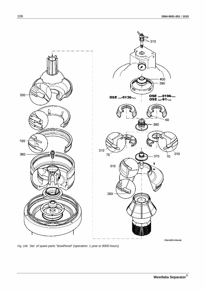
106 2064-9001-001 / 1010
Westfalia Separator®
Fig. 108 Set of spare parts "bowl/hood“ (operation: 1 year or 8000 hours)
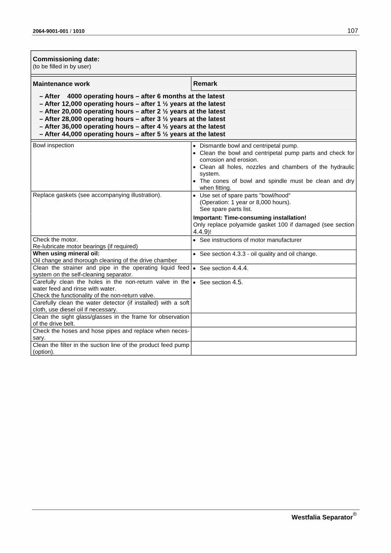
2064-9001-001 / 1010 107
Westfalia Separator®
Commissioning date: (to be filled in by user)
Maintenance work
Remark
– After 4000 operating hours – after 6 months at the latest – After 12,000 operating hours – after 1 ½ years at the latest – After 20,000 operating hours – after 2 ½ years at the latest – After 28,000 operating hours – after 3 ½ years at the latest – After 36,000 operating hours – after 4 ½ years at the latest – After 44,000 operating hours – after 5 ½ years at the latest
Bowl inspection • Dismantle bowl and centripetal pump. • Clean the bowl and centripetal pump parts and check for
corrosion and erosion. • Clean all holes, nozzles and chambers of the hydraulic
system. • The cones of bowl and spindle must be clean and dry
when fitting. Replace gaskets (see accompanying illustration). • Use set of spare parts "bowl/hood“
(Operation: 1 year or 8,000 hours). See spare parts list.
Important: Time-consuming installation! Only replace polyamide gasket 100 if damaged (see section 4.4.9)!
Check the motor. Re-lubricate motor bearings (if required)
• See instructions of motor manufacturer
When using mineral oil: Oil change and thorough cleaning of the drive chamber
• See section 4.3.3 - oil quality and oil change.
Clean the strainer and pipe in the operating liquid feed system on the self-cleaning separator.
• See section 4.4.4.
Carefully clean the holes in the non-return valve in the water feed and rinse with water. Check the functionality of the non-return valve.
• See section 4.5.
Carefully clean the water detector (if installed) with a soft cloth, use diesel oil if necessary. Clean the sight glass/glasses in the frame for observation of the drive belt.
Check the hoses and hose pipes and replace when neces-sary.
Clean the filter in the suction line of the product feed pump (option).
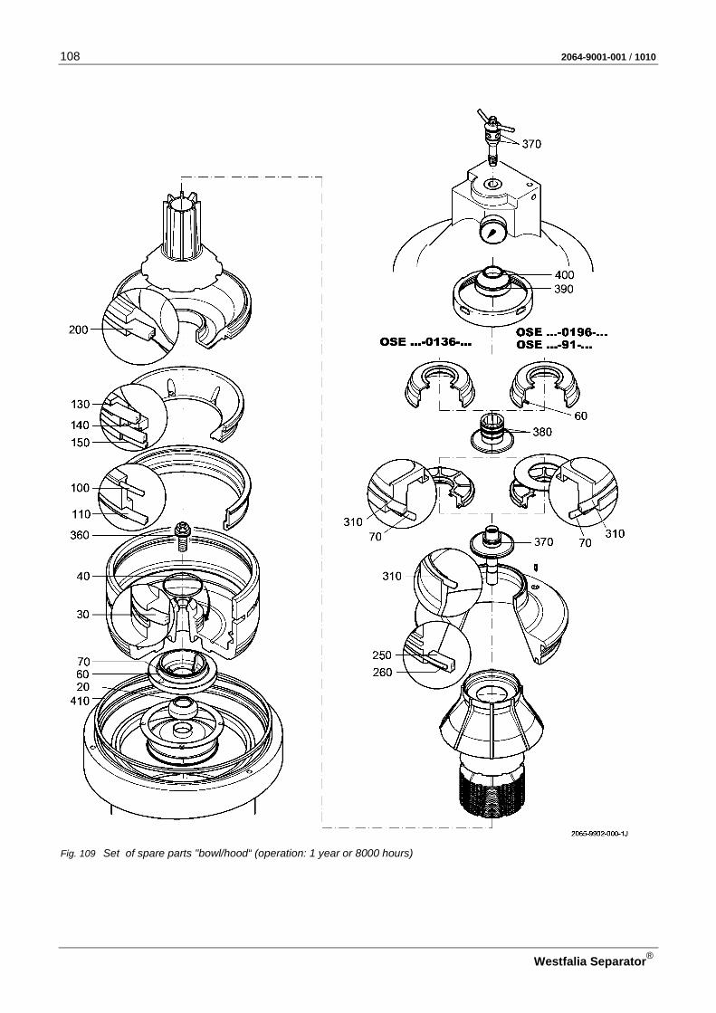
108 2064-9001-001 / 1010
Westfalia Separator®
Fig. 109 Set of spare parts "bowl/hood“ (operation: 1 year or 8000 hours)

2064-9001-001 / 1010 109
Westfalia Separator®
Maintenance work
Remark
– After 8000 operating hours – after 1 year at the latest – After 24,000 operating hours – after 3 years at the latest – After 40,000 operating hours – after 5 years at the latest
Bowl inspection • Dismantle bowl and centripetal pump. • Clean the bowl and centripetal pump parts and check for
corrosion and erosion. • Clean all holes, nozzles and chambers of the hydraulic
system. • The cones of bowl and spindle must be clean and dry
when fitting. Replace gaskets and piston guide ring (see adjacent fig-ure).
• Use set of spare parts "bowl/hood“ (Operation: 1 year or 8000 hours). See parts list.
Important: Time-consuming installation! Change the polyamide gasket only when it is damaged (see section 4.4.9).
Clean the inside of the upper section of frame. • Remove bowl. Replace gaskets. • Use set of spare parts "drive"
(Operation: 1 year or 8000 hours). See parts list.
Replace the drive belt. Replace grooved ball bearings and angular contact ball bearings of spindle. Replace vibration absorber. Check grooved ball bearings of centrifugal clutch and re-place if necessary.
• Use set of spare parts "drive" (Operation: 2 years or 16,000 hours). See parts list. Check thickness of the clutch shoes (1) and replace when
h smaller than 18 mm.
New condition of clutch shoe h = 26 mm Check the motor. Re-lubricate motor bearings (if required)
• See instructions of motor manufacturer
Oil change and thorough cleaning of the drive chamber When using mineral oil (2) When using synthetic oil (2)
Check the bowl height. • See section 4.7.1. In case of direct current: Check the spindle speed (bowl).
• Check only after motor or drive replacement. • See section 4.1.5.
Check the starting time. • See section 4.1.5. Clean the strainer and pipe in the operating liquid feed system on the self-cleaning separator.
• See section 4.4.4
Carefully clean the holes in the non-return valve in the water feed and rinse with water. Check the functionality of the non-return valve.
• See section 4.5.
Carefully clean the water detector (if provided) with a soft cloth, use diesel oil if necessary. Clean the sight glass(es) in the frame for observing the drive belt.
Check the hoses and hose pipes and replace when neces-sary.
Check that vibration absorbers are fully functional (option). Clean the filter in the suction line of the product feed pump (option).
(1) In the case of frequent starting and stopping of the separator, shaft-driven alternator operation and power plants shorter maintenance intervals are required It is not possible to state a definitive time. We recommend checking the clutch shoes after 1,000 operating hours or after 2 months at the latest.
(2) See section 4.3.3 - Oil quality and oil change

110 2064-9001-001 / 1010
Westfalia Separator®
Fig. 110 Set of spare parts "bowl/hood“ (operation: 1 year or 8000 hours)

2064-9001-001 / 1010 111
Westfalia Separator®
Maintenance work
Remark
– After 16,000 operating hours – after 2 years at the latest – After 32,000 operating hours – after 4 years at the latest – After 48,000 operating hours – after 6 years at the latest
Bowl inspection • Dismantle bowl and centripetal pump. • Clean the bowl and centripetal pump parts and check for
corrosion and erosion. • Clean all holes, nozzles and chambers of the hydraulic
system. • The cones of bowl and spindle must be clean and dry
when fitting. Replace gaskets, piston guide ring and guide strips (see adjacent figure).
• Use set of spare parts "bowl/hood“ (Operation: 1 year or 8000 hours). See parts list.
Important: Time-consuming installation! Change the polyamide gasket only when it is damaged (see section 4.4.9).
Clean the inside of the upper section of frame. • Remove bowl. Replace gaskets. • Use set of spare parts "drive"
(Operation: 2 years or 16,000 hours). See parts list.
Replace the drive belt. Replace grooved ball bearings and angular contact ball bearings of spindle. Replace vibration absorber. Replace grooved ball bearings of centrifugal clutch. Check thickness of the clutch shoes (1) and replace when
h smaller than 18 mm.
New condition of clutch shoe h = 26 mm Check the motor. Re-lubricate motor bearings (if required)
• See instructions of motor manufacturer
Oil change and thorough cleaning of the drive chamber When using mineral oil (2) When using synthetic oil (2)
Check the bowl height. • See section 4.7.1. In case of direct current: Check the spindle speed (bowl).
• Check only after motor or drive replacement. • See section 4.1.5.
In case of three-phase current: Check the spindle speed (bowl).
• Check only after drive replacement. • See section 4.1.5.
Check the starting time. • See section 4.1.5. Clean the strainer and pipe in the operating liquid feed system on the self-cleaning separator.
• See section 4.4.4
Carefully clean the holes in the non-return valve in the operating water feed. Check the functionality of the non-return valve.
• See section 4.5.
Carefully clean the water detector (if provided) with a soft cloth, use diesel oil if necessary. Clean the sight glass(es) in the frame for observing the drive belt.
Check the hoses and hose pipes and replace when neces-sary.
Check that vibration absorbers are fully functional (option). Clean the filter in the suction line of the product feed pump (option).
(1) In the case of frequent starting and stopping of the separator, shaft-driven alternator operation and power plants shorter maintenance intervals are required It is not possible to state a definitive time. We recommend checking the clutch shoes after 1,000 operating hours or after 2 months at the latest.
(2) See section 4.3.3 - Oil quality and oil change

112 2064-9001-001 / 1010
Westfalia Separator®
Maintenance work
– After 48,000 operating hours – after 6 years at the latest
Equip the separator with new vibration isolators. We recommend having the separator checked by a WS service engineer.
4.3.2 Hoses and hose pipes Replace hose pipes when an inspection reveals one or more of the following de-fects: • Damage of the outer layer down to the fabric (e. g. chafe marks, cuts or
cracks). • Leaky spots. • Damage to or deformation of the hose fittings.
– Slight surface damage is not a reason for replacement. • The hose becomes dislodged from the fitting. • Corrosion of the fitting diminishing function and strength.
Protective hose 1 • Fit the protective hoses at all contact
points to the separator. • Adapt the length of the protective
hose.
Fig. 111
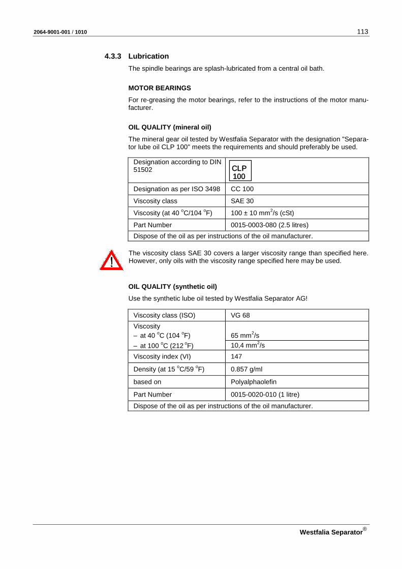
2064-9001-001 / 1010 113
Westfalia Separator®
4.3.3 Lubrication The spindle bearings are splash-lubricated from a central oil bath.
MOTOR BEARINGS
For re-greasing the motor bearings, refer to the instructions of the motor manu-facturer.
OIL QUALITY (mineral oil)
The mineral gear oil tested by Westfalia Separator with the designation "Separa-tor lube oil CLP 100" meets the requirements and should preferably be used.
Designation according to DIN 51502
CLP 100
Designation as per ISO 3498 CC 100
Viscosity class SAE 30
Viscosity (at 40 oC/104 oF) 100 ± 10 mm2/s (cSt)
Part Number 0015-0003-080 (2.5 litres) Dispose of the oil as per instructions of the oil manufacturer.
The viscosity class SAE 30 covers a larger viscosity range than specified here. However, only oils with the viscosity range specified here may be used.
OIL QUALITY (synthetic oil)
Use the synthetic lube oil tested by Westfalia Separator AG!
Viscosity class (ISO) VG 68 Viscosity – at 40 oC (104 oF) 65 mm2/s – at 100 oC (212 oF) 10,4 mm2/s Viscosity index (VI) 147
Density (at 15 oC/59 oF) 0.857 g/ml
based on Polyalphaolefin
Part Number 0015-0020-010 (1 litre)
Dispose of the oil as per instructions of the oil manufacturer.

114 2064-9001-001 / 1010
Westfalia Separator®
OIL QUANTITY
IMPORTANT: Do not forget to top up the oil in good time!
Filling in oil
Fill the drive with oil before commis-sioning the separator.
• Unscrew the screw plug and • fill in oil through the charge hole.
Filling quantity approx. 2.5 litres
Fig. 112
Oil level IMPORTANT: • Check the oil level only when the
separator is at standstill. • The oil level must never drop below
the lower third of the sight glass dur-ing operation.
1 Maximum oil level 2 Minimum oil level
Fig. 113
Minimum oil level (at separator standstill)
approx. up to lower third of sight glass
Maximum oil level (at separator standstill)
up to middle of sight glass
OIL CHECK
• Check the oil level every week!
• From time to time undo the oil drain screw and check whether there is water in the oil bath. When the oil exhibits a milky colouring (emulsification), the oil must be changed immediately.
OIL CHANGE
• Change oil after about – 4000 operating hours or 6 months at the latest (mineral oil). – 8000 operating hours or 1 year at the latest (synthetic oil).
• Clean sight glass.

2064-9001-001 / 1010 115
Westfalia Separator®
NNoottee NNootteess
NNoottiizzeenn AAnnoottaacciioonneess ДДлляя ззааппииссеейй MMuuiissttiiiinnppaannoott ΣΣηημμεειιώώσσεειιςς
NNoottaatteerr NNootteess NNoottee
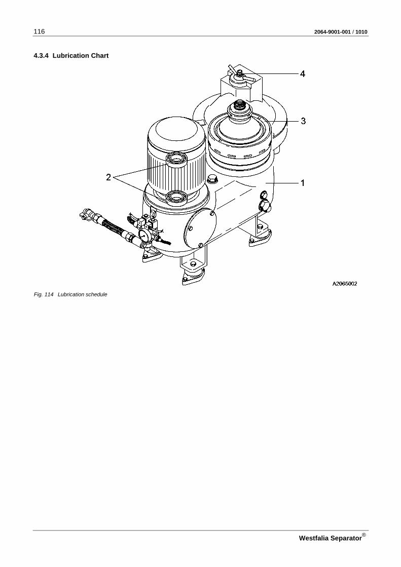
116 2064-9001-001 / 1010
Westfalia Separator®
4.3.4 Lubrication Chart
Fig. 114 Lubrication schedule
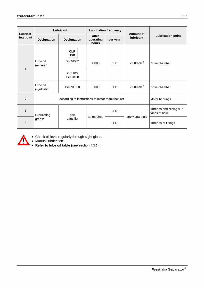
2064-9001-001 / 1010 117
Westfalia Separator®
Lubricat-ing point
Lubricant Lubrication frequency Amount of lubricant Lubrication point
Designation Designation after
operating hours
per year
1
Lube oil (mineral)
DIN 51502
CLP 100
4 000 2 x 2 500 cm3 Drive chamber
CC 100 ISO 3498
Lube oil (synthetic)
ISO VG 68 8 000 1 x 2 500 cm3 Drive chamber
2 according to instructions of motor manufacturer Motor bearings
3 Lubricating grease
see parts list as required
2 x
apply sparingly
Threads and sliding sur-faces of bowl
4 1 x Threads of fittings
• Check oil level regularly through sight glass. • Manual lubrication • Refer to lube oil table (see section 4.3.5):
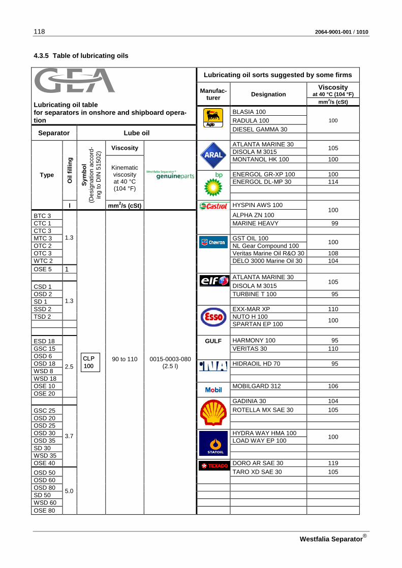
118 2064-9001-001 / 1010
Westfalia Separator®
4.3.5 Table of lubricating oils
Lubricating oil table for separators in onshore and shipboard opera-tion
Lubricating oil sorts suggested by some firms
Manufac-turer Designation
Viscosity at 40 °C (104 °F)
mm2/s (cSt)
BLASIA 100
100 RADULA 100
Separator Lube oil DIESEL GAMMA 30
Type
Oil
fillin
g
Sym
bol
(Des
igna
tion
acco
rd-
ing
to D
IN 5
1502
) Viscosity
ATLANTA MARINE 30 105 DISOLA M 3015
Kinematic viscosity at 40 °C (104 °F)
MONTANOL HK 100 100
ENERGOL GR-XP 100 100 ENERGOL DL-MP 30 114
l
mm2/s (cSt)
HYSPIN AWS 100 100
BTC 3
1.3
CLP 100
90 to 110
0015-0003-080 (2.5 l)
ALPHA ZN 100 CTC 1 MARINE HEAVY 99 CTC 3 MTC 3
GST OIL 100 100 OTC 2 NL Gear Compound 100
OTC 3 Veritas Marine Oil R&O 30 108 WTC 2 DELO 3000 Marine Oil 30 104 OSE 5 1
ATLANTA MARINE 30
105
CSD 1
1.3
DISOLA M 3015 OSD 2 TURBINE T 100 95 SD 1 SSD 2
EXX-MAR XP 110 TSD 2 NUTO H 100 100 SPARTAN EP 100
ESD 18
2.5
GULF HARMONY 100 95 GSC 15 VERITAS 30 110 OSD 6 OSD 18
HIDRAOIL HD 70 95
WSD 8 WSD 18 OSE 10
MOBILGARD 312 106
OSE 20
GADINIA 30 104
GSC 25
3.7
ROTELLA MX SAE 30 105 OSD 20 OSD 25 OSD 30
HYDRA WAY HMA 100 100 OSD 35 LOAD WAY EP 100 SD 30 WSD 35 OSE 40
DORO AR SAE 30 119
OSD 50
5.0
TARO XD SAE 30 105 OSD 60 OSD 80 SD 50 WSD 60 OSE 80
2064-9001-001 / 1010 119
Westfalia Separator®
4.3.6 Comments on table of lubricating oils for separators from GEA Westfalia Separator
Faultless functioning of separators very much depends on the proper type of lubricating oil used, since a high grade oil, selected to meet all service requirements, will minimize the wear, thus extending the ser-vice life and increasing the operating safety. For the lubrication of our separators we recommend to use the oils specified by us since continuous qual-ity checks are performed by GEA Westfalia Separator. Oils proposed from some firms are not subjected to these tests. Therefore, GEA Westfalia Separator cannot give a performance guarantee for those oils. Be sure to select only high grade solvent refined products. The specified oil types meet the requirements according to DIN. Under unfavourable operating condi-tions, e.g. high temperatures, the quality of the oils may be insufficient so that more efficient oils, e.g. synthetic oils, must be used. If necessary, consult GEA Westfalia Separator. For the different separator types and oil types the viscosity ranges are specified in the table of lubricating oils. The operating temperature of the separator exceeds normally 80 oC (176 oF). At those temperatures some oils age quickly, so that they have to be changed prematurely. Be sure not to use lubricating oils with viscosities lower than those specified in the table. Due to the pos-sibility of the oil film breaking down, oil of too low a viscosity will give insufficient lubrication, resulting in increased wear. However, oils with a slightly higher viscosity than specified may be used. Bear in mind that the viscosity groups SAE 30, 40 and 50 (SAE = Society of Automotive Engineers) cover larger viscosity ranges and be sure to select lubricating oils with viscosities not lower than the minimum values of the viscosity ranges restricted for the different separator types.

120 2064-9001-001 / 1010
Westfalia Separator®
4.4 Bowl
Fig. 115 Exploded view of the bowl and centripetal pump

2064-9001-001 / 1010 121
Westfalia Separator®
Pos. Designation Dimensions
20 (1) Bowl bottom, compl. 30 Gasket 40 Piston guide ring 50 (2) Water chamber bottom 60 Gasket 70 Gasket 80 Allen screw ISO 4762 – M 8 x 16 – A4-80 90 Annular piston
100 Gasket 110 Gasket 120 Closing chamber bottom 130 Gasket 140 Gasket 150 Gasket 180 Sliding piston 200 Gasket 210 (1) Distributor 220 Disk stack, complete 230 Separating disk 240 (1) Bowl top 250 Gasket 260 Gasket 290 Threaded pin ISO 4026 - M 10 x 10 -1.4571 310 Gasket 320 Centripetal pump chamber
cover
330 Centripetal pump chamber cover
340 Lock ring 350 Spindle screw: 360 Gasket 510 Centripetal pump, compl. 520 Gasket 530 Sensing liquid pump 540 Gasket 550 Spacer ring 560 Gasket 570 Gasket
(1) IMPORTANT: This part can only be replaced by a WS service specialist!
The complete bowl must be re-balanced in one of our authorized workshops or in the manufacturer’s plant.
(2) IMPORTANT: This part can only be replaced by a WS service specialist! A vibration check must be carried out on the machine by a WS service specialist.

122 2064-9001-001 / 1010
Westfalia Separator®
4.4.1 Dismantling the bowl • Switch off the main switch and lock it.
CAUTION: Danger to life through high-speed rotating separator parts! • Do not loosen any part of the separator before the bowl has come to a stand-
still. – The run-down time of the bowl is 45 minutes after switching off the motor. – Bowl standstill is indicated by standstill of the drive belt.
Standstill of drive belt
• Shine a torch through the frame sight glass..
• Visually check that the drive belt is no longer moving.
Fig. 116
When the sight glass is turbid: • Unscrew the sight glass, • shine a torch through the sight glass opening in the frame!
CAUTION: Danger of injury through rotating drive belt! • Check ONLY visually that the drive belt is no longer moving.
– Do NOT touch the drive belt through the sight glass opening in the frame!
• Clean the sight glass and screw it back in.
CAUTION: Danger to life through high-speed rotating separator parts!
In the case of torn or defective drive belts or if the belts have come off: • Do not loosen any part of the separator before the bowl has come to a stand-
still. • Be sure to observe the run-down time of 90 minutes until dismantling the
separator!
CAUTION: Danger of injury through very hot separator parts! When carrying out maintenance work, there is a danger of injury through hot separator parts (separating temperatures of 70 to 100 oC(158 – 212 °F)).
CAUTION: Danger to life and limb through electric current! There might be residual voltage!
In the case of motors with space heaters, residual voltages in the motor terminal box are possible despite switched off main switch. Prior to working on the motor: • Refer to the motor nameplate. • Refer to the motor instruction manual. • Take adequate preventive measures according to the national provisions (in
Germany in accordance with the rules and regulations of the VDE (Verband Deutscher Elektrotechnik/ Association of German Electrical Engineering) or of the local electric power company.
• Any work on the motor may be carried out by an authorized electrician only.

2064-9001-001 / 1010 123
Westfalia Separator®
• Avoid damage to bowl parts when fitting and removing by – precise positioning,
– no diagonal pull! – selecting the low lifting speed of the hoist.
CAUTION: Use appropriate lifting devices to prevent accidents! • Use suitably rated, intact hoists.
CAUTION: Danger to life when transporting heavy parts! • Do NOT step under hanging load.
CAUTION: Avoid accidents by using undamaged, complete tools! • Use tools only for their intended use!
– For special tools, see section 4.14 or spare parts catalog. – For standard tools, see section 4.13.
• Do not use force when removing or fitting parts.
• Treat all bowl parts – gently. – Always set them down on a rubber mat or a wooden pallet.
CAUTION: Danger of imbalance! If an installation is equipped with several separators: • Do not interchange parts from different bowls.
The bowl parts are marked with the serial number of the machine or the last three digits of the serial number.
CAUTION: • Certain bowl parts (see sect. 4.4)
may be pre-assembled and bal-anced only by specialists from Westfalia Separator or in work-shops authorized by Westfalia Separator. Unqualified balancing can lead to dangerous operating states (vi-brations) and destruction of the separator with danger to life.
Fig. 117

124 2064-9001-001 / 1010
Westfalia Separator®
Hinging up the hood
• Unscrew filling and displacement water line 1.
Fig. 118
• Unscrew handle connection piece 1 by lightly hammering with a mallet (left-hand thread); at the same time
• hold the centripetal pump with offset screwdriver 2.
Fig. 119
• Remove handle connection piece 1.
Fig. 120

2064-9001-001 / 1010 125
Westfalia Separator®
• Unscrew three hex head screws with their washers.
Fig. 121
• Hinge up the hood. CAUTION: Danger of injury by in-correct hinging up of the hood! • The stirrup must register properly.
Fig. 122
If necessary (see section 4.3.1):
• Take gasket 1 out of the upper sec-tion of the frame.
Fig. 123
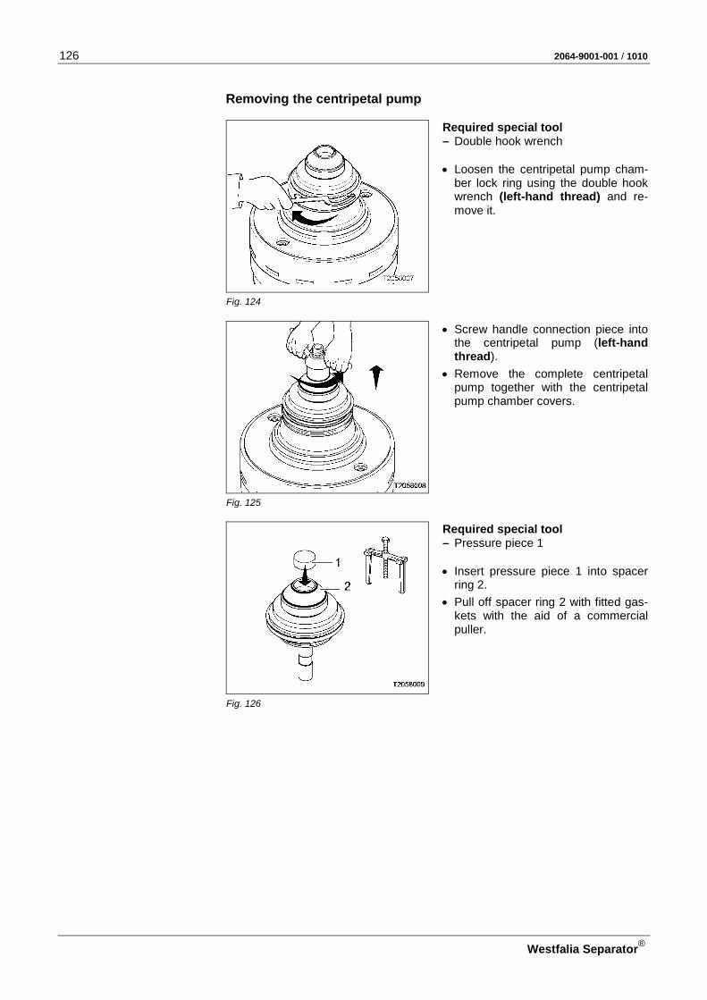
126 2064-9001-001 / 1010
Westfalia Separator®
Removing the centripetal pump
Required special tool – Double hook wrench • Loosen the centripetal pump cham-
ber lock ring using the double hook wrench (left-hand thread) and re-move it.
Fig. 124
• Screw handle connection piece into the centripetal pump (left-hand thread).
• Remove the complete centripetal pump together with the centripetal pump chamber covers.
Fig. 125
Required special tool – Pressure piece 1 • Insert pressure piece 1 into spacer
ring 2.
• Pull off spacer ring 2 with fitted gas-kets with the aid of a commercial puller.
Fig. 126

2064-9001-001 / 1010 127
Westfalia Separator®
• Remove the following parts if nec-essary: – centripetal pump chamber cover
1, – sensing liquid pump 2 with in-
serted gaskets, – centripetal pump chamber cover 4
with gaskets 3 and 5, – centripetal pump 6 with inserted
gasket.
Fig. 127
Lifting out the bowl
Required special tool – Socket wrench 1 • Unscrew the spindle screw (with
inserted gasket) with socket wrench 1 and a commercially available rat-chet wrench (left-hand thread) and remove it.
Fig. 128
Required special tool – Eye bolt 1 Bolt unit 1 comprises ring nut, hexagon nuts, and bolt. CAUTION: Avoid accidents by using undamaged and complete tools! The ring nut and the upper hexagon nut must always be screwed into the bolt and be secured with Loctite 275.
Fig. 129

128 2064-9001-001 / 1010
Westfalia Separator®
• Unscrew hexagon nut 2. • Screw eye bolt 1 into the bowl bot-
tom.
• Press off the bowl from the spindle cone by at least 10 mm.
Fig. 130
• CAUTION: Danger to life when transporting heavy parts! – Do NOT step under hanging load.
• Lift the bowl out of the frame with the aid of a hoist.
• Set the bowl down on a rubber mat or a wooden pallet for further dis-mantling.
Fig. 131
Compressing the disk stack
Required special tools Compressing device – Eye bolt 1 – Bell-shaped piece 3 • Grease the contact surface of bell-
shaped piece 3 (see chapter 4.3.4). • Place bell-shaped piece 3 on the
bowl top. • Unscrew hexagon nut 2 • Screw eye bolt 1 into the bowl bot-
tom. Fig. 132
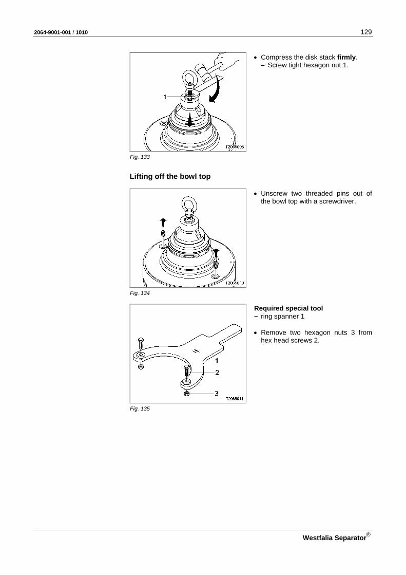
2064-9001-001 / 1010 129
Westfalia Separator®
• Compress the disk stack firmly. – Screw tight hexagon nut 1.
Fig. 133
Lifting off the bowl top
• Unscrew two threaded pins out of the bowl top with a screwdriver.
Fig. 134
Required special tool – ring spanner 1 • Remove two hexagon nuts 3 from
hex head screws 2.
Fig. 135
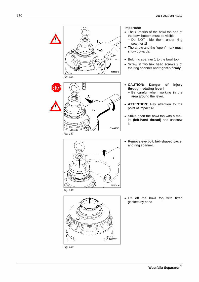
130 2064-9001-001 / 1010
Westfalia Separator®
Important: • The O-marks of the bowl top and of
the bowl bottom must be visible. – Do NOT hide them under ring
spanner 1! • The arrow and the "open" mark must
show upwards. • Bolt ring spanner 1 to the bowl top.
• Screw in two hex head screws 2 of the ring spanner and tighten firmly.
Fig. 136
• CAUTION: Danger of injury through rotating lever! – Be careful when working in the
area around the lever. • ATTENTION: Pay attention to the
point of impact A!
• Strike open the bowl top with a mal-let (left-hand thread) and unscrew it.
Fig. 137
• Remove eye bolt, bell-shaped piece, and ring spanner.
Fig. 138
• Lift off the bowl top with fitted gaskets by hand.
Fig. 139
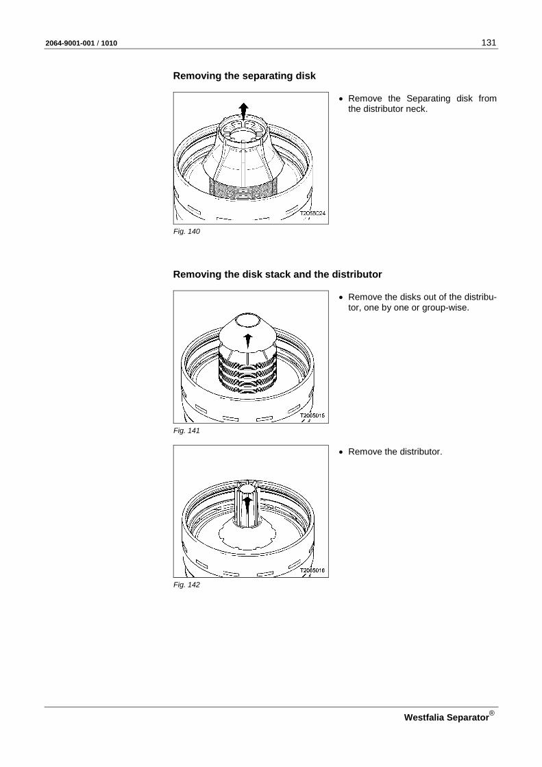
2064-9001-001 / 1010 131
Westfalia Separator®
Removing the separating disk
• Remove the Separating disk from the distributor neck.
Fig. 140
Removing the disk stack and the distributor
• Remove the disks out of the distribu-tor, one by one or group-wise.
Fig. 141
• Remove the distributor.
Fig. 142

132 2064-9001-001 / 1010
Westfalia Separator®
Removing the sliding piston
• Insert the spindle screw into the hub.
Fig. 143
Required special tools – Eye bolt 1 – Bell-shaped piece 2 • Unscrew hexagon nut 3
Fig. 144
• Assemble eye bolt 1 and bell-shaped piece 2: – Screw eye bolt 1 into bell-shaped
piece 2 – Screw eye bolt 1 into hexagon nut
3 by approx. 20 mm.
Fig. 145

2064-9001-001 / 1010 133
Westfalia Separator®
• Grease the thread of sliding piston 1 (see chapter 4.3.4).
• Screw the bell-shaped piece with fitted eye bolt into the thread of the sliding piston.
Fig. 146
Required special tool – Socket wrench 1 • Press off the sliding piston from the
bowl bottom by turning the socket wrench clockwise.
Fig. 147
• Remove the sliding piston (with fitted gasket) with bell-shaped piece and eye bolt.
• Remove the bell-shaped piece and the eye bolt.
Fig. 148

134 2064-9001-001 / 1010
Westfalia Separator®
Removing the annular piston and the closing chamber bottom
Required special tool – Socket wrench 1 • Unscrew the Allen screws holding
the bowl bottom and the closing-chamber bottom together.
Fig. 149
Required special tools – Eye bolt 1 – Bell-shaped piece 2 – Assembling device 3 • Unscrew hexagon nut 4
Fig. 150
• Assemble eye bolt 1 and bell-shaped piece 2: – Screw eye bolt 1 into bell-shaped
piece 2 – Screw eye bolts 1 into hexagon
nut 3 by approx. 20 mm.
Fig. 151

2064-9001-001 / 1010 135
Westfalia Separator®
• Place the bell-shaped piece with fitted eye bolt into the bowl bottom.
• Fit assembling device 3 onto the bell-shaped piece.
• Loosen three Allen screws 4 using the ratchet wrench (with extension and socket).
• Slip three disks 5 of the assembling device towards the periphery, under the rim of annular piston 6.
• Make sure that disks 5 are properly positioned in the mounting groove of the annular piston.
• Firmly re-tighten Allen screws 4. Fig. 152
• Force off closing chamber bottom 3 together with annular piston 4 by turning wrench 5 clockwise.
Fig. 153
• Remove closing chamber bottom 3 and annular piston 4 (with fitted gaskets) with the bell-shaped piece and the eye bolt.
• Remove the bell-shaped piece and the eye bolt.
Fig. 154
• Separate annular piston 1 from clos-ing chamber bottom 2 by tapping with a mallet – as illustrated.
Fig. 155
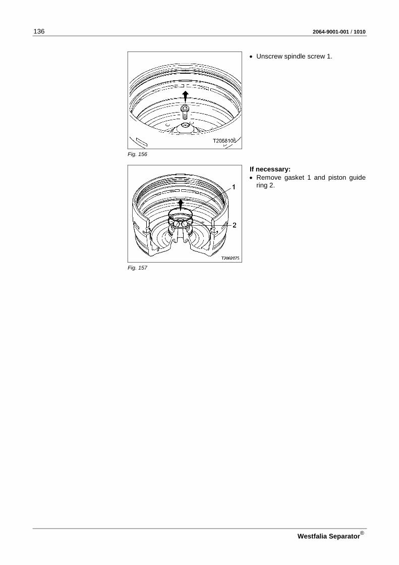
136 2064-9001-001 / 1010
Westfalia Separator®
• Unscrew spindle screw 1.
Fig. 156
If necessary: • Remove gasket 1 and piston guide
ring 2.
Fig. 157
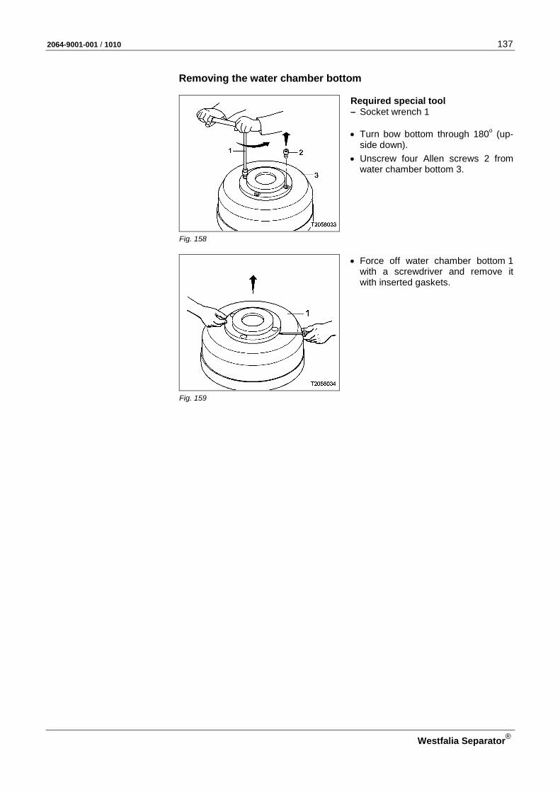
2064-9001-001 / 1010 137
Westfalia Separator®
Removing the water chamber bottom
Required special tool – Socket wrench 1 • Turn bow bottom through 180o (up-
side down).
• Unscrew four Allen screws 2 from water chamber bottom 3.
Fig. 158
• Force off water chamber bottom 1 with a screwdriver and remove it with inserted gaskets.
Fig. 159
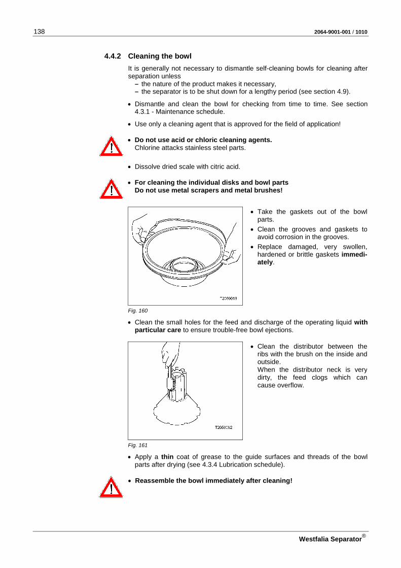
138 2064-9001-001 / 1010
Westfalia Separator®
4.4.2 Cleaning the bowl It is generally not necessary to dismantle self-cleaning bowls for cleaning after separation unless
– the nature of the product makes it necessary, – the separator is to be shut down for a lengthy period (see section 4.9).
• Dismantle and clean the bowl for checking from time to time. See section 4.3.1 - Maintenance schedule.
• Use only a cleaning agent that is approved for the field of application!
• Do not use acid or chloric cleaning agents. Chlorine attacks stainless steel parts.
• Dissolve dried scale with citric acid.
• For cleaning the individual disks and bowl parts Do not use metal scrapers and metal brushes!
• Take the gaskets out of the bowl parts.
• Clean the grooves and gaskets to avoid corrosion in the grooves.
• Replace damaged, very swollen, hardened or brittle gaskets immedi-ately.
Fig. 160
• Clean the small holes for the feed and discharge of the operating liquid with particular care to ensure trouble-free bowl ejections.
• Clean the distributor between the ribs with the brush on the inside and outside. When the distributor neck is very dirty, the feed clogs which can cause overflow.
Fig. 161
• Apply a thin coat of grease to the guide surfaces and threads of the bowl parts after drying (see 4.3.4 Lubrication schedule).
• Reassemble the bowl immediately after cleaning!

2064-9001-001 / 1010 139
Westfalia Separator®
4.4.3 Cleaning the frame
CAUTION: Danger to life through electrical components! • Never rinse off the motor with a direct water jet.
• Use only a cleaning agent that is approved for the field of application!
ATTENTION! • Do not use acid or chloric cleaning agents.
Chlorine attacks stainless steel parts.
• Dissolve dried scale with citric acid.
• Clean the inside of the upper section of the frame from time to time: To do this: – Refer to the maintenance schedule (section 4.3.1),
– dismantle the bowl (section 4.4.1).
ATTENTION: Escaping cleaning liquid! When the bowl has been removed, no cleaning liquid must spill onto the drive belt via the spindle.
• Make sure that protective cap 2 and spindle cap 1 with inserted gasket are installed.
Fig. 162
4.4.4 Cleaning the strainer and the operating water feeding system • The strainer and the operating water feeding system must be cleaned de-
pending on the quality of the operating water and overall load. See section 4.3.1 Maintenance schedule
• Use citric acid in case of furring.
• Thoroughly clean the parts with water.
Replacing or cleaning the filter element
CAUTION: Danger due to electrical current! • Switch off the main switch and lock it.
• Close the main valve for operating water, filling and displacement water.
CAUTION: Danger of injury through very hot separator parts! When carrying out maintenance work, there is a danger of injury through hot separator parts (separating temperatures of 70 to 100 oC (158 – 212 °F) ).
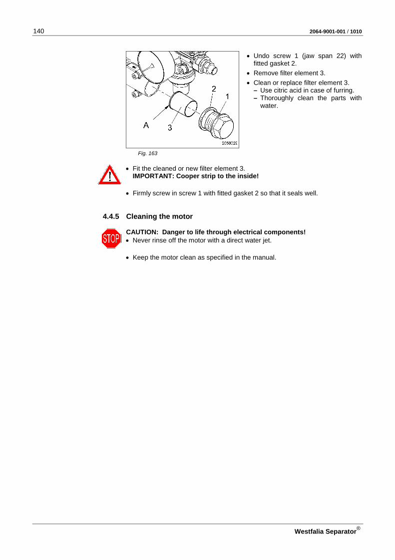
140 2064-9001-001 / 1010
Westfalia Separator®
• Undo screw 1 (jaw span 22) with fitted gasket 2.
• Remove filter element 3.
• Clean or replace filter element 3. – Use citric acid in case of furring. – Thoroughly clean the parts with
water.
Fig. 163
• Fit the cleaned or new filter element 3. IMPORTANT: Cooper strip to the inside!
• Firmly screw in screw 1 with fitted gasket 2 so that it seals well.
4.4.5 Cleaning the motor
CAUTION: Danger to life through electrical components! • Never rinse off the motor with a direct water jet.
• Keep the motor clean as specified in the manual.
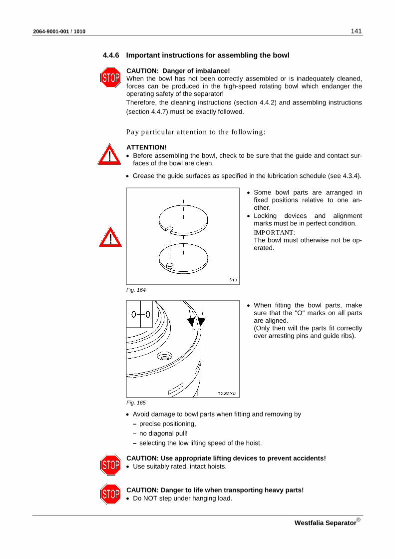
2064-9001-001 / 1010 141
Westfalia Separator®
4.4.6 Important instructions for assembling the bowl
CAUTION: Danger of imbalance! When the bowl has not been correctly assembled or is inadequately cleaned, forces can be produced in the high-speed rotating bowl which endanger the operating safety of the separator! Therefore, the cleaning instructions (section 4.4.2) and assembling instructions (section 4.4.7) must be exactly followed.
Pay particu lar a ttention to the fo llowing:
ATTENTION! • Before assembling the bowl, check to be sure that the guide and contact sur-
faces of the bowl are clean.
• Grease the guide surfaces as specified in the lubrication schedule (see 4.3.4).
• Some bowl parts are arranged in fixed positions relative to one an-other.
• Locking devices and alignment marks must be in perfect condition.
IMPORTANT: The bowl must otherwise not be op-erated.
Fig. 164
• When fitting the bowl parts, make sure that the "O" marks on all parts are aligned. (Only then will the parts fit correctly over arresting pins and guide ribs).
Fig. 165
• Avoid damage to bowl parts when fitting and removing by – precise positioning, – no diagonal pull! – selecting the low lifting speed of the hoist.
CAUTION: Use appropriate lifting devices to prevent accidents! • Use suitably rated, intact hoists.
CAUTION: Danger to life when transporting heavy parts! • Do NOT step under hanging load.

142 2064-9001-001 / 1010
Westfalia Separator®
CAUTION: Avoid accidents by using undamaged, complete tools! • Use tools only for their intended use!
– For special tools, see section 4.14 or spare parts catalog. – For standard tools, see section 4.13.
• Do not use force when removing or fitting parts.
CAUTION: Danger of imbalance! • If the plant has several separators,
be sure not to interchange parts of different bowls.
The parts are marked – with the serial number or – the last three digits of the serial
number.
Fig. 166
• Thoroughly clean the gasket grooves of the individual bowl parts and apply a thin coat of grease.
• After fitting check that – the gaskets are not twisted, – the gaskets are evenly positioned
in the groove.
Fig. 167
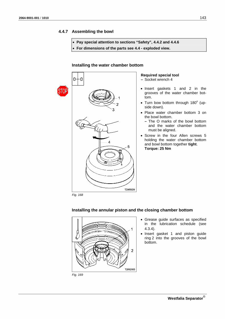
2064-9001-001 / 1010 143
Westfalia Separator®
4.4.7 Assembling the bowl
• Pay special attention to sections “Safety”, 4.4.2 and 4.4.6
• For dimensions of the parts see 4.4 - exploded view.
Installing the water chamber bottom
Required special tool – Socket wrench 4 • Insert gaskets 1 and 2 in the
grooves of the water chamber bot-tom.
• Turn bow bottom through 180o (up-side down).
• Place water chamber bottom 3 on the bowl bottom. – The O marks of the bowl bottom
and the water chamber bottom must be aligned.
• Screw in the four Allen screws 5 holding the water chamber bottom and bowl bottom together tight. Torque: 25 Nm
Fig. 168
Installing the annular piston and the closing chamber bottom
• Grease guide surfaces as specified in the lubrication schedule (see 4.3.4).
• Insert gasket 1 and piston guide ring 2 into the grooves of the bowl bottom.
Fig. 169
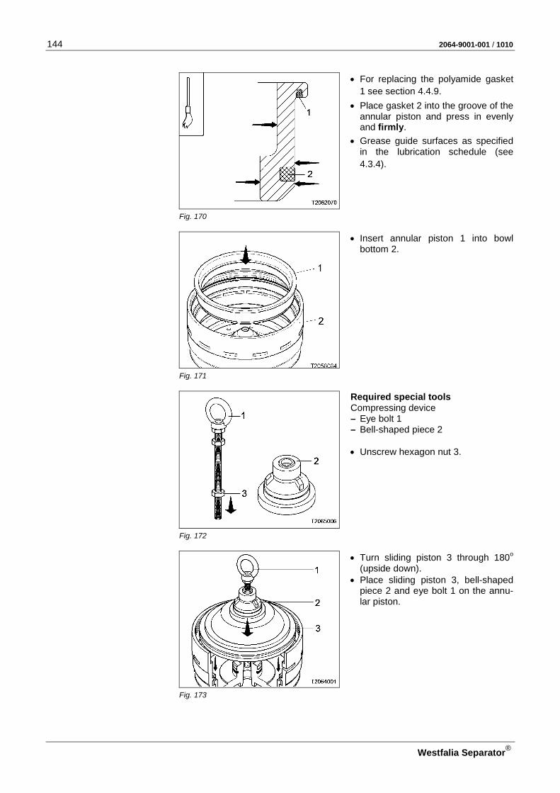
144 2064-9001-001 / 1010
Westfalia Separator®
• For replacing the polyamide gasket 1 see section 4.4.9.
• Place gasket 2 into the groove of the annular piston and press in evenly and firmly.
• Grease guide surfaces as specified in the lubrication schedule (see 4.3.4).
Fig. 170
• Insert annular piston 1 into bowl bottom 2.
Fig. 171
Required special tools Compressing device – Eye bolt 1 – Bell-shaped piece 2 • Unscrew hexagon nut 3.
Fig. 172
• Turn sliding piston 3 through 180o (upside down).
• Place sliding piston 3, bell-shaped piece 2 and eye bolt 1 on the annu-lar piston.
Fig. 173
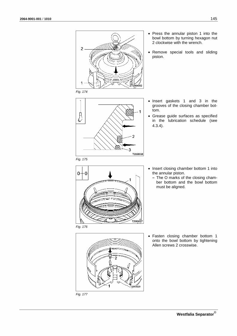
2064-9001-001 / 1010 145
Westfalia Separator®
• Press the annular piston 1 into the bowl bottom by turning hexagon nut 2 clockwise with the wrench.
• Remove special tools and sliding
piston.
Fig. 174
• Insert gaskets 1 and 3 in the grooves of the closing chamber bot-tom.
• Grease guide surfaces as specified in the lubrication schedule (see 4.3.4).
Fig. 175
• Insert closing chamber bottom 1 into the annular piston. – The O marks of the closing cham-
ber bottom and the bowl bottom must be aligned.
Fig. 176
• Fasten closing chamber bottom 1 onto the bowl bottom by tightening Allen screws 2 crosswise.
Fig. 177
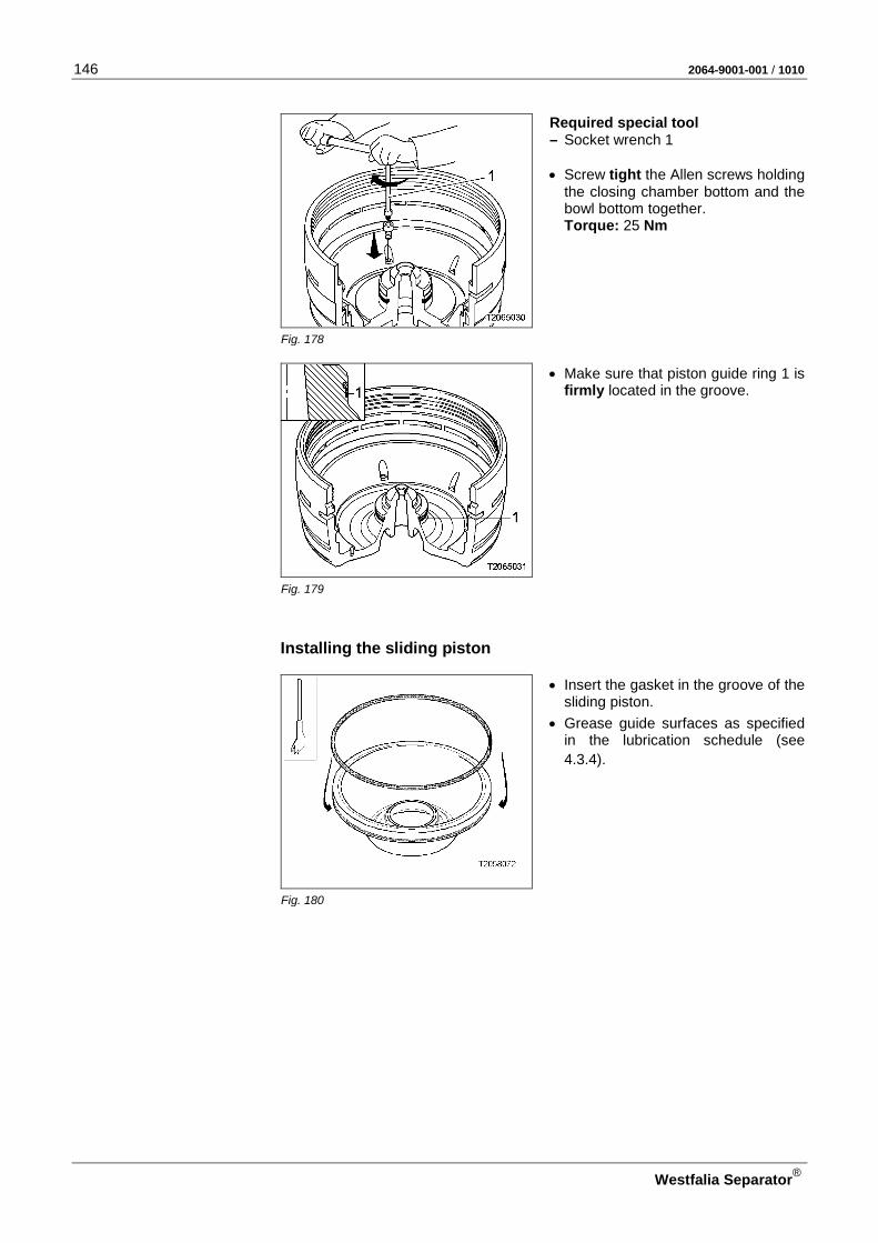
146 2064-9001-001 / 1010
Westfalia Separator®
Required special tool – Socket wrench 1 • Screw tight the Allen screws holding
the closing chamber bottom and the bowl bottom together. Torque: 25 Nm
Fig. 178
• Make sure that piston guide ring 1 is firmly located in the groove.
Fig. 179
Installing the sliding piston
• Insert the gasket in the groove of the sliding piston.
• Grease guide surfaces as specified in the lubrication schedule (see 4.3.4).
Fig. 180
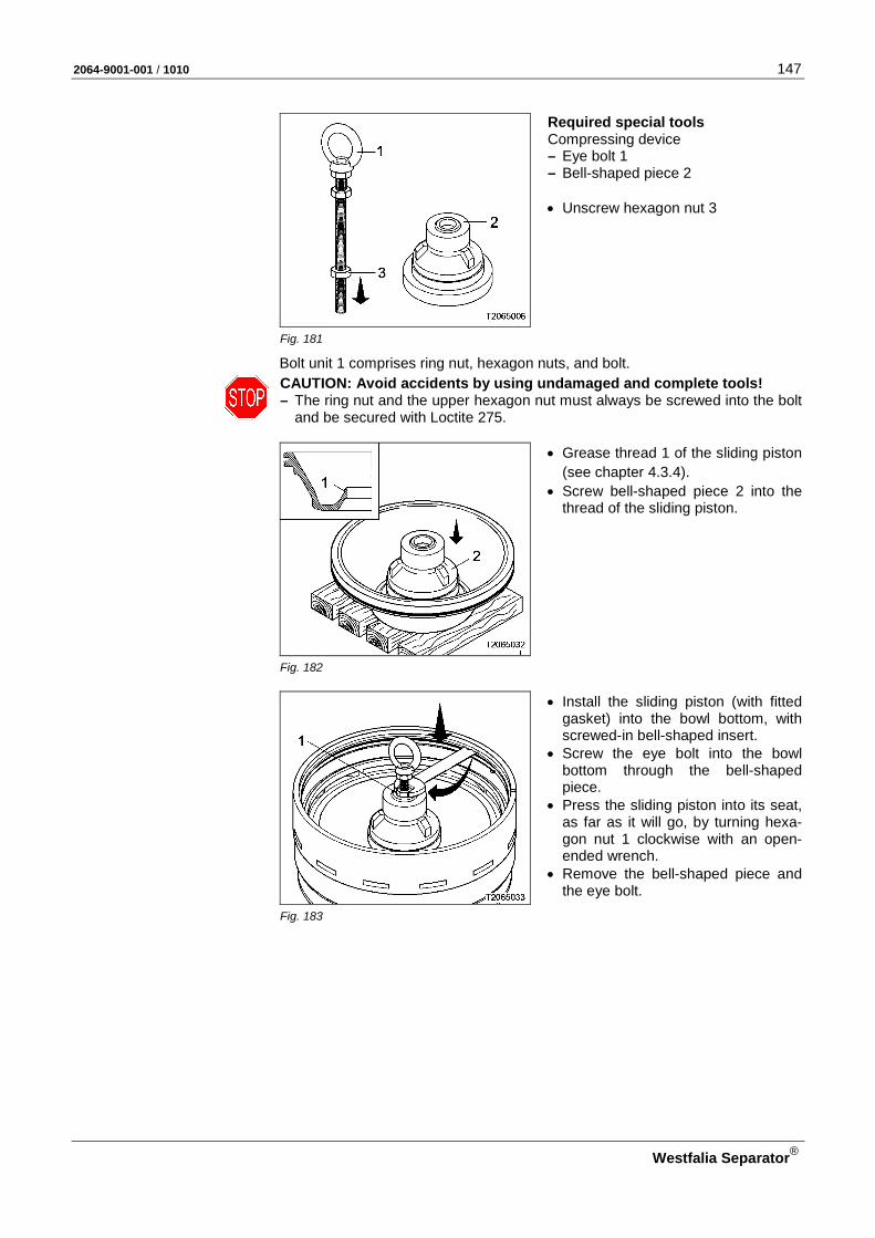
2064-9001-001 / 1010 147
Westfalia Separator®
Required special tools Compressing device – Eye bolt 1 – Bell-shaped piece 2 • Unscrew hexagon nut 3
Fig. 181
Bolt unit 1 comprises ring nut, hexagon nuts, and bolt.
CAUTION: Avoid accidents by using undamaged and complete tools! – The ring nut and the upper hexagon nut must always be screwed into the bolt
and be secured with Loctite 275.
• Grease thread 1 of the sliding piston (see chapter 4.3.4).
• Screw bell-shaped piece 2 into the thread of the sliding piston.
Fig. 182
• Install the sliding piston (with fitted gasket) into the bowl bottom, with screwed-in bell-shaped insert.
• Screw the eye bolt into the bowl bottom through the bell-shaped piece.
• Press the sliding piston into its seat, as far as it will go, by turning hexa-gon nut 1 clockwise with an open-ended wrench.
• Remove the bell-shaped piece and the eye bolt.
Fig. 183

148 2064-9001-001 / 1010
Westfalia Separator®
Installing the distributor and the disk stack
• Insert the distributor into the sliding piston. – Pay attention to correct position-
ing. – The "O" marks must be aligned.
Fig. 184
ATTENTION: Pay attention for cor-rect total number of disks! It is marked on the blind disk, e.g. 84/1: – Total number of disks A and B = 84
(number of disks with spacers A + number of blind disks B)
– Number of blind disks B = 1
Fig. 185
ATTENTION: The last disks must be properly located in the guide ribs of the distributor! • Carefully stack the disks on the dis-
tributor neck, one by one or group-wise .
Fig. 186
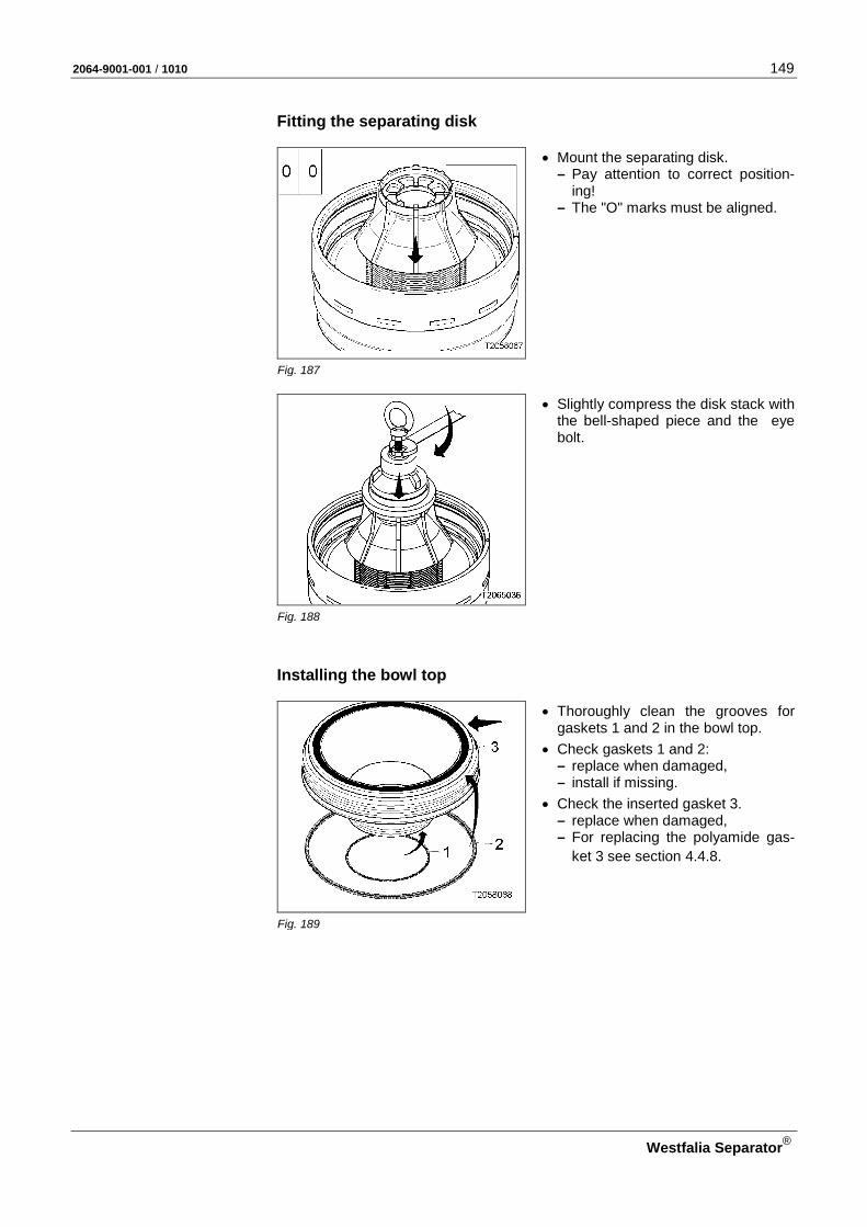
2064-9001-001 / 1010 149
Westfalia Separator®
Fitting the separating disk
• Mount the separating disk. – Pay attention to correct position-
ing! – The "O" marks must be aligned.
Fig. 187
• Slightly compress the disk stack with the bell-shaped piece and the eye bolt.
Fig. 188
Installing the bowl top
• Thoroughly clean the grooves for gaskets 1 and 2 in the bowl top.
• Check gaskets 1 and 2: – replace when damaged, – install if missing.
• Check the inserted gasket 3. – replace when damaged, – For replacing the polyamide gas-
ket 3 see section 4.4.8.
Fig. 189

150 2064-9001-001 / 1010
Westfalia Separator®
ATTENTION: Prevent seizing of threads! • The following parts must be carefully
cleaned, wiped dry and greased in accordance with the lubrication schedule (see 4.3.4). – threads and guide surfaces of
bowl bottom and bowl top – contact surfaces of bowl top and
sliding piston
Fig. 190
Required special tool – ring spanner 1 • Remove two hexagon nuts 3 from
hex head screws 2. Important: • If threaded pins are screwed into the
bowl top, undo them with a screw-driver.
• The O mark of the bowl top must be visible. – Do NOT hide them under ring
spanner 1! • The arrow and the "open" mark must
show upwards.
Fig. 191
• Bolt ring spanner 1 to the bowl top.
– Screw in two hex head screws 2 of the ring spanner and tighten firmly.
• Screw the bowl top by hand into the bowl bottom as far as it will go (left-hand thread).
Fig. 192
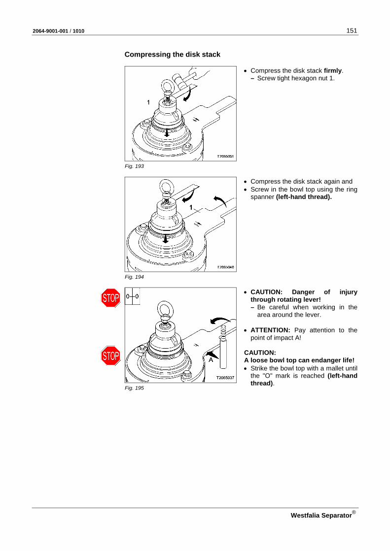
2064-9001-001 / 1010 151
Westfalia Separator®
Compressing the disk stack
• Compress the disk stack firmly. – Screw tight hexagon nut 1.
Fig. 193
• Compress the disk stack again and • Screw in the bowl top using the ring
spanner (left-hand thread).
Fig. 194
• CAUTION: Danger of injury through rotating lever! – Be careful when working in the
area around the lever. • ATTENTION: Pay attention to the
point of impact A! CAUTION: A loose bowl top can endanger life! • Strike the bowl top with a mallet until
the "O" mark is reached (left-hand thread).
Fig. 195

152 2064-9001-001 / 1010
Westfalia Separator®
• Remove eye bolt, bell-shaped piece, and ring spanner.
Fig. 196
• Screw in two threaded pins using a screwdriver.
Fig. 197
Installing the complete bowl and the centripetal pump
• Clean and wipe dry the spindle cone with a suitable cloth.
ATTENTION: Do not grease the conical parts!
Fig. 198

2064-9001-001 / 1010 153
Westfalia Separator®
Required special tool – Eye bolt 1 • Unscrew hexagon nut 2 • Screw eye bolt 1 into the bowl bot-
tom.
Fig. 199
• Turn bowl through 90o (opposite the fitting position).
• Clean the bowl hub with a suitable cloth.
ATTENTION: Do not grease the bowl hub!
Fig. 200
• CAUTION: Danger to life when transporting heavy parts! – Do NOT step under hanging load.
• Carefully place the bowl using eye bolt and hoist on the spindle cone.
• Unscrew the eye bolt from the bowl bottom and remove the hoist.
Fig. 201
Required tools – Socket wrench – Torque wrench • Provide spindle screw 2 with gasket
1.
• Put spindle screw into socket wrench and screw in (left-hand thread).
Fig. 202
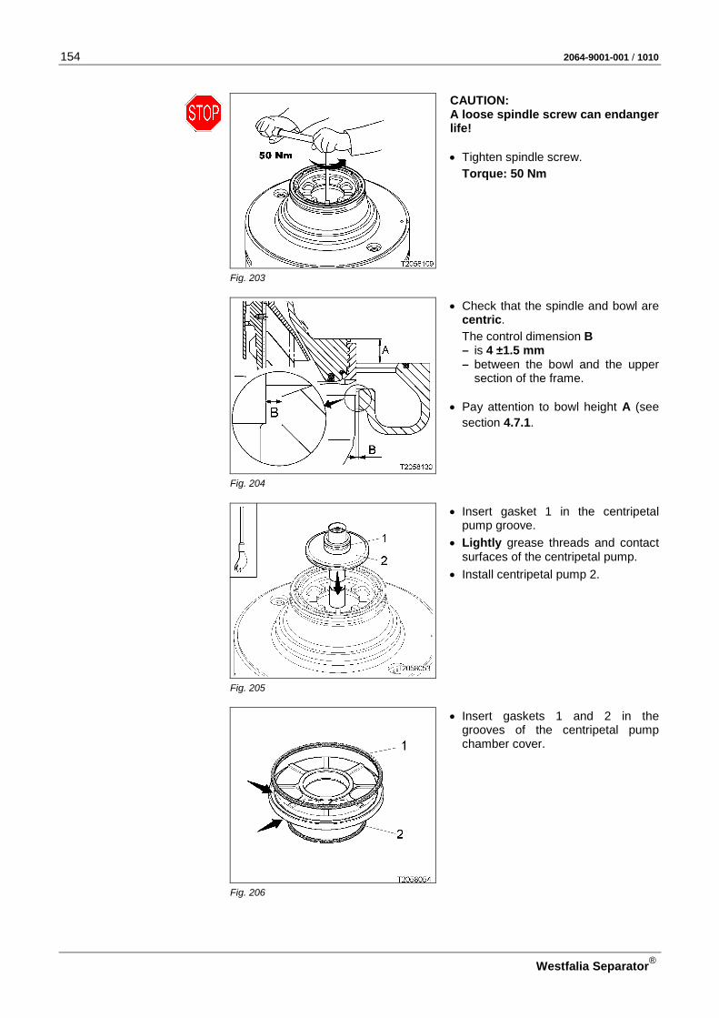
154 2064-9001-001 / 1010
Westfalia Separator®
CAUTION: A loose spindle screw can endanger life! • Tighten spindle screw.
Torque: 50 Nm
Fig. 203
• Check that the spindle and bowl are centric.
The control dimension B – is 4 ±1.5 mm – between the bowl and the upper
section of the frame. • Pay attention to bowl height A (see
section 4.7.1.
Fig. 204
• Insert gasket 1 in the centripetal pump groove.
• Lightly grease threads and contact surfaces of the centripetal pump.
• Install centripetal pump 2.
Fig. 205
• Insert gaskets 1 and 2 in the grooves of the centripetal pump chamber cover.
Fig. 206

2064-9001-001 / 1010 155
Westfalia Separator®
• Mount the centripetal pump chamber cover with fitted gaskets. – The “O” marks of the centripetal
pump chamber cover and the bowl top must be aligned.
Fig. 207
• Insert gaskets 1 and 2 in the sensing liquid pump grooves.
• Grease guide surfaces.
• Install sensing liquid pump.
Fig. 208
• Mount the centripetal pump chamber cover. – The “O” marks of the centripetal
pump chamber cover and the bowl top must be aligned.
Fig. 209
Required special tool – Double hook wrench • Grease the threads on the bowl top
and on the centripetal pump cham-ber lock ring as specified in the Lu-brication schedule (see 4.3.4).
CAUTION: A loose centripetal pump chamber lock ring can endanger life! • Screw tight the centripetal pump
chamber lock ring using the double hook wrench (left-hand thread). Fig. 210
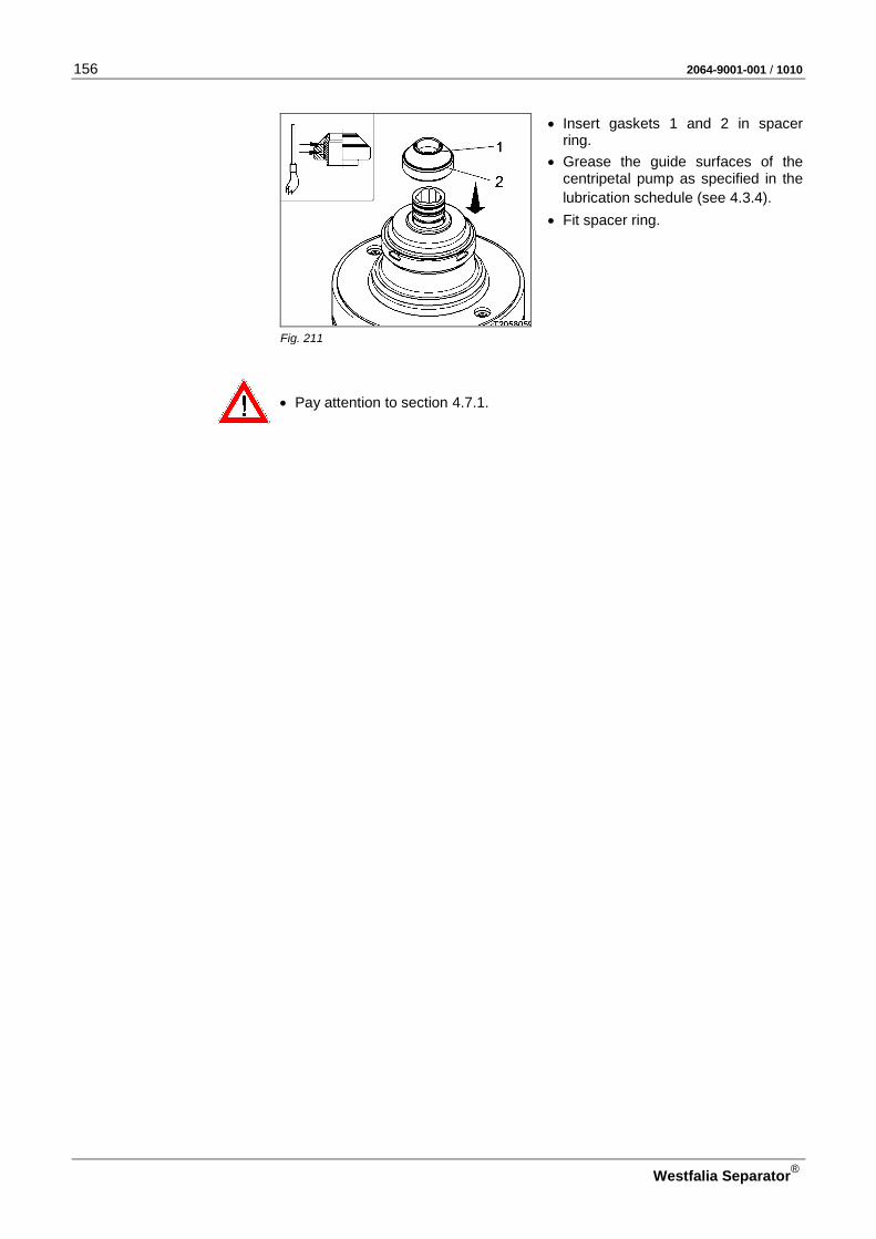
156 2064-9001-001 / 1010
Westfalia Separator®
• Insert gaskets 1 and 2 in spacer ring.
• Grease the guide surfaces of the centripetal pump as specified in the lubrication schedule (see 4.3.4).
• Fit spacer ring.
Fig. 211
• Pay attention to section 4.7.1.
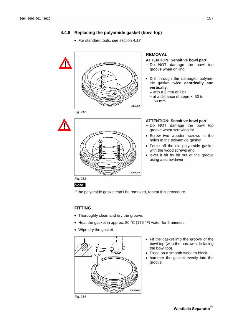
2064-9001-001 / 1010 157
Westfalia Separator®
4.4.8 Replacing the polyamide gasket (bowl top)
• For standard tools, see section 4.13.
REMOVAL
ATTENTION: Sensitive bowl part! – Do NOT damage the bowl top
groove when drilling! • Drill through the damaged polyam-
ide gasket twice centrically and vertically. – with a 2 mm drill bit – at a distance of approx. 50 to
60 mm.
Fig. 212
ATTENTION: Sensitive bowl part! – Do NOT damage the bowl top
groove when screwing in!
• Screw two wooden screws in the holes in the polyamide gasket.
• Force off the old polyamide gasket with the wood screws and
• lever it bit by bit out of the groove using a screwdriver.
Fig. 213
Note:
If the polyamide gasket can’t be removed, repeat this procedure.
FITTING • Thoroughly clean and dry the groove.
• Heat the gasket in approx. 80 oC (176 °F) water for 5 minutes.
• Wipe dry the gasket.
• Fit the gasket into the groove of the bowl top (with the narrow side facing the bowl top).
• Place on a smooth wooden block. • hammer the gasket evenly into the
groove.
Fig. 214

158 2064-9001-001 / 1010
Westfalia Separator®
• Assemble the bowl and centripetal pump and fit in the separator (see section 4.4.7 "Assembling the bowl".
• Close the hood (see section 4.5 “Closing the hood”).
• Start the separator (see section 3.3 “Starting the separator”).
ATTENTION! Do not start the program!
Only after a running time of 30 minutes • Start the program. This running time must be adhered to so that the polyamide gasket is pressed properly into the bowl top. If the separator is switched off by the program, • switch on the separator motor by pressing the start key. • Compare the starting current and starting time with the diagram (section
4.1.3) until the bowl reaches the speed specified on the separator nameplate. Note: The run-up phase of the separator motor is signalled by slow flashing of the LED in the “Status Separator” key.

2064-9001-001 / 1010 159
Westfalia Separator®
4.4.9 Replacing the polyamide gasket (bowl top)
Important: Time-consuming installation! Change the polyamide gasket only when it is damaged.
• For standard tools, see section 4.13.
REMOVAL
ATTENTION: Sensitive bowl part! – Do NOT damage the ring piston
groove when drilling! • Drill through the damaged polyam-
ide gasket twice centrically and vertically. – with a 2 mm drill bit – at a distance of approx. 50 to
60 mm.
Fig. 215
ATTENTION: Sensitive bowl part! – Do NOT damage the ring piston
groove when screwing in!
• Screw two wooden screws in the holes in the polyamide gasket.
• Force off the old polyamide gasket with the wood screws and
• lever it bit by bit out of the groove using a screwdriver.
Fig. 216
Note:
If the polyamide gasket can’t be removed, repeat this procedure.
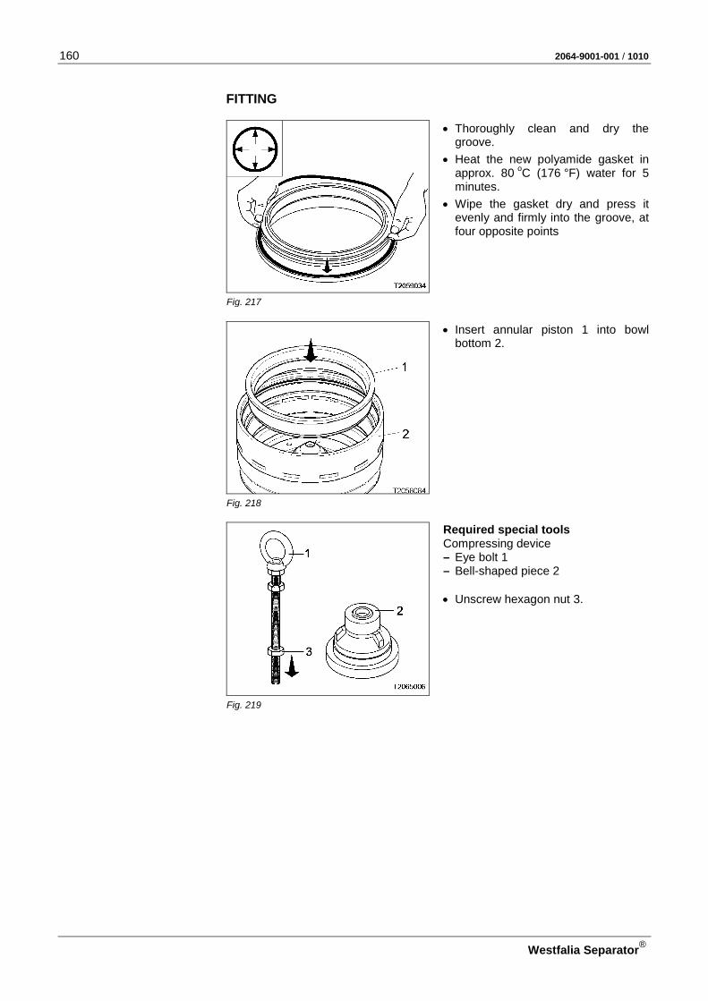
160 2064-9001-001 / 1010
Westfalia Separator®
FITTING
• Thoroughly clean and dry the groove.
• Heat the new polyamide gasket in approx. 80 oC (176 °F) water for 5 minutes.
• Wipe the gasket dry and press it evenly and firmly into the groove, at four opposite points
Fig. 217
• Insert annular piston 1 into bowl bottom 2.
Fig. 218
Required special tools Compressing device – Eye bolt 1 – Bell-shaped piece 2 • Unscrew hexagon nut 3.
Fig. 219

2064-9001-001 / 1010 161
Westfalia Separator®
• Turn sliding piston 3 through 180o (upside down).
• Place sliding piston 3, bell-shaped piece 2 and eye bolt 1 on the annu-lar piston.
Fig. 220
• Press the annular piston 1 into the bowl bottom by turning hexagon nut 2 clockwise with the wrench.
• Remove special tools and sliding
piston.
Fig. 221
• Insert gaskets 1 and 3 in the grooves of the closing chamber bot-tom.
• Grease guide surfaces as specified in the lubrication schedule (see 4.3.4).
Fig. 222
• Clamp mounting ring 1 under the rim of the closing chamber bottom.
Fig. 223

162 2064-9001-001 / 1010
Westfalia Separator®
• Insert closing chamber bottom 1 into the annular piston. – The O marks of the closing cham-
ber bottom and the bowl bottom must be aligned.
Fig. 224
• Fasten closing chamber bottom 1 onto the bowl bottom by tightening Allen screws 2 crosswise.
Fig. 225
Required special tool – Socket wrench 1 • Screw tight the Allen screws holding
the closing chamber bottom and the bowl bottom together. Torque: 25 Nm
Fig. 226
• Insert spindle screw 1 into the hub.
Fig. 227

2064-9001-001 / 1010 163
Westfalia Separator®
• Unscrew the Allen screws holding the bowl bottom and the closing-chamber bottom together.
Fig. 228
Required special tools – Eye bolt 1 – Bell-shaped piece 2 – Assembling device 3 • Unscrew hexagon nut 4.
Fig. 229
• Assemble eye bolt 1 and bell-shaped piece 2: – Screw eye bolt 1 into bell-shaped
piece 2 – Screw eye bolts 1 into hexagon
nut 3 by approx. 20 mm.
Fig. 230
• Place the bell-shaped piece with fitted eye bolt into the bowl bottom.
• Fit assembling device 3 onto the bell-shaped piece.
• Loosen three Allen screws 4 using the ratchet wrench (with extension and socket).
• Slip three disks 5 of the assembling device towards the periphery, under the rim of annular piston 6.
• Make sure that disks 5 are properly positioned in the mounting groove of the annular piston.
• Firmly re-tighten Allen screws 4. Fig. 231

164 2064-9001-001 / 1010
Westfalia Separator®
• Force off closing chamber bottom 3 together with annular piston 4 by turning wrench 5 clockwise.
Fig. 232
• Remove closing chamber bottom 3 and annular piston 4 (with fitted gas-kets) with the bell-shaped piece and the eye bolt.
• Remove the bell-shaped piece and the eye bolt.
Fig. 233
• Separate annular piston 1 from clos-ing chamber bottom 2 by tapping with a mallet – as illustrated.
• Remove the mounting ring.
Fig. 234
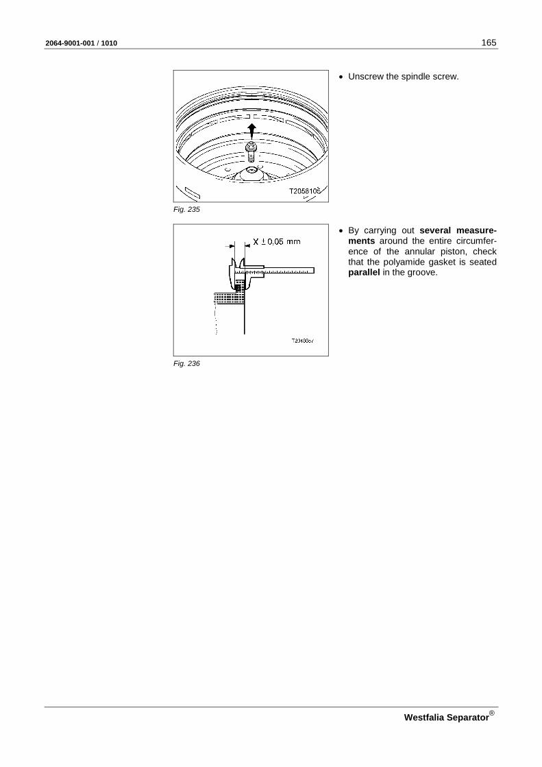
2064-9001-001 / 1010 165
Westfalia Separator®
• Unscrew the spindle screw.
Fig. 235
• By carrying out several measure-ments around the entire circumfer-ence of the annular piston, check that the polyamide gasket is seated parallel in the groove.
Fig. 236
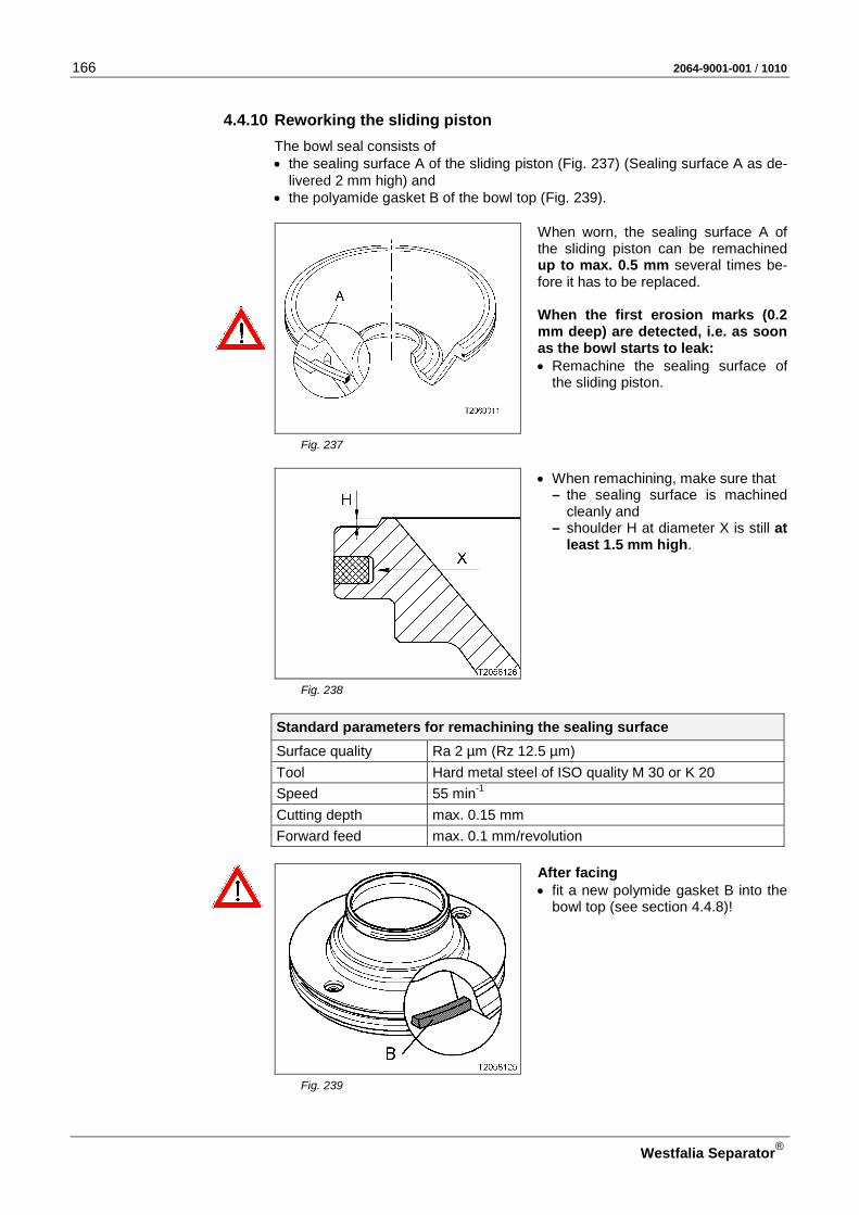
166 2064-9001-001 / 1010
Westfalia Separator®
4.4.10 Reworking the sliding piston The bowl seal consists of • the sealing surface A of the sliding piston ( Fig. 237) (Sealing surface A as de-
livered 2 mm high) and • the polyamide gasket B of the bowl top ( Fig. 239).
When worn, the sealing surface A of the sliding piston can be remachined up to max. 0.5 mm several times be-fore it has to be replaced. When the first erosion marks (0.2 mm deep) are detected, i.e. as soon as the bowl starts to leak: • Remachine the sealing surface of
the sliding piston.
Fig. 237
• When remachining, make sure that – the sealing surface is machined
cleanly and – shoulder H at diameter X is still at
least 1.5 mm high.
Fig. 238
Standard parameters for remachining the sealing surface
Surface quality Ra 2 µm (Rz 12.5 µm) Tool Hard metal steel of ISO quality M 30 or K 20 Speed 55 min-1 Cutting depth max. 0.15 mm Forward feed max. 0.1 mm/revolution
After facing • fit a new polymide gasket B into the
bowl top (see section 4.4.8)!
Fig. 239

2064-9001-001 / 1010 167
Westfalia Separator®
4.5 Closing the hood
If the gasket has been removed to keep to the service intervals: • insert a new gasket 1 in the groove
of the upper part of the frame.
Fig. 240
CAUTION: Danger of injury!
• Unlock the shackle.
• Carefully close the hood.
Fig. 241
• Screw in three hex head screws (M 12 x 30) with washers.
Fig. 242

168 2064-9001-001 / 1010
Westfalia Separator®
If the gaskets 2 have been removed to keep to the service intervals: • Provide handle connection piece 1
with new gaskets 2.
• Apply a thin coat of grease to the guide surfaces and threads of the handle connection piece as speci-fied in the lubrication schedule (see 4.3.4).
Fig. 243
Required special tool – Offset screwdriver 2 • Introduce handle connection piece 1
into the hood. • Hold the centripetal pump with the
offset screwdriver and tighten it by lightly hammering the handle con-nection piece with a mallet (left-hand thread).
Fig. 244
• Carefully clean the holes in the non-return valve and
• rinse with water.
• Check the functionality of the non-return valve.
Fig. 245
• Assemble the filling and displace-ment water line 1 and connect it.
Fig. 246

2064-9001-001 / 1010 169
Westfalia Separator®
NNoottee NNootteess
NNoottiizzeenn AAnnoottaacciioonneess ДДлляя ззааппииссеейй MMuuiissttiiiinnppaannoott ΣΣηημμεειιώώσσεειιςς
NNoottaatteerr NNootteess NNoottee

170 2064-9001-001 / 1010
Westfalia Separator®
4.6 Drive
Fig. 247 Exploded view of the drive

2064-9001-001 / 1010 171
Westfalia Separator®
Pos. Designation Dimensions
1 Retaining ring 95 x 3
2 Retaining ring 60 x 2
3 Clutch pulley
4 Grooved ball bearing
5 Spacer bush
6 Grooved ball bearing
7 Retaining ring 95 x 3
8 Clutch driver
9 Clutch shoe
10 Washer 13 x 33 x 3
11 Hex head screw M 11 x 60
12 Washer
13 Retaining ring 60 x 2
14 Drive belt
15 Spindle
16 Hex head screw M 10 x 20
17 Bearing cover
18 Bearing cover
19 Grooved ball bearing
20 Retaining ring 35 x 1,5
21 Ball bearing protection ring
22 Angular contact ball bearing
23 Bearing sleeve
24 Gasket
25 Rubber-metal cushion
26 Pivoting bearing
27 Retaining ring 90 x 3
28 Gasket
29 Cup spring
30 Bearing cover 31 Washer
32 Hex head screw (This hex head screw is glued in with Loc-tite 275.)
M 12 x 18
33 Hex head screw (This hex head screw is glued in with Loctite 275.)
M 6 x 16
34 Hex head screw M 10 x 20
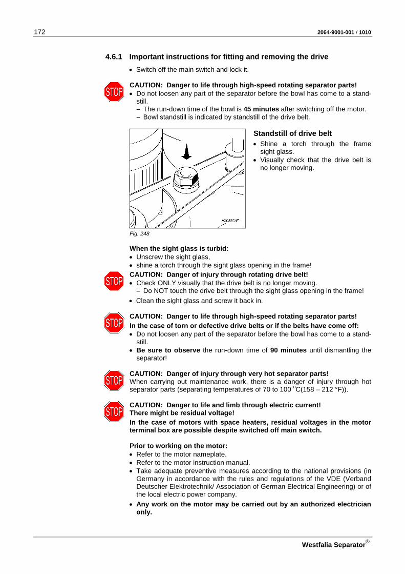
172 2064-9001-001 / 1010
Westfalia Separator®
4.6.1 Important instructions for fitting and removing the drive • Switch off the main switch and lock it.
CAUTION: Danger to life through high-speed rotating separator parts! • Do not loosen any part of the separator before the bowl has come to a stand-
still. – The run-down time of the bowl is 45 minutes after switching off the motor. – Bowl standstill is indicated by standstill of the drive belt.
Standstill of drive belt
• Shine a torch through the frame sight glass.
• Visually check that the drive belt is no longer moving.
Fig. 248
When the sight glass is turbid: • Unscrew the sight glass, • shine a torch through the sight glass opening in the frame!
CAUTION: Danger of injury through rotating drive belt! • Check ONLY visually that the drive belt is no longer moving.
– Do NOT touch the drive belt through the sight glass opening in the frame!
• Clean the sight glass and screw it back in.
CAUTION: Danger to life through high-speed rotating separator parts!
In the case of torn or defective drive belts or if the belts have come off: • Do not loosen any part of the separator before the bowl has come to a stand-
still. • Be sure to observe the run-down time of 90 minutes until dismantling the
separator!
CAUTION: Danger of injury through very hot separator parts! When carrying out maintenance work, there is a danger of injury through hot separator parts (separating temperatures of 70 to 100 oC(158 – 212 °F)).
CAUTION: Danger to life and limb through electric current! There might be residual voltage!
In the case of motors with space heaters, residual voltages in the motor terminal box are possible despite switched off main switch. Prior to working on the motor: • Refer to the motor nameplate. • Refer to the motor instruction manual. • Take adequate preventive measures according to the national provisions (in
Germany in accordance with the rules and regulations of the VDE (Verband Deutscher Elektrotechnik/ Association of German Electrical Engineering) or of the local electric power company.
• Any work on the motor may be carried out by an authorized electrician only.

2064-9001-001 / 1010 173
Westfalia Separator®
• Avoid damage to drive parts when fitting and removing by – precise positioning, – no diagonal pull! – selecting the low lifting speed of the hoist.
CAUTION: Use appropriate lifting devices to prevent accidents! • Use suitably rated, intact hoists.
CAUTION: Danger to life when transporting heavy parts! • Do NOT step under hanging load.
CAUTION: Avoid accidents by using undamaged, complete tools! • Use tools only for their intended use!
– For special tools, see section 4.14 or spare parts catalog. – For standard tools, see section 4.13.
• Do not use force when removing or fitting parts.
• Treat all drive parts – gently. – Always set them down on a rubber mat or a wooden pallet.
ATTENTION: Before fitting the drive parts
• Thoroughly clean and dry the drive chamber. Use only a cleaning agent that is approved for the field of application!
• Check the ball bearings of the spindle and centrifugal clutch. Use only the ball bearings specified in the parts list!
ATTENTION: To avoid bearing damage, • always operate the separator with installed bowl!

174 2064-9001-001 / 1010
Westfalia Separator®
4.6.2 Removing the drive belt and spindle assembly
• Pay special attention to section 4.6.1.
• Undo the oil drain screw and • Drain the oil into an oil pan (approx.
2.5 l).
Fig. 249
• Undo three hex head screws 1. • Take off cover 2.
Fig. 250
• Unscrew four hex head screws 1.
Fig. 251

2064-9001-001 / 1010 175
Westfalia Separator®
• Pull the motor out of the flange guide by means of the hoist (approx. 5 mm). – Drive belt is slackened!
ATTENTION! • Pull the drive belt off the clutch pul-
ley (centrifugal clutch) downwards.
Fig. 252
• Lift the motor with centrifugal clutch out of the lower section of frame.
Fig. 253
Remove the operating water feeding device in the upper section of frame: • Undo nut 2. • Take off pipe 3.
Fig. 254
• Remove spindle cap 1 with fitted gasket.
Fig. 255
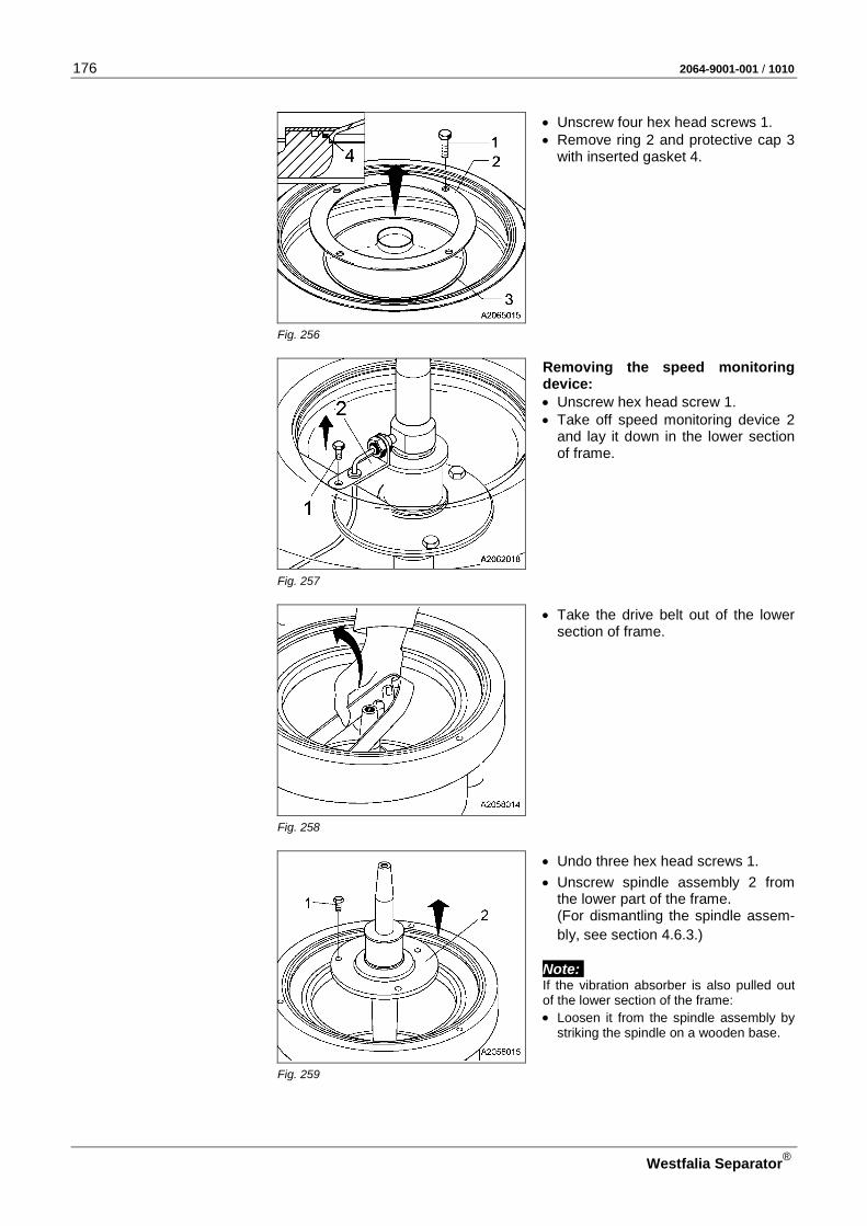
176 2064-9001-001 / 1010
Westfalia Separator®
• Unscrew four hex head screws 1. • Remove ring 2 and protective cap 3
with inserted gasket 4.
Fig. 256
Removing the speed monitoring device: • Unscrew hex head screw 1. • Take off speed monitoring device 2
and lay it down in the lower section of frame.
Fig. 257
• Take the drive belt out of the lower section of frame.
Fig. 258
• Undo three hex head screws 1.
• Unscrew spindle assembly 2 from the lower part of the frame. (For dismantling the spindle assem-bly, see section 4.6.3.)
Note: If the vibration absorber is also pulled out of the lower section of the frame: • Loosen it from the spindle assembly by
striking the spindle on a wooden base.
Fig. 259

2064-9001-001 / 1010 177
Westfalia Separator®
• Remove from the lower part of frame: – Gasket 1 – Rubber-metal cushion 2
Fig. 260
If necessary:
• Undo three hex head screws 1. • remove bearing cover 2 with sealed
hex head screws, disk and cup springs 3 from the lower part of the frame.
Fig. 261
If necessary:
• Take out gasket 1.
Fig. 262
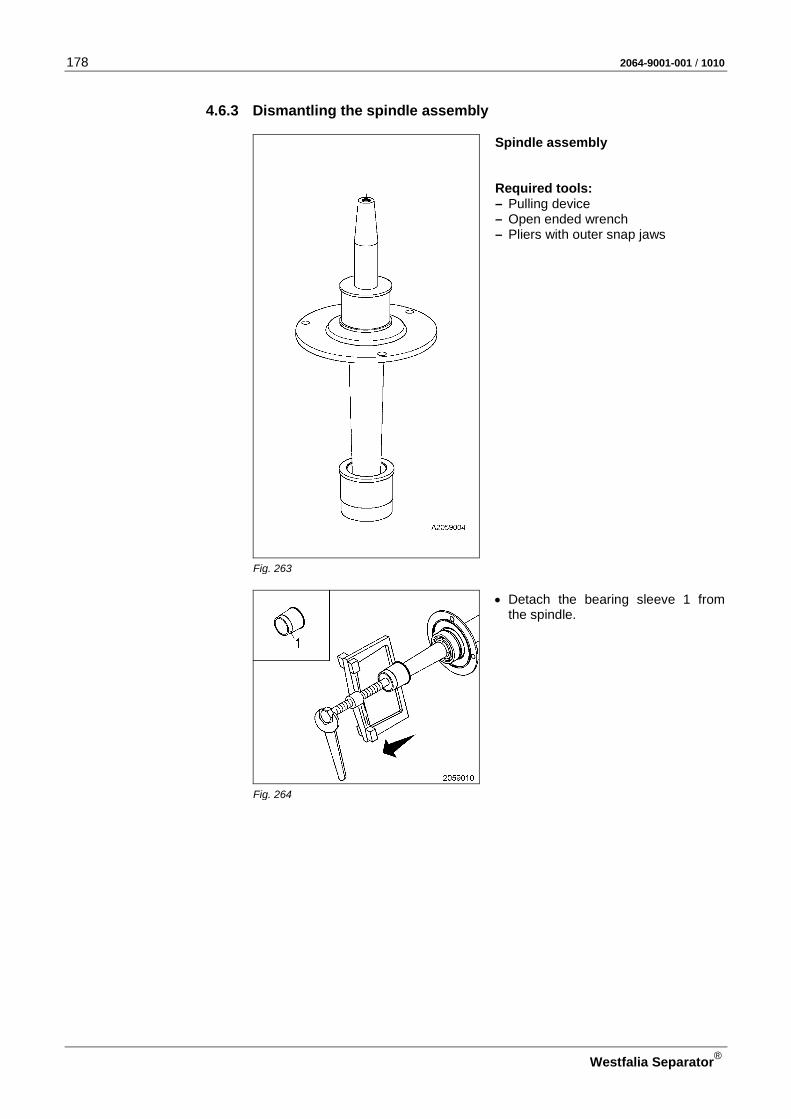
178 2064-9001-001 / 1010
Westfalia Separator®
4.6.3 Dismantling the spindle assembly
Spindle assembly Required tools: – Pulling device – Open ended wrench – Pliers with outer snap jaws
Fig. 263
• Detach the bearing sleeve 1 from the spindle.
Fig. 264

2064-9001-001 / 1010 179
Westfalia Separator®
• Pull off from the spindle: – Angular contact ball bearing 2: – Ball bearing protection ring 3
Fig. 265
• Remove the retaining ring.
Fig. 266
• Pull off from the spindle: – Grooved ball bearing 1 – bearing cover 2 – bearing cover 3
Fig. 267

180 2064-9001-001 / 1010
Westfalia Separator®
4.6.4 Dismantling the centrifugal clutch
• Pay special attention to section 4.6.1.
• Undo three hex head screws 1. • Take off cover 2.
Fig. 268
• Unscrew four hex head screws 1.
Fig. 269
• Pull the motor out of the flange guide by means of the hoist (approx. 5 mm). – Drive belt is slackened!
ATTENTION! • Pull the drive belt off the clutch pul-
ley (centrifugal clutch) downwards.
Fig. 270

2064-9001-001 / 1010 181
Westfalia Separator®
• CAUTION: Danger to life when transporting heavy parts! – Do NOT step under hanging load.
• Lift the motor with fluid clutch out of the lower section of the frame.
Fig. 271
• Turn the motor together with the centrifugal clutch 90o (upside down) with the aid of the hoist.
• CAUTION: Secure from rolling away and overturning using suit-able aids!
Fig. 272
• Undo retaining ring 1.
• Take off disk 2.
Fig. 273
• Pull the clutch shoes out of the clutch driver.
Fig. 274

182 2064-9001-001 / 1010
Westfalia Separator®
• Arrest the clutch driver 1 with an open-ended wrench.
• Unscrew hex head screw 2 from the motor shaft end.
• Take off disk 3.
Fig. 275
Required special tool: – Threaded pin 2 = M 12 x 40 • Arrest the clutch driver 1 with an
open-ended wrench.
ATTENTION! For protecting the mo-tor shaft end: • Screw threaded pin 2 into the thread
of the motor shaft end.
Fig. 276
Required special tools: – Eye bolt 1 – Socket wrench 3 • Unscrew hexagon nut 2
• Screw eye bolt 1 into the clutch driver.
• Arrest the clutch driver with an open-ended wrench.
• Force the centrifugal clutch off the motor shaft end by turning the eye bolt clockwise.
Fig. 277
• Remove eye bolt 1 from the clutch driver and threaded pin 2 from the motor shaft end.
Fig. 278

2064-9001-001 / 1010 183
Westfalia Separator®
• CAUTION: Danger to life when transporting heavy parts! – Do NOT step under hanging load.
• Place the clutch pulley and clutch driver on a wooden base using transport ropes and hoist.
• CAUTION: Secure from rolling away and overturning using suit-able aids!
• Take the retaining ring out of the clutch driver groove.
Fig. 279
• Position wooden block.
• Drive the clutch driver downwards by means of light hammer blows.
• Loosen the clutch driver from the seat of the two ball bearings.
Fig. 280
• Turn the clutch pulley through 90o
(opposite the fitting position) with the aid of the hoist.
• CAUTION: Secure from rolling
away and overturning using suit-able aids!
• Take the retaining rings out of the
clutch drum grooves.
Fig. 281
Required tools – Disk (Ø 86 – 94 mm) – Wooden block – Hammer • Turn the clutch pulley through 180o
and • place it on wooden supports as
shown.
• Drive the grooved ball bearing and spacer bush out of the clutch pulley.
Fig. 282

184 2064-9001-001 / 1010
Westfalia Separator®
4.6.5 Fitting the spindle assembly
• Pay special attention to section 4.6.1.
• For dimensions of the parts see 4.6 - exploded view.
If necessary: • Insert gasket 1 in the groove in the
lower section of frame.
Fig. 283
If necessary:
ATTENTION: Pay attention to the correct fitting position of the cup springs! • Fit bearing cover 1 (with sealed hex
head screws and washer) with cup springs 2 and bolt tight with hex head screws 3.
Fig. 284
ATTENTION: Pay attention to the correct fitting position of the rub-ber-metal cushion! – The two opposite inner holes 2 of
the rubber-metal cushion must be directed upwards.
• Fit rubber-metal cushion 1.
• Insert gasket 3 in the groove in the lower section of frame.
Fig. 285

2064-9001-001 / 1010 185
Westfalia Separator®
• Turn spindle through 180o (upside down).
ATTENTION: Pay attention to the correct fitting position of the bear-ing cover! • Mount bearing covers 1 and 2.
• Heat grooved ball bearing 3 in oil up to 100 oC (212 oF) and slip it onto the spindle.
• Insert retaining ring 4 in the spindle groove.
Fig. 286
• Heat ball bearing protection ring 1 and angular contact ball bearings 2 in oil up to 100 oC (212 oF).
ATTENTION: Bearing damage is caused by incorrect fitting! – When fitting angular contact ball
bearings 2 on the spindle, make sure that the narrow rim of the ball bearing inner ring faces upwards.
• Slide ball bearing protection ring 1 and angular contact ball bearings 2 onto the spindle. Fig. 287
• Heat bearing sleeve 1 in oil up to 100 oC (212 oF).
• Important! Before fitting bearing sleeve 1, make sure that the in-stalled angular contact ball bearing has cooled down to room tempera-ture.
• Slide bearing bush 1 over the angu-lar contact ball bearings and the ball bearing protection ring.
Fig. 288
• Install the assembled spindle as-sembly 1 in the lower part of the frame. – Pay attention to correct position-
ing! ATTENTION: Pay attention to the correct fitting position of the spin-dle! – The holes in the bearing cover must
be aligned with the holes in the lower section of the frame.
• Bolt tight spindle with the three hex head screws 2.
Fig. 289

186 2064-9001-001 / 1010
Westfalia Separator®
4.6.6 Fitting the centrifugal clutch
• Pay special attention to section 4.6.1.
• For dimensions of the parts see 4.6 - exploded view.
• Clean the clutch pulley.
• Insert retaining ring 1 in the lower groove.
• Check that retaining ring 1 is cor-rectly fitted.
Fig. 290
Required tools: – Disk 2 (Ø 86 – 94 mm) – Wooden block – Hammer ATTENTION: Bearing damage is caused by incorrect fitting! – Disk 2 may only contact the outer
ring of grooved ball bearing 1! • Carefully drive the first grooved ball
bearing 1 with disk 2 up to the re-taining ring.
Fig. 291

2064-9001-001 / 1010 187
Westfalia Separator®
ATTENTION: Bearing damage is caused by incorrect fitting! – Distance bush 1 may only contact
the inner ring of grooved ball bear-ing 2!
• Place distance bush on the ball
bearing inner ring.
Fig. 292
ATTENTION: Bearing damage is caused by incorrect fitting! – Disk 2 may only contact the outer
ring of grooved ball bearing 1! • Carefully drive the second grooved
ball bearing 1 with a suitable disk 2 up to the distance sleeve.
Fig. 293
CAUTION: Danger of imbalance by incorrect fitting! • Insert retaining ring 2 180o offset
relative to retaining ring 1 in the up-per groove.
Fig. 294

188 2064-9001-001 / 1010
Westfalia Separator®
Required tool: – Disk 1 (Ø 61 – 69 mm) • CAUTION: Danger to life when
transporting heavy parts! – Do NOT step under hanging load.
• Turn clutch pulley with fitted grooved ball bearings through 180o.
Fig. 295
ATTENTION: Bearing damage is caused by incorrect fitting! – Disk 1 may only contact the inner ring of the grooved ball bearing!
• Place the ball bearing inner ring on disk 1.
ATTENTION: Pay attention to the correct fitting position of the dis-tance bush! – Distance bush 1 must be flush with
the inner rings of the grooved ball bearings.
Fig. 296
Required tools: – Wooden block – Rubber hammer • Carefully hammer the clutch driver
into the grooved ball bearing with light blows.
Fig. 297
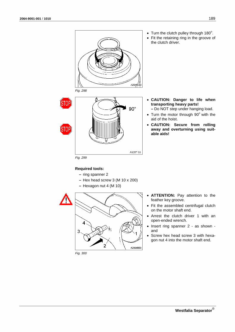
2064-9001-001 / 1010 189
Westfalia Separator®
• Turn the clutch pulley through 180o. • Fit the retaining ring in the groove of
the clutch driver.
Fig. 298
• CAUTION: Danger to life when transporting heavy parts! – Do NOT step under hanging load.
• Turn the motor through 90o with the aid of the hoist.
• CAUTION: Secure from rolling away and overturning using suit-able aids!
Fig. 299
Required tools: – ring spanner 2 – Hex head screw 3 (M 10 x 200) – Hexagon nut 4 (M 10)
• ATTENTION: Pay attention to the feather key groove.
• Fit the assembled centrifugal clutch on the motor shaft end.
• Arrest the clutch driver 1 with an open-ended wrench.
• Insert ring spanner 2 - as shown - and
• Screw hex head screw 3 with hexa-gon nut 4 into the motor shaft end.
Fig. 300
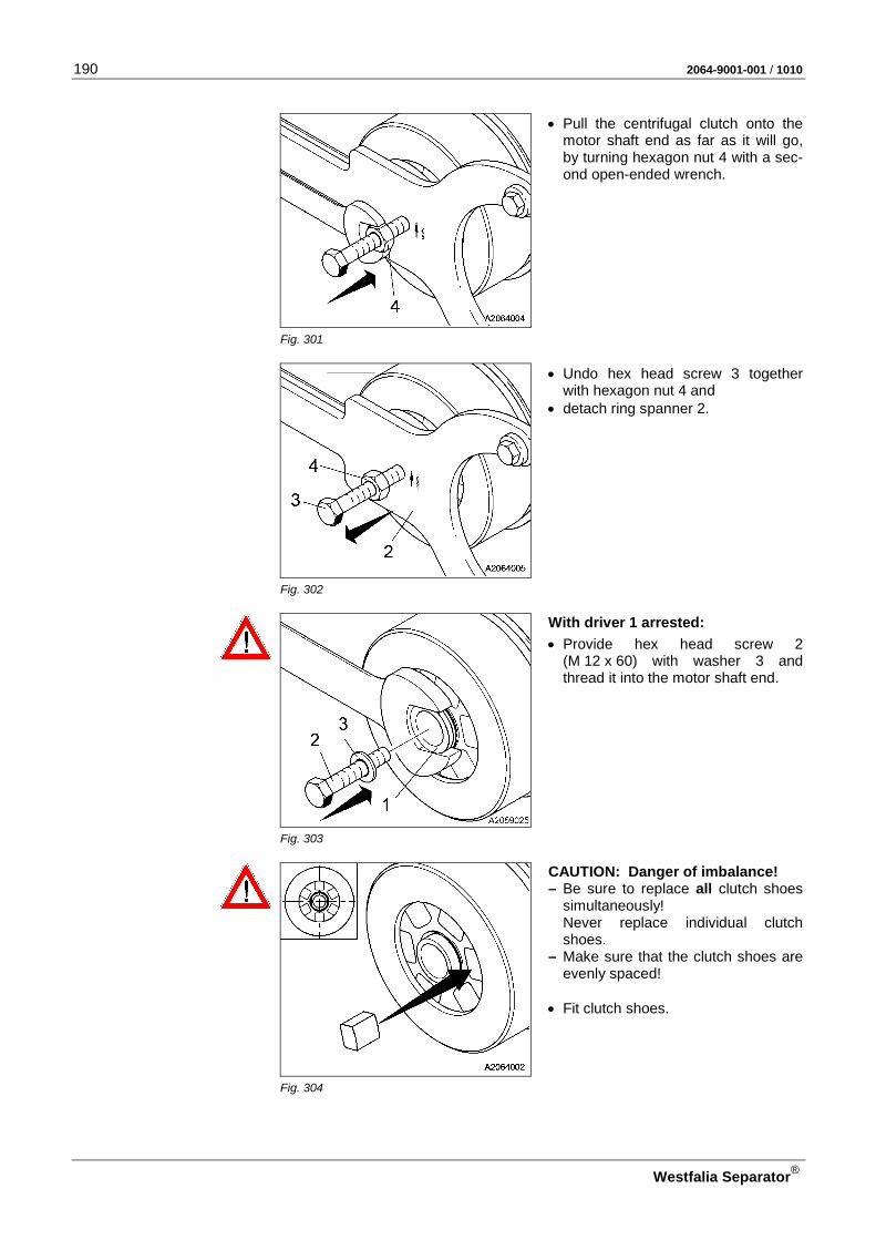
190 2064-9001-001 / 1010
Westfalia Separator®
• Pull the centrifugal clutch onto the motor shaft end as far as it will go, by turning hexagon nut 4 with a sec-ond open-ended wrench.
Fig. 301
• Undo hex head screw 3 together with hexagon nut 4 and
• detach ring spanner 2.
Fig. 302
With driver 1 arrested:
• Provide hex head screw 2 (M 12 x 60) with washer 3 and thread it into the motor shaft end.
Fig. 303
CAUTION: Danger of imbalance! – Be sure to replace all clutch shoes
simultaneously! Never replace individual clutch shoes.
– Make sure that the clutch shoes are evenly spaced!
• Fit clutch shoes.
Fig. 304

2064-9001-001 / 1010 191
Westfalia Separator®
• Insert disk 2.
• Fit the retaining ring 1 in the groove of the clutch driver.
Fig. 305
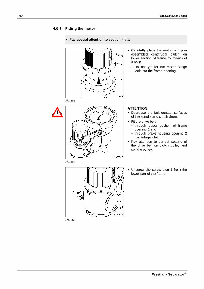
192 2064-9001-001 / 1010
Westfalia Separator®
4.6.7 Fitting the motor
• Pay special attention to section 4.6.1.
• Carefully place the motor with pre-assembled centrifugal clutch on lower section of frame by means of a hoist.
– Do not yet let the motor flange lock into the frame opening.
Fig. 306
ATTENTION: • Degrease the belt contact surfaces
of the spindle and clutch drum.
• Fit the drive belt: – through upper section of frame
opening 1 and – through brake housing opening 2
(centrifugal clutch). • Pay attention to correct seating of
the drive belt on clutch pulley and spindle pulley.
Fig. 307
• Unscrew the screw plug 1 from the lower part of the frame.
Fig. 308

2064-9001-001 / 1010 193
Westfalia Separator®
• Screw hex head screw 1 (M 10 x 200) with hexagon nut 2 and washer 3 through the frame bore into the ta-phole of the centrifugal clutch.
• ATTENTION: To avoid damage to the grooved ball bearing: – do not screw in hex head screw 1
all the way.
• Tension the drive belt by turning hex head nut 2 clockwise until the mo-tor flange locks into the frame open-ing.
Fig. 309
• Fasten the motor with four hex head screws 2 (M 12 x 30).
• Unscrew hex head screw 1 (with
hexagon nut and washer) from the centrifugal clutch.
Fig. 310
• Screw in the screw plug 1.
• Remove the hoist.
Fig. 311
Note: Due to the design concept used, the spindle is at an inclined angle relative to the opposite side of the motor when the drive belt has not been fitted or ten-sioned (see Fig. 312, pos. 2). The spindle is pulled into the centric axis when the belt is tensioned (see Fig. 312, pos. 1).

194 2064-9001-001 / 1010
Westfalia Separator®
• Check – that the spindle 1 can be turned
easily.
– whether the spindle 3 has been pulled into the centric axis by tensioning the drive belt 3 (see Fig. 204).
Fig. 312
Installing the speed monitoring de-vice: • Place speed monitoring device 2 on
the lower section of frame and • fasten with hex head screw 1.
Fig. 313
• Align proximity switch 1 as illu-strated. ATTENTION! The distance X between the spindle and the proximity switch must be 2.5 mm.
Fig. 314
• Insert protective cap 3 with fitted gasket 4 and ring 2 and
• bolt tight with four hex head screws 1 (M 8 x 12).
Fig. 315

2064-9001-001 / 1010 195
Westfalia Separator®
• Place spindle cap 1 with fitted gasket on the spindle. – Pay attention to correct position-
ing!
Fig. 316
Fitting the operating water feeding device in the upper section of frame: • Slide nut 2 over pipe 3. • Fit pipe with nit into the screwed
connection 1 and slide on as far as it will go.
ATTENTION: The narrow end of the pipe must be directed upwards! • Tighten nut 2 firmly.
Fig. 317
• Fit cover 2 to the lower section of the frame with three hex head screws 1 (M 8 x 20).
Fig. 318
• Screw in oil drain screw 1 with fitted gasket.
• Screw in the sight glass 2.
• Fill in oil as described in section 4.3.3 and
• Screw in plug 3 with gasket.
Fig. 319

196 2064-9001-001 / 1010
Westfalia Separator®
Danger to life and limb through electric current! • Have the motor connected by an authorized electrician!
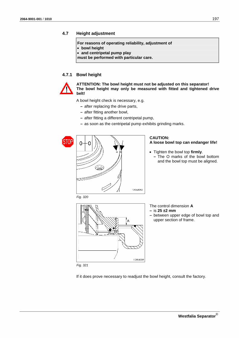
2064-9001-001 / 1010 197
Westfalia Separator®
4.7 Height adjustment
For reasons of operating reliability, adjustment of • bowl height • and centripetal pump play must be performed with particular care.
4.7.1 Bowl height
ATTENTION: The bowl height must not be adjusted on this separator! The bowl height may only be measured with fitted and tightened drive belt!
A bowl height check is necessary, e.g. – after replacing the drive parts, – after fitting another bowl, – after fitting a different centripetal pump, – as soon as the centripetal pump exhibits grinding marks.
CAUTION: A loose bowl top can endanger life! • Tighten the bowl top firmly.
– The O marks of the bowl bottom and the bowl top must be aligned.
Fig. 320
The control dimension A – is 25 ±2 mm – between upper edge of bowl top and
upper section of frame.
Fig. 321
If it does prove necessary to readjust the bowl height, consult the factory.

198 2064-9001-001 / 1010
Westfalia Separator®
4.7.2 Centripetal pump clearance
• Move the centripetal pump axially to and fro in the centripetal pump chamber.
• Measure the total clearance A (approx. 10 Mm).
• Close the hood.
• Check: – Is the hood correctly seated on
the frame rim? – Are the hood screws tightened
firmly?
Fig. 322
• Lightly apply a thin coat of lubricant to the threads of the centripetal pump as specified in the lubrication schedule.
• Fit handle connection piece 1 into the centripetal pump.
• Hold the centripetal pump with offset screwdriver 2.
• Screw handle connection piece into the centripetal pump as far as it will go (left-hand thread).
Fig. 323
• Hold the handle connection piece 1. • Turn the offset screwdriver 2 until
the handle connection piece is raised slightly from the hood (approx. 0.5 mm).
Fig. 324

2064-9001-001 / 1010 199
Westfalia Separator®
• Raise the handle connection piece to its maximum.
• Measure the axial clearance.
A/2 = 4 – 6 mm
Fig. 325

200 2064-9001-001 / 1010
Westfalia Separator®
4.8 Final checks after assembling the separator
Before starting the separator
Perform the following checks after assembling and before starting the separator depending on the scope of the repair work:
Checks Section
1. Bowl height 4.7.1 2. Oil level in drive chamber 4.3.3 3. Direction of rotation of the bowl 4.1.4 4. Bowl speed 4.1.5 5. Starting time of bowl / current consumption 4.1.5 6. Running characteristics of the separator 3.8.1 7. Suction line of the product pump (if installed) for leakage
When starting the separator
Perform the following checks after carrying out repairs:
Checks Section
1. Temperature of product
2. Observe discharges for water, solids and oil to see if the bowl is operating correctly.
3.3
4.9 Before a long-term shut-down of the separator • Disconnect all electrical connections.
• Thoroughly clean the separator (see section 4.4.2, 4.4.3 and 4.4.4).
• Dry and grease the clean bowl parts and all unvarnished machine parts to avoid corrosion damage.
• Store the clean, greased bowl in a dry place until reuse.
• Store the gaskets in a cool, dry, dust-free dark room to prevent them from be-coming brittle.
• Check if the shut-off valves for water leak.
• If necessary, disconnect the water lines to prevent damage by dripping water.
4.9.1 Preserving the separator • Drain the lube oil completely.
Observe the local regulations on disposal of the lubricating oil.
• Fill the drive chamber with a slushing oil, e.g. Shell oil S.7294 (SAE 30/SAE 50), to the middle of the sight glass.
• Let the separator run without bowl for approx. 1 minute to make sure that all drive parts are coated with slushing oil.
2064-9001-001 / 1010 201
Westfalia Separator®
CAUTION! Risk of injury through rotating separator parts. • Keep a safe distance away from the rotating spindle. • After switching off the separator, wait until the spindle has stopped rotating.
• Take off the drive belt.
4.9.2 Preserving the motor • Follow the instructions of the motor manufacturer.

202 2064-9001-001 / 1010
Westfalia Separator®
4.10 Storage
ATTENTION! Improper and incorrect storage of the separator and control unit can dam-age or destroy their components. Store accessories like spare parts, tools, lubricants properly!
Note: Gaskets, hoses and hosepipes, for example, change their physical properties in unfavourable storage conditions. This can result in a shorter service life. They can be rendered useless due to excessive hardening, softening, permanent de-formation, flaking, cracks or other surface damage.
IMPORTANT: • Outdoor exposure is not admissible!
4.10.1 After delivery If the separator and control unit are not installed immediately after delivery, • store the separator and control unit in the original transport packaging.
Recommended storage temperature: + 5 to +50 °C (41 – 122 °F)
IMPORTANT: A storage time of more than 12 months of the separator and control unit is only possible after consulting the manufacturer.
4.10.2 Separator The following procedure applies
– for storing the separator before commissioning and – for storing the separator before a prolonged standstill period.
IMPORTANT: • Store the separator with dismantled bowl!
• Store the clean, greased bowl in a dry place.
• Store the gaskets in a cool, dry, frost-free, dust-free dark room to prevent them from becoming brittle. Recommended storage temperature: + 5 to +50 °C (41 - 122 °F)
• The separator with dismantled bowl must be stored dry and free from vibra-tions. (Vibrations during standstill can cause bearing damage!).
• Protect the drive spindle and motor from dust.
• Store all other separator parts dry and frost-free.
4.10.3 Control system
• The control unit and accessories must be stored dry, dust-free, vibration and frost-free.
• Protect from excessive heat!

2064-9001-001 / 1010 203
Westfalia Separator®
Recommended storage temperature: + 5 to + 45 °C (41 – 113 °F)
4.11 Before restarting
Before re-starting, the operator must ensure
• that all separators and plant components have been function-checked by competent personnel (qualified specialists).
• that the maintenance intervals are adhered to.
• that the separator is assembled correctly by competent persons.
Note:
If the bowl has been out of operation for longer than 6 months (e.g. due to a long standstill period or storage), • check all bowl parts as specified in the maintenance schedule (table “Mainte-
nance after 4000 operating hours or after 6 months at the latest”). • Replace if necessary.
If the separator has been out of operation for longer than 12 months (e.g. due to a long standstill period or storage), • check all separator parts in accordance with the maintenance schedule (table
“Maintenance after 8000 operating hours or after 1 year at the latest). • Replace if necessary.
Procedure: • Drain the slushing oil.
Observe the local regulations on disposal of the slushing oil.
• Remove the grease from all unpainted machine parts.
• Check gaskets. Replace damaged, very swollen, hardened or brittle gaskets immediately.
• Assemble the bowl (see section 4.4.7).
• Check the ball bearings of the spindle and centrifugal clutch (if applicable). When damaged, replace the ball bearings immediately !
• Fit drive belt (see section 4.6.5 or 4.6.7). When damaged, replace the drive belt immediately !
• Assemble the separator correctly.
• Fill the drive chamber with the specified lube oil as specified in section 4.3.3.
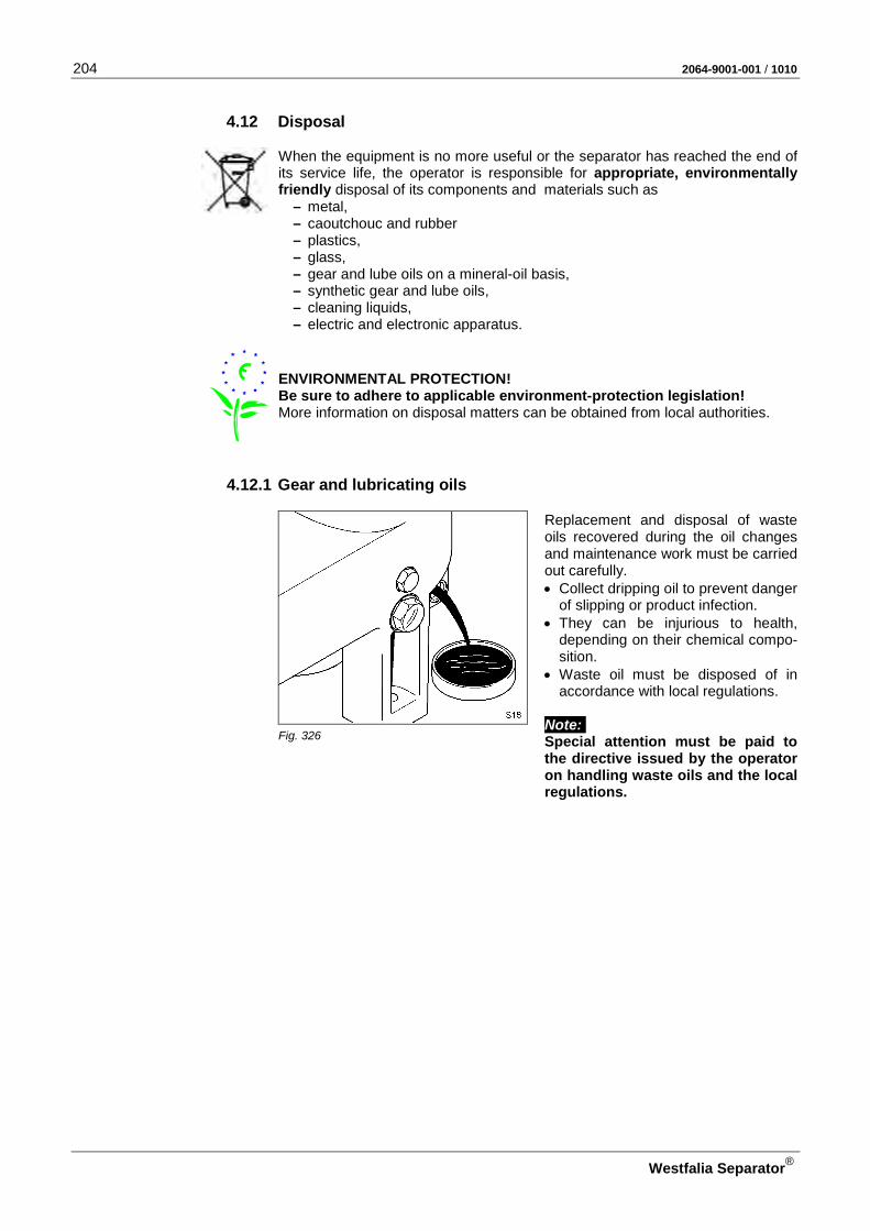
204 2064-9001-001 / 1010
Westfalia Separator®
4.12 Disposal
When the equipment is no more useful or the separator has reached the end of its service life, the operator is responsible for appropriate, environmentally friendly disposal of its components and materials such as
– metal, – caoutchouc and rubber – plastics, – glass, – gear and lube oils on a mineral-oil basis, – synthetic gear and lube oils, – cleaning liquids, – electric and electronic apparatus.
ENVIRONMENTAL PROTECTION! Be sure to adhere to applicable environment-protection legislation! More information on disposal matters can be obtained from local authorities.
4.12.1 Gear and lubricating oils
Replacement and disposal of waste oils recovered during the oil changes and maintenance work must be carried out carefully. • Collect dripping oil to prevent danger
of slipping or product infection. • They can be injurious to health,
depending on their chemical compo-sition.
• Waste oil must be disposed of in accordance with local regulations.
Note: Special attention must be paid to the directive issued by the operator on handling waste oils and the local regulations.
Fig. 326
2064-9001-001 / 1010 205
Westfalia Separator®
4.12.2 Cleaning liquids Only those cleaning agents may be used that are specified in the overall docu-mentation (see data sheet).
CAUTION: Danger of chemical burns! The cleaning agents can be acids and caustics which, if used carelessly, can cause severe damage to persons.
Note: Pay particular attention to the directive issued by the operator on handling the cleaning agents used and the local disposal regulations.
4.12.3 Separator Before disposing of the separator
• Drain the gear oil and dispose of it properly in accordance with section 4.12.1.
• Dismantle the separator, remove any lubricant sticking to separator parts and dispose of them separately or recycle them where appropriate.

206 2064-9001-001 / 1010
Westfalia Separator®
4.13 Standard tools are commercially available tools to be supplied by the customer.
Fig. 327

2064-9001-001 / 1010 207
Westfalia Separator®
Pos. Designation
1 Screwdriver 2 Torque wrench (0 - 100 Nm)
with inserts and extension 3 Caliper gauge 4 Electric oil heater for ball bearings 5
Ratchet with inserts and extension
6 Standard hammer and mallet 7 Inner snap pliers with offset jaws
(Ø 40 mm) 8 Outer snap pliers (Ø 35 mm) 9 Hand tachometer
10 Wrench, adjustable
11 Brushes 12 Puller (200 x 200 mm (H x W))
13 Open-ended wrench (jaw spans: 19, 32, 55 mm)
14 Wooden blocks 15 Drill
16 Drill bit (Ø 2 mm)
17 Wooden screws (max. Ø 4 mm x 50 mm length)
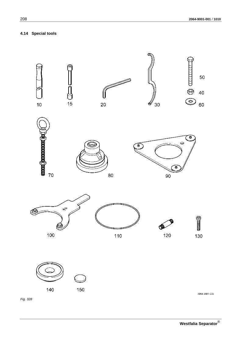
208 2064-9001-001 / 1010
Westfalia Separator®
4.14 Special tools
Fig. 328
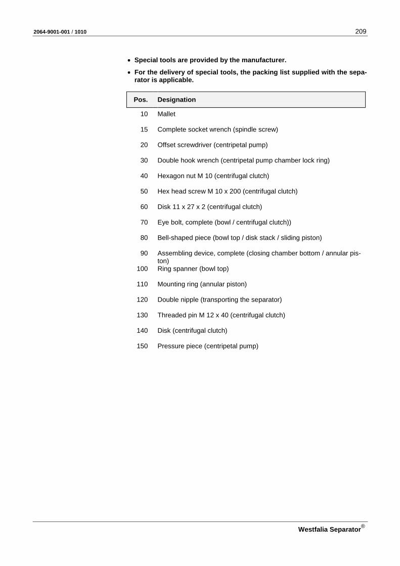
2064-9001-001 / 1010 209
Westfalia Separator®
• Special tools are provided by the manufacturer.
• For the delivery of special tools, the packing list supplied with the sepa-rator is applicable.
Pos. Designation
10 Mallet
15 Complete socket wrench (spindle screw)
20 Offset screwdriver (centripetal pump)
30 Double hook wrench (centripetal pump chamber lock ring)
40 Hexagon nut M 10 (centrifugal clutch)
50 Hex head screw M 10 x 200 (centrifugal clutch)
60 Disk 11 x 27 x 2 (centrifugal clutch)
70 Eye bolt, complete (bowl / centrifugal clutch))
80 Bell-shaped piece (bowl top / disk stack / sliding piston)
90 Assembling device, complete (closing chamber bottom / annular pis-ton)
100 Ring spanner (bowl top)
110 Mounting ring (annular piston)
120 Double nipple (transporting the separator)
130 Threaded pin M 12 x 40 (centrifugal clutch)
140 Disk (centrifugal clutch)
150 Pressure piece (centripetal pump)

210 2064-9001-001 / 1010
Westfalia Separator®
NNoottee NNootteess
NNoottiizzeenn AAnnoottaacciioonneess ДДлляя ззааппииссеейй MMuuiissttiiiinnppaannoott ΣΣηημμεειιώώσσεειιςς
NNoottaatteerr NNootteess NNoottee

2064-9001-001 / 1010 211
Westfalia Separator®
5 Spare parts
5.1 Spare part requirements ...................................................................... 212 5.2 Guide to ordering spare parts .............................................................. 212

212 2064-9001-001 / 1010
Westfalia Separator®
5.1 Spare part requirements
• Use only genuine spare parts from GEA Westfalia Separator. The original spare parts are listed in the spare parts catalog. The use of non-genuine parts leads to: – safety risks, – reduced durability of these parts, – reduced availability of the separator and – increased service requirement.
If a safety risk occurs when using non-original spare parts, this may have legal consequences for the responsible persons. In such cases, GEA Westfalia Separator accepts no liability or war-ranty claims.
Fig. 329
5.2 Guide to ordering spare parts A rapid and correct supply of spare parts can only be guaranteed if your order includes the following details:
• Separator model see name-plate
e.g. OSE 20-0136-067 • Serial-No. see name-plate
e.g. 9000-223 • Designation see order-specific parts catalog
e.g. frame • Part Number see order-specific parts catalog
e.g. 2050-1100-020 The part number is also marked on almost all the individual parts.
Only when ordering spare parts for bowls: • Bowl S/N If this differs from the serial number.
The bowl serial number is engraved on the bowl lock ring, bowl bottom and bowl top.
Only required when ordering spare parts for pump and pump connection parts:
• Model and number of pump
see pump nameplate
The information provided must be complete to avoid incorrect deliveries.
Available sets of spare parts The following sets of spare parts are available depending on the respective technical maintenance intervals:
– Set of spare parts “bowl and hood” for operation of 1 year or 8000 hours – Set of spare parts “Drive” for operation of 1 year or 8000 hours – Set of spare parts “Drive” for operation of 2 years or 16,000 hours
The maintenance schedule forms the systematic maintenance basis for the use of these sets of spare parts.
2064-9001-001 / 1010 213
Westfalia Separator®
NNoottee NNootteess
NNoottiizzeenn AAnnoottaacciioonneess ДДлляя ззааппииссеейй MMuuiissttiiiinnppaannoott ΣΣηημμεειιώώσσεειιςς
NNoottaatteerr NNootteess NNoottee
214 2064-9001-001 / 1010
Westfalia Separator®
NNoottee NNootteess
NNoottiizzeenn AAnnoottaacciioonneess ДДлляя ззааппииссеейй MMuuiissttiiiinnppaannoott ΣΣηημμεειιώώσσεειιςς
NNoottaatteerr NNootteess NNoottee
2064-9001-001 / 1010 215
Westfalia Separator®

GEA Mechanical Equipment
GEA Westfalia Separator Group GmbH
Werner-Habig-Str. 1, 59302 Oelde (Germany) Phone +49 2522 77-0, Fax +49 2522 77-2488 [email protected], www.westfalia-separator.com