4. Building HVAC Requirements · Building HVAC Requirements – Overview Page 1 2008 Residential...
116
Building HVAC Requirements – Overview Page 1 2008 Residential Compliance Manual August 2009 4. Building HVAC Requirements 4.1 Overview 4.1.1 Introduction and Organization This chapter addresses the requirements for heating, ventilating, and air conditioning (HVAC) systems. The requirements are presented in this chapter so that it may serve as a single source of information for mechanical system designers and mechanical system installers, as well as energy consultants, HERS raters and enforcement personnel. Each section in this chapter outlines the mandatory measures and when applicable, the prescriptive requirements or compliance options. These prescriptive requirements vary by climate zone. When the building design does not achieve the minimum prescriptive requirements, then the compliance options may be used under the performance approach to achieve compliance. The chapter is organized under the following sections: 1. Heating Equipment. This section addresses the requirements for heating equipment, including mandatory measures, prescriptive requirements, and compliance options. 2. Cooling Equipment. This section addresses cooling equipment requirements, including mandatory measures, prescriptive requirements, and compliance options. 3. Air Distribution System Ducts, Plenums. This section covers mandatory requirements such as duct insulation, duct system construction practices and duct diagnostic testing. This section also covers prescriptive specifications for access holes in the supply and return plenums to accommodate pressure and temperature measurements by installers and HERS raters. 4. Controls. This section addresses mandatory requirements for thermostats and the compliance option for zonal controls. 5. Indoor Air Quality and Mechanical Ventilation. This section covers mandatory requirements for indoor air quality including mechanical ventilation. 6. Alternative Systems. This section covers a number of systems that are less common in California homes, including hydronic heating, radiant floor systems, evaporative cooling, gas cooling, ground-source heat pumps, and wood space heating. 7. Compliance and Enforcement. In this section the documentation requirements at each phase of the project are highlighted. 8. Refrigerant Charge . More information on the refrigerant charge verification procedures is included in this section.
Transcript of 4. Building HVAC Requirements · Building HVAC Requirements – Overview Page 1 2008 Residential...

Building HVAC Requirements – Overview Page 1
2008 Residential Compliance Manual August 2009
4. Building HVAC Requirements
4.1 Overview
4.1.1 Introduction and Organization This chapter addresses the requirements for heating, ventilating, and air conditioning (HVAC) systems. The requirements are presented in this chapter so that it may serve as a single source of information for mechanical system designers and mechanical system installers, as well as energy consultants, HERS raters and enforcement personnel.
Each section in this chapter outlines the mandatory measures and when applicable, the prescriptive requirements or compliance options. These prescriptive requirements vary by climate zone. When the building design does not achieve the minimum prescriptive requirements, then the compliance options may be used under the performance approach to achieve compliance.
The chapter is organized under the following sections:
1. Heating Equipment. This section addresses the requirements for heating equipment, including mandatory measures, prescriptive requirements, and compliance options.
2. Cooling Equipment. This section addresses cooling equipment requirements, including mandatory measures, prescriptive requirements, and compliance options.
3. Air Distribution System Ducts, Plenums. This section covers mandatory requirements such as duct insulation, duct system construction practices and duct diagnostic testing. This section also covers prescriptive specifications for access holes in the supply and return plenums to accommodate pressure and temperature measurements by installers and HERS raters.
4. Controls. This section addresses mandatory requirements for thermostats and the compliance option for zonal controls.
5. Indoor Air Quality and Mechanical Ventilation. This section covers mandatory requirements for indoor air quality including mechanical ventilation.
6. Alternative Systems. This section covers a number of systems that are less common in California homes, including hydronic heating, radiant floor systems, evaporative cooling, gas cooling, ground-source heat pumps, and wood space heating.
7. Compliance and Enforcement. In this section the documentation requirements at each phase of the project are highlighted.
8. Refrigerant Charge . More information on the refrigerant charge verification procedures is included in this section.

Page 2 Building HVAC Requirements – Overview
2008 Residential Compliance Manual August 2009
Chapter 9 covers the heating and cooling requirements for additions to existing dwellings and for alterations to existing heating and cooling systems.
4.1.2 What’s New for the 2013 Standards The following is a summary of the new HVAC measures for the 2013 Standards. It also includes new compliance options that provide greater flexibility in complying with the Standards when using the performance method. See individual sections of this Manual for more detail.
Mandatory Features and Devices - Section 150.0
1. The indoor design temperature for heating load calculations has been changed from 70 degrees to 68 degrees. [150.0(h)2]
2. Air conditioning condensers are required to be located at least 5 feet from a clothes dryer vent outlet. [150.0(h)3]
3. Gas furnaces must be designed and installed to meet the manufacturer’s maximum temperature split in heating mode. [150.0(h)4]
4. There are some changes to the tables specifying mandatory minimum insulation on air conditioning refrigerant lines. [150.0(j)2C]
5. There are some changes to the mandatory insulation protection for insulated pipes found outside conditioned space. [150.0(j)3B]
6. There is a new reference to a mandatory duct construction standard, ANSI/SMACNA-006-2006 HVAC Duct Construction Standard. [150.0(m)1]
7. The mandatory minimum duct insulation R-value has been raised from R-4.2 to R-6, except for ducts located completely within directly conditioned space. [150.0(m)1]
8. Duct sealing and field verification is now a mandatory measure (moved from the prescriptive packages) and can no longer be traded off by using the performance approach. [150.0(m)11]
9. There are some changes to the target leakage rates for dwellings in multi-family buildings. [150.0(m)11]
10. There are new mandatory requirements for filtration of all air passing through a ducted space conditioning system. The requirements affect the design, efficiency, pressure drop and labeling of the filtration devices. [150.0(m)12]
11. There are new mandatory requirements to ensure proper duct and filter grill sizing. They include requirements for a hole for a static pressure probe (HSPP) and an option to either size ducts based on prescriptive tables or field testing to meet airflow and fan watt requirements. [150.0(m)13]
12. There are some new mandatory requirements for systems that utilize automatic zonal control to meet airflow and fan watt draw requirements. [150.0(m)15]

Building HVAC Requirements – Overview Page 3
2008 Residential Compliance Manual August 2009
13. The mandatory whole building ventilation requirement of ASHRAE 62.2 is now a HERS verified measure. [150.0(o)]
Prescriptive and Performance Compliance Approaches - Section150.1
1. When higher than minimum SEER ratings are specified using the performance approach, installation of proper equipment is now a HERS verified measure. Previously this only applied to high EER equipment. [150.1(b)4Bi]
2. There is now only one set of prescriptive measures (prescriptive package A). [150.1(c)]
3. There is a new allowance for supplemental heating systems. It includes limitations on size and requirements for timing controls. [150.1(c)6]
4. The temperature split approach to minimum airflow verification for refrigerant charge verification has been omitted. This reduces the number of required measurement access holes from two to one. [150.1(c)7Aib]
5. Some package units, mini-splits and variable refrigerant flow systems will be required to demonstrate proper refrigerant charge using a weigh-in approach and must be verified by a HERS rater. [150.1(c)7Aii]
6. Ducts not insulated because they are deemed to be in directly conditioned space must be verified by a HERS rater utilizing the duct leakage to outside procedures. [150.1(c)9]
7. There is a new prescriptive requirement in climate zones 8 through 14 for whole house fans designed to provide ventilation cooling. [150.1(c)12]
8. When homes utilizing the prescriptive approach have automatic zonal control, they are prohibited from using bypass ducts that divert supply air directly back to the return air stream. Using the performance approach, there is an energy penalty for systems choosing to utilize bypass ducts for zonal control. [150.1(c)13]
9. Maximum Rated Total Cooling Capacity compliance credit has been deleted
Additions and Alterations - Section 150.2 The new requirements in the 2013 Standards for HVAC systems in homes that are altered or added to are summarized and discussed in Chapter 9.
4.1.3 Common System Types The typical new California home in the central valley and the desert has a gas furnace and a split system air conditioner. Both heating and cooling is typically distributed to each of the rooms through air ducts. Most of the mandatory measures and prescriptive requirements are based on this type of system. In some areas, a heat pump provides both heating and cooling, eliminating the furnace. In coastal climates and in the mountains, air conditioning is rare and most new homes are heated by gas furnaces.

Page 4 Building HVAC Requirements – Overview
2008 Residential Compliance Manual August 2009
Although the Standards focus on the typical system, they also apply to other systems as well, including some radiant hydronic systems where hot water is distributed to parts of the home to provide at least some of the heat to conditioned space.
Electric resistance systems are used in some areas and applications, although it is difficult for them to comply under the Standards.
Ground-source or water source heat pump (geo-exchange) systems are also used, especially in areas where there is no gas service. Unlike the more typical air source systems, these utilize water circulated underground or in large ponds or lakes as the heat source (in heating mode) and heat sink (in cooling mode).
This chapter focuses mostly on typical systems, but a section is provided to deal with the alternative systems as well.
4.1.4 Appliance Standards and Equipment Certification §110.0 – General
§110.1 – Appliance Efficiency Regulations
Most heating and cooling equipment installed in new California homes is regulated by the National Appliance Efficiency Conservation Act (NAECA) and/or the California Appliance Efficiency Regulations (Title 20). Both the federal and state appliance standards apply to the manufacture of new equipment and are applicable for equipment used in replacements, repairs or for any other purpose. The Appliance Efficiency Regulations are enforced at the point of sale, while the Energy Efficiency Standards explained this compliance manual are enforced by local enforcement agencies.
The following types of equipment (in the table below) are covered by the Appliance Efficiency Regulations. For this equipment, the manufacturer must certify that the equipment complies with the current Appliance Efficiency Regulations at the time of manufacture.
Appliances Covered by the Appliance Efficiency Regulations:
• Room air conditioners • Room air conditioning heat pumps • Central air conditioners with a
cooling capacity of less than 135,000 Btu/hr
• Central air conditioning heat pumps
• Gas-fired central furnaces • Gas-fired boilers • Gas-fired furnaces • Gas-fired floor furnaces • Gas-fired room heaters • Gas-fired duct furnaces • Gas-fired unit heaters
The Appliance Efficiency Regulations do not require certification for:
1. Infrared heaters
2. Electric resistance heaters
3. Oil-fired furnaces (some are voluntarily listed with certified gas-fired furnaces).

Building HVAC Requirements – Heating Equipment Page 5
2008 Residential Compliance Manual August 2009
Equipment that does not meet the Federal Appliance Efficiency Standards may not be sold in California. Any equipment covered by the Appliance Efficiency Regulations and sold in California must have the date of manufacture permanently displayed in an accessible place on that equipment. This date is frequently included as part of the serial number.
Note: Equipment manufactured before the effective date of a new standard may be sold and installed in California indefinitely, as long as the performance and prescriptive approach demonstrates energy compliance of the building using the lower efficiency of the relevant appliances.
The compliance and enforcement process should ensure that all installed HVAC equipment regulated by the Appliance Efficiency Regulations is certified to the Energy Commission.
Plan Review Process (Compliance)
During the plan review process builder must show compliance with the Appliance Efficiency Regulations by providing the efficiency of the HVAC equipment that is to be installed. Typically the builder does not identify the exact make or model at this point during the process. The Plans Examiner is responsible for verifying that the specified equipment efficiency complies with the Appliance Efficiency Regulations.
Field Inspection (Enforcement)
It is the responsibility of The Field Inspector to visually verify that the product information on the installed HVAC equipment matches the efficiency that was approved by the Plans Examiner. To facilitate the inspection process the Field Inspector may reference the CF-6R-MECH-04 form submitted by the builder/installing contractor. Additionally, the Field Inspector must also verify that the installed HVAC equipment is certified to the Energy Commission. The Field Inspector, at their discretion, may require the builder/installing contractor to provide a print out from the Energy Commission Appliance Efficiency Database of certified equipment listing the same make and model that is installed.
If the specifications labeled on the HVAC equipment do not match the equipment specifications on the Energy Commission Appliance Efficiency Database, the Inspector shall issue a correction notice to the builder/installing contractor. The following statement may be used as a correction notice.
4.2 Heating Equipment This section addresses the requirements for heating equipment, including furnaces, boilers, heat pumps and electric resistance equipment.
4.2.1 Mandatory Measures for Heating Equipment
A. Equipment Efficiency §110.1 and §110.2(a)
Appliance Efficiency Regulations

Page 6 Building HVAC Requirements – Heating Equipment
2008 Residential Compliance Manual August 2009
The efficiency of most heating equipment is regulated by NAECA (the federal appliance standard) and the California Appliance Efficiency Regulations. These regulations are not contained in the Building Energy Efficiency Standards but are published separately. These regulations are referenced in §110.1. The Appliance Efficiency Regulations include definitions for all types of equipment. The energy efficiency of larger equipment is regulated by §110.2(a). Also, see the Nonresidential Compliance Manual for more information on larger equipment.
1. Gas and Oil-Fired Furnaces
The current Appliance Efficiency Regulations require that the Annual Fuel Utilization Efficiency (AFUE) of all new gas and oil-fired central furnaces with a single phase electrical supply be at least 78% with an output capacity less than 225,000 Btu/hr.
Gas and oil-fired central furnaces with outputs greater than or equal to 225,000 Btu/hr are rated according to their Thermal (or Steady State) Efficiency. The minimum Thermal Efficiency for large gas furnaces is 80% and 81% for large oil-fired central furnaces.
Building HVAC Requirements – Heating Equipment Page 7
2008 Residential Compliance Manual August 2009
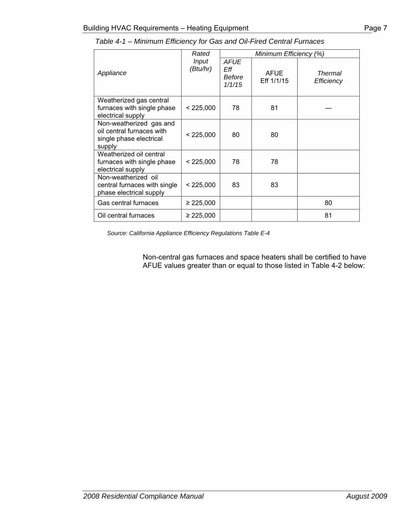
Table 4-1 – Minimum Efficiency for Gas and Oil-Fired Central Furnaces
Appliance
Rated Input
(Btu/hr)
Minimum Efficiency (%) AFUE Eff Before 1/1/15
AFUE Eff 1/1/15
Thermal Efficiency
Weatherized gas central furnaces with single phase electrical supply
< 225,000 78 81 —
Non-weatherized gas and oil central furnaces with single phase electrical supply
< 225,000 80 80
Weatherized oil central furnaces with single phase electrical supply
< 225,000 78 78
Non-weatherized oil central furnaces with single phase electrical supply
< 225,000 83 83
Gas central furnaces ≥ 225,000 80
Oil central furnaces ≥ 225,000 81
Source: California Appliance Efficiency Regulations Table E-4
Non-central gas furnaces and space heaters shall be certified to have AFUE values greater than or equal to those listed in Table 4-2 below:

Page 8 Building HVAC Requirements – Heating Equipment
2008 Residential Compliance Manual August 2009
Table 4-2 – Minimum Heating Efficiency for Non-Ducted, Non-Central Gas Fired Heating Equipment
Type Capacity AFUE
Wall Furnace (fan type)
up to 42,000 Btu/hour 73%
over 42,000 Btu/hour 74%
Wall Furnace (gravity type)
up to 10,000 Btu/hour 59%
over 10,000 Btu/hour up to 12,000 Btu/hour 60%
over 12,000 Btu/hour up to 15,000 Btu/hour 61%
over 15,000 Btu/hour up to 19,000 Btu/hour 62%
over 19,000 Btu/hour up to 27,000 Btu/hour 63%
over 27,000 Btu/hour up to 46,000 Btu/hour 64%
over 46,000 Btu/hour 65%
Floor Furnace up to 37,000 Btu/hour 56%
over 37,000 Btu/hour 57%
Room Heater
up to 18,000 Btu/hour 57%
over 18,000 Btu/hour up to 20,000 Btu/hour 58%
over 20,000 Btu/hour up to 27,000 Btu/hour 63%
over 27,000 Btu/hour up to 46,000 Btu/hour 64%
over 46,000 Btu/hour 65%
Source: California Appliance Efficiency Regulations Table E-2
2. Heat Pumps and Electric Heating
Heat pumps shall be certified to have a HSPF or COP equal to or better than those listed in Table 4-3 below:

Building HVAC Requirements – Heating Equipment Page 9
2008 Residential Compliance Manual August 2009
Table 4-3 – Minimum Heating Efficiency for Heat Pumps
Equipment Type
Appliance Efficiency Reg.
Reference
Configuration/Size Minimum Heating Efficiency
Packaged terminal heat
pumps
Table B-3 Any 1.3 +[0.16(10.0-[0.00016 x Cap1)] =
COP
Single phase air source heat
pumps (NAECA)
Table C-2 < 65,000 Btu/h Cooling Capacity prior to 1/1/2015
Packaged 7.7 HSPF Split 7.7 HSPF
< 65,000 Btu/h Cooling Capacity effective 1/1/2015
Packaged 8.0 HSPF Split 8.2 HSPF
Space Constrained < 65,000 Btu/h Cooling Capacity
Packaged 7.4 HSPF Split 7.4 HSPF
Small duct high velocity < 65,000 Btu/h Cooling Capacity
7.7 HSPF
Three-phase air source heat
pumps
Table C-3 < 65,000 Btu/h Packaged 7.4 HSPF Split 7.4 HSPF
≥ 65,000 and <135,000 3.3 COP
≥ 135,000 and <240,000 3.2 COP
≥ 240,000 and <760,000 3.2 COP
Water-source heat pumps
Table C-5 < 135,000 Btu/h 4.2 COP
≥ 135,000 Btu/h, < 240,000 Btu/h 2.9 COP
Single package
vertical heat pumps
Table C-6 < 65,000 Single Phase 3.0 COP
< 65,000 3-Phase 3.0 COP
≥ 65,000 and < 135,000 3.0 COP
≥ 135,000 and < 240,000 2.9 COP
1. Cap = Cooling Capacity
Source: California Appliance Efficiency Regulations
There are no minimum appliance efficiency standards for electric-resistance or electric-radiant heating systems.
3. Gas and Oil-Fired Central Boilers and Electric Boilers
Gas and oil-fired central boilers shall be certified to have and AFUE or Combustion Efficiency equal to or better than those listed in Table 4-4 below:

Page 10 Building HVAC Requirements – Heating Equipment
2008 Residential Compliance Manual August 2009
Table 4-4 – Minimum Efficiency for Gas and Oil Fired Central Boilers Source: California Appliance Efficiency Regulations Table E-3
Appliance Rated Input (Btu/hr)
Minimum Efficiency (%)
AFUE Combustion Efficiency at
Maximum Rated Capacity
Effective September 1, 2012
Gas steam boilers with single phase electrical supply
< 300,000 80 ¹ —
Gas hot water boilers with single phase electrical supply
< 300,000 82 ¹,² —
Oil steam boilers with single phase electrical supply
< 300,000 82 —
Oil hot water boilers with single phase electrical supply
< 300,000 84 ² —
All other boilers with single phase electrical supply
< 300,000 — —
Gas packaged boilers ≥ 300,000 — 80
Oil packaged boilers ≥ 300,000 — 83 ¹ No constant burning pilot light design standard. ² Automatic means for adjusting temperature design standard.
B. Heating System Controls §150.0(i), 110.2(b), Exceptions to §110.2(b), 110.2(c), Exception to 110.2(c)
All unitary heating systems, including heat pumps, must be controlled by a setback thermostat. These thermostats must be capable of allowing the occupant to program the temperature set points for at least four different periods in 24 hours. For example, the setback thermostat could be programmed at specific temperature starting at 6:30 am, 9:00 am, 4:30 pm and 9:00 pm, thus allowing for four periods within 24 hours.
If the heating system is integrated into a central energy management control system (EMCS), then that system does not need to comply with the set back requirements. Additionally, all gravity gas wall heaters, floor heaters, room heaters and fireplaces, decorative gas appliances, wood stoves or non-central electric heaters do not need to be controlled by a setback thermostat.
Any heat pump with supplementary electric resistance heating must have controls that have two capabilities to limit the electric resistance heating. The first is to set the cut-on and cut-off temperatures for compression and supplementary heating at different levels.
For example, if the heat pump begins heating when the inside temperature reaches 68°F, the electric resistance heating is set to come on if the

Building HVAC Requirements – Heating Equipment Page 11
2008 Residential Compliance Manual August 2009
temperature gets below 65°F; and there is an opposite off mode such that if the heat pump shuts off when the temperature reaches 72°F, the back-up heating shuts off at 68°F.
The second control capability prevents the supplementary electric resistance heater from operating when the heat pump alone can meet the heating load, except during defrost. There is a limited exception to this second function for “smart thermostats” that provide the following: intelligent recovery, staging, ramping, or another control mechanism that prevents the unnecessary operation of supplementary electric resistance heating when the heat pump alone can meet the heating load.
To meet the thermostat requirements, a thermostat for a heat pump must be a “smart thermostat” that minimizes the use of supplementary heating during startup and recovery from setbacks.
Note: Room air conditioner heat pumps are not required to comply with the thermostat requirements.
C. Equipment Sizing §150.0(h)1 and 2
The Standards do not set limits on the sizing of heating equipment, but they do require that heating loads be calculated for new heating systems. Oversized equipment typically operates less efficiently and can create comfort problems due to excessive cycling and high airflow.
Acceptable load calculation procedures include methods described in
1. The ASHRAE Handbook – Equipment,
2. The ASHRAE Handbook – Applications,
3. The ASHRAE Handbook – Fundamentals,
4. The SMACNA Residential Comfort System Installation Manual, or
5. ACCA Manual J.
The Standards require that the outdoor design conditions for load calculations be selected from Reference Joint Appendix JA2, and that the indoor design temperature for heating load calculations be 68°F.
The outdoor design temperature must be no lower than the “heating winter median of extremes” as listed in the Reference Joint Appendix JA2.
If the actual city location for a project is not included in the Reference Joint Appendix JA2, or if the data given for a particular city does not match the conditions at the actual site as well as that given for another nearby city, consult the local building department for guidance.
The load calculations must be submitted with the compliance documentation when requested by the building department.
The load calculations may be prepared by 1) a mechanical engineer, 2) the mechanical contractor who is installing the equipment or 3) someone who is qualified to do so in the State of California.
D. Furnace Temperature Rise

Page 12 Building HVAC Requirements – Heating Equipment
2008 Residential Compliance Manual August 2009
§150.0(h)4
High temperature rise in a furnace is an indicator of low airflow and/or over specification firing rate. High temperature rise causes low efficiency and is potentially damaging to the furnace. Central forced-air heating furnace installations must be configured to operate at or below the furnace manufacturer's maximum inlet-to-outlet temperature rise specification.
E. Standby Losses and Pilot Lights §110.5 and §110.2(d
Fan-type central furnaces may not have a continuously burning pilot light. This requirement does not apply to wall furnaces, floor furnaces or any gravity type furnace. Household cooking appliances also must not have a continuously burning pilot light except for those without an electrical supply voltage connection and in which each pilot consumes less than 150 Btu/hr.
Larger gas-fired and oil-fired forced air furnaces with input ratings ≥ 225,000 Btu/h (which is bigger than a typical residential furnace) must also have an intermittent ignition or interrupted device (IID), and either power venting or a flue damper.
A vent damper is an acceptable alternative to a flue damper for furnaces where combustion air is drawn from the conditioned space. All furnaces with input ratings ≥ 225,000 Btu/h, including electric furnaces, that are not located within the conditioned space must have jacket losses not exceeding 0.75 percent of the input rating.
F. Pipe Insulation §150(j)2(C), §150(j)3
The piping for heat pumps and for both steam and hydronic heating systems with an operating pressure above 15 psig (103kPa) _ shall meet the requirements from Table 4-5, which can be found below. When the insulation is located outside conditioned space it is required to be protected from damage caused by environmental conditions. The insulation must be rated for outdoor use or covered with a material that can withstand the outdoor conditions. Examples of these types of coverings are aluminum, sheet metal, painted canvas, plastic cover or if the insulation is cellular foam, a coating that is water retardant and shields from solar radiation. Additionally, the insulation used for the refrigerant suction line of a heat pump must be Class I or Class II vapor retarding. If the insulation is not Class I or Class II, then the insulation must be installed at the required thickness that would qualify it as a Class I or Class II vapor retarder.
Table 4-5 Insulation Requirements for Heating System Piping
Fluid Temperature Range (oF)
Conductivity Range (in Btu-inch per hour per
Insulation Mean Rating Temperature(oF)
Nominal Pipe Diameter (in inches)
1 and less
1 to <1.5
1.5 to <4
4 to <8
8 and larger

Building HVAC Requirements – Heating Equipment Page 13
2008 Residential Compliance Manual August 2009
square foot per oF Insulation Thickness Required (in
inches)
Space heating, Hot Water systems (steam, steam condensate and hot water), Service Water Heating Systems
Above 350 0.32-0.34 250 4.5 5.0 5.0 5.0 5.0
251-350 0.29-0.31 200 3.0 4.0 4.5 4.5 4.5
201-250 0.27-0.30 150 2.5 2.5 2.5 3.0 3.0
141-200 0.25-0.29 125 1.5 1.5 2.0 2.0 2.0
105-140 0.22-0.28 100 1.0 1.5 1.5 1.5 1.5
Heat Pump Suction Line
40-60 0.21-0.27 75 0.5 0.5 1.0 1.0 1.0
Below 40 0.20-0.26 50 1.0 1.5 1.5 1.5 1.5
From Table 120.3 A of the Building Energy Efficiency Standards
4.2.2 Prescriptive Requirements for Heating Equipment §150.1(c)6 Heating System Type
Prescriptive Component Package A requires that a gas heating system or a heat pump be installed. The minimum energy efficiency of the heating equipment is specified by the mandatory measures (see above).
Supplemental heating systems are allowed prescriptively and the designer may elect to provide supplemental heating to a space such as a bathroom. In this instance, supplemental heating system must be installed in a space that is served by the primary heating system and must have a thermal capacity of less than 2 kW or 7,000 Btu/hr while being controlled by a time-limiting device not exceeding 30 minutes. Electric resistance and electric radiant heating is only allowed to be installed as the primary heating system when using the performance compliance method as described in Section 4.2.3.
Using the prescriptive compliance approach, no additional credit is given for selecting equipment that is higher than what is required by the prescriptive component package.
4.2.3 Compliance Options for Heating Equipment There is one option for receiving compliance credit related to the heating system. This credit is available through the performance compliance method.
High Efficiency Heating
Heating system efficiencies are explained above in section 4.2.2 and the minimum efficiency is required per the prescriptive package. With the performance compliance method, compliance credit is awarded for selecting

Page 14 Building HVAC Requirements – Cooling Equipment
2008 Residential Compliance Manual August 2009
higher efficiency heating equipment, such as a high efficiency furnace or heat pump. With a furnace, for example, selecting an AFUE higher than 78 will result in compliance credit which can then be used to offset other building features that do not satisfy the prescriptive requirements but that do comply with the mandatory requirements.
4.3 Cooling Equipment This section addresses the requirements for space cooling equipment.
4.3.1 Mandatory Measures for Cooling Equipment
A. Equipment Efficiency §110.1 and §110.2(a) and the
Appliance Efficiency Regulations
The efficiency of most cooling equipment is regulated by NAECA (the federal appliance standard) and the California Appliance Efficiency Regulations. These regulations are not contained in the Building Energy Efficiency Standards but rather in separate documents. These regulations are referenced in §110.1. The Appliance Efficiency Regulations include definitions for all types of equipment. The energy efficiency of larger equipment is regulated by §110.2(a). See the Nonresidential Compliance Manual for information on larger equipment.
1 Central, Single Phase Air Conditioners and Air Source Heat Pumps (under 65,000 Btu/h)
The central, single phase air conditioners and air source heat pumps that are most commonly installed in residences have a smaller capacity than 65,000 Btu/h. The Appliance Efficiency Regulations for this equipment require minimum Seasonal Energy Efficiency Ratios (SEER).
The Seasonal Energy Efficiency Ratio of all new central, single phase air conditioners and air source heat pumps with output less than 65,000 Btu/h shall be certified to the Energy Commission to have values no less than the values listed below.

Building HVAC Requirements – Cooling Equipment Page 15
2008 Residential Compliance Manual August 2009
Table 4-6 – Minimum Cooling Efficiencies for Central Air Conditioners and Heat Pumps
Appliance Type SEER Eff Before 1/1/2015
SEER Eff 1/1/2015
EER Eff 1/1/2015
Central Air Conditioners
Split System <45,000 Btuh
13.0 14 12.2
Split System ≥45,000 Btuh
13 14 11.7
Single Package 13.0 14 11.0 Central Air Source
Heat Pumps Split System 13.0 14 NR
Single Package 13.0 14 NR Space Constrained
Air Conditioner Split System 12 12 NR
Single Package 12 12 NR Space Constrained
Heat Pump Split System 12 12 NR
Single Package 12 12 NR Through-The-Wall
Air Conditioner
Split System 10.9 10.9 NR Single Package 10.6 10.6 NR
Through-The-Wall Heat Pump
Split System 10.9 10.9 NR Single Package 10.6 10.6 NR
Small Duct, High Velocity Air Conditioner
All 13 13 NR
Small Duct, High Velocity Heat Pump
All 13 13 NR
Source: California Appliance Efficiency Regulations Table C-2
NR = No Requirement
2 Other Air Conditioners and Heat Pumps
Appliance Efficiency Regulations
The current Appliance Efficiency Regulations for larger central air conditioners and heat pumps, and for all room air conditioners and room air conditioner heat pumps shall be certified to the Energy Commission by the manufacturer to have values no less than the values listed in Table 4-7 and Table 4-.
Table 4-7 – Minimum Cooling Efficiency for Larger Central Air Conditioners and Heat Pumps
Equipment Type Size Category EER
Central Air Conditioners
≥65,000 Btu/h but <135,000 Btu/h 11.21 11.02
≥135,000 Btu/h but <240,000 Btu/h 11.01 10.82
≥240,000 Btu/h but <760,000 Btu/h 10.01

Page 16 Building HVAC Requirements – Cooling Equipment
2008 Residential Compliance Manual August 2009
9.82
Central Air Source Heat Pumps
≥ 65,000 Btu/h but <135,000 Btu/h 11.01 10.82
≥135,000 Btu/h but <240,000 Btu/h 10.61 10.42
≥240,000 Btu/h but <760,000 Btu/h 9.51 9.32
Central Water Source Heat Pumps
< 17,000 Btu/h 11.2 ≥ 17,000 Btu/h and < 135,000 Btu/h 12.0 ≥ 135,000 Btu/h and < 240,000 Btu/h 9.6
Water-Cooled Air Conditioners
< 17,000 < 65,000 Btu/h 12.1 ≥ 65,000 Btu/h and < 135,000 Btu/h 11.5 ≥ 135,000 Btu/h and < 240,000 Btu/h 11.0
1 Applies to equipment that has electric resistance heat or no heating. 2 Applies to equipment with all other heating-system types that are integrated into the unitary
equipment. Source: California Appliance Efficiency Regulations Table C-3, C-5

Building HVAC Requirements – Cooling Equipment Page 17
2008 Residential Compliance Manual August 2009
Table 4-8 – Minimum Cooling Efficiency for Non-Central Space Cooling Equipment Including Room Air Conditioners; and Room Air Conditioner Heat Pumps; Package Terminal Air Conditioners (PTAC); and Package Terminal Heat Pumps (PTHP)
Equipment Type Size Category (Input) Minimum Efficiency
Room Air Conditioners, with Louvered Sides
< 6,000 Btu/h 9.7 EER
≥ 6,000 Btu/h and - 7,999 Btu/h
9.7 EER
≥ 8,000 Btu/h and -13,999 Btu/h
9.8EER
≥ 14,000 Btu/h and - 19,999 Btu/h
9.7 EER
≥ 20,000 Btu/h 8.5 EER Room Air Conditioners, without Louvered Sides
< 6,000 Btu/h 9.0 EER
≥ 6,000 Btu/h and - 7,999 Btu/h
9.0 EER
≥ 8,000 and - 19,999 Btu/h 8.5 EER ≥ 20,000 Btu/h 8.5 EER
Room Air Conditioner Heat Pumps with Louvered Sides
< 20,000 Btu/h 9.0 EER
≥ 20,000 Btu/h 8.5 EER Room Air Conditioner Heat Pumps
without Louvered Sides < 14,000 Btu/h 8.5EER
≥ 14,000 Btu/h 8.0 EER Casement-Only Room Air Conditioner All Capacities 8.7 EER Casement-Slider Room Air Conditioner All Capacities 9.5 EER
PTAC and PTHP ≤ 7,000 Btu/h 8.88 EER > 7,000 and
< 15,000 Btu/h 10.0 – (0.00016 x Cap)
EER
≥ 15,000 Btu/h 7.6 EER Cap. = Cooling Capacity (Btu/hr)
Source: California Appliance Efficiency Regulations TablesB-2 and B-3
B. Insulation for Refrigerant Lines in Split System Air Conditioners
§150.0(j)2 and 3, §150.0(m)9Two refrigerant lines connect the indoor and outdoor units of split system air conditioners and heat pumps: the liquid line (the smaller diameter line) and the suction line (the larger diameter line). The liquid line is at an elevated temperature relative to outdoor and indoor temperatures, in those areas, heat escaping from it is helpful; therefore, it should not be insulated. When the liquid line runs through the attic, its surrounding temperature is higher than the liquid line temperature. It would be advantageous to insulate liquid lines running through attics. The suction line carries refrigerant vapor that is cooler than ambient in the summer and (with heat pumps) warmer than ambient in the winter. This line must be insulated to the required thickness (in inches) as specified in the table below.

Page 18 Building HVAC Requirements – Cooling Equipment
2008 Residential Compliance Manual August 2009
Table 4-9 Insulation Requirements for Split System Refrigerant Piping
Fluid Temperature Range (oF)
Conductivity Range (in Btu-inch per hour per square foot per oF
Insulation Mean Rating Temperature(oF)
Nominal Pipe Diameter (in inches)
1 and less
1 to <1.5
1.5 to <4
4 to <8
8 and larger
Insulation Thickness Required (in inches)
Space cooling systems suction line
40-60 0.21-0.27 75 0.5 0.5 1.0 1.0 1.0
Below 40 0.20-0.26 50 1.0 1.5 1.5 1.5 1.5 From Table 120.3-A of the Building Energy Efficiency Standards
Insulation used for the suction line must be protected from physical damage or from UV deterioration when it is located in outside conditioned space. Pipe insulation is typically protected by an aluminum or sheet metal jacket, painted canvas, plastic cover, or coating that is water retardant and UV resistant. Additionally, the insulation used for the refrigerant suction line of a heat pump must be Class I or Class II vapor retarding. If the insulation is not Class I or Class II, then the insulation must be installed at the required thickness that would qualify it as a Class I or Class II vapor retarder. See §150.0(j) 3, and Figure 4-.
Figure 4-1 – Refrigerant Line Insulation
C. Outdoor Condensing Unit Clearance

Building HVAC Requirements – Cooling Equipment Page 19
2008 Residential Compliance Manual August 2009
§150.0(h)3
Any obstruction of the airflow through the outdoor unit of an air conditioner or heat pump lowers its efficiency. Dryer vents are prime sources for substances that clog outdoor coils and sometimes discharge substances that can cause corrosion. Therefore, condensing units shall not be placed within 5 feet of a dryer vent. Regardless of location, condenser coils should be cleaned regularly in all homes.
Figure 4-2 – Non-compliant Condensing Unit Clearance from Dryer Vents
D. Equipment Sizing §150.0(h), §150.1(b)
Similar to heating equipment, the Standards do not set limits on the size of cooling equipment, but they do require that cooling loads be calculated for new cooling systems. Avoiding oversizing is especially important for cooling equipment because ducts must be sized large enough to carry the mandatory airflow and oversized air conditioners make this difficult.
The outdoor design conditions for load calculations must be selected from Reference Joint Appendix JA2, Table 2-3, using values no greater than the “1.0 percent Cooling Dry Bulb” and “Mean Coincident Wet Bulb” values listed. The indoor design temperature for cooling load calculations must be 75°F. Acceptable load calculation procedures include methods described in
1. The ASHRAE Handbook – Equipment,
2. The ASHRAE Handbook – Applications,
3. The ASHRAE Handbook – Fundamentals,
4. The SMACNA Residential Comfort System Installation Manual, or
5. ACCA Manual J
Cooling load calculations must be submitted with compliance documentation when requested by the building department. The load calculations may be
Page 20 Building HVAC Requirements – Cooling Equipment
2008 Residential Compliance Manual August 2009
prepared by:
1. The documentation author and submitted to the mechanical contractor, or
2. A mechanical engineer, or
3. The mechanical contractor who is installing the equipment.
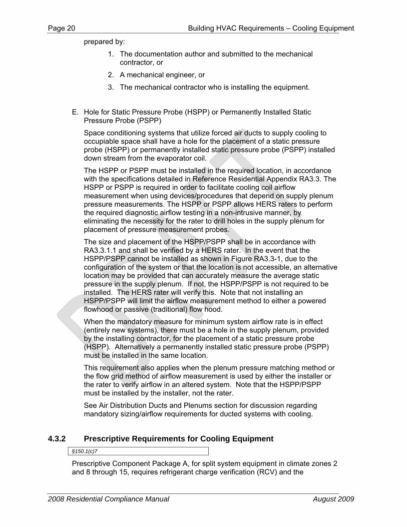
E. Hole for Static Pressure Probe (HSPP) or Permanently Installed Static Pressure Probe (PSPP)
Space conditioning systems that utilize forced air ducts to supply cooling to occupiable space shall have a hole for the placement of a static pressure probe (HSPP) or permanently installed static pressure probe (PSPP) installed down stream from the evaporator coil.
The HSPP or PSPP must be installed in the required location, in accordance with the specifications detailed in Reference Residential Appendix RA3.3. The HSPP or PSPP is required in order to facilitate cooling coil airflow measurement when using devices/procedures that depend on supply plenum pressure measurements. The HSPP or PSPP allows HERS raters to perform the required diagnostic airflow testing in a non-intrusive manner, by eliminating the necessity for the rater to drill holes in the supply plenum for placement of pressure measurement probes.
The size and placement of the HSPP/PSPP shall be in accordance with RA3.3.1.1 and shall be verified by a HERS rater. In the event that the HSPP/PSPP cannot be installed as shown in Figure RA3.3-1, due to the configuration of the system or that the location is not accessible, an alternative location may be provided that can accurately measure the average static pressure in the supply plenum. If not, the HSPP/PSPP is not required to be installed. The HERS rater will verify this. Note that not installing an HSPP/PSPP will limit the airflow measurement method to either a powered flowhood or passive (traditional) flow hood.
When the mandatory measure for minimum system airflow rate is in effect (entirely new systems), there must be a hole in the supply plenum, provided by the installing contractor, for the placement of a static pressure probe (HSPP). Alternatively a permanently installed static pressure probe (PSPP) must be installed in the same location.
This requirement also applies when the plenum pressure matching method or the flow grid method of airflow measurement is used by either the installer or the rater to verify airflow in an altered system. Note that the HSPP/PSPP must be installed by the installer, not the rater.
See Air Distribution Ducts and Plenums section for discussion regarding mandatory sizing/airflow requirements for ducted systems with cooling.
4.3.2 Prescriptive Requirements for Cooling Equipment §150.1(c)7
Prescriptive Component Package A, for split system equipment in climate zones 2 and 8 through 15, requires refrigerant charge verification (RCV) and the

Building HVAC Requirements – Cooling Equipment Page 21
2008 Residential Compliance Manual August 2009
installation of a measurement access hole (MAH). The RCV must be performed by the installer and/or HERS rater. The MAH provides a non-intrusive means of measuring return air temperature, which is a parameter important to the RCV process. The alternative to RCV is the installation of a refrigerant charge indicator display (§151(f)7Aia).
A. Refrigerant Charge Verification (RCV)
Note: The Refrigerant Charge Verification process is discussed in greater detail later in Section 4.9.
The prescriptive standards require that a HERS rater verify that air-cooled air conditioners and air-source heat pumps have the correct refrigerant charge. The RCV procedures are documented in Reference Residential Appendix RA3.2, and RA1.2.
Ensuring correct refrigerant charge can significantly improve the performance of air conditioning equipment. Refrigerants are the working fluids in air conditioning and heat pump systems that absorb heat energy from one area (the evaporator),transfer and reject it to another (the condenser).
Refrigerant charge refers to the actual amount of refrigerant present in the system. Excessive refrigerant charge (overcharge) reduces system efficiency and can lead to premature compressor failure. Insufficient refrigerant charge (undercharge) also reduces system efficiency and can cause compressors to overheat.
B. Measurement Access Hole (MAH)
MAH provide a non-intrusive means for refrigerant charge verification by HERS raters and other third party inspectors, since they eliminate the need for the raters/inspectors to drill holes into the installed air conditioning equipment enclosures for placement of the temperature sensors that are required by the refrigerant charge verification test procedures described in the Reference Residential Appendix RA3.2.
Installation of MAH must be performed by the installer of the air conditioner or heat pump equipment according to the specifications given in Reference Residential Appendix RA3.2.
The MAH feature consists of one 5/8 inch (16 mm) diameter hole in the return plenum, upstream from the evaporator coil (see figure RA3.2-1 in Reference Residential Appendix RA3.2).
C. Charge Indicator Display
The installation of a charge indicator display (CID), may be used as an alternative to the prescriptive requirement for HERS diagnostic testing of the refrigerant charge in split system air conditioners and heat pumps. The purpose of the CID is to provide real-time information to the building occupant about the status of the system refrigerant charge, metering device, and cooling coil airflow. The CID will monitor and determine the operating performance of split system air conditioners and heat pumps, and provide visual indication to the system owner or operator if the system’s refrigerant charge, airflow, or metering device performance does not conform to approved target parameters for minimally efficient operation. Thus, if the CID

Page 22 Building HVAC Requirements – Cooling Equipment
2008 Residential Compliance Manual August 2009
signals the owner/occupant that the system requires service or repair, the occupant can immediately call for a service technician to make the necessary adjustments or repairs. A CID can provide significant benefit to the owner/occupant by alerting the owner/occupant to the presence of inefficient operation that could result in excessive energy use/costs over extended periods of time. A CID can also indicate system performance faults that could result in system component damage or failure if not corrected, thus helping the owner/occupant to avoid unnecessary repair costs.
The CID procedures are documented in Reference Residential Appendix RA4.3.2.
Charge indicator display technologies shall be factory installed or field installed according to manufacturer's specifications. Reference Joint Appendix JA6 contains more information about CID technologies.
The presence of a CID on a system must be field verified by a HERS rater. See Reference Residential Appendix RA3.4.2 for the HERS verification procedure, which consists of a visual verification of the presence of the installed CID technology. The rater must inspect to see that the visual indication display component of the installed CID technology is mounted adjacent to the split system's thermostat. When the outdoor temperature is greater than 55°F, the rater must also observe that the system reports no system faults when the system is operated continuously for at least 15 minutes when the indoor air temperature returning to the air conditioner is at or above 70°F. When the outdoor temperature is below 55°F the Rater must observe that the CID does a self diagnosis and indicates that the sensors and internal processes are operating properly.
4.3.3 Performance Compliance Options for Cooling Equipment There are several options for receiving compliance credit related to the cooling system. These credits are available through the performance compliance method.
A. High Efficiency Air Conditioner
Air conditioner efficiencies are determined according to federal test procedures. The efficiencies are reported in terms of Seasonal Energy Efficiency Rating (SEER) and Energy Efficiency Rating (EER). Savings can be achieved by choosing an air conditioner that exceeds the minimum efficiency requirements.
The EER is the full load efficiency at specific operating conditions. It is possible that two units with the same SEER can have different EERs. In cooling climate zones of California, for two units with a given SEER, the unit with the higher EER is more effective in saving energy. Using the performance compliance method, credit is available for specifying an air conditioner with an EER greater than 10 (see the compliance program vendor’s compliance supplement). When credit is taken for a high EER or SEER, field verification by a HERS rater is required (see Reference Residential Appendix RA3.4).
B. Air Handler Watt Draw and Cooling Coil Airflow

Building HVAC Requirements – Page 23
2008 Residential Compliance Manual August 2009
It is mandatory that central forced air systems produce fan watt draws less than or equal to 0.58 watts/CFM and flow at least 350 CFM per nominal cooling ton. Performance compliance credits are available for demonstrating the installation of a high efficiency system with a lower fan wattage and/or higher airflow than the mandatory requirements. These credits can be achieved by selecting good duct design and can be assisted by a high efficiency fan. There are two possible performance compliance credits:
1. The performance compliance method allows the user’s proposed fan watt draw to be entered and credit earned if it is lower than the default of 0.58 watts per CFM of cooling coil airflow. To obtain this credit, the cooling coil airflow must meet the mandatory requirement of at least 350 CFM/ton of nominal cooling capacity.
2. The performance compliance method allows the user’s proposed airflow to be entered and credit earned if it is higher than the default of 350 CFM/ton of nominal cooling capacity. To obtain this credit, the fan watt draw must meet the mandatory requirement of no more than 0.58 Watts per CFM of nominal cooling capacity.
After installation, the contractor must test the actual fan power and airflow of the system using the procedure in Reference Residential Appendix RA3.3, and show that it is equal or better than what was proposed in the compliance software analysis.
Field verification by a HERS rater is required (see Reference Residential Appendix RA3.3).
4.4 Air Distribution System Ducts, Plenums, and Fans Air distribution system performance can have a big impact on overall HVAC system efficiency. Therefore, air distribution systems face a number of mandatory measures and prescriptive requirements, discussed below.
The 2013 Standards specify mandatory requirements for air distribution ducts to be sealed and tested in all climate zones. There are also a number of compliance credits available related to duct system design.
Duct efficiency is affected by the following parameters:
1. Duct location (attic, crawlspace, basement, inside conditioned space, or other)
2. Specific conditions in the unconditioned space, e.g., presence of a radiant barrier
3. Duct insulation characteristics
4. Duct surface area, and
5. Air leakage of the duct system
In performance calculations, duct efficiency can be calculated in one of two ways:
1. default input assumptions; or
2. diagnostic measurement values.

Page 24 Building HVAC Requirements – Air Distribution System Ducts, Plenums, and Fans
2008 Residential Compliance Manual August 2009
The computer program will use default assumptions for the proposed design when the user does not intend to make improvements in duct efficiency.
4.4.1 Mandatory Measures for Air Distribution System Ducts, Plenums and Fans
A. Minimum Insulation §150.0(m)1
In all cases, unless ducts are enclosed entirely in directly conditioned space, the minimum allowed duct insulation value is R-6. Note that higher values may be required by the prescriptive requirements as described below.
To determine whether ducts are enclosed entirely in directly conditioned space, a rater must field verify by using the protocols of RA3.1.4.3.8. This can include ducts located in the floor joist area between conditioned floors.
RA3.1.4.3.8 utilizes a duct leakage to outside test procedure to help ensure that the ducts are within the pressure boundary of the space being served by the duct system. Passing the test alone is not enough to establish that the ducts are entirely within conditioned space. The test procedure is in addition to a basic visual inspection of the ducts to ensure that no portion of the duct system is obviously outside of the apparent pressure/thermal boundary. Once this has been established, the leakage to outside test verifies that the pressure boundary is intact and preventing leakage from escaping to the outside.
Applying this procedure to multi-family dwelling units poses a unique situation. In this case leakage to “outside” means conditioned air leaking from the ducts to anywhere outside of the pressure boundary of the space being served by the duct system, including adjacent dwelling units. Duct leakage to adjacent dwelling units is not desirable and should be eliminated. When performing the leakage to outside test, it is only necessary to pressurize the dwelling unit served by the duct system being tested.
§150.0(m)5
For the purpose of determining installed R-value of duct insulation based on thickness, when not an integral part of a manufacturer-labeled, insulated duct product such as vinyl flex duct, the following shall be used:
1. For duct wrap, the installed thickness of insulation must be assumed to be 75 percent of the nominal thickness due to compression.
2. For duct board, duct liner and factory-made rigid ducts not normally subjected to compression, the nominal insulation thickness shall be used.
B. Connections and Closures §150.0(m)1, §150.0(m)2, §150.0(m)3
Note: The Duct Installation Standards are discussed in more detail in Section

Building HVAC Requirements – Air Distribution System Ducts, Plenums, and Fans Page 25
2008 Residential Compliance Manual August 2009
4.4.5.
The Standards set a number of mandatory measures related to duct connections and closures. These measures address both the materials and methods used for duct sealing. The following is a summary. Refer to the sections of the Standards listed above for additional details.
Connections between metal ducts and the inner core of flexible ducts must be mechanically fastened.
C. Factory-fabricated Duct Systems
Factory fabricated duct systems must comply with the following requirements:
1. All factory-fabricated duct systems must comply with UL 181 for ducts and closure systems, including collars, connections, and splices, and be labeled as complying with UL 181. UL181 testing may be performed by UL laboratories or a laboratory approved by the Executive Director.
2. All pressure-sensitive tapes, heat-activated tapes, and mastics used in the manufacture of rigid fiberglass ducts must comply with UL 181 and UL 181A.
3. All pressure-sensitive tapes and mastics used with flexible ducts must comply with UL 181 and UL 181B.
4. Joints and seams of duct systems and their components cannot be sealed with cloth back rubber adhesive duct tapes unless such tape is used in combination with mastic and draw bands: or
5. It has on its backing the phrase "CEC approved," a drawing of a fitting to plenum joint in a red circle with a slash through it (the international symbol of prohibition), and a statement that it cannot be used to seal fitting to plenum and junction box joints.
D. Field-fabricated Duct Systems
Field –fabricated duct systems must comply with the following requirements:
1. Factory-made rigid fiberglass and flexible ducts for field-fabricated duct systems must comply with UL 181.All pressure-sensitive tapes, mastics, aerosol sealants, or other closure systems used for installing field-fabricated duct systems shall meet the applicable requirements of UL 181, UL 181A, and UL 181B.
2. Mastic sealants and mesh.
3. Sealants must comply with the applicable requirements of UL 181, UL 181A, and/or UL 181B, and be nontoxic and water resistant.
4. Sealants for interior applications must be tested in accordance with ASTM C731 and D2202.
5. Sealants for exterior applications must be tested in accordance with ASTM C731, C732, and D 2202.
6. Sealants and meshes must be rated for exterior use.

Page 26 Building HVAC Requirements – Air Distribution System Ducts, Plenums, and Fans
2008 Residential Compliance Manual August 2009
7. Pressure-sensitive tape. Pressure-sensitive tapes must comply with the applicable requirements of UL 181, UL 181A, and UL 181B.
8. Joints and seams of duct systems and their components must not be sealed with cloth back rubber adhesive duct tapes unless such tape is used in combination with mastic and draw bands: or
9. It has on its backing the phrase "CEC approved," a drawing of a fitting to plenum joint in a red circle with a slash through it (the international symbol of prohibition), and a statement that it cannot be used to seal fitting to plenum and junction box joints.
E. Draw Bands Used With Flexible Duct
1. Draw bands must be either stainless-steel worm-drive hose clamps or UV-resistant nylon duct ties.
2. Draw bands must have a minimum tensile strength rating of 150 pounds.
3. Draw bands must be tightened as recommended by the manufacturer with an adjustable tensioning tool.
F. Aerosol-sealant Closures
1. Aerosol sealants shall meet the requirements of UL 723 and be applied according to manufacturer specifications.
2. Tapes or mastics used in combination with aerosol sealing shall meet the requirements of this Section.
If mastic or tape is used to seal openings greater than 1/4 inch, the combination of mastic and either mesh or tape must be used.
Building spaces such as cavities between walls, support platforms for air handlers, and plenums defined or constructed with materials other than sealed sheet metal, duct board, or flexible duct must not be used for conveying conditioned air including return air and supply air. The practice of using drywall materials as the interior surface of a return plenum is not allowed. Building cavities and support platforms may contain ducts. Ducts installed in cavities and support platforms must not be compressed to cause reductions in the cross sectional area of the ducts. Although a HERS rater may examine this as a part of his or her responsibilities when involved in a project, the enforcement of these minimum standards for ducts is the responsibility of the building official.
Example 4-1
Question
I am installing a fan coil in the hallway of a multifamily dwelling unit in a space constructed of sheetrock. The sheetrocked space is formed by the original hallway ceiling at the top, the hallway sidewalls, and sheetrock across the bottom of the space with a return grill mounted in the bottom sheetrock. Does a duct have to be installed connecting the fan coil return to the return register?
Answer
This type of installation may be used only when a fan-coil unit is installed in a sheetrocked space that is constructed and sealed to meet all applicable requirements in the California Building Code (CBC) Title 24, Part 2, Volume 1, Chapter 7 for fire-resistance-rated construction.

Building HVAC Requirements – Air Distribution System Ducts, Plenums, and Fans Page 27
2008 Residential Compliance Manual August 2009
Also, §150(m) states as follows:
“Building cavities, support platforms for air handlers, and plenums defined or constructed with materials other than sealed sheet metal, duct board or flexible duct shall not be used for conveying conditioned air.”
There are two acceptable methods of complying with §150(m) for the fan coil space that is the subject of the question.
1. A return duct is installed between the fan coil and the return register.
2. If the builder demonstrates that the sheetrocked space in which the fan coil is installed is not a plenum, the duct in method “1” is not required.
The California Mechanical Code has the following definition of a plenum:
“PLENUM is an air compartment or chamber including uninhabited crawl spaces, areas above ceilings or below a floor, including air spaces below raised floors of computer/data processing centers, or attic spaces, to which one or more ducts are connected and which forms part of either the supply air, return air or exhaust air system, other than the occupied space being conditioned.”
To demonstrate the sheetrocked space in which the fan coil is installed is not a plenum, the builder must demonstrate that it is part of the conditioned space. This fan coil space can be considered part of the conditioned space if it is demonstrated that the space
1. is within the building envelope, and
2. air leakage pathways (e.g., infiltration connections to building cavities) are sealed such that the space is more connected to the inside of the envelope than to outside the envelope.
There are two ways of demonstrating that air leakage pathways are properly sealed.
1. The easiest way is to construct the fan coil space so that an inspector is able to visually determine that the space has no leakage paths. No testing is required for this approach. The inspector must be able to inspect all joints and seams in the sheetrock, particularly horizontal seams that are above and below the sheetrocked bottom of the space, and to verify that no horizontal seams are behind the sheetrocked bottom or the mounting supports for the sheetrocked bottom of the space. The supports for the sheetrocked bottom must be mounted on the surface of the walls of the space and have sheetrock between the support and the wall framing.
Any horizontal seam in the wall-mounted sheetrock must be a minimum of ½ inch below the lower surface of the sheetrocked bottom. Also any horizontal seam in the wall of the space above the sheetrocked bottom must be a minimum of 1½ inches above the top of the mounting wood or metal brackets. This spacing is required to allow adequate room for taping the seam. All vertical sheetrock seams must be taped and sealed with joint compound or equivalent prior to the installation of the wood or metal brackets that support the dropped ceiling.
All penetrations of this space, for example refrigerant lines, water lines for hydronic heating, electrical (line and low voltage) lines, sprinkler lines, and ducts must be sealed with fire caulk or other approved sealing material as required by the building official.
Ductwork that penetrates the sheetrock must use a collar that goes entirely through the wall cavity. These collars must extend at least two inches past the sheetrock on each side of the wall cavity. The collars must then be sealed to the sheetrock on each side of the wall. The ducts must be attached and sealed to the collar.
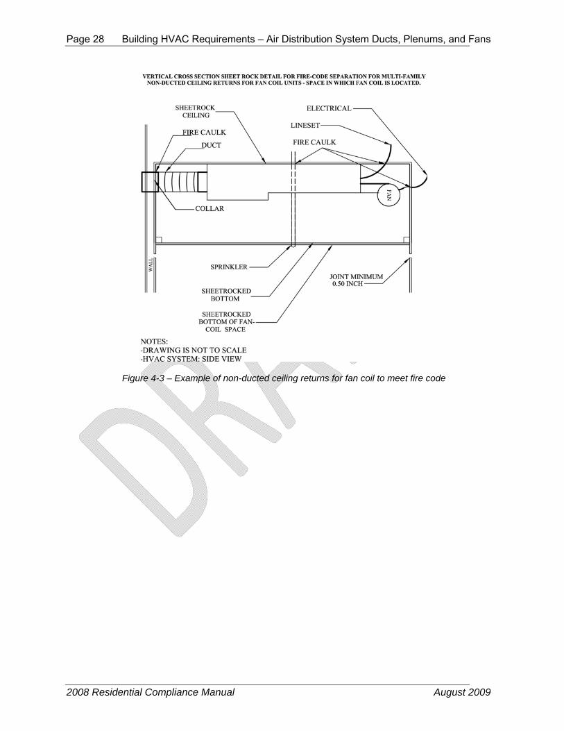
2. The other way to demonstrate there is no air leakage pathway that is more connected to the outside than to the inside is to test the leakage of the sheetrocked space as though it were a duct. For this test, the space is sealed off and tested with duct pressurization equipment at a pressure of 25 Pa. If the tested leakage from this space is 25 cfm or less, then the space may be considered to have no substantial leakage to outside the conditioned space (effectively zero within the instrumentation accuracy). The results of this test must be reported to the building official. See the following three figures.
Page 28 Building HVAC Requirements – Air Distribution System Ducts, Plenums, and Fans
2008 Residential Compliance Manual August 2009
Figure 4-3 – Example of non-ducted ceiling returns for fan coil to meet fire code

Building HVAC Requirements – Air Distribution System Ducts, Plenums, and Fans Page 29
2008 Residential Compliance Manual August 2009
Figure 4-4 – Example of metal bracket support to meet fire code separation
§150.0(m)1 Exception to §150.0(m)1
Ducts and fans integral to a wood heater or fireplace are exempt from these insulation and installation requirements.
§150.0(m)2D, §150.0(m)3D
Duct systems may not use cloth-back, rubber-adhesive duct tape (typical, “old fashion”, non-rated duct tape) unless it is installed in combination with mastic and draw bands. Note: mastic and drawbands alone are adequate for sealing most connections. Cloth back rubber adhesive duct tape would then only be used to hold the outer vapor barrier in place or for some other superfluous purpose. It alone is not adequate to serve as an air sealing method or as a mechanical connection.
The enforcement of these minimum standards is normally the responsibility of the building official, however HERS raters will also verify compliance with this requirement in conjunction with duct leakage verification.

Page 30 Building HVAC Requirements – Air Distribution System Ducts, Plenums, and Fans
2008 Residential Compliance Manual August 2009
G. Product Markings §150.0(m)2A, §150.0(m)6
All factory-fabricated duct systems must meet UL 181 for ducts and closure systems and be labeled as complying with UL 181. Collars, connections and splices are considered to be factory-fabricated duct systems and must meet the same requirement.
Insulated flexible duct products installed to meet this requirement must include labels, in maximum intervals of 3 ft, showing the R-value for the duct insulation (excluding air films, vapor barriers, or other duct components), based on the tests and thickness specified in §150(m).
H. Dampers to Prevent Air Leakage §150.0(m)7
Fan systems that exhaust air from the building to the outside must be provided with back draft or automatic dampers.
§150.0(m)8
Gravity ventilating systems must have an automatic or readily accessible, manually operated damper in all openings to the outside, except combustion inlet and outlet air openings and elevator shaft vents. This includes clothes dryer exhaust vents when installed in conditioned space.
I. Protection of Insulation §150.0(m)9
Insulation must be protected from damage, including that due to sunlight, moisture, equipment maintenance, and wind but not limited to the following:
• Insulation exposed to weather must be suitable for outdoor service; for example, protected by aluminum, sheet metal, painted canvas, or plastic cover.
• Cellular foam insulation shall be protected as above or painted with a coating that is water retardant and provides shielding from solar radiation that can cause degradation of the material.
J. Ducts in Concrete Slab
Ducts located in a concrete slab must have R-6 insulation but other issues will come into play. If ducts are located in the soil beneath the slab or embedded in the slab, the insulation material should be designed and rated for such installation. Insulation installed in below-grade applications should resist moisture penetration (closed cell foam is one moisture-resistant product). Common pre-manufactured duct systems are not suitable for below-grade installations. If concrete is to be poured directly over the ducts, then the duct construction and insulation system should be sturdy enough to resist the pressure and not collapse. Insulation should be of a type that will not compress, or it should be located inside a rigid duct enclosure. The only time that common flex ducts are suitable in a below-grade application is when a channel is provided in the slab.

Building HVAC Requirements – Air Distribution System Ducts, Plenums, and Fans Page 31
2008 Residential Compliance Manual August 2009
K. Porous Inner Core Flex Duct §150(m)10
Over time the outer vapor barrier of flex duct can be compromised. Therefore porous inner core flex duct is not allowed.
L. Duct System Sealing and Leakage Testing §150(m)11
Duct system sealing and leakage testing is mandatory in all climate zones as specified in the 2013 Standards. Duct systems in newly constructed single family dwellings, towhouses, and multifamily dwellings are required to comply with the requirements. Alterations and additions to ducted systems in existing buildings in all climate zones are also required to comply with applicable maximum leakage criteria. Refer to Chapter 9 for more information on duct sealing and leakage testing for existing buildings.
M. Air Filtration §150.0(m)12
Air filtration is present in forced air systems to protect the equipment and may provide health benefits to occupants of the building. In addition to filtering particulates from the airstream filters add flow resistance to the forced air system, potentially lowering the efficiency of the heating/cooling equipment. Flow resistance is measured as a pressure drop at a specific airflow.
Except for evaporative coolers, any mechanical forced air heating and/or cooling system with more than 10 feet of duct must meet four sets of criteria:
1. System Design Criteria:
a) All recirculated and outdoor air passing through the heating/cooling device must first pass through the filter.
b) The system design must accommodate the pressure drop through the filter at the designed airflow. In order to accomplish this, the design airflow and the design pressure drop through the filter must be determined by the designer. The design pressure drop will determine the size and depth of the filter media required for the device (return filter grill or filter rack).
c) If the system design elects compliance utilizing the Return Duct Design alternative specified in Tables 150.0-C and D, then the designer must assume a design filter pressure drop of 0.05 IWC at the applicable design airflow rate.
d) Replacing the filters, like for like, when they become dirty brings their resistance to airflow back to the design condition. Therefore, the filters must be located to allow access for regular service by the occupants.
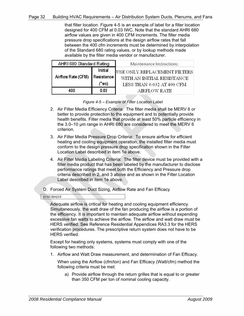
e) To maintain the energy efficiency of the system it is necessary for the occupants to know which filters to select that will provide the designed airflow. Therefore, a clearly legible label, such as shown in Figure 4-5 shall be permanently placed in a location visible to a person changing the filter. As shown in Figure 4-5, the label shows the allowable maximum resistance at the airflow rate closest to the design airflow for
Page 32 Building HVAC Requirements – Air Distribution System Ducts, Plenums, and Fans
2008 Residential Compliance Manual August 2009
that filter location. Figure 4-5 is an example of label for a filter location designed for 400 CFM at 0.03 IWC. Note that the standard AHRI 680 airflow values are given in 400 CFM increments. The filter media pressure drop specifications at the design airflow rates that fall between the 400 cfm increments must be determined by interpolation of the Standard 680 rating values, or by lookup methods made available by the filter media vendor or manufacturer.
Figure 4-5 – Example of Filter Location Label
2. Air Filter Media Efficiency Criteria: The filter media shall be MERV 6 or better to provide protection to the equipment and to potentially provide health benefits. Filter media that provide at least 50% particle efficiency in the 3.0–10 μm range in AHRI 680 are considered to meet the MERV 6 criterion.
3. Air Filter Media Pressure Drop Criteria: To ensure airflow for efficient heating and cooling equipment operation, the installed filter media must conform to the design pressure drop specification shown in the Filter Location Label described in item 1e above.
4. Air Filter Media Labeling Criteria: The filter device must be provided with a filter media product that has been labeled by the manufacturer to disclose performance ratings that meet both the Efficiency and Pressure drop criteria described in 2, and 3 above and as shown in the Filter Location Label described in item 1e above.
D. Forced Air System Duct Sizing, Airflow Rate and Fan Efficacy §150.0(m)13
Adequate airflow is critical for heating and cooling equipment efficiency. Simultaneously, the watt draw of the fan producing the airflow is a portion of the efficiency. It is important to maintain adequate airflow without expending excessive fan watts to achieve the airflow. The airflow and watt draw must be HERS verified. See Reference Residential Appendices RA3.3 for the HERS verification procedures. The prescriptive return system does not have to be HERS verified.
Except for heating only systems, systems must comply with one of the following two methods:
1. Airflow and Watt Draw measurement, and determination of Fan Efficacy.
When using the Airflow (cfm/ton) and Fan Efficacy (Watt/cfm) method the following criteria must be met:
a) Provide airflow through the return grilles that is equal to or greater than 350 CFM per ton of nominal cooling capacity.

Building HVAC Requirements – Air Distribution System Ducts, Plenums, and Fans Page 33
2008 Residential Compliance Manual August 2009
b) At the same time the fan watt draw must be less than or equal to 0.58 Watts per CFM.
The methods of measuring the watt draw are described in Reference Residential Appendix RA3.3. They use one of three acceptable apparati:
a) a portable watt meter,
b) an analog utility revenue meter, or
c) a digital utility revenue meter.
There are three acceptable methods to determine compliance with the cooling coil airflow requirement. They are described in Reference Residential Appendix RA3.3 and use an:
a) active or passive flow capture hood to measure the total airflow through the return grill(s), or
b) flow grid device(s) at the return grill(s) or other location where all the central fan airflow passes through the flow grid, or
c) fan flow meter device to perform the plenum pressure matching procedure.
The flow grid measurement device and the fan flow meter measurement device both require access to static pressure measurements of the airflow exiting the cooling coil, which utilizes a HSPP or PSPP (Section RA3.3.1.1).
The contractor must install either a hole for the placement of a static pressure probe (HSPP) or provide a permanently installed static pressure probe (PSPP) as shown in Figure 4-XXX below and Reference Residential Appendix RA3.3

Page 34 Building HVAC Requirements – Air Distribution System Ducts, Plenums, and Fans
2008 Residential Compliance Manual August 2009
The HSPP or PSPP facilitates cooling coil airflow measurement when using devices/procedures that depend on supply plenum pressure measurements.
2. Return Duct System Design Method – This method allows the designer to specify, and the contractor to install, a system that does not have to be tested for airflow and fan watt draw. This method can be used for return systems with two returns. Each return shall be no longer than 30 feet from the return plenum to the filter grille. When bends are needed, metal elbows are desirable. Each return can have up to 180 degrees of bend and no more 90 degrees of bend can be flex duct. To use this method, the designer and installer must provide return system sizing that meets the appropriate criteria in Table 150.0-C or D.

Building HVAC Requirements – Air Distribution System Ducts, Plenums, and Fans Page 35
2008 Residential Compliance Manual August 2009
Two Returns System Nominal
Tonnage Return 1 Minimum
Duct Diameter (inches)
Return 2 Minimum Duct Diameter
(inches)
Minimum Gross Filter Grille Face
Area (sq. in.) 1.5 12 10 500 2.0 14 12 600 2.5 14 14 800 3.0 16 14 900 3.5 16 16 1000 4.0 18 18 1200 5.0 20 20 1500
This method also gives the designer the option of specifying the filter location labels (Section M1d above) and filter media (Section M2b above) based on a 0.05 IWC filter pressure drop at the assumed airflow shown in Table 4–XXX.
Two Return Systems System Nominal Tonnage
Return 1 Minimum Duct
Diameter (inches)
Return 1 Assumed Filter
Flow (CFM)
Return 2 Minimum Duct
Diameter (inches)
Return 2 Assumed Filter
Flow (CFM)
1.5 12 350 10 250 2.0 14 500 12 350 2.5 14 500 14 500 3.0 16 700 14 500 3.5 16 700 16 700 4.0 18 800 18 800 5.0 20 1000 20 1000
N. Zonally Controlled Central Forced Air Cooling Systems §150(m)15
The primary purpose of zoning ducted air conditioners, heat pumps, and furnaces is to improve comfort. Increased comfort is attained by having the capacity of the HVAC system (cooling or heating delivered) follow the shift in load as it changes across the house. For example, it is common for two-story homes to be too hot on the second floor in both summer and winter. Zoning has the capability of diverting more of the HVAC capacity to the area with the increased load. Another common example is a home with a significant area of west-facing and east-facing windows. In the summer, the east rooms overheat in the morning and the west rooms overheat in the afternoon.
Providing the most agreeable temperature to all the zones is comfortable, but it carries with it the distinct possibility of increased energy consumption. Since the most common home is single zoned and has only one thermostat placed near the center of the house, temperatures in the rooms distant from that thermostat will vary, sometimes significantly. If zoning is added, the more distant rooms may be conditioned to a more comfortable temperature. This increased conditioning requires more energy.

Page 36 Building HVAC Requirements – Air Distribution System Ducts, Plenums, and Fans
2008 Residential Compliance Manual August 2009
It is common for ducted zoned systems to produce lower airflow through the returns thus lowering the sensible efficiency of the heating or cooling equipment. There are two primary methods by which the common multi-zoned dampered system lowers airflow: additional restriction of zoning dampers and recirculation through the air conditioner from a bypass duct. To avoid this efficiency problem, ducted zoned systems utilizing a single speed air conditioner must simultaneously meet the following criteria;
a In every zonal control mode, the system shall provide airflow through the return grilles that is equal to or greater than 350 CFM per ton of nominal cooling capacity.
b In every zonal control mode, the fan watt draw must be less than or equal to 0.58 Watts per CFM.
The airflow and fan watt draw must be HERS verified. See Reference Residential Appendix RA3.3 for the HERS verification procedures.
Zonally controlled central forced air cooling systems with multi-speed or variable speed compressors only need to be verified to meet the above 350 CFM per nominal ton and 0.58 Watts per CFM criteria with the compressor on high speed and all zones calling for cooling.
O. Indoor Air Quality and Mechanical Ventilation §150.0(o)
See Section 4.6 of this chapter for details.
4.4.1 Prescriptive Requirements for Air Distribution System Ducts, Plenums and Fans
A. Duct Insulation
§150.1(c)9
All ducts shall either be in directly conditioned space as confirmed by field verification and diagnostic testing in accordance with RA3.1.4.3.8 (leakage to outside) or be insulated to a minimum installed level as specified by Table 150.1-A, which requires either R-6 or R-8 depending on the climate zone. (Climate zones 1-10, 12, and 13 require R-6 and climate zones 11, and 14-16 require R-8.) Since R-6 is the mandatory minimum, only the R-8 requirement can be opted out of by using the performance approach and trading off the energy penalty against some other features.
B. Central Fan Integrated (CFI) Ventilation
There is a prescriptive requirement for ducted systems that have cooling and a CFI ventilation system to have the fan efficacy verified. This can be opted out of using the performance approach.

Building HVAC Requirements – Air Distribution System Ducts, Plenums, and Fans Page 37
2008 Residential Compliance Manual August 2009
Figure 4-1 – R-4.2, R-6, and R-8 Ducts
4.4.2 Compliance Options for Air Distribution System Ducts, Plenums and Fans
The Standards provide credit for several compliance options related to duct design and construction..
A. Cooling Coil Airflow and Fan Efficacy
A performance compliance credit is available for demonstrating the installation of a high efficiency fan and duct system with better performance than the mandatory requirement of 350 cfm/ton and 0.58 watts/cfm. This credit can be achieved by selecting a unit with a high efficiency air handler fan and/or careful attention to efficient duct design. The performance compliance method allows the user’s proposed fan power to be entered into the program, and credit will be earned if it is lower than the default of 0.58 watts per CFM of cooling coil airflow. To obtain this credit, the cooling coil airflow must meet the prescriptive requirements of at least 350 CFM/ton of nominal cooling capacity. After installation, the contractor must test the actual fan power of each system using the procedure in Reference Residential Appendix RA3.3, and show that it is equal or less than what was proposed in the compliance software analysis.
The watt draw and airflow must also be verified by a HERS rater.
B. Supply Duct Location
There are three ways to achieve credit for favorable duct location when using the performance compliance method.
First, credit is available if no more than 12 LF (linear feet) of supply duct are outside conditioned space. This total must include the air handler and plenum length. This credit results in a reduction of duct surface area in the computer compliance programs. This option requires certification by the installer and field verification by a HERS rater.
Page 38 Building HVAC Requirements – Air Distribution System Ducts, Plenums, and Fans
2008 Residential Compliance Manual August 2009
The second alternative applies when 100 percent of the supply ducts are located in either the crawlspace or the basement rather than in the attic. To achieve this credit, a duct layout must be included in the plans showing that all supply registers are located in the floor (or at least no more than 2 ft above the floor). The compliance software will include this measure on the Certificate of Compliance in the Special Features Inspection Checklist. This option does not require field verification by a HERS rater.
Third, credit for a high efficiency duct design is available through the Diagnostic Supply Duct Location, Surface Area, and R-value compliance option, which is described below. This option requires field verification of the duct design layout drawing(s) by a HERS rater. Verified duct design, when required, will be included in the HERS Required Verification list on the Certificate of Compliance (CF-1R). This approach provides energy savings credits for having shorter duct runs, fewer ducts, ducts in beneficial locations of ductwork and other benefits of a well designed duct system.
There is no compliance credit provided for choosing a heating system such as a wall furnace, floor heater, or room heater even though those systems typically have no ducts. For these cases, the standard design in the compliance calculation uses the same type of system and also has no ducts. However, other systems, such as hydronic heating systems with a central heater or boiler and multiple terminal units, are considered central HVAC systems that are compared to a ducted system in the Standard Design. If the hydronic system has no ducts, there may be a significant energy credit through the performance method.

Building HVAC Requirements – Air Distribution System Ducts, Plenums, and Fans Page 39
2008 Residential Compliance Manual August 2009
Figure 4-2 – Example: Buried Ducts on Ceiling and Deeply Buried Ducts
C. Duct Insulation
Performance credit is also available if all of the ducts are insulated to a level higher than required by the prescriptive package. If ducts with multiple R-values are installed, the lowest duct R-value must be used for the entire duct system. However, the air handler, plenum, connectors, and boots can be insulated to the mandatory minimum R-value.
As an alternative when there is a mix of duct insulation R-values, credit is available through the method described in the next section.
D. Diagnostic Supply Duct Location, Surface Area, and R-value
This compliance option allows the designer to take credit for a high efficiency duct design that incorporates duct system features that may not meet the criteria for the duct location and/or insulation compliance options described above. This method requires that the designer must enter the design characteristics of all supply ducts that are not located within conditioned space. The information required for the input to the compliance software includes the length, diameter, insulation R-value, and location of all supply ducts. This method will result in a credit if the proposed duct system is better
Page 40 Building HVAC Requirements – Air Distribution System Ducts, Plenums, and Fans
2008 Residential Compliance Manual August 2009
than the standard design, which exactly meets the prescriptive insulation requirement and has supply duct surface area set at 27 percent of floor area.
In order to claim this credit, the duct system design must be documented on plans that are submitted to the enforcement agency and posted at the construction site for use by the installation persons, the enforcement agency field inspector, and the HERS rater. The duct system must be installed in accordance with the approved duct system plans, and the duct system installation must be certified by the installer on the CF-6R form and verified by a HERS rater on the CF-4R form. Details of this compliance option are described in Section 3.12.3 of the Residential ACM Manual, and verification procedures are described in RA3.1 of the Reference Residential Appendix.
This compliance option also allows credit for the special case of ducts that are buried by blown attic insulation. For ducts that lie on the ceiling (or within 3.5 inch of the ceiling), the effective R-value is calculated based on the duct size and the depth of ceiling insulation as shown in Table R3-38 in the Residential ACM Manual. This case is referred to as “Buried Ducts on the Ceiling”. For the case of Deeply Buried Ducts, which are ducts that are enclosed in a lowered portion of the ceiling and completely covered by attic insulation, then the effective R-value allowance in the compliance calculations is R-25 when the attic insulation is fiberglass and R-31 for cellulose attic insulation. In order to take credit for buried ducts, the system must meet the verified duct design criteria described above, be diagnostically tested for duct sealing compliance by a HERS rater according to Reference Residential Appendix RA3.1, and meet the requirements for high insulation installation quality described in Reference Residential Appendix RA3.5. Verified minimum airflow (350 cfm/ton or higher if higher is specified on the CF-1R) is required when a measure is selected for compliance that has a verified duct design as a prerequisite.
E. Ducts in Attics with Radiant Barriers
Installation of a radiant barrier in the attic increases the duct efficiency by lowering attic summer temperatures. Compliance credit for radiant barriers requires listing of the radiant barrier in the Special Features and Modeling Assumptions in order to aid the local enforcement agency’s inspections. Compliance credit for a radiant barrier does not require HERS rater verification.
4.4.3 Duct Installation Standards The mandatory duct construction measures referenced in Section 4.4.1 above state that duct installations must comply with 2007 California Mechanical Code Sections 601, 602, 603, 604, 605, and the applicable requirements of the 2013 California Building Energy Efficiency Standards. Some of the highlights of these requirements are listed in this section along with some guidance for recommended quality construction practice.
A. Tapes and Clamps
All tapes and clamps must meet the requirements of §150(m).
Cloth-back rubber-adhesive tapes must be used only in combination with mastic and draw bands, or have on its backing the phrase "CEC approved," a

Building HVAC Requirements – Air Distribution System Ducts, Plenums, and Fans Page 41
2008 Residential Compliance Manual August 2009
drawing of a fitting to plenum joint in a red circle with a slash through it (the international symbol of prohibition), and a statement that it cannot be used to seal fitting to plenum and junction box joints.
B. All Joints Must Be Mechanically Fastened
For residential round metal ducts, installers must overlap the joint by at least 1½ inch and use three sheet metal screws equally spaced around the joint (see Figure 4-3).
Source: Richard Heath & Associates/Pacific Gas & Electric
Figure 4-3 – Connecting Round Metallic Ducts
For round non-metallic flex ducts, installers must insert the core over the metal collar or fitting by at least 1 in. This connection may be completed with either mesh, mastic and a clamp, or two wraps of tape and a clamp.
For the mesh and mastic connection, the installer must first tighten the clamp over the overlapping section of the core, apply a coat of mastic covering both the metal collar and the core by at least 1 in., and then firmly press the fiber mesh into the mastic and cover with a second coat of mastic over the fiber mesh (see Figure 4-4).
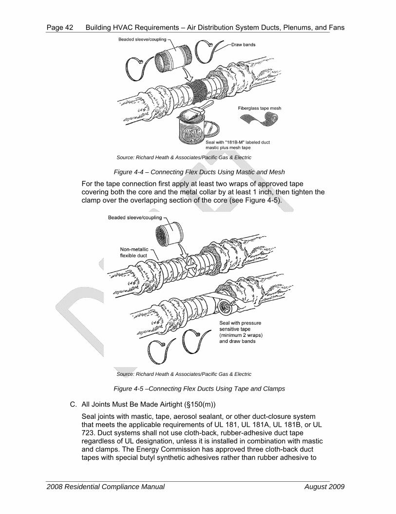
Page 42 Building HVAC Requirements – Air Distribution System Ducts, Plenums, and Fans
2008 Residential Compliance Manual August 2009
Source: Richard Heath & Associates/Pacific Gas & Electric
Figure 4-4 – Connecting Flex Ducts Using Mastic and Mesh
For the tape connection first apply at least two wraps of approved tape covering both the core and the metal collar by at least 1 inch, then tighten the clamp over the overlapping section of the core (see Figure 4-5).
Source: Richard Heath & Associates/Pacific Gas & Electric
Figure 4-5 –Connecting Flex Ducts Using Tape and Clamps
C. All Joints Must Be Made Airtight (§150(m))
Seal joints with mastic, tape, aerosol sealant, or other duct-closure system that meets the applicable requirements of UL 181, UL 181A, UL 181B, or UL 723. Duct systems shall not use cloth-back, rubber-adhesive duct tape regardless of UL designation, unless it is installed in combination with mastic and clamps. The Energy Commission has approved three cloth-back duct tapes with special butyl synthetic adhesives rather than rubber adhesive to

Building HVAC Requirements – Air Distribution System Ducts, Plenums, and Fans Page 43
2008 Residential Compliance Manual August 2009
seal flex duct to fittings. These tapes are:
• Polyken 558CA, Nashua 558CA, manufactured by Berry Plastics Tapes and Coatings Division and
• Shurtape PC 858CA, manufactured by Shurtape Technologies, Inc.
These tapes passed Lawrence Berkeley Laboratory tests comparable to those that cloth-back rubber-adhesive duct tapes failed (the LBNL test procedure has been adopted by the American Society of Testing and Materials as ASTM E2342-03). These tapes are allowed to be used to seal flex duct to fittings without being in combination with mastic. These tapes cannot be used to seal other duct system joints, such as the attachment of fittings to plenums and junction boxes. These tapes have on their backing a drawing of a fitting to plenum joint in a red circle with a slash through it (the international symbol of prohibition) to illustrate where they are not allowed to be used, and installation instructions in their packing boxes that explain how to install them on duct core to fittings and a statement that the tapes cannot be used to seal fitting to plenum and junction box joints.
Mastic and mesh should be used where round or oval ducts join flat or round plenums (see Figure 4-6).

Page 44 Building HVAC Requirements – Air Distribution System Ducts, Plenums, and Fans
2008 Residential Compliance Manual August 2009
Source: Richard Heath & Associates/Pacific Gas & Electric
Figure 4-6 – Sealing Metallic Ducts with Mastic and Mesh
All ducts must be adequately supported.
Both rigid duct and flex duct may be supported on rigid building materials between ceiling joists or on ceiling joists.
For rigid round metal ducts that are suspended from above, hangers must occur 12 ft apart or less (see Figure 4-7).
Source: Richard Heath & Associates/Pacific Gas & Electric
Figure 4-7 – Options for Suspending Rigid Round Metal Ducts
For rectangular metal ducts that are suspended from above, hangers must occur at a minimum of 4 ft to 10 ft depending on the size of the ducts (see Table 6-2-A in Appendix A of the 2007 California Mechanical Code). Refer to Figure 4-8.

Building HVAC Requirements – Air Distribution System Ducts, Plenums, and Fans Page 45
2008 Residential Compliance Manual August 2009
Source: Richard Heath & Associates/Pacific Gas & Electric
Figure 4-8 – Options for Suspending Rectangular Metal Ducts
For flex ducts that are suspended from above, hangers must occur at 4 ft apart or less and all fittings and accessories must be supported separately by hangers (see Figure 4-9).
Source: Richard Heath & Associates/Pacific Gas & Electric
Figure 4-9 – Minimum Spacing for Suspended Flex Ducts
For vertical runs of flex duct, support must occur at 6 ft intervals or less (see Figure 4-10)

Page 46 Building HVAC Requirements – Air Distribution System Ducts, Plenums, and Fans
2008 Residential Compliance Manual August 2009
Source: Richard Heath & Associates/Pacific Gas & Electric
Figure 4-10 – Minimum Spacing for Supporting Vertical Flex Ducts
The routing and length of all duct systems can have significant impacts on system performance due to possible increased airflow resistance. The Energy Commission recommends using the minimum length of duct to make connections and the minimum possible number of turns.
For flexible duct, the Energy Commission recommends fully extending the duct by pulling the duct tight and cutting off any excess duct and avoiding bending ducts across sharp corners or compressing them to fit between framing members (see Figure 4-11). Also avoid incidental contact with metal fixtures, pipes, or conduits or installation of the duct near hot equipment such as furnaces, boilers, or steam pipes that are above the recommended flexible duct use temperature.
Source: Richard Heath & Associates/Pacific Gas & Electric
Figure 4-11 – Minimizing Radius for Flex Duct Bends
All joints between two sections of duct must be mechanically fastened and substantially airtight. For flex duct this must consist of a metal sleeve no less

Building HVAC Requirements – Controls Page 47
2008 Residential Compliance Manual August 2009
than 4 inch in length between the two sections of flex duct.
All joints must be properly insulated. For flex ducts this must consist of pulling the insulation and jacket back over the joint and using a clamp or two wraps of tape.
Aerosol sealant injection systems are an alternative that typically combines duct testing and duct sealing in one process. Figure 4-12 shows the computer-controlled injection fan temporarily connected to the supply duct. The plenum is blocked off by sheet metal to prevent sealant from entering the furnace. Supply air registers are also blocked temporarily to keep the sealant out of the house. Note that ducts must still be mechanically fastened even if an aerosol sealant system is used.
Source: Richard Heath & Associates/Pacific Gas & Electric
Figure 4-12 – Computer-Controlled Aerosol Injection System
4.5 Controls
4.5.1 Thermostats Automatic setback thermostats can add both comfort and convenience to a home. Occupants can wake up to a warm house in the winter and come home to a cool house in the summer without using unnecessary energy.
§110.2(c), §150.0(i)
A thermostat is always required for central systems whether the prescriptive or performance compliance method is used. An exception is allowed only if:
(1) the building complies using a computer performance approach with a non-setback thermostat; and
(2) the system is one of the following non-central types:
1. Non-central electric heaters

Page 48 Building HVAC Requirements –
2008 Residential Compliance Manual August 2009
2. Room air conditioners
3. Room air conditioner heat pumps
4. Gravity gas wall heaters
5. Gravity floor heaters
6. Gravity room heaters
7. Wood stoves
8. Fireplace or decorative gas appliances
When it is required, the setback thermostat must have a clock or other mechanism that allows the building occupant to schedule the heating and/or cooling set points for at least four periods over 24 hours.
If more than one piece of heating equipment is installed in a residence or dwelling unit, the set-back requirement may be met by controlling all heating units by one thermostat or by controlling each unit with a separate thermostat. Separate heating units may be provided with a separate on/off control capable of overriding the thermostat.
§110.2(b)
Note that thermostats for heat pumps must be “smart thermostats” that minimize the use of supplementary electric resistance heating during startup and recovery from setback, as discussed earlier in the heating equipment section.
Example 4-2
Question
Am I exempt from the requirement for a thermostat if I have a gravity wall heater or any of the equipment types listed in the exception to §110.2(c)?
Answer
The answer depends on the compliance approach. Under the prescriptive approach, Exception to §112(c) exempts gravity wall, floor and room heaters from the thermostat requirements. However, under the performance approach, the exception requires that “the resulting increase in energy use due to the elimination of the thermostat shall be factored into the compliance analysis”. This means that under the performance scenario, if the building is modeled with a non-setback thermostat, any energy lost because of this will have to be made up using other efficiency features.

Building HVAC Requirements – Indoor Air Quality and Mechanical Ventilation Page 49
2008 Residential Compliance Manual August 2009
4.6 Indoor Air Quality and Mechanical Ventilation §150.0(o) and §150.2(a)
As houses have been tightened up over the last twenty years due to energy cost concerns and the use of large sheet goods and housewrap, what used to be normal infiltration and exfiltration has been significantly reduced. In the meantime, we have introduced thousands of chemicals into our houses through building materials, cleaners, finishes, packaging, furniture, carpets, clothing and other products. The California Standards have always assumed adequate indoor air quality would be provided by a combination of infiltration and natural ventilation and that home occupants would open windows as necessary to make up any shortfall in infiltration. However, Commission sponsored research on houses built under the 2001 Standards has revealed lower than expected overall ventilation rates, higher than expected indoor concentration of chemicals such as formaldehyde and many occupants who do not open windows regularly for ventilation. The 2013 update includes mandatory mechanical ventilation intended to improve indoor air quality in homes with low infiltration and natural ventilation rates.
The Energy Commission adopted the requirements of ASHRAE Standard 62.2-2010, including ASHRAE Addenda b, c, e, g, h, i, j, l, and n [link to ASHRAE Bookstore for purchase rights], except that opening and closing windows (although permitted by ASHRAE) is not an acceptable option for providing whole-building ventilation in California.
This section addresses the mandatory requirements for mechanical ventilation. All low-rise residential buildings are required to have a whole-building ventilation system and satisfy other requirements to achieve acceptable indoor air quality (IAQ).
The mechanical ventilation and indoor air quality requirements of ASHRAE Standard 62.2 as referenced from Section 150.0(o) are mandatory measures for newly constructed low-rise residential buildings. The applicable section is §150.0(o) for new construction. The applicable sections are §150.2(a)1C (prescriptive approach) and §150.2(a)2C (performance approach) for additions and alterations. Ventilation for Indoor Air Quality §150.0(o), §150.2(a)1C, §150.2(a)2C
A. §150.0(o): Ventilation for Indoor Air Quality. All dwelling units shall meet the requirements of ASHRAE Standard 62.2 – Ventilation and Acceptable Indoor Air Quality in Low-Rise Residential Buildings. Window operation is not a permissible method of providing the Whole-Building Ventilation airflow required in Section 4 of ASHRAE 62.2. Additionally, all dwelling units shall meet the following requirements:
1. Field Verification and Diagnostic Testing –
A. Airflow Performance. The Whole-Building Ventilation airflow required by Section 4 of the ASHRAE Standard 62.2 shall be confirmed through field verification and diagnostic testing in accordance with the applicable procedures specified in Reference

Page 50 Building HVAC Requirements – Indoor Air Quality and Mechanical Ventilation
2008 Residential Compliance Manual August 2009
Residential Appendix RA3.7.
.
§150.2(a)1C and§150.2(a)2C: Additions larger than 1,000 square feet shall meet the ASHRAE Standard 62.2 Section 4 requirement to provide whole-building ventilation airflow. The whole building ventilation airflow rate shall be based on the conditioned floor area for the entire dwelling unit comprised of the existing dwelling conditioned floor area plus the addition conditioned floor area.
The whole building ventilation airflow requirement in ASHRAE 62.2 is required in new buildings and in buildings with additions greater than 1,000 ft2. All other mechanical ventilation requirements in §150(o), including local exhaust, must be met (as applicable) in all additions and alterations..
Alterations to components of existing buildings which previously met any requirements of ASHRAE 62.2 shall continue to meet its requirements upon completion of the alteration(s).
Refer to Chapter 9.X for more information on ventilation requirements for additions and alterations.
The following summarizes the key requirements for most newly constructed residences.
1. A whole-building mechanical ventilation system shall be provided. The typical solutions are described in the following section. This system shall be confirmed through field verification and diagnostic testing in accordance with the applicable procedures specified in Reference Residential Appendix RA3.7.
2. Kitchens and bathrooms shall have local exhaust systems vented to the outdoors.
3. Clothes dryers shall be vented to the outdoors.
Miscellaneous indoor air quality design requirements apply, including:
1. Ventilation air shall come from the out of doors and shall not be transferred from adjacent dwelling units, garages or crawlspaces.
2. Ventilation system controls shall be labeled and the home owner shall be provided with instructions on how to operate the system.
3. Combustion appliances shall be properly vented and air systems shall be designed to prevent back drafting.
4. The wall and openings between the house and the garage shall be sealed.
5. Habitable rooms shall have windows with a ventilation area of at least 4 percent of the floor area (see ventilation opening area topic in Section 4.6.5 below)
6. Mechanical systems including heating and air conditioning systems that supply air to habitable spaces shall have MERV 6 filters or better.
7. Dedicated air inlets (not exhaust) that are part of the ventilation system design shall be located away from known contaminants.
8. A carbon monoxide alarm shall be installed in each dwelling unit in accordance with NFPA 720, Standard for the installation of Carbon Monoxide (CO) Detection and Warning Equipment (see carbon monoxide

Building HVAC Requirements – Indoor Air Quality and Mechanical Ventilation Page 51
2008 Residential Compliance Manual August 2009
alarms topic in Section 4.6.X below)
9. Air moving equipment used to meet the whole-building ventilation requirement and the local ventilation exhaust requirement shall be rated in terms of airflow and sound.
a. All continuously operating fans shall be rated at a maximum of 1.0 sone.
b. Intermittently operated whole-building ventilation fans shall be rated at a maximum of 1.0 sone.
c. Intermittently operated local exhaust fans shall be rated at a maximum of 3.0 sone.
d. Remotely located air-moving equipment (mounted outside of habitable spaces) need not meet sound requirements if there is at least 4 feet of ductwork between the fan and the intake grill.
Compliance and Enforcement Compliance with Indoor Air Quality and Mechanical Ventilation requirements is verified by the enforcement agency. HERS verification is required for the whole house ventilation requirement of ASHRAE 62.2.
In addition to HERS verification of the required whole house ventilation rate, if a central heating/cooling system air handler fan is utilized for providing ventilation air to the dwelling (central fan integrated ventilation), the air handler must meet the prescriptive fan Watt draw criteria which requires the installer to perform the diagnostic protocol given in RA3.3, and a HERS rater must perform a verification of the air handler utilizing the same protocol (see CFI ventilation topic in the Supply Ventilation section below).
Certificate of Compliance reporting requirements:
1. When compliance with the Standards utilizes the performance approach, information that describes the whole-building ventilation system must be given as input to the compliance software, thus a performance Certificate of Compliance (CF-1R) will report:
c the ventilation airflow rate (calculated value) that must be delivered by the installed system to meet the whole-building ventilation requirement, and
d the system type selected to meet the whole-building ventilation requirement, and
e the fan power ratio (W/cfm) for the whole-building ventilation system that was selected, and
f if applicable, the requirement for HERS verification of fan Watt draw of the central heating/cooling system air handler when CFI ventilation system is the whole-building ventilation system type selected.
The whole-building ventilation system that is installed in the dwelling must conform to the requirements given on the performance CF-1R in order to comply. See section 4.6.3 Whole-Building Mechanical Ventilation Energy Consumption, below, for more information about the performance calculations for whole-building ventilation systems. There are no requirements for providing information on the performance CF-1R to describe fans installed for other purposes such as local ventilation exhaust.

Page 52 Building HVAC Requirements – Indoor Air Quality and Mechanical Ventilation
2008 Residential Compliance Manual August 2009
2. When compliance with the Standards utilizes the prescriptive approach, information that describes the whole-building ventilation system is not required on the CF-1R. Thus, unless otherwise required by the enforcement agency, calculation of the required whole-building ventilation airflow rate and selection of the whole-building ventilation system type can be accomplished at the time of installation. There are no requirements for providing information describing fans installed for other purposes such as local exhaust on the prescriptive CF-1R.
The enforcement agency may require additional information/documentation describing the ventilation systems be submitted along with the CF-1R at plan check.
Installation Certificate reporting requirements:
The builder/installer must complete an Installation Certificate (CF-6R-MECH-30 or 31) for the dwelling that identifies the installed mechanical ventilation and indoor air quality features for the dwelling.
The Installation Certificate requires that the installer provide:
1. Calculated value for whole-building ventilation airflow rate requirement for continuous and/or intermittent operation per ASHRAE 62.2 equations (see 4.6.2 and 4.6.4 below)
2. Determination of local ventilation exhaust airflow rate requirements for continuous and/or intermittent operation
3. Whole-building ventilation and local ventilation exhaust system/design type(s)
4. Installed fan equipment make, model, and rated performance used to meet the Standard
5. Installed duct system design information if compliance is being demonstrated by inspection of the prescriptive design criteria or manufacturer's design criteria
6. Measured airflow rate of the installed system if compliance is being demonstrated by the airflow measurement method
7. Confirmation that other requirements given in ASHRAE 62.2 have been met (see section 4.6.5 below)
The Installation Certificate must be signed by the builder/installing contractor who is responsible for the installed mechanical ventilation and indoor air quality related features, and the completed/signed Installation Certificate must be posted in the field for use by the building inspector at final inspection.
B. Reducing Pollutant Emissions from Interior Materials, Finishes, and Furnishings
The requirements of ASHRAE Standard 62.2 focus on whole-building mechanical ventilation and local ventilation exhaust at known sources of pollutants or moisture such as kitchens, baths, and laundries. While not a requirement of the Standards, builders and home owners should select materials, finishes and furnishings that have no or low emissions of air pollutants, including formaldehyde and volatile organic compounds (VOCs).

Building HVAC Requirements – Indoor Air Quality and Mechanical Ventilation Page 53
2008 Residential Compliance Manual August 2009
Keeping air pollutants out of the building in the first place is more effective than flushing them out later through ventilation. Most building materials emit some level of VOCs, formaldehyde or other pollutants, and the resultant indoor pollutant exposures can pose a substantial risk for health effects such as cancer, asthma attacks, and irritation of the eyes, nose, and throat. Pollutant emissions are highest immediately after a new product is installed, but emissions may continue for days, weeks, months, or years. Build-up of air pollutants in the home is affected by ventilation, infiltration, and filtration rates which are the subjects of ASHRAE Standard 62.2.
Choosing materials, finishes and furnishings with low pollutant emissions requires some research on the part of the builder or the homeowner. Testing is required to determine the level of pollutant emissions. To this end, the California Department of Public Health (CDPH) has developed a standardized test procedure for interior materials such as paints, adhesives, sealants, sealers, carpets, resilient flooring, furniture, and ceiling panels. Construction assemblies or systems are tested, e.g., resilient floor tile is tested with the required adhesive. Typically, a small sample of the product or material is tested (usually a 6 inch square), but the test procedure may also be applied to larger items such as chairs, desks and other furnishings.
The Collaborative for High Performance Schools (CHPS) maintains a database of materials that have been tested by third-party groups to the CDPH protocol or an equivalent protocol. The list includes materials that are safe to use in classrooms. While not designed for the specific application of residences where ventilation rates are lower than those in schools, the list provides guidance on which products have low emissions. See the following link for more information:
http://www.betterbuildingsbetterstudents.org/dev/Drupal/node/381
In addition, simple measures can be taken during construction to reduce the emissions of pollutants in a building before it is occupied. Such measures include pre-conditioning building materials and furnishings before installation, providing continuous exhaust ventilation once the materials are installed, and controlling dust buildup on interior surfaces and ductwork. CHPS has developed required measures of this type for classrooms, but these measures would also be effective in new homes with mechanical ventilation systems. The California Air Resources Board (ARB) also provides guidance for reducing indoor air pollution in homes. For more information, see:
a ARB Indoor Air Quality Guidelines, http://www.arb.ca.gov/research/indoor/guidelines.htm.
b CHPS 2009 Criteria (Volume III)
Indoor Air Quality and Thermal Comfort section
http://www.chps.net/manual/.
4.6.1 Typical Solutions for Whole-Building Ventilation There are three generic solutions to meeting the outside air ventilation requirement:
1. Exhaust ventilation,

Page 54 Building HVAC Requirements – Indoor Air Quality and Mechanical Ventilation
2008 Residential Compliance Manual August 2009
2. Supply ventilation, or a
3. Combination of supply and exhaust ventilation. If the supply and exhaust flows are within 10 percent of each other this is called a balanced ventilation system.
Whole-building ventilation may be achieved through a single fan or a system of fans that are dedicated to this ventilation only. Or it may be carried out by fans that also provide local exhaust or distribute heating and cooling.
A. Exhaust Ventilation
Figure 4-13 – Exhaust Ventilation Example
Exhaust Ventilation is probably the most common solution. This is usually achieved by a quiet ceiling-mounted bath fan or remote-mounted inline or exterior-mounted fan. Air is drawn from the house by the exhaust fan and outdoor air enters the house through leaks in the building envelope.
Many high quality bath fans are available in the 30 to 150 cfm size range, and are quiet enough to be used continuously. One or more fans of this size will meet the requirements of most homes. The exhaust fan can be a dedicated IAQ fan or it can be a more typical bath fan that is used for both whole-building ventilation and local ventilation.
Inline fans (either single pickup or multipoint pickup) can be a very effective method of providing quiet exhaust ventilation from one or several bathrooms. As discussed above, inline fans can be located in the garage, attic, basement, or mechanical room. Exterior-mounted fans can be mounted on the exterior wall or on the roof. A sound rating is not required for remote or exterior fans as long as there is at least 4 ft of duct between the closest pickup grille and the fan.
B. Supply Ventilation
Attic
Air ventedto outdoors
Continuously operating exhaust fan in bath or other location
Air leaks through building envelope

Building HVAC Requirements – Indoor Air Quality and Mechanical Ventilation Page 55
2008 Residential Compliance Manual August 2009
Figure 4-14 – Supply Ventilation Example
Supply ventilation works in just the opposite way as exhaust ventilation. Outside air enters the house through a dedicated supply fan or through the central HVAC system air handler and escapes through leaks in the building envelope.
With the supply ventilation approach, the outdoor air inlet should be placed to avoid known areas of contaminants, such as the garage, barbeque areas, and chimneys. If a dedicated fan is used, care must be taken to avoid introducing too much outdoor air into one location and creating uncomfortable conditions. The air handler or supply fans can be located on the exterior of the house or dwelling unit, or in the garage, attic, basement, or mechanical room.
The ventilation air can be distributed by a dedicated ventilation air duct system that is separate from the central forced air distribution duct system.
Alternatively, the central forced air heating/cooling system air handler can be configured to function as a supply ventilation system by installing a dedicated ventilation air duct that connects to the air handler's return plenum at one end, and connects on the other end to the outside of the dwelling to access fresh air from outdoors. This strategy, called Central Fan Integrated (CFI) ventilation, uses the negative pressure in the return plenum to pull the desired amount of outdoor air in through the ventilation air duct and into the return plenum. Then the central system air handler distributes the ventilation air to all rooms in the dwelling. Also, a damper and controls must be installed that ensure the air handler delivers the required ventilation airflow regardless of the size of the heating or cooling load. One type of CFI product operates in ventilation mode by providing 100% outdoor air. This product primarily provides off-peak cooling through mechanical ventilation under favorable outdoor conditions, but can also satisfy fresh air ventilation requirements as long as it is properly controlled to ensure compliance with the minimum intermittent ventilation rate. Refer to section 4.6.X for more details.
When discussing design and compliance considerations for CFI ventilation systems, it is important to draw the distinction between the central forced air system fan total airflow, and the much smaller airflow that is induced to flow into the return plenum from outdoors (ventilation airflow). Refer to figure 4-20 and note that the total airflow through the air handler is the sum of the return
Air handler
Return Air Supply air
Supply ductwork
Air leaks through building envelope
Attic
ventilation air duct with damper and control

Page 56 Building HVAC Requirements – Indoor Air Quality and Mechanical Ventilation
2008 Residential Compliance Manual August 2009
airflow and the outside air ducted to the return plenum (ventilation airflow).
CFI ventilation systems can use a very significant amount of electricity on an annual basis. Refer to the discussion on energy consumption of central fan integrated ventilation systems in section 4.6.3 below. Air handlers used in CFI ventilation systems are required to meet the prescriptive fan Watt draw requirements in all climate zones.
ASHRAE Standard 62.2 also requires the installer to measure the ventilation airflow rate induced into the return plenum in a CFI system to ensure that it will meet the whole-building ventilation rate requirements regardless of the heating or cooling load when the dwelling is occupied. Because section 150.0(0) specifically prohibits continuously operated, CFI systems are considered "intermittent" ventilation systems (see section 4.6.2). The results of the airflow measurement of the installed CFI system, and a description of the intermittent ventilation control schedule used for the CFI system must be given on the Installation Certificate for the system. The whole house ventilation rate will also be verified by a HERS rater.
Note: the outside air (OA) ducts for CFI ventilation systems shall not be sealed/taped off during duct leakage testing. However, CFI OA ducts that utilize controlled motorized dampers, that open only when OA ventilation is required to meet ASHRAE Standard 62.2, and close when OA ventilation is not required, may be configured to the closed position during duct leakage testing.
C. Combination Ventilation
Figure 4-15 – Combination Ventilation Example
Combination systems use both exhaust fans and supply fans. If both fans supply the same airflow the system is balanced and the house has a neutral pressure.
Combination systems are often integrated devices, sometimes with a heat exchanger or heat recovery wheel. The supply and exhaust airstreams are typically of equal flow.
Combination systems can also consist of a mixture of supply fans and exhaust
House is at nuetral pressure relative to outdoors
Attic
Return Air Supply Air
Exhaust
Outsideair supply
Heat recoveryventilator

Building HVAC Requirements – Indoor Air Quality and Mechanical Ventilation Page 57
2008 Residential Compliance Manual August 2009
fans. It may be as simple as a quiet continuous bathroom exhaust fan matched to an outdoor air connection that introduces air into the return air plenum of a continuously-operating central heating/cooling system air handler. Note: ventilation systems that utilize constant operation of the central heating/cooling system air handler can use a very significant amount of electricity on an annual basis and are not permitted by the standards. Refer to the discussion on energy consumption of central fan integrated ventilation systems in section 4.6.3 below.
4.6.2 Whole-building Ventilation Flow Rate (Section 4 of ASHRAE 62.2) The whole-building ventilation system may operate continuously or intermittently. The whole-building ventilation rate is determined for continuous ventilation, and if the system is operated intermittently, an adjustment is made.
A. Continuous Whole-building Ventilation
There are two strategies for determining the continuous whole-building ventilation rate. One, called the Fan Ventilation Rate Method, assumes that all of the required ventilation will be provided mechanically. The other, called Total Ventilation Rate Method, assumes that ventilation will be achieved by some combination of measured natural infiltration and a mechanical means.
Both methods are allowed for newly constructed homes and altered homes. From a design perspective, the Fan Ventilation Rate Method may be advantageous due to not having to predict the homes infiltration rate prior to the home being built, as is required by the Total Ventilation Rate Method.
In either case, a fan system must be designed and installed that meets the whole-building ventilation airflow requirements, however it is determined. Both methods allow for an intermittent ventilation option.
Fan Ventilation Rate Method
The continuous whole-building ventilation rate is 1 cfm for each 100 ft² of conditioned floor area (CFA) plus 7.5 cfm for each occupant. The number of occupants is calculated as the number of bedrooms plus one. For example, a three bedroom house is assumed to have four occupants. The required ventilation rate is given by the following equation.
Equation 4-1
Instead of using one of the equations given above, Table 4- may be used to determine the required ventilation. This table allows the user to find the required ventilation rate directly if they know the floor area and number of bedrooms. Note that Table 4-7 may give somewhat higher targets than Equation 4-1.
To comply with this standard the delivered airflow of the whole house ventilation fan must be greater than or equal to the required ventilation rate (cfm) from either Table 4-7 or Equation 4-1.
( )15.7100
)( +×+= BedroomsNumberCFAcfmRatenVentilatio

Page 58 Building HVAC Requirements – Indoor Air Quality and Mechanical Ventilation
2008 Residential Compliance Manual August 2009
Table 4-10 – Continuous Whole-building Ventilation Rate (cfm) (from ASHRAE 62.2,Table 4.1a (I-P))
Conditioned Floor Area (ft²) Bedrooms
0-1 2-3 4-5 6-7 >7
≤1500 30 45 60 75 90
1501-3000 45 60 75 90 105
3001-4500 60 75 90 105 120
4501-6000 75 90 105 120 135
6001-7500 90 105 120 135 150
>7500 105 120 135 150 165
Example 4-3 – Required Ventilation
Question
What is the required continuous ventilation rate for a 3 bedroom, 1,800 ft² townhouse?
Answer
48 cfm. This is calculated as 1800/100 + (3+1)x7.5 = 48 cfm. Using Table 4-, the required ventilation rate would be 60 cfm.
Example 4-4
Question
The house I am building has a floor area of 2,240 ft² and 3 bedrooms. My calculations come out to 52.4 cfm. Can I use a 50 cfm fan?
Answer
No, a 50 cfm fan does not meet the standard. You would need to select the next larger size fan, such as a unit rated at 55 cfm or 60 cfm. Note that a fan’s nominal rating can be very different than what a fan actually delivers when installed. Actual airflow depends greatly on the length and size of the duct needed to get the air to the outside. Proper fan sizing requires more detailed manufacturer’s data, such as airflow vs. static pressure. This is why whole-house ventilation rates must be verified by a HERS rater.
Total Ventilation Rate Method
This method for determining a continuous whole-building ventilation rate starts with a calculation of the Total Ventilation Rate that consists of both the natural and mechanical ventilation rates. This number is calculated using a similar equation to the one used in the Fan Ventilation Rate Method, but results in a substantially higher value. Next, the ventilation associated with infiltration is calculated from diagnostically tested values. That value is subtracted from the Total Ventilation Rate, leaving the ventilation rate that must be provided mechanically. This continuous fan ventilation rate can then be used to determine an intermittent value using the same table.
The equation for calculating the Total Ventilation Rate is”
Equation 4-2 Qtotal = 0.03Afloor + 7.5(Nbr + 1)

Building HVAC Requirements – Indoor Air Quality and Mechanical Ventilation Page 59
2008 Residential Compliance Manual August 2009
Where
Qtotal = total required ventilation rate (cfm)
Afloor = floor are of residence (ft2)
Nbr = number of bedrooms (not less than one)
Note that the number multiplied times the floor area is three time greater than that used in equation 4-1.
The ventilation rate associate with infiltration is calculated using an ELA value that must be diagnostically verified in the field. This is done with the following equations.
Note that the ELA value used for these equations is in square feet, not square inches as may be the case in other equations.
RA3.8 covers the protocols for blower door testing for the purpose of verifying infiltration for reduced infiltration compliance credit. Unless specifically directed otherwise in this section, RA3.8 will be adhered to.
Because infiltration can occur by air coming into the home as well as air going out of the home, it is more accurate to measure ELA under depressurization and pressurization, then average the two values using equation 4.3.
Equation 4.3
ELA = (Lpress + L depress)/2
Where
ELA = effective leakage area in square feet
Lpress = leakage area from pressurization in square feet
Ldepress = leakage area from depressurization in square feet
Note that when designing this system for a house that is not built yet, the ELA values will be estimated numbers. If the actual (measured) number is different, the ventilation system design may need to be modified to comply with the standard.
The leakage is normalized based on the area of the house and the potential for stack effect using equation 4.5.
Equation 4.5:
Where
NL = normalized leakage

Page 60 Building HVAC Requirements – Indoor Air Quality and Mechanical Ventilation
2008 Residential Compliance Manual August 2009
Hr = reference height, 8.2 ft (2.5m)
H = vertical distance from lowest above grade floor to highest ceiling, ft (m)
Z = 0.4 for the purpose of calculating Effective Annual infiltration Rate below
The effective annual infiltration rate is then calculation using Equation 4.6. This is the amount of infiltration that is considered to offset the need for fan powered ventilation.
Equation 4.6:
Where
NL = normalized leakage
Wsf = weather and shielding factor from Normative Appendix X
Afloor = floor area of residence, ft2
The ventilation rate required by he fan is then calculated by subtracting the infiltration ventilation rate from the total ventilation rate.
Equation 4-7: Qfan = Qtotal – Qinf
Where
Qfan = required mechanical ventilation rate (cfm)
Qtotal = total required ventilation rate (cfm)
Qinf = effective annual average infiltration rate (cfm)
Note that for well sealed houses, the fan ventilation rate calculated using the Total Ventilation Rate Method may be higher than that calculated by the Fan Ventilation Rate method, so it is worth checking both.
B. Ventilation Rate for Combination Systems
When a combination ventilation system is used, meaning that both supply and exhaust fans are installed, the provided ventilation rate is the larger of the total supply airflow or the total exhaust airflow. The airflow rates of the supply and exhaust fans cannot be added together to determine the provided ventilation rate.

Building HVAC Requirements – Indoor Air Quality and Mechanical Ventilation Page 61
2008 Residential Compliance Manual August 2009
Example 4-5
Question
A 2,400 ft² house has exhaust fans running continuously in two bathrooms providing a total exhaust flow rate of 40 cfm, but the requirement is 60 cfm. What are the options for providing the required 60 cfm?
Answer
The required 60 cfm could be provided either by increasing the exhaust flow by 20 cfm or by adding a ventilation system that blows 60 cfm of outdoor air into the building. It cannot be achieved by using a make-up air fan blowing 20 cfm into the house.
C. Intermittent Whole-building Ventilation
In some cases, it may be desirable to design a whole-building ventilation system that operates intermittently. One common example of intermittent ventilation is when outside air is ducted to the return plenum of the central heating/cooling system, and thus the central heating/cooling system fan is used to distribute the ventilation air to the rooms in the building (see CFI system described above in the supply ventilation section).
Intermittent ventilation is permitted as long as the ventilation airflow is increased to respond to the fewer hours of fan operation and the tendency of pollutant concentrations to build up during off cycles.
The increased flow depends on the fraction of time the fans operate. shows the multiplier based on the total hours per day of fan operation. The multipliers in are determined from equation 4-2 (see below), which can be used in lieu of the graph. There is very little need to increase fan flow when the fans operate for more than about 20 hours per day. However, the required intermittent flow rate can be 10 to 20 times greater than the continuous ventilation flow rate when the fans operate for less than 6 hours per day.
Equation 4-8
Qf = Qr/(e x f)
Where Qf= fan flow rate Qr = ventilation air requirement (continuous) e = ventilation effectiveness (from below) f = fractional on-time, defined as the on-time for one cycle divided by the
cycle time. Table 4.2 also requires the calculation of the required turnover, N, as follows:
Equation 4-9
N = 12.8 · Qfan ·aTcyc/Afloor (I-P) (4.9a)
where
Qfan = mechanical ventilation air requirement (from Table 4.1a or Equation 4.1a), cfm
Tcyc = fan cycle time, defined as the total time for one off-cycle and one on-cycle, h

Page 62 Building HVAC Requirements – Indoor Air Quality and Mechanical Ventilation
2008 Residential Compliance Manual August 2009
Afloor = floor area, ft2
The values of for turnover (N) and fractional on time (f) are used in table 4-2, which will yield the fan effectiveness value (e), which is then used in equation 4-8 to calculate the fan flow rate.
Table 4-11
Intermittent ventilation systems have to be automatically controlled by a timer or other device that assures that they will operate the minimum amount of time needed to meet the ventilation requirement. The scheduling of the automatic controls shall make sure that the fan operates at least 10% of the time and that a single on/off cyle occurs at least once per day.
Example 4-6 – Flowrate for Intermittent Fan
Question
The required ventilation rate is 60 cfm. If the ventilation fan runs 80 percent of the time, what must the airflow rate be?
Answer
Since f is 0.8 (80 percent), then the ventilation effectiveness, e, is 1. Qf equals 60/(0.8 x 1) = 75 cfm. This is a fairly small increase in fan size.
Example 4-7

Building HVAC Requirements – Indoor Air Quality and Mechanical Ventilation Page 63
2008 Residential Compliance Manual August 2009
Question
For the same house, if the fan runs half the day (12 hours per day), what is the required airflow?
Answer
The fractional on-time is 0.5 (50 percent), so e is also 0.5 from . The fan size, Qf= 60/(0.5 x 0.5) = 240 cfm. This is a much larger increase in fan size.
Example 4-8
Question
For an apartment, the flow required is 45 cfm. If the ventilation fan runs 20 minutes on and 10 minutes off, what is the required fan size?
Answer
Fractional on-time is 0.67 (67 percent). [f = on-time/total time = 20/(20 + 10)] Since the fan runs at least once every three hours, e is 1.0. The fan size, Qf = 45/(0.67 x 1.0) = 67.5 cfm, which rounds to 68 cfm.
Example 4-9
Question
For the same apartment, if the fan runs 8 hours on and 4 hours off, what flow rate is required?
Answer
Fractional on-time is again 0.67 (67 percent, but now e is 0.75. Qf= 45/(0.67 x 0.75) = 89.6 cfm, rounded to 90 cfm.
Example 4-10
Question
I have an electronic timer system. I would like to have the system run only 2 hours in the morning and 8 hours in the evening (6 a.m. – 8 a.m. and 4 p.m. to midnight). I can set the timer to operate the fan for 1 minute every hour. What flow rate do I need?
Answer
Forget about the 1 minute every hour. ASHRAE has issued an interpretation of the standard that says that operation such as you describe is not sufficient to use a ventilation effectiveness of 1. In this case, the fractional on-time is 0.42 (10 hours/24 hours), so ventilation effectiveness from is 0.5. Qf= 60 cfm/(0.42 x 0.5) = 286 cfm.
D. Control and Operation
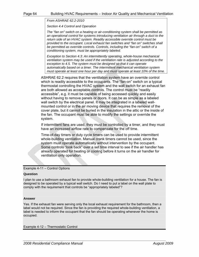
Page 64 Building HVAC Requirements – Indoor Air Quality and Mechanical Ventilation
2008 Residential Compliance Manual August 2009
From ASHRAE 62.2-2010
Section 4.4 Control and Operation
The “fan on” switch on a heating or air-conditioning system shall be permitted as an operational control for systems introducing ventilation air through a duct to the return side of an HVAC system. Readily accessible override control must be provided to the occupant. Local exhaust fan switches and “fan on” switches shall be permitted as override controls. Controls, including the “fan-on” switch of a conditioning system, must be appropriately labeled.
Exception to Section 4.3: An intermittently operating, whole-house mechanical ventilation system may be used if the ventilation rate is adjusted according to the exception to 4.5. The system must be designed so that it can operate automatically based on a timer. The intermittent mechanical ventilation system must operate at least one hour per day and must operate at least 10% of the time.
ASHRAE 62.2 requires that the ventilation system have an override control which is readily accessible to the occupants. The “fan-on” switch on a typical thermostat controlling the HVAC system and the wall switch for an exhaust fan are both allowed as acceptable controls. The control must be “readily accessible”, e.g. it must be capable of being accessed quickly and easily without having to remove panels or doors. It can be as simple as a labeled wall switch by the electrical panel. It may be integrated in a labeled wall-mounted control or in the air moving device that requires the removal of the cover plate, but it cannot be buried in the insulation in the attic or the inside of the fan. The occupant must be able to modify the settings or override the system.
If intermittent fans are used, they must be controlled by a timer, and they must have an increased airflow rate to compensate for the off time.
Time-of-day timers or duty cycle timers can be used to provide intermittent whole-building ventilation. Manual crank timers cannot be used, since the system must operate automatically without intervention by the occupant. Some controls “look back” over a set time interval to see if the air handler has already operated for heating or cooling before it turns on the air handler for ventilation only operation.
Example 4-11 – Control Options
Question
I plan to use a bathroom exhaust fan to provide whole-building ventilation for a house. The fan is designed to be operated by a typical wall switch. Do I need to put a label on the wall plate to comply with the requirement that controls be “appropriately labeled”?
Answer
Yes. If the exhaust fan were serving only the local exhaust requirement for the bathroom, then a label would not be required. Since the fan is providing the required whole-building ventilation, a label is needed to inform the occupant that the fan should be operating whenever the home is occupied.
Example 4-12 – Thermostatic Control

Building HVAC Requirements – Indoor Air Quality and Mechanical Ventilation Page 65
2008 Residential Compliance Manual August 2009
Question
I plan to provide ventilation air by connecting a duct run from the return side of the central air handler to the outdoors. Ventilation will be provided whenever the air handler operates. According to my estimates, the system will run on calls for heating and cooling about 40 percent of the time, averaged over the year. If I provide a safety factor and assume that it only runs 25 percent of the time, and size the airflow accordingly, can I allow the system to run under thermostatic control?
Answer
No. A system under thermostatic control will go through periods with little or no operation when the outdoor temperature is near the indoor setpoint, or if the system is in setback mode. An intermittently operating ventilation system MUST be controlled by a timer in order to assure that adequate ventilation is provided regardless of outdoor conditions.
As mentioned in the text, there are timer based controls available that function to keep track of when (and for how long) the system operates to satisfy heating/cooling requirements in the home. These controls only turn on the central fan to provide additional ventilation air when heating/cooling operation of the central fan has not already operated enough to provide the required ventilation.
4.6.3 Whole-Building Mechanical Ventilation Energy Consumption For builders using the performance compliance approach the energy use of fans (other than CFI fans) installed to meet the whole-building ventilation requirement is usually not an issue because the standard design W/CFM is set equal to the proposed design W/CFM up to an energy use level sufficient to accommodate most well designed ventilation systems. Also, the standard design whole-building ventilation system airflow rate is set equal to the proposed design whole-building ventilation system airflow rate so there is no energy penalty or credit for most systems. Systems that utilize Heat Recovery or Energy Recovery ventilators (HR/ERV) may need to account for the heat recovery benefit in the performance calculation to make up for their high energy use.
The energy use of the central air handler fan utilized for a CFI ventilation system must conform to the same fan Watt draw (W/CFM) limit as is the prescriptive requirement for cooling systems in climate zones 10-15. CFI systems are the only type of ventilation system that must meet a prescriptive fan Watt draw requirement that must be tested by the builder/installer, and verified by a HERS rater in accordance with the diagnostic test protocols given in RA3.3.
Energy use of fans installed for other purposes such as local exhaust is not regulated in the Standards.
A. Central Fan Integrated Ventilation Systems - Watt Draw §150.1(f)10. Central Fan Integrated Ventilation Systems. Central forced air system fans used in central fan integrated ventilation systems shall demonstrate, in Air Distribution Mode, an air-handling unit fan efficiency less than or equal to 0.58 W/CFM as confirmed through field verification and diagnostic testing in accordance with all applicable procedures specified in Reference Appendix RA 3.3.
CFI system automatic controls must operate the central system air handler fan (generally part of every hour of the year) in order to draw in and/or distribute ventilation air around the home even when there is no heating or cooling required. CFI systems generally do not operate continuously, thus do not meet

Page 66 Building HVAC Requirements – Indoor Air Quality and Mechanical Ventilation
2008 Residential Compliance Manual August 2009
the whole-building ventilation requirement as a “continuous" system. Because the CFI ventilation control increases the central system air handler fan run time significantly, and because typical central system air handler fan and duct systems require a large amount of power, a CFI ventilation system can use a very significant amount of electricity on an annual basis.
The 2008 update includes prescriptive standards for central system air handler fan Watt draw for cooling systems in the hottest California climates. The same prescriptive fan Watt draw requirement also applies to any central system air handler used for a CFI system installed in any California climate zone. Compliance with this requirement involves a post-construction measurement by the installing contractor of the airflow through the air handler cooling coil, and the simultaneous measurement of the Watt draw of the air handler fan motor. This fan Watt draw measurement must be verified by a HERS rater (see Reference Residential Appendix RA3.3). The central system air handler must be operating in ventilation mode (outdoor air damper is open and ventilation air is flowing into the return plenum from outside the building) and the airflow that must be measured is the total airflow through the air handler (cooling coil airflow), which is the sum of the return airflow, and the outside air ducted to the return plenum (ventilation airflow). To pass the test, the watt draw must be less than 0.58 W/CFM.
Builders who utilize CFI systems and comply using the performance approach have the option of accepting the default value for the central system fan Watt draw of 0.8 W/CFM (which does not require a post-construction measurement and HERS verification). Alternatively, the builder can specify a lower W/CFM value for compliance which must be tested and verified by a HERS rater. In either case the compliance software will check the furnace fan heating and cooling operation every hour, and if the air handler has not been operating for at least 20 minutes during that hour, the software will calculate energy use for operation in CFI mode until 20 minutes of fan operating occurs. The standard design ventilation energy consumption for that hour will be calculated as the extra fan run time at a Watt draw of 0.58 W/CFM. The proposed design ventilation energy for that hour will be calculated as the extra fan run time at the Watt draw that was specified for compliance, otherwise at the default Watt draw of 0.8 W/CFM.
B. Other Whole-Building Ventilation Systems – Watt Draw
There are no prescriptive requirements for maximum fan energy (Watt draw) for whole-building ventilation systems other than CFI systems.
Builders who specify other whole-building ventilation systems and comply using the performance approach have the option of accepting the default minimum whole-building ventilation airflow rate and a Watt draw value of 0.25 W/CFM which is typical of simple exhaust fans that meet the 1 Sone requirement. If the builder installs a whole-building ventilation system that has a fan Watt draw specification greater than 1.2 W/CFM of ventilation airflow, then he must input the ventilation airflow (CFM) and Watt draw (W/CFM) corresponding to the system that he proposes to install. The compliance software will simulate whole-building ventilation using the builder’s specified ventilation CFM and W/CFM for the proposed design. For the standard design the builders proposed CFM and 1.2 W/CFM will be used. If the builder specifies a system with heat recovery he inputs the recovery efficiency of his
Building HVAC Requirements – Indoor Air Quality and Mechanical Ventilation Page 67
2008 Residential Compliance Manual August 2009
proposed system and the compliance software uses it in the proposed design to calculate the heating and cooling impact of the whole-building ventilation. Ventilation heat recovery is never used in the standard design.
4.6.4 Local Exhaust (Section 5 of ASHRAE 62.2) Local exhaust (sometimes called spot ventilation) has long been required for bathrooms and kitchens to deal with moisture and odors at the source. Building codes have required an operable window or an exhaust fan in baths for many years and have generally required kitchen exhaust either directly through a fan or indirectly through a ventless range hood and an operable window. The 2008 Standards recognize the limitations of these indirect methods of providing ventilation to reduce moisture and odors and requires that these spaces be mechanically exhausted directly to outdoors even if windows are present. As we build tighter homes with more insulation, the relative humidity in the home has increased and the potential for condensation on cool or cold surfaces has increased as well. The presence of moisture condensation has been a leading cause of mold and mildew in both new and existing construction. The occurrence of asthma has also increased as the interior relative humidity has gotten higher. Therefore, it has become more important to remove the moisture from bathing and cooking right at the source.
The Standards require that each kitchen and bathroom have a local exhaust system installed. Generally this will be accomplished by installing a dedicated exhaust fan in each room that requires local exhaust, although ventilation systems that exhaust air from multiple rooms utilizing a duct system connected to a single ventilation fan are allowed as long as the minimum local ventilation airflow rate requirement is met in all rooms served by the system. The Standards define kitchens as any room containing cooking appliances, and bathrooms are rooms containing a bathtub, shower, spa, or other similar source of moisture. Note that a room containing only a toilet is not required by the Standards to have mechanical exhaust; it assumes that there will be an adjacent bathroom which will have local exhaust.
The Standards allow the designer to choose between intermittent operation or continuous operation for the local exhaust ventilation system. The ventilation rates are different because the ventilation effectiveness of an intermittent operation fan is different than the ventilation effectiveness of a continuous operation fan.
Building codes may require that fans used for kitchen range hood ventilation be safety-rated by UL or some other testing agency for the particular location and/or application. Typically, these requirements address the fire safety issues of fans placed within an area defined by a set of lines at 45° outward and upward from the cook top. Few “bath” fans will have this rating and cannot be used in this area of the kitchen ceiling.
Example 4-13 – Local Exhaust Required for Toilet
Question
I am building a house with 2½ baths. The half bath consists of a room with a toilet and sink. Is local exhaust required for the half bath?

Page 68 Building HVAC Requirements – Indoor Air Quality and Mechanical Ventilation
2008 Residential Compliance Manual August 2009
Answer
No. Local exhaust is required only for bathrooms, which are defined by the Standards as rooms with a bathtub, shower, spa or some other similar source of moisture. This does not include a simple sink for occasional hand washing.
Example 4-14
Question
The master bath suite in a house has a bathroom with a shower, spa and sinks. The toilet is in a separate, adjacent room with a full door. Where do I need to install local exhaust fans?
Answer
The Standards only requires local exhaust in the bathroom, not the separate toilet room.
A. Intermittent Local Exhaust
The Standards requires that intermittent local exhaust fans be designed to be operated by the occupant. This usually means that a wall switch or some other type of control is accessible and obvious. There is no requirement to specify where the control or switch needs to be located, but bath fan controls are generally located next to the light switch, and range hood or downdraft fan controls are generally integrated into the range hood or mounted on the wall or counter adjacent to the range hood.
Bathrooms can use a variety of exhaust strategies. They can utilize typical ceiling bath fans or may utilize one or two pickups for remote inline or exterior-mounted fans or heat recovery products. Intermittent local exhaust can be integrated with the whole-building ventilation system to provide both functions. Kitchens can have range hoods, down-draft exhausts, ceiling fans, wall fans, or pickups for remote inline or exterior-mounted fans. Generally, HVR/ERV manufacturers will not allow kitchen pickups to avoid the issue of grease buildup in the heat exchange core. Building codes typically require that the kitchen exhaust must be exhausted through metal ductwork for fire safety.
Example 4-15 – Ducting Kitchen Exhaust to the Outdoors
Question
How do I know what kind of duct I need to use. I’ve been using recirculating hoods my entire career, now I need to vent to outdoors. How do I do it?
Answer
Kitchen range hood or downdraft duct is generally smooth metal duct that is sized to match the outlet of the ventilation device. It is often six inch or seven inch round duct or the range hood may have a rectangular discharge. If it is rectangular, the fan will typically have a rectangular-to-round adapter included. Always use a terminal device on the roof or wall that is sized to be at least as large as the duct. Try to minimize the number of elbows used.
Example 4-16
Question

Building HVAC Requirements – Indoor Air Quality and Mechanical Ventilation Page 69
2008 Residential Compliance Manual August 2009
How do I know what the requirements are in my area?
Answer
Ask your enforcement agency for that information. Some enforcement agencies will accept metal flex, some will not.
B. Control and Operation for Intermittent Local Exhaust
The choice of control is left to the designer. It can be an automatic control like an occupancy sensor or a manual switch. Some products have multiple speeds and some switches have a delay-off function that continues the exhaust fan flow for a set time after the occupant leaves the bathroom. New control strategies continue to come to the market. The only requirement is that there is a control.
C. Ventilation Rate for Intermittent Local Exhaust
A minimum intermittent ventilation airflow of 100 cfm is required for the kitchen range hood and a minimum intermittent ventilation airflow of 50 cfm is required for the bath fan.
The 100 cfm requirement for the range hood or microwave/hood combination is the minimum to adequately capture the moisture and other products of cooking and/or combustion. The kitchen exhaust requirement can also be met with either a ceiling or wall-mounted exhaust fan or with a ducted fan or ducted ventilation system that provides at least 5 air changes of the kitchen volume per hour. Recirculating range hoods that do not exhaust pollutants to the outside cannot be used to meet the requirements of the ASHRAE Standard 62.2.
Most range hoods provide more than one speed, with the high speed at 150 cfm or more – sometimes much more. Range hoods are available that are rated for 1,000 or 1,500 cfm on high speed and are often specified when large commercial-style stoves are installed. Care must be taken to avoid backdrafting combustion appliances when large range hoods are used.Refer to Table 5.1 in ASHRAE 62.2 for intermittent local ventilation exhaust airflow rates.
Example 4-17 – Is an Intermittent Range Hood Required?
Question
I am building a house with a kitchen that is 12 ft x 14 ft with a 10 ft ceiling. What size ceiling exhaust fan is required?
Answer
The kitchen volume is 12 ft x 14 ft x 10 ft = 1680 ft3. 5 air changes is a flowrate of 1680 ft³ x 5/ hr ÷ 60 min/hr = 140 cfm. So this kitchen must have a ceiling or wall exhaust fan of 140 cfm or a 100 cfm vented range hood.
D. Continuous Local Exhaust
The Standards allow the designer to install a local exhaust system that operates without occupant intervention continuously and automatically during all occupiable hours. Continuous local exhaust is generally specified when the

Page 70 Building HVAC Requirements – Indoor Air Quality and Mechanical Ventilation
2008 Residential Compliance Manual August 2009
local exhaust ventilation system is combined with a continuous whole-building ventilation system. For example, if the whole-building exhaust is provided by a continuously operating exhaust fan located in the bathroom, this fan satisfies the local exhaust requirement for the bathroom. The continuous local exhaust may also be part of the continuous whole-building ventilation system, such as a pickup for a remote fan or HRV/ERV system.
Continuously operating bathroom fans must operate at a minimum of 20 cfm and continuously operating kitchen fans must operate at 5 air changes per hour. Note: these continuous ventilation airflow rates are different than the ventilation airflow rates required for intermittent local exhaust. Refer to Table 5.2 in ASHRAE 62.2 for continuous local ventilation exhaust airflow rates.
The requirement that continuous kitchen exhaust fans must provide 5 air changes per hour is due to the difficulty of a central exhaust to adequately remove contaminants released during cooking from kitchens that may be quite large, have an open-plan design, or have high ceilings. The only way to avoid a vented kitchen hood is to provide more than 5 air changes per hour of constant local exhaust ventilation.
Example 4-18 – Continuous Kitchen Exhaust
Question
The kitchen in an apartment is 5 ft. by 10 ft., with an 8 ft ceiling. If a continuous ceiling-mounted exhaust fan is used, what must the airflow be?
Answer
The kitchen volume is 5 ft x 10 ft x 8 ft = 400 ft3. 5 air changes equates to 400 ft³ x 5/hr ÷ 60 min/hr = 34 cfm.
Example 4-19
Question
A new house has an open-design 12 ftx18 ft ranch kitchen with 12 ft cathedral ceilings. What airflow rate will be required for a continuous exhaust fan?
Answer:
The kitchen volume is 12 ft x 18 ft x 12 ft = 2592 ft³. The airflow required is 2592 ft³ x 5/hr ÷ 60 min/hr = 216 cfm.
4.6.5 Other Requirements (Section 6 of ASHRAE 62.2)
A. Transfer Air From ASHRAE 62.2-2010
6.1 Adjacent Spaces
Measures shall be taken to minimize air movement across envelope components to occupiable spaces from garages, unconditioned crawl spaces, and unconditioned attics. Supply and balanced ventilation systems shall be designed and constructed to provide ventilation air directly from the outdoors.
ASHRAE Standard 62.2 requires that the air used for ventilation purposes come from the outdoors. Air may not be drawn in as transfer air from other spaces that are outside the occupiable space of the dwelling unit. This is to prevent airborne pollutants originating in those other spaces from

Building HVAC Requirements – Indoor Air Quality and Mechanical Ventilation Page 71
2008 Residential Compliance Manual August 2009
contaminating the dwelling unit. For example, drawing ventilation air from the garage could introduce VOCs, or pesticides into the indoor air. Drawing ventilation air from an unconditioned crawlspace could cause elevated allergen concentrations in the dwelling such as mold spores, insects or rodent allergens. Likewise, drawing air from an adjacent dwelling could introduce unwanted contaminants such as cooking products or cigarette smoke.
In addition to designing the ventilation system to draw air from the outdoors, the standard also requires that measures be taken to prevent air movement between adjacent dwelling units and between the dwelling unit and other adjacent spaces, such as garages. The measures can include air sealing of envelope components, pressure management and use of airtight recessed light fixtures. The measures must apply to adjacent units both above and below, as well as side by side.
Air sealing must include pathways in vertical components such as party walls and walls common to the unit and an attached garage; and in horizontal components such as floors and ceilings. Pipe and electrical penetrations are examples of pathways that require sealing.
Section 6.1 of ASHRAE 62.2 does not prohibit whole-building exhaust or local exhaust ventilation systems, and does not require mechanical systems to maintain pressure relationships with adjacent spaces except as required by Section 6.4 of ASHRAE 62.2.
B. Instructions and Labeling From ASHRAE 62.2-2010
6.2 Instructions and Labeling
Information on the ventilation design and/or ventilation systems installed, instructions on their proper operation to meet the requirements of this standard, and instructions detailing any required maintenance (similar to that provided for HVAC systems) shall be provided to the owner and the occupant of the dwelling unit. Controls shall be labeled as to their function (unless that function is obvious, such as toilet exhaust fan switches). See Chapter 13 of Guideline 242 for information on instructions and labeling.
There has been a history of ventilation systems that worked initially but failed due to lack of information for the occupant or lack of maintenance. So ASHRAE Standard 62.2 requires that the installer or builder provide written information on the basic ventilation concept being used and the expected performance of the system. These instructions must include how to operate the system and what maintenance is required.
Because the concept of a designed whole-building ventilation system may be new to a lot of occupants, the standard requires that ventilation system controls be labeled as to their function. No specific wording is mandated, but the wording needs to make clear what the control is for and the importance of operating the system. This may be as simple as “Ventilation Control” or might include wording such as “Operate whenever the house is in use” or “Keep on except when gone over 7 days”. If the system is designed to operate with a timer as an intermittent system, the labeling may need to be more complex. One acceptable option is to affix a label to the electrical panel that provides some basic system operation information.
C. Clothes Dryers

Page 72 Building HVAC Requirements – Indoor Air Quality and Mechanical Ventilation
2008 Residential Compliance Manual August 2009
From ASHRAE 62.2-2010
6.3 Clothes Dryers
Clothes dryers shall be exhausted directly to the outdoors.
Exception: Condensing dryers plumbed to a drain.
All laundry rooms must be built with a duct to the outdoors, designed to be connected to the dryer. Devices which allow the exhaust air to be diverted into the indoor space to provide extra heating are not permitted. This requirement is consistent with existing clothes dryer installation and design standards.
In multi-family buildings, multiple dryer exhaust ducts can be connected to a common exhaust only when dampers are provided to prevent recirculation of exhaust air from one apartment to another.
Example 4-20 – Clothes Dryer Exhaust Diverter
Question
I am building a home which has been purchased prior to completion. The buyer has asked for an exhaust air diverter to be installed in the dryer exhaust duct. He says that it is wasteful of heating energy to exhaust the warm humid air to the outdoors during the winter when the furnace and humidifier are working. He says that the screen on the diverter will prevent excess dust being released into the space. Can I install the device for him?
Answer
If you do, you will not comply with the Standards. The device is specifically prohibited. Significant amounts of dust are released from such devices, and the moisture in the dryer exhaust can lead to humidity problems as well, particularly in warmer climates.
D. Combustion and Solid-Fuel Burning Appliances From ASHRAE 62.2-2010
6.4 Combustion and Solid-Fuel Burning Appliances
Combustion and solid-fuel burning appliances must be provided with adequate combustion and ventilation air and vented in accordance with manufacturer’s installation instructions, NFPA 54/ANSI Z223.1, National Fuel Gas Code, NFPA 31, Standard for the Installation of Oil-Burning Equipment, or NFPA 211, Standard for Chimneys, Fireplaces, Vents, and Solid-Fuel Burning Appliances, or other equivalent code acceptable to the building official.
Where atmospherically vented combustion appliances or solid-fuel burning appliances are located inside the pressure boundary, the total net exhaust flow of the two largest exhaust fans (not including a summer cooling fan intended to be operated only when windows or other air inlets are open) shall not exceed 15 cfm/100 ft² (75 Lps/100 m2) of occupiable space when in operation at full capacity. If the designed total net flow exceeds this limit, the net exhaust flow must be reduced by reducing the exhaust flow or providing compensating outdoor airflow. Atmospherically vented combustion appliances do not include direct-vent appliances.
ASHRAE Standard 62.2 requires that the vent system for combustion appliances be properly installed, as specified by the instructions from the appliance manufacturer and by the California Building Code. Compliance with the venting requirements will involve determining the type of vent material to be used, the sizing of the vent system, and vent routing requirements.
ASHRAE Standard 62.2 includes a provision intended to prevent backdrafting where one or more large exhaust fans are installed in a home with atmospherically vented or solid fuel appliances. If the two largest exhaust fans have a combined capacity that exceeds 15 cfm/100 ft² of floor area, then an

Building HVAC Requirements – Indoor Air Quality and Mechanical Ventilation Page 73
2008 Residential Compliance Manual August 2009
electrically interlocked makeup air fan must be installed so that the net exhaust is less than 15 cfm/100 ft² with either or both fans operating. This provision applies only when the atmospherically vented appliance is inside the pressure boundary of the house, and does not include a summer cooling fan which is designed to be operated with the windows open. Direct-vent appliances are not considered “atmospherically vented.”
The 2 largest exhaust fans are normally the kitchen range hood and the clothes dryer (if located inside the dwelling unit pressure boundary). Many large range hoods, particularly down draft range hoods, have capacities of 1,000 cfm or more.
A problem with this requirement can be solved in one of three ways. First, all atmospherically vented combustion appliances can be moved outside the pressure boundary of the house (to the garage or other similar space). Second, the flowrate of one or more of the fans can be reduced so that the combined flow is less than 15 cfm/100 ft². Finally, a supply fan can be installed to balance the flow.
Example 4-21 – Large Exhaust Fan
Question
I am building a 3,600 ft2custom home that has 4 bedrooms. The kitchen will have a high end range hood that has three speeds, nominally 1000 cfm, 1400 cfm and 1600 cfm. The house will be heated with a gas furnace located in the basement. If I am using a central exhaust fan for the whole-building ventilation of 90 cfm, and there is a clothes dryer installed, how large does my compensating supply fan need to be?
Answer
You must use the high speed value for the range hood of 1600 cfm. The clothes dryer will have a flow that is assumed to be 150 cfm for sizing purposes. These two flows must be added together for a total exhaust capacity of 1750 cfm. Since the whole-building ventilation fan is not one of the two largest exhaust fans, it does not figure into sizing the supply fan. Using the equation above, the supply fan must be at least 1750 cfm – 15 cfm x 3600 ft² / 100 ft² = 1210 cfm.
Example 4-22
Question
The same custom house will have the furnace located in the garage instead of the basement. Does that change anything?
Answer
The garage and the attic would both normally be considered outside the pressure boundary, so no compensating fan would be required. An exception to this would be if the attic is specially designed to be inside the pressure boundary, then the answer would be the same as for Example 4-23.
Example 4-23
Question
For this house, I need to keep the furnace in the basement. What are my options that would avoid using the compensating supply fan?

Page 74 Building HVAC Requirements – Indoor Air Quality and Mechanical Ventilation
2008 Residential Compliance Manual August 2009
Answer
There are several things you could do. First, you could use direct vent appliances which would give higher efficiency and would not require a supply fan. You could use a lower capacity range hood,one that is less than 390 cfm (15 cfm x 3600 ft² / 100 ft² – 150 cfm).Use of supply-only
whole-building ventilation would allow the hood capacity to increase to 480 cfm (15 cfm x 3600 ft² / 100 ft² – 150 cfm + 90 cfm). There are also range hoods available in the commercial market that have integrated supply fans (or makeup air).One of these units would be acceptable too.
E. Garages From ASHRAE 62.2-2010
6.5.1 Garages
When an occupiable space adjoins a garage, the design must prevent migration of contaminants to the adjoining occupiable space. Air seal the walls, ceilings, and floors that separate garages from occupiable space. To be considered air sealed, all joints, seams, penetrations, openings between door assemblies and their respective jambs and framing, and other sources of air leakage through wall and ceiling assemblies separating the garage from the residence and its attic area shall be caulked, gasketed, weather stripped, wrapped, or otherwise sealed to limit air movement. Doors between garages and occupiable spaces shall be gasketed or made substantially airtight with weather stripping.
Garages often contain numerous sources of contaminants. These include gasoline and exhaust from vehicles, pesticides, paints and solvents, etc. The Standards require that when garages are attached to the house, these contaminants be prevented from entering the house. The wall between the unit and garage (or garage ceiling in designs with living space above garages) shall be designed and constructed so that no air migrates through the wall or ceiling. The common doors and any air handlers or ducts located in the garage shall also be sealed, weather-stripped or gasketed. Use of an exterior door system would address this requirement.
If an air handling unit (furnace) is located in the garage, or return ducts are located in the garage (regardless of the air handler location) the entire duct system must meet the sealed and tested ducts criteria.
Example 4-24 – Garages
Question
The building designer located the air handler in the garage. The main return trunk from the dwelling is connected to the air handler. Is this acceptable?
Answer
Yes, provided that the duct system is leak tested at 25 Pa. and sealed, if necessary, to have leakage no greater than 6 percent of the total fan flow.
Example 4-25
Question
The building designer located the air handler in the dwelling unit. A return duct runs through the garage to a bedroom above the garage. The duct has only 4 ft of length in the garage. How do I test that length of the duct?
Answer

Building HVAC Requirements – Indoor Air Quality and Mechanical Ventilation Page 75
2008 Residential Compliance Manual August 2009
This design is allowed but the entire duct system must be leak tested at 25 Pa. and sealed, if necessary, to have leakage no greater than 6 percent of the total fan flow. There is no test available to leak test only the garage portion of the duct system.
F. Ventilation Opening Area From ASHRAE 62.2-2010
6.6 Ventilation Opening Area
Spaces shall have ventilation openings as listed below. Such openings shall meet the requirements of Section 6.8.
Exception: Spaces that meet the local ventilation requirements set for bathrooms in Section 5.
6.6.1 Habitable Spaces
Each habitable space shall be provided with ventilation openings with an openable area not less than 4% of the floor area, nor less than 5 ft² (0.5 m2).
6.6.2 Toilets and Utility Rooms
Toilets and utility rooms shall be provided with ventilation openings with an openable area not less than 4% of the room floor area, nor less than 1.5 ft² (0.15 m2).
Exceptions: (1) Utility rooms with a dryer exhaust duct; (2) toilet compartments in bathrooms.
The whole-building mechanical ventilation is intended to provide adequate ventilation to typical new homes under normal circumstances. On occasion, however, houses experience unusual circumstances where high levels of contaminants are released into the space. When this occurs, some means of providing the significantly higher levels of ventilation required to remove the contaminants is needed. Operable windows are the most likely means of providing the additional ventilation.
This section of ASHRAE Standard 62.2 requires ventilation openings in habitable spaces, toilets and utility rooms. Ventilation openings usually means operable windows, although a dedicated non-window opening for ventilation is acceptable. Spaces that meet the local exhaust requirements are exempted from this requirement.
G. Habitable Spaces
Habitable spaces are required to have ventilation openings with openable area equal to at least 4 percent of the space floor area (but not less than 5 ft2). Rooms people occupy are considered habitable space. Dining rooms, living rooms, family rooms, bedrooms and kitchens are considered habitable space. Closets, crawl spaces, garages and utility rooms are generally not. If the washer and dryer are located in an open basement that is also the family room, it would be considered habitable space.
The openings do not have to be provided by windows. They can also be provided by operable, insulated, weather-stripped panels.
Ventilation openings, which include windows, skylights, through-the-wall inlets, window air inlets, or similar devices, shall be readily accessible to the occupant. This means that the occupant must be able to operate the opening without having to climb on anything. An operable skylight must have some means of being operated while standing on the floor: a push rod, a long crank handle, or an electric motor.
If a ventilation opening is covered with louvers or otherwise obstructed, the openable area is the unobstructed free area through the opening.

Page 76 Building HVAC Requirements – Indoor Air Quality and Mechanical Ventilation
2008 Residential Compliance Manual August 2009
Example 4-26 – Ventilation Openings
Question
I am building a house with a 14 ft. by 12 ft. bedroom. What size window do I need to install?
Answer
It depends on the type of window. The standard requires that the openable area of the window, not the window unit, be 4 percent of the floor area, or 14 ft x 12 ft’ x 0.04 = 6.7 ft². The fully opened area of the window or windows must be greater than 6.7 ft2. The requirement for this example can be met using two double hung windows each with a fully opened area of 3.35 ft2. Any combination of windows whose opened areas add up to at least 6.7 ft2 will meet the requirement.
Example 4-27 – Ventilation Opening Louvers
Question
There are fixed wooden louvers over a window in a bedroom. The louvers have slats that are 1/8 in thick, and they are spaced 1 inch apart. What is the reduction in openable area?
Answer
Assuming that the 1 inch spacing was measured perpendicular to the slats (the correct way), then the reduction is the slat thickness divided by the spacing, or 1/8 inch. So the credited opening area is the original opening area x (1 inch – 1/8 inch)/1 inch = 7/8 inch of the original opening area.
H. Minimum Filtration From ASHRAE 62.2-2010
6.7 Minimum Filtration
Mechanical systems that supply air to an occupiable space through ductwork exceeding 10 ft (3 m) in length and through a thermal conditioning component, except evaporative coolers, shall be provided with a filter having a designated minimum efficiency of MERV 6, or better, when tested in accordance with ANSI/ASHRAE Standard 52.2, Method of Testing General Ventilation Air-Cleaning Devices for Removal Efficiency by Particle Size, or a minimum Particle Size Efficiency of 50% in the 3.0-10 µm range in accordance with AHRI Standard 680, Performance Rating of Residential Air Filter Equipment. The system shall be designed such that all recirculated and mechanically supplied outdoor air is filtered before passing through the thermal conditioning components. The filter shall be located and installed in such a manner as to facilitate access and regular service by the owner.
ASHRAEStandard62.2 requires that particulate air filtration of no less than MERV 6 efficiency is installed in any HVAC system having more than 10 ft of ductwork. The particulate filter must be installed such that all of the air circulated through the furnace or air handler is filtered prior to passing through the thermal conditioning portion of the system. In addition, the standard requires that the filter be located and installed for easy access and service by the homeowner. Lastly, the standard requires that the filter cartridge be sized to operate at no greater than 0.1 inch water column when clean, or that the air handler be selected to handle greater pressure loss without undue restriction on airflow.
Many residential units have factory installed filter cartridges that comply with this minimum filtration requirement. These are normally 1-inch thick with a pleated media configuration to attain the proper efficiency and airflow performance. If the filter bank is to be field installed, the sizing selection is critical to HVAC system performance.
The filter retainer section must be easily accessible by the homeowner to

Building HVAC Requirements – Indoor Air Quality and Mechanical Ventilation Page 77
2008 Residential Compliance Manual August 2009
assure continued monitoring and replacement. The filter bank may be located in the air handler/furnace (1); in the return air plenum near the air handler (2a); in the return air plenum with a deep pleat cartridge (2b); angled across the return air plenum to enhance cross-section (3); or situated in a wall return grille (4). See Figure 4-16.
Figure 4-16 – Filter Location Options
The MERV 6 pleated filter provides enhanced particulate arrestance, but also provides longer service life than the conventional low efficiency panel filter. Typically, the pleated type filter will last 3 months or longer, depending upon operating conditions, as compared to the typical 1 month life cycle of disposable fiberglass filters. The deeper pleated versions will typically provide even longer life cycles, up to 1 year or more.
Example 4-28– Filter Sizing
Question
I am installing a 1200 cfm furnace in a new house. It has a 20 inches x 20 inches filter furnished and installed in the unit. Is this in compliance?
Answer
Yes, you may assume that the equipment manufacturer has selected a compliant filter efficiency and pressure drop to match the features of their air handler.
Example 4-29
Question
What if the above unit has no filter installed but recommends a 20 inches x 20 inches filter size? What filter do I select?
(1)(2a)(2b)(3)
(4)
Air Handler SA
RA

Page 78 Building HVAC Requirements – Indoor Air Quality and Mechanical Ventilation
2008 Residential Compliance Manual August 2009
Answer
A number of manufacturers produce a 1-inch deep MERV 6 for use in slide-in tracks and return air grills. If the pressure drop information is not furnished with the filter to assist with the selection, oversize the filter by at least one size multiple beyond the normal recommendation of the manufacturer. In this case, a filter selection of 20 inches” x 25 inches to over-size the filter would reduce the face velocity by 25 percent, which in turn reduces the initial pressure drop by almost 50 percent.
Example 4-30
Question
For the same 1200 cfm furnace, what other options do I have?
Answer
For any filter, the pressure drop, efficiency, and life cycle can all be affected by velocity control. By enlarging the filter cartridge size, the approach velocity is decreased along with the pressure drop. If the depth of the filter is increased, likewise the air velocity through the media is decreased, and that, in turn, substantially reduces the actual pressure drop. Doubling the pleat depth will halve the velocity through the media and decrease pressure drop by up to 75 percent.
Example 4-31
Question
I am installing an HVAC system with the filter to be installed at the return air grill. What should I do to accommodate a 1inch pleated MERV 6 filter?
Answer
You can reduce the face velocity and related pressure drop by employing multiple return air grilles. By doubling or tripling the return air filter surface area, the pressure drop is reduced by 75 percent or greater. Alternatively, you can increase the size of the return air grill similar to what was discussed in Example 4-31, above, or increase the depth of the filter as discussed in Example 4-32
Example 4-32
Question
I am installing a ductless split system in a space that is being added on to the house. Must I use the designated MERV 6 filter?
Answer
No, the requirement does not apply since there is no ductwork attached to the unit.
Example 4-33
Question
My builder supply house has only MERV 8 or greater efficiency filters. Is this in compliance?
Answer
Yes, this is a better efficiency. However, higher MERV filters usually have higher pressure drop. Make sure that the pressure drop does not exceed the MERV 6 specified performance level and adjust the size and related air velocity accordingly.

Building HVAC Requirements – Indoor Air Quality and Mechanical Ventilation Page 79
2008 Residential Compliance Manual August 2009
I. Air Inlets From ASHRAE 62.2-2010
Section 6.8 Air Inlets
Air inlets that are part of the ventilation design shall be located a minimum of 10 ft (3 m) from known sources of contamination such as a stack, vent, exhaust hood, or vehicle exhaust. The intake shall be placed so that entering air is not obstructed by snow, plantings, or other material. Forced air inlets shall be provided with rodent/insect screens (mesh not larger than 1/2 inch).
Exceptions:
a Ventilation openings in the wall may be as close as a stretched-string distance of 3 ft (1 m) from sources of contamination exiting through the roof or dryer exhausts.
b No minimum separation distance shall be required between windows and local exhaust outlets in kitchens and bathrooms.
c Vent terminations covered by and meeting the requirements of the National Fuel Gas Code (NFPA 54/ANSI Z223.1, National Fuel Gas Code) or equivalent.
When the ventilation system is designed with air inlets, the inlets must be located away from locations that can be expected to be sources of contamination. The minimum separation is 10 ft. Inlets include not only inlets to ducts, but windows which are needed to the opening area.
The Standards list some likely sources of contaminants. For typical residential applications, the sources will include:
• Vents from combustion appliances
• Chimneys
• Exhaust fan outlets
• Barbeque grills
• Locations where vehicles may be idling for any significant length of time
• Any other locations where contaminants will be generated
The Standards also require that air intakes be placed so that they will not become obstructed by snow, plants, or other material. Forced air inlets must also be equipped with insect/rodent screens, where the mesh is no larger than 1/2 inch.
There are three exceptions to the separation requirements.
1. Windows or ventilation openings in the wall can be as close as three feet to sources of contamination which exit through the roof or to dryer exhausts.
2. There is no minimum distance between windows and the outlet of a local exhaust outlet from kitchens or bathrooms.
3. Vent terminations which meet the requirements of the National Fuel Gas Code, which has its own separation and location requirements, do not need to meet the requirements.
Page 80 Building HVAC Requirements – Indoor Air Quality and Mechanical Ventilation
2008 Residential Compliance Manual August 2009
4.6.6 Air Moving Equipment (Section 7 of ASHRAE 62.2) From ASHRAE 62.2-2010
Section 7.1 Selection and Installation
Ventilation devices and equipment shall be tested in accordance with ANSI/ASHRAE Standard 51/AMCA 210, Laboratory Methods of Testing Fans for Aerodynamic Performance Rating, and ANSI/AMCA Standard 300, Reverberant Room Method for Sound Testing of Fans, and rated in accordance with the airflow and sound rating procedures of the Home Ventilating Institute (HVI 915, Procedure for Loudness Rating of Residential Fan Products, HVI 916, Air Flow Test Procedure, and HVI 920, Product Performance Certification Procedure Including Verification and Challenge). Installations of systems or equipment shall be carried out in accordance with manufacturers’ design requirements and installation instructions.
Equipment used to meet the whole-building ventilation requirements or the local ventilation exhaust requirements shall be rated to deliver the required airflow, and shall have sound ratings that meet the requirements of this section.
A. Selection and Installation
ASHRAE Standard 62.2 requires that equipment used to comply with the standard be selected based on tested and certified ratings of performance for airflow and sound. When selecting fans for use in meeting the requirements of the standard, you must check the Home Ventilating Institute (HVI) certified products directory to confirm that the equipment you select has been tested, and the rated performance meets the requirements. The HVI-Certified Products Directory can be viewed at the following link:
www.hvi.org/resourcelibrary/proddirectory.html
In addition, the Standard requires that the fans be installed in accordance with the manufacturer’s instructions. You must review the installation instructions and other literature shipped with the fan, and make sure that the installation complies with those instructions.
B. Sound Ratings for Fans From ASHRAE 62.2-2010
Section 7.2 Sound Ratings for Fans)
Ventilation fans shall be rated for sound at no less than the minimum airflow rate required by this standard, as noted below. These sound ratings shall be at minimum of 0.1 in. w.c. (25 Pa) static pressure in accordance with the HVI procedures referenced in Section 7.1.
Section 7.2.1 Whole-Building or Continuous Ventilation Fans.
These fans shall be rated for sound at a maximum of 1.0 sone.
Section 7.2.2 Intermittent Local exhaust Fans.
Fans used to comply with Section 5.2 shall be rated for sound at a maximum of 3 sone, unless their maximum rated airflow exceeds 400 cfm (200 L/s).
Exception: HVAC air handlers and remote-mounted fans need not meet sound requirements. To be considered for this exception, a remote-mounted fan must be mounted outside the habitable spaces, bathrooms, toilets, and hallways, and there must be at least 4 ft (1 m) of ductwork between the fan and the intake grille.
One common reason for not using ventilation equipment, particularly local exhaust fans, is the noise they create. To address this, ASHRAE Standard 62.2 requires that certain fans be rated for sound, and that installed fans shall have ratings below specified limits. The sound rating must be done at an airflow that is no less than the airflow that the fan must provide to meet the ventilation airflow requirement.

Building HVAC Requirements – Indoor Air Quality and Mechanical Ventilation Page 81
2008 Residential Compliance Manual August 2009
Because of the variables in length and type of duct and grille, there is no clearly repeatable way to specify a sound level for ventilation devices that are not mounted in the ceiling or wall surface. Consequently, air handlers, HRV/ERVs, inline fans and remote fans are exempted from the sound rating requirements that apply to surface-mounted fans. However, to reduce the amount of fan and/or motor noise that could come down the duct to the grille, the Standards sets a minimum of 4 ft of ductwork between the grille and the ventilation device. This may still produce an undesirable amount of noise for the occupant, especially if hard metal duct is used. Flexible insulated duct or a sound attenuator to will reduce the transmitted sound into the space.
Continuous Ventilation Fans (surface mounted fans) Continuously operated fans shall be rated at 1.0 sone or less. This 1.0 sone requirement applies to continuous whole-building ventilation fans, and also to continuous local ventilation exhaust fans.
Intermittent Fans (surface mounted fans) Intermittently operated whole-building ventilation fans shall be rated at a maximum of 1.0 sone.Intermittently operated local exhaust fans shall be rated at a maximum of 3.0 sone, unless the maximum rated airflow is greater than 400 cfm.
Thus, ASHRAE Standard 62.2 extends the requirement for quiet fans to include range hoods and regular bath fans, not just whole-building ventilation system fans. The whole-building fan or other combined systems that operate continuously to provide whole-building ventilation must be rated at 1.0 sone or less, but intermittent local ventilation exhaust fans, including intermittently operated bath fans, must be rated at a maximum of 3.0 sones. Range hoods must also be rated at 3.0 sones or less, but this is at their required “working speed” of 100 cfm. Most range hoods have maximum speeds of much more than 100 cfm, but 100 cfm is the minimum airflow that is required by the Standards.
C. Airflow Rating From ASHRAE 62.2-2010
Section 4.3 Airflow Measurement
The airflows required by this Section is the quantity of outdoor ventilation air supplied and/ or indoor air exhausted by the ventilation system as installed and shall be measured using a flow hood, flow grid, or other airflow measuring device. Ventilation airflow of systems with multiple operating modes shall be tested in all modes designed to meet this section.
Section 5.4 Airflow Measurement
The airflow required by this section is the quantity of indoor air exhausted by the ventilation system as installed and shall be measured using a flow hood, flow grid, or other airflow measuring device.
Exception to Section 5.4
The airflow rating, according to Section 7.1, at a pressure of 0.25 in. w.c. (62.5 Pa) may be used, provided th duct sizing meets prescriptive requirements of Table 5.3 or manufacturer’s design criteria.
Compliance with the ventilation airflow requirements for a ventilation system can be demonstrated in one of two ways:
1. The ventilation system can be tested using an airflow measuring device after completion of the installation to confirm that the delivered ventilation airflow meets the requirement. The builder/installer must also list the result of the airflow measurement(s) for the ventilation fan(s) on the Installation Certificate (CF-6R-MECH-05) for the building. The ventilation airflow must

Page 82 Building HVAC Requirements – Indoor Air Quality and Mechanical Ventilation
2008 Residential Compliance Manual August 2009
be measured and reported for any/all ventilation system types installed in the building, except for those described in item 2 below.
2. Simple exhaust systems can comply by performing and documenting an inspection of the installation to verify conformance to a prescriptive requirement that the fan has a certified airflow rating that meets or exceeds the required ventilation airflow, and the ducts for the ventilation system meet either the fan manufacturers published duct design specifications, or the prescriptive duct design requirements given in Table 4-12 below (Table 7.1 of ASHRAE 62.2). The builder/installer must also list the description of the installed fan equipment and duct design criteria for the ventilation fan(s) on the Installation Certificate (CF-6R-MECH-05) for the building.
The fan's certified airflow rating must be based on tested performance at the 0.25 inchw.c. operating point. The certified airflow rating of a ventilation device is generally available from the manufacturer, and is also available for hundreds of products in the Home Ventilating Institute (HVI) Certified Products Directory at the HVI website (www.hvi.org). Manufacturers can choose whether to provide the certified data for posting at the HVI website, but all of them should have available the rated data at 0.25 inches of water column static pressure.
If the manufacturer's duct system design specifications are utilized for compliance, the enforcement agency may require that the manufacturer's published system design documentation be provided for use in inspection of the installation(s).
The prescriptive duct design criteria given in Table 4-12 provide maximum duct lengths based on various duct diameters and duct type. As can be seen, the higher the flow, the larger in diameter or shorter in length the duct has to be. Also note that smooth duct can be used to manage longer duct runs. Interpolation and extrapolation of table 4-9 (Table 7.1 of ASHRAE 62.2) is not allowed. For airflow values not listed, use the next higher value. The table is not applicable for systems with airflow greater than 125 cfm at 0.25 inches of water column static pressure.
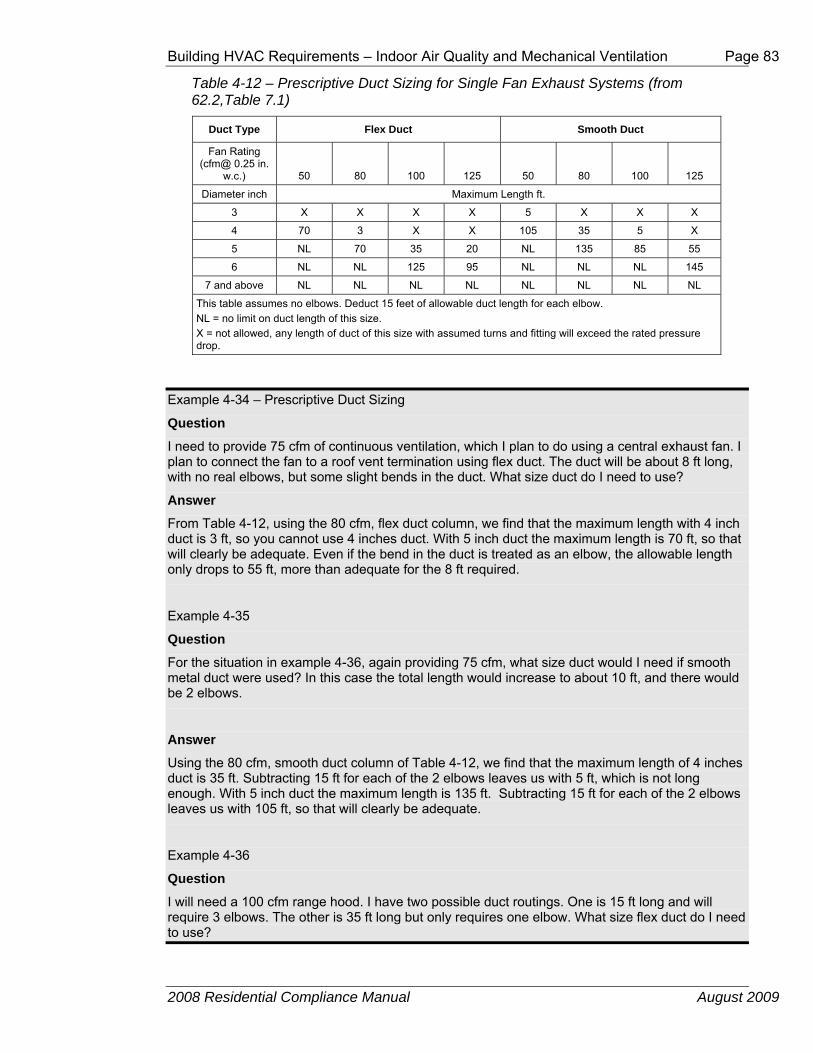
Building HVAC Requirements – Indoor Air Quality and Mechanical Ventilation Page 83
2008 Residential Compliance Manual August 2009
Table 4-12 – Prescriptive Duct Sizing for Single Fan Exhaust Systems (from 62.2,Table 7.1)
Duct Type Flex Duct Smooth Duct
Fan Rating (cfm@ 0.25 in.
w.c.) 50 80 100 125 50 80 100 125
Diameter inch Maximum Length ft.
3 X X X X 5 X X X
4 70 3 X X 105 35 5 X
5 NL 70 35 20 NL 135 85 55
6 NL NL 125 95 NL NL NL 145
7 and above NL NL NL NL NL NL NL NL
This table assumes no elbows. Deduct 15 feet of allowable duct length for each elbow. NL = no limit on duct length of this size. X = not allowed, any length of duct of this size with assumed turns and fitting will exceed the rated pressure drop.
Example 4-34 – Prescriptive Duct Sizing
Question
I need to provide 75 cfm of continuous ventilation, which I plan to do using a central exhaust fan. I plan to connect the fan to a roof vent termination using flex duct. The duct will be about 8 ft long, with no real elbows, but some slight bends in the duct. What size duct do I need to use?
Answer
From Table 4-12, using the 80 cfm, flex duct column, we find that the maximum length with 4 inch duct is 3 ft, so you cannot use 4 inches duct. With 5 inch duct the maximum length is 70 ft, so that will clearly be adequate. Even if the bend in the duct is treated as an elbow, the allowable length only drops to 55 ft, more than adequate for the 8 ft required.
Example 4-35
Question
For the situation in example 4-36, again providing 75 cfm, what size duct would I need if smooth metal duct were used? In this case the total length would increase to about 10 ft, and there would be 2 elbows.
Answer
Using the 80 cfm, smooth duct column of Table 4-12, we find that the maximum length of 4 inches duct is 35 ft. Subtracting 15 ft for each of the 2 elbows leaves us with 5 ft, which is not long enough. With 5 inch duct the maximum length is 135 ft. Subtracting 15 ft for each of the 2 elbows leaves us with 105 ft, so that will clearly be adequate.
Example 4-36
Question
I will need a 100 cfm range hood. I have two possible duct routings. One is 15 ft long and will require 3 elbows. The other is 35 ft long but only requires one elbow. What size flex duct do I need to use?

Page 84 Building HVAC Requirements – Alternative Systems
2008 Residential Compliance Manual August 2009
Answer
First, let’s take the 2 routings and add in the correction for the elbows. Elbow corrections can be either added to the desired length or subtracted from the allowable length. In this case, we know the desired length, so we’ll add the elbows. We get 15 ft plus 3 times 15 ft for a total of 60 ft, or 35 ft plus 15 ft equals 50 ft.
Looking at Table 4-12, in the 100 cfm, flex duct column, we find that the maximum length with 5 inches duct is 35 ft, which is less than the adjusted length for either routing. With 6 inches duct, the maximum length is 125 ft, longer than either adjusted length. 6 inch duct would need to be used for either routing. Note: The building code may not allow flex duct to be used for the range hood, in which case smooth duct would be required. For smooth duct, 5 inches would be acceptable.
D. Multi-Branch Exhaust Ducting From ASHRAE 62.2-2010
Section 7.3 Multi-Branch Exhaust Ducting (62.2 text)
If more than one of the exhaust fans in a dwelling unit shares a common exhaust duct, each fan shall be equipped with a back-draft damper to prevent the recirculation of exhaust air from one room to another through the exhaust ducting system. Exhaust fans in separate dwelling units shall not share a common exhaust duct.
ASHRAE Standard 62.2 contains restrictions on several situations where multiple exhausts are connected through a combined duct system. These restrictions are intended to prevent air from moving between spaces through the exhaust ducts.
The first restriction is that if more than one exhaust fan in a dwelling shares a common duct, then each fan must be equipped with a backdraft damper so that air exhausted from one bathroom or unit is not allowed to go into another space. Exhaust fans in multiple dwelling units may not share a common duct.
The other restriction applies to remote fans serving more than one dwelling unit. Sometimes a single remote fan or HRV/ERV will exhaust from several units in a multifamily building. This section does not preclude the use of that type of system, but it does require that either the shared exhaust fan operate continuously or that each unit be equipped with a backdraft damper so that air cannot flow from unit to unit when the fan is off.
In multifamily buildings, fire codes may impose additional restrictions.
4.7 Alternative Systems
4.7.1 Hydronic Heating Systems Hydronic heating is the use of hot water to distribute heat. Hydronic heating is discussed in this compliance manual as an “Alternative System” because it is much less common in California than in other parts of the United States.
A hydronic heating system consists of a heat source, which is either a boiler or water heater, and a distribution system. There are three main types of hydronic distribution systems, and they may be used individually or in combination:
Building HVAC Requirements – Alternative Systems Page 85
2008 Residential Compliance Manual August 2009
baseboard convectors or radiators, hot water air handlers, and radiant panel heating systems. These three options are illustrated in Figure 4-17.
Baseboard convectors or radiators are most effective when mounted near the floor. Cool air rises by gravity over heated panels or finned tubes and warms the air in the room. These devices also increase the mean radiant temperature of the space, improving comfort. Baseboard convectors or radiators do not require ducting.
Air handlers consist of a blower and finned tube coil enclosed in a sheet metal box (similar to a typical residential furnace), and may be ducted or non-ducted. Air handlers may also include refrigerant coils for air conditioning. Some air handlers are compact and can fit under cabinets.
Radiant panels may be mounted on or integrated with floors, walls, and ceilings. Radiant floor panels are most typical. See the separate section below for additional requirements specific to radiant floor designs.
A. Mandatory Requirements
For hydronic heating systems without ducts, the mandatory measures cover only pipe insulation, tank insulation, and boiler efficiency. Otherwise, for fan coils with ducted air distribution, the mandatory air distribution measures also apply as described earlier in this document. And for combined hydronic systems, as described below, mandatory water heating requirements also apply to the water heating portion of the system.
§150(j) Water System Pipe and Tank Insulation and Cooling Systems Line Insulation
The typical residential hydronic heating system operating at less than 200° F must have at least 1 inch (25 mm) of nominal R-4 insulation on pipes up to 2 inches (50 mm) in diameter and 1.5 inch (38 mm) of insulation on larger pipes. For other temperatures and pipe insulation characteristics see Tables 150-A and 150-B in the Standards.
There are a few exceptions where insulation is not required: sections of pipes where they penetrate framing members; pipes that provide the heat exchange surface for radiant floor heating; piping in the attic that is covered by at least 4 inches (100 mm) of blown insulation on top; and piping installed within walls if all the requirements for Insulation Installation Quality are met (see the envelope chapter).
If the system includes an unfired hot water storage tank, then the tank must be either wrapped with R-12 insulation or insulated internally to at least R-16.

Page 86 Building HVAC Requirements – Alternative Systems
2008 Residential Compliance Manual August 2009
Figure 4-17 – Hydronic Heating System Components
Figure 4-18 – Combined Hydronic System with Water Heater as Heat Source
§123 Requirements for Pipe Insulation
For pipes in hydronic heating systems that operate at pressure greater than 15 psi, the requirements of §123 apply. These are the same requirements that

Building HVAC Requirements – Alternative Systems Page 87
2008 Residential Compliance Manual August 2009
apply to nonresidential piping systems.
Appliance Efficiency Regulations, Title 20
Gas or oil boilers of the size typically used for residential space heating (less than 300,000 Btu/h capacity) must be rated with an AFUE of 80 percent or greater. A gas or oil water heater may also be used as a dedicated source for space heating. Other hot water sources, including heat pumps or electric resistance water heaters, are not allowed for use in dedicated space heating systems. Therefore, some water heaters may be used for space heating only if used as part of a combined hydronic system as described below. In that case, the mandatory water heater requirements apply.
Thermostat requirements also apply to hydronic systems as described in Section 4.5.1.
B. Prescriptive Requirements
There are no specific prescriptive requirements that apply to hydronic systems. However, if the system has a fan coil with ducted air distribution, the relevant prescriptive requirements apply, including duct insulation and duct sealing.
C. Compliance Options
Credit for choosing a hydronic heating system is possible using the performance compliance method. The standard design is assumed to have a furnace and ducted air distribution system. Therefore, hydronic systems without ducts can take credit for avoiding duct leakage penalties. In addition, minimizing the amount of pipe outside of conditioned space will provide some savings. Hydronic heating compliance calculations are described in the Residential ACM Manual, Chapter 5.
If the proposed hydronic system includes ducted air distribution, then the associated compliance options described earlier in this chapter may apply, such as adequate airflow (if there is air conditioning) and supply duct location.
A “combined hydronic” system is another compliance option that is possible when using the performance method. Combined hydronic heating refers to the use of a single water heating device as the heat source for both space and domestic hot water heating.
There are two types of combined hydronic systems. One uses a boiler as a heat source for the hydronic space heating system. The boiler also heats domestic water by circulating hot water through a heat exchanger in an indirect-fired water heater.

Page 88 Building HVAC Requirements – Alternative Systems
2008 Residential Compliance Manual August 2009
Figure 4-19 – Combined Hydronic System with Boiler and Indirect Fired Water Heater
The other type of hydronic heating uses a water heater as a heat source. The water heater provides domestic hot water as usual. Space heating is accomplished by circulating water from the water heater through the space heating delivery system. Sometimes a heat exchanger is used to isolate potable water from the water circulated through the delivery system. Some water heaters have built-in heat exchangers for this purpose.
For compliance calculations, the water heating function of a combined hydronic system is analyzed for its water heating performance as if the space heating function were separate. For the space heating function, an “effective” AFUE or HSPF rating is calculated. These calculations are performed automatically by the compliance software (see the compliance program vendor’s supplement).
4.7.2 Radiant Floor System One type of distribution system is the radiant floor system, either hydronic or electric, which must meet mandatory insulation measures (see below). Radiant floors may take one of several forms. Tubing or electric elements for radiant floor systems may be:
• Embedded in a concrete floor slab,
• Installed over the top of a wood sub-floor and covered with a concrete topping,
• Installed over the top of wood sub-floor in between wood furring strips, or
• Installed on the underside surface of wood sub-floor
In the latter two types of installations, aluminum fins are typically installed to spread the heat evenly over the floor surface, and to reduce the temperature of

Building HVAC Requirements – Alternative Systems Page 89
2008 Residential Compliance Manual August 2009
the water as required. All hydronic systems use one or more pumps to circulate hot water. Pumps are controlled directly or indirectly by thermostats, or by special outdoor reset controls.
A. Mandatory Insulation Measures §118(g) Insulation Requirements for Heated Slab Floors
Standards Table 118-A Slab Insulation Requirements for Heated Slab-On-Grade Floors
Table 4-13 – Slab Insulation Requirements for Heated Slabs
Location of Insulation
Orientation of Insulation Installation Criteria Climat
e ZoneInsulation R-value
Outside edge of heated slab, either inside or
outside the foundation wall
Vertical
From the level of the top of the slab, down 16 inches or to the frost line, whichever is greater? Insulation may
stop at the top of the footing where this is less than the required depth. For below-grade slabs, vertical insulation shall be extended from the top of the foundation wall to the bottom of the foundation (or the top of the footing) or
frost line, whichever is greater.
1-15
5
16 10
Between heated slab and outside
foundation wall
Vertical and Horizontal
Vertical insulation from the top of the slab at the inside edge of the outside wall down to the top of the horizontal insulation. Horizontal insulation from the outside edge of the vertical insulation extending 4 feet toward the center
of the slab in a direction normal to the outside of the building in the plan view.
1-15
5
16
10 vertical and
7 horizontal
Radiant floor systems in concrete slabs must have insulation between the heated portion of the slab and the outdoors.
When space heating hot water pipes or heating elements are set into a concrete slab-on-grade floor, slab-edge insulation from the level of the top of the slab, down 16 inches (200 mm) or to the frost line, whichever is greater (insulation may stop at the top of the footing, where this is less than the required depth), or insulation installed down from the top of the slab and wrapping under the slab for a minimum of 4 ft toward the middle of the slab, is required. The required insulation value for each of these insulating methods is either R-5 or R-10 depending on climate zone as shown in Table 4-. Any part of the slab extending outward horizontally must be insulated to the level specified in Table 4-.
When using the performance compliance method with slab-on-grade construction, the standard design includes slab edge insulation as described above using the F-factors in Reference Joint Appendix JA4, Table 4.4.8.
When space heating hot water pipes or heating elements are set into a lightweight concrete topping slab laid over a raised floor, insulation must be applied to the exterior of any slab surface from the top of the slab where it meets the exterior wall, to the distance below ground level described in Table 4-. If the slab does not meet the ground on its bottom surface, the specified insulation level must be installed on the entire bottom surface of the raised slab. Any part of the slab extending outward horizontally must be insulated to

Page 90 Building HVAC Requirements – Alternative Systems
2008 Residential Compliance Manual August 2009
the level specified in Table 4-. For lightweight slabs installed on raised floors and inside exterior walls, the overall wall R-value and overall floor R-value (determined as 1/(U-factor)) may be counted toward meeting the minimum R-value requirements specified in Table 4-.
Raised floor insulation that meets the mandatory minimum R-value for wood floor assemblies also meets the requirement for insulation wrapping under the lightweight topping slab.
Slab edge insulation applied to basement or retaining walls (with heated slab below grade) must be installed so that insulation starts at or above ground level and extends down to the bottom of the foundation or to the frost line, whichever is greater.
Figure 4-20– Heated Slab-On-Grade Floor Insulation Options
Local conditions (such as a high water table) may require special insulation treatment in order to achieve satisfactory system performance and efficiency. To determine the need for additional insulation, follow the recommendations of the manufacturer of the hydronic tubing or heating element being installed. Where there is a danger of termite infestation, install termite barriers, as required, to prevent hidden access for insects from the ground to the building framing.
In addition to the insulation R-value requirements, the Standards also set mandatory measures related to moisture absorption properties of the insulation and protection of the insulation from physical damage or pest intrusion.

Building HVAC Requirements – Alternative Systems Page 91
2008 Residential Compliance Manual August 2009
Example 4-37
Question
My client wants a dedicated hydronic-heating system (space heating only), but a few things are unclear: (1) What piping insulation is required? (2) Can I use any compliance approach? (3) Do I have to insulate the slab with slab edge insulation? and (4) What special documentation must be submitted for this system type?
Answer
(1) The supply lines not installed within a concrete radiant floor must be insulated in accordance with §150(j)—1.0 inch (25mm) of nominal R-4 on pipes that are 2 inch (50 mm) or less in diameter, and 1.5 inch (38 mm) for pipes greater than 2 inch (50 mm) in diameter.
(2) You can use any compliance approach, but the boiler must meet the mandatory efficiency 80 percent AFUE.
(3) The slab edge insulation shown in Table 4- is required only when the distribution system is a radiant floor system (pipes in the slab). When this is the case the insulation values shown are mandatory measures (no modeling or credit).
(4) No special documentation is required.
Example 4-38
Question
What are the slab edge insulation requirements for a hydronic-heating system with the hot water pipes in the slab?
Answer
The requirements for slab edge insulation can be found in §118 and §150(l).
Material and installation specifications are as follows:
• insulation values as shown in Table 4-
• protected from physical damage and ultra-violet light deterioration,
• water absorption rate no greater than 0.3 percent (ASTM-C272), and
• water vapor permeance no greater than 2.0 per inch (ASTM-E96-90).
4.7.3 Evaporative Cooling Evaporative coolers provide cooling to a building by either passing outdoor air through a wetted evaporative media (direct evaporative cooler), by indirect cooling through a non-porous heat exchanger separating evaporatively cooled secondary air from outdoor air, or by a combination indirect-direct system that combines an indirect heat exchanger with a downstream direct evaporative process. Although direct coolers are the most common systems available, the more advanced indirect and indirect-direct systems offer generally lower supply air temperatures with less moisture addition to indoor space. For the 2008 Energy Efficiency Standards, performance credit is allowed only for indirect and indirect-direct evaporative cooling systems. All coolers receiving credits within the ACM Manual must be listed in the Energy Commission’s Title 20 Evaporative Cooler appliance database1.
1http://www.energy.ca.gov/appliances/appliance/excel_based_files/Non_Central_AC_HPs/

Page 92 Building HVAC Requirements – Alternative Systems
2008 Residential Compliance Manual August 2009
Evaporative coolers may be used with any compliance approach. In the prescriptive compliance approach, all evaporative coolers are treated as a minimum efficiency 13.0 SEER air conditioner.
In the performance approach the compliance software uses an hourly model based on unit effectiveness, supply airflow, and power to determine the magnitude of the credit based on climate conditions and unit sizing relative to the loads. Typical cooling budget credits are approximately 20-30 percent, depending upon these factors.
The evaporative cooling system must meet the following requirements to receive credit based on the hourly performance method described above. Direct coolers, as well as indirect and indirect-direct coolers not meeting these criteria shall be modeled as a minimum efficiency (13.0 SEER) central air conditioner.
Eligibility and Installation Criteria:
1. The equipment manufacturer shall certify to the Commission that water use does not exceed 7.5 gallons per ton hour based on the Title 20 Appliance Efficiency Regulations testing criteria.
2. Equipment shall be permanently installed (no window or portable units).
3. Installation shall provide for automatic relief of supply air from the house with maximum air velocity through the relief dampers not exceeding 800 fpm (at the Title 20 rated airflow). Pressure relief dampers and ductwork shall be distributed to provide adequate airflow through all habitable rooms. For installations with an attic, ceiling dampers shall be installed to relieve air into the attic and then to outside through attic vents. For installations without an attic, sidewall relief dampers are acceptable.
4. To minimize water consumption, bleed systems are not allowed.
5. A water quality management system (either “pump down” or conductivity sensor) is required. “Pump down” systems can either be integral to the evaporative cooler or they can be accessories that operate on a timed interval. The time interval between pumps shall be set to a minimum of 6 hours of cooler operation. Longer intervals are encouraged if local water quality allows.
6. Automatic thermostats are required. Manual On/Off controls are not allowed.
7. If the evaporative cooler duct system is shared with a heating and/or cooling system, the installed duct system shall employ backdraft dampers at the evaporative cooler supply.
8. The installing contractor must provide a winter closure device that substantially blocks outdoor air from entering the indoor space.
9. The size of the water inlet connection at the evaporative cooler shall not exceed 3/8 inch.
10. Unless prohibited by local code, the sump overflow line shall not be directly connected to a drain and shall be terminated in a location that is normally visible to the building occupants.

Building HVAC Requirements – Alternative Systems Page 93
2008 Residential Compliance Manual August 2009
Example 4-39
Question
How are applications with vapor compression cooling systems and evaporative cooling systems handled?
Answer
In situations where both evaporative cooling system(s) and vapor compression system(s) are installed in a house, the sizing of the evaporative cooler will dictate the magnitude of the credit. The performance approach will ensure that an evaporative cooler sized to meet most of the cooling loads will generate a higher credit than one sized to meet a fraction of the design cooling load.
Example 4-40
Question
How do you model multiple evaporative coolers on one house?
Answer
In situations with multiple evaporative coolers, effectiveness inputs should be averaged, and airflow and power inputs should be totaled. Performance characteristics of each piece of equipment should be individually listed on the compliance forms.
4.7.4 Ground-Source Heat Pumps
Table 4-14 – Standards for Ground Water-Source and Ground-Source Heat Pumps Manufactured on or after October 29, 2003
Source: Section 1605.3 Table C-7 of the 2007 California Appliance Efficiency Regulations
Appliance
Rating Condition
Minimum Standard
Ground water source heat pumps (cooling) 59º F entering water temperature 16.2 EER
Ground water source heat pumps (heating) 50º F entering water temperature 3.6 COP
Ground source heat pumps (cooling) 77º F entering brine temperature 13.4 EER
Ground source heat pumps (heating) 32º F entering brine temperature 3.1 COP
A geothermal or ground-source heat pump uses the earth as a source of energy for heating and as a heat sink for energy when cooling. Some systems pump water from an aquifer in the ground and return the water to the ground after exchanging heat with the water. A few systems use refrigerant directly in a loop of piping buried in the ground. Those heat pumps that either use a water loop or pump water from an aquifer have efficiency test methods that are accepted by the Energy Commission.
The mandatory efficiencies for ground water source heat pumps are specified in the California Appliance Efficiency Regulations, and repeated in Table 4-. These efficiency values are certified to the Energy Commission by the manufacturer and are expressed in terms of Coefficient of Performance (COP) for heating and EER for cooling.
For the performance compliance approach, the COP must be converted to HSPF. To take appropriate credit the EER should be entered as a HERS verified EER,

Page 94 Building HVAC Requirements – Alternative Systems
2008 Residential Compliance Manual August 2009
which requires that a HERS rater verify the equipment efficiency. When this approach is used, a significant portion of the ground source heat pumps efficiency will not be accounted for. If credit is not taken, the EER may be used in place of the SEER. When heat pump equipment is not tested for HSPF, calculate the HSPF as follows:
Equation 4-2
HSPF = (3.2 x COP) - 2.4
The efficiency of geothermal heat pump systems is dependent on how well the portion of the system in the ground works. Manufacturers’ recommendations must be followed carefully to ensure that the system is appropriately matched to the soil types and weather conditions. Local codes may require special installation practices for the ground-installed portions of the system. Verify that the system will meet local code conditions before choosing this type of system to meet the Standards.
4.7.5 Solar Space Heating Solar space-heating systems are not recognized within either the prescriptive packages or the performance compliance method.
4.7.6 Wood Space Heating The Energy Commission’s exceptional method for wood heaters with any type of backup heating is available in areas where natural gas is not available. If the required eligibility criteria are met, a building with one or more wood heaters may be shown to comply with the Standards using either the prescriptive or performance approaches as described below.
A. Prescriptive Approach
The building envelope conservation measures of any one of the Alternative Component Packages must be installed. The overall heating system efficiency (wood stove plus back-up system) must comply with the prescriptive requirements.
B. Performance Approach
A computer method may be used for compliance when a home has wood space heat. There is no credit, however. Both the proposed design and the standard building are modeled with the same system, example, with the overall heating system efficiency equivalent to a 78 percent AFUE central furnace with ducts in the attic insulated to either Package D or E levels and with diagnostic duct testing.
Wood Heater Qualification Criteria
The Standards establish exceptional method guidelines for the use of wood heaters. If all of the criteria for the wood heat exceptional method are not met, a backup heating system must be included in the compliance calculations as the primary heat source.
The following eligibility criteria apply:
Building HVAC Requirements – Alternative Systems Page 95
2008 Residential Compliance Manual August 2009
The building department having jurisdiction must determine that natural gas is not available.
Note: Liquefied petroleum gas, or propane, is not considered natural gas.
1. The local or regional air quality authority must determine that its authorization of this exceptional method is consistent with state and regional ambient air quality requirements pursuant to Sections 39000 to 42708 of the California Health and Safety Code.
2. The wood heater must be installed in a manner that meets the requirements of all applicable health and safety codes, including, but not limited to, the requirements for maintaining indoor air quality in the CMC, in particular those homes where vapor barriers are.
3. The wood heater must meet the EPA definition of a wood heater as defined in Title 40, Part 60, Subpart AAA of the Code of Federal Regulations (40CFR60 Subpart AAA) (see below).
4. The performance of the wood heater must be certified by a nationally recognized agency and approved by the building department having jurisdiction to meet the performance standards of the EPA.
5. The rated output of the wood heater must be at least 60 percent of the design heating load, using calculation methods and design conditions as specified in §150(h).
6. At the discretion of the local enforcement agency, a backup heating system may be required and be designed to provide all or part of the design heating load, using calculation methods and design conditions as specified in §150(h).
7. The wood heater must be located such that transfer of heat from the wood heater is effectively distributed throughout the entire residential unit, or it must be used in conjunction with a mechanical means of providing heat distribution throughout the dwelling.
8. Habitable rooms separated from the wood heater by one free opening of less than 15 ft² or two or more doors must be provided with a positive heat distribution system, such as a thermostatically controlled fan system. Habitable rooms do not include closets or bathrooms.
9. Wood heaters on a lower level are considered to heat rooms on the next level up, provided they are not separated by two or more doors.
10. The wood heater must be installed according to manufacturer and local enforcement agency specifications and must include instructions for homeowners that describe safe operation.
11. The local enforcement agency may require documentation that demonstrates that a particular wood heater meets any and all of these requirements.
40CFR60 Subpart AAA includes minimum criteria for wood heaters established by the US EPA. These criteria define a wood heater as an enclosed, wood-burning appliance capable of and intended for space heating or domestic water heating that meets all of the following criteria:
1. An air-to-fuel ratio averaging less than 35 to 1

Page 96 Building HVAC Requirements – Alternative Systems
2008 Residential Compliance Manual August 2009
2. A firebox volume less than 20 ft3.
3. A minimum burn rate less than 5 kilogram/hour (11.0 lbs/hr)
4. A maximum weight of less than 800 kilograms (1760 lbs)
5. The federal rules explicitly exclude furnaces, boilers, cook stoves, and open masonry fireplaces constructed on site, but include wood-heater inserts.
Example 4-41
Question
Are pellet stoves treated the same as wood stoves for the purposes of Standards compliance?
Answer
Yes.
Example 4-42
Question
If a wood stove is installed in a wall, does it have to meet the fireplace requirements of §150(e)?
Answer
No. A wood stove that meets EPA certification requirements does not have to meet any requirements applicable to fireplaces.
4.7.7 Gas Appliances §115 Pilot Lights
As noted in an earlier section, pilot lights are prohibited in fan-type central furnaces. The Standards also prohibit pilot lights in cooking appliances, pool heaters, and spa heaters. However, one exception is provided for household cooking appliances without an electrical supply voltage connection and in which each pilot consumes less than 150 Btu/h.
For requirements related to installation of fireplaces, decorative gas appliances, and gas logs, see the envelope chapter.
4.7.8 Evaporatively Cooled Condensers Evaporatively Cooled Condenser Air conditioners are a type of air conditioning system that can provide significant space cooling savings especially in hot dry climates such as the central valley, interior south coast and desert area of California. The equipment minimal efficiencies are determined according to federal test procedures. Their efficiencies are reported in terms of Energy Efficiency Rating (EER).
The EER is the full load efficiency at specific operating conditions. In cooling climate zones of California, high EER units are more effective in saving energy than high SEER units. Using the performance compliance method, credit is
Building HVAC Requirements – Alternative Systems Page 97
2008 Residential Compliance Manual August 2009
available for specifying evaporatively cooled air conditioner. When credit is taken for a high EER, field verification by a HERS rater is required.
If an evaporatively cooled air conditioner is installed, HERS verified measures must be installed including duct sealing, airflow and refrigerant charge or charge indicator display. Besides the HERS verification, there are additional special requirement for evaporatively cooled condensing air conditioners. Among these are the following requirements, that the manufacturer provide certification that water use is limited to no more than 0.15 gallon per minute per ton of capacity and that the supply line be no larger than ¼ inch in diameter. For a listing of all the requirements for evaporatively cooled condensing air conditioners see the CF-6R compliance form.
4.7.9 Ice Storage Air Conditioners Ice storage air conditioners use a conventional split system air conditioner where the outdoor coil is installed in a large storage tank. The system uses a special operating schedule which runs the compressor during the cooler night hours. During this period the system turns the water in the storage tank into ice. As the day warms up and the house needs cooling, the compressor is shut off and the system uses the ice in the storage tank as the source of cooling.
The only way to claim compliance credit for installing an ice storage air conditioner is to use the performance compliance method.
If an ice storage air conditioner is installed, HERS verified measures must be installed including duct sealing, airflow and refrigerant charge or charge indicator lights.
4.7.10 Non-Ducted Systems Several manufacturers currently offer equipment that does not use air distribution ducts to heat or cool spaces. These systems use either refrigerant or water that has been heated and/or cooled to condition the space. Besides not using duct work these systems have advanced controls and full range multi-speed compressors that will allow for optimal performance through a wide range of conditioning loads without losing efficiency.
Currently these systems must be modeled as though they were minimal efficient units. The Energy Commission expects that the manufacturers will apply for a compliance option in the near future which will allow for the development of appropriate modeling rules to be included in the performance calculation approach.
As with all other high performance system, the Energy Commission recommend that all associated HERS verified measure be conducted to assure that all of the efficiency of this equipment is captured.
4.7.11 Ventilation Cooling Ventilation cooling is differentiated from fresh air ventilation in that the primary focus is not to provide a minimum amount of air to meet ventilation requirements,

Page 98 Building HVAC Requirements – Alternative Systems
2008 Residential Compliance Manual August 2009
but to utilize higher volumes of outdoor air to cool the indoor space in lieu of air conditioning.
The simplest form of ventilation cooling uitilizes windows to promote the flow of cooler air from outside to inside.
Whole house fans incorporate a fan (typically located in the attic) to pull cooler outdoor air through open windows, up into the attic, exhausting the air tooutside through attic vents. By pulling cooler outdoor air through the house, indoor air temperatures and the temperature of building mass is reduced, offsetting next day cooling loads. The effectiveness of night ventilation cooling is dependent upon the climate conditions and how much indoor temperature variation the occupant will tolerate.
Another type of ventilation cooling system is characterized as a central fan system, whereby the HVAC air handler is integrated with a damper, outdoor air duct and controls to provide automated outdoor air delivery when conditions are favorable.
Although any of these ventilation cooling approaches can be utilized whenever outdoor temperatures are lower than indoor temperatures, the primary benefit of ventilation cooling occurs during summer nights when cooler outdoor air can be used to efficiently reduce indoor air temperatures below the daytime air conditioner thermostat setpoint, offsetting or eliminating next day cooling loads. The key distinction between ventilation cooling and night ventilation cooling is based on the concept of cooling beyond the air conditioner setpoint and utilizing building mass as a thermal storage system. The effectiveness of night ventilation cooling is dependent upon the climate conditions and how much indoor temperature variation the occupant will tolerate.
Figure 4-X, above, illustrates how ventilation cooling can offset air conditioning energy use with a relatively small amount of off peak fan energy.
Whole House Fans

Building HVAC Requirements – Alternative Systems Page 99
2008 Residential Compliance Manual August 2009
Traditional whole house fans have a simple barometric damper (Figure 1) and a belt or direct drive motor driving a prop fan. Figure 2 shows the damper open with the fan immediately above. Figure 3 shows a similar product which moves less air, but provides an insulated damper with a better leakage seal between the attic and conditioned space. These units are generally designed to fit between standard rafter spacing, simplifying retrofit installations. Finally, Figure 4 shows remote whole house fan design which removes the fan further from indoor space, reducing the noise impact during operation.
Whole house fans operate most effectively at cooling a space when windows throughout the house are opened to a limited extent to insure fairly uniform airflow throughout the dwelling. This results in the greatest interaction of the cool air with the interior mass, providing the greatest amount of stored cooling. Running the fan all night long is most effective at fully “charging” the thermal mass. Noise can be mitigated to some extent through either use of a variable speed control, or installation of a multi-speed fan, allowing low speed nighttime operation. Security concerns and added dust and allergens are other factors to consider with the installation of a whole house fan,
Figure 1: Whole House Fan Damper
Figure 2: Open Barometric Damper with Fan Above

Page 100 Building HVAC Requirements – Alternative Systems
2008 Residential Compliance Manual August 2009
Figure 3: Insulated Whole House Fan with Damper Actuation
Figure 4: Ducted Remote Whole House Fan
Central Fan Systems Central fan ventilation cooling systems utilize the furnace or air handler fan to deliver outdoor air to conditioned space. By adding an automated damper, outside air duct, temperature sensors and controls, these systems can automatically deliver filtered outdoor air to occupant-specified comfort levels when outdoor conditions warrant the use of ventilation. This automated operation represents an improvement over WHFs, which rely entirely on the occupant being available to initiate operation and open windows throughout the house. A disadvantage of the central fan systems is that they typically move less air and consume more energy per cfm due to the more extensive duct systems.
Figures 4 and 5 show the airflow paths when the systems operate in conventional return air mode (Figure 4) or in outdoor air mode (Figure 5). In Figure 4, the damper is positioned to direct return air to the air handler for normal heating and cooling operation. In Figure 5 (ventilation cooling mode), the damper position is reversed so that air entering the air handler is now pulled from the outside air duct, and then delivered to the house, with relief air provided through the damper to the attic. The air intake shown in Figures 4 and 5 can either be a roof penetration inlet (example shown in Figure 6) or a gable end screen vent (as shown in Figure 7). A larger diameter duct sized to handle the full ventilation airflow runs from the air inlet to the damper box.

Building HVAC Requirements – Alternative Systems Page 101
2008 Residential Compliance Manual August 2009
Figure 4: Central Fan System (Return Air Mode)
Figure 5: Central Fan System (Outdoor Air Mode)
Figure 6: Sample Rooftop Air Intake
RETURNAIR
SUPPLYAIR
FILTER
DAMPERBLOWER
HEAT/COOLCOILS
RELIEFAIR
SUPPLYAIR
OUTSIDEAIR
INTAKE
ATTICVENT
EXHAUST

Page 102 Building HVAC Requirements – Alternative Systems
2008 Residential Compliance Manual August 2009
Figure 7: Sample Gable End Air Intake (lower set of vents)
Several advantages for central fan systems include control integration with the central system thermostat, precise control of ventilation initiation and termination, filtered outdoor air, and increased home security (windows can remain shut). One of the systems available also utilizes a variable speed motor facilitating fan speed control in response to outdoor conditions and indoor comfort settings. This has been shown to provide energy savings relative to a fixed speed central fan ventilation system.
Prescriptive Requirements Component Package A specifies a whole house fan as a prescriptive requirement for the standard building design in climate zones 8 through 14. The whole house fan, or central fan system, must meet the eligibility criteria specifed below to meet the prescriptive requirement.
Additions of 1,000 ft2 or less are exempt from the whole house fan prescriptive requirements.
Eligibility Criteria for Whole House Fans 1. Must meet combustion air safety requirements related to indoor gas-fired
appliances

Building HVAC Requirements – Alternative Systems Page 103
2008 Residential Compliance Manual August 2009
2. Whole House Fans modeled for Title 24 credits must be listed in the CEC Appliance Database.
3. To meet the prescriptive requirement, the installed Whole House Fan(s) must
have a listed airflow of at least 2 cfm/ft2 of house conditioned floor area. 4. The house must have a minimum attic net free vent area to outdoors of one
square foot per 375 cfm of installed Whole House Fan(s) rated airflow. See Tables 4-x and 4-y below for net free ventilation area based on the square footage of the house.
5. Homeowners who have WHFs installed must be provided with a one page
“How to operate your whole house fan” informational sheet.
Eligibility Criteria for Central Fan Systems 1. Central fan night ventilation systems will be required to meet Title 24 duct
leakage requirements (with system operating in return air mode). 2. Central fan night ventilation systems may be required to meet the fan Watt
draw requirement that involve HERS verification of airflow and fan power, demonstrating an efficacy of no more than 0.58 Watts/cfm.
3. In addition to sensing temperature at the thermostat, central fan system shall
have an outdoor temperature sensor (used to initiate and terminate night ventilation operation) and a temperature sensor sensing the air temperature entering the air handling unit (used for damper position verification).
4. Central fan systems will be treated as “fixed speed” systems, unless the
manufacturer can provide documentation to the California Energy Commission that the product demonstrates the criteria listed below. The Commission will review the submittal and make a determination that the system adequately meets the qualifying criteria.
a. The installed fan motor is a variable speed motor b. The motor is controlled in night ventilation mode to vary in a
continuous range between full air flow (100%) and a minimum airflow of no more than 25% of full airflow.
c. The manufacturer will provide written documentation on how their control strategy is implemented, how night ventilation fan speed is controlled, and how ventilation cooling rates are determined. The ventilation cooling rate calculation will occur at a time interval of 24 hours or less, to insure that the system responds in a timely manner to changes in weather patterns.
Table 4-X shows example conversions for the calculated Net Free Vent Area (NFVA) for a range of CEC listed whole house fan airflow levels. Instead of using the table, one can calculate the NFVA by dividing the listed cfm by 375.

Page 104 Building HVAC Requirements – Alternative Systems
2008 Residential Compliance Manual August 2009
Table 4-X: Sample NFVA Calculation
CEC Listed Airflow (cfm)
Minimum Attic NFVA
(ft2)
1000 2.7
2000 5.3
3000 8.0
4000 10.7
5000 13.3
6000 16.0
7000 18.7
Since attic vents present some level of airflow restriction, use the appropriate screen and louver reduction factor from Table Y.
Table 4-Y: Attic Vent Airflow Reduction Factors
Vent Type Reduction Factor
¼” screen (hardware cloth) 0.90
¼” screen with metal louvers 0.75
¼” screen with wood louvers 0.25
Insect screen (mesh under ¼”) 0.50
Insect screen with metal louvers 0.50
¼” screen with wood louvers 0.25
Required vent area = Minimum Attic NFVA (Table X) ÷ Reduction Factor
Example:
A 3,000 cfm fan is selected from the CEC Appliance directory. The builder is planning to use vents with “¼” screen with metal louvers”.

Building HVAC Requirements – Alternative Systems Page 105
2008 Residential Compliance Manual August 2009
The minimum required vent area is = 8.0 ÷ 0.90 = 8.9 ft2
Example 4-XX – Ventilation Cooling
Question
I am building a 2,350 ft2 house in Climate Zone 8. Do I need to install a whole house fan or central fan ventilation system?
Answer
No. Whole house fans (or eligible central fan systems) are a prescriptive requirement in climate zones 8-14, meaning that they are not a mandatory measure, although they do define the prescriptive compliance level. If you decide to install a whole house fan to meet the prescriptive requirement, you should select a fan from the CEC Appliance Database. The prescriptive requirement specifies a minimum airflow of 2 cfm/ft2 (4,700 cfm for the proposed house) and 1 ft2 of attic net free ventilation area per 375 cfm of airflow (12.5 ft2 for a 4,700 cfm fan).
Example 4-YY
Question
Why do I need to provide attic ventilation area for a whole house fan?
Answer
Whole house fans move a lot of air, all of which is exhausted to the attic. Without sufficient attic relief to outdoors, the air velocity will increase (potentially disturbing blown insulation), and the fan will move less air.
Example 4-ZZ
Question
What are the advantages and disadvantages of whole house fans relative to central fan ventilation cooling systems?
Answer
Whole house fans are relatively inexpensive, both in first cost and operating cost, and are highly effective if used properly in the right climate. They move much more air than central fan systems which deliver air through the existing duct system. Whole house fans can be noisy, require user operation to open windows, turn on and off, bring dust and allergens in from outside, and potentially reduce home security if operated throughout the night. Central fan systems are more expensive and generally move less air, but provide totally automated operation, independent of whether the occupant is home or not. Windows can remain shut and all outdoor air is filtered. Some central fan systems may also be configured to provide fresh air ventilation consistent with the mechanical ventilation requirements (Section 4.6). Review product literature to determine if available products meet the CEC fresh air ventilation requirements.

Page 106 Building HVAC Requirements – Compliance and Enforcement
2008 Residential Compliance Manual August 2009
4.8 Compliance and Enforcement The purpose of this section is to describe compliance documentation and field verification requirements related to heating and cooling systems.
4.8.1 Design-Phase Documentation The initial compliance documentation consists of the Certificate of Compliance (CF-1R). It lists the features that the house needs for it to comply to the prescriptive or performance requirements, depending on the compliance path taken.
Mandatory features as required by section 150.0, are not documented on any required compliance forms. They are however listed in a Mandatory Features Checklist provided in Appendix X that enforcement personnel can use as a compliance too if they choose to.
For the prescriptive compliance approach, the required features are based on Prescriptive Component Package A, shown in Table 150.1-A.
For the performance compliance approach, the require features are based on a set of features that the designer has documented to result in a level of efficiency at least as good as Prescriptive Component Package A. The calculations for documenting this are done using the approved performance software, algorithm of which is detailed in the Alternative Calculation Method (ACM) Manual.
The performance approach provides maximum design flexibility. It also allows the compliance credit for special, additional features to be quantified.
For newly constructed buildings and additions, this document is required to be included on the plans and specifications submitted to the enforcement agency.
The CF-1R has a section where special modeling features are listed. These are features for which special compliance credit was taken using the performance approach. They required additional visual verification by the enforcement agency to ensure proper installation. Some require field verification and diagnostic testing by a HERS rater. These will be listed in a separate section.
The following are heating and cooling system features that will be listed in this section if they exist in the proposed design:
Special Features Not Requiring HERS Rater Verification:
1. Ducts in a basement
2. Ducts in a crawlspace
3. Ducts in an attic with a radiant barrier
4. Hydronic heating and system design details
5. Gas-fired absorption cooling
6. Zonal control
7. Ductless wall heaters
Special Features Requiring HERS Rater Verification:
1. Duct sealing

Building HVAC Requirements – Compliance and Enforcement Page 107
2008 Residential Compliance Manual August 2009
2. Verified duct design – for reduced duct surface area and ducts in conditioned space
3. Low leakage ducts in conditioned space
4. Low leakage air handlers
5. Refrigerant charge
6. Installation of a Charge Indicator Display (CID)
7. Verified cooling coil airflow
8. Air handler fan watt draw
9. High energy efficiency ratio (EER)
10. Evaporatively cooled condensers
11. Ice storage air conditioners
12. Ducts in conditioned space.
Information summarizing measures requiring field verification and diagnostic testing is presented in Table RA2-1 of the Reference Residential Appendix RA2. The field verification and diagnostic testing protocols that must be followed to qualify for compliance credit are described in RA3 of the Reference Residential Appendix.
Registration of the CF-1R with an approved HERS provider is required. The building owner, or the person responsible for the design must submit the CF-1R to the HERS provider Data registry for retention following the procedures described in Chapter 2 and in RA2 of the Reference Residential Appendix. Registration ensures that the project follows the appropriate verification process, provides tracking and provides instant access to the most current documentation.
4.8.2 Construction-Phase Documentation During the construction process, the general contractor and/or specialty subcontractors must complete the applicable sections of an Installation Certificate (CF-6R) for any building design special features specified on the certificate of compliance. A list of CF-6R sections that apply to the HVAC special feature requirements follows:
A. HVAC Systems
B. Duct Leakage Diagnostics
C. Refrigerant Charge Verification.
D. Duct Design Verification for the Location and Area Reduction compliance measures. The duct design specifications and layout must be included on the building plans submitted to the enforcement agency, and a copy of the duct design layout must be posted or made available with the building permit(s) issued for the building, and must be made available to the enforcement agency, installing contractor, and HERS rater for use during the installation work and for all applicable inspections.
E. Fan Efficacy Verification
F. Cooling Coil Airflow Verification.

Page 108 Building HVAC Requirements – Compliance and Enforcement
2008 Residential Compliance Manual August 2009
G. High SEER/EER Verification.
H. Whole-Building Ventilation for Indoor Air Quality (IAQ), Local Ventilation Exhaust, and other IAQ measures given in ASHRAE Standard 62.2
Like the CF-1R, registration of the CF-6R is required. The licensed person responsible for the installation must submit the CF-6R information that applies to the installation to a HERS provider Data registry using procedures described in Chapter 2 and in RA2 of the Reference Residential Appendix.
4.8.3 Field Verification and/or Diagnostic Testing For buildings for which the Certificate of Compliance (CF-1R) requires HERS field verification for compliance with the Standards, a HERS rater must visit the site to perform field verification and diagnostic testing, to complete the applicable heating and cooling system Certificates of Field Verification and Diagnostic Testing (CF-4R). The following measures require field verification and diagnostic testing if they are used in the proposed design for compliance, and are listed on the CF-1R as special Features Requiring HERS Rater Verification:
A. Verified duct leakage.
Note: Outside air (OA) ducts for Central Fan Integrated (CFI) ventilation systems, shall not be sealed/taped off during duct leakage testing. CFI OA ducts that utilize controlled motorized dampers, that open only when OA ventilation is required to meet ASHRAE Standard 62.2, and close when OA ventilation is not required, may be configured to the closed position during duct leakage testing.
A. Verified Duct Design - supply duct location, surface area, and R-value (including buried ducts).
B. Low leakage ducts in conditioned space.
C. Low leakage air handlers.
D. Refrigerant charge verification
E. Verification of installation of a Charge Indicator Display (CID)
F. Forced air system cooling coil airflow verification utilizing the installer-provided hole for the placement of a Hole for a Static Pressure Probe (HSPP), or a Permanently installed Static Pressure Probe (PSPP).
G. Air handler fan watt draw.
H. High efficiency air conditioner energy efficiency ratio (EER).
I. Evaporatively cooled condensers.
J. Ice storage air conditioners
K. Photovoltaic (PV) field Verification. To receive PV rebates for photovoltaic installations pursuant to the New Solar Home Partnership, the output of the installed system must be measured and shown to comply with the output specified on the rebate application (taking into account variables such as the solar insolation, the time, and the temperature)
L. Central fan integrated systems for ventilation cooling for air handler fan watt draw.

Building HVAC Requirements – Refrigerant Charge Page 109
2008 Residential Compliance Manual August 2009
M. Whole-Building Ventilation for Indoor Air Quality (IAQ), Local Ventilation Exhaust, and other IAQ measures given in ASHRAE Standard 62.2
Field verification is for non-mandatory features is only necessary when performance credit is taken for the measure. For example, maximum cooling capacity need only be HERS verified if maximum cooling capacity was used to achieve credit in the proposed design. Some field verification is for mandatory measures and will occur in all homes, unless they are exempt from the measure.
Like the CF-1R and CF-6R, registration of the CF-4R is required. The HERS rater must submit the field verification and diagnostic testing information to the HERS provider data registry as described in Chapter 2. For additional detail describing HERS verification and the registration procedure, refer to RA2 of the Reference Residential Appendix.
4.9 Refrigerant Charge
4.9.1 Refrigerant Charge Verification This section provides a summary of the procedures for verifying refrigerant charge for air conditioning systems. RA3.2 of the Reference Residential Appendix describes the procedures in detail. Refrigeration technicians and HERS raters who do the testing should refer to these and other technical documents. This section is intended to provide an overview and explanation of these procedures.
A. Overview
A split system air conditioner undergoes its final assembly at the time of installation. This installation must be verified to ensure proper performance. Important factors that affect performance include the amount of refrigerant in the system (the charge) and the proper functioning of the metering device. Air conditioner energy efficiency suffers if the refrigerant charge is either too low or too high and if the metering device (TXV or EXV) is not functioning properly. In addition to a loss of efficiency and capacity, errors in these areas can lead to premature compressor failure.
To help avoid these problems, the prescriptive standards require that systems be correctly installed. The prescriptive standards also require that they be field verified in Climate Zones 2, and 8 through 15. Refrigerant charge verification isalso required in any Climate Zone when chosen as a compliance feature using the performance approach.
The requirement to verify the refrigerant charge after installation does not apply to new packaged systems where the manufacturer certifies the charge performed in the factory, however airflow and other requirements must still be verified.The prescriptive standards regarding verification of refrigerant charge do apply to altered package systems in Climate Zones 2 and 8 through 15.
This section describes the measurements and tests required to verify proper refrigerant charge and to verify that the system’s refrigerant metering device is working as designed. An alternative to the testing requirement is the installation of a charge indicator display that continuously monitors the

Page 110 Building HVAC Requirements – Refrigerant Charge
2008 Residential Compliance Manual August 2009
function of the unit.
The verification of proper refrigerant charge must occur after the HVAC contractor has installed and charged the system in accordance with the manufacturer’s specifications. The procedure requires properly calibrated digital refrigerant gauges, thermocouples, and digital thermometers. When multiple systemsin the same home require testing, eachmust be tested individually.
In a typical residential cooling system, there are two important performance criteria that can be checked relatively easy to verify that there is neither too much or too little refrigerant in the system. In systems with a fixed orifice device in the evaporator coil the number to check is called its superheat. In a system with a variable metering device, the number to check is called its subcooling.
Superheat refers to the number of degrees the refrigerant is raised after it evaporates into a gas. This occurs inside the evaporator coil (aka, indoor coil). The correct superheat for a system will vary depending on certain operating conditions. The target superheat for a system must be obtained from a table provided in the RA3.2 protocols or the manufacturer’s superheat table. There is an allowed range of several degrees between the measured superheat and the target superheat for a system to pass.
Subcooling refers to the number of degrees the refrigerant is lowered after it condenses into a liquid. This occurs inside the condenser coil (aka, outdoor coil). The manufacturer specifies the correct subcooling for a system. It may vary depending on operating conditions. Like superheat, there is an allowed range of several degrees between the measured subcooling and the target subcooling for a system to pass.
The temperature at which a refrigerant condenses or evaporates is called its saturation temperature. Above its saturation temperature, a refrigerant is always a gas. Below it’s saturation temperature, a refrigerant is always a liquid.
Saturation is when a refrigerant exists as both a liquid and a gas. It always occurs at the same temperature depending on what the pressure of the refrigerant happens to be. At higher pressures, the saturation temperature goes up and visa-versa. This convenient property is what makes refrigeration work.
The saturation temperature can be determined by simply measuring the pressure of a refrigerant and referring to a table, known as a pressure-temperature (PT) table, for that specific refrigerant. Saturation temperatures are well documented for all common refrigerants.
Because variable refrigerant metering devices are prone to failure and even more so to improper installation, it is important that their operation be checked. The purpose of a metering device is to maintain a relatively constant superheat over a wide range of operating conditions, therefore checking the superheat, in addition to the other tests performed, will indicate if the metering device is operating correctly.
Unfortunately, checking superheat and subcooling can only be done under certain indoor and outdoor conditions. This verification procedure, called the Standard Charge Verification Method, is very weather dependent.

Building HVAC Requirements – Refrigerant Charge Page 111
2008 Residential Compliance Manual August 2009
There is another way to verify proper refrigerant charge that is not weather dependent and that is by weighing the refrigerant. Called the Weigh-in Charge Verification Method, this approach can only be performed by the installer. It can be verified by the HERS rater either by simultaneous observation or by using the Standard Method when conditions permit.
B. Minimum System Airflow Verification for Refrigerant Charge Verification
To have a valid charge test, the system airflow must be verified to be at least 300 cfm/ton for altered systems and 350 cfm/ton for new systems. The procedures for measuring total system airflow are found in RA3.3 . They include plenum pressure matching using a fan flow meter, a flow grid, a powered flow hood and the traditional (non-powered flow hood). The airflow verification procedures for refrigerant charge verification no longer include the temperature split method.
If a system does not meet the minimum airflow requirements, remedial steps may be required to increase the system airflow. More airflow is generally better for systems with air conditioning. Not only does this allow proper refrigerant charge to be verified, but it also improves the overall performance of the system. When able to be performed on a system, regardless of the refrigerant charge verification procedure, minimum system airflow must always be verified. Note that section 150.2(b)1F states that systems must be installed with “all applicable procedures”. This includes the minimum system airflow requirements.
In some cases, improving airflow may be cost prohibitive and there is a process for documenting this (RA3.2.2.7.3). When this option is used, verification by sample groups is not allowed.
Minimum airflow is critical to proper air conditioner operation. Reducing airflow reduces cooling capacity and efficiency. Many systems in California have oversized equipment and undersized ducts. In newly installed duct systems the minimum airflow requirement is higher because the opportunity is there to design and install a better system. In altered systems, the installer may be required to modify the ducts system to meet the minimum. It should be noted that the minimums of 300 and 350 cfm/ton are far lower than the desired airflow for most systems, which is usually 400 cfm/ton and up.
C. Standard Charge Verification Procedure (RA3.2.2)
The first step is to turn on the air conditioning system and let it run for at least 15 minutes in order to stabilize temperatures and pressures. While the system is stabilizing, the HERS rater or the installer may attach the instruments needed to take the measurements.

Page 112 Building HVAC Requirements – Refrigerant Charge
2008 Residential Compliance Manual August 2009
Figure 4-21 – Measurements for Refrigerant Charge and Airflow Tests
The following measurements shall be taken by the technician or HERS rater when applicable.
• The return air wet bulb and dry bulb temperatures are measured in the return plenum before the blower at the location labeled "Title 24 – Return Plenum Measurement Access Hole". This hole must be providedby the installer, not the rater. (see point 2 in Figure 4-21). See figure RA 3.2-1 for more information on the placement of the measurement access hole (MAH).
• Additionally, the outdoor air dry bulb temperature is measured at the point where the air enters the outdoor condensing coil (see point 4 in Figure 4-21). It is important that this outdoor temperature sensor be shaded from direct sun during the verification procedure.
In addition to the air temperature measurements, four refrigerant properties need to be measured. Two of these measurements are taken near the suction line service valve before the line enters the outdoor unit ) and are used to check the superheat.
• The first measurement is the temperature of the refrigerant in the suction line, which is taken by a clamp-on thermocouple or other suitable device insulated from the outdoor air. (see point 5 in figure 4-29)
• The second measurement determines the saturation temperature of the refrigerant in the evaporator coil. (see point 6 in Figure 4-21).The saturation temperature can be determined from the low-side (suction line) pressure and a saturation temperature table for the applicable

Building HVAC Requirements – Refrigerant Charge Page 113
2008 Residential Compliance Manual August 2009
refrigerant.
To check the subcooling, two more refrigerant properties are required, andmay be measured near the liquid line service valveat the point where the line exits the outdoor unit (see points 7 and 8 in Figure 4-21) .
• The liquid refrigerant temperature in the liquid line is measured by a clamp-on thermocouple insulated from the outdoor air.
• The condenser saturation temperature can be determined from the liquid line pressure and a saturation temperature table for the applicable refrigerant.
Note: determination of the condenser saturation temperature and the liquid line temperature is used only for the subcooling verification method on systems with TXV or EXV metering devices.
1 Superheat Charge VerificationMethod (RA3.2.2.6.1)
The Superheat Charge VerificationMethod is used on units with a fixed refrigerant metering device (not a TXV or EXV).
Airflow verification must be confirmed prior to starting the Superheat Verification Method.
Table 4-14– Structure of Target Superheat
Return Air Wet-Bulb Temperature (°F) (T Return, wb)
50 51 52 53 54 55 .. .. 75 76
Con
dens
er A
ir D
ry-B
ulb
Tem
pera
ture
(°F)
(T
con
dens
er, d
b)
55
Target Superheat = (Suction Line Temperature minus Evaporator Saturation Temperature) – See Reference Residential Appendix Table RA3.2-2
56
57
..
..
93
94
95
The Superheat VerificationMethod involves comparing the actual (measured) superheat temperature to a target value from a table. The actual superheat temperature is the measured suction line temperature (TSuction, db) minus the evaporator saturation temperature (TEvaporator, Saturation). The target superheat value is read from a table (Table RA3.2-2 of the Reference Residential Appendix or the manufacturer’s superheat table).
For illustration purposes, the structure of Table RA3.2-2 is shown above as Table 4-12.
Only an EPA-certified technician may add or remove refrigerant.Under no circumstances may a HERS rater add or remove refrigerant on systems that they are verifying.
Page 114 Building HVAC Requirements – Refrigerant Charge
2008 Residential Compliance Manual August 2009
2 Subcooling Verification Method (RA3.2.2.6.2)
The Subcooling Verification Method is used on units with a variable refrigerant metering device (a TXV or EXV).
Airflow verification must be confirmed prior to starting the Subcooling Verification Method.
The Subcooling Verification Method involves comparing the actual subcooling temperature to the target value supplied by the manufacturer. The actual subcooling is the condenser saturation temperature (TCondenser, Saturation) minus the liquid line temperature (TLiquid).
D. Weigh-in Charging Procedure
The weigh-in charging procedure involves charging the system by determining the appropriate weight of refrigerant based on the size of the equipment and refrigerant lines rather than by actual performance of the system. Systems utilizing the weigh-in procedure by the installer for any reason may not be third party verified by using sample groups.
The weigh-in procedure does not relieve the installer from having to ensure proper airflow.
There are two installer options for the weigh-in procedure. One involves the adjustment to the amount of refrigerant in a system by adding or removing a fraction of the refrigerant as specified by the manufacturer (weigh-in charge adjustment). The other involves evacuating the entire system and recharging it with the correct total amount of refrigerant, by weight (weigh-in total charge).
The weigh-in charge adjustment procedure may only be used when a new factory-charged outdoor unit is being installed and the manufacturer provides adjustment specifications based on evaporator coil size and refrigerant line size and length.
The weigh-in total charge may be used for any weigh-in procedure but still requires manufacturer’s adjustment specifications. Only the installer/technician may perform any kind of weigh-in procedure.
E. Equipment Limitations
The Standards only specifically require verification of refrigerant charge for air cooled air conditioners and air source heat pumps. All other types of systems are not expressly exempt from the refrigerant charge requirements. Certain portions of the requirements may still apply, such as the minimum system airflow requirement. The installer would have to verify with the manufacturer and confirm with the CEC. The installer must adhere strictly to the manufacturer’s specifications.
Variable refrigerant flow systems and systems such as mini-splits that cannot be verified using the standard approach must demonstrate compliance using the weigh-in method. Verification by the HERS rater can only be accomplished by simultaneous observation of the installer’s weigh-in process.

Building HVAC Requirements – Refrigerant Charge Page 115
2008 Residential Compliance Manual August 2009
F. HERS Rater Verification Procedures
When required by the Certificate of Compliance, HERS raters will perform third party field verification and diagnostic testing of refrigerant charge. This may include the standard method, simultaneous observation of the weigh-in method, verification of minimum system airflow, and verification of installation of the measurement access hole.
The verification procedures are essentially identical for the rater and the installer except that the tolerances for passing the superheat and subcooling tests are less stringent for the rater’s test. This is to allow for some variations is measurements due to instrumentation or test conditions (e.g., weather).
The following conditions prohibit verification using sample groups:
• Weigh-in method
• When the minimum airflow cannot be met despite reasonable remediation attempts. (See RA3.2.2.7.3)
As always, to be eligible for sampling, the system must first be verified and passed by the installer. If sampling is not being used, the rater will perform the verification process only after the installer has charged the system according to manufacturer’s specifications.
G. Winter Setup Procedures
Reference Appendix RA1 provides for the approval of special case refrigerant charge verification procedures when the equipment is specifically approve by the manufacturer for such procedures. One such procedure is found in RA1.2. It provides for a modification to the standard charge procedure when conditions make the standard charge method difficult.
The Standard Charge Verification Procedure (Section RA3.2.2 of the Reference Residential Appendices) calls for the outdoor temperature to be within the manufacturer's specified range. When outdoor temperatures are below 70°F, the setup for the Standard Charge Verification Procedure must be modified in order to achieve the proper system pressure differential needed for the procedure. The Winter Setup for the Standard Charge Verification Procedure (Winter Charge Setup) allows both installers and HERS Raters to utilize the Standard Charge Verification Procedure of RA3.2.2 in the winter. Note that the Weigh-in Charging Procedure specified in Section RA3.2.3 may also be used, but only by the installer.
The Winter Charge Setup creates the right conditions at the unit being tested for outdoor temperatures above 37°F and below 71°F that allow the system to operate in the same range of pressure differences between the low side pressure and the high side pressure as occurs during warm outdoor temperatures.
The Winter Charge Setup is used only for units equipped with variable metering devices, which include Thermostatic Expansion Valves (TXV) and Electronic Expansion Valves (EXV) for which the manufacturer specifies subcooling as the means for determining the proper charge for the unit, including units equipped with micro-channel heat exchangers. The Winter Charge Setup achieves an appropriate high side - low side pressure differential to conduct the Standard Charge Verification Procedure, by restricting the airflow at the condenser fan outlet through the use of a

Page 116 Building HVAC Requirements – Refrigerant Charge
2008 Residential Compliance Manual August 2009
Condenser Outlet Air Restrictor. Once this pressure differential is achieved, the Variable Metering Device Calculations are conducted in the same way as the variable metering device procedures described in Reference Residential Appendix RA 3.2.2.6.2. All other applicable requirements of Section RA3.2.2 remain the same and must also be completed when using the Winter Charge Setup,
Utilizing Weigh-in Charging Procedure at Low Outdoor Temperatures – When a new HVAC system in installed, for enforcement agencies to issue an occupancy permit, the HVAC installer must check the refrigerant charge and a HERS rater must verify the correct charge; however, EXCEPTION to Section 150.1(c)7A provides for an alternative third party HERS verification if the weigh-in method is used when the outdoor temperatures are less than 55 degrees F.
Typically, when the weigh-in method used by the installing contractor to ensure proper refrigerant charge, a HERS rater must perform a charge verification in accordance to the procedures outlined in the Reference Residential Appendix RA3.2, which is the standard charge procedure described above in this chapter. However, since the standards charge verification procedures (RA3.2) cannot be performed when the outdoor temperatures are less than 55 degrees, the standards provide the installer with two choices:
1. Utilize the “HERS Rater - Observation of Weigh-In Charging Procedure” as
prescribed in Reference Residential Appendix RA3.2.3.2, to demonstrate compliance, AND install an Occupant Controlled Smart Thermostat (OCST), or
2. Wait for warmer temperatures and perform the standard charge verification procedure, which can delay the project.
As noted above, when the HVAC installer elects this procedure for verification (RA3.2.3.2), the system thermostat must be an Occupant Controlled Smart Thermostat (OCST) which conforms to the requirements of Reference Joint Appendix JA5.