
4-4 Quantum State Engineering of Trapped Ions
8
1 Introduction State-of-the-art technologies that enable control and measurement of quantum systems that involve the behavior of photons and atoms is considered a required element to establish quantum node technology, which should perform optimum quantum control of the optical signals that come and go through the trunk lines of an information network. e ionic-quantum system — brought to a quiescent state through laser cooling and held in an ion trap — exhibits some distinguished characteristics including: measurable and controllable on individual quantum state levels using a laser and other tools, and controllable on all quantum state levels through the interaction of trap potential and coulomb potential [1]. It is also known that the quantum state of a photon and ion can be mutually converted by coupling them with the quantum field inside an optical cavity [2]. ese characteristics make ionic-quantum sys- tems the objective of studies in broad areas such as quan- tum computers [1], quantum simulators [3], and optical frequency standards [4], as well as in the application as a quantum node. NICT has undertaken research and devel- opment on state-of-the-art technology to control and measure calcium ( 40 Ca + ) and indium ( 115 In + ) ions aiming at the application for optical frequency standards. is report outlines the process and results of these research undertak- ings. e characteristics of the laser-cooled ionic quantum system in an ion trap are summarized as below (for detailed descriptions, see reference [1]). e linear ion trap is the device most commonly used to accumulate multiple ions (the construction is shown in Fig. 1(a)). is device, placed in a high-vacuum chamber and driven by applying alterna- tive and direct electric fields of several hundred volts, is capable of trapping ions in the vicinity of its center sur- rounded by electrodes. Because the ion trap itself does not possess a feature to cool ions, a technique called laser cooling is concurrently used. e ion, when brought into a quiescent state, is a subject of direct observation: fluores- cent photons emitted from the ion can be captured by a feeble light imaging device (Image-intensified CCD:ICCD). Figure 1(b) shows a fluorescence image of laser-cooled Ca + ions that are aligned in the trap. is state — i.e. the ions are completely isolated from the environment and localized in the region below the wavelength of light — can be sustained for a prolonged period, even for several days, enabling observation and control on an individual quantum state basis. Applications of ionic quantum systems, typi- cally a quantum node, is based on these characteristics. Section 2 of this report outlines research and develop- ment on coherent light sources, which constitute a basic tool to realize state-of-the-art control and measurement of ionic quantum systems. Section 3 describes research and development on sympathetic cooling, which plays an im- portant role in kinematic control of In + that defies easy laser cooling. Section 4 outlines how we implemented In + clock transition frequency measurement based on the re- sults of our research and development. In Section 5, we summarize the results from our research and development and take a look at future perspectives. Fig F 1 (a) Linear ion trap (b) image of laser cooled calcium ions (a) (b) 4-4 Quantum State Engineering of Trapped Ions Kazuhiro HAYASAKA, Kentaro WAKUI, Nozomi OHTSUBO, Ying LI, Kensuke MATSUBARA, and Tetsuya IDO Measurement and control on quantum systems are of fundamental importance for implementing the quantum node technologies. We report on research and development activities with the quantum systems consisting of trapped ions, and on the application to an optical frequency standard. 71 4 Quantum Node Technology
Transcript of 4-4 Quantum State Engineering of Trapped Ions

1 Introduction
State-of-the-art technologies that enable control and measurement of quantum systems that involve the behavior of photons and atoms is considered a required element to establish quantum node technology, which should perform optimum quantum control of the optical signals that come and go through the trunk lines of an information network. The ionic-quantum system — brought to a quiescent state through laser cooling and held in an ion trap — exhibits some distinguished characteristics including: measurable and controllable on individual quantum state levels using a laser and other tools, and controllable on all quantum state levels through the interaction of trap potential and coulomb potential [1]. It is also known that the quantum state of a photon and ion can be mutually converted by coupling them with the quantum field inside an optical cavity [2]. These characteristics make ionic-quantum sys-tems the objective of studies in broad areas such as quan-tum computers [1], quantum simulators [3], and optical frequency standards [4], as well as in the application as a quantum node. NICT has undertaken research and devel-opment on state-of-the-art technology to control and measure calcium (40Ca+) and indium (115In+) ions aiming at the application for optical frequency standards. This report outlines the process and results of these research undertak-ings.
The characteristics of the laser-cooled ionic quantum system in an ion trap are summarized as below (for detailed descriptions, see reference [1]). The linear ion trap is the device most commonly used to accumulate multiple ions (the construction is shown in Fig. 1(a)). This device, placed in a high-vacuum chamber and driven by applying alterna-tive and direct electric fields of several hundred volts, is capable of trapping ions in the vicinity of its center sur-
rounded by electrodes. Because the ion trap itself does not possess a feature to cool ions, a technique called laser cooling is concurrently used. The ion, when brought into a quiescent state, is a subject of direct observation: fluores-cent photons emitted from the ion can be captured by a feeble light imaging device (Image-intensified CCD:ICCD). Figure 1(b) shows a fluorescence image of laser-cooled Ca+ ions that are aligned in the trap. This state — i.e. the ions are completely isolated from the environment and localized in the region below the wavelength of light — can be sustained for a prolonged period, even for several days, enabling observation and control on an individual quantum state basis. Applications of ionic quantum systems, typi-cally a quantum node, is based on these characteristics.
Section 2 of this report outlines research and develop-ment on coherent light sources, which constitute a basic tool to realize state-of-the-art control and measurement of ionic quantum systems. Section 3 describes research and development on sympathetic cooling, which plays an im-portant role in kinematic control of In+ that defies easy laser cooling. Section 4 outlines how we implemented In+ clock transition frequency measurement based on the re-sults of our research and development. In Section 5, we summarize the results from our research and development and take a look at future perspectives.
Fig.F 1 (a) Linear ion trap (b) image of laser cooled calcium ions
(a) (b)
4-4 Quantum State Engineering of Trapped Ions
Kazuhiro HAYASAKA, Kentaro WAKUI, Nozomi OHTSUBO, Ying LI, Kensuke MATSUBARA, and Tetsuya IDO
Measurement and control on quantum systems are of fundamental importance for implementing the quantum node technologies. We report on research and development activities with the quantum systems consisting of trapped ions, and on the application to an optical frequency standard.
Title:J2017Q-04-04.indd p71 2018/01/19/ 金 15:42:26
71
4 Quantum Node Technology

2 Coherent light sources for controlling ionic quantum system
A variety of operations involved in measurement and control of ionic quantum systems — ion generation, laser cooling, quantum state initialization and measurement — make use of a single-mode coherent light. Because an ion has its characteristic resonance frequency, a coherent light source with the same wavelength must be provided. In addition, its linewidth must be narrow enough in com-parison with that of the targeted transition. Major transi-tion wavelengths and the linewidth of the two species, Ca+ and In+, are shown in Fig. 2. Transition wavelengths of Ca+ all fall in the region where they are excitable using a semiconductor laser, making it relatively easy to construct a coherent light source system. In contrast, transitions of In+ fall in the ultraviolet region, requiring one or more auxiliary techniques, such as wavelength conversion of the laser, to construct a coherent light source. This section outlines the research and development undertaken to real-ize coherent light sources for In+ and Ca+.
2.1 Linewidth reduction by means of optical feedback
In the study described in this report, Ca+ is directly laser-cooled and is used in turn for sympathetic cooling of In+. For this approach to become feasible, a coherent light source that excites the 2S1/2-2P1/2 transition (397 nm) in Ca+ (see Fig. 2 (b)) is required. In view of this objective, the linewidth (around 1 MHz) produced by a diffraction grat-ing controlled ECDL (Extended-Cavity Diode Laser) should be narrowed down for the implementation of laser cooling in optimum conditions. We devised an optical feedback approach [5] and confirmed that the linewidth can be reduced to 7 kHz (at measurement time 1 second) [6]. In this method, all the output light is introduced into a 3-mirror traveling wave filter cavity and a portion of the
output light is fed back to the ECDL. This filter cavity approach provided an additional benefit of reducing strength in the broad background of the spontaneous ra-diation by more than 30 dB [5]. This effect helps remove a known problem associated with ECDL: the spontaneous radiation background excites the 2P3/2 level (shown in Fig.2 (b)) of Ca+ inducing transition to metastable 2D5/2 state leading to inhibition of effective laser cooling. In addition to the filter cavity approach used in the ionic quantum system reported here, the authors experimented with an-other approach — i.e. an integration oriented planar opti-cal circuit that uses an optical fiber cavity — and proved its operational feasibility [7].
2.2 UV light generation through two-step wavelength conversion
Two transitions in Fig. 2 (a) are used in In+ application: 1S0-3P1 transition (230 nm) for the observation of the quantum state of In+, and 1S0-3P0 transition (237 nm) for clock transition excitation. As these wavelengths cannot be
Fig.F 2 Relevant energy levels, transition wavelengths and linewidth of In+(a) and Ca+(b)
2P1/2
2S1/2
2D5/2
3P13P0
1S0
(a)115In+ (b)40Ca+
237nm0.8Hz 729nm
0.2Hz
397nm22MHz
230nm360kHz
159nm204MHz
1P12P3/2
2D3/2
866nm854nm
Fig.F 3 Configuration of 230 nm coherent light source DBRDL: Distributed Bragg reflector diode laser, PID: PID controller, LIA: Lock-in amplifier, HC sig: Hänsch-Couillaud signal detector
BBO
PPKTP
DBRDL
AOM
L
L
CL
HW
HCsig
PID3HCsig
PID1
PID2
LIA
HW
922nm
461nm230nm
Driver
PZT
PZT
PZT
frequencycontrol
frequencymonitor
Fig.F 4 Time variation of the generated 230 nm coherent light
0 1000 2000 3000 4000time [s]
0
2
4
6
8
230n
m p
ower
[mW
]
Title:J2017Q-04-04.indd p72 2018/01/19/ 金 15:42:26
4 Quantum Node Technology
72 Journal of the National Institute of Information and Communications Technology Vol. 64 No. 1 (2017)
generated directly by laser oscillation, they were generated through two-step wavelength conversion utilizing spectra from a semiconductor laser: 922 nm for the former, and 946 nm for the latter. Figure 3 shows the schematic diagram of the optical system used to generate the 230-nm radia-tion. From the fundamental wave (922 nm, 150 mW out-put) emitted by the distributed Bragg reflector diode laser (DBRDL), a second harmonic (461 nm) is produced using a periodically polarization-reversed KTP crystal (PPKTP), followed by another second harmonic generation by BBO crystal, resulting in the generation of coherent light at 230 nm. Figure 4 shows the intensity time variation of the coherent light (230 nm). Despite the use of a relatively complex optical setup for performing two-step wavelength conversion, satisfactory light intensity is maintained for a sufficiently long period for quantum state observation of In+. The basic configuration of this optical system was also used in the clock transition frequency measurements of In+ described later, but with some improvements and modifica-tions: DBRDL was replaced with a combination of ECDL and a tapered optical amplifier, and PPKTP crystal was replaced with a simpler waveguide-type PPLN crystal.
2.3 Vacuum UV light generation using higher-order harmonics
The most commonly used identifier in quantum state observations is the fluorescent photon emitted from an ion. For example, to distinguish if the quantum state of In+ is either in 1S0 or 3P0 (see Fig. 2 (a)), a good method is to excite 1S0-1P1 transition (159 nm) and observe the response of the system. If a fluorescent photon is observed, we can say that the system is in 1S0 state with almost 100% cer-tainty, and it is in 3P0 otherwise [4]. It is generally very difficult to generate single-frequency coherent light in this wavelength range. Therefore, an alternative method is used
to measure the quantum states of these ion species. In the case of In+, 1S0-3P1 transition (230 nm) is used as an alter-native choice. However, fluorescent intensity from this transition is very weak — approx. 1/60 of Ca+ ion’s 2S1/2-
2P1/2 transition (397 nm), one of the most common used transi-tions in quantum information processing — causing the measurement to require a longer time to obtain quantum state information. This factor places restrictions on the speed of repetitive quantum state measurements. Another transition of In+ ion, 1S0-1P1 (159 nm), also falls in the vacuum UV range, but its transition probability is 570 times as large as that of 1S0-3P1. Therefore, it raises the possibility of quantum state observation at higher speed, only if a relevant excitation method becomes available. To realize a high-speed method to measure In+ quantum states, the authors conducted research and development on coher-ent light generation in the vacuum UV range by utilizing higher-order harmonics of a femtosecond mode-locked laser [8].
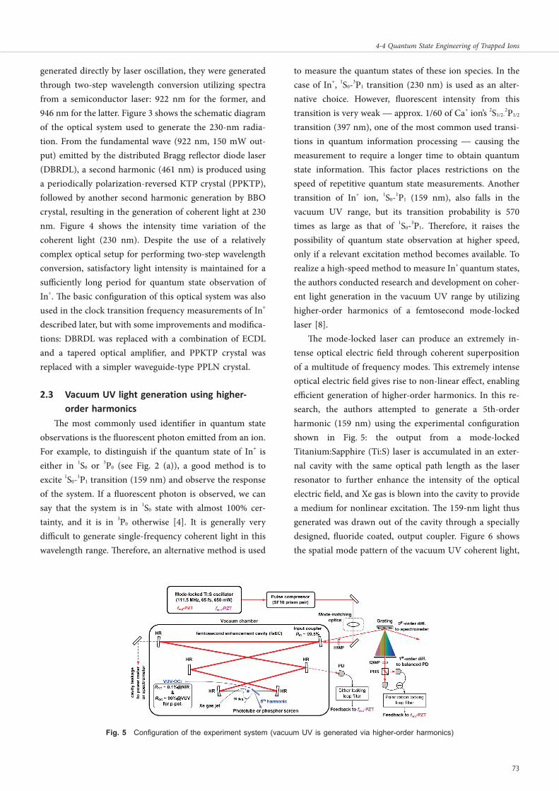
The mode-locked laser can produce an extremely in-tense optical electric field through coherent superposition of a multitude of frequency modes. This extremely intense optical electric field gives rise to non-linear effect, enabling efficient generation of higher-order harmonics. In this re-search, the authors attempted to generate a 5th-order harmonic (159 nm) using the experimental configuration shown in Fig. 5: the output from a mode-locked Titanium:Sapphire (Ti:S) laser is accumulated in an exter-nal cavity with the same optical path length as the laser resonator to further enhance the intensity of the optical electric field, and Xe gas is blown into the cavity to provide a medium for nonlinear excitation. The 159-nm light thus generated was drawn out of the cavity through a specially designed, fluoride coated, output coupler. Figure 6 shows the spatial mode pattern of the vacuum UV coherent light,
Fig.F 5 Configuration of the experiment system (vacuum UV is generated via higher-order harmonics)
Pulse compressor(SF10 prism pair)
Vacuum chamberInput couplerRIC ~ 99.5%
HR
0th-order diff. to spectrometer
1st-order diff. to balanced PD
Xe gas jet
VUV-OC: ROC ~ 0.1%@NIR
& ROC ~ 90%@VUV
for p-pol.
Title:J2017Q-04-04.indd p73 2018/01/19/ 金 15:42:26
73
4-4 Quantum State Engineering of Trapped Ions

which was obtained by irradiating the light on a fluorescent screen placed outside the cavity. Its intensity profile is quite similar to Gaussian distribution, promising feasibility to collimate on a single ion.
Figure 7 shows the intensity profile of 159-nm light as measured outside the cavity. The horizontal axis in the figure represents fundamental leakage from the cavity. The maximum output at 159 nm reached 6.4 μW against 650 mW Ti:S laser input, and the input-output relation indi-cated a good fit to the 5th power curve (i.e. The intensity of output light is proportional to the 5th power of funda-mental wave intensity). This promises availability of stronger output light by enhancing the fundamental wave.
The output light at 159 nm consists of as many fre-quency modes as about 1.9 × 10⁵, but only a few of them are capable of resonating with 1S0-1P1 transition of In+. The authors evaluated the number of 159-nm fluorescent pho-tons that should be observed when the resonant frequency modes were used in quantum state measurement of a single In+. Assuming ideal collimation and measuring conditions, the calculation indicated the following: 87 photons/sec/μW. In view of the currently available output power (6.4 μW), the above calculation predicts 550 photons per second, which roughly corresponds to the typical number (approx. 500/sec) that would be available if the alternative method — use of 1S0-3P1 transition — is em-ployed. Note that there is still space for improvement to perform quantum state measurement of In+ at a higher rate. Some of the possibilities include the pursuit of long-term system stability, and implementation of an optical system for efficient introduction to the ion trap.
3 Sympathetic cooling of indium ion
The ion trap is a device designed for stable accumula-tion of charged particles, but it does not feature the ability to cool them by itself. To control and/or measure quantum
states of ions, they must be brought into a quiescent state by employing a cooling method. The most common method used for this purpose is laser cooling, but with limited applicability because it shows selectivity to specific ion species. In+ is an example of an ion that defies easy laser cooling because of the lack of relevant optical transi-tions. In this research, the authors targeted Ca+ (relatively easy to laser cool) as the media to sympathetically cool In+ for control and measurement.
3.1 Observation of sympathetically cooled indium ion
The motions of multiple of ions accumulated in an ion trap exhibit a collective nature under the influence of the trapping electric field and inter-ion coulomb force, and can be described as a collective vibration mode. Laser cooling an ion translates into cooling of a collective vibration mode in its entirety. This cooling method, called sympathetic cooling, enables cooling of ion species that are not readily cooled independently. The authors conducted experiments to sympathetically cool In+, for which Ca+ and In+ are ac-cumulated in a linear ion trap, and Ca+ was laser cooled.
Figure 8 (a), (b), and (c) show resonance fluorescence images from Ca+ ions captured by a feeble-light imaging device. These images represent the array of three ions: an In+ ion is added to the two laser-cooled Ca+ ions by way of resonance photoionization. These images were obtained by driving the trap under application of very weak voltage that only suffices to interchange positions among the ions, and indicates the existence of a non-fluorescent ion. The frequency at which the ion array vibrates collectively is determined by the arrangement and mass of the constituent ions. Based on this principle, the non-fluorescent ion can be identified to be In+ (mass 115) using the vibration mode frequency measurement method described below.
Fig.F 7 Intensity profile of the 159-nm lightFig.F 6 Fluorescent image of the vacuum UV coherent light
Title:J2017Q-04-04.indd p74 2018/01/19/ 金 15:42:26
4 Quantum Node Technology
74 Journal of the National Institute of Information and Communications Technology Vol. 64 No. 1 (2017)

3.2 Array control of two ion speciesAs described above, it was confirmed that even an ion
species that defies direct laser cooling can be brought into a quiescent state by utilizing sympathetic cooling. The next issue is to control the arrangement of the ions: the target ion must be positionally controlled for its quantum state to be measured. For example, In+ ion should preferably be positioned as in Fig. 8 (a) in view of optical frequency standard applications. For this purpose, the authors devel-oped a method to maintain specific ion arrangements, whereby the dependency of the collective vibration mode frequency on the arrangement and mass of each ion species is utilized [9]. The calculated in-phase frequencies (all ions vibrate in coordinated phase along the array axis) were ν1 (=100.5 kHz) for array (a), and ν2 (=98.5 kHz) for arrays (b) and (c). Figure 9, from (1) to (4), represents time evolution of the array, in which time (vertical axis) is plot-ted against coordinate values of the array axis (fluorescence intensity is color-coded against the background). Spontaneous emission from Ca+ (as shown in (1)) can produce recoil leading to random transpositions among the ions as shown in (a), (b), and (c). This situation can be simulated by controlling the trap potential appropriately.
Applying the frequency characteristic to array (b) and (c) (i.e. ν2) to trap potential excites a mode of collective vibra-tion that makes the arrays (b) and (c) unstable as shown in (2). This unstable situation is resolved at the moment the array is reconfigured to (a). Conversely, applying the frequency of array (a) (i.e. ν1) to modulate the intensity of a 397-nm laser (used for laser cooling of Ca+) makes the array unstable and induces its transition to (b) and (c) to regain stability (see (3)). Figure 9 (4) represents the situa-tion in which array (a) is constantly maintained: at the moment array (b) or (c) arises, ν2 is applied to destabilize the system to induce a return to array (a). This selective destabilization approach enables control and measurement of quantum states with In+ always positioned at the center. The authors consider this approach applicable to systems consisting of a larger number of ions.
3.3 Sideband coolingThe vibrational state of ionic motion, when quantized
in an ion trap, can be specified by the number of phonons (a quantum number) existing in the system. The elec-tronic state of the ions is manipulated by the laser, thus the number of phonons in the system can be controlled by adjusting the laser frequency. By removing the phonons from the system one by one through careful adjustment of the laser frequency, the vibration state can be brought into the ground state. This approach is called sideband cooling. The authors conducted research [10], in collaboration with researchers from Osaka University Graduate School of Engineering Science, whose objective was to implement sideband cooling in a two-ion system (an ionic array consisting of a Ca+ and an In+) whereby electronic transi-tion of Ca+ is exploited. When sideband cooling is applied to the system while it is vibrating in an out-of-phase mode (one of the vibration modes in a two-ion system where the ions vibrate antiphase to each other), the average number of phonons was found to be 0.096 [10]. This value indicates
Fig.F 9 Control of ion array
(2) (3) (4)(1)
200s
Fig.F 8 Sympathetic cooling of an In+ using two Ca+ ions
8
(a)
(b)
(c)
Title:J2017Q-04-04.indd p75 2018/01/19/ 金 15:42:26
75
4-4 Quantum State Engineering of Trapped Ions

that the system was cooled to its vibrational ground state. It also implicates the applicability of quantum logic spec-troscopy to retrieving quantum state information of In+ through manipulation of phonons [11], and the possibility of reducing frequency shift of optical frequency standards (caused by relativistic time dilation) down to 10-17 or below.
4 Measurement of indium ion clock transition frequency
The ionic quantum system described above served for further research and development in the NICT Space-Time Standards Laboratory with an aim to develop state-of-the-art control and measurement technologies to be applied in optical frequency standards. Optical frequency standards involve such techniques as stabilization of laser frequency, and feedback control of the stabilized frequency to the central frequency of atomic/ionic narrow linewidth transi-tion (clock transition) to realize universally available highly accurate optical frequency. The optical frequency is converted to the frequency in the microwave domain to establish an exact second signal, whereby a tool called an optical frequency comb is used to convert frequency with-out compromising accuracy. One of the two main methods to establish optical frequency standards, the single-ion frequency standard, was proposed by H. Dehmelt in the 1980s. Research conducted in line with this method used 27Al+ and 171Yb+ as the frequency references, and reported that it involved uncertainty on the level of 10-18 [4].
In+ was also included among the candidate ions pro-posed by him as the ions species to establish single-ion frequency standards, and recent theoretical research [4] predicted uncertainty on the level of 10-18 due to small frequency shifts it may involve. An additional merit inher-ent to In+ is the fact that it allows the use of relatively simple techniques to measure quantum state. Other candi-dates require complicated technologies. An alternative multi-ion optical frequency standard, which takes advan-tage of these merits and integrates the features of the currently mainstream two approaches, has also been pro-posed [4]. Up to the present, only two research projects have been published on the subject of In+ application to clock frequency measurement, and the uncertainty re-ported by these papers remained on the level of 10-13 [12][13]. It is also noted that the reported frequencies have discrep-ancies larger than about 1 kHz, which lies beyond the range ascribable to experimental errors. The authors conducted clock frequency measurements using In+ as the frequency
reference, the first-stage objective of which was to reduce uncertainty in measurements to help establish the transi-tion frequency.
In past experiments, laser cooling was performed using In+ ion itself, and clock transition frequency was measured in reference to the frequency standard that had been cali-brated in other organizations. In the experiments described in this report, frequency measurements were performed against In+, sympathetically cooled using Ca+, with refer-ence to two in-house (NICT) calibrated frequency stan-dards. Fluorescent light from 1S0-3P1 transition (see Fig.2 (a)) was measured to determine the quantum states of In+: coherent light (clock laser) was first irradiated to excite clock transition, and the response of In+ was observed using a 230-nm coherent light source. If a fluorescent photon is captured in this observation, then the clock transition was not excited, and non-capture of it indicates successful excitation. Based on these data, excitation prob-ability was calculated and the spectrum of clock transition was obtained. In this experiment, the number of photons emitted from In+ was around 250 in one second. Figure 10 shows an example of spectra. Two symmetrically distrib-uted spectra (centered at the clock transition frequency ν0) were obtained by changing the initial state of In+ and by changing the polarization of the clock laser. The fre-quency ν0 was determined by averaging ν+ and ν- (center values of these peaks) of these spectra. While the spectrum was being measured, the clock laser frequency was deter-mined with reference either to NICT-generated Coordinate Universal Time (UTC (NICT)) or to a Sr optical lattice clock. The measurements were taken 36 times and a set of ν0 values was obtained from these experiments. The clock transition frequency was determined as the average of these
Fig.F 10 In+ clock transition spectrum
Title:J2017Q-04-04.indd p76 2018/01/19/ 金 15:42:26
4 Quantum Node Technology
76 Journal of the National Institute of Information and Communications Technology Vol. 64 No. 1 (2017)

values. After evaluating various factors — systematic shift in In+ due to residual magnetic fields and other physical conditions, systematic shift due to frequency link from the frequency standard, and others — the clock frequency was finally determined to be 1 267 402 452 901 049.9 (6.9) Hz. The frequency values obtained in this study and those re-ported in the past research are compared in Fig.11 (“Garching, 2000” indicates the values from reference [12], and “Erlangen, 2007” from reference [13]). As described above, the measurements reported here successfully deter-mined In+ clock transition frequency with the least uncer-tainty ever (5.4 ×10⁻¹⁵) [14]. Zeeman shift due to residual magnetic fields is the most dominant factor affecting the magnitude of uncertainty. Therefore, further improvements in terms of polarization in magnetic sublevels and imple-mentation of an effective magnetic shield are expected to reduce uncertainty, leading to realize more reliable optical frequency standards.
5 Summary
In this report, we described research and development of state-of-the-art control and measurement methods tar-geted at ionic quantum systems. This work was conducted as a part of our efforts to explore quantum node applica-tions. As a step to achieve our goal, we constructed a coher-ent optical source system that enables manipulating and observing an ionic quantum system, and established a technique to sympathetically cool In+ using Ca+. The sympathetically-cooled In+ ion was applied to clock transi-tion frequency measurements leading to the first successful measurements on the 10-15 level. Additional application of sideband cooling, with some improvement in the current method, places expectations on reducing frequency shift
due to time dilation down to the level of 10-17. Realization of quantum state measurement of In+ by means of vacuum ultraviolet light promises another expectation: substantial upgrade of the stability of optical frequency standards under operating conditions.
The optical frequency standards based on ions are cur-rently operated solely in single-ion mode. However, a combination of a type of ion trap technique — suited for sympathetic cooling and multi-ion operation — and a quantum state measurement method such as presented in this report is expected to lead the way to a new scheme called “multi-ion optical frequency standard [15]” that will provide significant progress in stability. In addition, trans-fer of the quantum state associated with the clock transition of sideband-cooled In+ to Ca+ through the action of linear ion trapped phonons enables the creation of the state of quantum entanglement with the In+ ticking standard time-base within a separate ion trap. Actualization of such quantum state operations promises the future implementa-tion of ultimate quantum networks among atomic clocks [16].
Acknowledgments
The authors express deep gratitude and appreciation to Dr. Hidekazu HACHISU who operated the Sr optical lattice clock and granted us to use its data, and those who helped us in many ways through the course of this study including Mr. Hiroshi ISHIJIMA, Mr. Michiaki MIZUNO, Dr. Yuko HANADO, Dr. Masahiro TAKEOKA, and Dr. Masahide SASAKI.
ReReRenReR 1 D. Leibfried, R. Blatt, C. Monroe, and D. Wineland, “Quantum dynamics of
single trapped ions,” Review of Modern Physics, 75, 281 (2003). 2 M. Keller, B. Lange, K. Hayasaka, W. Lange, and H. Walther, “Continuous
generation of single photons with controlled waveform in an ion-trap cavity system,” Nature 431, 1075(2004).
3 R. Blatt and C. F. Roos, “Quantum simulations with trapped ions,” Nature Physics 8, 277–284 (2012).
4 A. D. Ludlow, M. M. Boyd, J. Ye, E. Peik, and P. O. Schmidt, “Optical atomic clocks,” Review of Modern Physics 87, 637 (2015).
5 J. Labaziewicz, P. Richerme, K. Brown, I. L. Chuang, and K. Hayasaka, “Compact, filtered diode laser system for precision spectroscopy,” Optics Letters 32, 572 (2007).
6 Kazuhiro Hayasaka, “Modulation-free optical locking of an external-cavity di-ode laser to a filter cavity,” Optics Letters 36, 2188 (2011).
7 Y. Kawai, U. Tanaka, K. Hayasaka, and S. Urabe, “Mode-hop-free operation of a distributed Bragg reflector diode laser in an external fiber-cavity configura-tion,” Applied Physics B 121, 213 (2015).
8 K. Wakui, K. Hayasaka, and T. Ido, “Generation of vacuum ultraviolet radiation
Fig.F 11 Comparison of In+ clock transition frequency: past and current experiments
Garching, 20001 267 402 452 899 920 (230)
Erlangen 20071 267 402 452 901 265 (256)
Tokyo, 20171 267 402 452 901 049.9 (6.9)
899600 900000 900400 900800 901200 901600Absolute frequency ‒ 1 267 402 452 000 000 [Hz]
Title:J2017Q-04-04.indd p77 2018/01/19/ 金 15:42:26
77
4-4 Quantum State Engineering of Trapped Ions

by intracavity high-harmonic generation toward state detection of single trapped ions,” Applied Physics B 117, 957(2014).
9 K. Hayasaka, “Synthesis of two-species ion chains for a new optical frequency standard with an indium ion,” Applied Physics B 107, 965(2012).
10 U. Tanaka, T. Kitanaka, K. Hayasaka, and S. Urabe, “Sideband cooling of a Ca+–In+ ion chain toward the quantum logic spectroscopy of In+,” Applied Physics B 121, 147 (2015).
11 Kazuhiro Hayasaka, ”Quantum computer and optical frequency standards,” Journal of Japanese Physical Society 69, 830(2014) (in Japanese).
12 J. von Zanthier, Th. Becker, M. Eichenseer, A. Yu. Nevsky, Ch. Schwedes, E. Peik, H. Walther, R. Holzwarth, J. Reichert, Th. Udem, T.W. Hänsch, P.V. Pokasov, M.N. Skvortsov, and S.N. Bagayev, “Absolute frequency measure-ment of the In+ clock transition with a mode-locked laser,” Optics. Letters 25, 1729 (2000).
13 Y. H. Wang, R. Dumke, T. Liu, A. Stejskal, Y. N. Zhao, J. Zhang, Z. H. Lu, L. J. Wang, Th. Becker, and H. Walther, “Absolute frequency measurement of the 115In+ 5s2 1S0-5s5p 3P0 narrowline transition,” Optics Communications 273, 526 (2007).
14 N. Ohtsubo, Y. Li, K. Matsubara, T. Ido, and K. Hayasaka, “Frequency measure-ment of the clock transition of an indium ion sympathetically-cooled in a linear trap,” Optics Express, 25, 11725 (2017).
15 K. Pyka, N. Herschbach , J. Keller , and Tanja E. Mehlstäubler, “A high-precision segmented Paul trap with minimized micromotion for an optical multiple-ion clock,” Applied Physics B 114, 231 (2014).
16 P. Kómár, E. M. Kessler, M. Bishof, L. Jiang, A. S. Sørensen, J. Ye and M. D. Lukin, “A quantum network of clocks,” Nature Physics 10, 582 (2014).
Kazuhiro HAYASAKA, Ph.DResearch Manager, Quantum ICT Advanced Development CenterQuantum electronics, Quantum optics, Optical clock
Kentaro WAKUI, Ph.DPlanning Manager, Strategic Planning Office, Strategic Planning DepartmentQuantum optics, Quantum electronics
Nozomi OHTSUBO, Ph.DResearcher, Space-Time Standards laboratory, Applied Electromagnetic reserch InstituteOptical frequency standards, Quantum electronics
Ying LI, Ph.DTemporary Staff, Space-Time Standards laboratory, Applied Electromagnetic reserch InstituteOptical frequency standards, Laser physics
Kensuke MATSUBARA, Ph.DSenior Researcher, Space-Time Standards laboratory, Applied Electromagnetic reserch InstituteQuantum electronics, Time and frequency standards
Tetsuya IDO, Ph.DDirector, Space-Time Standards laboratory, Applied Electromagnetic reserch InstituteOptical frequency standards, Optical precision measurements, Laser cooling
Title:J2017Q-04-04.indd p78 2018/01/19/ 金 15:42:26
4 Quantum Node Technology
78 Journal of the National Institute of Information and Communications Technology Vol. 64 No. 1 (2017)